KR20140009327A - Laminar structure providing adaptive thermal insulation - Google Patents
Laminar structure providing adaptive thermal insulation Download PDFInfo
- Publication number
- KR20140009327A KR20140009327A KR1020137022820A KR20137022820A KR20140009327A KR 20140009327 A KR20140009327 A KR 20140009327A KR 1020137022820 A KR1020137022820 A KR 1020137022820A KR 20137022820 A KR20137022820 A KR 20137022820A KR 20140009327 A KR20140009327 A KR 20140009327A
- Authority
- KR
- South Korea
- Prior art keywords
- envelope
- layer
- gas generating
- generating agent
- cavity
- Prior art date
Links
Images


Classifications
-
- A—HUMAN NECESSITIES
- A41—WEARING APPAREL
- A41D—OUTERWEAR; PROTECTIVE GARMENTS; ACCESSORIES
- A41D31/00—Materials specially adapted for outerwear
- A41D31/04—Materials specially adapted for outerwear characterised by special function or use
- A41D31/08—Heat resistant; Fire retardant
- A41D31/085—Heat resistant; Fire retardant using layered materials
-
- A—HUMAN NECESSITIES
- A41—WEARING APPAREL
- A41D—OUTERWEAR; PROTECTIVE GARMENTS; ACCESSORIES
- A41D31/00—Materials specially adapted for outerwear
- A41D31/02—Layered materials
-
- A—HUMAN NECESSITIES
- A62—LIFE-SAVING; FIRE-FIGHTING
- A62B—DEVICES, APPARATUS OR METHODS FOR LIFE-SAVING
- A62B17/00—Protective clothing affording protection against heat or harmful chemical agents or for use at high altitudes
- A62B17/003—Fire-resistant or fire-fighters' clothes
-
- B—PERFORMING OPERATIONS; TRANSPORTING
- B32—LAYERED PRODUCTS
- B32B—LAYERED PRODUCTS, i.e. PRODUCTS BUILT-UP OF STRATA OF FLAT OR NON-FLAT, e.g. CELLULAR OR HONEYCOMB, FORM
- B32B5/00—Layered products characterised by the non- homogeneity or physical structure, i.e. comprising a fibrous, filamentary, particulate or foam layer; Layered products characterised by having a layer differing constitutionally or physically in different parts
- B32B5/22—Layered products characterised by the non- homogeneity or physical structure, i.e. comprising a fibrous, filamentary, particulate or foam layer; Layered products characterised by having a layer differing constitutionally or physically in different parts characterised by the presence of two or more layers which are next to each other and are fibrous, filamentary, formed of particles or foamed
- B32B5/24—Layered products characterised by the non- homogeneity or physical structure, i.e. comprising a fibrous, filamentary, particulate or foam layer; Layered products characterised by having a layer differing constitutionally or physically in different parts characterised by the presence of two or more layers which are next to each other and are fibrous, filamentary, formed of particles or foamed one layer being a fibrous or filamentary layer
- B32B5/26—Layered products characterised by the non- homogeneity or physical structure, i.e. comprising a fibrous, filamentary, particulate or foam layer; Layered products characterised by having a layer differing constitutionally or physically in different parts characterised by the presence of two or more layers which are next to each other and are fibrous, filamentary, formed of particles or foamed one layer being a fibrous or filamentary layer another layer next to it also being fibrous or filamentary
-
- Y—GENERAL TAGGING OF NEW TECHNOLOGICAL DEVELOPMENTS; GENERAL TAGGING OF CROSS-SECTIONAL TECHNOLOGIES SPANNING OVER SEVERAL SECTIONS OF THE IPC; TECHNICAL SUBJECTS COVERED BY FORMER USPC CROSS-REFERENCE ART COLLECTIONS [XRACs] AND DIGESTS
- Y10—TECHNICAL SUBJECTS COVERED BY FORMER USPC
- Y10T—TECHNICAL SUBJECTS COVERED BY FORMER US CLASSIFICATION
- Y10T428/00—Stock material or miscellaneous articles
- Y10T428/24—Structurally defined web or sheet [e.g., overall dimension, etc.]
- Y10T428/24025—Superposed movable attached layers or components
Abstract
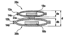
본 발명은 적응적 단열을 제공하는 라미나 구조체(10)에 관한 것으로, 라미나 구조체는, 제1 층(12)과, 제2 층(14)과, 상기 제1 층(12)과 상기 제2 층(14) 사이에 제공되는 적어도 하나의 공동(16)과, 비활성화 형태와 활성화 형태를 갖고, 상기 공동(16) 내의 온도의 증가에 응답하여 상기 공동(16) 내부의 가스 압력을 증가시키도록 상기 비활성화 형태로부터 상기 활성화 형태로 변화하도록 된 가스 발생 작용제(18)를 포함하고, 상기 제1 층(12), 상기 제2 층(14) 및 상기 공동(16)은 상기 제1 층(12)과 상기 제2 층(14) 사이의 거리가 상기 공동(16) 내의 가스 압력의 증가에 응답하여 증가하도록 배치된다. The present invention relates to a lamina structure (10) that provides adaptive thermal insulation, wherein the lamina structure includes a first layer (12), a second layer (14), the first layer (12) and the first agent. At least one cavity 16 provided between the two layers 14 and having an inactive form and an activated form, in which the gas pressure inside the cavity 16 is increased in response to an increase in temperature in the cavity 16. And a gas generating agent 18 adapted to change from the deactivated form to the activated form, wherein the first layer 12, the second layer 14, and the cavity 16 comprise the first layer 12. ) And the second layer 14 are arranged to increase in response to an increase in gas pressure in the cavity 16.
Description
본 발명은 적응적 단열을 제공하는 구조체에 관한 것으로, 보다 상세하게는 적응적 단열을 제공하는 라미나(laminar) 구조체에 관한 것이다. 이러한 라미나 구조체는 섬유 또는 직물의 설계, 특히 방호복 또는 장갑 등의 다른 기능성 의복과 같은 의복 등의 개인 보호 장비를 위한 용례에 사용될 수 있다.FIELD OF THE INVENTION The present invention relates to structures that provide adaptive thermal insulation, and more particularly to lamina structures that provide adaptive thermal insulation. Such lamina structures can be used in the design of fibers or fabrics, in particular for personal protective equipment such as garments such as protective clothing or other functional garments such as gloves.
방호복 또는 기능성 의복은 통상 환경적 영향에 대해 착용자의 보호가 필요하거나 주어진 환경적 조건하에서 원하는 기능적 특성을 제공하는 것이 필요한 소방, 법률 집행, 군사 또는 산업적 작업 등의 용례에 사용된다. 의복은 착용자를 열, 화염, 또는 액체에 의한 충격으로부터 보호하는 데에 필요할 수 있다. 통상, 의복은 착용자가 자신이 해야할 일을 수행할 수 있을 정도로 착용자에게 충분한 편안함을 제공하는 것이 바람직하다.Protective or functional garments are typically used in applications such as fire fighting, law enforcement, military or industrial work that require the protection of the wearer against environmental influences or that provide the desired functional properties under given environmental conditions. Clothing may be necessary to protect the wearer from heat, flames, or liquid shocks. Typically, it is desirable for the garment to provide the wearer with sufficient comfort so that the wearer can perform the task at hand.
방호복 또는 기능성 의복이 사용되는 하나의 용례로서 소방복에 대해 말하자면, 이러한 의복은 한편으로 화염과 열에 대해 상당한 정도의 단열을 제공하는 것이 필요하다. 이것은 의복이 외부로부터 내부까지 의복을 통한 열전달을 효율적으로 억제하는 것을 필요로 한다. 통상, 소방복은 소방수가 의복을 입고 있으면서 자신의 일을 효율적으로 수행할 수 있도록 충분한 유연성과 통기성을 제공하는 것이 필요하다. 이것은 의복이 자체를 통해 내부로부터 외부로 어느 정도 수증기 전달을 허용하는 것(통기성)이 필요하다.Speaking of fire fighting clothing as one application in which protective or functional clothing is used, it is necessary, on the one hand, to provide a considerable degree of insulation against flame and heat. This necessitates that the garment efficiently suppress heat transfer through the garment from the outside to the inside. Typically, firefighting suits need to provide sufficient flexibility and breathability for firefighters to perform their work efficiently while wearing clothing. This necessitates that the garment allows for some degree of water vapor transfer from inside to outside through itself (breathable).
소방복에 의해 제공될 단열은 광범위한 환경적 온도 하에서 효과적인 것이 필요하다: 극한의 경우를 말하자면, 소방복은 환경적 온도가 약 1000℃ 이상일 수 있는 화재에서 화염의 "플래시오버(flashover)"에 노출시 소방수를 보호하기에 충분한 단열을 제공하는 것이 필요하다. 이러한 경우, 의복은 적어도 일시적으로는 의복의 외피에서 약 800-900℃의 온도에 노출될 것이다. 심한 화재라면, 소방수가 화염에 가까이 접근하여야 할 때 의복의 외피는 여전히 약 350℃까지의 온도에 있을 것으로 예상된다. 소방수의 피부의 온도는 약 24℃ 이하로 증가되게 하는 것이 바람직하다.The insulation to be provided by fire suits needs to be effective under a wide range of environmental temperatures: In extreme cases, fire suits may require firefighters to be exposed to "flashover" of flames in fires where environmental temperatures may be around 1000 ° C or higher. It is necessary to provide sufficient insulation to protect it. In such cases, the garment will be exposed, at least temporarily, to a temperature of about 800-900 ° C. in the outer shell of the garment. In severe fires, the outer shell of the garment is still expected to be at temperatures up to about 350 ° C when firefighters need to approach the flame. It is desirable to allow the temperature of the firefighter's skin to increase below about 24 ° C.
화재와 무관한 기술적 작업에서, 전통적인 소방복은 통상은 필요하지 않은 열적 성능 수준을 제공하고 두껍고 무거운 의복층에 기인하여 낮은 편의도(예, 의복의 낮은 통기성)가 얻어진다. 의복이 광범위한 단열을 제공하는 것이 필요한 전술한 소방복과 같은 용례에서, 정적인 구조에 의해, 즉, 언제나 최악의 시나리오에 필요한 단열을 제공하는 구조에 의해 모든 요건을 만족시키는 것은 통상 곤란하다.In fire-independent technical operations, traditional firefighting garments typically provide undesired levels of thermal performance and low comfort (eg, low breathability of the garment) is achieved due to thick and heavy layers of clothing. In applications such as the firefighting suit described above where garments need to provide extensive insulation, it is usually difficult to meet all requirements by static structure, ie by structure that always provides the necessary insulation for worst case scenarios.
다수의 동적인 개념들이 제안되었다. 이러한 동적인 개념의 배경 사상은 주어진 환경적 조건에 따라 단열 정도를 달리 제공하는 구조를 형성하는 것이다. 제공되는 단열은 구조의 외측 및/또는 내측에서 겪는 환경적 온도에 적응할 수 있다.Many dynamic concepts have been proposed. The idea behind this dynamic concept is to form a structure that provides different degrees of insulation depending on the given environmental conditions. The insulation provided can adapt to the environmental temperatures experienced outside and / or inside the structure.
소방 분야에서, 팽창 시스템의 개념이 개발되어서, 예컨대 방화 도어용 팽창 가스켓 또는 배관용 팽창 코팅의 형태 등의 다양한 용례에 사용되고 있다. 이러한 팽창 시스템은 통상적으로 열에 노출되는 상태에서 발포 처리되어 부피가 증가함으로써 단열성을 증가시키는 고체를 갖는 팽창성 물질을 포함한다. 통상 이러한 발포 과정은 팽창성 물질이 이미 정해진 활성화 온도에 도달하면 시작한다. 발포 과정의 결과, 팽창성 물질은 다공질이 됨으로써, 즉 밀도가 감소하고 부피가 증가하지만 여전히 고체 구조를 갖는 것을 유지한다. 통상적인 팽창성 물질은 규산 나트륨, 팽창성 그래파이트 또는 탄소 및 상당량의 수화물을 포함하는 물질이다.In the field of firefighting, the concept of expansion systems has been developed and used in various applications, such as in the form of expansion gaskets for fire doors or expansion coatings for piping. Such inflation systems typically include intumescent materials having a solid that is foamed under heat exposure to increase its volume by increasing its volume. Typically, this foaming process begins when the expandable material has already reached a predetermined activation temperature. As a result of the foaming process, the expandable material becomes porous, that is, decreases in density and increases in volume but still retains a solid structure. Typical expandable materials are those that include sodium silicate, expandable graphite or carbon and significant amounts of hydrates.
소방복 또는 다른 기능성 의복을 제조하기 위해 팽창성 물질을 사용하는 것이 제안된 바 있다. US 2009/0111345 A1은 통기성을 유지하면서 착용자를 열이나 화염으로부터 보호하기 위해 방수성의 수증기 투과 직물/의복에 대해 적응적 단열을 제공하는 구조를 개시한다. 고분자 수지-팽창성 그래파이트 혼합물을 기초로 한 팽창성 물질은 화염 장벽층과 방수 장벽층 사이에 위치된다. US 2009/0111345 A1은 약 200℃의 활성화 온도와, 300℃에 90초간 노출 후 적어도 200%의 팽창성 물질의 부피 증가를 특정한다. 시험은 소방복의 직물에 적용시 이러한 접근이 한계가 있음을 보여주었다.It has been proposed to use intumescent materials to make fire fighting or other functional garments. US 2009/0111345 A1 discloses a structure that provides adaptive insulation to waterproof vapor permeable fabrics / garments to protect the wearer from heat or flame while maintaining breathability. An expandable material based on the polymer resin-expandable graphite mixture is located between the flame barrier layer and the waterproof barrier layer. US 2009/0111345 A1 specifies an activation temperature of about 200 ° C. and a volume increase of the expandable material of at least 200% after 90 seconds of exposure to 300 ° C. Tests have shown that this approach is limited when applied to fabrics of fire fighting clothing.
팽창성 메커니즘을 통해 열적 보호를 제공하는 난연성 플렉시블 물질을 제조하기 위한 추가의 방안이 WO 2009/025892 A2에 제시된다. 이러한 물질에는 복수의 개별 가드 플레이트가 플렉시블 기재 직물의 외부면에 서로에 대해 이격된 관계로 부착된다. 가드 플레이트는 충분한 열에 노출시 크게 팽창하는 팽창성 물질을 포함한다. 따라서, 활성화시 연속적 단열 및 난연성 외부 쉘 필름이 형성된다. 일 실시예에서, 가드 플레이트는 열에 노출시 증발되는 물 또는 수용액을 포함하는 열팽창성 마이크로캡슐을 포함함으로써, 화염원으로부터의 열을 흡수하고, 마이크로캡슐을, 해당 마이크로캡슐이 파열되어 그 내용물을 유리시켜 산소를 몰아내고 화염을 급냉시킬 때까지 팽창시킨다. 함수 마이크로갭슐의 활성화 온도는 약 100-400℃인 것으로 보고되고 있다.Further methods for producing flame retardant flexible materials that provide thermal protection through an expandable mechanism are presented in WO 2009/025892 A2. In such materials a plurality of individual guard plates are attached to the outer surface of the flexible base fabric in spaced relation to one another. The guard plate contains an intumescent material that expands significantly upon exposure to sufficient heat. Thus, upon activation, a continuous thermal and flame retardant outer shell film is formed. In one embodiment, the guard plate comprises thermally expandable microcapsules comprising water or an aqueous solution that evaporates upon exposure to heat, thereby absorbing heat from the flame source and discharging the microcapsules, causing the microcapsules to rupture and release their contents. To expel oxygen and expand until the flame is quenched. The activation temperature of the hydrous microcapsules is reported to be about 100-400 ° C.
팽창성 시스템의 대안으로서, 형상 기억 합금 또는 바이메탈 재료를 사용하여 소방복에 대해 적응적 단열을 제공하는 것이 제안된 바 있는데, WO 99/05926 A1을 참조할 수 있다. 이러한 방안에 따르면, 동적인 적응적 단열 시스템은 외부 쉘 직물과 내부 라이너 직물 사이에 배치된 스페이서 물질을 기초로 한다. 스페이서 물질은 나선 형상, 트루프(trough) 형상, 또는 코일 형상으로 전개되는 형상 기억 합금일 수 있거나, 바이메탈 스트립 또는 스냅 디스크일 수 있다. 약 65-75℃(형상 기억 합금)와 50℃(바이메탈 스트립)의 활성화 온도가 보고되고 있다. 전술한 팽창성 시스템을 기초로 한 제안과 달리, WO 99/05926 A1은 기본적으로 복수 개의 활성화/정지 사이클을 수행할 수 있는 가역적 시스템을 제공한다.As an alternative to the expandable system, it has been proposed to provide adaptive insulation for fire fighting suits using shape memory alloys or bimetallic materials, see WO 99/05926 A1. According to this approach, the dynamic adaptive insulation system is based on a spacer material disposed between the outer shell fabric and the inner liner fabric. The spacer material may be a shape memory alloy that develops in a spiral shape, trough shape, or coil shape, or may be a bimetallic strip or a snap disk. Activation temperatures of about 65-75 ° C. (shape memory alloys) and 50 ° C. (bimetallic strips) are reported. In contrast to the proposal based on the expandable system described above, WO 99/05926 A1 basically provides a reversible system capable of performing a plurality of activation / stop cycles.
WO 2008/097637 A1은 외부 쉘 직물, 수분 장벽층 및 열적 라이너를 포함하는 열적 장벽을 갖는 복합 직물 시스템을 개시한다. 열적 라이너는 비활성화 상태에서 열가소성 결합제에 의해 압축 상태로 유지되는 권축(crimped) 내열 섬유로 된 적어도 하나의 열팽창성 불연 직물을 포함한다. 열적 라이너가 열이나 화염에 노출되면, 라이너는 적어도 3배 정도 두께가 증가하는 것으로 보고된다.WO 2008/097637 A1 discloses a composite fabric system having a thermal barrier comprising an outer shell fabric, a moisture barrier layer and a thermal liner. The thermal liner includes at least one thermally expandable non-combustible fabric of crimped heat resistant fibers that are kept compressed by the thermoplastic binder in an inactive state. When a thermal liner is exposed to heat or flame, the liner is reported to increase at least three times its thickness.
본 발명의 목적은 고온에 대해 적응적 단열을 허용하는 개선된 라미나 구조체를 제공하는 것이다. 특정 용례에서, 본 발명은 보호 및/또는 기능적 의복, 특히 소방복에 사용되고 상기 개선된 라미나 구조체를 갖는 직물을 제공하는 것이다.It is an object of the present invention to provide an improved lamina structure that allows for adaptive insulation against high temperatures. In certain applications, the present invention is to provide a fabric having protective and / or functional garments, in particular fire fighting suits, and having the improved lamina structure.
본 발명은 적응적 단열을 제공하는 라미나 구조체를 제공하며, 해당 구조체는 제1 층과; 제2 층과; 상기 제1 층과 상기 제2 층 사이에 제공되는 적어도 하나의 공동과; 비활성화 형태와 활성화 형태를 가지고, 상기 공동 내의 온도의 증가에 응답하여 상기 공동 내부의 가스 압력을 증가시키도록 상기 비활성화 형태로부터 상기 활성화 형태로 변하도록 된 가스 발생 작용제를 포함하고; 상기 제1 층, 상기 제2 층 및 상기 공동은 상기 제1 층과 상기 제2 층 사이의 거리가 상기 공동 내의 가스 압력의 증가에 응답하여 증가하도록 배치된다.The present invention provides a lamina structure that provides adaptive thermal insulation, the structure comprising a first layer; A second layer; At least one cavity provided between the first layer and the second layer; A gas generating agent having an inactivated form and an activated form, and adapted to change from the inactivated form to the activated form to increase gas pressure inside the cavity in response to an increase in temperature in the cavity; The first layer, the second layer and the cavity are arranged such that the distance between the first layer and the second layer increases in response to an increase in gas pressure in the cavity.
본 발명은 온도 증가에 응답하여 단열 성능을 향상시키는 적응적 단열 구조체를 제공한다. 최근 이러한 구조체는 온도가 정상적 또는 동작 온도의 범위로부터 상승된 온도의 범위까지 증가할 때 단열 성능의 확실한 증가를 보여줄 수 있음이 증명되었다. 소정의 실시예에서, 저온에서의 제1의(통상은 낮은) 단열 성능으로부터 고온에서의 제2의(통상은 높은) 단열 성능까지의 분명한 향상이 얻어질 수 있다. 바람직한 실시예에서, 단열 성능의 분명한 향상은 활성화 온도와 관련될 수 있는데, 즉 구조체는 온도가 활성화 온도 또는 그 이상으로 증가시에 활성화된다.The present invention provides an adaptive thermal insulation structure that improves thermal insulation performance in response to an increase in temperature. It has recently been demonstrated that such structures can show a clear increase in thermal insulation performance as the temperature increases from a range of normal or operating temperatures to a range of elevated temperatures. In certain embodiments, a clear improvement from the first (usually low) thermal insulation performance at low temperatures to the second (usually high) thermal insulation performance at high temperatures can be obtained. In a preferred embodiment, a clear improvement in adiabatic performance can be related to the activation temperature, ie the structure is activated when the temperature increases above or above the activation temperature.
본 명세서에 사용되는 라미나 구조체는 적어도 해당 구조체가 비활성화 상태에서 길이 및 폭 방향에 의해 정의되는 바와 같이 기본적으로 측방향으로 연장되고 박형인 평면형 또는 시트형 구성을 갖는 구조를 형성한다. 길이와 폭보다 훨씬 작은 길이 및 폭 방향에 직교하는 방향의 두께를 가지면 박형인 구성으로 간주된다. 통상적인 용례에서, 여기에 정의되는 라미나 구조체는 굽힘과 관련하여 가요성의 라미나 구조체이거나 경질의 라미나 구조체가 될 것이다.As used herein, a lamina structure forms a structure having a planar or sheet-like configuration that is essentially laterally extending and thin, as defined by the length and width directions in at least the structure. It is considered to be a thin configuration if it has a thickness in the direction orthogonal to the length and width direction much smaller than the length and width. In typical applications, the lamina structure defined herein will be a flexible lamina structure or a rigid lamina structure with respect to bending.
제1 및 제2 층은 라미나 구조체의 두께 방향으로 서로 마주하도록 배치된 층일 수 있다. 제1 및 제2 층은 반드시 인접한 층일 필요는 없다. 공동 이외에, 절연 재료와 같은 라미나 구조체의 다른 구조적 요소가 제1 및 제2 층 사이에 개재될 수 있다. 제1 및 제2 층은 통상은 기본적으로 서로 평행하고 두께 방향에 직교하도록 연장될 것이다. 제1 및 제2 층 사이의 거리는 두께 방향으로 측정될 수 있다. 제1 및/또는 제2 층이 동일 평면 내에 있지 않지만 돌출부 및/또는 오목부를 갖는 구조를 가지는 경우, 상기 층들 사이의 거리는 주어진 기준 평면을 지칭하도록 의도된다. 실제 구현예에서, 제1 및 제2 층은 예컨대, 제1 층과 제2 층 사이에 공동이 형성되어 있는 제1 직물층 및 제2 직물층과 같은 직물의 층일 수 있다. 제1 층과 제2 층은 각각 내부층 및 외부층으로 지칭될 수 있다. 본 발명의 라미나 구조체를 의복에 사용되는 섬유에 적용하는 측면에서, "내부층"이란 용어는 착용자의 신체를 향하고 통상 착용자의 피부에 가능한 한 밀착되도록 배치되는 층을 의미하고, "외부층"이란 용어는 착용자의 신체로부터 외부 환경으로 멀어지게 향하는 층을 의미한다.The first and second layers may be layers disposed to face each other in the thickness direction of the lamina structure. The first and second layers do not necessarily need to be adjacent layers. In addition to the cavity, other structural elements of the lamina structure, such as insulating material, may be interposed between the first and second layers. The first and second layers will usually extend essentially parallel to each other and perpendicular to the thickness direction. The distance between the first and second layers can be measured in the thickness direction. If the first and / or second layer are not in the same plane but have a structure with protrusions and / or recesses, the distance between the layers is intended to refer to a given reference plane. In a practical embodiment, the first and second layers may be layers of fabric, such as, for example, a first fabric layer and a second fabric layer in which cavities are formed between the first and second layers. The first layer and the second layer may be referred to as an inner layer and an outer layer, respectively. In terms of applying the lamina structure of the present invention to the fibers used in the garment, the term "inner layer" means a layer that is disposed towards the wearer's body and as close to the wearer's skin as possible, and as "outer layer". The term means a layer facing away from the wearer's body into the external environment.
온도 증가에 처할 때, 가스 발생 작용제는 공동 내에서 가스의 생성을 시작할 것이므로 공동 내의 가스 압력이 증가하게 된다. 공동 내부의 가스 압력의 증가는 공동의 "팽창"을 야기한다. 팽창의 결과, 공동은 두께가 증가하므로 제1 및 제2 층 사이의 거리가 증가한다. 그 결과 "가스층" 또는 "공기층"(공기는 제1 층과 제2 층 사이의 공간 내로 진입함)이 제1 층과 제2 층 사이에 형성되어 충분한 단열을 제공하는데, 이는 가스/공기의 낮은 열 전도 및 제1 층과 제2 층 사이의 거리 증가 때문이다.When subjected to an increase in temperature, the gas generating agent will start producing gas in the cavity, thus increasing the gas pressure in the cavity. Increasing the gas pressure inside the cavity causes “cavity” of the cavity. As a result of the expansion, the cavity increases in thickness and therefore the distance between the first and second layers increases. As a result, a "gas layer" or "air layer" (air enters into the space between the first and second layers) is formed between the first and second layers to provide sufficient thermal insulation, which is low Due to heat conduction and increased distance between the first layer and the second layer.
가스 발생 작용제는 제1 및 제2 층 사이의 거리를 증가시키고 단열 부피를 증가시키기 위해 제1 및 제2 층을 서로 멀리 떨어뜨리는 동작을 위한 "동인"이다. 온도에 따라, 가스 발생 작용제는 비활성화 형태와 활성화 형태를 가질 수 있다. 가스 발생 작용제가 비활성화 형태에서, 적응적 단열 구조체는 자체가 비활성화 상태에 있다. 적응적 단열 라미나 구조체의 활성화 상태는 가스 발생 작용제의 형태의 변화에 의해 얻어진다. 비활성화 형태의 가스 발생 작용제는 공동 내에 포함될 수 있다. 가스 발생 작용제는 액체, 고체, 겔 또는 이들의 조합 중 임의의 것일 수 있다. 가스 발생은 물리적 변환(즉, 액체-가스 상 변이 및/또는 고체-가스 상 변이 및/또는 흡착 가스의 방출)을 통해, 화학적 변환(즉, 적어도 일종의 가스 생성물을 방출하는 화학 반응)을 통해, 또는 이들의 조합에 의해 일어날 수 있다. 가스 발생 작용제의 바람직한 활성화 한계치, 예컨대 활성화 온도는 가스 발생 작용제를 적어도 2 성분의 혼합물의 형태로 제공함으로써 적절히 잘 조정될 수 있다. 일례로서, 원하는 비등 온도를 갖는 액체 가스 발생 작용제가 2개 이상의 "순수" 액체를 혼합함으로써 제공될 수 있다. The gas generating agent is a “driver” for the operation of moving the first and second layers away from each other to increase the distance between the first and second layers and to increase the adiabatic volume. Depending on the temperature, the gas generating agent may have an inactivated form and an activated form. In the form of deactivation of the gas generating agent, the adaptive thermal insulation structure is in itself deactivated. The activation state of the adaptive thermally insulating lamina structure is obtained by changing the shape of the gas generating agent. Inert forms of gas generating agents may be included in the cavities. The gas generating agent may be any of a liquid, a solid, a gel or a combination thereof. Gas generation can be achieved through physical transformation (ie, liquid-gas phase transition and / or solid-gas phase transition and / or release of adsorbed gas), through chemical transformation (ie, a chemical reaction that releases at least some kind of gaseous product), Or a combination thereof. Preferred activation limits of the gas generating agent, such as the activation temperature, can be adjusted as appropriate by providing the gas generating agent in the form of a mixture of at least two components. As an example, a liquid gas generating agent having a desired boiling temperature may be provided by mixing two or more "pure" liquids.
본 발명에 따르면, 공동과 가스 발생 작용제는 열적으로 활성화된 팽창 가능한 복합 구조체, 즉 온도 증가시 부피가 증가되는 구조체를 형성한다. 따라서, 본 발명은 온도 증가에 처할 때 팽창성 물질의 거동과 닮은 효과를 제공하지만, 팽창과는 완전히 다른 공정을 이용한다. 여기서 설명되는 라미나 구조체에서 공동과 가스 발생 작용제는 공동의 부피 증가가 제1 및 제2 층 간의 거리를 현저하게 증가시키도록 구성된다. 따라서, 기본적으로 공기 및/또는 가스로 충전된 단열 부피가 제1 및 제2 층 사이에 형성된다. 온도 증가에 따라 조밀한 고체 구조로부터 다공질 고체 구조로 형태가 변하는 공지된 팽창성 물질과 달리, 본 발명에 따른 "준-팽창성" 복합체 구조는 저온에서의 팽창되지 않은 상태로부터 고온에서의 팽창된 상태로 형태가 변한다. 발포 과정이 활성화 이후에 시작되고, 그 결과 상당수의 개별 공동들이 형성되는 공지된 팽창성 물질과 달리, 본 발명은 이미 활성화되지 않은 상태로 존재하는 미리 정해진 형상의 공동을 제공한다. 활성화 이후, 해당 공동은 부피를 증가시키고 제1 층과 제2 층간의 거리를 증가시키기 위해 자체 형상이 변한다.According to the present invention, the cavity and the gas generating agent form a thermally activated expandable composite structure, ie a structure whose volume increases with increasing temperature. Thus, the present invention provides an effect that resembles the behavior of the expandable material when subjected to an increase in temperature, but uses a process that is completely different from the expansion. In the lamina structure described herein, the cavity and the gas generating agent are configured such that the increase in volume of the cavity significantly increases the distance between the first and second layers. Thus, basically, an adiabatic volume filled with air and / or gas is formed between the first and second layers. Unlike known expandable materials whose form changes from a dense solid structure to a porous solid structure with increasing temperature, the "quasi-expandable" composite structure according to the present invention can be expanded from an unexpanded state at low temperatures to an expanded state at high temperatures. Form changes. Unlike known intumescent materials in which the foaming process begins after activation and as a result a significant number of individual cavities are formed, the present invention provides a cavity of a predetermined shape that already exists in an unactivated state. After activation, the cavity changes its shape to increase volume and increase the distance between the first and second layers.
본 발명의 발명자들은 "준-팽창성" 복합 라미나 구조체가 임의의 공지된 팽창성 물질보다 활성화 온도 및 활성화 속도(즉, 온도가 활성화 온도에 도달하였을 때 온도 증가에 따른 단열 성능의 향상 속도)의 관점에서 훨씬 양호하게 조정 및 제어될 수 있음을 알았다. 더욱이, 원하는 경우 여러 주기를 통해서라도 시스템을 활성화 상태로부터 비활성화 상태로 리셋하도록 허용하는 심지어 가역적인 "준-팽창성" 복합 라미나 구조체가 형성될 수 있음이 밝혀진 바 있다.The inventors of the present invention believe that "quasi-expandable" composite lamina structures have an activation temperature and an activation rate (ie, a rate of improvement of thermal insulation performance with increasing temperature when the temperature reaches the activation temperature) than any known expandable material. It has been found that it can be adjusted and controlled much better at. Moreover, it has been found that even reversible "quasi-expandable" composite lamina structures can be formed that allow the system to reset from an activated state to an inactive state through several cycles if desired.
가스 발생 작용제는 비활성화 형태에 있을 때 공동 내에 포함될 수 있고, 제1 층과 제2 층 간의 거리가 가스 발생 작용제의 비활성화 형태의 제1 거리로부터 가스 발생 작용제의 활성화 형태의 제2 거리까지 증가하도록, 미리 정해진 활성화 온도를 초과하는 공동 내의 온도에 응답하여 공동 내에 가스를 생성하도록 될 수 있다.The gas generating agent may be included in the cavity when in the deactivated form, such that the distance between the first layer and the second layer increases from the first distance of the deactivated form of the gas generating agent to the second distance of the activated form of the gas generating agent, The gas may be adapted to produce a gas in the cavity in response to a temperature in the cavity exceeding a predetermined activation temperature.
활성화 온도는 가스 발생 작용제가 상당량의 가스를 공동 내에 생성하기 시작하고, 공동 내의 가스 압력이 증가하기 시작하고, 공동 내의 가스 압력 증가가 공동의 부피 증가(팽창)를 유발하는 온도인 것으로 의도된다.The activation temperature is intended to be the temperature at which the gas generating agent begins to produce a significant amount of gas in the cavity, the gas pressure in the cavity begins to increase, and the increase in gas pressure in the cavity causes an increase in volume (expansion) of the cavity.
가스 발생 작용제가 활성화 형태에서의 제1 층과 제2 층간의 제2 거리는 가스 발생 작용제가 비활성화 형태에서의 제1 층과 제2 층간의 제1 거리보다 1 mm 이상만큼 더 클 수 있다. 특정 실시예에서 제2 거리는 제1 거리보다 3 mm 이상만큼 더 크거나 심지어 6 mm 이상만큼 더 클 수 있다.The second distance between the first and second layers of the gas generating agent in the activated form may be at least 1 mm greater than the first distance between the first and second layers in the inert form. In certain embodiments the second distance may be greater than 3 mm or even greater than 6 mm than the first distance.
실시예에서, 라미나 구조체는 적어도 하나의 공동을 둘러싸는 적어도 하나의 엔벨로프를 더 포함할 수 있다. 구체적으로, 엔벨로프는 공동의 부피가 공동 내의 가스 압력의 증가에 응답하여 증가하도록 구성될 수 있다. In an embodiment, the lamina structure may further comprise at least one envelope surrounding the at least one cavity. Specifically, the envelope may be configured such that the volume of the cavity increases in response to an increase in gas pressure in the cavity.
전술한 바와 같이 가스 발생 작용제가 그러한 공동 내에 포함된 상태로 공동을 둘러싸는 엔벨로프는 그 자체에 발명이 기여하는 것으로 고려된다. 그러한 엔벨로프는 의복을 제조하는 데에 사용되는 직물 라미나 구조체를 비롯하여 광범위한 라미나 구조체에 적응적 단열을 제공하도록 사용될 수 있다. 설명한 타입의 엔벨로프는 심지어는 기존의 라미나 구조체, 예컨대 의복에 사용되는 것에 적응적 단열 기능성을 제공하도록, 또는 기존의 종래의 라미나 구조체, 예컨대 의복에 사용되는 것의 단열 기능성을 향상시키도록 사용될 수 있다. 따라서, 다른 양태에서, 본 발명은 적응적 단열을 제공하는 라미나 구조체에 사용되는 엔벨로프를 제공하고, 이 엔벨로프는 비활성화 형태와 활성화 형태를 갖는 가스 발생 작용제를 내부에 포함하는 적어도 하나의 공동을 둘러싸고, 가스 발생 작용제는 공동 내의 온도 증가에 응답하여 공동 내의 가스 압력을 증가시키기 위해 비활성화 형태로부터 활성화 형태로 변화하도록 되어 있고, 엔벨로프는 공동의 부피가 공 내의 가스 압력의 증가에 응답하여 증가하도록 구성된다. As described above, the envelope surrounding the cavity with the gas generating agent contained within such a cavity is considered to be a contribution to the invention per se. Such envelopes can be used to provide adaptive thermal insulation to a wide range of lamina structures, including fabric lamina structures used to make garments. Envelopes of the type described may even be used to provide adaptive thermal insulation functionality to existing lamina structures, such as those used in garments, or to enhance the thermal insulation functionality of existing conventional lamina structures, such as those used in garments. have. Thus, in another aspect, the present invention provides an envelope for use in a lamina structure that provides adaptive thermal insulation, which envelope surrounds at least one cavity therein containing a gas generating agent having an inactivated form and an activated form. The gas generating agent is adapted to change from inactive form to activated form to increase gas pressure in the cavity in response to an increase in temperature in the cavity, and the envelope is configured such that the volume of the cavity increases in response to an increase in gas pressure in the cavity. .
바람직한 실시예에서, 엔벨로프는 공동을 유밀식으로 둘러싸도록 구성된다.In a preferred embodiment, the envelope is configured to hermetically surround the cavity.
엔벨로프는 적어도 라미나 구조체의 비활성화 상태에서 공동 밖으로 유체 형태의 가스 발생 작용제의 누출을 방지하도록 유밀식일 수 있다. 유체는 인가된 전단 응력 하에서 유동하는 물질이다. 유체는 물질 상들의 부분 집합이고, 액상, 기상, 플라즈마 및 플라스틱 고상과, 그 혼합물을 포함할 수 있다. 유체는 또한 임계 이하 또는 임계 초과의 위상을 포함할 수 있다. 따라서, 엔벨로프는 적어도 가스 발생 작용제의 비활성화 형태에 대해 가스 발생 작용제에 대해 기본적으로 불투과성인 것으로 고려된다. The envelope may be oil tight to prevent leakage of the gas generating agent in fluid form out of the cavity at least in the inactive state of the lamina structure. Fluids are materials that flow under applied shear stress. The fluid is a subset of the material phases and may include liquid, gaseous, plasma and plastic solids, and mixtures thereof. The fluid may also include a phase below or above a threshold. Thus, the envelope is considered to be basically impermeable to the gas generating agent, at least for the inactive form of the gas generating agent.
제1 양태에 따른 엔벨로프의 유밀성(fluid tightness)은 개월 또는 심지어는 년의 상당히 긴 시간 척도에 관련된다. 제1 양태에 따라 유밀성을 어떻게 시험하지는지의 일례가 아래에 설명된다.The fluid tightness of the envelope according to the first aspect relates to a fairly long time scale of months or even years. An example of how to test the fluidity according to the first aspect is described below.
제2 양태에서, 엔벨로프는 심지어는 활성화될 때에 가스 발생 작용제로부터 발생되는 가스에 대해 유밀성일 수 있다. 라미나 구조체가 활성화되는 시기 동안에 적어도 일시적으로 제공되는 그러한 유밀성은 상당한 가스 발생 작용제의 손실 없이 라미나 구조체의 활성화를 허용한다. 제2 양태에 따른 엔벨로프의 유밀성이 우수할수록, 가역적 가스 발생 작용제에 의해 라미나 구조체에 대해 얻어질 수 있는 활성화/비활성화 사이클의 횟수가 커진다.In a second aspect, the envelope may even be oil resistant to the gas generated from the gas generating agent when activated. Such flexibility provided at least temporarily during the time the lamina structure is activated permits activation of the lamina structure without significant loss of gas generating agent. The better the oil tightness of the envelope according to the second aspect, the greater the number of activation / deactivation cycles that can be obtained for the lamina structure by the reversible gas generating agent.
엔벨로프가 적어도 부분적으로 신축성 또는 탄성 재료를 포함하는 것이 반드시 필요하지는 않다. 놀랍게도, 엔벨로프의 상당히 큰 부피 증가는 심지어는 가스 발생 작용제의 활성화 형태에서 공동 내에 생성되는 가스 압력을 받는 것에 대해 비신축성인 재료로 제조되는 경우에 얻어질 수 있다. It is not necessary for the envelope to at least partially comprise a flexible or elastic material. Surprisingly, a significantly large volume increase of the envelope can be obtained even when made of a material which is inelastic against the gas pressure generated in the cavity in the form of activation of the gas generating agent.
엔벨로프에 대해 비신축성 재료를 사용하는 이점은 다수의 활성화/비활성화 사이클 후에도 유밀성을 유지하게 하는 훨씬 더 강건한 재료가 이용될 수 있다는 것이다. 더욱이, 활성화 형태에서 엔벨로프의 크기는 비신축성 재료에 의해 더 양호하게 제어될 수 있다고 판명되었다.The advantage of using non-stretchable materials for the envelope is that much more robust materials can be used that allow for retention of fluidity even after multiple activation / deactivation cycles. Moreover, it has been found that the size of the envelope in the activated form can be better controlled by the non-stretchable material.
"비신축성"이라는 용어는 엔벨로프가 제조되는 재료가 활성화 후에 엔벨로프 내에 증가된 가스 압력을 받을 때에 어떠한 방향에서도 크게 연장되지 않는다는 관점에서 이해되어야 한다. 제1 및 제2 층 간의 거리의 증가 및/또는 엔벨로프의 부피 증가가 엔벨로프의 형태를 "평탄한 형태"로부터 "볼록한 형태"로 변화시킬 수 있다. 그러한 형태의 변화는 더 많은 가스 발생 작용제가 비활성화 형태로부터 활성화 형태로 변화할 때에 생성되는 가스 압력 하에 엔벨로프의 소정의 표면적을 위해 부피를 증가시키는 공동의 경향으로 인한 것이다. 이 공정은 공동의 평균 두께 또는 높이의 증가를 유발함으로써, 제1 및 제2 층 간의 거리를 증가시킨다. The term "non-stretchable" should be understood in the sense that the material from which the envelope is made does not extend significantly in any direction when subjected to increased gas pressure in the envelope after activation. Increasing the distance between the first and second layers and / or increasing the volume of the envelope may change the shape of the envelope from "flat" to "convex". Such a change in shape is due to the tendency of the cavity to increase in volume for a given surface area of the envelope under the gas pressure generated when more gas generating agents change from inactive to activated form. This process causes an increase in the average thickness or height of the cavity, thereby increasing the distance between the first and second layers.
특정 실시예에서, 엔벨로프는 가스 발생 작용제의 활성화 형태에서 공동 내의 소정의 온도 범위와 관련하여 온도 저항성 재료로 구성될 수 있다.In certain embodiments, the envelope may be composed of a temperature resistant material with respect to a predetermined temperature range within the cavity in the form of activation of the gas generating agent.
"온도 저항성"이란 용어는 재료가 예컨대, 미리 정해진 시간 동안 10℃의 증가와 같이 미리 정해진 온도 증가만큼 활성화 온도보다 높은 로딩 온도에 견딜 수 있음을 특정하는 것으로 이해된다. 통상, 해당 온도는 활성화 온도보다 10℃ 높고, 시간은 1분 이상이다. 요구되는 온도 저항 특성은 라미나 구조체의 적용, 예컨대 의복 내 다른 층과 관련하여 의복 내 라미나 구조체의 위치에 의존한다. 라미나 구조체가 열원 측으로 가깝게 위치될수록 온도 저항에 대한 요건은 높아질 것이다. 일 실시예에서, 해당 온도는 1분간 활성화 온도보다 적어도 10℃ 높다. 다른 실시예에서, 상기 온도는 2분간 활성화 온도보다 50℃ 높다. 소방수 적용의 경우의 바람직한 실시예에서, 해당 온도는 2분간 활성화 온도보다 약 150℃ 높다.The term “temperature resistant” is understood to specify that the material can withstand a loading temperature higher than the activation temperature by a predetermined temperature increase, such as an increase of 10 ° C. for a predetermined time, for example. Usually, this temperature is 10 degreeC higher than activation temperature, and time is 1 minute or more. The temperature resistance properties required depend on the application of the lamina structure, such as the position of the lamina structure in the garment with respect to other layers in the garment. The closer the lamina structure is to the heat source side, the higher the requirement for temperature resistance will be. In one embodiment, the temperature is at least 10 ° C. above the activation temperature for 1 minute. In another embodiment, the temperature is 50 ° C. above the activation temperature for 2 minutes. In a preferred embodiment for fire water application, the temperature is about 150 ° C. above the activation temperature for 2 minutes.
엔벨로프는 단일 층으로 구성될 수 있거나, 함께 접합되는 여러 개의 층으로 구성될 수 있다. The envelope may consist of a single layer or may consist of several layers bonded together.
실시예에서, 엔벨로프는 서로 부착되는 복수 개의 엔벨로프 층들의 복합 구조를 가질 수 있다. 일 실시예에서, 엔벨로프는 적층에 의해 함께 접합되거나, 별개의 영역에서 접합되거나, 그 전체 영역에 걸쳐 접합된다. 2개 이상의 층이 상하로 적층될 수 있다. 그러한 층상 구조를 갖는 엔벨로프에서, 상기 층상 구조의 적어도 하나의 층이 유밀성을 제공하고 이에 따라 유밀성 층을 형성한다면 충분하다.In an embodiment, the envelope may have a composite structure of a plurality of envelope layers attached to each other. In one embodiment, the envelopes are bonded together by lamination, bonded in separate regions, or bonded over the entire region. Two or more layers may be stacked up and down. In an envelope having such a layered structure, it is sufficient if at least one layer of the layered structure provides oiliness and thus forms a oily layer.
다른 실시예에서, 엔벨로프 층은 유밀식 단일층(단층)으로 제조될 수 있다. 상기 층은 용접 또는 접착에 의해 엔벨로프에 형성될 수 있다. In another embodiment, the envelope layer may be made of a tight monolayer (monolayer). The layer can be formed in the envelope by welding or gluing.
몇몇 실시예에서, 엔벨로프는 적어도 2개의 엔벨로프 층으로 이루어질 수 있다. 적어도 2개의 엔벨로프 층은 사이에서 공동을 둘러싸도록 함께 접합될 수 있다. 그러한 형태에서, 바람직하게는 각각의 엔벨로프 층이 원하는 데로 유밀성을 제공하고, 각각의 2개의 인접한 엔벨로프 층이 유밀식으로 함께 접합된다. 유밀성은 가스 발생 작용제의 비활성화 형태(상기 유밀성의 제1 양태 참조)에 대해 제공되어야 하지만, 바람직하게는 유밀성은 또한 가스 발생 작용제의 활성화 형태(상기 유밀성의 제2 양태 참조)에 대해 적어도 예정된 시간 동안 유지된다. 바람직하게는, 엔벨로프의 유밀성은 복수 개의 활성화/비활성화 사이클 후에도 유지된다. In some embodiments, the envelope may consist of at least two envelope layers. At least two envelope layers may be joined together to enclose a cavity therebetween. In such form, each envelope layer preferably provides oil tightness as desired and each two adjacent envelope layers are oil tightly bonded together. The oil tightness should be provided for the inactive form of the gas generating agent (see the first aspect of the oil tightness), but preferably the oil tightness is also for at least a predetermined time for the activated form of the gas generating agent (see the second aspect of the oil tightness). maintain. Preferably, the tightness of the envelope is maintained even after a plurality of activation / deactivation cycles.
유밀성 층을 형성하도록 다수의 재료가 사용될 수 있고, 재료는 제한하지 않지만, 금속 또는 합금(알루미늄; 금; 철; 연강; 스테인리스강; 철계 합금; 알루미늄계 합금; 황동), 폴리머(폴리에틸렌(PE), 폴리프로필렌(PP)와 같은 폴리올레핀; 폴리비닐클로라이드(PVC); 폴리스티롤(PS); 폴리에스테르(예컨대, 폴리에틸렌 테레프탈레이트(PET)); 폴리카보네이트; 폴리이미드; 폴리에테르 에테르 케톤(PEEK); 폴리테트라플루오로에틸렌(PTFE); 폴리클로로트리플루오로에틸렌(PCTFE); 에틸렌 클로로트리플루오로에틸렌(ECTFE); 폴리비닐이덴 플루오라이드(PVDF), 유리, 세라믹, 나노물질(유기적으로 변경된 세라믹, 예컨대 ormocers®), 무기 유기 나노조성물)을 포함한다. 유밀성 층은 원하는 유밀성을 얻기 위하여 전술한 재료들 중 임의의 재료의 복수 개의 단일 단층, 또는 이들 재료의 임의의 조합으로 구성될 수 있다. 일반적으로, 유밀성 층은 충분한 가요성을 갖도록 2 mm 이하의 두께로 얇게 된다. 바람직한 실시예에서, 유밀성 층은 1 mm 미만의 두께를 갖는다.A number of materials may be used to form the oil-tight layer, and the material is not limited, but may be metal or alloy (aluminum; gold; iron; mild steel; stainless steel; iron based alloy; aluminum based alloy; brass), polymer (polyethylene (PE) ), Polyolefins such as polypropylene (PP); polyvinylchloride (PVC); polystyrene (PS); polyester (e.g. polyethylene terephthalate (PET)); polycarbonate; polyimide; polyether ether ketone (PEEK) ; Polytetrafluoroethylene (PTFE); polychlorotrifluoroethylene (PCTFE); ethylene chlorotrifluoroethylene (ECTFE); polyvinylidene fluoride (PVDF), glass, ceramic, nanomaterials (organically modified Ceramics such as ormocers®, inorganic organic nanocompositions). The oil-tight layer may be composed of a plurality of single monolayers of any of the materials described above, or any combination of these materials to achieve the desired oil-tightness. In general, the oily layer is thinned to a thickness of 2 mm or less to have sufficient flexibility. In a preferred embodiment, the oil tight layer has a thickness of less than 1 mm.
추가의 밀봉층이 예컨대, 캘린더링에 의해 엔벨로프 층의 적어도 일면 상에 부착될 수 있다. 밀봉층은 열가소성 폴리머(예, 폴리우레탄(PU); 폴리프로필렌(PP); 폴리에틸렌(PE); 폴리에스터(PES))를 포함할 수 있다. 밀봉층은 유밀성 층의 유밀성을 향상시킬 수 있고, 2개의 엔벨로프 층을 함께 용접하여 유밀성 엔벨로프의 생성을 허용할 수 있다. 유밀성 층의 접착 특성을 향상시키기 위해 예컨대, 코로나 방전, 플라즈마 방전, 프라이머에 의해 층 표면의 예비 처리가 이용될 수 있다. 가능한 용접 방법은 열밀봉, 초음파 용접, 및 마이크로파 용접을 포함한다.An additional sealing layer may be attached on at least one side of the envelope layer, for example by calendaring. The sealing layer may include a thermoplastic polymer (eg, polyurethane (PU); polypropylene (PP); polyethylene (PE); polyester (PES)). The sealing layer can improve the oil tightness of the oil tight layer and can weld the two envelope layers together to allow the creation of a oil tight envelope. Pretreatment of the layer surface can be used, for example, by corona discharge, plasma discharge, primers, to improve the adhesion properties of the oily layer. Possible welding methods include hot sealing, ultrasonic welding, and microwave welding.
추가의 가능한 실시예에서, 예컨대 열가소성 접착제, 실리콘, 접촉 접착제, 반응성 접착 시스템으로 제조된 하나 또는 복수의 접착 비드가 접합될 유밀성 층의 표면 중 적어도 하나에 도포된 후, 해당 접착 비드에 다른 표면이 부착된다.In a further possible embodiment, for example, one or a plurality of adhesive beads made of thermoplastic adhesive, silicone, contact adhesive, reactive adhesive system are applied to at least one of the surfaces of the oil-tight layer to be bonded, and then the other surfaces to the adhesive beads. Is attached.
일례로서, 엔벨로프는 금속/플라스틱 복합 재료로 제조될 수 있다.As an example, the envelope may be made of a metal / plastic composite material.
일 실시예에서, 알루미늄/플라스틱 복합 재료가 엔벨로프를 형성하는 데에 사용된다. 그러한 복합재는 폴리에틸렌 테레프탈레이트(PET)-층, 알루미늄(Al)-층 및 폴리에틸렌(PE)-층을 포함할 수 있다. Al-층의 적당한 두께 범위는 4 ㎛ 내지 25 ㎛이다. 그러한 복합재는 Al-층이 적어도 12 ㎛의 두께를 갖는다면 일 실시예에서 충분한 유밀성을 갖는 것으로 나타났다. 본 발명의 추가 실시예에서, Al-층은 하나 또는 하나 초과의 Al 시트를 포함할 수 있다. 하나 초과의 Al 시트의 경우에, 시트들은 서로 부착되어 단일의 Al-층을 형성한다. 여러 개의 Al 시트들의 부착은 Al 시트들을 함께 접합하도록 연속적인 접착 폴리머 시트를 이용하는 데에 행해질 수 있다. 다른 실시예에서, Al 시트는 기상 증착 공정을 이용하여 형성될 수 있다. PE-층은 엔벨로프를 생성하기 위하여 특정한 영역에서 인접한 엔벨로프 층들이 함께 유밀식으로 접합될 수 있는 밀봉층으로서 사용될 수 있다. PE-층의 두께는 20 ㎛ 내지 60 ㎛일 수 있다. 바람직한 두께는 약 40 ㎛이다. PET-층은 엔벨로프의 외부면에 원하는 특성을 제공하도록 커버층으로서 사용될 수 있다. 일례에서, 12 ㎛ 두께의 PET-층이 사용될 수 있다. 전술한 복합재 층 구조는 독일의 Kobusch-Sengewald GmbH사에 의해 얻어질 수 있다. In one embodiment, aluminum / plastic composite material is used to form the envelope. Such composites may include polyethylene terephthalate (PET) -layers, aluminum (Al) -layers and polyethylene (PE) -layers. Suitable thickness ranges for the Al-layers are 4 μm to 25 μm. Such composites have been shown to have sufficient oil tightness in one embodiment if the Al-layer has a thickness of at least 12 μm. In a further embodiment of the present invention, the Al-layer may comprise one or more than one Al sheet. In the case of more than one Al sheet, the sheets are attached to each other to form a single Al-layer. The attachment of several Al sheets can be done using a continuous adhesive polymer sheet to bond the Al sheets together. In another embodiment, the Al sheet may be formed using a vapor deposition process. The PE-layer can be used as a sealing layer in which adjacent envelope layers can be hermetically bonded together in a specific area to create an envelope. The thickness of the PE-layer may be between 20 μm and 60 μm. Preferred thickness is about 40 μm. The PET-layer can be used as a cover layer to provide the desired properties to the outer surface of the envelope. In one example, a 12 μm thick PET-layer can be used. The above composite layer structure can be obtained by Kobusch-Sengewald GmbH of Germany.
엔벨로프를 형성하기 위한 다른 가능한 복합재 층은 제한하지 않지만 아래의 구조를 포함한다. Other possible composite layers for forming the envelope include, but are not limited to, the following structures.
-PET/알루미늄/폴리프로필렌(밀봉층)(독일의 Alcan Packaging GmbH사에 의해 상표명 Flexalcon®로 시판 중임)으로 형성되는 층상 복합재 구조Layered composite structure formed from PET / aluminum / polypropylene (sealing layer) (commercially available under the trade name Flexalcon® by Alcan Packaging GmbH, Germany)
-PET/접착제/알루미늄/접착제/코폴리머/폴리에틸렌(독일의 Alcan Packaging GmbH사에 의해 상표명 Tubalflex®로 시판 중임)으로 형성되는 층상 구조.Layered structure formed from PET / glue / aluminum / adhesive / copolymer / polyethylene (commercially available under the trade name Tubalflex® by Alcan Packaging GmbH, Germany).
실시예에서, 비활성화 형태의 가스 발생 작용제는 액체 형태를 가질 수 있다. 그 경우에, 적응적 단열 라미나 구조체의 활성 온도는 가스 발생 작용제의 비등 온도에 대응할 수 있다. In an embodiment, the gas generating agent in an inactive form may have a liquid form. In that case, the active temperature of the adaptive thermally insulating lamina structure may correspond to the boiling temperature of the gas generating agent.
다른 실시예에서, 고체 또는 겔이 가스 발생 작용제로서 사용될 수 있다. 그러한 고체는 바람직하게는 큰 표면적을 제공하는 분말 형태이다. 겔은 화학적 및/또는 물리적 접합 메카니즘(예컨대, 공유 결합과 같은 화학적 메카니즘 또는 반 데 발스 결합력, 원자 결합 효과와 같은 물리적 메카니즘)에 따라 내부에 매입되는 작용기(functional group)를 갖는 성분이다. 겔의 예는 히드로겔이다. 겔은 제한된 고체 파편을 가질 수 있다. 고체 또는 겔은 엔벨로프의 유밀성 요건 때문에 액체보다 취급이 용이하다.In other embodiments, solids or gels may be used as the gas generating agent. Such solids are preferably in the form of a powder which provides a large surface area. Gels are components that have a functional group embedded therein according to chemical and / or physical bonding mechanisms (eg, chemical mechanisms such as covalent bonds or physical mechanisms such as van de Waals binding force, atomic bonding effect). An example of a gel is a hydrogel. The gel may have limited solid debris. Solids or gels are easier to handle than liquids because of the oil tightness requirements of the envelope.
액체 또는 고체 가스 발생 작용제의 활성화는 물리적 변태, 즉 기상으로의 상 변이를 포함할 수 있다. 가스 발생 작용제는 액체의 형태일 수 있고, 그 후에 가스 발생 작용제의 기화가 활성화에 의해 일어난다. 또한 기상으로 승화할 수 있는 고체 가스 발생 작용제를 이용할 수 있다.Activation of the liquid or solid gas generating agent may comprise a physical transformation, ie a phase shift to the gas phase. The gas generating agent may be in the form of a liquid, after which the vaporization of the gas generating agent takes place by activation. It is also possible to use a solid gas generating agent capable of sublimating to the gas phase.
온도 증가를 늦추기 위해 열에너지를 잠열로 변환하는 것은 바람직하지 않다. 오히려, 모든 열 에너지를 제1 층과 제2 층 간의 거리의 증가로 변환하는 것이 의도된다. 잠열을 제공하기 위해 상 변이가 필요하지 않은 경우, 공동 내의 가스 생성이 빨라져서 활성화 온도에서 제1 층과 제2 층간의 거리가 신속하게 증가될 수 있다. 이것은 낮은 활성화 온도에서 특히 유리한데, 그 이유는 빠른 활성화 속도는 약 50℃의 매우 낮은 활성화 온도까지 이르도록 얻어질 수 있음이 밝혀졌기 때문이다. 따라서, 의복에서 본 발명의 라미나 구조체는 예컨대 화염 내에서 최고 온도에 통상 노출되는 의복의 외부면에 가까이 위치될 필요가 없다. 구체적으로, 라미나 구조체는 내부면, 즉 착용자의 피부 측으로 더 가까이 배치하는 것이 가능하다. 이러한 구성은 사용되는 재료의 열적 저항에 대한 요건을 감소시킨다.It is not desirable to convert thermal energy into latent heat to slow the temperature increase. Rather, it is intended to convert all thermal energy into an increase in the distance between the first layer and the second layer. If no phase shift is needed to provide latent heat, gas production in the cavity can be accelerated so that the distance between the first layer and the second layer at the activation temperature can be quickly increased. This is particularly advantageous at low activation temperatures because it has been found that fast activation rates can be obtained up to very low activation temperatures of about 50 ° C. Thus, the lamina structure of the present invention in garments need not be located close to the outer surface of the garment, which is typically exposed to the highest temperature in a flame, for example. Specifically, the lamina structure can be disposed closer to the inner surface, ie the skin side of the wearer. This configuration reduces the requirement for thermal resistance of the materials used.
실시예에서, 가스 발생 작용제는 중요하지 않은 기화 엔탈피 또는 승화 엔탈피를 가질 수 있다. 기화 엔탈피는 150 J/g 이하일 수 있다. 다른 실시예에서, 가스 발생 작용제는 물리적 탈리(desorption) 또는 화학적 반응의 경우 낮은 활성화 에너지를 가질 수 있다.In an embodiment, the gas generating agent may have an insignificant vaporization enthalpy or sublimation enthalpy. The vaporization enthalpy may be up to 150 J / g. In other embodiments, the gas generating agent may have a low activation energy in case of physical desorption or chemical reaction.
유체 가스 발생 작용제의 경우에, 가스 발생 작용제는 200℃ 미만의 비등 온도를 가질 수 있다. 특정한 실시예에서, 30℃ 내지 100℃, 바람직하게는 30℃ 내지 70℃, 더 바람직하게는 40℃ 내지 60℃, 가장 바람직하게는 45℃ 내지 55℃의 비등 온도가 사용되었다. 특정한 실시예에서, 약 49℃의 비등점을 갖는 유체가 사용되었다. 그러한 유체의 일례는 1,1,1,2,2,4,5,5,5-노나플루오로-4-(트리플루오로메틸)-3-펜타논 CF3CF2C(O)CF(CF3)2("3M NOVEC® 1230 방열 유체"로사 입수 가능함)를 포함하는 유체이다. 그러한 유체의 기화 엔탈피는 약 88 J/g이다.In the case of a fluid gas generating agent, the gas generating agent may have a boiling temperature of less than 200 ° C. In a particular embodiment, boiling temperatures of 30 ° C. to 100 ° C., preferably 30 ° C. to 70 ° C., more preferably 40 ° C. to 60 ° C., most preferably 45 ° C. to 55 ° C. are used. In certain embodiments, fluids having a boiling point of about 49 ° C. have been used. One example of such a fluid is 1,1,1,2,2,4,5,5,5-nonnafluoro-4- (trifluoromethyl) -3-pentanone CF 3 CF 2 C (O) CF ( CF 3 ) 2 (available as “3M NOVEC® 1230 Radiant Fluid”). The vaporization enthalpy of such fluids is about 88 J / g.
몇몇 실시예에서, 이하의 특성들 중 하나 이상을 갖는 유체 가스 발생 작용제가 사용될 수 있다: 실온 미만의 액체의 응결점; 200℃ 초과의 불연성 또는 점화 온도; 무해성; 무독성 또는 적어도 낮은 독성; 낮은 오존 파괴 가능성; 낮은 지구 온난화 가능성; 높은 화합물 및/또는 온도 안정성. 유체의 열 분해가 발생하는 경우에, 그러한 열 분해는 가역적인 것이 바람직하다. In some embodiments, fluid gas generating agents having one or more of the following characteristics may be used: condensation point of liquid below room temperature; Nonflammable or ignition temperatures above 200 ° C; Innocuous; Nontoxic or at least low toxicity; Low ozone depletion potential; Low global warming potential; High compound and / or temperature stability. If pyrolysis of the fluid occurs, such pyrolysis is preferably reversible.
가스 발생 작용제는 제한하지 않지만 아래의 화합물 또는 그 혼합물을 포함하는 그룹으로부터 선택될 수 있다: 하이드로클로로플루오로카본; 하이드로플루오로폴리에테르; 하이드로플루오로에테르; 하이드로플루오로카본; 하이드로플루오로케톤; 퍼플루오로-아날로지스 등. 통상, 그러한 액체는 전기 산업에서 열교환기, 냉장, 공조, 소화, 세척/냉각 유체와 같은 용례에 사용된다. Gas generating agents may be selected from the group comprising, but not limited to, the following compounds or mixtures thereof: hydrochlorofluorocarbons; Hydrofluoropolyethers; Hydrofluoroethers; Hydrofluorocarbons; Hydrofluoroketones; Perfluoro-analogues and the like. Typically, such liquids are used in applications such as heat exchangers, refrigeration, air conditioning, fire extinguishing, washing / cooling fluids in the electrical industry.
생각할 수 있는 유체의 예로는, Galden® HT55, Galden® SV55, Galden® ZV60(모두 Solvay Solexis사로부터 입수 가능함); Novec® 1230 방열 유체, Novec® 649 엔지니어링 유체, Novec® HFE 7100, Novec® HFE 7200, Novec® HFE 7500(모두 3M사로부터 입수 가능함); DuPont 사로부터 입수 가능한 Vertrel® XF 2,3-이하이드로드카드플루오로펜탄; Ashahi Glass사로부터 입수 가능한 Asahiklin® AE, Asahiklin® AK, Daikin사로부터 입수 가능한 Daikin HFC이다. Examples of conceivable fluids include Galden® HT55, Galden® SV55, Galden® ZV60 (all available from Solvay Solexis); Novec® 1230 heat dissipating fluid, Novec® 649 engineering fluid, Novec® HFE 7100, Novec® HFE 7200, Novec® HFE 7500 (all available from 3M); Vertrel® XF 2,3-dihydroload fluoropentane available from DuPont; Daikin HFC available from Asahiklin® AE, Asahiklin® AK, Daikin available from Ashahi Glass.
추가의 실시예에서, 비활성화 형태에서 가스 발생 작용제는 액체, 겔 또는 고체의 형태를 가질 수 있고, 적응적 단열 라미나 구조체의 활성 온도는 가스 발생 작용제로부터 적어도 하나의 기상 성분의 해제를 유발하는 화학 반응의 활성 에너지에 대응하는 온도이다. In a further embodiment, the gas generating agent in the inactive form may have the form of a liquid, gel or solid, and the active temperature of the adaptive thermally insulating lamina structure is a chemical that causes the release of at least one gaseous component from the gas generating agent. The temperature corresponding to the active energy of the reaction.
가스 발생 작용제가 고체 또는 겔인 경우, 활성화는 기상으로 해방되는 성분을 생성하는 화학적 공정에 의해 더 쉽게 달성될 수 있다. 기상 반응 생성물을 생성하는 다수의 화학 반응이 공지되어 있다. 그 예로는 겔 내에 매입된 기상 성분의 해제; 소다 반응; 염화 암모늄으로부터 암모니아와 염산의 해제가 있다. 기상 성분을 해제하는 바람직한 화학 반응은 활성화 온도에서 반응 속도의 매우 급격한 증가를 갖는 운동과, 빠른 반응 속도를 갖는다. If the gas generating agent is a solid or a gel, activation can be more easily achieved by a chemical process that produces a component that is released into the gas phase. Many chemical reactions are known which produce a gas phase reaction product. Examples include the release of gaseous components embedded in the gel; Soda reaction; There is the release of ammonia and hydrochloric acid from ammonium chloride. Preferred chemical reactions for releasing gas phase components have a movement with a very sharp increase in reaction rate at activation temperature and a fast reaction rate.
가스 발생 작용제의 취급을 용이하게 하기 위하여, 특히 엔벨로프를 제조할 때에 공동 내에 가스 발생 작용제의 배치를 용이하게 하기 위하여, 도싱 에이드(dosing aid)가 사용될 수 있다. 일 실시예에서, 엔벨로프는 도싱 에이드를 포함할 수 있고, 도싱 에이드는 공동 내에서 연장되며 가스 발생 작용제가 적용되는 부분을 갖고, 상기 부분은 공동 내에 포함된다. 가스 발생 작용제는 많은 경우에 예커대 그 점성, 도산능(fugacity), 고착성 때문에 및/또는 위험하기 때문에 취급이 어려운 물질일 수 있다. 그러한 경우에, 도싱 에이드의 사용은 가스 발생 작용제 단독보다 취급이 훨씬 용이하기 때문에 유리하다. 가스 발생 작용제가 활성화될 때에, 가스 발생 작용제는 공동 내의 압력을 증가시킨다. 가스 발생 작용제가 다음 단계에서 비활성화되지 않으면, 가스 발생 작용제는 다시 도싱 에이드에서 수집될 수 있다. 그러나, 도싱 에이드는 반드시 필요하지는 않다. 비활성화 형태로 다시 전환되면 가스 발생 작용제는 도싱 에이드와 별개로 공동 내에 포함되게 된다. In order to facilitate handling of the gas generating agent, a dosing aid may be used, particularly to facilitate the placement of the gas generating agent in the cavity when producing the envelope. In one embodiment, the envelope may comprise a dosing aid, wherein the dosing aid has a portion extending in the cavity and to which a gas generating agent is applied, the portion being included in the cavity. Gas generating agents can in many cases be materials that are difficult to handle because of their viscosity, fugacity, stickiness and / or risk. In such cases, the use of the dosing aid is advantageous because it is much easier to handle than the gas generating agent alone. When the gas generating agent is activated, the gas generating agent increases the pressure in the cavity. If the gas generating agent is not deactivated in the next step, the gas generating agent can be collected again in the dosing aid. However, dosing aids are not necessary. Switching back to the inactive form causes the gas generating agent to be included in the cavity separately from the dosing aid.
도싱 에이드는 그 비활성화 형태의 가스 발생 작용제를 흡수할 수 있는 재료로 제조될 수 있다. 대안적으로, 도싱 에이드는 비활성 형태의 가스 발생 작용제를 흡수할 수 있는 재료로 제조될 수 있다. 통상, 가스 발생 작용제를 흡수하는 도싱 에이드는 가스 발생 작용제가 도싱 에이드의 구조 내에 안전하게 포함되기 때문에 제조 중에 가스 발생 작용제의 보다 양호한 취급을 허용한다. 그러나, 가스 발생 작용제의 분해가 방해되거나 지연되는 것이 발생할 수 있다. 그러한 경우에, 가스 발생 작용제가 표면에서만 흡수하는 도싱 에이드가 유리할 수 있다.The dosing aid can be made of a material capable of absorbing the gas generating agent in its inactive form. Alternatively, the dosing aid may be made of a material capable of absorbing a gas generating agent in an inactive form. Typically, the dosing aid absorbing the gas generating agent allows better handling of the gas generating agent during manufacture since the gas generating agent is safely contained within the structure of the dosing aid. However, it may occur that the decomposition of the gas generating agent is interrupted or delayed. In such a case, a dosing aid in which the gas generating agent absorbs only at the surface may be advantageous.
실시예에서, 도싱 에이드는 가스 발생 작용제의 비활성화 형태에서 공동보다 작을 수 있어, 도싱 에이드는 공동을 둘러싸는 엔벨로프에 의해 안전하게 둘러싸일 수 있다.In an embodiment, the dosing aid may be smaller than the cavity in the deactivated form of the gas generating agent such that the dosing aid may be safely surrounded by the envelope surrounding the cavity.
추가의 실시예에서, 도싱 에이드는 엔벨로프의 재료와 함께 용접된다. 그러한 경우에, 도싱 에이드는 엔벨로프의 재료와 함께 용접될 때에 유밀식 시일의 형성을 지원할 수 있는 재료로 제조될 수 있다. 그러한 도싱 에이드의 구성은 도싱 에이드가 유밀식 시일을 형성하도록 함께 접합되어야 하는 층들 사이에 샌드위치되고 그 층들과 함께 용접되게 하기 때문에 유리하다. 일례로서, 도싱 에이드는 용접 가능한 도싱 에이드층을 형성하는 시트로서 제공될 수 있다.In further embodiments, the dosing aid is welded together with the material of the envelope. In such a case, the dosing aid can be made of a material that can support the formation of the hermetic seal when welded with the material of the envelope. The construction of such a dosing aid is advantageous because it allows the dosing aid to be sandwiched between the layers to be joined together to form a hermetic seal and welded with the layers. As one example, the dosing aid may be provided as a sheet to form a weldable dosing aid layer.
일 실시예에서, 엔벨로프는 공동을 제1 서브 공동과 제2 서브 공동으로 분리하는 중간층을 포함할 수 있다. 이러한 중간층은 유밀식 재료로 구성될 수 있고, 엔벨로프의 재료와 함께 용접시 유밀식 시일의 형성을 지원하도록 구성될 수 있다. 가스 발생 작용제는 중간층의 일면 또는 양면에 적용될 수 있다.In one embodiment, the envelope may include an intermediate layer that separates the cavity into a first subcavity and a second subcavity. This intermediate layer may be composed of a hermetic material and may be configured to support the formation of a hermetic seal upon welding with the material of the envelope. Gas generating agents may be applied to one or both sides of the intermediate layer.
추가의 실시예에서, 함께 접합된 적어도 2개의 엔벨로프에 의해 형성되는 엔벨로프 구조가 제공될 수 있다. 이러한 엔벨로프 구조는 가스 발생 작용제가 활성화될 때 제1 층과 제2 층간의 거리가 증가되도록 할 수 있다. 이는 특히 엔벨로프가 측방향 단부에서 함께 접합되는 구성을 지원한다. 라미나 구조체의 단열 능력의 증가는 이러한 엔벨로프 구조의 제공에 의해 매우 효율적으로 향상될 수 있다. 대안적으로, 활성화 후에 단열 능력의 원하는 증가를 달성하기 위하여, 라미나 구조체의 더 작은 표면적을 덮는 엔벨로프가 사용될 수 있다. 따라서, 라미나 구조체의 통기성이 효율적으로 증가될 수 있다.In further embodiments, envelope structures formed by at least two envelopes joined together may be provided. This envelope structure can cause the distance between the first layer and the second layer to increase when the gas generating agent is activated. This in particular supports a configuration in which the envelopes are joined together at the lateral ends. The increase in the thermal insulation capacity of the lamina structure can be improved very efficiently by providing such an envelope structure. Alternatively, an envelope covering a smaller surface area of the lamina structure may be used to achieve the desired increase in thermal insulation capacity after activation. Thus, the breathability of the lamina structure can be increased efficiently.
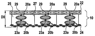
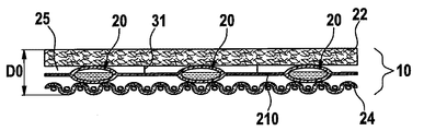
라미나 구조체는 복수 개의 공동을 포함할 수 있고 각각의 공동은 각각의 엔벨로프에 의해 봉입될 수 있다. 바람직하게는, 각 엔벨로프는 유밀식이다. 그러한 배열에서, 엔벨로프는 나란히 그리고 서로에 대해 거리를 두고 배치되게 된다.The lamina structure may comprise a plurality of cavities and each cavity may be enclosed by a respective envelope. Preferably, each envelope is oil tight. In such an arrangement, the envelopes are arranged side by side and at a distance from each other.
그러한 배열은 특히 엔벨로프 자체가 수증기 투과성이 아닌 경우에 라미나 구조체에 통기성을 제공한다. 오히려, 통기성은 엔벨로프들 사이의 공간에 의해 유지된다. 그러한 공간은 적어도 라미나 구조체의 비활성화 상태에서 형성된다. 활성화 상태에서, 엔벨로프들 사이의 공간은 바람직하게는 더 축소되지 않는데, 그 이유는 엔벨로프가 팽창되기만 하고 그 표면적을 실질적으로 증가시키지 않기 때문이다. 그러므로, 통기성은 또한 라미나 구조체의 비활성화 상태에서도 유지된다.Such an arrangement provides breathability to the lamina structure, especially when the envelope itself is not water vapor permeable. Rather, breathability is maintained by the space between the envelopes. Such space is formed at least in an inactive state of the lamina structure. In the activated state, the space between the envelopes preferably does not shrink further because the envelope only expands and does not substantially increase its surface area. Therefore, breathability is also maintained in the inactive state of the lamina structure.
엔벨로프는 패드 또는 칩의 형태를 가질 수 있고, 패드 또는 칩은 비활성화 상태에서 평탄하며, 활성화 상태에서 팽창된 베개의 형태로 형태를 변화시킨다.The envelope may take the form of a pad or chip, which is flat in the inactive state and changes shape in the form of a pillow expanded in the activated state.
본 명세서에 사용되는 바와 같이 통기성은 수증기를 라미나 구조체의 일면으로부터 다른 면으로 운반할 수 있도록 라미나 구조체, 또는 그러한 라미나 구조체를 포함하는 직물 또는 의복의 특성을 특정하는 것으로 이해된다. 일 실시예에서, 라미나 구조체는 또한 적어도 하나의 수밀식 및 수증기 투과성(통기성) 기능층을 포함할 때에 수밀식일 수 있다. 일 실시예에서, 제1 층 및/또는 제2 층이 상기 기능을 구성한다. 다른 실시예에서, 상기 기능층은 라미나 구조체의 추가 층을 형성한다. 기능층은 적절한 멤브레인, 예컨대 팽창된 폴리테트라플루오로에틸렌(PTFE)로 제조된 미소 다공질 멤브레인을 이용하여 실현될 수 있다.As used herein, breathability is understood to characterize a lamina structure, or a fabric or garment comprising such a lamina structure, so as to transport water vapor from one side of the lamina structure to the other side. In one embodiment, the lamina structure may also be watertight when it includes at least one watertight and water vapor permeable (breathable) functional layer. In one embodiment, the first layer and / or the second layer constitute this function. In another embodiment, the functional layer forms an additional layer of lamina structure. The functional layer can be realized using a suitable membrane, such as a microporous membrane made of expanded polytetrafluoroethylene (PTFE).
본 명세서에 사용되는 바와 같이 "수증기 투과성 층"이라는 용어는 층 또는 상기 라미나 구조체 또는 층상 복합재를 통한 수증기 투과를 보장하는 임의의 층을 포함하도록 의도된다. 층은 본 명세서에서 설명되는 바와 같이 직물층 또는 기능층일 수 있다. 기능층은 30(m2Pa)/W 미만의 수증기 투과 저항(Ret)으로서 측정되는 수증기 투과성을 가질 수 있다. As used herein, the term "water vapor permeable layer" is intended to include a layer or any layer that ensures water vapor transmission through the lamina structure or layered composite. The layer can be a fabric layer or a functional layer as described herein. The functional layer may have a water vapor permeability measured as a water vapor transmission resistance (Ret) of less than 30 (m 2 Pa) / W.
수증기 투과 저항 또는 내기화성 투과율(Ret)은 일정한 부분 압력 구배 하에서 소정의 영역을 통과하는 잠재적인 기화 열 플럭스를 결정하는 시트형 구조 또는 복합재의 특정한 재료 특성이다. 본 발명에 따른 라미나 구조체, 직물 복합재, 직물층 또는 기능층은 150(m2Pa)/W 미만의 수증기 투과 저항(Ret)을 갖는다면 수증기 투과성을 갖는 것으로 고려된다. 기능층은 바람직하게는 30(m2Pa)/W 미만의 Ret를 갖는다. 수증기 투과성은 ISO EN 11092(1993)에 따라 측정된다. Water vapor permeation resistance or vaporization permeability (Ret) is a specific material property of a sheet-like structure or composite that determines the potential vaporization heat flux through a given area under a constant partial pressure gradient. Lamina structures, fabric composites, fabric layers or functional layers according to the invention are considered to have water vapor permeability if they have a water vapor transmission resistance (Ret) of less than 150 (m 2 Pa) / W. The functional layer preferably has a Ret of less than 30 (m 2 Pa) / W. Water vapor permeability is measured according to ISO EN 11092 (1993).
본 명세서에 사용되는 바와 같이 "기능층"이라는 용어는 공기 침투에 대한 및/또는 소정 범위의 다른 가스의 침투, 예컨대 가스 화합물 도전에 대한 장벽을 제공하는 필름, 멤브레인 또는 코팅을 정의한다. 따라서, 기능층은 공기 불투과성 및/또는 가스 불투과성이다. 기능층은 특정한 실시예에서 공기 불투과성이지만, 다른 용례에서 공기 투과성일 수 있다.As used herein, the term "functional layer" defines a film, membrane or coating that provides a barrier to air infiltration and / or to a penetration of a range of other gases, such as gaseous compound conduction. Thus, the functional layer is air impermeable and / or gas impermeable. The functional layer is air impermeable in certain embodiments, but may be air permeable in other applications.
추가 실시예에서, 기능층은 또한 액체 물 침투에 대한, 그리고 이상적으로는 소정 범위의 액체 화합물 도전에 대한 장벽을 제공한다. 층은 적어도 0.13 bar의 압력에서 액체 물 침투를 방지한다면 액체 불투과성으로 고려된다. 물 침투 압력은 ISO 811(1981)에 대해 설명된 동일한 조건을 기초로 하여 기능층의 샘플에 관해 측정될 수 있다. In a further embodiment, the functional layer also provides a barrier to liquid water penetration and, ideally, to a range of liquid compound challenges. The layer is considered liquid impermeable if it prevents liquid water penetration at a pressure of at least 0.13 bar. The water penetration pressure can be measured on a sample of the functional layer based on the same conditions described for ISO 811 (1981).
기능층은 일 실시예에서 하나 이상의 층을 포함할 수 있고, 기능층은 공기 불투과성이지만 수증기 투과성(통기성)의 특성을 제공하도록 수증기 투과성 및 공기 불투과성이다. 바람직하게는, 멤브레인은 또한 액체 불투과성, 적어도 물 불투과성이다. The functional layer may comprise one or more layers in one embodiment, the functional layer being air impermeable but water vapor permeable and air impermeable to provide the property of water vapor permeability (breathability). Preferably, the membrane is also liquid impermeable, at least water impermeable.
본 명세서에 사용하기 위한 적절한 물 불투성 및 수증기 투과성의 가요성 멤브레인은 다공질의 팽창된 폴리테트라플루오로에틸렌(PTFE) 재료를 개시하는 미국 특허 제3,953,566호에 개시되어 있다. 팽창된 다공질 PTFE는 근모(fibril)에 의해 상호 연결되는 노드를 특징으로 하는 미소 구조를 갖는다. 원한다면, 물 불투과성은 팽창된 PTFE를 US 6,261,678호에 설명되는 바와 같이 소수성 및/또는 올레포빅(olephobic) 코팅 재료에 의해 코팅함으로써 향상될 수 있다.Suitable water impermeable and water vapor permeable flexible membranes for use herein are disclosed in US Pat. No. 3,953,566, which discloses a porous expanded polytetrafluoroethylene (PTFE) material. The expanded porous PTFE has a microstructure, characterized by nodes interconnected by fibrils. If desired, water impermeability can be enhanced by coating expanded PTFE with hydrophobic and / or olephobic coating materials as described in US Pat. No. 6,261,678.
물 불투과성 및 수증기 투과성 멤브레인은 또한 높은 분자량의 미소 다공질 폴리에틸렌 또는 폴리프로필렌, 미소 다공질 폴리우레탄 또는 폴리에스테르, 또는 폴리에테르 폴리우레탄 등의 하이드로필릭 모노리딕 폴리머와 같은 미소 다공질 재료일 수 있다.The water impermeable and water vapor permeable membrane may also be a microporous material such as a high molecular weight microporous polyethylene or polypropylene, microporous polyurethane or polyester, or hydrophilic monolithic polymers such as polyether polyurethane.
특정한 실시예에서, 라미나 구조체 및/또는 엔벨로프는 가역적 변화하도록 구성될 수 있다. 그러한 실시예에서, 가스 발생 작용제는 분해 또는 기화하고, 온도에서의 각각의 변화에 응답하여 다시 재결합 또는 응축하도록 구성된다. 활성화 사이클에서, 온도의 증가에 응답하여, 제1 층과 제2 층 사이의 거리는 (가스 발생 작용제의 비활성화 형태에서의) 제1 거리로부터 (가스 발생 작용제의 활성화 형태에서의) 제2 거리로 증가한다. 비활성화 사이클에서, 온도 감소에 응답하여, 제1 층과 제2 층 사이의 거리는 (가스 발생 작용제의 활성화 형태에서의) 제2 거리로부터 (가스 발생 작용제의 비활성화 형태에서의) 제1 거리로 감소한다. 그러한 활성화 사이클 더하기 비활성화 사이클의 순서가 수회 반복될 수 있다. In certain embodiments, lamina structures and / or envelopes can be configured to change reversibly. In such embodiments, the gas generating agent is configured to decompose or vaporize and recombine or condense again in response to each change in temperature. In the activation cycle, in response to the increase in temperature, the distance between the first layer and the second layer increases from the first distance (in the deactivated form of the gas generating agent) to the second distance (in the activated form of the gas generating agent). do. In the deactivation cycle, in response to the temperature decrease, the distance between the first layer and the second layer decreases from the second distance (in the form of activation of the gas generating agent) to the first distance (in the form of deactivation of the gas generating agent). . The sequence of such activation cycles plus deactivation cycles can be repeated several times.
엔벨로프는 활성화 후에 파열되지 않도록 의도됨으로써, 활성화 공정은 사실상 가역적이고, 수회 반복될 수 있다. 이는 사실상 가역적이고 방출된 기상 부산물(들)을 공동 내에 유지하는 가스 발생 공정을 필요로 한다(즉, 엔벨로프는 적어도 일시적으로 방출된 기체에 대해 기밀식이어야 한다). 가역적인 가스 발생 공정의 통상적인 예로는 가스 발생 작용제의 물리적인 상 변이(순수 성분 형태 또는 혼합물의 형태에서), 또는 승화 공정, 예컨대 요오드의 승화가 있다. 가역적 가스 발생 공정의 다른 예로는 예컨대 염화 암모늄의 가역적 분해가 있다.The envelope is intended not to burst after activation, so that the activation process is virtually reversible and can be repeated several times. This requires a gas generating process that is substantially reversible and keeps the released gaseous byproduct (s) in the cavity (ie the envelope must be at least airtight with respect to the gas released temporarily). Typical examples of reversible gas generation processes are physical phase shifts (in the form of pure components or mixtures) of gas generating agents, or sublimation processes, such as sublimation of iodine. Another example of a reversible gas generating process is the reversible decomposition of ammonium chloride, for example.
바람직하게는, 라미나 구조체 및/또는 엔벨로프는 가요성이고 "자가-복구 능력"을 갖는다. 따라서, 비활성화 사이클에서, 엔벨로프는 그 원래의 형태, 즉 가스 발생 작용제의 활성화가 시작되기 전의 형태를 자동적으로 복구한다. 이 공정을 지원하기 위하여 추가의 기계적 작용이 필요하지 않다. 엔벨로프의 "자가-복구 능력"은 엔벨로프의 유밀성에 의해 지원된다. 비활성화 사이클에서, 가스 발생 작용제는 일반적으로 기상으로부터 액상으로 변환할 때에 그 밀도를 증가시킨다. 그러므로, 가스 발생 작용제는 활성화 형태에서보다 비활성화 형태에서 훨씬 작은 부피를 차지하게 된다. 비활성화 사이클 중에 엔벨로프 내로 유동하는 공기가 없으면, 가스 발생 작용제의 변환은 최소 부피의 공동을 둘러싸는 (평탄한) 형태로 엔벨로프를 수축시킨다. 그러한 공정에 의해, 또한 제1 층과 제2 층 간의 거리가 가스 발생 작용제의 비활성화 형태에서의 원래의 거리로 복귀된다.Preferably, the lamina structure and / or envelope is flexible and has "self-healing capability". Thus, in the deactivation cycle, the envelope automatically restores its original form, that is, before the activation of the gas generating agent begins. No additional mechanical action is needed to support this process. The envelope's "self-healing capability" is supported by the envelope's tightness. In the deactivation cycle, the gas generating agent generally increases its density when converting from the gaseous phase to the liquid phase. Therefore, the gas generating agent occupies a much smaller volume in the inactive form than in the activated form. If no air flows into the envelope during the deactivation cycle, the conversion of the gas generating agent contracts the envelope in a (flat) form surrounding the minimum volume of cavities. By such a process, the distance between the first layer and the second layer is also returned to the original distance in the deactivated form of the gas generating agent.
전술한 바와 같이 라미나 구조체의 구성은 열에 노출시 활성화될 수 있는 개별적인 엔벨로프에 의해 둘러싸인 거시적 공동의 제공을 허용한다. 그러한 엔벨로프는 "베개" 또는 "포켓"의 형태를 가질 수 있다. 엔벨로프는 가스 발생 작용제가 비활성화 형태에 있을 때 1 mm 이상의 측방향 치수를 가질 수 있다. 특정 실시예에서, 엔벨로프는 5 mm 이상, 바람직하게는 15 mm 이상의 측방향 치수를 가질 수 있다. 통상, 엔벨로프는 1 mm 미만의 두께 치수를 가질 수 있다. 이 문맥에 사용된 측방향 치수는 대체로 가스 발생 작용제가 비활성화 형태에 있을 때 엔벨로프의 치수가 단연코 최소 치수인 폭/길이 평면, 즉 두께 방향에 직교하는 평면에서의 엔벨로프의 최소 치수를 말한다. 그러므로, 측방향 치수는 기본적으로 엔벨로프가 가스 발생 작용제의 활성화 형태에서 도달할 수 있는 최대 두께 증가를 정의한다. 라미나 구조체의 높은 통기성과 그에 따라 착용자에 대해 높은 수준의 편안함을 허용하는 평탄한 라미나 구조체(전술한 라미나 구조체)를 형성하기 위해 복수의 상기 평탄한 엔벨로프가 사용될 수 있다.As mentioned above, the construction of the lamina structure allows for the provision of a macroscopic cavity surrounded by individual envelopes that can be activated upon exposure to heat. Such envelopes may take the form of "pillows" or "pockets". The envelope may have a lateral dimension of at least 1 mm when the gas generating agent is in an inactive form. In certain embodiments, the envelope may have a lateral dimension of at least 5 mm, preferably at least 15 mm. Typically, the envelope may have a thickness dimension of less than 1 mm. The lateral dimension used in this context generally refers to the minimum dimension of the envelope in the width / length plane, i. Therefore, the lateral dimension basically defines the maximum thickness increase the envelope can reach in the activated form of the gas generating agent. A plurality of said flat envelopes can be used to form a flat lamina structure (the lamina structure described above) that allows for high breathability of the lamina structure and thus a high level of comfort for the wearer.
부피 증가에 대해 표현하자면, 공동은 가스 발생 작용제가 활성화 형태에 있을 때 가스 발생 작용제의 부피와 관련하여 10과 1000 사이의 부피 증가를 가질 수 있다. 바람직하게, 부피 증가는 40을 초과할 수 있다. Expressed for volume increase, the cavity may have a volume increase between 10 and 1000 with respect to the volume of the gas generating agent when the gas generating agent is in the activated form. Preferably, the volume increase can exceed 40.
또 다른 실시예에서, 공동을 둘러싸는 엔벨로프는 외부 엔벨로프와 내부 엔벨로프를 포함할 수 있고, 외부 엔벨로프는 외부 공동을 둘러싸고, 내부 엔벨로프는 외부 공동 내에 배치되어 공동을 둘러싼다. In another embodiment, the envelope surrounding the cavity may include an outer envelope and an inner envelope, the outer envelope surrounding the outer cavity, and the inner envelope being disposed within and surrounding the outer cavity.
전술한 라미나 구조체는 직물 복합 구조체 내로 합체될 수 있다. "직물"이란 용어는 실, 섬유 또는 필라멘트를 엮는 것에 의해 생산된 평면형 직물 구조를 말한다. 직물 구조는 직포, 부직포, 플리스(fleece) 또는 이들의 조합일 수 있다. "부직포" 직물층은 섬유 및/또는 필라멘트, 펠트, 니트, 섬유 속섬(fiber batts) 등의 망을 포함한다. "직포" 직물층은 평직(plain weave), 크로우풋 직(crowfoot weave), 바구니 문양 직(basket weave), 수자 직(satin weave), 능직(twill weave) 등과 같은 임의의 직물 직조법을 이용하여 직조된 직물이다. 평직과 능직은 업계에서 가장 보편적으로 사용되는 직조법인 것으로 믿어진다.The lamina structures described above can be incorporated into a fabric composite structure. The term "fabric" refers to a planar fabric structure produced by weaving yarn, fiber or filaments. The fabric structure can be a woven fabric, a nonwoven fabric, a fleece or a combination thereof. "Nonwoven" fabric layers include fibers and / or filaments, felts, knits, fibers batts, and the like. The "woven" fabric layer may be fabricated using any fabric weaving method, such as plain weave, crowfoot weave, basket weave, satin weave, twill weave, and the like. It is a woven fabric. Plain weave and twill are believed to be the most commonly used weaving method in the industry.
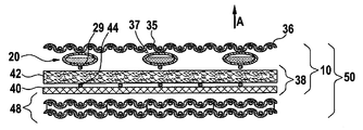
이러한 직물 복합 구조는 통상 서로에 대해 배열된 복수 개의 직물층을 포함할 것이다. 복수 개의 직물층은 외부면과 내부면을 갖는 외부 방열 쉘 구조를 포함할 수 있다. 복수 개의 직물층은 전술한 바와 같은 적응적 단열을 제공하는 라미나 구조체를 포함할 수도 있다.Such fabric composite structures will typically include a plurality of fabric layers arranged relative to one another. The plurality of fabric layers may comprise an outer heat dissipation shell structure having an outer surface and an inner surface. The plurality of fabric layers may comprise a lamina structure that provides adaptive thermal insulation as described above.
특정한 실시예에서, 적응적 단열을 제공하는 라미나 구조체는 외부 방열 쉘 구조의 내부면에 배치될 수 있다.In certain embodiments, a lamina structure that provides adaptive thermal insulation can be disposed on an inner surface of an outer heat dissipation shell structure.
소정의 실시예로서, 외부 방열 쉘 구조는 1차적으로 방염을 제공하는 제품(예, 의복)의 외층을 지시한다. 외부 방열 쉘 구조는 예컨대, 폴리이미드(메타-아라미드, 파라-아라미드) 또는 이들의 혼합물과 같은 난연 직물을 포함하는 직포, 니트 또는 부직포 직물 등의 난연성 내열 직물을 포함할 수 있다. 난연성 또는 내열성 직물의 특정 예로는 폴리벤지미다졸(PBI) 섬유; 폴리벤족사졸(PBO) 섬유; 폴리 디이미다조 피리디닐렌 디히드록시 페닐렌(PIPD); 모다크릴릭 섬유; E.I. DuPont de Nemours, Inc에 의해 상표명 Nomex®로 시판되는 폴리(메타페닐렌 이소프탈아미드); E.I. DuPont de Nemours, Inc에 의해 상표명 Kevlar®로 시판되는 폴리(파라페닐렌 테레프탈아미드); 멜라민; 방염(FR) 코튼; FR 라이온; PAN(폴리 아크릴니트릴)을 포함한다. 전술한 섬유 중 하나 이상을 포함하는 직물(예, Normex®/Kevlar®)도 사용될 수 있다. 일 실시예에서, 직조된 Normex®Delta T(200 g/m2의 직물 중량)로 제조된 외부 쉘 층이 사용된다.In some embodiments, the outer heat dissipation shell structure primarily dictates the outer layer of the product (eg, a garment) providing flame retardancy. The outer heat dissipation shell structure may include flame retardant heat resistant fabrics, such as woven, knitted or nonwoven fabrics, including flame retardant fabrics such as, for example, polyimide (meta-aramid, para-aramid) or mixtures thereof. Specific examples of flame retardant or heat resistant fabrics include polybenzimidazole (PBI) fibers; Polybenzoxazole (PBO) fibers; Poly diimidazo pyridinylene dihydroxy phenylene (PIPD); Modacrylic fibers; Poly (metaphenylene isophthalamide) sold under the name Nomex® by EI DuPont de Nemours, Inc; Poly (paraphenylene terephthalamide) sold under the trade name Kevlar® by EI DuPont de Nemours, Inc; Melamine; Flame retardant (FR) cotton; FR Lion; PAN (poly acrylonitrile). Fabrics comprising at least one of the foregoing fibers (eg Normex® / Kevlar®) can also be used. In one embodiment, an outer shell layer made of woven Normex®Tel T (fabric weight of 200 g / m 2 ) is used.
불연성 재료는 국제 표준 EN ISO 15025(2003)에서 특정된다. DIN EN ISO 14116(2008)은 재료의 불연성을 평가하기 위한 시험 방법을 특정한다. DIN EN ISO 14116(2008)에 따르면, 불연성의 다른 레벨들이 특정된다. 예를 들면, 소방복에 사용되는 불연성 재료는 DIN EN ISO 14116(2008)의 레벨 3에 대해 특정된 시험 절차를 통과하는 것이 필요하다. 다른 용례의 경우 레벨 1과 2에 대해 특정된 바와 같이 덜 엄격한 기준이면 충분할 수 있다.Non-combustible materials are specified in the international standard EN ISO 15025 (2003). DIN EN ISO 14116 (2008) specifies test methods for evaluating the incombustibility of materials. According to DIN EN ISO 14116 (2008), different levels of incombustibility are specified. For example, non-combustible materials used in fire suits need to pass the test procedures specified for level 3 of DIN EN ISO 14116 (2008). For other applications, less stringent criteria may be sufficient, as specified for levels 1 and 2.
직물은 장벽 구조도 포함할 수 있다. 일 실시예에서, 장벽 구조는 외부 방열 쉘 구조의 내부면에 배치될 것이다.The fabric may also include a barrier structure. In one embodiment, the barrier structure will be disposed on the inner face of the outer heat dissipation shell structure.
특정 용례에서, 장벽 구조는 적어도 하나의 기능층을 포함한다. 상기 기능층은 수증기 투과성 및 방수일 수 있고, 적어도 하나의 수증기 투과성 및 방수 멤브레인을 포함한다. In certain applications, the barrier structure includes at least one functional layer. The functional layer may be water vapor permeable and waterproof, and includes at least one water vapor permeable and waterproof membrane.
장벽 구조는 액체 장벽으로서 기능하지만 수증기가 장벽을 통과하도록 할 수 있는 성분이다. 소방수 출동복과 같은 의복에서, 이러한 장벽 구조는 의복 내로 물이 접근되지 않게 함으로써 소방수가 부담하는 무게를 최소화한다. 추가로, 장벽 구조는 고온 환경에서 작업시 중요한 기능으로서 수증기(땀)가 배출되도록 한다. 통상, 장벽 구조는 부직포 또는 직포와 같은 적어도 하나의 직물층에 적층되는 멤브레인을 포함한다. 적어도 하나의 직물층에 적층되도록 사용되는 멤브레인 재료(라미네이트 항목에서도 알 수 있음)는 팽창된 폴리테트라플루오로에틸렌(PTFE), 폴리우레탄 및 그 조합을 포함한다. 이러한 라미네이트에 대한 상업적으로 구매 가능한 예로는 부직포 또는 직포 금속-아라미드 직물 상에 CROSSTECH®이란 상표명의 수분 장벽 라미네이트 또는 Neoprene® 멤브레인으로 입수 가능한 라미네이트를 포함한다.The barrier structure acts as a liquid barrier but is a component that allows water vapor to pass through the barrier. In garments, such as fireman uniforms, this barrier structure minimizes the weight of the fireman by preventing water from entering the garment. In addition, the barrier structure allows water vapor (sweat) to be released as an important function when working in high temperature environments. Typically, the barrier structure comprises a membrane laminated to at least one fabric layer, such as a nonwoven or woven fabric. Membrane materials used to be laminated to at least one fabric layer (also found in the laminate section) include expanded polytetrafluoroethylene (PTFE), polyurethane, and combinations thereof. Commercially available examples for such laminates include laminates available as a moisture barrier laminate or Neoprene® membrane under the trade name CROSSTECH® on nonwoven or woven metal-aramid fabrics.
일 실시예에서, EP 0 689 500 B1호에 기술된 바와 같이 제조된 팽창된 PTFE(ePTFE)의 멤브레인을 포함하는 장벽 구조가 사용된다. 장벽 층은 90 g/m2의 직물 중량을 갖는 부직포 아라미드 직물(15%의 파라-아라미드와 85%의 금속-아라미드)로 이루어진 직물층에 부착될 수 있다. 이러한 장벽 구조는 GORE-TEX®Fire-blocker N이란 상표명으로 상업적으로 구매 가능하다. 다른 실시예에서, CROSSTECH®/Nomex®PJ 수분 장벽이란 상표명으로 구매 가능한 장벽 구조가 사용된다. 이러한 수분 장벽 구조는 폴리아미드 직물(Nomex®IIIA)에 부착된 폴리우레탄 층을 갖는 ePTFE 필름을 포함한다. 예컨대 US 4 493 870, US 4 187 390 또는 US 4 194 041에 기술된 바와 같은 다른 장벽이 사용될 수 있다.In one embodiment, a barrier structure is used which comprises a membrane of expanded PTFE (ePTFE) prepared as described in EP 0 689 500 B1. The barrier layer can be attached to a fabric layer consisting of nonwoven aramid fabric (15% para-aramid and 85% metal-aramid) with a fabric weight of 90 g / m 2 . Such barrier structures are commercially available under the trade name GORE-TEX® Fire-blocker N. In another embodiment, a barrier structure available under the trade name CROSSTECH® / Nomex®PJ Moisture Barrier is used. This moisture barrier structure includes an ePTFE film with a polyurethane layer attached to a polyamide fabric (Nomex® IIIA). Other barriers may be used, for example as described in US 4 493 870, US 4 187 390 or US 4 194 041.
예컨대, 가스, 액체 및/또는 에어로졸 형태의 화학적 화합물 또는 가스, 액체 및/또는 에어로졸 형태의 생물학적 물질을 포함하는 물질과 같은 가스 및/또는 액체의 투과를 방지하는 적어도 하나의 기능층을 제공하는 장벽과 같이, 수분 장벽이 아닌 장벽을 고려해볼 수 있다. 특정 실시예에서, 이러한 다른 장벽층도 마찬가지로 통기성을 가질 수 있다.A barrier that provides at least one functional layer that prevents permeation of a gas and / or liquid, such as, for example, a chemical compound in gas, liquid and / or aerosol form or a material comprising a biological material in gas, liquid and / or aerosol form As such, barriers that are not moisture barriers can be considered. In certain embodiments, these other barrier layers may likewise be breathable.
장벽 구조는 외부 방열 쉘 구조와 적응적 단열을 제공하는 라미나 구조체 사이에 위치될 수 있다. The barrier structure may be located between the outer heat dissipation shell structure and the lamina structure to provide adaptive insulation.
직물은 예컨대, 착용자를 환경적 영향으로부터 보호하는 것이 필요하거나 주어진 환경적 조건하에서 원하는 기능적 특성을 제공하는 것이 필요한 소방, 법률적 집행, 군사 또는 산업적 작업 등의 용례에 통상적으로 사용되는 방호복 또는 기능복에 사용될 수 있다. 이러한 의복은 착용자를 열, 화염, 또는 액체에 의한 충격으로부터 보호하는 것이 필요할 수 있다. 통상, 이러한 의복은 착용자가 자신이 행하여야 할 작업을 행할 수 있게 착용자에게 충분한 편안함을 제공하는 것이 바람직하다.Fabrics are, for example, protective or functional clothing commonly used in applications such as firefighting, law enforcement, military or industrial work, which need to protect the wearer from environmental influences or provide the desired functional properties under given environmental conditions. Can be used for Such garments may need to protect the wearer from heat, flame, or liquid shocks. Typically, such garments are desirable to provide the wearer with sufficient comfort to allow the wearer to do the work they are supposed to do.
특히, 직물은 화재/열 방호복에 사용되도록 되는 것이 의도된다.In particular, the fabric is intended to be used in fire / heat protective clothing.
본 발명의 예시적인 실시예들은 실시예들을 예시하는 첨부 도면을 참조하여 하기에 상세히 설명될 것이다.
도 1a는 일 실시예의 엔벨로프를 형성하는 데에 사용되는 층에 대한 단순화된 개략적인 단면도를 보여주고;
도 1b는 엔벨로프를 형성하는 데에 사용되는 추가의 층에 대한 단순화된 개략적인 단면도를 보여주며;
도 2a 내지 도 2c는 엔벨로프를 제조하는 방법을 보여주고;
도 2d는 복수 개의 단일 엔벨로프를 보여주며;
도 2e 내지 도 2g는 복수 개의 상호 연결된 단일 엔벨로프를 포함하는 시트층 구조의 여러 실시예를 보여주고;
도 3a는 일 실시예에 따른 가스 발생 작용제를 포함하는 공동을 둘러싸는 엔벨로프의 단순화된 개략적인 단면도를 보여주는데, 엔벨로프 라미네이트층은 엔벨로프를 형성하도록 서로 용접되며;
도 3b는 도싱 에이드(dosing aid)에 적용되는 가스 발생 작용제를 포함하는 추가 실시예에 따른, 공동을 둘러싸는 엔벨로프의 단순화된 개략적인 단면도를 보여주며;
도 3c는 용접 가능한 도싱 에이드층에 적용되는 가스 발생 작용제를 포함하는 추가 실시예에 따른, 공동을 둘러싸는 엔벨로프의 단순화된 개략적인 단면도를 보여주고;
도 3d는 추가 실시예에 따른 엔벨로프의 단순화된 개략적인 단면도를 보여주는데, 엔벨로프는 가스 발생 작용제를 각각 포함하는 2개의 공동을 둘러싸며;
도 4a는 상하로 함께 접합되는 추가 실시예에 따른 2개의 동일한 엔벨로프의 개략도를 보여주고;
도 4b는 상하로 함께 접합되는 추가 실시예에 따른 상이한 형태의 2개의 엔벨로프의 추가 개략도를 보여주며;
도 4c는 측방향 단부들 중 하나에서 함께 접합되는 추가 실시예에 따른 2개의 엔벨로프의 추가 개략도를 보여주고;
도 5a는 비활성된 상태로 추가 실시예에 따른 엔벨로프의 단순화된 개략적인 단면도를 보여주며;
도 5b는 활성화 상태로 추가 실시예에 따른 엔벨로프의 단순화된 개략적인 단면도를 보여주고;
도 6a는 비활성된 상태로 제1 층과 제2 층 사이에 위치 결정되는 복수 개의 엔벨로프가 형성되는 일 실시예에 따른 라미나 구조체의 단순화된 개략적인 단면도를 보여주며;
도 6b는 활성화 상태로 도 5a에 도시된 실시예의 라미나 구조체의 단순화된 개략적인 단면도를 보여주고;
도 7a는 비활성화 상태로 제1 층과 제2 층 사이에 위치 결정되는 복수 개의 엔벨로프를 갖는 추가 실시예에 따른 라미나 구조체의 단순화된 개략적인 단면도를 보여주며;
도 7b는 비활성화 상태로 제1 층과 제2 층 사이에 위치 결정되는 복수 개의 엔벨로프를 갖는 추가 실시예에 따른 라미나 구조체의 단순화된 개략적인 단면도를 보여주고;
도 7c는 비활성화 상태로 제1 층과 제2 층 사이에 위치 결정되는 복수 개의 엔벨로프를 갖는 추가 실시예에 따른 라미나 구조체의 단순화된 개략적인 단면도를 보여주며;
도 7d는 비활성화 상태로 제1 층과 제2 층 사이에 위치 결정되는 복수 개의 엔벨로프를 갖는 추가 실시예에 따른 라미나 구조체의 단순화된 개략적인 단면도를 보여주고;
도 7e는 비활성화 상태에서 제1 층과 제2 층 사이에 위치 결정되는 "엔벨로프의 메시"의 형태로 복수 개의 엔벨로프를 갖는 추가 실시예에 따른 라미나 구조체의 단순화된 개략적인 단면도를 보여주며;
도 7f는 비활성화 상태에서 제1 층과 제2 층 사이에 위치 결정되는 복수 개의 엔벨로프와, 제1 및 제2 층 중 하나의 층 위에 적층되는 추가 기능 멤브레인을 갖는 추가 실시예에 따른 라미나 구조체의 단순화된 개략적인 단면도를 보여주고;
도 8a는 도 7a에 도시된 라미나 구조체를 포함하는 직물의 단순화된 개략적인 단면도를 보여주며;
도 8b 내지 도 8g는 본 발명에 따라 적응적 단열을 제공하는 라미나 구조체를 포함하는 직물의 다른 가능한 형태를 보여주고;
도 9는 도 8a에 예시된 직물을 포함하는 소방수 자켓을 보여주며;
도 10은 라미나 구조체가 비활성화 상태로부터 활성화 상태로 전환될 때 제1 층과 제2 층 사이의 거리의 증가를 측정하는 장치의 개략적 스케치를 보여주고;
도 11은 라미나 구조체가 비활성화 상태로부터 활성화 상태로 전환될 때 제1 층과 제2 층 사이의 거리의 증가를 측정하기 위한 라미나 구조체 시험편의 개략적 스케치를 보여주며;
도 12는 가역적으로 복수 개의 활성화/비활성화 사이클을 경험하도록 구성된 라미나 구조체에 대한 기능성 시험의 결과를 개략적으로 보여준다. Exemplary embodiments of the invention will be described in detail below with reference to the accompanying drawings which illustrate embodiments.
1A shows a simplified schematic cross-sectional view of a layer used to form an envelope of one embodiment;
1b shows a simplified schematic cross-sectional view of an additional layer used to form an envelope;
2A-2C show a method of making an envelope;
2D shows a plurality of single envelopes;
2E-2G show various embodiments of a sheet layer structure comprising a plurality of interconnected single envelopes;
3A shows a simplified schematic cross-sectional view of an envelope surrounding a cavity comprising a gas generating agent according to one embodiment, where the envelope laminate layers are welded to each other to form an envelope;
3B shows a simplified schematic cross-sectional view of an envelope surrounding a cavity according to a further embodiment including a gas generating agent applied to a dosing aid;
3C shows a simplified schematic cross-sectional view of an envelope surrounding a cavity, in accordance with a further embodiment including a gas generating agent applied to the weldable dosing aid layer;
3d shows a simplified schematic cross-sectional view of an envelope according to a further embodiment, the envelope surrounding two cavities each containing a gas generating agent;
4A shows a schematic of two identical envelopes according to further embodiments joined together up and down;
4B shows a further schematic illustration of two envelopes of different types according to further embodiments joined together up and down;
4C shows a further schematic illustration of two envelopes according to a further embodiment bonded together at one of the lateral ends;
5A shows a simplified schematic cross-sectional view of an envelope according to a further embodiment in an inactive state;
5b shows a simplified schematic cross-sectional view of an envelope according to a further embodiment in an activated state;
FIG. 6A shows a simplified schematic cross-sectional view of a lamina structure according to one embodiment where a plurality of envelopes are positioned between the first and second layers in an inactive state; FIG.
6B shows a simplified schematic cross-sectional view of the lamina structure of the embodiment shown in FIG. 5A in an activated state;
FIG. 7A shows a simplified schematic cross-sectional view of a lamina structure according to a further embodiment having a plurality of envelopes positioned between the first and second layers in an inactive state; FIG.
7B shows a simplified schematic cross-sectional view of a lamina structure according to a further embodiment with a plurality of envelopes positioned between the first and second layers in an inactive state;
7C shows a simplified schematic cross-sectional view of a lamina structure according to a further embodiment with a plurality of envelopes positioned between the first and second layers in an inactive state;
7D shows a simplified schematic cross-sectional view of a lamina structure according to a further embodiment with a plurality of envelopes positioned between the first and second layers in an inactive state;
7E shows a simplified schematic cross-sectional view of a lamina structure according to a further embodiment having a plurality of envelopes in the form of a “mesh of envelopes” positioned between the first and second layers in an inactive state;
FIG. 7F illustrates a lamina structure according to a further embodiment with a plurality of envelopes positioned between the first and second layers in an inactive state and an additional functional membrane stacked over one of the first and second layers. Shows a simplified schematic cross section;
FIG. 8A shows a simplified schematic cross-sectional view of a fabric comprising the lamina structure shown in FIG. 7A;
8B-8G show another possible form of a fabric comprising a lamina structure that provides adaptive thermal insulation in accordance with the present invention;
9 shows a firefighter jacket including the fabric illustrated in FIG. 8A;
10 shows a schematic sketch of an apparatus for measuring an increase in the distance between a first layer and a second layer when the lamina structure is switched from an inactive state to an activated state;
11 shows a schematic sketch of a lamina structure test piece for measuring an increase in the distance between a first layer and a second layer when the lamina structure is switched from an inactive state to an activated state;
12 schematically shows the results of a functional test on a lamina structure configured to reversibly experience multiple activation / deactivation cycles.
모든 도면에서 동일하거나 대응하는 기능을 갖는 각각의 실시예의 구성 성분들은 각각 동일한 참조 번호로 지시된다. 다음의 설명에서 이러한 구성 성분들은 해당 성분을 포함하는 실시예 중 첫 번째 실시예에 대해서만 설명된다. 동일한 구성 성분이 포함되고 동일한 참조 번호로 지시된 각각의 후속하는 실시예에 동일한 설명이 적용되는 것으로 이해하여야 한다. 무엇이든 반대로 언급되지 않는 한, 통상 각각의 이전 실시예에서 해당 구성 성분의 대응하는 설명을 참조한다.The components of each embodiment having the same or corresponding function in all the drawings are each denoted by the same reference numerals. In the following description these components are described only for the first embodiment of the embodiment that includes those components. It is to be understood that the same description applies to each subsequent embodiment in which the same components are included and indicated by the same reference numerals. Unless anything is stated to the contrary, reference is generally made to the corresponding description of the corresponding component in each previous embodiment.
도 1a는 일 실시예에 따른 층(8)의 단순화된 개략적 단면도를 보여준다. 이러한 층(8)은 엔벨로프를 제공하도록 사용될 수 있다. 층(8)은 커버층(8a), 유밀성 층(8b) 및 밀봉층(8c)을 포함하는 라미네이트이다. 일례에서, 층은 폴리에틸렌 테레프탈레이트(PET)-커버층(8a), 알루미늄(Al)-유밀성 층(8b), 및 폴리에틸렌(PE)-밀봉층(8c)을 포함하는 알루미늄/플라스틱 복합 재료로 제조된다. 충분한 유밀성(fluid tightness)을 제공하기 위하여, Al-층(8b)에 대한 적당한 두께 범위는 4 ㎛ 내지 25 ㎛이다. 도시된 실시예에서, Al-층(8b)은 적어도 12 ㎛의 두께를 갖는다. PE-층(8c)은 인접한 라미네이트층(8)이 엔벨로프를 형성하도록 함께 유밀식으로 접합될 수 있는 밀봉층으로서 사용된다. PE-층(8c)의 두께는 20 ㎛ 내지 60 ㎛일 수 있다. 바람직한 두께는 약 40 ㎛이다. PET-층(8a)은 엔벨로프의 외표면에 원하는 특성을 제공하도록 커버층으로서 사용될 수 있다. 실시예에서, 12 ㎛ 두께의 PET-층(8a)이 사용된다. 설명된 라미네이트층(8)은 독일의 Kobusch-Sengewald GmbH사로부터 얻을 수 있다. 1a shows a simplified schematic cross-sectional view of layer 8 according to one embodiment. This layer 8 can be used to provide an envelope. The layer 8 is a laminate comprising a
엔벨로프를 형성하기 위한 대안적인 층(8)이 도 1b에 도시되어 있다. 이 층(8)은 또한 40 ㎛의 두께를 갖는 PE로 제조된 커버층(8a), 적어도 12 ㎛의 두께를 갖는 Al 층(8b), 및 40 ㎛의 두께를 갖는 PE 밀봉층(8c)을 포함하는 라미네이트이다. 이 실시예에서, 커버층(8a)은 밀봉층(8c)과 동일한 재료로 제조된다. 커버층(8a)이 추가의 밀봉층으로서 사용될 수 있다. An alternative layer 8 for forming the envelope is shown in FIG. 1B. This layer 8 also includes a
도 3a는 가스 발생 작용제(전체적으로 18로 지시됨)를 포함하는 공동(16)을 둘러싸는 엔벨로프(전체적으로 20으로 지시됨)의 단순화된 개략적인 단면도를 보여준다. 도 3a에서, 뿐만 아니라 도 3b, 3c, 3d, 4a, 4b, 4c 각각에서, 엔벨로프(20)는 가스 발생 작용제(18)가 비활성화 형태로 도시되고, 이에 따라 엔벨로프(20)는 비활성화 상태로서도 지칭되는 팽창되지 않은, 기본적으로 평탄한 형태를 갖는다. 도 3a 내지 도 3d 및 도 4a 내지 도 4c에 도시된 평탄한 형태에서, 엔벨로프(20)는 두께 방향에 직교하는 엔벨로프(20)의 방향, 즉 측방향에서의 치수보다 상당히 작은 두께 방향에서의 치수를 갖는다. 두께 방향에서 엔벨로프(20)의 치수는 도 3a 내지 도 4c에서 d로 지시된다. 측방향에서의 엔벨로프(20)의 치수는 도 3a 내지 도 4c에서 A0로 지시된다. 여기서, A0는 엔벨로프(20)의 용접부의 일단부에서 대향 단부까지의 길이를 가리킨다. 엔벨로프(20)가 대체로 "둥근" 또는 사각형 형태를 갖는 실시예에서, 엔벨로프의 치수(A0)는 모든 측방향에서 실질적으로 동일할 수 있다. 대체로 세장형 형태를 갖는 엔벨로프의 실시예에서, 폭 방향의 치수(A0)는 길이 방향에서의 치수(A0)보다 작을 수 있다. FIG. 3A shows a simplified schematic cross-sectional view of an envelope (indicated generally at 20) surrounding a
일 실시예에서, 엔벨로프(20)는 2개의 엔벨로프 층(12, 14)으로 제조된다. 엔벨로프 층(12, 14)은 도 1a 또는 도 1b에 도시된 층(8)과 같은 형태를 각각 가질 수 있다. 특히, 명확하게 도시하지 않았지만, 엔벨로프 층(12, 14)은 도 1a 또는 도 1b에 도시된 층(8)에 대응하게 3개의 층으로 각각 제조될 수 있다. 엔벨로프 층(12)은 엔벨로프(20)의 상부를 형성하고, 그러한 상부는 공동(16)의 상부를 둘러싼다. 엔벨로프 층(14)은 엔벨로프(20)의 하부를 형성하고, 그러한 하부는 공동(16)의 하부를 둘러싼다. 도시된 실시예에서, 엔벨로프 층(12)과 엔벨로프 층(14)은 동일한 형태, 예컨대 도 1a에 도시된 층(8)의 형태를 갖는다. 엔벨로프(20)는 최내측 밀봉층, 중간 유밀성 층, 및 외측 커버층을 갖는다.In one embodiment, the
대안적으로, 엔벨로프(20)는 도 1b에 도시된 층(8)으로부터 구성된 2개의 엔벨로프 층(12, 14)으로 이루어질 수 있거나, 도 1a에 도시된 층(8)으로부터 구성된 하나의 엔벨로프 층(12)과 도 1b에 도시된 층(8)으로부터 구성된 하나의 엔벨로프 층(14)으로 이루어질 수 있다. 재료 자체가 유밀식이고 유밀식 엔벨로프(20)가 생성되도록 유밀식으로 함께 접합된다면, 대안적인 재료, 특히 더 복잡하거나 덜 복잡한 형태의 단층 또는 라미네이트층이 엔벨로프(20)를 제조하는 데에 사용될 수 있다. 일 실시예에서, 엔벨로프 층은 유밀식 단일층(단층)으로 제조될 수 있다. 상기 층은 용접 또는 접착에 의해 엔벨로프로 형성될 수 있다.Alternatively,
엔벨로프(20)는 가스 발생 작용제(18)가 채워지는 공동(16)을 둘러싼다. 가스 발생 작용제(18)는 실온에서 적절한 평형 상태의 증기압을 갖는 액체가 되도록 선택된다. 실온은 가스 발생 작용제(18)의 비활성화 형태를 규정하도록 고려될 수 있다. 도 3a에 도시된 가스 발생 작용제(18)의 비활성화 형태에서, 가스 발생 작용제(18)는 실질적으로 18'로 지시된 액상으로 존재한다. 엔벨로프(20)는 공동(16)의 실질적으로 유밀식 밀폐구를 제공하고, 이에 따라 공동(16)은 충분한 양의 가스 발생 작용제(18)를 수용하며, 공동(16)의 나머지 부피는 가스로 채워지고, 특히 가스 발생 작용제(18)가 채워질 때에 공동(16) 내에 둘러싸인 공기 또는 기타 가스의 나머지 양으로 채워진다. 개시된 실시예에서, 가스 발생 작용제(18)는 화학식 CF3CF2C(O)CF(CF3)2를 갖는 유체이다. 그러한 유체는 통상 불을 소화하는 데에 사용되고 3M사로부터 상표명 "Novec® 1230 소화액"으로 시판 중이다. 전술한 바와 같이, 기타 유체가 가스 발생 작용제에 대해 사용될 수 있다.
도 3a에 도시된 엔벨로프(20)를 제조하는 제1 방법은 아래와 같다:
A first method of manufacturing the
제1 밀봉 단계:First sealing step:
도 1a 또는 도 1b에 따른 재료로 제조된 2개의 엔벨로프 층(12, 14)은 서로 상하로 놓여지고, 그 각각의 밀봉층이 서로 대면한다. 사각형 엔벨로프(20)를 형성하기 위하여, 밀봉층들을 접촉시키고 밀봉층들을 함께 용접하도록 고온의 바아(밀봉 폭: 2 mm)가 엔벨로프 층(12, 14)과 접촉하게 된다. 이 절차는 사각형 엔벨로프(20)의 4면들 중 3개의 면에 대해 행해진다. 따라서, 1면이 개방된 엔벨로프(20)가 형성된다.
The two envelope layers 12, 14 made of the material according to FIG. 1A or 1B are placed on top of each other, with their respective sealing layers facing each other. To form the
충전 단계:Charging stage:
엔벨로프(20)를 정밀 저울 위에 놓고 예컨대 주사기 바늘을 이용하여 가스 발생 작용제(18)를 엔벨로프 내에 충전한다. 충전될 가스 발생 작용제의 양은 저울에 의해 조절된다.
The
일례: 엔벨로프(20)가 아래의 특성을 갖는 경우에, 0.07 g의 양의 가스 발생 작용제(18)가 엔벨로프(20) 내에 충전된다: 엔벨로프(20)가 전술한 바와 같이 PEt/Al/PE로 제조된 2개의 엔벨로프 층(12, 14)으로 형성되고, 엔벨로프(20)의 외부 크기는 20 mm의 길이와 20 mm의 폭[16 mm의 길이와 16 mm의 폭의 공동의 내부 크기에 대응함]이며, 가스 발생 작용제(18)는 Novec® 1230으로 선택된다.
Example: If the
제2 밀봉 단계:Second sealing step:
충전 단계가 완료된 후에, 엔벨로프(20)의 개방면이 제4의 2 mm 밀봉선에 의해 폐쇄된다. 이어서, 엔벨로프(20)는 밀봉선을 따라 정밀하게 절단된다.After the filling step is completed, the open face of the
전술한 바와 같이 제조되는 엔벨로프의 충전량의 정확도는 아래와 같이 측정될 수 있다:The accuracy of the filling amount of the envelope manufactured as described above can be measured as follows:
예정된 양의 엔벨로프(20)(예컨대, 10개의 엔벨로프)가 제1 밀봉 단계에 따라 제조되고, 이들 엔벨로프(20) 각각은 마킹되고 개별적으로 4 자리 저울(예컨대, Satorius BP121S)에서 계량된다. 액체 형태의 예정된 양의 가스 발생 작용제(18)는 시간 트리거식 밸브를 비롯하여 중력 이송 저장조로부터 파이프를 통해, 엔벨로프의 내부로 주사기 바늘을 통해 주입된다. 예정된 밸브 개방 시간이 조절 가능한 전기 타이머에 의해 보장된다. 각 엔벨로프(20)는 제2 밀봉 단계에 의해 즉시 폐쇄된다. 충전된 엔벨로프(20) 각각은 계량되고, (충전 전에 측정된) 빈 엔벨로프(20)의 중량을 감산한다. 샘플 세트의 평균값으로부터 ±10%의 최대 편차가 달성 가능해야 한다. A predetermined amount of envelope 20 (eg 10 envelopes) is produced according to the first sealing step, each of which is marked and individually weighed on a four digit scale (eg Satorius BP121S). A predetermined amount of
도 3a에 따른 엔벨로프(20)를 제조하는 제2 방법이 도 2a 내지 도 2d에 도시되고, 아래와 같다:
A second method of manufacturing the
제1 단계(도 2a)First step (Figure 2a)
도 1a에 따라 라미네이트 재료(8)로 제조되는 세장형 시트, 예컨대 65 mm의 폭과 1.3 m의 길이를 갖는 시트가 사용된다. 대안적으로, 상이한 크기로 된 및/또는 라미네이트 재료로 제조된, 예컨대 도 1b에 도시된 라미네이트 재료(8)로 제조된 시트가 사용될 수 있다. 시트는 라미네이트(8)(도 1a 또는 도 1b 참조)의 커버층(8a)이 외측에 배치되고, 밀봉층(8c)이 내측에 배치되도록 장변을 따라 절곡된다. 이에 따라, 엔벨로프 층(12, 14)의 밀봉층들이 서로 대면하도록 상부 엔벨로프 층(12)과 하부 엔벨로프 층(14)이 형성된다. 이 방식으로, 예비 엔벨로프(101)가 생성된다. 예비 엔벨로프(101)는 32.5 mm의 폭과 1.3 m의 길이를 갖는다. 예비 엔벨로프(101)는 그 하나의 장변(102)이 폐쇄되고 그 대향 장변(103)을 따라 개방된다. 예비 엔벨로프(101)의 단변(104, 105)은 모두 개방된다.
An elongate sheet made of laminate material 8 according to FIG. 1A is used, for example a sheet having a width of 65 mm and a length of 1.3 m. Alternatively, sheets of different sizes and / or made of laminate material, for example made of laminate material 8 as shown in FIG. 1B can be used. The sheet is bent along the long side so that the
제2 단계(도 2b)Second Step (Figure 2b)
회전 초음파 용접 휠(예컨대, 5 mm의 폭)이 예비 엔벨로프(101)와 개방된 장변(103)에서 접촉하여, 엔벨로프 층(12, 14)의 2개의 밀봉층을 서로 접촉하게 한다. 밀봉층은 예비 엔벨로프(101)의 개방된 장변(103)에 평행하게 연장되는 밀봉선(106)을 따라 연속적으로 함께 용접된다. 따라서, 장변(103)이 폐쇄되고 예비 엔벨로프(101)가 2개의 개방된 장변(104, 105)을 갖는 관형 형태를 갖는다. 고온의 밀봉 바아(밀봉 폭: 2 mm)가 단변(105) 중 하나에서 예비 엔벨로프(101)과 접촉하여 밀봉층들을 서로 접촉하게 한다. 밀봉층들은 단변(105)에 평행하게 연장되는 밀봉선(107)을 따라 함께 용접되어 예비 엔벨로프(101)를 단변(105)에서 폐쇄한다. 이후에, 예비 엔벨로프(101)는 일단부가 폐쇄된 튜브의 형태를 갖는다.A rotating ultrasonic welding wheel (eg, 5 mm wide) contacts the
이어서, 개방된 단변(104)을 폐쇄된 단변(105)보다 높게 유지하고, 개방된 단변(104)을 통해 가스 발생 작용제(18)를 개방된 관형 예비 엔벨로프(101) 내로 충전한다. 일례로서, 전술한 바와 같이 23 mm의 폭과 1 m의 길이의 내부 크기를 갖는 공동을 형성하는 예비 엔벨로프(101)의 경우, 예비 엔벨로프(101)는 전술하고 도 1a에 도시된 바와 같이 PET/Al/PE로 제조된 라미네이트층(8)으로 제조되고, 전술한 바와 같이 Novec® 1230으로서 공지된 액체인 가스 발생 작용제(18)의 경우, 4 ml의 양의 가스 발생 작용제(18)가 예비 엔벨로프(101) 내에 충전된다.
The open
제3 단계(도 2c)Third step (Figure 2c)
예비 엔벨로프(101)는 그 개방된 단변(104)이 상방을 향한 상태로 유지되고, 직립 자세로 유지되어, 공동 내에 충전된 가스 발생 작용제(18)는 예비 엔벨로프(101)의 폐쇄된 단변(105)에 집중된다. 폐쇄된 단변(105)에서 시작하여, 예비 엔벨로프(101)는 제2 회전 초음파 용접 휠(110)과 긴밀하게 접촉한다. 용접 휠(110)은 한쌍의 용접 휠(110, 111)을 갖는 초음파 용접 기계의 부품이다. 용접 휠(110)은 복수 개의 원주 방향 시일 윤곽(114A, 114B,...)이 형성된 원주면(112)을 갖는다. 각 시일 윤곽(114A, 114B,...)은 제조될 엔벨로프(20A, 20B,...; 도 2d)의 밀봉선의 형태에 대응하는 형태를 갖는다. 이 구성에서, 용접 휠(111)은 평면형 원주면을 갖는다.The
예비 엔벨로프(101)는 폐쇄된 단변(105)에서 시작하여 한쌍의 용접 휠(110, 111)을 통해 운반된다[예비 엔벨로프(101)의 이동 방향을 가리키는 도 2c의 화살표 B 참조). 이 방식에서, 용접 휠(110)은 먼저 예비 엔벨로프(101)의 폐쇄된 단변(105)과 접촉하고 최종적으로 예비 엔벨로프(101)의 개방된 단변(104)과 접촉한다.The
용접 휠(110)이 예비 엔벨로프(101)와 접촉할 때에, 가스 발생 작용제(18)는 밀봉 윤곽(114A, 114B) 중 하나가 예비 엔벨로프(101)와 접촉하게 되는 영역에서 회전 초음파 용접 휠(110, 111)에 의해 멀리 압박되는데, 그 이유는 그러한 영역에서, 밀봉층이 서로 접촉하고 함께 용접되기 때문이다. 이 방식에서, 최종 엔벨로프(20A; 도 2d)의 밀봉부를 형성하는 폐쇄된 밀봉 윤곽(116A)이 예비 엔벨로프(101)에 형성된다.When the
예비 엔벨로프(101)가 회전 용접 휠(110, 111) 사이의 간극을 통해 이동할 때에, 복수 개의 연속적인 밀봉 윤곽(116A, 116B,...)이 예비 엔벨로프(101)에 형성된다. 각 밀봉 윤곽(116A, 116B,...)은 예정된 양의 가스 발생 작용제(18)에 의해 충전되는 각각의 공동(16A, 16B)을 둘러싼다. When the
전술한 절차 후에, 예비 엔벨로프(101)에 형성된 각 공동(16A, 16B,...)은 대략 동일한 예정량의 가스 발생 작용제(18)에 의해 충전될 수 있다. 예비 엔벨로프(101)에 밀봉 윤곽(116A, 116B,...)을 생성하기 위해 예컨대 한쌍의 초음파 용접 휠(110, 111) 형태의 초음파 용접 툴을 사용함으로써 특히 양호한 재현성 결과가 얻어질 수 있다. After the foregoing procedure, each
전술한 치수를 갖는 일례에서, 20 mm 폭과 23 mm 길이의 외부 치수와 16 mm 폭과 18 mm 길이의 공동 크기를 각각 갖는 40개의 충전된 밀봉 윤곽(116A, 116B,...)이 생성될 수 있다.
In one example with the above-described dimensions, 40 filled sealing
제4 단계(도 2d):Fourth step (FIG. 2D):
마지막으로, 밀봉 윤곽(116A, 116B,...)이 내부에 형성된 최종적인 예비 엔벨로프(101)는 예컨대 밀봉 윤곽(116A, 116B,...)의 외부 치수의 형태를 갖는 절단 다이를 구비한 수동식 또는 자동식 표준 다이 절단기를 이용하여 절단된다. 이 방식으로, 도 2d에 도시된 바와 같은 개별적인 엔벨로프(20A, 20B,...)가 생성된다. Finally, the
제4 단계, 즉 마지막 절단 단계를 생략하는 것도 생각할 수 있다. 다음에, 복수 개의 단일 엔벨로프(20) 대신에, 복수 개의 엔벨로프(20A, 20B, 20C,...)의 어레이를 포함하는 샌드위치형 라미네이트 시트(100; 도 2e 참조), (200; 도 2f 참조)가 제공된다. 그러한 시트층 구조(100, 200)에서, 엔벨로프(20A, 20B, 20C,...)는 도 2a 내지 도 2c에 따른 예비 엔벨로프(101)로부터 생성되는 도 2e의 시트층 구조(100)에 대해 지시되는 바와 같이 단일의 선을 따라 정렬될 수 있다. 또한, 직사각형 또는 사각형 형태의 평면형 예비 엔벨로프(201)를 이용하여, 복수 개의 엔벨로프(20A1, 20B1, 20C1,...,20A2, 20B2, 20C2,...,20A3, 20B3, 20C3,...)를 포함하는 시트층 구조(200)를 제조하는 것이 가능한데, 그러한 엔벨로프의 선은 도 2f에 도시된 바와 같이 서로 나란히 배치되고 서로 평행하게 연장된다. 엔벨로프 외측의 시트층 구조(100) 또는 시트층 구조(200)의 재료는 엔벨로프(20A1, 20B1, 20C1,...,20A2, 20B2, 20C2,...,20A3, 20B3, 20C3,...)를 위한 연결 구조(109, 209)를 형성한다. It is also conceivable to omit the fourth step, ie the last cutting step. Next, instead of the plurality of
도 2g에 도시된 추가 실시예에서, 엔벨로프(20A1, 20B1, 20C1,...,20A2, 20B2, 20C2,...,20A3, 20B3, 20C3,...)의 메시(210)는 인접한 엔벨로프들 사이에서 엔벨로프 층(12, 14)을 형성하는 시트 재료의 미사용 부분(212)을 절단함으로써 생성될 수 있어, 각 엔벨로프는 시트 재료(12, 14)에 의해 형성되는 상호 연결 웹(219)에 의해 인접한 엔벨로프에 대해 여전히 연결된다. In a further embodiment shown in FIG. 2G, mesh 210 of envelopes 20A1, 20B1, 20C1,..., 20A2, 20B2, 20C2,..., 20A3, 20B3, 20C3,... Can be produced by cutting the
상기 제2 방법에 따라 제조된 엔벨로프에 대한 충전량의 정확도는 아래와 같이 측정될 수 있다:The accuracy of the filling amount for the envelope manufactured according to the second method can be measured as follows:
예정된 양의 엔벨로프(20; 예컨대 10개의 엔벨로프)가 상기 제1 내지 제4 밀봉/충전 단계에 따라 생성되고, 이들 엔벨로프(20) 각각이 마킹되고 4 자리 저울(예컨대, Satorius BP121S)에서 개별적으로 계량된다. 각 엔벨로프(20)가 파열되어 기상의 가스 발생 작용제(18)를 완전히 방출하는 것을 보장하도록 가스 발생 작용제(18)의 활성화 온도보다 충분히 높은 온도를 갖는 고온 플레이트 위에 각 엔벨로프(20)를 놓는다. 빈 엔벨로프를 4 자리 저울에서 개별적으로 개량한다. 각 엔벨로프의 중량 손실이 계산된다. 엔벨로프 재료의 습도를 관리하는 경우에, 엔벨로프는 동일한 환경에서, 이상적으로는 23℃ 및 65%의 상대 습도에서 적어도 1h 동안 조정되어야 한다. A predetermined amount of envelopes 20 (e.g. 10 envelopes) are generated according to the first to fourth sealing / filling steps, each of which is marked 20 and individually weighed on a four digit scale (e.g. Satorius BP121S). do. Each
엔벨로프의 유밀성은 아래의 방법들 중 하나에 따라 측정될 수 있다.
The oil tightness of the envelope can be measured according to one of the following methods.
엔벨로프의 유밀성을 측정하기 위한 방법 1:Method 1: to measure the oil tightness of the envelope
각 엔벨로프(20)는 개별적으로 마킹된다. 각 엔벨로프(20)는 4 자리 저울(예컨대, Satorius BP121S)에서 계량된다. 엔벨로프(20)는 예정된 환경 조건(20℃, 65%의 상대 습도)에서 보관된다. 설명한 계량 절차는 1개월 보관 후에 반복된다. 이 절차는 적어도 6개월 동안 계속된다. 6개월 후의 중량 손실은 충전 중량의 20%, 양호하게 10%, 이상적으로는 1%보다 작아야 한다. 또한, 각 엔벨로프(20)의 기능성이 고온 플레이트 상에서 또는 수조 내에서 6개월 후에 검사된다. 엔벨로프(20)는 활성 온도를 초과하는 온도에 처할 때에 두께 증가를 보여야 한다.Each
도 3b는 추가 실시예에 따른 공동(16)을 둘러싸는 엔벨로프(20)를 보여준다. 도 3b에 도시된 엔벨로프(20)는 도싱 에이드(19) 상에 적용되는 가스 발생 작용제(18)를 포함한다. 도싱 에이드(19)는 가스 발생 작용제(18)를 흡수할 수 있는 임의의 재료, 예컨대 흡수지 재료, 직조 또는 부직 직물 재료, 또는 스폰지형 재료로 제조될 수 있다. 도 3b에서, 도싱 에이드(19)로서 압지(blotting paper)가 사용된다. 도싱 에이드(19)는 예정된 양의 가스 발생 작용제(18)를 흡수한 다음에, 공동(16) 내로 삽입된다. 이는 전술한 제1 방법과 유사한 방식으로 행해질 수 있다. 전술한 절차의 대안으로서, 도싱 에이드(19)에 제1 단계에서 가스 발생 작용제(18)가 제공될 수 있고, 이어서 도싱 에이드(19)는 제1 및 제2 엔벨로프 층이 함께 접합되기 전에 제1 및 제2 엔벨로프 층(12, 14) 사이에 배치될 수 있다. 일단 활성화되면 가스 발생 작용제(18)는 도싱 에이드(19)로부터 해제되어 공동을 팽창시킨다. 3B shows the
도 3b의 실시예에서, 도싱 에이드(19)가 제1 및 제2 엔벨로프 층(12, 14)의 (예컨대, 밀봉선을 따른) 접합을 방해하지 않도록 도싱 에이드(19)는 공동(16)보다 작은 측방향 치수를 갖는다. In the embodiment of FIG. 3B, the
도 3c는 추가 실시예에 따른 공동(16)을 둘러싸는 엔벨로프(20)를 도시한다. 또한, 이 실시예에서, 엔벨로프(20)는 도싱 에이드(19)에 적용되는 가스 발생 작용제(18)를 포함한다. 이 실시예에서, 도싱 에이드(19)는 엔벨로프 층(12, 14)을 함께 접합하도록 사용되는 접합 공정을 방해하지 않는 재료로 제조되거나, 심지어는 그러한 접합 공정을 밀봉층으로서 지지하지 않는 재료로 제조될 수 있다. 이는 함께 접합되기 전에 제1 및 제2 엔벨로프 층(12, 14) 사이에 도싱 에이드(19)가 샌드위치 타입 구조로 적용되게 한다. 도싱 에이드(19)는 심지어는 제1 및 제2 엔벨로프 층(12, 14)이 함께 접합되는 밀봉 영역을 커버할 수 있다. 따라서, 도싱 에이드(19)는 시트형 형태를 갖고 제1 및 제2 엔벨로프 층(12, 14) 사이에 개재되어 제1 및 제2 엔벨로프 층(12, 14)의 전체 밀봉 영역을 커버하는 도싱 에이드(19)의 형태로 사용될 수 있다. 제1 및 제2 엔벨로프 층(12, 14)은 도싱 에이드(19)가 개재된 상태에서 밀봉 영역을 따라, 예컨대 용접에 의해 함께 접합된다.3C shows the
가스 발생 작용제(18)가 제1 및 제2 엔벨로프 층(12, 14)의 접합을 방해하지 않는다고 가정하면, 가스 발생 작용제(18)는 전체적으로 도싱 에이드(19)에 적용될 수 있다. 가스 발생 작용제가 밀봉부에서 도싱 에이드에 적용되는 영역을 제한하기 위하여, 가스 발생 작용제(18)는 도싱 에이드(19) 상에 별개의 스트라이프의 형태로 적용될 수 있다. 스트라이프들 간의 거리는 각 엔벨로프가 가스 발생 작용제의 한 스트라이프에 의해 교차되도록 선택될 수 있다. 일반적으로, 공동(16) 내에 있는, 즉 제1 및 제2 엔벨로프 층(12, 14)이 함께 접합되는 밀봉 영역에 의해 완전히 둘러싸이는 도싱 에이드(19)의 해당 부분에만 가스 발생 작용제(18)를 적용하는 것이 보다 유리하다. 이 방식에서, 엔벨로프(20)의 적절한 활성화 및 팽창을 위해 원하는 예정된 양의 가스 발생 작용제(18)가 보다 정확하게 조절될 수 있다. 예컨대, 가스 발생 작용제(18)는 복수 개의 별개의 스폿 또는 영역 - 이들 모두는 각각의 공동(16) 내에 완전히 둘러싸임 - 의 어레이에서 도싱 에이드(19)에 적용될 수 있다. Assuming the
제1 및 제2 엔벨로프 층(12, 14)이 도싱 에이드를 사이에 두고 용접에 의해 함께 접합되는 실시예에서, 도싱 에이드(19)는 폴리프로필렌 부직포와 같은 직물 구조로 제조될 수 있거나, 팽창된 폴리에틸렌(ePE) 또는 팽창된 폴리프로필렌(ePP)과 같은 다공질 재료로 제조될 수 있다. 이들 재료는 각각 해당 재료층이 사이에개재된 상태에서 제2 엔벨로프 층(14)에 대한 제1 엔벨로프 층(12)의 용접을 허용한다. In embodiments in which the first and second envelope layers 12, 14 are joined together by welding with the dosing aid interposed therebetween, the
추가 실시예에서, 제1 엔벨로프 층(12) 및/또는 제2 엔벨로프 층(14)은 도싱 에이드(19)의 기능을 제공할 수 있다. 이는 제1 엔벨로프 층(12)을 제2 엔벨로프 층(14)에 용접할 때에 접촉하게 되는 제1 엔벨로프 층(12) 및/또는 제2 엔벨로프 층(14)의 최내측 층들을 적절한 재료, 예컨대 전술한 재료로 형성함으로써 달성될 수 있다. In further embodiments, the
도 3c에 도시된 실시예에서, 도싱 에이드(19)는 2개의 서브 공동(16a, 16b)이 형성되도록 제1 및 제2 엔벨로프 층(12, 14) 사이에 추가 층의 형태로 개재된다. 서브 공동(16a)은 상부 엔벨로프 층(12)과 도싱 에이드층(19)에 의해 둘러싸이고, 서브 공동(16b)은 하부 엔벨로프 층(14)과 도싱 에이드층(19)에 의해 둘러싸인다. 가스 발생 작용제(18)는 일단 활성화되면 도싱 에이드(19)로부터 해제되어 서브 공동(16a, 16b)을 팽창시킬 수 있다. 도싱 에이드(19)가 가스 발생 작용제(18)에 대해 유밀식이 아니기 때문에, 적어도 가스 발생 작용제(18)가 활성화 형태(기상 형태)로 있는 동안에는, 서브 공동(16a, 16b) 간에 가스 발생 작용제(18)의 약간의 교환이 가능하게 된다. 이 실시예는 엔벨로프(20) 내에서 가스 발생 작용제(18)의 대류가 제한된다는 이점을 갖는다. In the embodiment shown in FIG. 3C, the
도 3d는 추가 실시예에 따른 다른 엔벨로프(20)를 도시한다. 도 3d의 엔벨로프(20)는 제1 및 제2 엔벨로프 층(12, 14)과 중간층(21)을 갖는다. 도시된 실시예에서, 중간층(21)은 도 1b의 층(8)에 따른 형태를 갖지만, 다른 실시예에서의 다른 형태를 가질 수 있다. 중간층(21)은 층(12)과 층(14) 사이에 샌드위치 타입의 구조로 개재된다. 도 3c의 실시예와 유사하게, 이 구조는 2개의 서브 공동(16a, 16b)이 형성되게 한다. 그러나, 도 3c의 실시예와 다르게, 가스 발생 작용제(18)는 서브 공동(16a)을 위한 제1 가스 발생 작용제(18a)로서 그리고 제2 서브 공동(16b)을 위한 제2 가스 발생 작용제(18b)로서 별개로 제공된다. (도면에 도시되지 않은) 추가 실시예에서, 제1 가스 발생 작용제(18a)는 도 3b의 실시예와 유사하게 제1 도싱 에이드(19a)에 의해 제공될 수 있다. 제2 가스 발생 작용제(18b)는 또한 도 3b의 실시예와 유사하게 제2 도싱 에이드(19b)에 의해 제공될 수 있다.3d shows another
또한, 중간층(21)은 비활성화 형태에서 가스 발생 작용제(18a, 18b)에 대해 뿐만 아니라 활성화 형태에서 가스 발생 작용제(18a, 18b)에 대해 기본적으로 유밀식 재료로 제조된다. 중간층(21)은 또한 전술한 바와 같이 제1 및 제2 엔벨로프 층(12, 14) 사이에 유밀식 접합을 제공하는 재료로 제조된다. 도 3d에서 재료들의 적절한 조합은, 제1 엔벨로프 층(12): PET/Al/PE(도 1a 참조); 중간층(21): PE/Al/PE(도 1b 참조); 제2 엔벨로프 층(14): PET/Al/PE(도 1a 참조)이다. In addition, the
또한, 측면 양쪽에서 도싱 에이드층(19a)과 도싱 에이드층(19b)이 코팅되는 중간층(21)을 이용하는 것이 가능하고, 그러한 코팅층(19a, 19b)은 제1 및 제2 서브 공동(16a, 16b)을 위한 도싱 에이드로서 각각 작용한다.It is also possible to use the
도 3d의 실시예에서, 서브 공동(16a, 16b)의 크기/부피, 및 이에 따라 서브 공동(16a, 16b) 내에 충전될 가스 발생 작용제(18a, 18b)의 양은 원하는 데로 조절될 수 있다. 또한, 서브 공동(16a, 16b) 내에 상이한 가스 발생 작용제(18a, 18b)을 각각 사용하는 것이 가능하다. 이는 규칙적으로 서브 공동(16a, 16b) 중 하나가 다른 서브 공동보다 열원에 더 가깝게 배치되기 때문에 중요할 수 있다. 따라서, 도 3d의 엔벨로프(20)는 열원에 더 가깝게 배치되는 서브 공동(16a 또는 16b) 내의 가스 발생 작용제(18a 또는 18b)가 다른 서브 공동보다 높은 활성 온도를 갖도록 설계될 수 있다. 또한, 2개의 "독립적인" 서브 공동을 제공하면, 서브 공동들 중 하나가 파손된 경우에 적응적 단열 시스템이 여전히 작용한다는 관점에서 여분이 제공된다. In the embodiment of FIG. 3D, the size / volume of the
도 3d는 엔벨로프(20)의 두께가 2개의 거리[da(제1 서브 공동(16a)의 두께)와, db(제2 서브 공동(16b)의 두께)]의 합계에 의해 결정된다는 것을 또한 가리킨다. da 및 db 양자는 가스 발생 작용제(18a, 18b)가 비활성화 형태로부터 활성화 형태로 각각 변화하는 경우에 각각 증가된다. D0에서 D1으로(도 6a 및 도 6b 참조) 가스 발생 작용제(18a, 18b)의 활성화 후에 본 발명에 따른 라미나 구조체의 제1 층과 제2 층 사이에서 거리의 증가는 엔벨로프(20)의 두께의 증가에 실질적으로 동일하고, 이에 따라 제1 서브 공동(16a)의 두께(da)의 증가와 제2 서브 공동(16b)의 두께(db)의 증가를 더한 값에 의해 제공된다. FIG. 3D also indicates that the thickness of the
가스 발생 작용제(18)의 정확한 도싱을 촉진하는 것 외에, 도 3c에 도시된 바와 같이 도싱 에이드(19)는 제1 및 제2 엔벨로프 층(12, 14) 사이의 중간 시트로서 샌드위치 타입 형태로 적용될 수 있다. 이는 엔벨로프(20)의 단순화된 제조를 허용한다. 오직 한 시트의 엔벨로프(12), 한 시트의 도싱 에이드층(19) 및 한 시트의 엔벨로프 층(14)을 이용하여 복수 개의 엔벨로프(20)를 제조하는 것이 가능하다. 설명한 도싱 에이드층(19)을 이용하면 특히 도 2f에 도시된 바와 같이 엔벨로프(200)의 평면형 시트의 제조 또는 도 2g에 도시된 바와 같이 엔벨로프(210)의 메시의 제조에 일조한다. In addition to facilitating accurate dosing of the
도 4a, 도 4b 및 도 4c는 엔벨로프 구조를 형성하도록 접합부(23a)를 통해 함께 접합되는 2개의 엔벨로프(20a, 20b)의 배열을 도시한다. 그러한 배열은 사용시에 도 3d에 도시된 실시예와 매우 유사한 특성을 갖는다. 각 엔벨로프(20a, 20b)는 각각의 공동(16a, 16b)을 둘러싼다. 제1 공동(16a)은 도 3b의 실시예와 유사한 방식으로 제1 가스 발생 작용제(18a)가 마련된 제1 도싱 에이드(19a)를 포함한다. 제2 공동(16b)은 도 3b의 실시예와 유사한 방식으로 제2 가스 발생 작용제(18b)가 마련된 제2 도싱 에이드(19b)를 포함한다. 도 3b의 실시예에 따른 도싱 에이드(19a, 19b)의 사용에 대한 대안으로, 가스 발생 작용제(18a, 18b)는 도 3a의 실시예와 유사하게 도싱 에이드를 사용하는 일 없이 또는 도 3c의 실시예와 유사하게 도싱 에이드층(19a, 19b)를 사용하는 일 없이 제공될 수 있다. 각 엔벨로프(20a, 20b)는 기본적으로 유밀식이다. 제1 및 제2 가스 발생 작용제(18a, 18b)의 활성화를 위한 옵션에 관하여, 전술한 바와 같이 동일한 옵션이 도 3d의 실시예에 대해 적용된다. 4A, 4B, and 4C show an arrangement of two
도 4a의 실시예에서, 양쪽 엔벨로프(20a, 20b)는 기본적으로 동일한 크기를 갖는다. 도 4b는 엔벨로프(20a)가 엔벨로프(20b)보다 작다는 점을 제외하고 도 4a의 실시예와 동일한 추가 실시예를 도시한다. In the embodiment of FIG. 4A, both
도 4a와 도 4b의 실시예에서, 엔벨로프(20a, 20b)는 엔벨로프(20a, 20b)의 중앙부에 배치된 접합부에 의해 함께 접합된다. 따라서, 도 3d의 실시예와 유사하게, 엔벨로프 구조의 두께는 2개의 거리[da(제1 공동(16a)의 두께)와 db(제2 공동(16b)의 두께)]의 합계에 의해 결정된다. 가스 발생 작용제(18a, 18b)의 활성화 후에 제1 층과 제2 층 간에 거리(D)의 증가는 엔벨로프 구조의 두께의 증가와 실질적으로 동일하고, 이에 따라 제1 공동(16a)의 두께(da)의 증가와 제2 공동(16b)의 두께(db)의 증가에 의해 제공된다. In the embodiment of FIGS. 4A and 4B, the
엔벨로프(20a, 20b)의 접합은 적절한 접착제에 의해, 용접에 의해, 또는 재봉에 의해 실시될 수 있다(재봉의 경우, 유밀성을 유지하기 위하여 적절한 조치가 취해져야 한다). The joining of the
도 4c는 엔벨로프 구조를 형성하도록 함께 접합되는 2개의 엔벨로프(20a, 20b)의 추가의 개략적인 배열을 도시한다. 이 실시예에서, 엔벨로프(20a, 20b)는 엔벨로프(20a, 20b)의 측방향 단부들 중 하나에 배치된 접합부(23b)에 의해 함께 접합된다. 도 4c에서 알 수 있는 바와 같이, 접합부(23b)의 그러한 측방향 배열에 의해, 제1 엔벨로프(20a)의 측방향 평면과 제2 엔벨로프(20b)의 측방향 평면 사이에 0보다 큰 각도(γ)가 형성된다. 엔벨로프(20a, 20b)의 측방향 평면은 엔벨로프의 두께 방향에 직교하는 평면으로서 각각 정의된다. 4C shows a further schematic arrangement of two
도 4c에 도시된 측방향 접합부(23b)의 경우, 엔벨로프 구조의 두께(d)는 제1 공동(16a)의 두께(da)에 제2 공동(16b)의 두께(db)를 더한 합계에 의해 결정되지 않고, da와 db는 공동(16a, 16b)의 편평한 평면에 직교하게 각각 측정된다(도 4a 및 도 4b의 실시예에 대해 지시된 바와 같이). 오히려, 도 4c에 도시된 바와 같이, 엔벨로프 구조의 두께(d)는 제2 공동(16b)의 두께(db) 더하기 제1 공동(16a)의 "유효 두께"(da')에 의해 결정된다. 제1 공동의 "유효 두께"(da')는 대략 da' = A sinγ에 의해 제공되고, 여기서 A는 제1 엔벨로프(20a)의 측방향 치수이다.In the case of the lateral joint 23b shown in FIG. 4C, the thickness d of the envelope structure is obtained by adding the thickness da of the
각도(γ)는 가스 발생 작용제(18a, 18b)의 활성화 후에 제1 및 제2 엔벨로프(20a, 20b)가 그 상태를 비활성화 상태[양 엔벨로프(20a, 20b)가 기본적으로 평탄함]로부터 활성화 상태[양 엔벨로프(20a, 20b)가 팽창되어 볼록한 형태가 됨]로 변화시킬 때에 증가된다. 따라서, 가스 발생 작용제(18a, 18b)의 활성화 형태에서 제1 공동(16a)의 유효 두께(da')의 증가는 공동(16a)의 편평한 평면에 직교하게 측정된 제1 공동(16a)의 두께(da)의 증가보다 크다(도 4a 및 도 4b 참조). 가스 발생 작용제(18a, 18b)의 활성화 후에 본 발명의 라미나 구조체의 제1 층과 제2 층 간의 거리(D)의 증가는 엔벨로프 구조의 두께(d)의 증가와 실질적으로 동일하고, 이에 따라 제1 공동(16a)의 유효 두께의 증가 더하기 제2 공동(16b)의 두께(db)의 증가에 의해 제공된다. The angle γ is determined from the inactivation state (both
비활성화 상태로부터 활성화 상태로 변화할 때에 각도(γ)를 증가시킴으로써, 도 4c의 엔벨로프 구조는 힌지와 유사한 기능을 제공한다. 이는 특히 엔벨로프가 비활성화 상태에서 기본적으로 평탄한 형태를 갖는 경우에 그러한 거리를 증가시키는 매우 효율적인 방식인데, 그 이유는 그러한 형태에서 엔벨로프의 측방향 치수(A)가 크고 각도(γ)가 활성화시에 상당히 증가하기 때문이다. 비활성화 상태에서 활성화 상태로 변화할 때에 심지어는 2개보다 많은 엔벨로프(20a, 20b)가 이 방식으로 접합되어 어코디언을 펼치는 방식의 명백한 힌지식 거동을 제공할 수 있다. By increasing the angle γ when changing from inactive state to active state, the envelope structure of FIG. 4C provides a hinge-like function. This is a very efficient way of increasing such distance, especially when the envelope has a basically flat shape in the inactive state, because in such a form the lateral dimension A of the envelope is large and the angle γ is considerably upon activation. Because it increases. When changing from inactive state to active state, even more than two
이 힌지식 거동의 결과는 사이에 샌드위치되는 도 4c의 엔벨로프 구조를 갖는 직물 구조에서 제1 층과 제2 층 간의 거리의 큰 증가를 허용한다. 대안적으로, 제1 층과 제2 층 간에 원하는 거리의 증가를 달성하기 위하여, 단일의 엔벨로프가 사용된 경우에 또는 심지어는 도 4a 및 도 4b에 도시된 엔벨로프 구조가 사용된 경우에 필요한 것보다 훨씬 적은 직물 영역을 덮는 엔벨로프 구조가 사용될 수 있다. The result of this hinged behavior allows for a large increase in the distance between the first and second layers in the fabric structure with the envelope structure of FIG. 4C sandwiched between. Alternatively, to achieve the desired increase in distance between the first layer and the second layer, it is necessary than when a single envelope is used or even when the envelope structure shown in FIGS. 4A and 4B is used. Envelope structures that cover much less fabric area can be used.
바로 전에 설명한 바와 같이 상하로 2개 이상의 엔벨로프(20a, 20b,...)를 배치함으로써, 전체적으로 엔벨로프 구조의 매우 큰 두께 증가가 달성될 수 있음으로써, 제1 층과 제2 층 사이에서 매우 명백한 거리 증가가 가능하다. 그 결과는 온도 변화의 결과로서 매우 효과적인 단열 성능의 향상이다. 이는 특히 도 4c의 실시예에 비활성화 상태로부터 활성화 상태로 변화할 때에 힌지식 효과를 제공한다. By placing two or
또한, 도 4c의 실시예에서, 엔벨로프(20a, 20b)의 접합은 적절한 접착제에 의해, 용접에 의해, 재봉에 의해 실시될 수 있다(재봉의 경우, 유밀성을 유지하기 위해 적절한 취해져야 한다). 추가의 가능성은 도 2c, 도 2d, 도 2e에 의해 도시된 타입의 시트 층 구조(100, 200, 210)의 형태의 엔벨로프(20a, 20b)를 제공하는 것이다. 그러한 시트 층 구조는 도 4c에 도시된 타입의 엔벨로프 구조를 제공하도록 용이하게 절곡될 수 있다. In addition, in the embodiment of FIG. 4C, the joining of the
활성화 사이클에서 본 발명에 따른 적응적 단열을 제공하는 라미나 구조체의 기능성은 도 5a 및 도 5b에서 입증되었다. 입증 목적을 위해 도 5a 및 도 5b에 단일의 엔벨로프(20)만이 사용되지만, 본 발명에 따른 라미나 구조체는 원하는 데로 임의의 갯수의 엔벨로프(20) 또는 엔벨로프 구조를 포함할 수 있다. 도 5a는 도 3a에 도시된 바와 같이 액상(18'로 지시됨)의 가스 발생 작용제(18)를 갖는 비활성화 상태의 엔벨로프(20)를 도시한다. 도 5b는 활성화 상태에서, 즉 가스 발생 작용제(18)가 기상(18"로 지시됨)으로 증발된 후에 엔벨로프(20)를 도시한다. 도 5a와 도 5b를 비교함으로써, 엔벨로프(20)의 형태가 비활성화 상태에서 단지 작은 두께(d0)[엔벨로프(20)의 두께 방향에서 제1 라미네이트층(12)과 제2 라미네이트층(14)의 외표면들 간의 거리(d0)에 대응함]를 갖는 평탄한 형태로부터 훨씬 큰 두께(d1)[도 5b의 거리(d1)에 대응함]를 갖는 오목한 형태로 변화되었다는 것을 알 수 있다. 따라서, 두께 방향에 직교하는 방향에서 엔벨로프(20)의 치수는 비활성화 상태의 치수(A0)로부터 활성화 상태의 치수(A1)로 약간 감소한다. 제1 및 제2 라미네이트층(12, 14)은 가스 발생 작용제(180)의 활성화에 대한 응답 후에 임의의 방향으로 크게 연장되지 않는 기본적으로 비신축성 재료로 제조된다. 그러나, 가스 발생 작용제(18)의 활성화 시에 공동(16) 내의 압력 증가에 응답하여, 엔벨로프(20)의 형태는 공동(16)의 최대 부피가 생성되는 방식으로 변화한다.The functionality of the lamina structure providing adaptive thermal insulation in accordance with the invention in the activation cycle has been demonstrated in FIGS. 5A and 5B. Although only a
도 6a 및 도 6b는 본 발명에 따른 라미나 구조체(10)의 예시적인 실시예를 도시한다.6A and 6B show an exemplary embodiment of a
도 6a 및 도 6b의 실시예는 제1 층(22)과 제2 층(24) 사이에 위치 결정되는 (상기 도 3a 내지 도 5b에 대해 상세하게 설명된 바와 같이) 복수 개의 엔벨로프(20)를 포함한다. 제1 및 제2 층(22, 24) 양자는 직물층일 수 있다. 가능한 형태에서, 직물층(22, 24)은 누비 복합재(quilted composite) 형태의 재봉선(27)을 통해 연결될 수 있다. 이 방식에서, 포켓(25)이 제1 및 제2 층(22, 24)에 의해 형성된다. 이 실시예에서, 이들 포켓(25) 각각은 엔벨로프(20) 중 각자 하나를 수용한다. 각각의 포켓(25)이 1개보다 많은 엔벨로프(20)을 수용하거나, 포켓(25)의 일부가 어떠한 엔벨로프(20)도 수용하지 않는 다른 실시예가 예상될 수 있다. 물론, 단일 엔벨로프 대신에, 포켓(25)은 엔벨로프 구조를 수용할 수 있다. 따라서, 엔벨로프(20)는 층(22, 24)에 의해 획정되는 길이/폭 평면에서의 움직임에 대해 그 각자의 포켓(25)에 의해 고정된다. 6A and 6B illustrate a plurality of envelopes 20 (as described in detail with respect to FIGS. 3A-5B above) positioned between the
가능한 형태에서, 제1 층(22)은 불연성을 갖는 직물일 수 있다. 일 실시예에서, 제1 층(22)은 아라미드 섬유의 55 g/m2 스펀-레이싱된 부직포(Freudenberg사로부터 Vilene Fireblocker로서 입수 가능함)로 제조된다. 제2 층(24)은 125 g/m2 아라미드 비스코스 FR 블렌드 50/50 직포(Schueler사로부터 입수 가능함)로 제조된 내화성 직물 라이너일 수 있다. 제1 층(22)과 제2 층(24) 양자는 용례에 따라 부직포 또는 직포일 수 있다.In a possible form, the
도 6a와 도 6b를 비교하면 가스 발생 작용제(18)의 활성화가 포켓(25) 내에서 엔벨로프(20)의 부피 증가("팽창")를 제공한다는 것이 명백하다. 엔벨로프(20)의 그러한 팽창은 제1 층(22)과 제2 층(24)의 서로 멀어지는 움직임을 유도하고 제1 거리(D0)로부터 제2 거리(D1)까지 제1 층(22)과 제2 층(24) 사이의 거리(D)를 증가시킨다. 도 6a와 도 6b는 또한 제1 층(22) 및/또는 제2 층(24)이 볼록부와 오목부를 갖는 구조를 갖는 경우에, 제1 및 제2 층(22, 24)의 기준면에 대한 거리(D0, D1)를 각각 측정하는 것이 편리할 수 있다는 것을 보여준다. 도시된 예에서, 거리(D0, D1)는 제1 및 제2 층(22,24)의 가장 먼 지점과 각각 접촉하는 기준면을 이용하여 측정된다. Comparing FIGS. 6A and 6B, it is evident that activation of the
도 6a 및 도 6b는 또한 각각의 2개의 이웃한 엔벨로프(20)들 사이에 간극이 자유롭게 유지되도록 포켓(25) 내에 엔벨로프(20)가 수용되는 것을 보여준다. 이들 간극의 거리는 X로 지시된다. 이 거리(X)는 엔벨로프(20) 내의 가스 발생 작용제(18)가 비활성화 형태로부터 활성화 형태로 변화할 때에 거의 일정하게 유지되거나 심지어는 약간 증가한다는 것을 알 수 있다. 또한, 라미네이트 구조체(10)의 열적으로 트리거된 수축이 유리하게는 감소된다. 6A and 6B also show that the
도 7a는 추가 실시예에 따른 라미나 구조체(10)의 단순화된 개략적인 단면도를 보여준다. 라미나 구조체(10)는 비활성화 상태에서 제1 층(22)과 제2 층(24) 사이에 위치 결정되는 복수 개의 엔벨로프(20)를 갖는 도 6a와 유사하다. 도 7a의 실시예에서, 엔벨로프(20)는 접착제 스폿(29)에 의해 층(22)에 고정된다. 그러한 접착제 스폿(29)은 장착 목적을 위해 일시적으로만 엔벨로프(20)의 고정을 제공할 수 있다. 그러한 경우에, 통상적으로 엔벨로프(20)를 적소에 고정시키는 추가 조치, 예컨대 도 6a에 도시된 바와 같이 누비 복합재 구조 타입의 포켓을 형성하는 재봉선(27)이 제공된다. 7A shows a simplified schematic cross-sectional view of a
대안적으로, 접착제 스폿(29)은 제1 층(22)(도 7a 참조) 또는 제2 층(24)에 대해, 또는 이들 양자(도 7b)에 대해 엔벨로프의 항구적인 고정을 제공하는 접착제로 이루어질 수 있다. 그러한 경우에, 추가의 재봉선(27)이 절대적으로 필요하지는 않다. Alternatively, the
전술한 타입의 엔벨로프 구조를 적절한 접착제 스폿(29)을 이용하여 각각의 위치에 고정하는 것이 가능하다. 일례로서, 도 7c는 접착제 스폿(23a)을 통해 서로 고정되는 이중 엔벨로프 구조를 갖는 실시예를 보여주는데, 각 엔벨로프 구조는 각각의 추가 접착제 스폿(29)에 의해 제1 층(22)에 고정된다. 대안적으로, 2개 이상의 엔벨로프(20)의 엔벨로프 구조는 각각 엔벨로프(20)를 서로 접착제 스폿(23a)을 통해 연결하고 복합재 엔벨로프 구조를 제1 층(22)과 제2 층(24) 중 어느 하나와 연결하는 일 없이 복합재 구조를 각각의 포켓(25) 내에 삽입함으로써 형성될 수 있다(도 7d 참조)[이중 엔벨로프 구조는 접착제 스폿(23a)을 통해 서로 고정되지만, 제1 층(22)과 제2 층(24)에 대해 고정되지 않음].It is possible to fix the envelope structure of the type described above in each position using an appropriate
도시된 모든 실시예에서, 엔벨로프(20)는 접촉제 스폿(29) 대신에 재봉선(도면에 도시되지 않음)을 통해 제1 층(22) 및/또는 제2 층(24)과 연결될 수 있다.In all the embodiments shown, the
도 7e는 추가 실시예에 따라 비활성화 상태에서 엔벨로프의 시트층 구조(210)를 형성하는 복수 개의 엔벨로프(20)를 갖는 라미나 구조체(10)를 도시한다. 시트층 구조(210)는 도 2g에 도시된 바와 같이 메시 타입으로 이루어지고 제1 층(22)과 제2 층(24) 사이에 위치 결정된다. 엔벨로프(20)는 엔벨로프(20)의 어레이로서 형성된다. 재봉선(31)은 엔벨로프의 시트층(210)을 제1 층(22) 및/또는 제2 층(24)에서 고정시키도록 사용될 수 있다. 복수 개의 엔벨로프의 연결은 엔벨로프의 어레이를 시트형 라미네이트층(12, 14)[그리고, 필요에 따라 중간층(18), 도싱 에이드(19)]로부터 생성하고(도 2g 참조), 선택적으로 엔벨로프(20)가 제1 및 제2 라미네이트층(12, 14)에 의해 형성된 재료의 나머지 웹을 통해 서로 연결되도록 개별적인 엔벨로프(20)들 사이에서 오직 사용되지 않은 공간을 절단함으로써 제공될 수 있다(도 2g 참조). 그러한 엔벨로프의 메시(210)는 통기성이다.FIG. 7E illustrates a
도 7e에서, 제1 층(22)과 제2 층(24)은 서로 고정되지 않는다. 엔벨로프의 시트층(210)만이 제1 층(22)에 고정되고, 선택적으로 제2 층(24)에 고정될 수 있다. 그러한 실시예의 라미네이트 구조체(10)는 비교적 느슨하게 연결된 구조를 제공한다. 그러한 배열은 라미네이트 구조체(10)의 조립을 용이하게 하고 가요성을 제공한다. 제1 및 제2 층(22, 24) 사이에 더 타이트한 결합이 희망되는 경우에, 제1 및 제2 층(22, 24)을 서로 결합시키는 재봉선을 추가적으로 제공하는 것이 가능하다. 일반적으로, 그러한 추가 재봉선에는 각각에 대해 더 큰 거리가 제공되어 오히려 큰 포켓을 형성하게 된다. 추가 실시예에서, 복수 개의 엔벨로프(20)를 연결하여 엔벨로프(20)의 체인(예컨대, 도 2e 참조)을 형성하고, 서로 평행하게 연장되는 복수 개의 평행 재봉선(31)을 통해 제1 층(22)과 제2 층(24)을 연결하는 것이 가능하다. 따라서, 제1 및 제2 층(22, 24)은 각각의 2개의 인접한 재봉선(31) 사이에 복수 개의 채널을 형성한다. 그러한 채널 내에는 엔벨로프(20)의 각각의 체인이 도입될 수 있다.In FIG. 7E, the
도 7f는 비활성화 상태의 추가 실시예에 따른 라미나 구조체(10)를 도시한다. 도 7f의 라미나 구조체(10)는 도 7a에 도시된 실시예와 유사하고 적어도 제1 층(22) 또는 제2 층(24)에 부착되는 추가 기능층(40)을 갖는다. 도 7f의 실시예에서, 기능층(40)은 제2 층(24)에 부착된다. 추가 기능층(40)은 전술한 바와 같이 수증기 투과성 및 방수성의 멤브레인을 포함할 수 있고, 이에 따라 라미나 구조체(10)의 방수성 및 다른 액체 및 기체에 대한 장벽을 제공하면서, 여전히 라미나 구조체(10)의 수증기 투과성을 유지한다. 기능층의 더 상세한 설명을 위해, 위에서의 설명을 참조하라.7F shows the
추가 기능층(40)은 접착제 스폿(44)을 이용함으로써 저온 접합 공정에서 제2 층(24)에 부착되어, 기능층(40)이 적용될 때에 라미나 구조체(10)의 활성화를 피한다. 기능층(40)은 제1 층(22) 및/또는 제2 층(24)에 부착될 수 있다. The additional
도 8a는 도 7a에 도시된 라미나 구조체(10)를 포함하는 직물 복합재(50)의 단순화된 개략적인 단면도를 도시한다. 직물 복합재(50)는 그러한 복합재(50)로 제조된 의복의 외측면(A)으로부터 보았을 때에 서로에 대해 배치되는 복수 개의 층을 포함한다:FIG. 8A shows a simplified schematic cross-sectional view of the
(1)외측면(35)과 내측면(37)을 갖는 외부 방열 쉘 층(36);(1) an outer heat
(2)기능층(40)을 포함하는 장벽 라미네이트(38) - 장벽 라미네이트(38)는 외부 방열 쉘 층(36)의 내측면(37) 상에 배치됨 - ; 및(2)
(3)도 7a에 도시된 적응적 단열을 제공하는 라미나 구조체(10) - 라미나 구조체(10)는 장벽 라미네이트(38)의 내측면 상에 배치됨 -.(3)
외부면(A)은 도 8a 내지 도 8g의 모든 실시예에서 주변 환경을 향하는 상기 면을 의미한다.Outer surface A means the face facing the surroundings in all embodiments of FIGS. 8A-8G.
장벽 라미네이트(38)는 통상적으로 전술한 예를 위한 방수성 및 수증기 투과성 멤브레인을 포함하는 기능층(40)을 포함한다. 기능층(40)은 접착제층(44; 2개의 층 라미네이트)을 통해 적어도 하나의 층(42)에 부착된다. 층(42)은 직포 또는 부직포 직물층일 수 있다. 접착제층(44)은 장벽 라미네이트(38)의 통기성을 크게 손상시키지 않도록 구성된다. 추가 실시예에서, 장벽 라미네이트(38)는 2개 이상의 직물층을 포함하고, 기능층은 적어도 2개의 층들(3층 라미네이트) 사이에 배치된다.
도 8a는 적응적 단열을 제공하는 라미나 구조체(10)가 직물 복합재의 최내층으로서 위치 결정되는 것을 보여준다. 그러한 최내층 라이너는 직물 복합재(50)가 의복을 제조하도록 사용되는 경우에 착용자의 피부와 대면하게 된다. 열원에 대해 먼 측면에 위치 결정되기 때문에, 라미나 구조체(10)는 의복의 외부 쉘(36)에 존재하는 것보다 훨씬 낮은 온도를 경험하는 것으로 예상된다. 이는 라미나 구조체(10)용으로 사용되는 재료의 온도 내성이 외부 쉘(36)에 가깝게 위치 결정되는 재료에 요구되는 것만큼 높지 않아도 된다는 이점을 갖는다. 그러한 배열에서, 비교적 정밀하게 제어 가능한 적응적 단열 메카니즘이 제1 층(22), 제2 층(24) 및 본 발명에 따라 가스 발생 작용제(18)가 충전된 공동(16)을 갖는 라미나 구조체(10)를 이용하여 구현될 수 있어, 한편으로는 단지 적당히 증가된 온도에서의 불필요한 활성화를 피하고, 다른 한편으로는 활성 이벤트에 예상되는 것보다 단지 약간 큰 온도 증가의 경우에 활성화에 대한 비극적인 실패를 피한다.8A shows that the
라미나 구조체(10)가 적용될 수 있는 직물(50)의 다른 구성이 도 8b 내지 도 8g에 도시되어 있다. Another configuration of the
도 8b에서, 직물 복합재(50)는 외부면(35)가 내부면(37)을 갖는 외부층(36)을 포함한다. 적응적 단열을 제공하는 라미나 구조체(10)는 외부층(36)의 내부면(37) 상에 위치 결정된다. 라미나 구조체(10)는 예컨대 접착제 도트(44)에 의해 직물층(42)에 접착 부착되는 기능층(40)을 갖는 장벽 라미네이트(38)와, 최내층을 형성하는 내부층(24), 및 장벽 라미네이트(38)와 내부층(24) 사이에 배치되는 엔벨로프(20)를 포함한다. 라미나 구조체(10)의 엔벨로프(20)는 적절한 불연속적인 접착제(29), 예컨대 실리콘, 폴리우레탄을 통해 기능층(40)의 내부면에 접합된다. 내부층(24)은 하나 이상의 직물층을 포함할 수 있다. 이 실시예에서, 장벽 라미네이트(38)는 적응적 단열을 제공하는 라미나 구조체의 제1 층의 기능을 갖는다.In FIG. 8B, the
도 8c에서, 직물 복합재(50)는 적응적 단열을 제공하는 라미나 구조체(10)를 포함한다. 라미나 구조체(10)는 외부면(35)과 내부면(37)을 갖는 외부층(36)과, 예컨대 접착제 도트(44)에 의해 직물층(42)에 접착 부착되는 기능층(40)을 갖는 장벽 라미네이트(38)를 포함한다. 라미나 구조체(10)는 외부층(36)의 내부면(37)과 장벽 라미네이트(38) 사이에 배치되는 엔벨로프(20)를 더 포함한다. 특히, 엔벨로프(20)는 접착제 도트(29)에 의해 직물층(42)의 외부면에 접착 접합된다. 이 실시예에서, 장벽 라미네이트(28)는 적응적 단열을 제공하는 라미나 구조체(10)의 제2 층의 기능을 갖고 외부층(36)은 적응적 단열을 제공하는 라미나 구조체(10)의 제1 층의 기능을 갖는다. 복합재(50)는 하나 이상의 직물층을 포함할 수 있는 내부층(48)을 더 포함한다. In FIG. 8C, the
도 8d에서, 직물 복합재(50)는 적응적 단열을 제공하는 라미나 구조체(10)를 포함한다. 라미나 구조체(10)는 외부면(35)과 내부면(37)을 갖는 외부층(36)과, 예컨대 접착제 도트(44)에 의해 직물층(42)에 접착 부착되는 기능층(40)을 갖는 장벽 라미네이트(38)를 포함한다. 라미나 구조체(10)는 예컨대 접착제 도트(29) 형태의 불연속적인 접착제에 의해 외부층(36)의 내부면(37)에 접합되는 엔벨로프(20)를 더 포함한다. 이 실시예에서, 장벽 라미네이트(38)는 적응적 단열을 제공하는 라미나 구조체(10)의 제2 층의 기능을 갖고 외부층(36)은 적응적 단열을 제공하는 라미나 구조체(10)의 제1 층의 기능을 갖는다. 복합재(50)는 하나 이상의 직물층을 포함할 수 있는 내부층(48)을 더 포함한다. In FIG. 8D, the
개별적인 층들의 단열 특성은 예컨대 층들의 영역 중량, 두께, 갯수에 의해 특정한 용례에 요구되는 데로 조절될 수 있다. The thermal insulation properties of the individual layers can be adjusted as desired for a particular application, for example by the area weight, thickness, number of layers.
도 8e에서, 직물 복합재(50)는 도 6a에 도시된 바와 같이 사이에 복수 개의 엔벨로프(20)를 갖는 제1 층(22)과 제2 층(24)을 포함하는 라미나 구조체(10)를 포함한다. 또한, 직물 복합재(50)는 복합재(50)의 외부 쉘을 형성하고 라미나 구조체(10)의 외부면 상에 위치 결정되는 장벽 라미네이트(38)를 포함한다. 장벽 라미네이트(38)는 외부층(36)과, 예컨대 폴리우레탄 접착제 도트(44)에 의해 외부층(36)의 내부면에 접착 부착되는 기능층(40)을 포함한다. In FIG. 8E, the
도 8f의 직물 복합재(50)는 도 8e의 직물 복합재와 유사하다. 이 실시예에서, 직물 라미네이트(38)는 기능층(40)이 외부 직물층(36)가 직물층(42) 사이에 매입되도록 기능층(40)에 부착되는 추가 내부 직물층(42)을 갖는다. 직물층(42)은 125 g/m2 아라미드 비스코스 RF 블렌드 50/50 직포로 제조되는 내화성 라이너를 위한 것일 수 있다. The
도 9는 도 8a-8f에 도시된 바와 같은 직물 복합체(50)를 포함하는 소방수 자켓(52)을 보여준다. 본 발명에 따른 직물(50)을 포함할 수 있는 다른 의복은 자켓, 코트, 바지, 오버올(overall), 신발, 장갑, 양말, 각반, 헤드기어, 담요 등 또는 그 일부를 포함한다. 직물 복합재는 물론 다른 물품에, 예컨대 텐트 등에 사용될 수 있다. 9 shows a
도 10은 라미나 구조체(10)가 비활성화 상태로부터 활성화 상태로 전환될 때 제1 층(22)과 제2 층(24) 사이의 거리(D)의 증가를 측정하는 장치(300)의 개략적 스케치를 보여준다. 이와 관련하여, 도 11은 라미나 구조체(10)가 비활성화 상태로부터 활성화 상태로 전환될 때 제1 층(22)과 제2 층(24) 사이의 거리(D)의 증가를 측정하기 위해 도 10의 장치에 사용될 시험편(60)의 형태로 라미나 구조체의 개략적 스케치를 보여준다. 시험편(60)은 도 11에서 평면도로 나타낸다. 이것의 단면도는 도 6a 및 도 6b에 도시된 단면에 대응한다. 도 11은 비활성화 상태의 라미나 구조체(10)를 보여준다.FIG. 10 is a schematic sketch of an
아래에 설명되는 시험에 사용되는 시험편(60)은 아래의 구성을 갖는다:The
시험편(60)은 아래의 구성을 갖는 누비 구조를 형성한다:
(a)아라미드 섬유의 55 g/m2 스펀-레이싱된 부직포(독일의 Freudenberg사로부터 Vilene Fireblocker로서 입수 가능함)로 제조된 제1 층(22)(a)
(b)상기 제1 층(22) 아리에 배치되고 125 g/m2 아라미드 비스코스 직포(스위스 Schueler사로부터 노멕스 비스코스 RF 블렌드 50/50 직포로서 입수 가능함)로 제조된 제2 층(24; 도 11에서 보이지 않음).(b) a
제1 및 제2 층(22, 24)은 140 mm(길이 L)×140 mm(폭 W)의 크기를 갖는다. 제1 및 제2 층(22, 24)은 복수 개의 재봉 시임(62a-62d, 64a-64d)에 의해 연결되어, 누비 복합재를 형성한다. 재봉된 시임은 단일의 니들 록 재봉선에 의해 형성된다. 이 방식에서, 누비 복합재(60)에 의해 9개의 포켓(25)이 형성된다. 포켓(25)은 a = 40 mm의 면 길이를 갖는 정사각형의 형태를 각각 갖는다. 이들 포켓(25) 각각은 전술한 바와 같이 제조된 엔벨로프(20) 중 각자의 엔벨로프를 수용한다. 도 2d, 3a에 도시된 단일의 엔벨로프(20)는 시험 측정을 수행하도록 사용되었다. 그러한 엔벨로프(20)는 위에서 보았을 때에 타원의 장축(b1) = 23 mm과, 타원의 단축(b2) = 20 mm를 갖는 약간의 타원 형태를 갖는다. 9개의 엔벨로프(20)는 제1 및 제2 층(22, 24) 사이에 배치되어, 단일의 엔벨로프(20)가 재봉 시임(62a-62d, 64a-64d) 중 하나에 의해 적어도 하나의 이웃한 엔벨로프(20)에 대해 이격된다. 각 포켓(25)은 하나의 엔벨로프(20)를 수용한다. 엔벨로프(20)는 제1 층(22) 또는 제2 층(24)에 고정되는 일 없이 포켓(25) 내로 삽입된다.The first and
각 엔벨로프는 도 2a 내지 도 2d에 대해 전술한 방법 2에 따른 가스 발생 작용제로서 "3M NOVEC® 1230 내열 유체"(화학식:CF3CF2C(O)CF(CF3)2)의 0.03g이 충전된다. Each envelope is 0.03 g of "3M NOVEC® 1230 heat resistant fluid" (Formula CF 3 CF 2 C (O) CF (CF 3 ) 2 ) as a gas generating agent according to Method 2 described above with respect to FIGS. 2A-2D. Is charged.
이러한 시험편의 두께 변화를 측정하기 위한 방법은 다음과 같다:
The method for measuring the thickness change of these specimens is as follows:
측정 장치의 구성Configuration of the measuring device
온도 변화에 응답하여 시험편(60)의 두께 변화를 측정하기 위한 장치가 도 10에 예시된다. 장치(300)는 베이스(302), 가열판(304), 상판(306) 및 레이저를 기초로 한 거리 측정 기구(314)를 포함한다.An apparatus for measuring the thickness change of the
가열판(304)은 가열 장치(Erichsen사의 닥터 블래이드 코터 509/MC/1로부터의 300 mm × 500 mm 플레이트 + 220V/16A에 연결된 제어기 Jumo dtron 16을 갖춘 가열 제어 Jumo Matec)에 연결된다.The
시험편(60)은 가열판(304) 위에 평평하게 배치한다.The
상판(306)은 89 mm의 직경의 평 디스크의 형태를 가지며, "Monolux500"(영국 윅스브릿지에 소재한 Cape Boards & Panels 사로부터 입수 가능) 또는 등가의 재료로 제조된다. 상판(306)은 약 115g의 중량을 갖는다. 상판(306)은 시험편(60) 위에 평평하게 배치한다.The
레이저를 기초로 한 거리 측정 기구(310)는 프레임(312)과 거리 레이저 소자(314)(레이저 센서: 초당 3회 측정의 판독 속도를 갖는 A/D 변환기 Almemo 2590-9V5에 연결되고, A/D 변환기는 평판 상 0.2 mm의 정확도로 레이저 센서의 0-10V 출력을 0-400 mm 거리 판독으로 번역하는, Leuze ODSL-8N-400-S 12)를 포함한다. 프레임(312)은 베이스(302)에 설치된다. 거리 레이저 소자(314)는 프레임의 상부 아암에 설치되어, 거리 레이저 소자(314)는 상판(306)의 상부면 측으로 레이저 빔(316)을 출사하고 반사된 빔(318)을 수신한다. 거리 레이저 소자(314)는 거리 레이저 소자(314)와 상판(306)의 상부면 사이의 거리(h)를 감지할 수 있다. 바람직하게, 레이저 빔(316)은 상판(306)의 상부면에 수직하게 출사된다.The laser-based
가열판(304)의 온도 구배는 측정의 범위 내에서 가열판을 가로질러 2K보다 낮다.
The temperature gradient of the
측정 절차:Measurement procedure:
시험은 실온, 즉 23℃ 및 65%의 상대 습도의 제어된 기후에서 행해진다.The test is conducted at room temperature, ie, controlled climate of 23 ° C. and 65% relative humidity.
(a)상판(306)은 제로 판독값(h_0)을 얻도록 [시험편(60)없이] 가열판(304) 상에 직접 배치된다.(a) The
(b)이어서, 시험편(60)은 가열판(304)과 상판(306) 사이에 배치된다. 가열판(304)은 대기 온도보다 높은 온도 및 가스 발생 작용제의 예상되는 활성화 온도보다 5K 낮은 온도(예컨대, 가스 발생 작용제로서 3M Novec® 1230 내열 유체가 사용되는 경우에 44℃까지)로 가열되어 초기의 높이 판독값(h_1)을 얻는다. 시험편(60)의 두께[비활성화 상태에서 제1 층(22)과 제2 층(24) 간의 거리에 대응함]는 D0 = h_0 - h_1이다. (b) Subsequently, the
(c)가열판의 온도는 5K의 단계에서 증가되고, 각각의 새로운 단계가 조절된 후에, 거리(h)는 두께 변화(h_1 - h)를 계산하도록 1 분 후에 판독된다. 이 절차는 시험편(60)의 최대 팽창에 도달할 때까지 반복된다. 최대 팽창은 적어도 2개의 연속적인 5K 단계에서 두께 변화(h_1 - h)가 0.4 mm(거리 측정 툴의 정확도의 2배임) 내에서 동일하다면 도달한 것으로 고려된다. 판독값(h_max)이 얻어진다. (c) The temperature of the heating plate is increased in 5K steps, and after each new step is adjusted, the distance h is read out after 1 minute to calculate the thickness change h_1-h. This procedure is repeated until the maximum expansion of
시험편(60)의 두께[활성화 상태에서 제1 층(22)과 제2 층(24) 간에 거리에 대응함]는 D1 = h_0 - h_max이다. The thickness of the test piece 60 (corresponding to the distance between the
시험편(60)의 두께 증가[비활성화 상태에 대한 활성화 상태에서 제1 층(22)과 제2 층(24) 간의 거리 증가에 대응함]는 D1 - D0 = h_1 - h_max이다.The increase in thickness of the test piece 60 (corresponding to the increase in distance between the
복수 개의 활성화/비활성화 사이클을 받을 수 있는 시험편의 예에서, 이하의 시험 절차가 이용 가능하다:
In the example of a specimen that can receive multiple activation / deactivation cycles, the following test procedure is available:
두께 가역(Thickness reversible ( reversibilityreversibility ) 방법:) Way:
전술한 바와 같은 두께 측정 장치의 구성을 사용하였다.The structure of the thickness measuring apparatus as mentioned above was used.
(a)제로 판독값(h_0)을 얻기 위해 상판(306)을 가열판(304)(시험편 없이)에 직접 배치한다.(a) The
(b)이후, 시험편(60)을 가열판(304)과 상판(304) 사이에 배치하였다. 가열판(304)은 초기 높이 판독값(h_1)을 얻기 위해 대기 온도보다 높고 가스 발생 작용제의 예상되는 활성화 온도의 5K 아래의 온도(예컨대, 가스 발생 작용제로서 3M Novec® 1230 내열 유체가 사용되는 경우에 44℃까지)로 가열된다. 시험편(60)의 두께비활성화 상태에서 제1 층(22)과 제2 층(24) 사이의 거리에 대응함]는 D0 = h_0 - h_1.After (b), the
(c)가열 사이클:(c) heating cycle:
가열판(304)의 목표 온도는 엔벨로프(20) 내의 가스 발생 작용제의 비등점보다 30℃ 높은 온도로 설정하였고, 가열판(304)은 1K/분의 가열 속도로 가열하였다. 두께 증가[제1 층(12)과 제2 층(14) 사이의 거리(D)의 증가에 대응함]는 매 10초마다 거리 레이저 소자(314)로 측정하였다. 가열판(304)이 목표 온도에 도달하면, 해당 온도를 약 10분간 유지하였고, 두께 증가의 판독을 계속하였다. 10분 후, 최종적인 두께 증가를 측정하였다[가스 발생 작용제의 활성화 상태에서 제1 층(22)과 제2 층(24) 사이의 거리에 대응함).The target temperature of the
(d)냉각 사이클:(d) cooling cycle:
가열판(304)의 목표 온도는 실온으로 설정하였고, 가열판(304)은 1시간 내에 공냉하였다. 두께 감소[제1 층(12)과 제2 층(14) 사이의 거리(D)의 감소에 대응함]는 매 10초마다 거리 레이저 소자(314)로 측정하였다. 가열판(304)이 목표 온도에 도달하면, 해당 온도를 약 10분간 유지하였고, 두께 감소의 판독을 계속하였다. 10분 후, 최종적인 두께 감소를 측정하였다[비활성화 상태에서 제1 층(22)과 제2 층(24) 사이의 거리에 대응함).The target temperature of the
가열 사이클(c)과 냉각 사이클(d)을 3회 반복하였다. 매번 최고 온도에서의 두께 증가와 최저 온도에서의 두께 감소를 측정하였다.The heating cycle (c) and the cooling cycle (d) were repeated three times. Each time the increase in thickness at the highest temperature and the decrease in thickness at the lowest temperature were measured.
1회 가열 사이클과 1회 냉각 사이클에 대한 두께 가역 시험의 결과를 거리(D) 대 온도(T) 다이어그램의 형태로 도 12에 나타내었다. 히스테리시스 루프가 생성되었음을 알 수 있다. 이러한 히스테리시스 루프의 최고 평탄역으로부터, 활성화 형태에서의 제1 층(22)과 제2 층(24) 사이의 거리(D1)와, 최하 평탄역으로부터 비활성화 형태에서의 제1 층(22)과 제2 층(24) 사이의 거리(D0)가 추론될 수 있다.The results of the thickness reversible test for one heating cycle and one cooling cycle are shown in FIG. 12 in the form of a distance (D) versus temperature (T) diagram. It can be seen that a hysteresis loop has been created. From the highest plateau of this hysteresis loop, the distance D1 between the
액체 가스 발생 작용제를 갖는 가역적 엔벨로프의 경우, 아래의 기능성 시험이 단일 엔벨로프(20)에 이용될 수 있다:For reversible envelopes with a liquid gas generating agent, the following functional test can be used for a single envelope 20:
(a)2개의 버킷을 준비한다. 각 버킷은 2 리터의 액체로 채운다. 제1 버킷은 냉각 욕조로서 작용하고 제2 버킷은 핫 욕조로서 작용한다. 냉각 욕조와 핫 용조의 온도는 가스 발생 작용제의 활성화 온도 및 가스 발생 작용제의 응축/응결의 착수 온도에 대해 선택되어야 한다. 일 실시예에서, 가스 발생 작용제가 액체이고 비등/응축 온도 범위가 47 내지 52℃이고 냉각 욕조 온도가 25℃이며 핫 욕조 온도가 80℃이면, 핫 욕조와 냉각 욕조의 액체로서 물을 사용하는 것이 바람직하다.(a) Prepare two buckets. Each bucket is filled with 2 liters of liquid. The first bucket acts as a cold tub and the second bucket acts as a hot tub. The temperature of the cooling bath and hot bath should be chosen for the activation temperature of the gas generating agent and the onset temperature of condensation / condensation of the gas generating agent. In one embodiment, if the gas generating agent is a liquid, the boiling / condensing temperature range is 47-52 ° C., the cooling bath temperature is 25 ° C., and the hot tub temperature is 80 ° C., using water as the liquid of the hot tub and cooling bath is recommended. desirable.
(b)가스 발생 작용제(18)가 충전된 엔벨로프(20)는 핀셋으로 유지하고 엔벨로프(20)가 팽창할 때까지 핫 욕조 내에 놓는다.(b) The
(c)팽창이 완료된 후에, 팽창된 엔벨로프(20)를 즉시 핫 욕조로부터 제거하고 팽창된 엔벨로프의 두께를 예상된 두께의 개구를 갖는 프레임을 이용하여 추산한다. 그러한 프레임은 낮은 열전도성을 갖는 재료로 제조되어야 한다. 일례로서, 팽창된 엔벨로프의 예상되는 두께가 5.5 mm인 경우에, 5 mm 높이와 30 mm 폭의 개구를 갖는 프레임을 사용하면 엔벨로프가 적어도 5 mm에 도달했다는 것을 알 수 있다.(c) After the expansion is complete, the expanded
(d)이어서, 엔벨로프를 다시 수축할 때까지 냉각 욕조 내에 놓는다. 사이클 (b) 내지 (d)는 팽창이 더 이상 프레임의 간극에 도달하지 못하여 엔벨로프의 기능성이 손상되었다는 것을 나타낼 때까지 반복된다. 매 10회의 반복 후에, 필요하면 2개의 버킷 내에 액체의 온도는 목표 온도로 제어 및 조정된다.
(d) then place the envelope in the cooling bath until it retracts. Cycles (b) to (d) are repeated until the expansion no longer reaches the gap in the frame, indicating that the functionality of the envelope is impaired. After every 10 iterations, the temperature of the liquid in the two buckets is controlled and adjusted to the target temperature if necessary.
직물 복합재의 예Examples of woven composites
예 1, 아래의 구성 성분을 갖는 도 8a에 따른 직물 복합재(50)를 제조하였다.Example 1, a
-독일의 Fritsche사로부터 입수 가능한 200 g/m2의 Nomex Delta T 직포로 제조된 방열층(36) 형태의 외부 쉘;An outer shell in the form of a
-독일의 W.L Gore & Associates GmbH사로부터 입수 가능한 Fireblocker N 라미네이트(145 g/m2)의 형태의 장벽 라미네이트(38), 및Barrier laminates 38 in the form of Fireblocker N laminates (145 g / m 2 ) available from WL Gore & Associates GmbH, Germany, and
-도 11에 따른 직물 복합재 샘플의 형태의 라미나 구조체(10).A
가스 발생 작용제(18)로 엔벨로프(20)를 충전하지 않고 샘플 1과 동일한 셋업을 이용하여 기준 샘플을 제조하였다.A reference sample was prepared using the same setup as sample 1 without filling
이하의 시험 결과를 예 2과 기준 샘플을 이용하여 얻었다.The following test results were obtained using Example 2 and a reference sample.
예 1 기준 예Example 1 Criteria Example
EN367-HT124-mean [초] 26.4 17.3EN367-HT124-mean [seconds] 26.4 17.3
RHT124 mean [초] 25.4 20.5RHT124 mean [sec] 25.4 20.5
면적 당 중량 [g/m2] 591 580Weight per Area [g / m 2 ] 591 580
RET [m2Pa/W] 21.6 21.6
RET [m 2 Pa / W] 21.6 21.6
"EN367-HT124-mean"은 DIN EN 367(1992)에 정의된 "80 W/m2에서의 열전달 지수"를 말한다. 해당 양은 제1 면이 화염에 의해 80 W/m2의 열원에 노출될 때 도 11에 도시된 바와 같은 샘플 직물의 제2 면(내부면)의 온도에서 24K의 증가를 획득하기 위해 소요되는 시간을 말한다."EN367-HT124-mean" refers to the "heat transfer index at 80 W / m 2 " as defined in DIN EN 367 (1992). This amount is the time taken to obtain an increase of 24K at the temperature of the second side (inner side) of the sample fabric as shown in FIG. 11 when the first side is exposed to a heat source of 80 W / m 2 by flame. Say
"RHT124 mean"은 DIN-EN-ISO 6942(2002-9)에서 정의된 "40 W/m2에서의 복사 열전달 지수"를 말한다. 해당 양은 제1 면이 1100℃의 온도를 갖는 복사원을 이용하여 40 W/m2의 복사 열원에 노출될 때 도 11에 도시된 바와 같은 샘플 직물의 제2 면(내부면)의 온도에서 24K의 증가를 획득하기 위해 소요되는 시간을 말한다."RHT124 mean" refers to the "radiation heat transfer index at 40 W / m 2 " as defined in DIN-EN-ISO 6942 (2002-9). The amount is 24K at the temperature of the second side (inner side) of the sample fabric as shown in FIG. 11 when the first side is exposed to a radiation heat source of 40 W / m 2 using a radiation source having a temperature of 1100 ° C. Speak the time it takes to gain an increase.
RET는 앞서 정의된 바와 같이 수증기 전달 저항을 말한다.RET refers to water vapor transfer resistance as defined above.
Claims (39)
-제1 층(12)과,
-제2 층(14)과,
-상기 제1 층(12)과 상기 제2 층(14) 사이에 제공되는 적어도 하나의 공동(16)과,
-비활성화 형태와 활성화 형태를 갖고, 상기 공동(16) 내의 온도의 증가에 응답하여 상기 공동(16) 내부의 가스 압력을 증가시키도록 상기 비활성화 형태로부터 상기 활성화 형태로 변화하도록 된 가스 발생 작용제(18)를 포함하고,
-상기 제1 층(12), 상기 제2 층(14) 및 상기 공동(16)은 상기 제1 층(12)과 상기 제2 층(14) 사이의 거리가 상기 공동(16) 내의 가스 압력의 증가에 응답하여 증가하도록 배치되는 것인 라미나 구조체.As a lamina structure 10 providing adaptive insulation:
The first layer 12,
The second layer 14,
At least one cavity 16 provided between the first layer 12 and the second layer 14,
A gas generating agent 18 having an inactivated form and an activated form and adapted to change from the inactivated form to the activated form to increase the gas pressure inside the cavity 16 in response to an increase in temperature in the cavity 16. ),
The first layer 12, the second layer 14, and the cavity 16 have a distance between the first layer 12 and the second layer 14 in the gas pressure within the cavity 16. Lamina structure that is arranged to increase in response to the increase of.
상기 가스 발생 작용제(18)는 공동(16) 내의 온도 증가에 응답하여 공동(16) 내의 가스 압력을 증가시키기 위해 비활성화 형태로부터 활성화 형태로 변화하도록 되어 있으며,
엔벨로프(20)는 공동(16) 내의 가스 압력의 증가에 응답하여 공동(16)의 부피가 증가하도록 구성되는 것인 엔벨로프.An envelope 20 for a lamina structure 10 that provides adaptive thermal insulation, the envelope 20 having at least one cavity 16 therein containing a gas generating agent 18 having an inactive form and an activated form. )
The gas generating agent 18 is adapted to change from inactive to activated form to increase the gas pressure in the cavity 16 in response to an increase in temperature in the cavity 16,
The envelope 20 is configured to increase the volume of the cavity 16 in response to an increase in gas pressure in the cavity 16.
Applications Claiming Priority (1)
| Application Number | Priority Date | Filing Date | Title |
|---|---|---|---|
| PCT/EP2011/051265 WO2012100841A1 (en) | 2011-01-28 | 2011-01-28 | Laminar structure providing adaptive thermal insulation |
Publications (1)
| Publication Number | Publication Date |
|---|---|
| KR20140009327A true KR20140009327A (en) | 2014-01-22 |
Family
ID=44534276
Family Applications (1)
| Application Number | Title | Priority Date | Filing Date |
|---|---|---|---|
| KR1020137022820A KR20140009327A (en) | 2011-01-28 | 2011-01-28 | Laminar structure providing adaptive thermal insulation |
Country Status (10)
| Country | Link |
|---|---|
| US (1) | US9968808B2 (en) |
| EP (1) | EP2667740B1 (en) |
| JP (1) | JP5977257B2 (en) |
| KR (1) | KR20140009327A (en) |
| CN (1) | CN103391726B (en) |
| AU (1) | AU2011357288B2 (en) |
| CA (1) | CA2824068C (en) |
| IL (1) | IL227371A0 (en) |
| RU (1) | RU2546483C2 (en) |
| WO (1) | WO2012100841A1 (en) |
Families Citing this family (15)
| Publication number | Priority date | Publication date | Assignee | Title |
|---|---|---|---|---|
| EP2630880B1 (en) * | 2010-10-20 | 2017-05-31 | Teijin Limited | Layered heat-resistant protective garment |
| WO2012100840A1 (en) * | 2011-01-28 | 2012-08-02 | W.L. Gore & Associates Gmbh | Laminar structure providing adaptive thermal insulation |
| TWI453114B (en) * | 2012-05-11 | 2014-09-21 | Entire Technology Co Ltd | Manufacturing method for porous composite film |
| US9927061B2 (en) | 2012-07-27 | 2018-03-27 | W. L. Gore & Associates Gmbh | Envelope for a laminar structure providing adaptive thermal insulation |
| KR20150034247A (en) | 2012-07-31 | 2015-04-02 | 더블유.엘.고어 앤드 어소시에이츠 게엠베하 | Envelope for a laminar structure providing adaptive thermal insulation |
| US10092782B2 (en) | 2012-07-31 | 2018-10-09 | W.L. Gore & Associates Gmbh | Combination of an envelope for a laminar structure providing adaptive thermal insulation and a heat protection shield |
| US9803303B2 (en) * | 2014-08-26 | 2017-10-31 | LTK Insulation Technologies, Co. Inc. | Multilayered pipe valve insulation cover |
| US10391740B2 (en) | 2015-02-19 | 2019-08-27 | Nike, Inc. | Adaptive material article system |
| WO2016187600A1 (en) | 2015-05-20 | 2016-11-24 | Other Lab, Llc | Near-isothermal compressor/expander |
| US10793981B2 (en) | 2015-05-21 | 2020-10-06 | Other Lab, Llc | System and method for thermally adaptive materials |
| US11540564B2 (en) * | 2016-09-28 | 2023-01-03 | Anthony Orisses | Pocket square clothing accessory |
| EP3610056A4 (en) | 2017-04-10 | 2020-12-23 | Other Lab, LLC | Coiled actuator system and method |
| IT201700082051A1 (en) * | 2017-07-19 | 2019-01-19 | Getters Spa | INSULATING COMPOSITE FABRIC |
| CN109123961B (en) * | 2018-09-21 | 2023-12-08 | 象牙塔(上海)国际贸易有限公司 | Portable protective housing of perfume bottle |
| CN113125504B (en) * | 2021-04-19 | 2023-01-10 | 广西天正钢结构有限公司 | Steel structure weld joint detection process |
Family Cites Families (24)
| Publication number | Priority date | Publication date | Assignee | Title |
|---|---|---|---|---|
| SE392582B (en) | 1970-05-21 | 1977-04-04 | Gore & Ass | PROCEDURE FOR THE PREPARATION OF A POROST MATERIAL, BY EXPANDING AND STRETCHING A TETRAFLUORETENE POLYMER PREPARED IN AN PASTE-FORMING EXTENSION PROCEDURE |
| US4194041A (en) | 1978-06-29 | 1980-03-18 | W. L. Gore & Associates, Inc. | Waterproof laminate |
| CA1191439A (en) | 1982-12-02 | 1985-08-06 | Cornelius M.F. Vrouenraets | Flexible layered product |
| FR2673207B1 (en) | 1991-02-25 | 1994-07-22 | Picardie Lainiere | COMPOSITE FIRE PROTECTION LINING. |
| US5418054A (en) | 1993-03-16 | 1995-05-23 | W. L. Gore & Associates, Inc. | Flame-retardant, waterproof and breathable expanded PTFE laminate |
| CN1085962C (en) | 1996-06-25 | 2002-06-05 | W·L·戈尔有限公司 | Flexible water and oil resistant composites |
| AU8678398A (en) | 1997-08-01 | 1999-02-22 | Gore Enterprise Holdings, Inc. | Adaptive thermal insulation material |
| JP3768359B2 (en) * | 1999-01-12 | 2006-04-19 | 帝人テクノプロダクツ株式会社 | Heat-resistant protective clothing |
| JP2000328323A (en) | 1999-05-20 | 2000-11-28 | Osaka Gas Co Ltd | Heat insulating protective clothing and formation of gas layer |
| RU2156100C1 (en) | 1999-06-10 | 2000-09-20 | Открытое акционерное общество "Научно-исследовательский институт эластомерных материалов и изделий" | Heat-protective material |
| JP2001214318A (en) * | 2000-02-01 | 2001-08-07 | Teijin Ltd | Heat-resistant protective clothing |
| FR2831771B1 (en) * | 2001-11-07 | 2004-08-27 | Kermel | MULTI-LAYER COMPLEX MATERIAL IN SHEET USED FOR THE REALIZATION OF PROTECTIVE CLOTHING, ESPECIALLY FOR FIRE-FIGHTERS |
| US7013496B2 (en) | 2003-09-05 | 2006-03-21 | Southern Mills, Inc. | Patterned thermal liner for protective garments |
| DE102004041835A1 (en) | 2004-03-22 | 2005-12-08 | Kraiss, Martin | Hot or cold bottle with insulating layer |
| WO2007016216A2 (en) * | 2005-07-29 | 2007-02-08 | Ansul, Inc. | Use of fluorinated esters in fire extinguishing compositions |
| JP2008057100A (en) * | 2006-08-29 | 2008-03-13 | Mmi-Ipco Llc | Temperature and moisture responsive smart textile |
| US20080189840A1 (en) | 2007-02-09 | 2008-08-14 | Warren Francis Knoff | Thermal liner |
| AU2008289403B2 (en) * | 2007-05-18 | 2012-03-15 | Higher Dimension Materials, Inc. | Flame resistant and heat protective flexible material with intumescing guard plates and method of making the same |
| US9782947B2 (en) * | 2007-05-25 | 2017-10-10 | W. L. Gore & Associates, Inc. | Fire resistant laminates and articles made therefrom |
| US20090110919A1 (en) | 2007-10-24 | 2009-04-30 | Dattatreya Panse | Burn protective materials |
| US20090111345A1 (en) * | 2007-10-24 | 2009-04-30 | Dattatreya Panse | Thermally protective materials |
| JP2009280942A (en) | 2008-05-26 | 2009-12-03 | Teijin Techno Products Ltd | Fabric for protective garment |
| JP5400459B2 (en) * | 2009-04-22 | 2014-01-29 | 帝人株式会社 | Heat-resistant protective clothing |
| US9550855B2 (en) * | 2010-05-28 | 2017-01-24 | The Johns Hopkins University | Self-healing coatings |
-
2011
- 2011-01-28 AU AU2011357288A patent/AU2011357288B2/en not_active Expired - Fee Related
- 2011-01-28 KR KR1020137022820A patent/KR20140009327A/en not_active Application Discontinuation
- 2011-01-28 JP JP2013550773A patent/JP5977257B2/en not_active Expired - Fee Related
- 2011-01-28 US US13/980,965 patent/US9968808B2/en not_active Expired - Fee Related
- 2011-01-28 CN CN201180066271.1A patent/CN103391726B/en not_active Expired - Fee Related
- 2011-01-28 EP EP11702437.2A patent/EP2667740B1/en not_active Not-in-force
- 2011-01-28 CA CA2824068A patent/CA2824068C/en not_active Expired - Fee Related
- 2011-01-28 WO PCT/EP2011/051265 patent/WO2012100841A1/en active Application Filing
- 2011-01-28 RU RU2013139861/12A patent/RU2546483C2/en not_active IP Right Cessation
-
2013
- 2013-07-08 IL IL227371A patent/IL227371A0/en unknown
Also Published As
| Publication number | Publication date |
|---|---|
| AU2011357288A1 (en) | 2013-07-25 |
| EP2667740B1 (en) | 2017-11-15 |
| AU2011357288B2 (en) | 2016-07-07 |
| CN103391726B (en) | 2016-03-16 |
| US20140004295A1 (en) | 2014-01-02 |
| JP2014504972A (en) | 2014-02-27 |
| US9968808B2 (en) | 2018-05-15 |
| CA2824068C (en) | 2016-03-29 |
| CA2824068A1 (en) | 2012-08-02 |
| WO2012100841A1 (en) | 2012-08-02 |
| RU2013139861A (en) | 2015-03-10 |
| EP2667740A1 (en) | 2013-12-04 |
| JP5977257B2 (en) | 2016-08-24 |
| IL227371A0 (en) | 2013-09-30 |
| RU2546483C2 (en) | 2015-04-10 |
| CN103391726A (en) | 2013-11-13 |
Similar Documents
| Publication | Publication Date | Title |
|---|---|---|
| KR20140009327A (en) | Laminar structure providing adaptive thermal insulation | |
| EP2667739B1 (en) | Laminar structure providing adaptive thermal insulation | |
| JP5894190B2 (en) | Laminate structure that provides adaptable insulation | |
| JP6110489B2 (en) | Combination of envelope and thermal protection shield for layered structure providing adaptive thermal insulation | |
| JP6151778B2 (en) | Envelope for layered structure providing adaptive thermal insulation | |
| JP6216379B2 (en) | Envelope for layered structure providing adaptive thermal insulation | |
| EP2481311B1 (en) | Laminar structure providing adaptive thermal insulation | |
| US9927061B2 (en) | Envelope for a laminar structure providing adaptive thermal insulation |
Legal Events
| Date | Code | Title | Description |
|---|---|---|---|
| A201 | Request for examination | ||
| E902 | Notification of reason for refusal | ||
| E601 | Decision to refuse application |