JP5977257B2 - Laminate structure that provides adaptable insulation - Google Patents
Laminate structure that provides adaptable insulation Download PDFInfo
- Publication number
- JP5977257B2 JP5977257B2 JP2013550773A JP2013550773A JP5977257B2 JP 5977257 B2 JP5977257 B2 JP 5977257B2 JP 2013550773 A JP2013550773 A JP 2013550773A JP 2013550773 A JP2013550773 A JP 2013550773A JP 5977257 B2 JP5977257 B2 JP 5977257B2
- Authority
- JP
- Japan
- Prior art keywords
- layer
- envelope
- cavity
- laminated structure
- gas generant
- Prior art date
- Legal status (The legal status is an assumption and is not a legal conclusion. Google has not performed a legal analysis and makes no representation as to the accuracy of the status listed.)
- Expired - Fee Related
Links
Images


Classifications
-
- A—HUMAN NECESSITIES
- A41—WEARING APPAREL
- A41D—OUTERWEAR; PROTECTIVE GARMENTS; ACCESSORIES
- A41D31/00—Materials specially adapted for outerwear
- A41D31/04—Materials specially adapted for outerwear characterised by special function or use
- A41D31/08—Heat resistant; Fire retardant
- A41D31/085—Heat resistant; Fire retardant using layered materials
-
- A—HUMAN NECESSITIES
- A41—WEARING APPAREL
- A41D—OUTERWEAR; PROTECTIVE GARMENTS; ACCESSORIES
- A41D31/00—Materials specially adapted for outerwear
- A41D31/02—Layered materials
-
- A—HUMAN NECESSITIES
- A62—LIFE-SAVING; FIRE-FIGHTING
- A62B—DEVICES, APPARATUS OR METHODS FOR LIFE-SAVING
- A62B17/00—Protective clothing affording protection against heat or harmful chemical agents or for use at high altitudes
- A62B17/003—Fire-resistant or fire-fighters' clothes
-
- B—PERFORMING OPERATIONS; TRANSPORTING
- B32—LAYERED PRODUCTS
- B32B—LAYERED PRODUCTS, i.e. PRODUCTS BUILT-UP OF STRATA OF FLAT OR NON-FLAT, e.g. CELLULAR OR HONEYCOMB, FORM
- B32B5/00—Layered products characterised by the non- homogeneity or physical structure, i.e. comprising a fibrous, filamentary, particulate or foam layer; Layered products characterised by having a layer differing constitutionally or physically in different parts
- B32B5/22—Layered products characterised by the non- homogeneity or physical structure, i.e. comprising a fibrous, filamentary, particulate or foam layer; Layered products characterised by having a layer differing constitutionally or physically in different parts characterised by the presence of two or more layers which are next to each other and are fibrous, filamentary, formed of particles or foamed
- B32B5/24—Layered products characterised by the non- homogeneity or physical structure, i.e. comprising a fibrous, filamentary, particulate or foam layer; Layered products characterised by having a layer differing constitutionally or physically in different parts characterised by the presence of two or more layers which are next to each other and are fibrous, filamentary, formed of particles or foamed one layer being a fibrous or filamentary layer
- B32B5/26—Layered products characterised by the non- homogeneity or physical structure, i.e. comprising a fibrous, filamentary, particulate or foam layer; Layered products characterised by having a layer differing constitutionally or physically in different parts characterised by the presence of two or more layers which are next to each other and are fibrous, filamentary, formed of particles or foamed one layer being a fibrous or filamentary layer another layer next to it also being fibrous or filamentary
-
- Y—GENERAL TAGGING OF NEW TECHNOLOGICAL DEVELOPMENTS; GENERAL TAGGING OF CROSS-SECTIONAL TECHNOLOGIES SPANNING OVER SEVERAL SECTIONS OF THE IPC; TECHNICAL SUBJECTS COVERED BY FORMER USPC CROSS-REFERENCE ART COLLECTIONS [XRACs] AND DIGESTS
- Y10—TECHNICAL SUBJECTS COVERED BY FORMER USPC
- Y10T—TECHNICAL SUBJECTS COVERED BY FORMER US CLASSIFICATION
- Y10T428/00—Stock material or miscellaneous articles
- Y10T428/24—Structurally defined web or sheet [e.g., overall dimension, etc.]
- Y10T428/24025—Superposed movable attached layers or components
Description
本発明は適応可能な断熱を提供する構造に関し、及び具体的には適応可能な断熱を提供する積層構造に関する。当該積層構造は、布帛又は布地の設計において、具体的には個人用保護具、例えば、防護服又は手袋のような他の機能性衣料などの衣料の用途において用いてよい。 The present invention relates to structures that provide adaptable insulation, and in particular to a laminated structure that provides adaptable insulation. The laminate structure may be used in the design of fabrics or fabrics, specifically in clothing applications such as personal protective equipment, eg other functional clothing such as protective clothing or gloves.
防護服又は機能性衣料は典型的には、環境の影響から着用者を保護することが必要とされる、又は所与の環境条件下で望まれる機能特性を提供することが必要とされる、消火活動、警察、軍隊又は工業の作業などの用途において用いられる。この衣料は、熱、炎、又は液体による衝撃から着用者を保護することが必要とされる場合がある。この衣料が着用者に、彼が行うことになっている作業を彼がすることができる、十分な快適さを提供することが、典型的に望まれている。 Protective clothing or functional garments are typically required to protect the wearer from environmental effects or to provide the desired functional properties under a given environmental condition, Used in applications such as fire fighting, police, military or industrial work. This garment may be required to protect the wearer from heat, flame, or liquid impact. It is typically desired that this garment provide the wearer with sufficient comfort that he can do the work he is supposed to do.
防護服又は機能性衣料が用いられる一つの用途として、消防士の衣料について言及すると、当該衣料は、一方では、炎及び熱に対するかなりの程度の断熱を提供することが必要とされる。これは、衣料が、外側から内側へこの衣料を通過する熱伝達を効果的に抑制することを必要とする。他方では、消防士の衣料は、その衣料を着用している間、消防士が彼の作業を効果的に行うことができるようにする、十分な可撓性と通気性を提供することが必要とされる。これは、内側から外側へ衣料を通過して、ある程度の水蒸気が移動する(通気性)ことのできる衣料を必要とする。 Referring to firefighter clothing as one application where protective clothing or functional clothing is used, the clothing, on the other hand, is required to provide a significant degree of insulation against fire and heat. This requires that the garment effectively suppress heat transfer through the garment from the outside to the inside. On the other hand, the firefighter's clothing needs to provide sufficient flexibility and breathability to allow the firefighter to perform his work effectively while wearing the clothing. It is said. This requires clothing that can pass some amount of water vapor (breathability) through the clothing from the inside to the outside.
消防士の衣料により提供されるべき断熱は、幅広い環境温度の下で効果的であることが必要とされる。すなわち、極端な場合について言及すると、消防士の衣料は、環境温度が約1000℃以上になる場合がある火災において、炎の「フラッシュオーバー」にさらされる際に、消防士を保護するのに十分な断熱を提供することが必要とされる。このような場合、その衣料は、少なくとも一時的に、衣料の外殻で約800〜900℃の温度にさらされることになる。重度の火災の場合、消防士が炎に近づかなければならない際に、さらに衣料の外殻は、最大約350℃の温度にさらされる。消防士の皮膚における温度は、約24℃未満の増加までに下げられるべきである。 Insulation to be provided by firefighter clothing is required to be effective under a wide range of environmental temperatures. In other words, referring to the extreme case, firefighter's clothing is sufficient to protect the firefighter when exposed to a flame “flashover” in a fire where the ambient temperature may be above about 1000 ° C. It is necessary to provide good thermal insulation. In such a case, the garment will be exposed to a temperature of about 800-900 ° C. at least temporarily in the garment shell. In the case of a severe fire, the outer shell of the clothing is further exposed to temperatures up to about 350 ° C when the firefighter must approach the flame. The temperature in the firefighter's skin should be lowered to an increase of less than about 24 ° C.
技術的な、火災に関連しない課題において、従来の消防士衣料は、通常は必要とされない熱性能のレベルを示し、厚くて重い衣料の層に起因して低い快適さ(衣料の低通気性など)を招く。衣料が幅広い断熱を提供することが必要とされる上述の消防士の衣料のような用途において、静的構造、すなわち断熱を提供する構造により、最悪の場合のシナリオにおいて必要とされる全ての要件を、いつまでも満たすことは、典型的には難しい。 In technical, non-fire related issues, traditional firefighter garments exhibit a level of thermal performance that is not normally required, resulting in low comfort due to thick and heavy layers of clothing (such as the low breathability of clothing). ). In applications such as the firefighter garments described above where the garment is required to provide a wide range of insulation, all the requirements that are required in the worst case scenario due to the static structure, i.e. the structure that provides the insulation. Is typically difficult to meet.
いくつかの動的概念が提案されている。このような動的概念の裏側にあるアイデアは、所与の環境条件に従って異なる程度の断熱を提供する構造を作り出すというものである。提供された断熱は、その外側において及び/又はその内側において、該構造が経験する環境温度に適合する可能性がある。 Several dynamic concepts have been proposed. The idea behind such a dynamic concept is to create a structure that provides different degrees of thermal insulation according to a given environmental condition. The insulation provided may be compatible with the environmental temperature experienced by the structure on the outside and / or on the inside.
防火の分野において、膨張システムの概念が開発されてきており、様々な用途において、例えば防火扉用の膨張ガスケットにおいて、又はパイプ用の膨張コーティングの形で、用いられている。このような膨張システムは典型的には、熱への暴露下で発泡プロセスにさらされる、固体物を有する膨張物質を伴い、このようにして体積及びその結果断熱性質を増加させる。通常このような発泡プロセスは、膨張物質が所定の活性化温度に供されるときに開始する。発泡プロセスの結果として、膨張物質は多孔質になる、すなわちその密度を減少させてその体積を増加させるが、それでもまだ固体構造を保持する。典型的な膨張物質は、ケイ酸ナトリウム、膨張性の黒鉛若しくは炭素含有材料、及びかなりの量の水和物である。 In the field of fire protection, the concept of expansion systems has been developed and used in various applications, for example in expansion gaskets for fire doors or in the form of expansion coatings for pipes. Such expansion systems typically involve expansion materials with solids that are exposed to the foaming process under exposure to heat, thus increasing volume and consequently thermal insulation properties. Usually such a foaming process begins when the expanding material is subjected to a predetermined activation temperature. As a result of the foaming process, the expanding material becomes porous, i.e. decreases its density and increases its volume, but still retains a solid structure. Typical expanding materials are sodium silicate, expandable graphite or carbon-containing materials, and significant amounts of hydrates.
消防士の衣料又は他の機能性衣料を製造するために膨張材料を用いることが提案されてきた。米国特許出願公開第2009/0111345(A1)号明細書は、通気性を維持しながら、着用者を熱又は炎から保護する、防水水蒸気透過性布帛/衣料のための、適応可能な絶縁(insulation)を提供する構造を開示している。ポリマー樹脂-膨張性黒鉛混合物に基づく膨張物質は、炎バリアと耐液体バリアとの間に位置している。米国特許出願公開第2009/0111345(A1)号明細書は、約200℃の活性化温度、及び300℃で90秒の暴露後の、少なくとも200%の膨張物質の体積増加を明確に記述している。試験は、消防士の衣料の布帛に適用された際に、このアプローチには限界があるということを示している。 It has been proposed to use intumescent materials to produce firefighter clothing or other functional clothing. U.S. Patent Application Publication No. 2009/0111345 (A1) describes an adaptive insulation for waterproof, water vapor permeable fabric / clothing that protects the wearer from heat or flame while maintaining breathability. ) Provides a structure. An expanding material based on a polymer resin-expandable graphite mixture is located between the flame barrier and the liquid resistant barrier. U.S. Patent Application Publication No. 2009/0111345 (A1) clearly describes an activation temperature of about 200 ° C. and a volume increase of at least 200% expansion material after 90 seconds exposure at 300 ° C. Yes. Tests show that this approach has limitations when applied to firefighter clothing fabrics.
膨張メカニズムを使って熱保護を提供する難燃性可撓性の材料を製造するためのさらなるアプローチが、国際公開第2009/025892(A2)号明細書に示されている。この材料において、複数の不連続した保護板は、お互いに間隔をあけた関係をもって、可撓性の支持体布帛の外表面に貼りつけられている。この保護板は、十分な熱への暴露下で著しく膨張する膨張材料を包含する。それによって、活性化下で、連続した断熱性及び難燃性の外殻フィルムが形成される。一実施態様において、保護板は、熱への暴露下で蒸発する水又は水性溶液を包含する熱膨張性マイクロカプセルを包含し、それによって、それらが破裂してそれらの内容物を放出し、酸素を追い出して炎を消すまで、炎源からの熱を吸収し、マイクロカプセルを膨張させる。水-封入マイクロカプセルの活性化温度は、約100℃〜400℃であると報告されている。 A further approach for producing a flame retardant flexible material that provides thermal protection using an expansion mechanism is shown in WO 2009/025892 (A2). In this material, a plurality of discontinuous protective plates are affixed to the outer surface of the flexible support fabric in a mutually spaced relationship. The guard plate includes an intumescent material that expands significantly upon exposure to sufficient heat. Thereby, a continuous heat insulating and flame retardant outer shell film is formed under activation. In one embodiment, the guard plate includes thermally expandable microcapsules that include water or an aqueous solution that evaporates under exposure to heat, whereby they rupture and release their contents, oxygen Until the flame is extinguished, the heat from the flame source is absorbed and the microcapsules are expanded. The activation temperature of water-encapsulated microcapsules is reported to be about 100-400 ° C.
膨張システムに代わるものとして、形状記憶合金材料又はバイメタル材料を用いて消防士の衣料用の適応可能な断熱を提供することが提案されている。国際公開第99/05926(A1)号明細書参照のこと。このアプローチによれば、動的な、熱的に適応可能な、絶縁(insulation)システムは、外殻布帛と内側のライナー布帛との間に配置されたスペーサー材料に基づく。このスペーサー材料は、らせん形状、槽形状、若しくはコイル形状に形状記憶処理(trained)された形状記憶合金であってよく、又はバイメタルストリップ若しくはスナップディスクであってよい。約65℃〜75℃(形状記憶合金)、及び50℃(バイメタルストリップ)の活性化温度が報告されている。上記で議論された膨張システムに基づく提案とは対照的に、国際公開第99/05926(A1)号明細書は、原則として、複数の活性化/不活性化サイクルを経ることのできる可逆的システムを提供する。 As an alternative to expansion systems, it has been proposed to provide adaptable insulation for firefighter garments using shape memory alloy materials or bimetallic materials. See WO99 / 05926 (A1) specification. According to this approach, a dynamic, thermally adaptable insulation system is based on a spacer material placed between the outer fabric and the inner liner fabric. The spacer material may be a shape memory alloy that has been shape memory trained into a spiral, tank, or coil shape, or may be a bimetallic strip or snap disk. Activation temperatures of about 65 ° C. to 75 ° C. (shape memory alloy) and 50 ° C. (bimetal strip) have been reported. In contrast to the proposal based on the inflation system discussed above, WO 99/05926 (A1) is in principle a reversible system that can undergo multiple activation / deactivation cycles. I will provide a.
国際公開第2008/097637(A1)号明細書は、外殻布帛、防湿バリア及びサーマルライナーを含む熱的バリアを有する複合布帛システムを開示している。このサーマルライナーは、活性化されていない状態において、熱可塑性バインダーにより圧縮状態に保たれている、縮れた耐熱性繊維から作られている、少なくとも1つの熱的に膨張する耐炎性布帛を含む。このサーマルライナーが熱又は炎にさらされると、このライナーはその厚さを少なくとも3倍に増加させると報告されている。 WO 2008/097637 (A1) discloses a composite fabric system having a thermal barrier including an outer fabric, a moisture barrier and a thermal liner. The thermal liner includes at least one thermally expandable flame resistant fabric made from crimped heat resistant fibers that are kept compressed by a thermoplastic binder in an unactivated state. When the thermal liner is exposed to heat or flame, the liner is reported to increase its thickness at least three times.
本発明は、高い温度に対して適応可能な断熱を可能にする改良された積層構造を提供することを企図している。特定の用途において、本発明は、防護服及び/又は機能性衣料における使用のための、特に消防士の衣料における使用のための布帛を提供することを企図し、前記布帛は当該改良された積層構造を包含する。 The present invention contemplates providing an improved laminate structure that allows for thermal insulation that is adaptable to high temperatures. In certain applications, the present invention contemplates providing a fabric for use in protective clothing and / or functional clothing, particularly for use in firefighter clothing, said fabric being said improved laminate. Includes structure.
本発明は、第一の層;第二の層;該第一の層と該第二の層との間に設けられた少なくとも1つの空洞;活性化されていない構成及び活性化された構成を有するガス発生剤(該ガス発生剤は、空洞内の温度の上昇に応答して、空洞内部のガス圧を上昇させるように、該活性化されていない構成から該活性化された構成へ変化するよう適合されている)を含む、適応可能な断熱を提供する積層構造であって、該第一の層、該第二の層及び該空洞が、該第一の層と該第二の層との間の距離が空洞内部のガス圧の上昇に応答して増加するように配置されている、積層構造を提供する。 The present invention comprises a first layer; a second layer; at least one cavity provided between the first layer and the second layer; an unactivated configuration and an activated configuration. A gas generating agent (the gas generating agent changes from the non-activated configuration to the activated configuration so as to increase the gas pressure within the cavity in response to an increase in temperature within the cavity; The first layer, the second layer, and the cavity include: the first layer and the second layer; A stacked structure is provided in which the distance between is arranged such that it increases in response to an increase in gas pressure inside the cavity.
本発明は、断熱能力を温度の上昇に応答して増加させる、適応可能な断熱構造を提供する。温度が常温又は動作温度の範囲から、高温の範囲に上昇する際に、当該構造が断熱能力の明白な上昇を示す場合があることが最近実証されてきた。いくつかの実施態様において、より低い温度での第一の(通常、より低い)断熱能力から、より高い温度での第二の(通常、より大きい)断熱能力への、明白な上昇を得ることができる。好ましい実施態様において、断熱能力の明白な上昇は、活性化温度に関係がある場合がある。すなわち該構造は温度が活性化温度かそれ以上に上昇するときに活性化される。 The present invention provides an adaptive thermal insulation structure that increases the thermal insulation capacity in response to an increase in temperature. It has recently been demonstrated that when the temperature rises from ambient or operating temperature range to a higher temperature range, the structure may exhibit a distinct increase in thermal insulation capacity. In some embodiments, obtaining a clear increase from a first (usually lower) insulation capacity at a lower temperature to a second (usually larger) insulation capacity at a higher temperature. Can do. In a preferred embodiment, the apparent increase in thermal insulation capacity may be related to the activation temperature. That is, the structure is activated when the temperature rises above the activation temperature.
本明細書中で用いられる積層構造は、少なくとも該構造の活性化されていない状態において、長さ方向と幅方向により特定されるように、本質的に横方向に延在し、かつ薄い、平面又はシート状の構成を有する構造を特定する。長さ方向と幅方向に対して直交する方向に、長さ及び幅よりもはるかに小さい厚さを構成が有する場合、その構成は薄いと見なされる。典型的な用途において、本明細書中で特定される積層構造は、曲げに関して可撓性の積層構造、又は硬質積層構造となる。 As used herein, a laminated structure is essentially a laterally extending and thin, planar surface, as specified by the length and width directions, at least in an unactivated state of the structure. Alternatively, a structure having a sheet-like configuration is specified. A configuration is considered thin if it has a thickness in the direction perpendicular to the length and width directions that is much smaller than the length and width. In typical applications, the laminated structure specified herein will be a flexible laminated structure with respect to bending, or a rigid laminated structure.
第一の及び第二の層は、積層構造の厚さ方向にお互いに向き合うように配置された層であってよい。第一の及び第二の層は、必ずしも隣接する層である必要はない。空洞に加えて、積層構造の他の構造要素、例えば絶縁(insulating)材料を、第一の層と第二の層との間に入れてよい。第一の及び第二の層は通常、本質的にお互いに平行に、そして厚さ方向に対して直角に、延在することとなる。第一の層と第二の層との間の距離は、厚さ方向に測定することができる。第一の層及び/又は第二の層が同一平面にないが、浮出し及び/又はくぼみを有する構造を有している場合、層間の距離は、所与の参照平面を参照することを意図されている。実用的な実装において、第一の層及び第二の層は、例えば布帛の層、例えば第一の布帛層と第二の布帛層との間に挟み込まれている空洞を有する第一の布帛層及び第二の布帛層であってよい。第一の層及び第二の層は、それぞれ内層及び外層と呼んでもよい。衣料に用いられる布帛への、本発明の積層構造の適用において、「内層」という用語は、着用者の体に向けられ典型的には着用者の皮膚のできるだけ近くに配置された層を意味する。その一方で「外層」という用語は、着用者の体から離れる方に、環境に向けられている層を意味する。 The first and second layers may be layers arranged so as to face each other in the thickness direction of the laminated structure. The first and second layers need not necessarily be adjacent layers. In addition to the cavities, other structural elements of the laminated structure, such as insulating material, may be placed between the first layer and the second layer. The first and second layers will typically extend essentially parallel to each other and perpendicular to the thickness direction. The distance between the first layer and the second layer can be measured in the thickness direction. If the first layer and / or the second layer are not coplanar, but have a structure with reliefs and / or indentations, the distance between the layers should refer to a given reference plane Is intended. In practical implementations, the first layer and the second layer are, for example, a fabric layer, for example a first fabric layer having a cavity sandwiched between the first fabric layer and the second fabric layer. And a second fabric layer. The first layer and the second layer may be referred to as an inner layer and an outer layer, respectively. In the application of the laminate structure of the present invention to fabrics used in apparel, the term “inner layer” means a layer that is directed to the wearer's body and is typically placed as close as possible to the wearer's skin. . On the other hand, the term “outer layer” means a layer that is directed to the environment away from the wearer's body.
上昇する温度に供されると、ガス発生剤はガスを空洞内で発生させ始めることとなり、そしてそれ故に空洞内のガス圧が上昇することとなる。空洞内部の上昇するガス圧は、空洞の「膨張」を引き起こす。膨張の結果として、空洞はその厚さを増し、それによって第一の層と第二の層との間の距離が増加する。その結果として、「ガス層」又は「空気層」(空気が第一の層と第二の層との間のスペースの中に入っている)が第一の層と第二の層との間に形成され、このことが、ガス/空気の熱伝導が低いため、及び第一の層と第二の層との間の距離が増加したために、効果的な断熱を提供する。 When subjected to increasing temperatures, the gas generant will begin to generate gas within the cavity and hence the gas pressure within the cavity will increase. The rising gas pressure inside the cavity causes “expansion” of the cavity. As a result of the expansion, the cavity increases its thickness, thereby increasing the distance between the first layer and the second layer. As a result, a “gas layer” or “air layer” (air is in the space between the first layer and the second layer) is between the first layer and the second layer. This provides effective thermal insulation because of the low gas / air heat transfer and the increased distance between the first and second layers.
ガス発生剤は、第一の層と第二の層がお互いに離れあうための「ドライバー」であり、第一の層と第二の層との間の距離を増加させること及び絶縁(insulating)体積を増加させることを目的としている。温度に応じて、ガス発生剤は活性化されていない構成及び活性化された構成を有してよい。ガス発生剤の活性化されていない構成において、適応可能な断熱構造は、その活性化されていない状態にある。適応可能な断熱の積層構造の活性化された状態は、ガス発生剤の構成の変化により得られる。ガス発生剤は、活性化されていない構成において、空洞内に包含されていてよい。ガス発生剤は、液体、固体、若しくはゲル、又はそれらの組み合わせのいずれかであってよい。ガスの発生は、物理的変換(すなわち液体から気体への及び/若しくは固体から気体への相転移並びに/又は吸着気体の放出)によって、若しくは化学的変換(すなわち、少なくとも1つのガス状生成物を放出する化学反応)によって、又はそれらの組み合わせによって起こってよい。ガス発生剤の望ましい活性化閾値、例えば活性化温度を、少なくとも2つの化合物の混合物の形のガス発生剤を提供することによって、好適に調整することができるということが分かってきた。一例として、望ましい沸点を有する液体のガス発生剤を、2以上の「純粋な」液体を混合することにより提供することができる。 The gas generant is a “driver” for the first layer and the second layer to be separated from each other, increasing the distance between the first layer and the second layer, and insulating. The purpose is to increase the volume. Depending on the temperature, the gas generant may have an unactivated configuration and an activated configuration. In an unactivated configuration of the gas generant, the adaptable insulation structure is in its unactivated state. The activated state of the adaptable heat insulating laminate structure is obtained by a change in the composition of the gas generant. The gas generant may be contained within the cavity in an unactivated configuration. The gas generant may be either a liquid, a solid, or a gel, or a combination thereof. Gas evolution can be by physical transformation (i.e. liquid to gas and / or solid to gas phase transition and / or release of adsorbed gas) or chemical transformation (i.e. at least one gaseous product). Chemical reactions that release) or a combination thereof. It has been found that the desired activation threshold of the gas generant, such as the activation temperature, can be suitably adjusted by providing the gas generant in the form of a mixture of at least two compounds. As an example, a liquid gas generant having the desired boiling point can be provided by mixing two or more “pure” liquids.
本発明によれば、空洞及びガス発生剤は、温度の上昇に供されたときに体積を増加させる、熱的に活性化された可膨張式複合構造を形成する。本発明はこのように、温度の上昇に供されたときの膨張物質の挙動と類似した効果を提供するが、膨張とは全く異なるプロセスを用いる。本明細書中に記載の積層構造において、空洞及びガス発生剤は、空洞の体積の増加が第一の層と第二の層との間の距離の著しい増加を引き起こすように構成される。それによって、本質的に空気及び/又はガスで満たされた絶縁(insulating)体積が第一の層と第二の層との間に形成される。温度の上昇に伴いコンパクトな固体構造から多孔質固体構造へと構成を変化させる既知の膨張物質とは異なり、本発明に係る「疑似-膨張」複合構造は、より低い温度での非膨張状態からより高い温度での膨張状態へ、その構成を変化させる。発泡プロセスが活性化の後に開始し、膨大な複数の個々の空洞が形成されるという結果を伴う既知の膨張物質とは対照的に、本発明は活性化されていない状態においてすでに存在する所定の形状の空洞を提供する。活性化の後、この空洞は、体積を増加させるように及び第一の層と第二の層との間の距離を増加させるように、その形状を変化させる。 According to the present invention, the cavities and gas generant form a thermally activated inflatable composite structure that increases in volume when subjected to an increase in temperature. The present invention thus provides an effect similar to the behavior of an expanding material when subjected to an increase in temperature, but uses a completely different process than expansion. In the laminated structures described herein, the cavities and gas generants are configured such that an increase in the volume of the cavities causes a significant increase in the distance between the first layer and the second layer. Thereby, an insulating volume essentially filled with air and / or gas is formed between the first layer and the second layer. Unlike known intumescent materials that change composition from a compact solid structure to a porous solid structure with increasing temperature, the “pseudo-expanded” composite structure according to the present invention can be The configuration is changed to an expanded state at a higher temperature. In contrast to known intumescent materials with the result that the foaming process starts after activation and a large number of individual cavities are formed, the present invention provides for a given pre-existing state in an unactivated state. Providing a shaped cavity. After activation, the cavity changes its shape so as to increase the volume and increase the distance between the first layer and the second layer.
本発明者らは、このような「疑似-膨張」複合積層構造が、その活性化温度及び活性化の速度(すなわち、温度が活性化温度に達したときの温度の上昇に伴う断熱能力の増加速度)の観点から、どの既知の膨張物質よりもはるかにうまく調整及び制御することができるということを発見した。さらに、必要に応じて、複数のサイクルにおいてさえも、活性化された状態から活性化されていない状態へシステムをリセットするのを可能にする、可逆的「疑似-膨張」複合積層構造をも製造することができることが示された。 We have determined that such a “pseudo-expanded” composite laminate structure has an activation temperature and rate of activation (i.e. an increase in thermal insulation capacity with increasing temperature when the temperature reaches the activation temperature). In terms of (speed), it has been found that it can be tuned and controlled much better than any known swelling material. In addition, a reversible “pseudo-expanding” composite laminate structure is made that allows the system to be reset from an activated state to an unactivated state, even if required, even during multiple cycles. It was shown that you can.
活性化されていない構成におけるガス発生剤は、空洞内に包含されていてよく、第一の層と第二の層との間の距離が、ガス発生剤の活性化されていない構成における第一の距離から、ガス発生剤の活性化された構成における第二の距離に増加するように、所定の活性化温度を超える空洞内の温度に応答して、空洞内でガスを発生するように適合されていてよい。 The gas generant in the non-activated configuration may be contained within the cavity and the distance between the first layer and the second layer is such that the first in the gas generant non-activated configuration. Adapted to generate gas in the cavity in response to the temperature in the cavity above a predetermined activation temperature, so as to increase from a distance of 2 to a second distance in the activated configuration of the gas generant May have been.
活性化温度は、ガス発生剤が大量のガスを空洞内で生じはじめ、空洞内のガス圧が増加しはじめ、そして空洞内部のガス圧のこのような上昇が空洞の体積増加(「膨張」)を引き起こす温度であると意図される。 The activation temperature is such that the gas generant begins to generate a large amount of gas within the cavity, the gas pressure within the cavity begins to increase, and this increase in gas pressure within the cavity increases the volume of the cavity (`` expansion '') Intended to cause temperature.
ガス発生剤の活性化された構成における、第一の層と第二の層との間の第二の距離は、ガス発生剤の活性化されていない構成における、第一の層と第二の層との間の第一の距離よりも、1mmかそれ以上大きくてよい。具体的な実施態様において、第二の距離は、第一の距離よりも3mmかそれ以上大きくてよく、又は6mmかそれ以上大きくてもよい。 The second distance between the first layer and the second layer in the activated configuration of the gas generant is the second distance between the first layer and the second layer in the unactivated configuration of the gas generant. It may be 1 mm or more than the first distance between the layers. In a specific embodiment, the second distance may be 3 mm or more, or 6 mm or more than the first distance.
一実施態様において、積層構造はさらに、少なくとも1つの空洞を囲んでいる少なくとも1つのエンベロープを含んでよい。特に、このエンベロープは、空洞の体積が空洞内部のガス圧の上昇に応答して増加するように構成されてよい。 In one embodiment, the laminated structure may further include at least one envelope surrounding at least one cavity. In particular, the envelope may be configured so that the volume of the cavity increases in response to an increase in gas pressure inside the cavity.
上記のように、ガス発生剤を中に包含する空洞を囲んでいるエンベロープはそれだけで、発明の貢献であるとみなされる。当該エンベロープは、適応可能な断熱を、衣料を製造するために用いられる布地積層構造を含む幅広い積層構造に提供するために用いてよい。記載されているタイプのエンベロープは、適応可能な断熱機能性を既存の積層構造、例えば衣料に用いられる積層構造に提供するために、又は既存の従来の積層構造、例えば衣料に用いられる積層構造の断熱機能性を向上させるために、用いられてもよい。それ故に、別の形態において、本発明は適応可能な断熱を提供する積層構造に用いられるように適合されたエンベロープを提供し、ここで、このエンベロープは活性化されていない構成及び活性化された構成を有するガス発生剤をその中に包含した少なくとも1つの空洞を囲んでおり、このガス発生剤は空洞内の温度の上昇に応答して空洞内部のガス圧を上昇させるようにするために活性化されていない構成から活性化された構成へ変化するように適合されており、このエンベロープは空洞内部のガス圧の上昇に応答して空洞の体積が増加するように構成されている。 As noted above, the envelope surrounding the cavity that encloses the gas generant alone is considered to contribute to the invention. The envelope may be used to provide adaptable insulation for a wide range of laminate structures, including fabric laminate structures used to produce garments. The type of envelope described is intended to provide adaptable thermal insulation functionality to existing laminate structures, such as those used in clothing, or of existing conventional laminate structures, such as those used in clothing. It may be used to improve thermal insulation functionality. Therefore, in another form, the present invention provides an envelope adapted to be used in a laminated structure that provides adaptable insulation, wherein the envelope is in an unactivated configuration and activated Surrounding at least one cavity containing a gas generant having a configuration, the gas generant is active to increase the gas pressure within the cavity in response to an increase in temperature within the cavity. Adapted to change from an unstructured configuration to an activated configuration, the envelope is configured to increase the volume of the cavity in response to an increase in gas pressure within the cavity.
好ましい実施態様において、エンベロープは流体密封の形で空洞を囲むように構成される。 In a preferred embodiment, the envelope is configured to surround the cavity in a fluid tight manner.
エンベロープは、少なくとも積層構造の活性化されていない状態において、流体の形状のガス発生剤が空洞外へ漏れるのを妨げるような、流体密封であってよい。流体とは、剪断応力を加えると流動する物質である。流体は、物質の相の部分集合である。そして、液相、気相、プラズマ及び塑性の固相を包含してよく、それらの混合物を含んでもよい。流体はまた、未臨界相又は超臨界相を包含してもよい。それ故に、このエンベロープはガス発生剤に対して、少なくともガス発生剤の活性化されていない構成に関して、本質的に不透過性と見なされる。 The envelope may be fluid tight so as to prevent the gas generant in fluid form from leaking out of the cavity, at least in the unactivated state of the laminate structure. A fluid is a substance that flows when shearing stress is applied. A fluid is a subset of a phase of matter. And a liquid phase, a gaseous phase, a plasma, and a plastic solid phase may be included, and those mixtures may also be included. The fluid may also include a subcritical or supercritical phase. This envelope is therefore considered essentially impermeable to the gas generant, at least with respect to the non-activated configuration of the gas generant.
第一の形態に係るエンベロープの流体密封性は、月又はさらに年単位の、相当に長い時間スケールに関連している。第一の形態に係る流体密封性を試験する方法の例を以下に記載する。 The fluid tightness of the envelope according to the first form is associated with a considerably longer time scale, in months or even years. An example of a method for testing fluid tightness according to the first embodiment is described below.
第二の形態において、エンベロープは、活性化された時にガス発生剤から発生するガスに関してすら流体密封であってよい。積層構造が活性化されている間、少なくとも一時的に提供されている、このような流体密封性は、ガス発生剤を大幅に失うことなく、積層構造を活性化するのを可能にする。第二の形態に係るエンベロープの流体密封性がよりよくなればなるほど、可逆的ガス発生剤を備える積層構造について得ることのできる活性化/不活性化サイクルの回数がより多くなる。 In the second configuration, the envelope may be fluid tight even with respect to the gas generated from the gas generant when activated. Such fluid tightness, provided at least temporarily while the laminated structure is activated, allows the laminated structure to be activated without significant loss of gas generant. The better the fluid tightness of the envelope according to the second configuration, the more activation / deactivation cycles that can be obtained for a laminated structure with a reversible gas generant.
エンベロープが、少なくとも部分的に、伸縮性又は弾性材料を含むことは、必要とは限らない。驚いたことに、エンベロープが非伸縮性材料で作られている場合でも、ガス発生剤の活性化された構成において空洞内で生成されるガス圧に供されることに対して、エンベロープの体積を十分に大きく増加させることさえできる。エンベロープに非伸縮性材料を用いる利点は、何回もの活性化/不活性化サイクルの後であっても、流体密封の性質を保持するのを可能にする、よりいっそう頑丈な材料を利用することができることである。さらに、非伸縮性材料を用いると、活性化された構成におけるエンベロープのサイズをよりよく制御することができることが分かった。 It is not necessary that the envelope at least partially comprises a stretchable or elastic material. Surprisingly, even when the envelope is made of a non-stretchable material, the volume of the envelope is reduced against being subjected to the gas pressure generated in the cavity in the activated configuration of the gas generant. You can even increase it big enough. The advantage of using a non-stretch material for the envelope is that it uses a more robust material that allows it to retain its fluid-tight nature even after many activation / deactivation cycles. It is possible to do. Furthermore, it has been found that the use of a non-stretchable material allows better control of the envelope size in the activated configuration.
「非伸縮性」という用語は、エンベロープが作られている材料が、活性化の後に上昇したエンベロープ内部のガス圧に供されたときに、どの方向へも著しくは伸長しないという意味で理解されるべきものである。第一の層と第二の層との間の距離の増加及び/又はエンベロープの体積の増加は、結果的にエンベロープの形状を、「扁平形状」から「凸状形状」へ変化させることができる。このような形状の変化は、活性化されていない構成から活性化された構成へガス発生剤がますます変化する際に作り出されるガス圧下で、エンベロープの所与の表面積に対してその体積を増加させる、空洞の傾向に起因する。このプロセスは、空洞の平均の厚さ又は高さの増加を引き起こし、そしてそれによって第一の層と第二の層との間の距離を増加させる。 The term “non-stretchable” is understood to mean that the material from which the envelope is made does not stretch significantly in any direction when subjected to a gas pressure inside the envelope that has increased after activation. It should be. Increasing the distance between the first layer and the second layer and / or increasing the volume of the envelope can result in changing the shape of the envelope from “flat” to “convex”. . This change in shape increases its volume for a given surface area of the envelope under the gas pressure created when the gas generant is increasingly changing from an unactivated configuration to an activated configuration. Caused by the tendency of cavities. This process causes an increase in the average thickness or height of the cavity and thereby increases the distance between the first layer and the second layer.
特定の実施態様において、エンベロープは、ガス発生剤の活性化された構成において、空洞内のある温度範囲に対して耐熱性の材料で作られてよい。 In certain embodiments, the envelope may be made of a material that is refractory to a temperature range within the cavity in an activated configuration of the gas generant.
「耐熱性」という用語は、所定の温度上昇(例えば10℃の上昇)だけ活性化温度よりも高い負荷温度に、所定の時間、材料が耐えることができるということを特定すると理解される。典型的には、この温度は活性化温度よりも10℃高く、この時間は1分以上である。要求される耐熱性性質は、積層構造の適用、例えば衣料中の他の層に対する、衣料中の積層構造の位置によって決まる。積層構造がより熱源の方へ位置づけられるほど、温度抵抗性に対する要求はますます高くなる。一つの実施態様において、温度は少なくとも活性化温度よりも10℃高く1分間である。別の実施態様において、温度は活性化温度よりも50℃高く2分間である。消防士用途に好ましい実施態様において、温度は活性化温度よりもおおよそ150℃高く2分間である。 The term “heat resistance” is understood to specify that the material can withstand a load temperature that is higher than the activation temperature by a predetermined temperature increase (eg, an increase of 10 ° C.) for a predetermined time. Typically, this temperature is 10 ° C. above the activation temperature and this time is 1 minute or more. The required heat resistant properties depend on the application of the laminated structure, for example the position of the laminated structure in the garment relative to other layers in the garment. The more the laminated structure is positioned towards the heat source, the higher the demand for temperature resistance. In one embodiment, the temperature is at least 10 ° C. above the activation temperature for 1 minute. In another embodiment, the temperature is 50 ° C. above the activation temperature for 2 minutes. In a preferred embodiment for firefighter applications, the temperature is approximately 150 ° C. above the activation temperature for 2 minutes.
エンベロープは、単一のピースから構成されていてよく、又は共に接着されているいくつかのピースから構成されていてよい。 The envelope may consist of a single piece or may consist of several pieces bonded together.
一実施態様において、エンベロープはお互いに付着した複数のエンベロープ層の複合構造を有してよい。一つの実施態様において、エンベロープ層は、積層によって共に接着されていてよく、その個別の領域において接着されているか、又はその領域全体にわたって接着されている。2以上の層は、お互いの上に積層されていてよい。このような層状構造を有するエンベロープにおいて、前記層状構造の少なくとも1つの層が流体密封性を提供し、そしてそれ故に流体密封層を形成すれば、十分であろう。 In one embodiment, the envelope may have a composite structure of a plurality of envelope layers attached to each other. In one embodiment, the envelope layers may be glued together by lamination and are glued in their individual areas or across the whole area. Two or more layers may be stacked on top of each other. In an envelope having such a layered structure, it would be sufficient if at least one layer of the layered structure provides fluid tightness and therefore forms a fluid tight layer.
別の実施態様において、エンベロープ層は流体密封の単一の層(単層)で作られてよい。前記層は、溶接又は接着によりエンベロープに形成させ得る。 In another embodiment, the envelope layer may be made of a single layer that is fluid tight. The layer can be formed into the envelope by welding or gluing.
いくつかの実施態様において、エンベロープは少なくとも2つのエンベロープピースで作られていてよい。この少なくとも2つのエンベロープピースは、間に空洞を囲むように、共に接着させてよい。このような構成において、好ましくは、エンベロープピースのそれぞれは、望まれる通り、流体密封性を提供する。そして、各2つの隣接するエンベロープピースは流体密封の形で共に接着される。流体密封性は、ガス発生剤の活性化されていない構成(上記の流体密封性の第一の形態参照)について提供されるべきであるが、好ましくは、流体密封性はまた、少なくとも所定の時間の間、ガス発生剤の活性化された構成(上記の流体密封性の第二の形態参照)について、維持される。好ましくは、エンベロープの流体密封性は複数の活性化/不活性化サイクルの後でさえも維持される。 In some embodiments, the envelope may be made of at least two envelope pieces. The at least two envelope pieces may be bonded together so as to surround the cavity. In such a configuration, preferably each of the envelope pieces provides fluid tightness as desired. Each two adjacent envelope pieces are then bonded together in a fluid tight manner. Although fluid tightness should be provided for the non-activated configuration of the gas generant (see fluid tightness first form above), preferably the fluid tightness is also at least for a predetermined time. During this time, the activated configuration of the gas generant (see the second form of fluid tightness above) is maintained. Preferably, the fluid tightness of the envelope is maintained even after multiple activation / deactivation cycles.
いくつかの材料を、流体密封層を形成するために用いてよく、材料には、金属又は合金(アルミニウム;金;鉄;軟鋼;ステンレス鋼;鉄系合金;アルミニウム系合金;真ちゅう)、ポリマー(ポリエチレン(PE)、ポリプロピレン(PP)のようなポリオレフィン;ポリ塩化ビニル(PVC);ポリスチロール(PS);ポリエステル(例えばポリエチレンテレフタラート PET);ポリカーボネート;ポリイミド;ポリエーテル・エーテル・ケトン(PEEK);ポリテトラフルオロエチレン(PTFE);ポリクロロトリフルオロエチレン(PCTFE);エチレンクロロトリフルオロエチレン(ECTFE);ポリフッ化ビニリデン(PVDF))、ガラス、セラミック、ナノ材料(例えばオルモサー(ormocers)(登録商標)などの有機的に改質されたセラミック)、無機有機ナノコンポジット)などがあるが、これらに限定されない。この流体密封層は、望ましい流体密封性を得る目的で、任意の前述の材料又はこれらの材料の任意の組み合わせでできている複数の単層から、形成されていてよい。一般に、この流体密封層は、十分な可撓性を有する目的で、薄くなることとなり、厚さは2mmかそれよりも小さい。好ましい実施態様において、この流体密封層は、厚さが1mmよりも小さい。 Several materials may be used to form a fluid-tight layer, including metals or alloys (aluminum; gold; iron; mild steel; stainless steel; iron-based alloys; aluminum-based alloys; brass), polymers ( Polyolefins such as polyethylene (PE), polypropylene (PP); polyvinyl chloride (PVC); polystyrene (PS); polyester (e.g. polyethylene terephthalate PET); polycarbonate; polyimide; polyether ether ketone (PEEK); Polytetrafluoroethylene (PTFE); polychlorotrifluoroethylene (PCTFE); ethylene chlorotrifluoroethylene (ECTFE); polyvinylidene fluoride (PVDF)), glass, ceramics, nanomaterials (eg ormocers®) Such as, but not limited to, organically modified ceramics) and inorganic organic nanocomposites). The fluid tight layer may be formed from a plurality of single layers made of any of the aforementioned materials or any combination of these materials for the purpose of obtaining the desired fluid tightness. In general, this fluid sealing layer will be thin and have a thickness of 2 mm or less for the purpose of having sufficient flexibility. In a preferred embodiment, the fluid tight layer is less than 1 mm thick.
追加のシーリング層を流体密封層に、少なくともその片面上に、例えばカレンダリングによって、適用させてよい。このシーリング層は、熱可塑性ポリマー(例えばポリウレタン(PU);PP;PE;ポリエステル)を包含してよい。このシーリング層は、流体密封層の流体密封性を向上させることができ、そして2つのエンベロープピースを共に溶接して流体密封エンベロープを作り出すことを可能にすることができる。流体密封層の接着特徴を向上させるために、例えばコロナ放電、プラズマ放電、プライマー、による層表面の前処理を用いることができる。可能性のある溶接方法としては、熱シーリング、超音波溶接及びマイクロ波溶接がある。 An additional sealing layer may be applied to the fluid tight layer, at least on one side thereof, for example by calendering. The sealing layer may include a thermoplastic polymer (eg, polyurethane (PU); PP; PE; polyester). This sealing layer can improve the fluid tightness of the fluid tight layer and can allow two envelope pieces to be welded together to create a fluid tight envelope. In order to improve the adhesion characteristics of the fluid tight layer, pretreatment of the layer surface with, for example, corona discharge, plasma discharge, primer can be used. Possible welding methods include heat sealing, ultrasonic welding and microwave welding.
さらに可能性のある実施態様において、例えば熱可塑性グルー、シリコーン、コンタクト接着剤、反応性グルーシステムから作られている1又は複数のグルービーズが、接着されるべき流体密封層の少なくとも一方の表面に適用され、そして次に他方の表面が該グルービーズに付着される。 In a further possible embodiment, one or more glue beads, for example made from thermoplastic glue, silicone, contact adhesive, reactive glue system, are applied to at least one surface of the fluid-tight layer to be glued. And then the other surface is attached to the glue beads.
例として、エンベロープは金属/プラスチック複合材料で作られてよい。 As an example, the envelope may be made of a metal / plastic composite.
一つの実施態様において、アルミニウム/プラスチック複合材料がエンベロープの形成に用いられる。このような複合体は、ポリエチレンテレフタラート(PET)-層、アルミニウム(Al)-層及びポリエチレン(PE)-層を含んでよい。Al-層の合理的な厚さの範囲は、4μm〜25μmである。一つの実施態様において、このような複合体は、Al-層の厚さが少なくとも12μmである場合、十分に流体密封であることが示されている。本発明のさらなる実施態様において、Al-層は1枚以上のAlシートを含むことができる。1枚より多くのAl-シートがある場合、これらのシートはお互いに付着し、1枚の単一Al-層を形成する。数枚のAl-シートの付着は、連続する接着性ポリマーシートを用いてAlシートを共に接着することで実施されうる。別の実施態様において、Alシートは蒸着プロセスを用いて形成することができる。このPE-層は、シーリング層として用いてよく、それによって、隣接するエンベロープ層を、エンベロープを作成する目的で、固有の領域において、流体密封的に共に接着することができる。PE-層の厚さは、20μm〜60μmが可能である。好ましい厚さは、約40μmである。PET-層は、エンベロープの外表面の望ましい特徴を提供する被覆層として用いてよい。一例において、12μm厚のPET-層を用いてよい。前に記載の複合層構造は、Kobusch-Sengewald GmbH社、Germanyより入手してよい。 In one embodiment, an aluminum / plastic composite is used to form the envelope. Such a composite may comprise a polyethylene terephthalate (PET) -layer, an aluminum (Al) -layer and a polyethylene (PE) -layer. A reasonable thickness range for the Al-layer is 4 μm to 25 μm. In one embodiment, such a composite has been shown to be sufficiently fluid tight when the Al-layer thickness is at least 12 μm. In a further embodiment of the invention, the Al-layer can comprise one or more Al sheets. If there is more than one Al-sheet, these sheets adhere to each other to form a single Al-layer. The deposition of several Al-sheets can be performed by bonding the Al sheets together using a continuous adhesive polymer sheet. In another embodiment, the Al sheet can be formed using a vapor deposition process. This PE-layer may be used as a sealing layer, whereby adjacent envelope layers can be bonded together in a fluid-tight manner in a unique area for the purpose of creating an envelope. The thickness of the PE-layer can be 20 μm to 60 μm. A preferred thickness is about 40 μm. The PET-layer may be used as a coating layer that provides the desired characteristics of the outer surface of the envelope. In one example, a 12 μm thick PET-layer may be used. The previously described composite layer structure may be obtained from Kobusch-Sengewald GmbH, Germany.
エンベロープを形成するための他の可能性のある複合層としては、以下のものがあるが、それらに限定されない。
-PET/アルミニウム/ポリプロピレン(シーリング層)(商標:Flexalcon(登録商標)でAlcan Packaging GmbH社、Germanyより市販)で形成される層状複合構造
-PET/接着剤/アルミニウム/接着剤/コポリマー/ポリエチレン(商標:Tubalflex(登録商標)でAlcan Packaging GmbH社、Germanyより市販)で形成される層状構造
Other possible composite layers for forming the envelope include, but are not limited to:
-Layered composite structure formed with PET / aluminum / polypropylene (sealing layer) (Trademark: Flexalcon (R) available from Alcan Packaging GmbH, Germany)
-Layered structure formed of PET / adhesive / aluminum / adhesive / copolymer / polyethylene (trademark: commercially available from Alcan Packaging GmbH, Germany with Tubalflex®)
一実施態様において、活性化されていない構成におけるガス発生剤は、液体の形状をしていてよい。この場合、この適応可能な断熱の積層構造の活性化温度は、ガス発生剤の沸点に対応してよい。 In one embodiment, the gas generant in the non-activated configuration may be in liquid form. In this case, the activation temperature of this adaptable heat insulating laminate structure may correspond to the boiling point of the gas generant.
別の実施態様において、ガス発生剤として固体又はゲルを用いてよい。このような固体は、好ましくは大きい表面積を提供する粉末の形状である。ゲルは、化学的及び/又は物理的接着メカニズム(例えば共有結合などの化学的メカニズム又はファンデルワールス結合、立体的結合効果などの物理的メカニズム)に従い、官能基がその中に組み込まれている化合物である。ゲルの例としては、ヒドロゲルがある。ゲルは、限られたごく少量の固体を有してよい。固体又はゲルは、エンベロープの流体密封性の要件に起因して、液体よりも取扱いが容易である。 In another embodiment, a solid or gel may be used as the gas generant. Such solids are preferably in the form of a powder that provides a large surface area. Gels are compounds that have functional groups incorporated into them according to chemical and / or physical adhesion mechanisms (e.g., chemical mechanisms such as covalent bonds or physical mechanisms such as van der Waals bonds, steric bonding effects). It is. An example of a gel is a hydrogel. The gel may have a limited amount of solids. Solids or gels are easier to handle than liquids due to the fluid tightness requirements of the envelope.
液体又は固体のガス発生剤の活性化は、物理的変換、つまり気相への相転移を伴ってよい。このガス発生剤は、液体の形状であってよく、その結果、活性化によってガス発生剤の蒸発が起こる。気相へ昇華することのできる固体のガス発生剤を用いることも可能である。 Activation of a liquid or solid gas generant may involve a physical transformation, ie a phase transition to the gas phase. The gas generant may be in the form of a liquid so that the gas generant evaporates upon activation. It is also possible to use a solid gas generant that can sublime into the gas phase.
温度の上昇の速度を落とすために、熱エネルギーを潜熱に変換することは意図されていない。むしろ、全ての熱エネルギーを、第一の層と第二の層との間の距離の増加に変換することが意図される。相転移が、潜熱を提供する必要がない場合、空洞中のガス生成は速い。そしてそれ故に、第一の層と第二の層との間の距離の速い増加を、活性化温度で達成することができる。これは特に、低い活性化温度で有利である。なぜなら、約50℃といういくぶん低い活性化温度まで下がっても、速い活性化速度を得ることができるということが見出されたためである。衣料においては、それ故に、本発明の積層構造は、最高温度、例えば炎中に通常さらされる衣料の外側に、近接して位置づける必要がない。むしろ、この積層構造を衣料のより内側、すなわち着用者の皮膚の方へ位置づけることが可能である。このような配置は、用いられる材料の耐熱性に関する要件を少なくする。 It is not intended to convert thermal energy into latent heat in order to slow the rate of temperature rise. Rather, it is intended to convert all thermal energy into an increase in the distance between the first layer and the second layer. If the phase transition does not need to provide latent heat, gas generation in the cavity is fast. And therefore, a rapid increase in the distance between the first layer and the second layer can be achieved at the activation temperature. This is particularly advantageous at low activation temperatures. This is because it has been found that a fast activation rate can be obtained even when the activation temperature is lowered to a somewhat lower activation temperature of about 50 ° C. In clothing, therefore, the laminated structure of the present invention need not be located in close proximity to the highest temperature, eg, the outside of clothing that is normally exposed to flames. Rather, it is possible to position this laminate structure on the inner side of the garment, ie towards the wearer's skin. Such an arrangement reduces the requirements regarding the heat resistance of the materials used.
一実施態様において、ガス発生剤の蒸発のエンタルピー又は昇華のエンタルピーは、大きくなくてよい。蒸発のエンタルピーは、150J/gか又はさらに低くてよい。別の実施態様において、物理的脱着又は化学反応の場合、ガス発生剤の活性化エネルギーは低くてよい。 In one embodiment, the enthalpy of vaporization or sublimation of the gas generant may not be large. The enthalpy of evaporation may be 150 J / g or even lower. In another embodiment, the activation energy of the gas generant may be low in the case of physical desorption or chemical reaction.
流体のガス発生剤の場合、このガス発生剤の沸点は200℃よりも低くてよい。具体的な実施態様においては、30℃〜100℃、好ましくは30〜70℃、さらにより好ましくは40〜60℃及び最も好ましくは45℃〜55℃の沸点が用いられてきている。特定の実施態様において、約49℃の沸点を有する流体が用いられてきている。このような流体の例は、1,1,1,2,2,4,5,5,5-ノナフルオロ-4-(トリフルオロメチル)-3-ペンタノン CF3CF2C(O)CF(CF3)2を含む流体(「3M ノベック(NOVEC)(登録商標)1230 消火薬剤(Fire Protection Fluid)」として市販)である。当該流体の蒸発のエンタルピーは、約88J/gである。 In the case of a fluid gas generant, the gas generant may have a boiling point lower than 200 ° C. In a specific embodiment, boiling points of 30 ° C to 100 ° C, preferably 30-70 ° C, even more preferably 40-60 ° C and most preferably 45 ° C-55 ° C have been used. In certain embodiments, fluids having a boiling point of about 49 ° C. have been used. Examples of such fluids are 1,1,1,2,2,4,5,5,5-nonafluoro-4- (trifluoromethyl) -3-pentanone CF 3 CF 2 C (O) CF (CF 3 ) Fluid containing 2 (commercially available as “3M NOVEC® 1230 Fire Protection Fluid”). The enthalpy of evaporation of the fluid is about 88 J / g.
いくつかの実施態様において、1又は複数の以下の特徴を有する流体ガス発生剤を用いてよい。すなわち、室温よりも低い液体の凝固点;200℃よりも高い不燃又は発火温度;無害性;無毒性又は少なくとも低毒性;低オゾン層破壊係数;低地球温暖化係数;高い化学的及び/又は温度安定性。流体の熱分解が起こる場合、当該熱分解は可逆的であることが好まれる。 In some embodiments, a fluid gas generant having one or more of the following characteristics may be used. That is, the freezing point of liquid below room temperature; nonflammability or ignition temperature higher than 200 ° C; harmless; nontoxic or at least low toxicity; low ozone depletion potential; low global warming potential; high chemical and / or temperature stability sex. When thermal decomposition of the fluid occurs, it is preferred that the thermal decomposition is reversible.
ガス発生剤は、以下の化合物又はそれらの混合物を含む群より選択してよいが、これらに限定されない。すなわち、ハイドロクロロフルオロカーボン;ハイドロフルオロポリエーテル;ハイドロフルオロエーテル;ハイドロフルオロカーボン;ハイドロフルオロケトン;ペルフルオロ類似体(perfluoro-analogies)など。典型的には、当該液体は、熱交換器、冷却、空調、消火活動、電子産業における洗浄/冷却液などの用途に用いられる。 The gas generating agent may be selected from the group comprising the following compounds or mixtures thereof, but is not limited thereto. That is, hydrochlorofluorocarbons; hydrofluoropolyethers; hydrofluoroethers; hydrofluorocarbons; hydrofluoroketones; perfluoro-analogies and the like. Typically, the liquid is used in applications such as heat exchangers, cooling, air conditioning, fire fighting, cleaning / cooling liquids in the electronics industry.
考えられる流体の例としては、以下のものがある。すなわち、ガルデン(Galden)(登録商標)HT55、ガルデン(Galden)(登録商標)SV55、ガルデン(Galden)(登録商標)ZV60(すべてSolvay Solexisより市販);ノベック(NOVEC)(登録商標)1230 消火薬剤(Fire Protection Fluid)、ノベック(NOVEC)(登録商標)649 Engineered Fluid、ノベック(NOVEC)(登録商標)HFE 7100、ノベック(NOVEC)(登録商標)HFE 7200、ノベック(NOVEC)(登録商標)HFE 7500(すべて3Mより市販);バートレル(Vertrel)(登録商標)XF 2,3-ジヒドロデカフルオロ(dihydrodecadfluro)-ペンタン(DuPontより市販);アサヒクリン(Asahiklin)(登録商標)AE、アサヒクリン(Asahiklin)(登録商標)AK(Asahi Glass 社より市販)、Daikin HFC(Daikinより市販)。 Examples of possible fluids include: That is, Galden (registered trademark) HT55, Galden (registered trademark) SV55, Galden (registered trademark) ZV60 (all commercially available from Solvay Solexis); Novec (NOVEC) (registered trademark) 1230 (Fire Protection Fluid), Novec (registered trademark) 649 Engineered Fluid, Novec (registered trademark) HFE 7100, Novec (registered trademark) HFE 7200, Novec (NOVEC) (registered trademark) HFE 7500 (All commercially available from 3M); Vertrel (R) XF 2,3-dihydrodecadfluro-pentane (available from DuPont); Asahiklin (R) AE, Asahiklin (Registered trademark) AK (commercially available from Asahi Glass), Daikin HFC (commercially available from Daikin).
さらなる実施態様において、ガス発生剤は、活性化されていない構成において、液体、ゲル又は固体の形状であってよく、そして適応可能な断熱の積層構造の活性化温度は、ガス発生剤からの少なくとも1つのガス状化合物の放出を引き起こす化学反応の活性化エネルギーに対応する温度となるだろう。 In a further embodiment, the gas generant may be in liquid, gel or solid form in an unactivated configuration, and the activation temperature of the adaptable insulating laminate structure is at least from the gas generant. There will be a temperature corresponding to the activation energy of the chemical reaction that causes the release of one gaseous compound.
ガス発生剤が固体又はゲルのとき、活性化は、気相へ放出される化合物を生成する化学的プロセスにより、より容易に達成することができる。ガス状の反応生成物を生成するいくつかの化学反応が既知である。例としては、以下のものがある。すなわち、ゲル中に組み込まれたガス状化合物の放出;ソーダ反応(soda-reaction);塩化アンモニウムからのアンモニア及び塩酸の放出。ガス状化合物を放出する好ましい化学反応は、活性化温度での非常に急激な反応速度の増加、及び速い反応速度、を伴う反応速度論を有する。 When the gas generant is a solid or gel, activation can be more easily achieved by a chemical process that produces a compound that is released into the gas phase. Several chemical reactions are known that produce gaseous reaction products. Examples include the following: That is, release of gaseous compounds incorporated in the gel; soda-reaction; release of ammonia and hydrochloric acid from ammonium chloride. Preferred chemical reactions that release gaseous compounds have reaction kinetics with a very rapid increase in reaction rate at the activation temperature, and a fast reaction rate.
ガス発生剤の取り扱いを容易にするために、具体的にはエンベロープの製造の際に空洞内へのガス発生剤の配置を容易にするために、注入補助物(dosing aid)を用い得る。一つの実施態様において、エンベロープは注入補助物を包含してよく、ここでこの注入補助物は、空洞に広がり、ガス発生剤が適用される部位を有しており、前記部位は空洞内に包含されている。ガス発生剤は、例えば、その粘性、散逸性、粘着性のために及び/又はそれが有害であるために、多くの場合において、取扱いが難しい物質である可能性がある。このような場合において、注入補助物の使用は、ガス発生剤単独よりも取扱いがはるかに容易であるため、助けとなるだろう。ガス発生剤が活性化されるとき、それは空洞内の圧力を上昇させることとなる。もしガス発生剤がより後の段階で非活性化されれば、ガス発生剤は注入補助物に再び集まる。しかしながら、これは不可欠とは限らない。ガス発生剤は、その活性化されていない構成にいったん再転化されると、注入補助物とは離れて空洞内に包含されることとなると考えられる。 In order to facilitate handling of the gas generant, specifically a dosing aid may be used to facilitate placement of the gas generant within the cavity during the manufacture of the envelope. In one embodiment, the envelope may include an injection aid, wherein the injection aid extends into the cavity and has a site to which the gas generant is applied, said site being contained within the cavity. Has been. A gas generant can be a difficult material to handle in many cases, for example, due to its viscosity, dissipativeness, stickiness and / or because it is harmful. In such cases, the use of injection aids may help because it is much easier to handle than the gas generant alone. When the gas generant is activated, it will increase the pressure in the cavity. If the gas generant is deactivated at a later stage, the gas generant collects again in the injection aid. However, this is not always essential. It is believed that once the gas generant is reconverted to its unactivated configuration, it will be contained within the cavity away from the injection aid.
注入補助物は、活性化されていない構成のガス発生剤を吸収することのできる材料で作られていてよい。代わりに、注入補助物は、活性化されていない構成のガス発生剤を吸着することのできる材料で作られていてよい。典型的には、ガス発生剤を吸収する注入補助物は、ガス発生剤が注入補助物の構造内に安全に包含されているため、製造中のガス発生剤のよりよい取扱い性を可能にするだろう。しかしながら、ガス発生剤の脱着が妨げられる又は少なくとも遅らせられるということが起こる場合がある。このような場合、ガス発生剤が表面にのみ付着する注入補助物が有益である場合がある。 The injection aid may be made of a material that can absorb the gas generating agent in an unactivated configuration. Alternatively, the injection aid may be made of a material that can adsorb the gas generating agent in an unactivated configuration. Typically, an injection aid that absorbs the gas generant allows for better handling of the gas generant during manufacture because the gas generant is safely contained within the structure of the gas generant. right. However, it can happen that the desorption of the gas generant is prevented or at least delayed. In such cases, an injection aid in which the gas generant adheres only to the surface may be beneficial.
一実施態様において、注入補助物は、ガス発生剤の活性化されていない構成において、空洞を囲んでいるエンベロープによって注入補助物が安全に囲まれることができるように、空洞よりも小さくてよい。 In one embodiment, the injection aid may be smaller than the cavity so that in an unactivated configuration of the gas generant, the injection aid can be safely surrounded by the envelope surrounding the cavity.
さらなる実施態様において、注入補助物はエンベロープの材料と共に溶接される。このような場合において、注入補助物は、エンベロープの材料と共に溶接されている際に流体密封シールの形成を支持することができる材料で作られていてよい。注入補助物の当該構成は、それによって、注入補助物が、流体密封シールを形成するために共に接着される必要のある層の間に挟みこまれることができる、及びその層と共に溶接されることができるようになるため、有益である。例として、注入補助物は、溶接可能な注入補助物層を形成するシートとして設けられてよい。 In a further embodiment, the injection aid is welded with the envelope material. In such cases, the injection aid may be made of a material that can support the formation of a fluid tight seal when welded with the envelope material. The configuration of the infusion aid is thereby such that the infusion aid can be sandwiched between layers that need to be glued together to form a fluid tight seal and is welded with that layer. This is beneficial because As an example, the injection aid may be provided as a sheet forming a weldable injection aid layer.
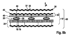
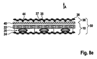
一実施態様において、エンベロープは、空洞を第一のサブ空洞と第二のサブ空洞に隔てる中間層を包含してよい。当該中間層は、流体密封の材料で作られていてよく、エンベロープの材料と共に溶接される際に流体密封シールの形成を支持するように構成されてよい。ガス発生剤は、中間層の片面又は両面に適用してよい。 In one embodiment, the envelope may include an intermediate layer separating the cavity into a first subcavity and a second subcavity. The intermediate layer may be made of a fluid tight material and may be configured to support the formation of a fluid tight seal when welded with the envelope material. The gas generating agent may be applied to one side or both sides of the intermediate layer.
さらなる実施態様において、エンベロープ構造を設けてよく、当該エンベロープ構造は共に接着された少なくとも2つのエンベロープによって形成されている。当該エンベロープ構造は、ガス発生剤が活性化される際に、第一の層と第二の層との間の距離の増加を可能にする。これは特に、エンベロープがその側部端で共に接着されている構成に有効である。積層構造の断熱容量の増加は、このようなエンベロープ構造を提供することにより、非常に効果的に向上させることができる。活性化の後に断熱容量の望ましい増加を達成するために、代わりに、積層構造の表面積をより少なくカバーするエンベロープを用いることができる。それによって、積層構造の通気性を効果的に増すことができる。 In a further embodiment, an envelope structure may be provided, the envelope structure being formed by at least two envelopes bonded together. The envelope structure allows an increase in the distance between the first layer and the second layer when the gas generant is activated. This is particularly useful in configurations where the envelope is bonded together at its side edges. The increase in the heat insulating capacity of the laminated structure can be improved very effectively by providing such an envelope structure. To achieve the desired increase in thermal insulation capacity after activation, an envelope that covers less surface area of the laminated structure can be used instead. Thereby, the air permeability of the laminated structure can be effectively increased.
積層構造は、複数の空洞を含んでいてよく、空洞のそれぞれは個別のエンベロープにより包まれていてよい。好ましくは、エンベロープのそれぞれは流体密封である。当該配置において、エンベロープはお互いに隣り合わせに、かつお互いに距離をとって、配置されることとなる。 The laminated structure may include a plurality of cavities, each of which may be enclosed by a separate envelope. Preferably each of the envelopes is fluid tight. In this arrangement, the envelopes are arranged next to each other and at a distance from each other.
このような配置は、特にエンベロープそれ自体が水蒸気透過性でない場合に、積層構造の通気性を提供する。むしろ、通気性はエンベロープ間のスペースにより維持される。当該スペースは、少なくとも積層構造の活性化されていない状態において形成される。活性化された状態において、エンベロープ間のスペースは、好ましくはあまり収縮しない。なぜなら、エンベロープは膨張するのみで、実質的にそれらの表面積を増加させないためである。それ故に、積層構造の活性化された状態においてもまた、通気性が維持される。 Such an arrangement provides the breathability of the laminated structure, especially when the envelope itself is not water vapor permeable. Rather, breathability is maintained by the space between the envelopes. The space is formed at least in a state where the stacked structure is not activated. In the activated state, the space between the envelopes preferably does not shrink much. This is because the envelopes only expand and do not substantially increase their surface area. Therefore, air permeability is also maintained in the activated state of the laminated structure.
エンベロープは、パッド又はチップの形状であってよく、このパッド又はチップは、活性化されていない状態においては扁平であり、活性化された状態において、膨張ピローの形状へ、形状を変化させる。 The envelope may be in the form of a pad or tip, which is flat in the unactivated state and changes shape to the shape of the expanded pillow in the activated state.
本明細書中で用いられる通気性は、積層構造、又はこのような積層構造を包含する布帛若しくは衣料の、積層構造の一方の面から他方の面へ水蒸気を運ぶことができるという特徴を特定するものと理解される。一つの実施態様において、積層構造はまた、少なくとも1つの水密かつ水蒸気透過性(通気性)の機能性層を含んでいるという点で、水密であってよい。一つの実施態様において、第一の層及び/又は第二の層は、前記機能性層を含む。別の実施態様において、前記機能性層は積層構造の追加の層を形成する。機能性層は、適切な膜、例えば延伸ポリテトラフルオロエチレン(PTFE)から作られている細孔性膜を用いて実現することができる。 Breathability as used herein identifies the feature of a laminated structure, or a fabric or garment that includes such a laminated structure, that can carry water vapor from one side of the laminated structure to the other. Understood. In one embodiment, the laminate structure may also be watertight in that it includes at least one watertight and water vapor permeable (breathable) functional layer. In one embodiment, the first layer and / or the second layer includes the functional layer. In another embodiment, the functional layer forms an additional layer of a laminated structure. The functional layer can be realized using a suitable membrane, for example a porous membrane made from expanded polytetrafluoroethylene (PTFE).
本明細書中で用いられる「水蒸気透過性層」という用語は、層又は前記積層構造若しくは層状複合体を通り抜ける水蒸気透過を確保する任意の層を包含すると意図される。この層は、本明細書中に記載の布地層又は機能性層であり得る。機能性層は、30(m2Pa)/Wよりも小さい水蒸気透過抵抗性(Ret)として測定される水蒸気透過性を有してよい。 The term “water vapor permeable layer” as used herein is intended to encompass any layer that ensures water vapor transmission through the layer or the laminated structure or layered composite. This layer can be a fabric layer or a functional layer as described herein. The functional layer may have a water vapor permeability measured as a water vapor transmission resistance (Ret) of less than 30 (m 2 Pa) / W.
水蒸気透過抵抗性又は抵抗性-蒸発-透過(resistance-evaporation-transmission)(Ret)は、一定の分圧勾配下で、所与の領域を通り抜ける蒸発潜熱流束を決定する、シート状構造又は複合体の固有の材料性質である。本発明に係る積層構造、布帛複合体、布地層又は機能性層は、水蒸気透過抵抗性Retが150(m2Pa)/Wよりも低い場合、水蒸気透過性であると見なされる。この機能性層は、好ましくは、30(m2Pa)/Wより低いRetを有する。水蒸気透過性はISO EN 11092(1993)に従い測定される。 Water vapor transmission resistance or resistance-evaporation-transmission (Ret) is a sheet-like structure or composite that determines the latent heat of vaporization through a given region under a constant partial pressure gradient. It is an intrinsic material property of the body. A laminated structure, fabric composite, fabric layer or functional layer according to the present invention is considered water vapor permeable when the water vapor transmission resistance Ret is lower than 150 (m 2 Pa) / W. This functional layer preferably has a Ret lower than 30 (m 2 Pa) / W. Water vapor permeability is measured according to ISO EN 11092 (1993).
本明細書中で用いられる「機能性層」という用語は、空気浸透及び/又はさまざまな他のガスの浸透、例えばガス化学的負荷、に対するバリアを提供するフィルム、膜又はコーティングを定義する。それ故に、この機能性層は空気不透過性及び/又はガス不透過性である。この機能性層は、具体的な実施態様においては空気不透過性であるが、他の用途においては空気透過性であり得る。 The term “functional layer” as used herein defines a film, membrane or coating that provides a barrier to air penetration and / or various other gas penetrations, such as gas chemical loading. This functional layer is therefore air impermeable and / or gas impermeable. This functional layer is air impermeable in specific embodiments, but may be air permeable in other applications.
さらなる実施態様において、この機能性層はまた、液体の水の浸透、及び理想的にはさまざまな液体の化学的負荷、に対するバリアを提供する。この層は、少なくとも0.13barの圧力で、液体の水の浸透を妨げる場合に、液体不透過性と見なされる。この水の浸透圧力は、機能性層のサンプルについて、ISO 811(1981)に関して記載された条件と同じ条件に基づいて測定してよい。 In further embodiments, this functional layer also provides a barrier to liquid water penetration and ideally various liquid chemical loads. This layer is considered liquid impervious if it prevents liquid water penetration at a pressure of at least 0.13 bar. This osmotic pressure of water may be measured based on the same conditions as described for ISO 811 (1981) for samples of functional layers.
機能性層は、一つの実施態様において、1又は複数の層を含んでよく、ここでこの機能性層は水蒸気透過性かつ空気-不透過性であって、空気不透過性でありながら水蒸気透過性(通気性)という特徴を提供する。好ましくはこの膜はまた、液体不透過性であり、少なくとも水不透過性である。 The functional layer, in one embodiment, may comprise one or more layers, wherein the functional layer is water vapor permeable and air-impermeable and is air impermeable while being water vapor permeable. Provides the characteristic of breathability. Preferably the membrane is also liquid impermeable and at least water impermeable.
本明細書中で用いるのに適切な水不透過性かつ水蒸気透過性の可撓性の膜が、多孔質延伸ポリテトラフルオロエチレン(PTFE)材料を開示する米国特許第3,953,566号明細書に開示されている。延伸多孔質PTFEは、フィブリルにより相互結合されたノードを特徴とする微細構造を有する。必要に応じて、米国特許第6,261,678号明細書に記載されているように、延伸PTFEを疎水性及び/又は疎油性コーティング材料でコーティングすることによって水不透過性を向上させてもよい。 A water impermeable and water vapor permeable flexible membrane suitable for use herein is disclosed in U.S. Pat.No. 3,953,566 which discloses a porous expanded polytetrafluoroethylene (PTFE) material. ing. Expanded porous PTFE has a microstructure characterized by nodes interconnected by fibrils. If desired, water impermeability may be improved by coating expanded PTFE with a hydrophobic and / or oleophobic coating material as described in US Pat. No. 6,261,678.
この水不透過性かつ水蒸気透過性の膜はまた、高分子量細孔性ポリエチレン若しくはポリプロピレン、細孔性ポリウレタン若しくはポリエステルなどの細孔性材料、又はポリエーテルポリウレタンなどの親水性モノリシックポリマーである可能性がある。 This water impermeable and water vapor permeable membrane may also be a porous material such as high molecular weight porous polyethylene or polypropylene, porous polyurethane or polyester, or a hydrophilic monolithic polymer such as polyether polyurethane. There is.
特定の実施態様において、積層構造及び/又はエンベロープは、可逆的に変化するように構成されていてよい。当該実施態様において、ガス発生剤は、分解又は蒸発し、そして個別の温度変化に応答して再結合又は再凝縮するように構成されている。活性化サイクルにおいて、温度の上昇に応答して、第一の層と第二の層との間の距離が、(ガス発生剤の活性化されていない構成における)第一の距離から、(ガス発生剤の活性化された構成における)第二の距離へ増加することとなる。不活性化サイクルにおいて、温度の低下に応答して、第一の層と第二の層との間の距離が、(ガス発生剤の活性化された構成における)第二の距離から、(ガス発生剤の活性化されていない構成における)第一の距離へ減少することとなる。このような一連の活性化サイクルプラス不活性化サイクルは、何度も繰り返してよい。 In certain embodiments, the laminated structure and / or envelope may be configured to reversibly change. In such embodiments, the gas generant is configured to decompose or evaporate and recombine or recondense in response to individual temperature changes. In the activation cycle, in response to an increase in temperature, the distance between the first layer and the second layer is from the first distance (in the non-activated configuration of the gas generant) (from the gas Will increase to a second distance (in the activated configuration of the generator). In the deactivation cycle, in response to a decrease in temperature, the distance between the first layer and the second layer is from the second distance (in the activated configuration of the gas generant) (from the gas Will decrease to a first distance (in an unactivated configuration of the generator). Such a series of activation cycles plus inactivation cycles may be repeated many times.
エンベロープは、活性化の後破裂しないと意図されている。そのため活性化プロセスは原則として可逆的であり、何度も繰り返されてよい。これは、原則として可逆的であるガス発生プロセスを必要とし、そして、放出されたガス状生成物が空洞内部にとどまる(すなわち、このエンベロープは、少なくとも一時的に、放出されたガスについてガス気密でなければならない)ガス発生プロセスを必要とする。可逆的ガス発生プロセスの典型的な例としては、(純粋化合物の形又は混合物の形の)ガス発生剤の物理的相転移、又は昇華プロセス(例えばヨウ素(jodine)の昇華)がある。可逆的ガス発生プロセスの別の例としては、例えば塩化アンモニウムの、可逆的分解がある。 The envelope is intended not to rupture after activation. The activation process is therefore reversible in principle and can be repeated many times. This requires a gas generation process that is reversible in principle, and the released gaseous product remains inside the cavity (i.e. this envelope is at least temporarily gas-tight for the released gas). Requires a gas generation process. Typical examples of reversible gas generation processes are physical phase transitions of gas generants (in the form of pure compounds or mixtures), or sublimation processes (eg, sublimation of iodine). Another example of a reversible gas generation process is the reversible decomposition of, for example, ammonium chloride.
好ましくは、積層構造及び/又はエンベロープは可撓性であり、「自己回復能力」を有する。それによって、不活性化サイクルにおいて、エンベロープはその元の形状、すなわちガス発生剤の活性化が開始する前のその形状に、自動的に戻る。このプロセスを支持するためのさらなる機械的作用は必要ない。エンベロープの「自己回復能力」は、エンベロープの流体密封性によって支持される。すなわち、不活性化サイクルにおいて、ガス発生剤は一般に、気相から液相へ変換される際に、その密度を増加させることとなる。それ故に、ガス発生剤は活性化されていない構成において、活性化された構成における体積よりもはるかに小さい体積を占めることとなる。不活性化サイクルの間にエンベロープ内に流れ込む空気がない条件では、ガス発生剤の変換は、エンベロープが最小体積の空洞を囲む(扁平な)形状へ、エンベロープの収縮を引き起こすこととなる。このようなプロセスによってまた、第一の層と第二の層との間の距離が、ガス発生剤の活性化されていない構成における元の距離に戻ることとなる。 Preferably, the laminated structure and / or envelope is flexible and has “self-healing ability”. Thereby, in the deactivation cycle, the envelope automatically returns to its original shape, i.e. its shape prior to the start of activation of the gas generant. No further mechanical action is required to support this process. The “self-healing ability” of the envelope is supported by the fluid tightness of the envelope. That is, in the deactivation cycle, the gas generant generally increases its density as it is converted from the gas phase to the liquid phase. Therefore, the gas generant will occupy a much smaller volume in the non-activated configuration than in the activated configuration. In the absence of air flowing into the envelope during the deactivation cycle, the conversion of the gas generant will cause the envelope to contract into a (flat) shape that encloses the cavity with the smallest volume. Such a process also causes the distance between the first layer and the second layer to return to the original distance in the non-activated configuration of the gas generant.
積層構造の構成は、上記の概略のように、個別のエンベロープにより囲まれる巨視的空洞の供給を可能にし、熱に供されると活性化することができる。当該エンベロープは、「ピロー」又は「ポケット」の形状をとっていてよい。このエンベロープは、ガス発生剤の活性化されていない構成において、1mm以上の横寸法を有していてよい。具体的な実施態様においては、エンベロープは5mm以上の、好ましくは15mm以上の横寸法を有していてよい。典型的には、エンベロープは1mmよりも小さい厚さ寸法を有していてよい。この文脈で用いられる横寸法は、幅/長さ平面、すなわち厚さ方向に直交する平面におけるエンベロープの最も小さい寸法を意味し、これは一般に、ガス発生剤の活性化されていない構成において、エンベロープの群を抜いて最も小さい寸法である。それ故に、横寸法は基本的に、ガス発生剤の活性化された構成においてエンベロープが到達することができる、厚さの最大増加を規定する。複数の当該扁平エンベロープは、積層構造の高い通気性と、それ故に着用者にとってより高い快適さのレベルを可能にする、(上記の)扁平積層構造を形成するために用いてよい。 The configuration of the laminated structure allows for the provision of macroscopic cavities surrounded by individual envelopes, as outlined above, and can be activated when subjected to heat. The envelope may take the form of a “pillow” or “pocket”. The envelope may have a lateral dimension of 1 mm or more in an unactivated configuration of the gas generant. In a specific embodiment, the envelope may have a lateral dimension of 5 mm or more, preferably 15 mm or more. Typically, the envelope may have a thickness dimension that is less than 1 mm. The lateral dimension used in this context means the smallest dimension of the envelope in the width / length plane, i.e. the plane orthogonal to the thickness direction, which generally means that in an unactivated configuration of the gas generant, This is the smallest dimension. Therefore, the lateral dimension basically defines the maximum increase in thickness that the envelope can reach in the activated configuration of the gas generant. A plurality of such flat envelopes may be used to form a flat laminated structure (as described above) that allows for a high breathability of the laminated structure and hence a higher level of comfort for the wearer.
体積増加を用いて表すと、空洞は、ガス発生剤の活性化された構成において、ガス発生剤の活性化されていない構成における体積に対して10〜1000の体積増加を有してよい。好ましくはこの体積増加は40より大きくてよい。 Expressed using volume increase, the cavity may have a volume increase of 10-1000 in the activated configuration of the gas generant relative to the volume in the non-activated configuration of the gas generant. Preferably this volume increase may be greater than 40.
なおさらなる実施態様において、空洞を囲んでいるエンベロープは外側のエンベロープ及び内側のエンベロープを含んでよく、この外側のエンベロープは外側の空洞を囲み、この内側のエンベロープは外側の空洞内に位置付けられてこの空洞を囲んでいる。 In yet a further embodiment, the envelope surrounding the cavity may include an outer envelope and an inner envelope, the outer envelope surrounding the outer cavity, the inner envelope positioned within the outer cavity and Surrounds the cavity.
上記の積層構造を、布帛複合構造に組み入れてよい。「布帛」という用語は、糸、繊維、又はフィラメントを織り合わせることにより製造された平面布地構造を意味する。この布地構造は、織物、不織物、フリース又はそれらの組み合わせであってよい。「不織」布地層は、繊維及び/又はフィラメント、フェルト、編物、繊維バットなどのネットワークを含む。「織」布地層は、平織、千鳥綾織、バスケット織、朱子織、綾織などの任意の布帛の織り方を用いている織布帛である。平織及び綾織は、この業界で用いられている最も一般的な織り方だと考えられている。 The above laminated structure may be incorporated into a fabric composite structure. The term “fabric” means a flat fabric structure made by weaving yarns, fibers or filaments. This fabric structure may be woven, non-woven, fleece or combinations thereof. “Nonwoven” fabric layers include fibers and / or networks of filaments, felts, knitted fabrics, fiber batts and the like. The “woven” fabric layer is a woven fabric that uses any weaving method such as plain weave, zigzag twill, basket weave, satin weave and twill weave. Plain weave and twill are considered the most common weaving methods used in this industry.
当該布帛複合構造は、典型的にはお互いに配置された複数の布帛層を含むこととなる。この複数の布帛層は、外側及び内側を有する外側の防熱殻構造を包含してよい。この複数の布帛層はまた、適応可能な断熱を提供する、上記の積層構造を包含してよい。 The fabric composite structure will typically include a plurality of fabric layers disposed on each other. The plurality of fabric layers may include an outer thermal shell structure having an outer side and an inner side. The plurality of fabric layers may also include a laminate structure as described above that provides adaptable insulation.
特定の実施態様において、適応可能な断熱を提供する積層構造は、外側の防熱殻構造の内側上に配置されてよい。 In certain embodiments, a laminated structure that provides adaptive heat insulation may be disposed on the inside of the outer thermal barrier structure.
一つの実施態様として、外側の防熱殻構造は、初期の防炎を提供する物品(例えば衣料など)の外層を意味する。この外側の防熱殻構造は、耐炎性で熱的に安定した布地を含んでよく、例えば、ポリイミド(メタ-アラミド、パラ-アラミド)又はそれらのブレンドなどの耐炎性布地を含む、織布地、編物又は不織布地がある。耐炎性又は熱的に安定した布地の具体例には、ポリベンズイミダゾール(PBI)繊維;ポリベンゾオキサゾール(PBO)繊維;ポリジイミダゾピリジニレンジヒドロキシフェニレン(PIPD);モダクリル繊維;E.I. DuPont de Nemours, Incによりノーメックス(Nomex)(登録商標)の商品名で販売されているポリ(メタフェニレンイソフタルアミド);E.I. DuPont de Nemours, Inc.によりケブラー(Kevlar)(登録商標)の商品名で販売されているポリ(パラフェニレンテレフタルアミド);メラミン;難燃性(FR)綿;FRレーヨン、PAN(ポリアクリロニトリル(acrylnitryl))がある。前述の繊維を2つ以上含む布帛もまた利用してよい(例えばノーメックス(Nomex)(登録商標)/ケブラー(Kevlar)(登録商標))。一つの実施態様において、織ノーメックス(Nomex)(登録商標)Delta T(200g/m2の布地重量)で作られた外殻層が用いられる。 In one embodiment, the outer thermal barrier structure refers to the outer layer of an article (eg, clothing) that provides initial flame protection. This outer thermal barrier structure may comprise a flame resistant and thermally stable fabric, for example a woven fabric comprising a flame resistant fabric such as polyimide (meta-aramid, para-aramid) or blends thereof, There are knitted or non-woven fabrics. Specific examples of flame resistant or thermally stable fabrics include polybenzimidazole (PBI) fiber; polybenzoxazole (PBO) fiber; polydiimidazopyridinylene dihydroxyphenylene (PIPD); modacrylic fiber; EI DuPont de Nemours, Poly (metaphenylene isophthalamide) sold under the trade name Nomex® by Inc .; sold under the trade name Kevlar® by EI DuPont de Nemours, Inc. Poly (paraphenylene terephthalamide); melamine; flame retardant (FR) cotton; FR rayon, PAN (polyacrylonitrile). Fabrics containing two or more of the aforementioned fibers may also be utilized (eg Nomex® / Kevlar®). In one embodiment, an outer shell layer made of woven Nomex® Delta T (200 g / m 2 fabric weight) is used.
耐炎性材料は、国際標準EN ISO 15025(2003)で規定される。DIN EN ISO 14116(2008)は、材料の耐炎性を評価するための試験方法を規定する。DIN EN ISO 14116(2008)に従って、様々なレベルの耐炎性が規定されている。例として、消防士の衣料用に用いられるべき耐炎性材料は、DIN EN ISO 14116(2008)のレベル3について規定された試験手順に合格することが求められる。他の用途については、レベル1及び2について規定される、より厳しくない選択基準で十分である場合がある。 Flame resistant materials are defined in the international standard EN ISO 15025 (2003). DIN EN ISO 14116 (2008) specifies test methods for evaluating the flame resistance of materials. Various levels of flame resistance are defined according to DIN EN ISO 14116 (2008). As an example, a flame resistant material to be used for firefighter clothing is required to pass the test procedures specified for Level 3 of DIN EN ISO 14116 (2008). For other applications, the less stringent selection criteria specified for levels 1 and 2 may be sufficient.
布帛はまた、バリア構造を含んでよい。一つの実施態様において、このバリア構造は、外側の防熱殻構造の内側上に配置されることとなる。 The fabric may also include a barrier structure. In one embodiment, the barrier structure will be placed on the inside of the outer thermal barrier structure.
具体的な用途において、バリア構造は少なくとも1つの機能性層を含む。前記機能性層は、水蒸気透過性かつ防水性であってよく、少なくとも1つの水蒸気透過性かつ防水性の膜を含む。 In a specific application, the barrier structure includes at least one functional layer. The functional layer may be water vapor permeable and waterproof and includes at least one water vapor permeable and waterproof membrane.
バリア構造は、液体バリアとしての役割を果たす構成要素であるが、水蒸気はこのバリアを通過することができる。例えば消防士の出動用具一式などの衣料において、当該バリア構造は水が衣料の内部に入らないようにし、そしてそれによって消防士が運ぶ重量を最小限にする。加えて、このバリア構造は水蒸気(汗)を逃がすことができる-これは、高温環境で作業をする際に重要な機能である。典型的には、このバリア構造は、不織布帛又は織布帛などの、少なくとも1つの布地層に積層された膜を含む。少なくとも1つの布地層(積層という用語の下でも知られる)に積層させるために用いられる膜材料には、延伸ポリテトラフルオロエチレン(PTFE)、ポリウレタン及びそれらの組み合わせがある。当該積層の市販されている例としては、クロステック(CROSSTECH)(登録商標)モイスチャーバリアラミネーツ(moisture barrier laminates)又はネオプレン(Neoprene)(登録商標)メンブレン(membrane)の名前で市販の、不織若しくは織メタ-アラミド布帛上の積層がある。 The barrier structure is a component that acts as a liquid barrier, but water vapor can pass through this barrier. In apparel, such as a firefighter outfit, for example, the barrier structure prevents water from entering the apparel and thereby minimizes the weight carried by the firefighter. In addition, this barrier structure can release water vapor (sweat) —this is an important function when working in high temperature environments. Typically, the barrier structure includes a film laminated to at least one fabric layer, such as a nonwoven or woven fabric. Membrane materials used to laminate to at least one fabric layer (also known under the term laminate) include expanded polytetrafluoroethylene (PTFE), polyurethane and combinations thereof. Commercially available examples of such laminates include non-woven, commercially available under the name CROSSTECH® moisture barrier laminates or Neoprene® membrane. Or there is a laminate on a woven meta-aramid fabric.
一つの実施態様において、欧州特許第0 689 500(B1)号明細書に記載されているように作られている延伸PTFE(ePTFE)の膜を含むバリア構造が用いられる。このバリア層は、布地重量が90g/m2の、不織アラミド布地(15%パラ-アラミド及び85%メタ-アラミド)で作られている布地層に接着していてよい。このようなバリア構造は、ゴアテックス(GORE-TEX)(登録商標)ファイアーブロッカー(Fireblocker) Nという名で市販されている。別の実施態様において、クロステック(CROSSTECH)(登録商標)/ノーメックス(Nomex)(登録商標)モイスチャーバリア(moisture barrier)という名で市販のバリア構造が用いられる。当該湿気バリアは、布地重量が105g/m2のポリアミド布地(ノーメックス(Nomex)(登録商標)IIIA)に付着したポリウレタン層を有するePTFEフィルムを含む。例えば米国特許第4 493 870号明細書、米国特許第4 187 390号明細書、又は米国特許第4 194 041号明細書に記載されている他のバリアを用いてもよい。 In one embodiment, a barrier structure is used that includes an expanded PTFE (ePTFE) membrane made as described in EP 0 689 500 (B1). This barrier layer may be adhered to a fabric layer made of nonwoven aramid fabrics (15% para-aramid and 85% meta-aramid) with a fabric weight of 90 g / m 2 . Such a barrier structure is commercially available under the name GORE-TEX® Fireblocker N. In another embodiment, a commercially available barrier structure under the name CROSSTECH® / Nomex® moisture barrier is used. The moisture barrier includes an ePTFE film having a polyurethane layer attached to a polyamide fabric (Nomex® IIIA) having a fabric weight of 105 g / m 2 . For example, other barriers described in US Pat. No. 4,493,870, US Pat. No. 4,187,390, or US Pat. No. 4,194,041 may be used.
湿気バリア以外のバリアが考えられる。これには例えば、気体、液体及び/若しくはエアロゾルの形状の化合物、若しくは気体、液体及び/若しくはエアロゾルの形状の生物材料を含む物質、のような、気体並びに/又は液体の透過を妨げる少なくとも1つの機能性層を提供するバリアがある。具体的な実施態様において、当該他のバリア層はまた、通気性であってよい。 Barriers other than moisture barriers are possible. This includes, for example, a gas, liquid and / or aerosol form compound, or a substance containing a biological material in the form of a gas, liquid and / or aerosol, at least one which prevents the permeation of the gas and / or liquid There is a barrier that provides a functional layer. In a specific embodiment, the other barrier layer may also be breathable.
バリア構造は、外側の防熱殻構造と、適応可能な断熱を提供する積層構造との間に位置してよい。 The barrier structure may be located between the outer thermal barrier structure and a laminated structure that provides adaptive thermal insulation.
この布帛は、環境の影響から着用者を保護することが必要とされる、又は所与の環境条件下で、望まれる機能特性を提供することが必要とされる、消火活動、警察、軍隊又は工業の作業などの用途に典型的に用いられる、防護服又は機能性衣料に用いてよい。この衣料は、熱、炎、又は液体による衝撃から着用者を保護することが必要とされる場合がある。典型的には、この衣料が、着用者に、彼が行うことになっている作業を彼がすることができるような十分な快適さを提供することが望まれている。 This fabric is required to protect the wearer from environmental influences or to provide the desired functional properties under given environmental conditions, fire fighting, police, military or It may be used in protective clothing or functional clothing typically used for applications such as industrial work. This garment may be required to protect the wearer from heat, flame, or liquid impact. Typically, it is desired that this garment provide the wearer with sufficient comfort that he can do the work he is supposed to do.
具体的には、布帛を防火服/防熱服における使用に適合させることが意図される。 In particular, it is intended to adapt the fabric for use in fire / heat proof clothing.
本発明の例となる実施態様は、実施態様を示す添付の図面を参照しながら、以下に、より詳細に記述される。 Exemplary embodiments of the present invention will be described in more detail below with reference to the accompanying drawings illustrating the embodiments.
同一であるか、又は対応する機能を有する個別の実施態様の構成要素は、全ての図においてそれぞれ同一の参照数字によって示される。以下の記載において、当該構成要素は、当該構成要素を含む実施態様のうち第一のものに関してのみ記載されている。同一の記載は、同一の構成要素が包含され、同一の参照数字によって示されている個別の後続の実施態様に当てはまると理解されるべきものである。何か反対に述べられていない限りは、一般に、個別の先の実施態様におけるその構成要素の対応する記載が参照される。 Components of separate embodiments that are identical or have corresponding functions are denoted by the same reference numerals in all figures. In the following description, the component is described only with respect to the first of the embodiments including the component. It should be understood that the same description applies to individual subsequent embodiments that include the same components and are denoted by the same reference numerals. Unless stated to the contrary, reference is generally made to the corresponding description of its components in the individual previous embodiments.
図1aは、一実施態様に係る層8の簡易概略断面図を示している。当該層8は、エンベロープを調製するのに用いてよい。層8は、被覆層8a、流体密封層8b及びシーリング層8cを含む積層である。一例において、アルミニウム/プラスチック複合材料で作られている層8は、ポリエチレンテレフタラート(PET)-被覆層8a、アルミニウム(Al)-流体密封層8b及びポリエチレン(PE)-シーリング層8cを含む。十分な流体密封性を提供する目的での、Al-層8bの合理的な厚さの範囲は4μm〜25μmである。示されている例において、Al-層8bは少なくとも12μmの厚さを有する。PE-層8cは、エンベロープを作り出す目的で、隣接する積層層8を流体密封的に共に接着することができるシーリング層として用いられる。PE-層8cの厚さは、20μm〜60μmが可能である。好ましい厚さは約40μmである。PET-層8aは、エンベロープの外表面の望ましい特徴を提供する被覆層として用いてよい。この例において、12μm厚のPET-層8aが用いられる。記載されている積層層8は、Kobusch-Sengewald GmbH社、Germanyによって入手してよい。
FIG. 1 a shows a simplified schematic cross-sectional view of a layer 8 according to one embodiment. The layer 8 may be used to prepare an envelope. The layer 8 is a laminate including a
エンベロープを形成するための代替の層8が図1bに示されている。この層8はまた、PEで作られている厚さ40μmの被覆層8a、厚さが少なくとも12μmのAl層8b、及び厚さ40μmのPEシーリング層8cを包含している積層である。この実施態様において、被覆層8aはシーリング層8cと同じ材料で作られている。被覆層8aは、追加のシーリング層として用いてよい。
An alternative layer 8 for forming the envelope is shown in FIG. 1b. This layer 8 is also a laminate comprising a 40 μm
図3aは、ガス発生剤(一般に18と指定されている)を包含する空洞16を囲んでいるエンベロープ(一般に20と指定されている)の簡易概略断面図を示している。図3aにおいて、及び図3b、3c、3d、4a、4b、4cのそれぞれにおいて、エンベロープ20がガス発生剤18の活性化されていない構成において示されており、そしてそれ故にエンベロープ20は、非膨張の、本質的に扁平の形状をしており、また、活性化されていない状態と見なされる。図3a〜3d及び図4a〜4cに示される扁平の構成において、エンベロープ20は厚さ方向に直交する方向、すなわち横方向のエンベロープ20の寸法よりも著しく小さい厚さ方向の寸法を有する。厚さ方向のエンベロープ20の寸法は、図3a〜4cにおいて、dにより指定されている。横方向のエンベロープ20の寸法は、図3a〜4cにおいて、A0により指定されている。ここで、A0はエンベロープ20の溶接部の一方の端から、向かい側の溶接部の端までの長さを指定している。一般に「円形」又は四角形の形状のエンベロープを備える実施態様において、エンベロープの寸法A0は、全ての横方向について実質的に等しくてよい。一般に細長い形状を有するエンベロープの他の実施態様において、幅方向の寸法A0は、長さ方向の寸法A0よりも小さくてよい。
FIG. 3a shows a simplified schematic cross-sectional view of an envelope (generally designated 20) surrounding a
一実施態様において、エンベロープ20は2つのエンベロープ層12、14で作られている。エンベロープ層12、14はそれぞれ、図1a又は1bにおいて示されている層8のような構成を有してよい。特に、はっきりとは示されていないが、エンベロープ層12、14はそれぞれ、図1a又は図1bに描かれている層8に相当する3つの層より構成されてよい。エンベロープ層12は、エンベロープ20の上方の部分を形成しており、当該上方の部分は、空洞16の上方の部分を囲んでいる。エンベロープ層14は、エンベロープ20の下方の部分を形成しており、当該下方の部分は空洞16の下方の部分を囲んでいる。示されている実施態様において、エンベロープ層12及びエンベロープ層14は、同一の構成、例えば図1aに示されている層8の構成を有する。エンベロープ20は、最も内側のシーリング層、中間流体密封層、及び外側の被覆層を有する。
In one embodiment,
代わりに、エンベロープ20は、図1bに描かれている層8から構成される2つのエンベロープ層12、14より構成されていてよく、又は図1aに描かれている層8から構成される1つのエンベロープ層12及び図1bに描かれている層8から構成される1つのエンベロープ層14より構成されていてよい。材料それ自体が流体密封であり、かつ流体密封エンベロープ20が作られるように流体密封的に共に接着されていることを前提として、代替の材料を、具体的には単層又は多かれ少なかれ複雑な構成の積層層を、上記の概略のように、エンベロープ20を作るために用いてよい。一つの実施態様において、エンベロープ層は流体密封の単一の層(単層)で作られていてよい。前記層は、溶接又は接着によってエンベロープに形成させ得る。
Alternatively, the
エンベロープ20は、ガス発生剤18が充填されている空洞16を囲む。ガス発生剤18は、室温で適切な平衡蒸気圧を有する液体となるよう選択される。室温は、ガス発生剤18の活性化されていない構成を定義するものと考えられる。図3aに示されるガス発生剤18の活性化されていない構成において、ガス発生剤18は実質的に、その液相状態にあり、18'により指定される。エンベロープ20は、空洞16の、実質的に流体密封の囲いを提供し、そしてそれ故に空洞16は十分な量のガス発生剤18を含有し、そして空洞16の残りの体積は、ガスで、具体的にはガス発生剤18が充填された時点で空洞16内に囲まれていた残りの量の空気又は他のガスで、満たされている。開示の例においては、ガス発生剤18は化学式CF3CF2C(O)CF(CF3)2を有する流体である。当該流体は、典型的には消火のために用いられ、3Mより「ノベック(NOVEC)(登録商標)1230 消火薬剤(Fire extinguishing fluid)」という商品名で市販されている。上記に示したように、他の流体をガス発生剤のために用いてよい。
The
図3aに示されるエンベロープ20を製造する第一の方法は以下の通りである。
A first method for manufacturing the
第一のシーリングステップ:
図1a又は1bに係る材料から作られている2つのエンベロープ層12、14を、それらそれぞれのシーリング層がお互いに面するように、お互いに重ね合わせる。四角形のエンベロープ20を形成するために、シーリング層を接触させてシーリング層を共に溶接するように、ホットバー(hot bar)(シーリング幅:2mm)をエンベロープ層12、14に接触させる。この手順は、四角形のエンベロープ20の4つの辺のうち、3つについて行う。このようにして、一辺が開口したエンベロープ20を形成する。
First sealing step:
Two envelope layers 12, 14 made of the material according to FIG. 1a or 1b are superposed on each other such that their respective sealing layers face each other. In order to form the
充填ステップ:
エンベロープ20を精密天秤の上に置き、ガス発生剤18をエンベロープ内部に、例えば注射針を使って充填する。充填されることになっているガス発生剤の量は、天秤により制御する。
Filling step:
The
一例としては、エンベロープ20が以下の仕様である場合は、0.07gの量のガス発生剤18をエンベロープ20内部に充填することとなる。すなわち、エンベロープ20は上記の通り、PET/Al/PEより構成される2つのエンベロープ層12、14から形成する。エンベロープ20の外側のサイズは20mm長及び20mm幅であり(16mm長及び16mm幅という空洞の内側のサイズに対応する)、ガス発生剤18はノベック(NOVEC)(登録商標)1230を選択する。
As an example, when the
第二のシーリングステップ:
充填ステップの終了後、エンベロープ20の開口した辺を、第四の2mmシーリングラインによって閉じる。次にエンベロープ20をシーリングラインに沿って精密に切る。
Second sealing step:
After completion of the filling step, the open side of the
上記の概略のように作成されるエンベロープに対する充填量の正確さは、以下の通り測定することができる。 The accuracy of the filling amount for the envelope created as outlined above can be measured as follows.
所定の量のエンベロープ20(例えば10エンベロープ)を第一のシーリングステップに従い作成し、これらのエンベロープ20のそれぞれにしるしをつけ、それぞれ4つのデジタル(digit)天秤(例えばSatorius BP121S)で秤量する。液体の形状のガス発生剤18の所定の量を、時間駆動バルブを包含する重力供給リザーバーから出ているパイプを通し、注射針を通してエンベロープの内部に注入する。所定のバルブ開口時間は、調節可能な電子タイマーにより保証されている。各エンベロープ20を第二のシーリングステップによって直ちに閉じる。充填されたエンベロープ20のそれぞれの重さを測定し、(充填前に測定された)空のエンベロープ20の重量を差し引く。偏差を最大で、サンプルセットの平均値からプラス/マイナス10%にできるようにすべきである。
A predetermined amount of envelope 20 (eg, 10 envelopes) is created according to a first sealing step, each of these
図3aに係るエンベロープ20を製造する第二の方法は、図2a〜2dに示されており、以下の通りである。
A second method of manufacturing the
第一のステップ(図2a):
図1aに係る積層材料8から作られている細長いシート、例えば65mm幅及び1.3m長のシートを用いる。代わりに、異なるサイズ及び/又は別の積層材料から作られているシート、例えば図1bに示される積層材料8から作られているシートを用いてもよい。このシートを、積層8の被覆層8a(図1a又は図1b参照)を外側に位置付け、シーリング層8cを内側に位置付けるような形で、その長辺に沿って折る。それによって、上方のエンベロープ層12及び下方のエンベロープ層14が、エンベロープ層12、14のシーリング層がお互いに向かい合っているような形で形成される。このようにして、プレ-エンベロープ101を作り出す。プレ-エンベロープ101は、32.5mmの幅及び1.3mの長さを有する。プレ-エンベロープ101は、その一方の長辺102で閉じており、その向かい側の長辺103に沿って開口している。プレ-エンベロープ101の短辺104及び105は両方とも開口している。
First step (Fig. 2a):
An elongate sheet made from the laminate material 8 according to FIG. 1a is used, for example a sheet 65 mm wide and 1.3 m long. Alternatively, sheets made from different sizes and / or different laminate materials may be used, for example sheets made from the laminate material 8 shown in FIG. 1b. This sheet is folded along its long side so that the
第二のステップ(図2b):
エンベロープ層12、14の2つのシーリング層をお互いに接触させるように、回転超音波溶接ホイール(例えば5mm幅)をプレ-エンベロープ101の開口長辺103に接触させる。このシーリング層を、プレ-エンベロープ101の開口長辺103に平行に延在するシーリングライン106に沿って連続的に共に溶接する。その結果、長辺103は閉じ、プレ-エンベロープ101は2つの開口短辺104、105を備える管状の形となる。シーリング層をお互いに接触させるように、ホットシーリングバー(hot sealing bar)(シーリング幅:2mm)を、プレ-エンベロープ101の、より短い辺の1つである105に接触させる。プレ-エンベロープ101をより短い辺105で閉じるように、このシーリング層を、より短い辺105に平行に延在するシーリングライン107に沿って共に溶接する。その結果プレ-エンベロープ101は一方の端が閉じた管の形状となる。
Second step (Figure 2b):
A rotating ultrasonic welding wheel (eg 5 mm wide) is brought into contact with the open
次に、開口短辺104を閉じた短辺105よりも高く保持し、開口短辺104を通してガス発生剤18を開口管状プレ-エンベロープ101の中に充填する。例として、内側のサイズが23mm幅及び1m長の空洞を形成している、記載のプレ-エンベロープ101(このプレ-エンベロープ101は、上記のようにかつ図1aに示されるように、PET/Al/PEより構成される積層層8で作られている)について、及び上記のようにノベック(NOVEC)(登録商標)1230として既知の液体であるガス発生剤18について、4mlの量のガス発生剤18をプレ-エンベロープ101の中に充填する。
Next, the opening
第三のステップ(図2c)
空洞内に充填されたガス発生剤18が、プレ-エンベロープ101の、閉じたより短い辺105に集まるように、プレ-エンベロープ101を、その開口短辺104を上に向けて保持し、直立した位置で保持する。閉じたより短い辺105から開始して、プレ-エンベロープ101を第二の回転超音波溶接ホイール110に密接に接触させる。溶接ホイール110は、一組の溶接ホイール110、111を備える超音波溶接機械の一部である。溶接ホイール110は、複数の周縁のシール輪郭114A、114B、…を備えて形成されている周縁の面112を有する。シール輪郭114A、114B、…のそれぞれは、作られることになっているエンベロープ20A、20B、…(図2d)のシーリングラインの形状に対応する形状を有する。この構成において、溶接ホイール111は平面の周縁表面を有する。
Third step (Fig. 2c)
The pre-envelope 101 is held in an upright position with the
プレ-エンベロープ101は、その閉じた短辺105から開始して、一組の溶接ホイール110、111を通して運ばれる。プレ-エンベロープ101の進行方向を示している図2cの矢印Bを参照のこと。このようにして、溶接ホイール110は最初にプレ-エンベロープ101の閉じた短辺105に接触し、そして最終的にプレ-エンベロープ101の開口短辺104に接触する。
The pre-envelope 101 is carried through a set of
溶接ホイール110がプレ-エンベロープ101に接触する際、ガス発生剤18は、シーリング輪郭114A、114Bのうち1つがプレ-エンベロープ101に接触する領域において、回転超音波溶接ホイール110、111によって押しのけられる。なぜなら、このような領域において、このシーリング層はお互いに接触させられて、共に溶接されるためである。このようにして、最終のエンベロープ20A(図2d)のシーリング部位を画定している閉じたシーリング輪郭116Aが、プレ-エンベロープ101に形成される。
When the
回転溶接ホイール110、111の間の間隙を通ってプレ-エンベロープ101が動く時に、複数の連続したシーリング輪郭116A、116B、…がプレ-エンベロープ101に形成される。各シーリング輪郭116A、116B、…は、所定の量のガス発生剤18で充填された個別の空洞16A、16B、…を囲む。
As the pre-envelope 101 moves through the gap between the
上記の手順に従って、プレ-エンベロープ101に形成された各空洞16A、16B、…をおよそ同じ所定量のガス発生剤18で充填することができるということが分かってきた。例えば一組の超音波溶接ホイール110、111の形状をした、超音波溶接ツールを用いることで、特に良好な再現性のある結果を得て、シーリング輪郭116A、116B、…をプレ-エンベロープ101に作成することができる。
It has been found that according to the above procedure, each
上記に概説されている寸法を有する一例において、それぞれ20mm幅及び23mm長の外側の寸法並びに16mm幅及び18mm長の空洞サイズを有する、40の充填されたシーリング輪郭116A、116B、…を作り出すことができる。
In one example having the dimensions outlined above, creating 40 filled sealing
第四のステップ(図2d):
最終的に、シーリング輪郭116A、116B、…が形成されている最終のプレ-エンベロープ101を、例えばシーリング輪郭116A、116B、…の外側の寸法の形状を有する抜型(cutting dye)を備える手動の又は自動の標準のダイカット(dye cut)機を用いて、切り取る。このようにして、図2dに示される個別のエンベロープ20A、20B、…が作成される。
Fourth step (Fig. 2d):
Finally, the
第四のステップ、すなわち最後の切り取りステップを省くこともまた考えられる。その結果、複数の単一エンベロープ20の代わりに、複数のエンベロープ20A、20B、20C、…の配列を包含するサンドイッチ型の積層シート100(図2e参照)、200(図2f参照)が提供される。このようなシート層構造100、200において、エンベロープ20A、20B、20C、…は、図2a〜2cに係るプレ-エンベロープ101から作成される、図2eのシート層構造100について示されているように、単一のラインに沿って並んでいてよい。長方形の又は四角形の形状の平面プレ-エンベロープ201を用いること、及びエンベロープ20A1、20B1、20C1、…、20A2、20B2、20C2、…、20A3、20B3、20C3、…の複数のラインを包含するシート層構造200を作成すること、もまた可能であり、エンベロープの当該ラインは図2fに示されるように隣同士に配置され、お互いに平行に延在している。シート層構造100又はシート層構造200の、エンベロープの外側にある材料は、エンベロープ20A1、20B1、20C1、…、20A2、20B2、20C2、…、20A3、20B3、20B3、…について、接続構造109、209を形成する。
It is also conceivable to omit the fourth step, ie the last trimming step. As a result, sandwich-type laminated sheets 100 (see FIG. 2e) and 200 (see FIG. 2f) including an array of a plurality of
図2gに示されているさらなる実施態様において、隣接するエンベロープの間にエンベロープ層12、14を形成しているシート材料の、使われていない部位212を切り取ることによって、各エンベロープがシート材料12、14により形成される相互接続ウェブ219によってその隣接するエンベロープとなお接続している形で、エンベロープ20A1、20B1、20C1、…、20A2、20B2、20C2、…、20A3、20B3、20C3、…のメッシュ210を作成することができる。
In a further embodiment shown in FIG. 2g, each envelope is formed into a
上記第二の方法に従い作成されるエンベロープについての充填量の正確さは、以下の通り測定することができる。 The accuracy of the filling amount for the envelope produced according to the second method can be measured as follows.
所定の量のエンベロープ20(例えば10エンベロープ)を、上記の第一から第四のシーリング/充填ステップに従って作成し、これらのエンベロープ20のそれぞれにしるしをつけ、それぞれ4つのデジタル(digit)天秤(例えば Satorius BP121S)で秤量する。エンベロープ20のそれぞれをガス発生剤18の活性化温度(temperate)よりも十分高い温度のホットプレートの上に置き、確実にエンベロープ20のそれぞれが破裂して、ガス状のガス発生剤18を完全に放出することとなるようにする。空のエンベロープをそれぞれ4つのデジタル(digit)天秤で秤量する。各エンベロープの重量損失を計算する。エンベロープ材料が湿気を帯びる場合に備えて、このエンベロープは、少なくとも1時間、同じ環境、理想的には23℃で65%の相対湿度の環境で、調整しなければならない。
A predetermined amount of envelope 20 (e.g., 10 envelopes) is created according to the first through fourth sealing / filling steps described above, and each of these
エンベロープの流体密封性は、以下の方法のうちの1つに従って測定することができる。 The fluid tightness of the envelope can be measured according to one of the following methods.
エンベロープの流体密封性を測定するための方法1:
各エンベロープ20にそれぞれしるしをつける。各エンベロープ20を4つのデジタル(digit)天秤(例えばSatoriusBP121S)で秤量する。エンベロープ20を所定の環境条件(20℃、65%相対湿度)下で保存する。記載の秤量手順を、1か月の保存後に再度行う。この手順を少なくとも6か月間続ける。6か月後の重量損失は、充填重量の20%より少なく、より良くは10%よりも少なく、理想的には1%よりも少なくあるべきである。加えて、6か月後に、各エンベロープ20の機能性をホットプレート上又は水浴中で確認する。エンベロープ20は、活性化温度よりも高い温度に供された際に、厚さの増加を示さなければならない。
Method 1: to measure the fluid tightness of the envelope
Mark each
図3bは、さらなる実施態様に係る、空洞16を囲んでいるエンベロープ20を示している。図3bに示されるエンベロープ20は、注入補助物19に適用されたガス発生剤18を包含している。注入補助物19は、ガス発生剤18を吸収することのできる任意の材料、例えば、吸収性の紙材料、織布地材料若しくは不織布地材料、又はスポンジ様材料などで作られていてよい。図3bにおいて、吸い取り紙が注入補助物19として用いられている。注入補助物19を所定の量のガス発生剤18に浸し、次に空洞16内に挿入する。これは、上述の第一の方法に類似の方法で行うことができる。上述の手順に代わるものとして、注入補助物19を第一のステップにおいてガス発生剤18とともに提供してよく、そして次に注入補助物19を、第一の及び第二のエンベロープ層12、14の間に、この第一の及び第二のエンベロープ層を共に接着する前に配置してよい。ガス発生剤18は、いったん活性化されると、注入補助物19から放出されて空洞16を膨張させることとなる。
FIG. 3b shows an
図3bの実施態様において、注入補助物19が第一の及び第二のエンベロープ層12、14の(例えばシーリングラインに沿った)接着を妨げないように、注入補助物19の横寸法は空洞16のものよりも小さい。
In the embodiment of FIG. 3b, the lateral dimensions of the
図3cは、さらなる実施態様に係る、空洞16を囲んでいるエンベロープ20を示している。またこの実施態様において、エンベロープ20は、注入補助物19に適用されたガス発生剤18を包含する。この実施態様において、注入補助物19は、エンベロープ層12、14を共に接着するのに用いられる接着プロセスを妨げない材料で作られているか、又はシーリング層として当該接着プロセスを支持する材料で作られていてもよい。このことにより、注入補助物19を、第一の及び第二のエンベロープ層12、14の間のサンドイッチ型の配置で、それらが共に接着されるより前に、適用することができる。注入補助物19は、第一の及び第二のエンベロープ層12、14が共に接着されることになっているシーリング領域を覆っていてもよい。それ故に、注入補助物19はシート状構成を有してよく、また、第一の及び第二のエンベロープ層12、14の間に入れられ、第一の及び第二のエンベロープ層12、14のシーリング領域全体を覆っている注入補助物層19の形で用いられてよい。第一の及び第二のエンベロープ層12、14は、シーリング領域に沿って、例えば溶接によって、間に入れられた注入補助物19と、共に接着される。
FIG. 3 c shows the
ガス発生剤18が第一の及び第二のエンベロープ層12、14の接着を妨げないことを前提として、ガス発生剤18は注入補助物19全体に適用してよい。ガス発生剤が注入補助物のシーリング部位に適用される領域を制限するために、ガス発生剤18を個別のストライプの形で注入補助物19に適用してよい。次にストライプの間の距離は、各エンベロープがガス発生剤の1つのストライプと交わるように選択することができる。空洞16の内側になることとなる、すなわち第一の及び第二のエンベロープ層12、14が共に接着されているシーリング領域によって完全に囲まれることとなる、注入補助物19の部位においてのみ、ガス発生剤18を適用するのが、一般により有利であるだろう。このようにして、エンベロープ20の適切な活性化及び膨張のために、ガス発生剤18の望ましい所定の量を、より正確に調節することができる。例えば、ガス発生剤18は、複数の個別のスポット又は領域(これらの全ては完全に個別の空洞16内に囲まれている)が配列した形で、注入補助物19に適用してよい。
The gas generant 18 may be applied to the
第一の及び第二のエンベロープ層12、14が、注入補助物を間に備えて溶接により共に接着されている一実施態様において、注入補助物19は、ポリプロピレン不織物のような布地構造で作られていてよい。又は延伸ポリエチレン(ePE)若しくは延伸ポリプロピレン(ePP)のような多孔質材料で作られていてよい。これらの材料のそれぞれは、間にその材料の層を入れた状態で、第一のエンベロープ層12を第二のエンベロープ層14に溶接するのを可能にする。
In one embodiment in which the first and second envelope layers 12, 14 are bonded together by welding with an injection aid therebetween, the
さらなる実施態様において、第一のエンベロープ層12及び/又は第二のエンベロープ層14は、注入補助物19の機能を提供してよい。これは、第一のエンベロープ層12及び/又は第二のエンベロープ層14の最も内側の、第一のエンベロープ層12を第二のエンベロープ層14に溶接する際に接触する層を、適切な材料、例えば前述の材料から形成することにより達成することができる。
In a further embodiment, the
図3cに示される実施態様において、注入補助物19は、2つのサブ空洞16a及び16bが形成されるような形で、さらなる層の形状で第一の及び第二のエンベロープ層12、14の間に入れられる。サブ空洞16aは上方のエンベロープ層12と注入補助物層19によって囲まれ、サブ空洞16bは下方のエンベロープ層14と注入補助物層19によって囲まれる。ガス発生剤18は、いったん活性化されると、注入補助物19から放出され、サブ空洞16a及び16bを膨張させることとなる。注入補助物19が、少なくともガス発生剤18が活性化された構成(ガス状の構成)にある間はガス発生剤18について流体密封でないとき、サブ空洞16aと16bとの間のガス発生剤18のいくらかの交換は、依然として可能性である。この実施態様には、エンベロープ20内部のガス発生剤18の対流が制限されているという利点がある。
In the embodiment shown in FIG. 3c, the
図3dは、さらなる実施態様に係る別のエンベロープ20を示している。図3dのエンベロープ20は、第一の及び第二のエンベロープ層12、14並びに中間層21を有する。示されている実施態様において、中間層21は図1bの層8に係る構成を有するが、他の実施態様において他の構成を有してもよい。中間層21は、層12と層14との間にサンドイッチ型の配置で入れられている。図3cの実施態様と同様に、この配置は、2つのサブ空洞16a及び16bを形成させ提供する。しかしながら、図3cの実施態様とは異なり、ガス発生剤18は、サブ空洞16aについては第一のガス発生剤18aとして、第二のサブ空洞16bについては第二のガス発生剤18bとして、離れて提供される。さらなる実施態様において(図には示されていない)、第一のガス発生剤18aは、図3bの実施態様と同様に、第一の注入補助物19aにより提供されてよい。第二のガス発生剤18bは、図3bの実施態様とまた同様に、第二の注入補助物19bによって提供されてよい。
FIG. 3d shows another
さらに、中間層21は、活性化されていない構成のガス発生剤18a、18bについて、及び活性化された構成のガス発生剤18a、18bについて、本質的に流体密封の材料で作られている。中間層21はまた、上記のように、第一の及び第二のエンベロープ層12、14の間に流体密封接着を提供する材料で作られている。図3dの実施態様における材料の適切な組み合わせは、第一のエンベロープ層12:PET/Al/PE(図1a参照);中間層21:PE/Al/PE(図1b参照);第二のエンベロープ層14:PET/Al/PE(図1a参照)である。
Further, the
注入補助物層19a及び注入補助物層19bが、両面に被覆されている中間層21を用いることもまた可能であり、当該コーティング層19a、19bはそれぞれ第一の及び第二のサブ空洞16a、16bについて注入補助物としての役割を果たしている。
It is also possible to use an
図3dの実施態様において、サブ空洞16a及び16bのサイズ/体積、並びにそれに対応してサブ空洞16a、16bに充填されることになっているガス発生剤18a、18bの量は、望まれる通りに調節することができる。異なるガス発生剤18a及び18bを、サブ空洞16a及び16bにそれぞれ用いることもまた可能である。通常は、サブ空洞16a、16bのうち片方が、もう一方のサブ空洞よりも熱源に近く配置されることとなるため、これは重要である可能性がある。それ故に、図3dのエンベロープ20を、熱源のより近くに配置されているサブ空洞16a又は16b中のガス発生剤18a又は18bが、もう一方のサブ空洞中のガス発生剤よりも高い活性化温度を有するように設計することができる。さらに、2つの「独立した」サブ空洞の供給は、適応可能な断熱(insulation)システムが、サブ空洞の1つが破壊された場合にもなお機能するという意味での冗長性を提供する。
In the embodiment of FIG. 3d, the size / volume of
図3dはさらに、エンベロープ20の厚さdが、2つの距離da(第一のサブ空洞16aの厚さ)と、db(第二のサブ空洞16bの厚さ)の合計によって決定されることとなることを示している。da及びdbの両方は、ガス発生剤18a、18bが活性化されていない構成から活性化された構成にそれぞれ変化する場合に、増加することとなる。ガス発生剤18a及び18bの活性化の後の、本発明に係る積層構造の、第一の層と第二の層との間の距離の、D0からD1への(図6a及び6b参照)増加は、エンベロープ20の厚さdの増加と実質的に同一となり、それ故に第一のサブ空洞16aの厚さdaの増加と第二のサブ空洞16bの厚さdbの増加の和により与えられる。
FIG. 3d further shows that the thickness d of the
ガス発生剤18の正確な注入(dosing)を容易にすることに加えて、注入補助物19は、図3cに示されるように、それをサンドイッチ型の構成で、第一の及び第二のエンベロープ層12及び14の間の中間シートとして適用することができるという利点を提供する。これにより、エンベロープ20を簡単に製造することが可能になる。エンベロープ層12のシート1枚、注入補助物層19のシート1枚及びエンベロープ層14のシート1枚のみを用いて、複数のエンベロープ20を製造することが可能である。記載の注入補助物層19の使用は、図2fに示されるエンベロープ200の平面シート、又は図2gに示されるエンベロープ210のメッシュの製造に特に有益である。
In addition to facilitating accurate dosing of the
図4a、4b及び4cは、接着部23aによって共に接着されエンベロープ構造を形成している、2つのエンベロープ20a及び20bの配置を示している。当該配置は使用時に、図3dに示される実施態様によく似た性質を有する。エンベロープ20a、20bのそれぞれは、個別の空洞16a、16bを囲む。第一の空洞16aは、図3bの実施態様に似た様式で第一のガス発生剤18aが備えられた第一の注入補助物19aを包含する。第二の空洞16bは、図3bの実施態様に似た様式で第二のガス発生剤18bが備えられた第二の注入補助物19bを包含する。図3bの実施態様に係る注入補助物19a、19bを使用する代わりに、図3aの実施態様と同様に注入補助物を用いることなく、又は図3cの実施形態と同様に注入補助物層19a、19bを用いて、ガス発生剤18a及び18bを提供してよい。各エンベロープ20a、20bは本質的に流体密封である。第一の及び第二のガス発生剤18a、18bの活性化の選択肢については、図3dの実施態様について上記に概説されているのと同じことが適用される。
Figures 4a, 4b and 4c show the arrangement of two
図4aの実施態様において、エンベロープ20a、20bの両方のサイズは本質的に同一である。図4bは、エンベロープ20aがエンベロープ20bよりも小さいことを除いては図4aの実施態様と同一の、さらなる実施態様を示している。
In the embodiment of FIG. 4a, the sizes of both
図4a及び4bの実施態様において、エンベロープ20a、20bは、エンベロープ20a、20bの中央部に位置する接着部により、共に接着している。それ故に、図3dの実施態様と同様に、エンベロープ構造の厚さdは、2つの距離da(第一の空洞16aの厚さ)及びdb(第二の空洞16bの厚さ)の合計により決定される。ガス発生剤18a及び18bの活性化の後の、第一の層と第二の層との間の距離Dの増加は、エンベロープ構造の厚さdの増加と実質的に同一となり、それ故に第一の空洞16aの厚さdaの増加と第二の空洞16bの厚さdbの増加の和により与えられる。
In the embodiment of FIGS. 4a and 4b, the
エンベロープ20aと20bは、適切な接着剤により、溶接により又は縫合により接着することができる(縫合の場合は、流体密封性を維持するために適正な手段を取るべきである)。
図4cは、共に接着されてエンベロープ構造を形成する2つのエンベロープ20a、20bのさらなる概略の配置を示している。この実施態様において、エンベロープ20a、20bは、エンベロープ20a、20bの側部端の一方に位置する接着部23bにより、共に接着している。図4cに見ることができるように、接着部23bの当該側部配置により、第一のエンベロープ20aの横平面と第二のエンベロープ20bの横平面との間にゼロより大きい角γが形成される。エンベロープ20a、20bの横平面はそれぞれ、エンベロープの厚さ方向に直交する平面として定義される。
FIG. 4c shows a further schematic arrangement of two
図4cに示される側部接着部23bがある場合、エンベロープ構造の厚さdは、第一の空洞16aの厚さdaと第二の空洞16bの厚さdbの和によっては決定されない(ここでda及びdbはそれぞれ、空洞16a、16bの平らな平面に直交して測定される(図4a及び4bの実施態様について示されているように))。むしろ、図4cに示されるように、エンベロープ構造の厚さdは、第二の空洞16bの厚さdbと、第一の空洞16aの「実効厚さ」da'との和によって決定される。第一の空洞の「実効厚さ」da'はおおよそ、da'≒Asinγ(Aは第一のエンベロープ20aの横寸法)により与えられる。
In the presence of the
ガス発生剤18a、18bの活性化の後、第一の及び第二のエンベロープ20a、20bが、(エンベロープ20a、20bの両方が本質的に扁平である)活性化されていない状態から、(エンベロープ20a、20bの両方が膨張し、それ故に凸状形状になっている)活性化された状態へ、それらの状態を変化させる時に、角γは大きくなることとなる。それによって、ガス発生剤18a、18bの活性化された構成における、第一の空洞16aの実効厚さda'の増加は、空洞16aの平らな平面に直交して測定される第一の空洞16aの厚さdaの増加よりも大きくなる(図4a及び4b参照)。ガス発生剤18a及び18bの活性化の後の、本発明の積層構造の第一の層と第二の層との間の距離Dの増加は、エンベロープ構造の厚さdの増加と実質的に同一となり、それ故に第一の空洞16aの実効厚さda'の増加と第二の空洞16bの厚さdbの増加の和により与えられる。
After activation of the
活性化されていない状態から活性化された状態へ変化する際に角γを大きくすることによって、図4cのエンベロープ構造はヒンジに似た機能を提供する。これは、具体的には、エンベロープが活性化されていない状態において本質的に扁平な構成を有する場合に、当該距離を増加させる非常に効果的な方法である、なぜなら、当該構成において、エンベロープの横寸法Aが大きく、角γが活性化下で著しく大きくなることとなるためである。2つのエンベロープ20a、20bよりもさらに多くのエンベロープをこのように共に接着し、活性化されていない状態から活性化された状態へ変化する際に、アコーディオンを展開する方法で、顕著なヒンジ型の挙動を提供することができる。
By increasing the angle γ as it transitions from the unactivated state to the activated state, the envelope structure of FIG. 4c provides a function similar to a hinge. This is a very effective way to increase the distance, in particular when the envelope has an essentially flat configuration in the unactivated state, because in this configuration the envelope This is because the lateral dimension A is large and the angle γ becomes significantly large under activation. More envelopes than the two
このヒンジ型の挙動が招く結果は、図4cのエンベロープ構造が間に挟み込まれた布帛構造において、第一の層と第二の層との間の距離の大幅な増加を、エンベロープ構造が可能にする、というものである。代わりに、第一の層と第二の層との間の距離の望ましい増加を達成するために、エンベロープ構造を用いることができるが、これは、単一エンベロープが使われたとした場合に、又は図4a及び4bに示されるエンベロープ構造が用いられたとした場合であっても、必要になるであろう布帛の面積よりも少ない面積しか被覆しない。 The result of this hinge-type behavior is that the envelope structure allows a significant increase in the distance between the first and second layers in the fabric structure with the envelope structure of FIG. 4c sandwiched therebetween. Is to do. Alternatively, an envelope structure can be used to achieve the desired increase in distance between the first layer and the second layer, if a single envelope is used, or Even if the envelope structure shown in FIGS. 4a and 4b is used, it covers less than the area of fabric that would be required.
まさに記載の通り、複数の、2つまたはさらにそれ以上のエンベロープ20a、20b、…を、お互いに重ね合わせて配置することによって、エンベロープ構造全体として非常に大きい厚さの増加を達成することができ、それによって第一の層と第二の層との間の距離の非常に著しい増加が可能になる。その結果として、温度変化を受けて断熱能力が非常に効果的に増加する。これは特に、活性化されていない状態から活性化された状態へ変化する時にヒンジ型効果を提供する図4cの実施態様に適用できる。
As just described, a very large increase in the thickness of the overall envelope structure can be achieved by placing a plurality of two or
また図4cの実施態様において、エンベロープ20aと20bは、適切な接着剤により、溶接により又は縫合により接着することができる(縫合の場合は、流体密封性を維持するために適正な手段を取るべきである)。図2e、2f、2gに示されるタイプのシート層構造100、200、210の形状をしたエンベロープ20a、20bを提供することもさらに可能である。当該シート層構造は、容易に折り畳み、図4cに示されるタイプのエンベロープ構造を提供することができる。
Also in the embodiment of FIG. 4c, the
活性化サイクルにおいて、本発明に係る適応可能な断熱を提供する積層構造の機能性は、図5a及び5bにはっきり示されている。図5a及び5bには、実演の目的で単一エンベロープ20のみを用いているが、本発明に係る積層構造は、望まれる通りに、任意の数のエンベロープ20又はエンベロープ構造を包含してよいと理解される。図5aは、図3aに示されるような、液相状態のガス発生剤18(18'として示される)を備える、活性化されていない状態のエンベロープ20を示している。図5bは、活性化された状態、すなわちガス発生剤18がその気相(18''として示される)に蒸発した後のエンベロープ20を示している。図5aと図5bを比較することによって、エンベロープ20の形状が、活性化されていない状態においてほんのわずかの厚さd0(第一の積層された層12と、第二の積層された層14の外表面の間の、エンベロープ20の厚さ方向における距離d0に対応する)を有する、扁平形状から、はるかに大きい厚さd1(図5bにおける距離d1に対応する)を有する凸形の形状へ変化したことが分かる。それに対応して、厚さ方向に直交する方向におけるエンベロープ20の寸法が、活性化されていない状態における寸法A0から活性化された状態における寸法A1へわずかに減少する。第一の及び第二の積層層12、14は、ガス発生剤18の活性化に対する応答の後、どの方向へも著しくは伸長しない、本質的に非伸縮性材料で作られている。しかしながら、ガス発生剤18の活性化下での空洞16内の圧力の増加に応答して、エンベロープ20の形状は、空洞16の最大体積が形成されたような形で変化する。
The functionality of the laminated structure providing adaptive heat insulation according to the present invention in the activation cycle is clearly shown in FIGS. 5a and 5b. Although only a
図6a及び6bは、本発明に係る積層構造10の例となる実施態様を示している。
Figures 6a and 6b show an exemplary embodiment of a
図6a及び6bの実施態様は、第一の層22と第二の層24との間に位置する複数の(上記図3a〜5bについて詳細に記述されている)エンベロープ20を含む。第一の及び第二の層22、24の両方は、布地層であってよい。可能な構成において、布地層22、24はキルティングを施した複合体の形で、ステッチ27によって結合されてよい。このようにして、ポケット25が第一の及び第二の層22、24によって形成される。この実施態様において、これらのポケット25のそれぞれには、それぞれ1つのエンベロープ20が入っている。各ポケット25に2以上のエンベロープ20が入っている、又はポケット25の一部にエンベロープ20が入っていない、他の実施態様が考えられる。もちろん、単一エンベロープの代わりに、ポケット25にエンベロープ構造が入っていてもよい。エンベロープ20はそれ故に、層22、24により特定される長さ/幅平面における動きについて、それらの個別のポケット25によって固定される。
The embodiment of FIGS. 6a and 6b includes a plurality of envelopes 20 (described in detail above with respect to FIGS. 3a-5b) located between a
可能な構成において、第一の層22は耐炎性の性質を有する布地であってよい。一例において、第一の層22は、アラミド繊維の55g/m2スパンレース不織物(バイリーンファイアブロッカー(Vilene Fireblocker)として、Freudenberg社より市販)で作られている。第二の層24は、125g/m2アラミドビスコースFRブレンド50/50織物(Schueler社より市販)で作られている耐火性布地ライナーであってよい。第一の層22及び第二の層24は両方とも、その用途に応じて、不織物又は織物のどちらかであってよい。
In a possible configuration, the
図6a及び6bを比較すると、ガス発生剤18の活性化がポケット25内のエンベロープ20の体積増加(「膨張」)を提供することは明白である。エンベロープ20の当該膨張は、第一の層22及び第二の層24がお互いに離れ合うように移動させ、該第一の層22と第二の層24との間の距離Dを、第一の距離D0から第二の距離D1に増加させる。図6a及び6bはさらに、第一の層22及び/又は第二の層24が浮出し及びくぼみを備える構造を有する場合、それぞれ第一の及び第二の層22、24の参照平面について距離D0、D1を測定すると都合がよい場合があるということを示している。示される例において、距離D0、D1は、それぞれ第一の及び第二の層22、24の最も遠い点に接する参照平面を用いて測定する。
Comparing FIGS. 6a and 6b, it is clear that activation of the
図6a及び6bはさらに、間隙が各2つの隣接エンベロープ20の間に空いたままの形で、エンベロープ20がポケット25に入っていることを示している。これらの間隙の距離はXにより示されている。エンベロープ20内のガス発生剤18が、活性化されていない構成から活性化された構成へ変化する際に、この距離Xはほぼ一定のままであるか又はわずかに増加するだけであるということが分かる。さらに、積層構造10の熱的に引き起こされる収縮が有利に少なくされる。
FIGS. 6 a and 6 b further show that the
図7aは、さらなる実施態様に係る積層構造10の簡易概略断面図を示している。積層構造10は、活性化されていない状態において、第一の層22と第二の層24との間に位置する複数のエンベロープ20を備える図6aに類似している。図7aの実施態様において、エンベロープ20は接着剤スポット29によって層22に固定されている。当該接着剤スポット29は、取り付けの目的のため、一時的にのみ、エンベロープ20の固定を提供してよい。このような場合には、典型的にはエンベロープ20を適所に固定するための追加の手段、例えばステッチ27が提供され、図6aに示されるキルティングを施した複合構造のタイプのポケットを形成させることとなる。
FIG. 7a shows a simplified schematic cross-sectional view of a
代わりに、接着剤スポット29は、第一の層22(図7a参照)若しくは第二の層24のどちらかについて、又はそれらの両方(図7b参照)について、エンベロープの耐久性のある固定を提供する接着剤で形成されてよい。このような場合には、追加のステッチ27は全く必要がない。
Instead, the
適切な接着剤スポット29を用いて、個別の位置に、上記のタイプのエンベロープ構造を固定することもまた可能である。例として、図7cは接着剤スポット23aによってお互いに固定された二重のエンベロープ構造を備える実施態様を示しており、ここで各エンベロープ構造は、個別のさらなる接着剤スポット29によって第一の層22に固定されている。代わりに、2以上のエンベロープ20のエンベロープ構造は、それぞれ、接着剤スポット23aによりエンベロープ20をお互いに結合し、複合エンベロープ構造を第一の層22及び第二の層24のいずれにも結合させずに、複合構造を個別のポケット25の中に挿入することによって形成してよい。図7d参照のこと(二重のエンベロープ構造は接着剤スポット23aによりお互いに固定されているが、第一の層22及び第二の層24については固定されていない)。
It is also possible to fix an envelope structure of the above type in a separate position with a suitable
示されている全ての実施態様において、エンベロープ20は、接着剤スポット29の代わりに、ステッチにより、第一の層22及び/又は第二の層24に結合していてよい(図には示されていない)。
In all the embodiments shown, the
図7eは、活性化されていない状態において、エンベロープのシート層構造210を形成している複数のエンベロープ20を備える、さらなる実施態様に係る積層構造10を示している。シート層構造210は、図2gに示されるメッシュ型であり、第一の層22と第二の層24との間に位置している。エンベロープ20は、エンベロープ20の配列として形成される。第一の層22及び/又は第二の層24に、エンベロープのシート層210を固定するために、ステッチ31を用いることができる。複数のエンベロープの結合は、シート状積層層12、14(及び必要に応じて中間層18、注入補助物19)からエンベロープ20の配列を作成すること(図2g参照)により、及び任意に、第一の及び第二の積層層12、14により形成される材料の残りのウェブによりエンベロープ20がお互いに結合するような形で、個別のエンベロープ20の間の使われていないスペースのみを切り取ること(図2g参照)により、提供されてよい。このようなエンベロープのメッシュ210は通気性である。
FIG. 7e shows a
図7eにおいて、第一の層22及び第二の層24はお互いに固定されていない。エンベロープのシート層210のみが第一の層22に固定されており、任意に第二の層24に固定されてもよい。当該実施態様における積層構造10は、比較的ゆるく連結した構造を提供する。当該配置は、積層構造10の組み立てを容易にし、可撓性を提供する。第一の及び第二の層22、24の間の結合がより緊密であることが望ましい場合において、第一の及び第二の層22、24をお互いに結び付けるステッチを追加で提供することが可能である。一般に、当該追加のステッチは、いくぶん大きいポケットを形成するように、お互いにより大きい距離を保って提供されることとなる。さらなる実施態様において、エンベロープ20の鎖を形成するように(例えば図2e参照)、複数のエンベロープ20を結合すること、及びお互いに平行にはしる複数の平行なステッチ31により第一の層22と第二の層24を結合することも可能である。第一の及び第二の層22、24はそれ故に、各2つの隣接するステッチ31の間に複数の溝を形成することとなる。当該溝の中に、エンベロープ20の個別の鎖を導入してよい。
In FIG. 7e, the
図7fは、さらなる実施態様に係る、活性化されていない状態における積層構造10を示している。図7fの積層構造10は図7aに示される実施態様に類似しており、少なくとも第一の層22又は第二の層24に付着した追加の機能性層40を有する。図7fの実施態様において、機能性層40は第二の層24に付着している。追加の機能性層40は上記の水蒸気透過性かつ防水性の膜を包含してよく、それ故に、積層構造10の水蒸気透過性をなお維持しながら、積層構造10の防水性、並びにまた他の液体及びガスに対するバリアも提供してよい。機能性層のより詳細な記述については、上記の記述を参照のこと。
FIG. 7f shows the
機能性層40を適用するときに積層構造10が活性化するのを避けるために、追加の機能性層40を、低温接着プロセスにおいて接着剤スポット44を用いることにより、第二の層24に適用する。機能性層40を第一の層22及び/又は第二の層24に付着させてよい。
In order to avoid activation of the
図8aは、図7aに示される積層構造10を包含する布帛複合体50の簡易概略断面図を示している。布帛複合体50はお互いに配置された複数の層を含み、当該布帛複合体50を用いて作られている衣料の外側Aから見て以下の通りである:
(1)外側35及び内側37を有する外側の防熱殻層36;
(2)機能性層40を含むバリア積層38(該バリア積層38は外側の防熱殻層36の内側37上に配置されている);及び
(3)図7aに示される適応可能な断熱を提供する積層構造10(該積層構造10はバリア積層38の内側上に配置されている)。
FIG. 8a shows a simplified schematic cross-sectional view of a
(1) an outer thermal barrier layer 36 having an
(2) a
(3)
図8a〜8gの全ての実施態様について、外側Aは、環境に向いている側を意味する。 For all the embodiments of FIGS. 8a-8g, the outside A means the side facing the environment.
バリア積層38は、典型的には例えば上記の防水性かつ水蒸気透過性の膜を含む機能性層40を包含する。機能性層40は、少なくとも1つの層42に、接着剤層44によって付着している(2層の積層)。層42は織布地又は不織布地層であってよい。接着剤層44は、バリア積層38の通気性を著しくは損なわないように構成されている。さらなる実施態様において、バリア積層38は2以上の布地層を含んでおり、ここで該機能性層は、少なくとも2つの布地層の間に配置されている(3層の積層)。
The
図8aは、適応可能な断熱を提供する積層構造10が、布帛複合体50の最も内側の層として位置していることを示している。当該最も内側のライナーは、布帛複合体50が衣料を製造するのに用いられる場合に、着用者の皮膚に面することとなる。熱源に対して遠い側に位置しているために、積層構造10は、衣料の外殻36に存在するよりもはるかに低い温度を経験すると予測される。これには、積層構造10に用いられる材料の温度抵抗性が、外殻36の近くに位置する材料に求められたであろう温度抵抗性と同じくらいに高い必要がない、という点で利益がある。一方ではほんの穏やかな温度上昇で不必要な活性化をするのを避け、他方では、活性化するイベントについて予想されたよりもほんのわずかに激しい温度の上昇がある場合に、活性化に破滅的に失敗するのを避けながら、当該配置において、第一の層22、第二の層24及びガス発生剤18が充填された空洞16を備える、本発明に係る積層構造10を用いることで、比較的精密に制御可能な適応可能な断熱メカニズムを実行することができる、ということが示された。
FIG. 8 a shows that the
積層構造10を適用することのできる布帛50の他の構成を、図8b〜8gに示している。
Other configurations of the
図8bにおいて、布帛複合体50は、外側35及び内側37を備える外層36を包含する。適応可能な断熱を提供する積層構造10は、外層36の内側37上に位置する。積層構造10は、例えば接着剤ドット44によって、布地層42に接着的に付着している機能性層40を有するバリア積層38、最も内側のライナーを形成している内層24、及びバリア積層38と内層24との間に配置されているエンベロープ20を含む。積層構造10のエンベロープ20は、機能性層40の内側に、適切な不連続の接着剤29、例えばシリコーン、ポリウレタン、によって接着している。内層24は、1又は複数の布地層を含んでよい。この実施態様において、バリア積層38は、適応可能な断熱を提供する積層構造の第一の層の機能を有する。
In FIG. 8 b, the
図8cにおいて、布帛複合体50は適応可能な断熱を提供する積層構造10を包含する。積層構造10は、外側35と内側37を備える外層36、及び例えば接着剤ドット44によって、布地層42に接着的に付着している機能性層40を有するバリア積層38を含む。積層構造10はさらに、外層36の内側37とバリア積層38との間に配置されているエンベロープ20を含む。具体的には、エンベロープ20は接着的に布地層42の外側に接着剤ドット29によって接着している。この実施態様において、バリア積層38は、適応可能な断熱を提供する積層構造10の第二の層の機能を有し、外層36は適応可能な断熱を提供する積層構造10の第一の層の機能を有する。複合体50はさらに内層48を含み、この内層48は1又は複数の布地層を含んでもよい。
In FIG. 8c, the
図8dにおいて、布帛複合体50は、適応可能な(adaptable)断熱を提供する積層構造10を包含する。積層構造10は、外側35と内側37を備える外層36、及び例えば接着剤ドット44によって、布地層42に接着的に付着している機能性層40を有するバリア積層38を含む。この積層構造はさらに、例えば接着剤ドット29の形状の不連続接着剤によって外層36の内側37に接着している、エンベロープ20を含む。この実施態様において、バリア積層38は適応可能な断熱を提供する積層構造10の第二の層の機能を有しており、外層36は適応可能な断熱を提供する積層構造10の第一の層の機能を有している。複合体50はさらに、内層48を含み、この内層48は1又は複数の布地層を含んでもよい。
In FIG. 8d, the
個別の層の断熱(insulation)能力は、特定の用途について要求されるように、例えば領域重量、厚さ、層の数により調節することができる。 The insulation capacity of the individual layers can be adjusted, for example by area weight, thickness, number of layers, as required for a particular application.
図8eにおいて、布帛複合体50は、第一の層22及び第二の層24を包含し、図6aに示されるようにその間に複数のエンベロープ20を備える、積層構造10を含む。さらに布帛複合体50は、複合体50の外殻を形成し、積層構造10の外側上に位置しているバリア積層38を包含する。バリア積層38は、外層36、及び例えばポリウレタン接着剤ドット44により外層36の内側に接着的に付着している機能性層40を含む。
In FIG. 8e, the
図8fの布帛複合体50は、図8eの布帛複合体に類似している。この実施態様において、バリア積層38は、機能性層40が外側の布地層36と布地層42との間に組み込まれるような形で、機能性層40に付着している追加の内側の布地層42を有する。布地層42は、125g/m2アラミドビスコースFRブレンド50/50織物で作られている耐火性ライナー向けであり得る。
The
図9は、図8a〜8fに示される布帛複合体50を包含する消防士のジャケット52を示している。発明に係る布帛50を含んでもよい他の衣料には、ジャケット、コート、スラックス、オーバーオール、靴、手袋、靴下、ゲートル、かぶりもの、毛布など又はそれらの部品がある。この布帛複合体は、例えばテントなどの他の物品にも同様に用いてよい。
FIG. 9 shows a
図10は、積層構造10を活性化されていない状態から活性化された状態に至らせる時の、第一の層22と第二の層24の間の距離Dの増加を測定するための装置300の模式概略図を示している。これに関連して、図11は、積層構造10を活性化されていない状態から活性化された状態に至らせる時の、第一の層22と第二の層24の間の距離Dの増加を測定するための図10の装置に用いられるべき、供試片60の形状の積層構造の模式概略図を示している。供試片60は図11の平面図に示されている。その断面図は、図6a及び6bに示される横断面に対応する。図11は活性化されていない状態における積層構造10を示している。
FIG. 10 shows an apparatus for measuring the increase in the distance D between the
以下に記載の試験で用いられる供試片60は、以下の構成を有する。
A
供試片60は、以下を備える、キルティングを施された構造を形成している:
(a)アラミド繊維の55g/m2スパンレース不織物(バイリーンファイアブロッカー(Vilene Fireblocker)として、Freudenberg社, Germanyより市販)で作られている第一の層(22)
(b)第一の層(22)の下に配置されており、125g/m2アラミドビスコース織物(「ノーメックス(Nomex)ビスコースFRブレンド50/50織物として、Schueler社, Switzerlandより市販)で作られている、第二の層(24)(図11では見えない)
(a) First layer (22) made of 55 g / m 2 spunlace nonwoven of aramid fibers (commercially available from Freudenberg, Germany as Vilene Fireblocker)
(b) Located under the first layer (22), with a 125 g / m 2 aramid viscose fabric (`` Nomex viscose
第一の及び第二の層22、24のサイズは、140mm(長さL)x140mm(幅W)である。第一の及び第二の層22、24は、複数のステッチドシーム(stetched seams)62a〜62d、64a〜64dによって結合されており、それ故にキルティングされた複合体を形成している。ステッチドシームは、単一針のロックステッチにより形成されている。このようにして、9つのポケット25をキルティングされた複合体60によって形成する。ポケット25はそれぞれ、a=40mmの辺長の正方形の形状を有する。これらのポケット25のそれぞれには、上記のように作られているそれぞれ1つのエンベロープ20が入っている。図2d、3aに示されている単一エンベロープ20が、試験測定を実施するのに使われた。当該エンベロープ20は、上から見たときに、楕円の長軸(larger axis)がb1 = 23mm、楕円の短軸(smaller axis)がb2 = 20mm)の、わずかに楕円の形状を有する。9つのエンベロープ20は、単一エンベロープ20が、前記ステッチドシーム62a〜62d、64a〜64dの1つによって、少なくとも1つの隣接するエンベロープ20との間にスペースを置くように、第一の及び第二の層22、24の間に配置されている。ポケット25のそれぞれには、1つのエンベロープ20が入っている。エンベロープ20は、第一の層22又は第二の層24に固定されずに、ポケット25の中に挿入されている。
The size of the first and
エンベロープのそれぞれは、図2a〜2dについて上述の方法2に従って、ガス発生剤として0.03gの「3M ノベック(NOVEC)(登録商標)1230 消火薬剤(Fire Protection Fluid)」(化学式:CF3CF2C(O)CF(CF3)2)が充填されている。 Each of the envelopes is 0.03 g of “3M NOVEC® 1230 Fire Protection Fluid” (chemical formula: CF 3 CF 2 C) as a gas generant according to Method 2 above for FIGS. (O) CF (CF 3 ) 2 ) is filled.
当該供試片の厚さ変化を測定する方法は、以下の通りである。 The method for measuring the thickness change of the specimen is as follows.
測定装置のセットアップ:
温度変化に応答する供試片60の厚さ変化を測定するための配置を図10に示している。この配置は、ベース302、加熱プレート304、トッププレート306、及びレーザーを基にした距離測定機器314を備える装置300を含む。
Measuring device setup:
An arrangement for measuring the thickness change of the
加熱プレート304は、加熱装置に接続されている(Erichsen製のドクターブレードコーター(doctor blade coater)509/MC/1からのプレート300mmx500mm + 加熱制御Jumo Matec、制御装置Jumo dtron 16を備え、220V/16Aに接続されている)。
The
供試片60を加熱プレート304上に平らに置く。
Place the
トッププレート306は、直径が89mmの扁平なディスクの形状をしており、「Monolux500」(Cape Boards & Panels, Ltd., Uxbridge, Englandより市販)又は同等の材料で作られている。トッププレート306は、およそ115gの重量を有する。トッププレート306を供試片60上に平らに置く。
The
レーザーを基にした距離測定機器310は、フレーム312及び距離レーザー機器314(レーザーセンサー:A/D変換器Almemo2590-9V5に接続されていて、3測定/秒の読み取り速度を有するLeuzeODSL-8N 4-400-S 12、このA/D変換器は、レーザーセンサーの0〜10Vの出力を0〜400mmの距離読み取り値に変換し、精度は:平板上で0.2mm)を包含する。フレーム312は、ベース302に取り付けられている。距離レーザー機器314は、距離レーザー機器314がレーザービーム316をトッププレート306の上面に向けて発し、反射ビーム318を受け取るような形で、フレームのトップアームに取り付けられており、継続して取り付けられたままになっている。距離レーザー機器314は、距離レーザー機器314とトッププレート306の上面との間の距離hを検出することができる。好ましくは、レーザービーム316は、トッププレート306の上面に直角に発される。
Laser-based
プレート304の温度勾配は、測定の範囲内で、プレートの全域で2Kよりも低い。
The temperature gradient of the
測定手順:
試験を、室温、すなわち23℃及び65%の相対湿度に調節された気候で行う。
Measurement procedure:
The test is carried out in a climate adjusted to room temperature, ie 23 ° C. and 65% relative humidity.
(a)トッププレート306を加熱プレート304上に直接セットし(供試片60なし)、ゼロの読み取り値h0を得る。
(a) The
(b)次に、供試片60を加熱プレート304とトッププレート306との間にセットする。加熱プレート304を、周囲温度よりも高く、ガス発生剤の予測される活性化温度よりも5K低い温度まで(例えばガス発生剤として3M ノベック(NOVEC)(登録商標)1230 消火薬剤(Fire Protection Fluid)を用いる場合は、44℃まで)加熱し、最初の高さの読み取り値h1を得る。供試片60の厚さ(活性化されていない状態における、第一の層22と第二の層24との間の距離に対応する)は、D0 = h0 - h1である。
(b) Next, the
(c)加熱プレートの温度を5Kのステップで上げ、各新しいステップに調節した後、1分後に距離hを読み取り、厚さ変化h1 - hを計算する。この手順を、供試片60の最大拡張に至るまで繰り返す。少なくとも2つの連続した5Kステップにおける厚さ変化h1 - hが、0.4mm(これは距離測定ツールの精度の2倍である)以内で等しい場合に、最大拡張に達したと見なされる。読み取り値hmaxを得る。
(c) Raise the temperature of the heating plate in steps of 5K, adjust to each new step, then read the distance h after 1 minute and calculate the thickness change h1-h. This procedure is repeated until the
(活性化された状態の第一の層22と第二の層24との間の距離に対応する)供試片60の厚さは、D1 = h0 - hmaxである。
The thickness of the specimen 60 (corresponding to the distance between the
供試片60の厚さの増加(活性化されていない状態に対する活性化された状態の、第一の層22と第二の層24との間の距離の増加に対応する)は、D1 - D0 = h1 - hmaxである。
The increase in the thickness of the specimen 60 (corresponding to the increase in the distance between the
複数回の活性化/不活性化サイクルを受けることのできる供試片の例においては、以下の試験手順が利用可能である。 In the example of a specimen that can undergo multiple activation / deactivation cycles, the following test procedure is available.
厚さ可逆性の測定方法:
上記の厚さ測定装置のセットアップを用いる。
Method for measuring thickness reversibility:
Use the thickness measurement setup described above.
(a)トッププレート306を加熱プレート304(供試片60なし)上に直接セットし、ゼロの読み取り値h0を得る。
(a) The
(b)次に、供試片60を加熱プレート304とトッププレート306との間にセットする。加熱プレート304を、周囲温度よりも高く、ガス発生剤の予測される活性化温度よりも5K低い温度まで(例えばガス発生剤として3M ノベック(NOVEC)(登録商標)1230 消火薬剤(Fire Protection Fluid)を用いる場合は44℃まで)加熱し、最初の高さ読み取り値h1を得る。供試片60の厚さ(活性化されていない状態における、第一の層22と第二の層24との間の距離に対応する)は、D0 = h0 - h1である。
(b) Next, the
(c)加熱サイクル:
加熱プレート304のターゲット温度を、エンベロープ20中のガス発生剤の沸点よりも30℃高い温度に設定し、加熱プレート304を、1K/minの加熱速度で加熱する。厚さの増加(第一の層22と第二の層24との間の距離Dの増加に対応する)を、距離レーザー機器314で10秒ごとに測定する。加熱プレート304がターゲット温度に到達したら、この温度を約10分間維持し、厚さの増加の読み取りを続ける。10分後、最終の厚さの増加を測定する(ガス発生剤の活性化された状態における、第一の層22と第二の層24との間の距離に対応する)。
(c) Heating cycle:
The target temperature of the
(d)冷却サイクル:
加熱プレート304のターゲット温度を室温に設定し、加熱プレート304を、1時間以内に環境下で冷却する。厚さの減少(第一の層22と第二の層24との間の距離Dの減少に対応する)を、距離レーザー機器314で10秒ごとに測定する。加熱プレート304がターゲット温度に到達したら、この温度を約10分間維持し、厚さの減少の読み取りを続ける。10分後、最終の厚さの減少を測定する(活性化されていない構成における、第一の層22と第二の層24との間の距離に対応する)。
(d) Cooling cycle:
The target temperature of the
加熱サイクル(c)及び冷却サイクル(d)を3回繰り返す。毎回、最高温度での厚さの増加及び最低温度での厚さの減少を測定する。 Repeat heating cycle (c) and cooling cycle (d) three times. Each time, the increase in thickness at the highest temperature and the decrease in thickness at the lowest temperature are measured.
1回の加熱サイクルと1回の冷却サイクルについての、厚さ可逆性試験の結果を、温度Tに対する距離Dの線図の形で図12に示している。ヒステリシスループが生じていることを見ることができる。このヒステリシスループの最上部のプラトーから、活性化された構成における第一の層22と第二の層24との間の距離D1を、そして最低のプラトーから、活性化されていない構成における第一の層22と第二の層24との間の距離D0を、推測することができる。
The results of the thickness reversibility test for one heating cycle and one cooling cycle are shown in FIG. 12 in the form of a diagram of distance D against temperature T. It can be seen that a hysteresis loop has occurred. From the uppermost plateau of this hysteresis loop, the distance D1 between the
液体ガス発生剤を備える可逆的エンベロープについては、以下の機能性試験を単一エンベロープ20について利用することができる。
For reversible envelopes with liquid gas generants, the following functionality test can be used for a
(a)2つのバケツを用意する。各バケツを2リットルの液体で満たす。第一のバケツは冷浴として、第二のバケツは熱浴としての役割を果たす。冷浴及び熱浴のための温度は、ガス発生剤の活性化温度及びガス発生剤の凝縮/凝固の開始温度に対して選択されるべきである。一例において、ガス発生剤が液体であり沸騰/凝縮温度の範囲が47〜52℃である場合、熱浴及び冷浴中の液体として水を用いた、25℃の冷浴温度及び80℃の熱浴温度が好ましい。 (a) Prepare two buckets. Fill each bucket with 2 liters of liquid. The first bucket serves as a cold bath and the second bucket serves as a hot bath. The temperatures for the cold and hot baths should be selected for the activation temperature of the gas generant and the onset temperature of the gas generant condensation / solidification. In one example, if the gas generant is a liquid and the boiling / condensation temperature range is 47-52 ° C., then using water as the liquid in the hot and cold baths, a cold bath temperature of 25 ° C. and a heat of 80 ° C. Bath temperature is preferred.
(b)ガス発生剤18で充填されたエンベロープ20をピンセット(pincer)でつかみ、エンベロープ20が膨張するまで熱浴の中に入れる。
(b) Grasp the
(c)完全に膨張した後、膨張エンベロープ20を熱浴から直ちに除去し、予測される厚さの開口を備えるフレームを用いて、膨張エンベロープの厚さを推定する。当該フレームは、熱伝導率の低い材料で作られているべきである。例として、膨張エンベロープの予測される厚さが5.5mmである場合、5mmの高さと30mmの幅の開口を備えるフレームを用いることで、エンベロープが少なくとも5mmに到達したということを示すことができる。
(c) After complete expansion, the
(d)次にこのエンベロープを、再びつぶれるまで冷浴中に入れる。サイクル(b)〜(d)を、膨張がフレームの間隙にもはや到達しなくなるまで(これはエンベロープの機能性が損なわれたことを意味する)繰り返す。各10回の反復の後、必要であれば、2つのバケツ内部の液体の温度はターゲット温度に制御され調節される。 (d) The envelope is then placed in a cold bath until it collapses again. Cycles (b)-(d) are repeated until expansion no longer reaches the frame gap (which means that the functionality of the envelope has been compromised). After each 10 iterations, the temperature of the liquid inside the two buckets is controlled and adjusted to the target temperature, if necessary.
布帛複合体の例:
例1として、図8aに従い、布帛複合体サンプル50を作成した。これは、
-Fritsche社, Germanyより市販の、200g/m2のノーメックス(Nomex)Delta T織物で作られている防熱層36の形状の外殻;
-W.L. Gore & Associates GmbH社, Germanyより市販の、Fireblocker N laminate(145g/m2)の形状のバリア積層38、及び
-図11に係る布帛複合体サンプル60の形状の積層構造10
を含んでいる。
Examples of fabric composites:
As Example 1, a
An outer shell in the form of a thermal barrier 36 made of 200 g / m 2 Nomex Delta T fabric, commercially available from Fritsche, Germany;
-
-
Is included.
エンベロープ20をガス発生剤18で充填せずに、例1と同じセットアップを用いて、参照サンプルを作成した。
A reference sample was made using the same setup as Example 1 without filling the
例1及び参照サンプルについて、以下の試験結果を得た。

「EN367-HTI24-平均(mean)」は、DIN EN 367(1992)で定義されているように、「80W/m2での熱伝達指数」を意味する。この量は、図11に示されているサンプル布帛の第一の側が、炎を伴う80W/m2の熱源に供された時に、第二の側(内側)において24Kの温度の上昇を得るのに必要な時間を表す。 “EN367-HTI24-mean” means “heat transfer index at 80 W / m 2 ” as defined in DIN EN 367 (1992). This amount provides a 24K temperature rise on the second side (inside) when the first side of the sample fabric shown in FIG. 11 is subjected to an 80 W / m 2 heat source with flame. Represents the time required for.
「RHTI24平均(mean)」は、DIN-EN-ISO 6942(2002-9)で定義されているように、「40W/m2での放射熱伝達指数」を意味する。この量は、図11に示されているサンプル布帛の第一の側が、1100℃の温度の放射源を伴う40W/m2の放射熱源に供された時に、第二の側(内側)において24Kの温度の上昇を得るのに必要な時間を表す。 “RHTI24 mean” means “radiant heat transfer index at 40 W / m 2 ” as defined in DIN-EN-ISO 6942 (2002-9). This amount is 24K on the second side (inside) when the first side of the sample fabric shown in FIG. 11 is subjected to a 40 W / m 2 radiant heat source with a radiant source at a temperature of 1100 ° C. Represents the time required to obtain an increase in temperature.
RETは、上記に定義されている通り、水蒸気透過抵抗性を意味する。本発明の実施態様の一部を以下の項目[1]−[39]に記載する。
[1]
適応可能な断熱を提供する積層構造(10)であって、
-第一の層(22)、
-第二の層(24)、
-該第一の層(22)と該第二の層(24)との間に備えられた少なくとも1つの空洞(16)、
-活性化されていない構成及び活性化された構成を有するガス発生剤(18)であって、空洞(16)内の温度の上昇に応答して、空洞(16)内部のガス圧を増加させるように、該活性化されていない構成から該活性化された構成へ変化するように適合されているガス発生剤(18)、
を含み、
-該第一の層(22)、該第二の層(24)及び該空洞(16)が、該第一の層(22)と該第二の層(24)との間の距離が、空洞(16)内部のガス圧の上昇に応答して増加するように配置されている、積層構造(10)。
[2]
項目1に記載の積層構造(10)であって、
該ガス発生剤の所定の活性化温度を超える該空洞(16)内の温度に応答して、該ガス発生剤(18)が、該空洞(16)内でガスを発生するように適合されている、積層構造(10)。
[3]
項目1又は2に記載の積層構造(10)であって、
該ガス発生剤(18)の該活性化された構成における、該第一の層(22)と該第二の層(24)の間の第二の距離(D1)が、該ガス発生剤(18)の該活性化されていない構成における、該第一の層(22)と該第二の層(24)との間の第一の距離(D0)よりも1mm以上、好ましくは3mm以上大きい、積層構造(10)。
[4]
該空洞(16)を囲んでいるエンベロープ(20)をさらに含む、項目1〜3のいずれか1項に記載の積層構造(10)。
[5]
該エンベロープ(20)が、該空洞(16)の体積が該空洞(16)内部のガス圧の上昇に応答して増加するように構成されている、項目4に記載の積層構造(10)。
[6]
該エンベロープ(20)が流体密封である、項目4又は5に記載の積層構造(10)。
[7]
項目4〜6のいずれか1項に記載の積層構造(10)であって、
該エンベロープ(20)が、該ガス発生剤(18)の該活性化された構成において、該第一の空洞(16)内に生成したガス圧に供されることに対して、非伸縮性の材料で作られている、積層構造(10)。
[8]
項目4〜7のいずれか1項に記載の積層構造(10)であって、
該エンベロープ(20)が、該ガス発生剤(18)の該活性化された構成における、該空洞(16)内のある温度範囲に対して、耐熱性の材料で作られている、積層構造(10)。
[9]
項目4〜8のいずれか1項に記載の積層構造(10)であって、
該エンベロープ(20)が、流体密封の材料の少なくとも1つのエンベロープピース(12、14)で作られており、好ましくは流体密封の材料の少なくとも2つのエンベロープピース(12、14)で作られており、該エンベロープピース(12、14)が液体密封の形で共に接着されている、積層構造(10)。
[10]
該エンベロープ(20)が、金属/ポリマー複合材料で作られている、項目4〜9のいずれか1項に記載の積層構造(10)。
[11]
項目1〜10のいずれか1項に記載の積層構造(10)であって、
該ガス発生剤(18)が、該活性化されていない構成において液体(18a)の形状をしており、該適応可能な断熱の積層構造(10)の該活性化温度が、該ガス発生剤(18)の沸点に対応する、積層構造(10)。
[12]
項目11に記載の積層構造(10)であって、
該ガス発生剤(18)が、該活性化されていない構成において固体の形状をしており、該適応可能な断熱の積層構造(10)の該活性化温度が、該ガス発生剤(18)の昇華又は分解温度に対応する、積層構造(10)。
[13]
項目11又は12に記載の積層構造(10)であって、
該ガス発生剤(18)が、200℃より低い、好ましくは30℃〜100℃の、より好ましくは30〜70℃の、さらにより好ましくは40〜60℃の、及び最も好ましくは45℃〜55℃の蒸発温度を有する、積層構造(10)。
[14]
該液体がCF 3 CF 2 C(O)CF(CF 3 ) 2 を含む、項目13に記載の積層構造(10)。
[15]
項目1〜10のいずれか1項に記載の積層構造(10)であって、
該ガス発生剤(18)が、該活性化されていない構成において、液体、ゲル又は固体の形状であり、該適応可能な断熱の積層構造(10)の該活性化温度が、該ガス発生剤(18)からの少なくとも1つのガス状化合物の放出を引き起こす化学反応の活性化エネルギーに対応する温度である、積層構造(10)。
[16]
項目4〜15のいずれか1項に記載の積層構造(10)であって、
該エンベロープ(20)が注入補助物(19)を包含し、該注入補助物(19)が該空洞(16)内に延在しかつ該ガス発生剤(18)が適用される部位を有し、前記部位が該空洞(16)内に包含されている、積層構造(10)。
[17]
項目16に記載の積層構造(10)であって、
該注入補助物(19)が、該ガス発生剤(18)の該活性化されていない構成において、該ガス発生剤(18)を吸収することのできる材料で作られている、積層構造(10)。
[18]
項目16に記載の積層構造(10)であって、
該注入補助物(19)が、該ガス発生剤(18)の該活性化されていない構成において、該ガス発生剤(18)を吸着することのできる材料で作られている、積層構造(10)。
[19]
項目16〜18のいずれか1項に記載の積層構造(10)であって、
該注入補助物(19)が、該ガス発生剤(18)の該活性化されていない構成において、該空洞(16)より小さい、積層構造(10)。
[20]
項目16〜19のいずれか1項に記載の積層構造(10)であって、
該注入補助物(19)が、該エンベロープ(20)の材料と共に溶接される際に流体密封シールの形成を支持することのできる材料で作られている、積層構造(10)。
[21]
項目20に記載の積層構造(10)であって、
該注入補助物(19)が、溶接可能な注入補助物層を形成するシートとして設けられる、積層構造(10)。
[22]
項目4〜21のいずれか1項に記載の積層構造(10)であって、
該エンベロープ(20)が、該空洞(16)を第一のサブ空洞(16a)と第二のサブ空洞(16b)とに隔てる中間層(21)を包含する、積層構造(10)。
[23]
項目22に記載の積層構造(10)であって、
該中間層(21)が、流体密封の材料で作られており、該エンベロープ(20)の材料と共に溶接される際に流体密封シールの形成を支持するように構成されている、積層構造(10)。
[24]
該ガス発生剤(18)が、該中間層(21)の片面又は両面に適用される、項目22又は23に記載の積層構造(10)。
[25]
項目4〜24のいずれか1項に記載の積層構造(10)であって、
共に接着された少なくとも2つのエンベロープ(20a、20b)によって形成されるエンベロープ構造を包含する、積層構造(10)。
[26]
項目1〜25のいずれか1項に記載の積層構造(10)であって、
複数の空洞(16)を含み、該空洞(16)のそれぞれが個別のエンベロープ(20)によって包まれており、該エンベロープ(20)がお互いに距離(X)をとって配置されている、積層構造(10)。
[27]
項目1〜26のいずれか1項に記載の積層構造(10)であって、
温度の上昇に応答して、該ガス発生剤(18)の該活性化されていない構成における該第一の距離(D0)から該ガス発生剤(18)の該活性化された構成における該第二の距離(D1)まで、及び/又は、温度の低下に応答して、該ガス発生剤(18)の該活性化された構成における該第二の距離(D1)から該ガス発生剤(18)の該活性化されていない構成における該第一の距離(D0)まで、該第一の層(22)と該第二の層(24)との間の該距離(D)を可逆的に変化させるように構成されている、積層構造(10)。
[28]
項目1〜27のいずれか1項に記載の積層構造(10)であって、
該空洞(16)が、該ガス発生剤の該活性化されていない構成において、1mm以上の、好ましくは5mm以上の、最も好ましくは15mm以上の横寸法(A0)と、2mm以下の厚さ寸法を有する、積層構造(10)。
[29]
項目1〜28のいずれか1項に記載の積層構造(10)であって、
該空洞(16)が、該ガス発生剤(18)の該活性化された構成において、該ガス発生剤(18)の該活性化されていない構成における該空洞(16)の体積に対して、10〜2000の相対的な体積増加を有する、積層構造(10)。
[30]
適応可能な断熱を提供する積層構造(10)のためのエンベロープ(20)であって、該エンベロープ(20)が、活性化されていない構成及び活性化された構成を有するガス発生剤(18)がその中に包含された少なくとも1つの空洞(16)を囲んでおり、
該ガス発生剤(18)が、該空洞(16)内の温度の上昇に応答して該空洞(16)内部のガス圧を上昇させるように、該活性化されていない構成から該活性化された構成へ変化するように適合されており、
該エンベロープ(20)が、該空洞(16)の体積が該空洞(16)内部のガス圧の上昇に応答して増加するように構成されている、エンベロープ(20)。
[31]
項目1〜29のいずれか1項において特定された少なくとも1つの構成要件を含む、項目30に記載のエンベロープ(20)。
[32]
複合構造を備える布帛(50)であって、該複合構造が、項目1〜29のいずれか1項に記載の適応可能な断熱を提供する積層構造(10)、又は項目30若しくは31に記載の適応可能な断熱を提供する積層構造(10)のためのエンベロープを含む、布帛(50)。
[33]
項目32に記載の布帛(50)であって、
お互いに配置された複数の布帛層を含み、前記複数の布帛層が外側及び内側を有する外側の防熱殻構造(36)を包含し、適応可能な断熱(16、18、22、24)を提供する該積層構造(10)が該外側の防熱殻構造(36)の該内側上に配置されている、布帛(50)。
[34]
項目32又は33に記載の布帛(50)であって、
バリア構造(38)をさらに含み、該バリア構造(38)が該外側の防熱殻構造(36)の該内側上に配置されている、布帛(50)。
[35]
項目34に記載の布帛(50)であって、
該バリア構造(38)が、少なくとも1つの水蒸気透過性かつ防水性の層(40)を含み、該水蒸気透過性かつ防水性の層(40)が水蒸気透過性かつ防水性の膜(44)を含む、布帛(50)。
[36]
項目34又は35に記載の布帛(50)であって、
該バリア構造(38)が、該外側の防熱殻構造(36)と、適応可能な断熱(16、18、22、24)を提供する該積層構造(10)との間に位置する、布帛(50)。
[37]
項目32〜36のいずれか1項に記載の布帛(50)であって、
最も内側のライナー(24)をさらに含み、適応可能な断熱(16、18、22、24)を提供する該積層構造(10)が、該最も内側のライナー(24)を包含するか、又は該最も内側のライナー(48)に隣接して配置されている、布帛(50)。
[38]
防火服における使用に適合されている、項目32〜37のいずれか1項に記載の布帛(50)。
[39]
項目32〜38のいずれか1項に記載の布帛(50)であって、
該布帛が30m 2 Pa/Wより小さい、好ましくは20m 2 Pa/Wより小さいRetを有する、布帛(50)。
RET means water vapor permeation resistance as defined above. A part of the embodiment of the present invention is described in the following items [1]-[39].
[1]
A laminated structure (10) that provides adaptable insulation,
-First layer (22),
-Second layer (24),
-At least one cavity (16) provided between the first layer (22) and the second layer (24);
A gas generant (18) having an unactivated configuration and an activated configuration that increases the gas pressure inside the cavity (16) in response to an increase in temperature in the cavity (16) A gas generant (18) adapted to change from the non-activated configuration to the activated configuration,
Including
The first layer (22), the second layer (24) and the cavity (16) are such that the distance between the first layer (22) and the second layer (24) is A laminated structure (10) arranged to increase in response to an increase in gas pressure inside the cavity (16).
[2]
The laminated structure (10) according to item 1,
In response to a temperature in the cavity (16) that exceeds a predetermined activation temperature of the gas generant, the gas generant (18) is adapted to generate gas in the cavity (16). The laminated structure (10).
[3]
The laminated structure (10) according to item 1 or 2,
In the activated configuration of the gas generant (18), a second distance (D1) between the first layer (22) and the second layer (24) is the gas generant ( 18) in the non-activated configuration 1 mm or more, preferably 3 mm or more larger than the first distance (D0) between the first layer (22) and the second layer (24) Laminated structure (10).
[4]
Item 4. The laminated structure (10) according to any one of items 1 to 3, further comprising an envelope (20) surrounding the cavity (16).
[5]
The laminate structure (10) of item 4, wherein the envelope (20) is configured such that the volume of the cavity (16) increases in response to an increase in gas pressure inside the cavity (16).
[6]
6. Laminate structure (10) according to item 4 or 5, wherein the envelope (20) is fluid tight.
[7]
The laminated structure (10) according to any one of items 4 to 6,
In contrast to the envelope (20) being subjected to the gas pressure generated in the first cavity (16) in the activated configuration of the gas generant (18), the non-stretchable Laminated structure (10) made of materials.
[8]
The laminated structure (10) according to any one of items 4 to 7,
A laminated structure in which the envelope (20) is made of a material that is heat resistant to a temperature range within the cavity (16) in the activated configuration of the gas generant (18). Ten).
[9]
The laminated structure (10) according to any one of items 4 to 8,
The envelope (20) is made of at least one envelope piece (12, 14) of fluid-tight material, preferably made of at least two envelope pieces (12, 14) of fluid-tight material The laminated structure (10), wherein the envelope pieces (12, 14) are bonded together in a liquid-tight manner.
[10]
10. Laminate structure (10) according to any one of items 4 to 9, wherein the envelope (20) is made of a metal / polymer composite material.
[11]
The laminated structure (10) according to any one of items 1 to 10, wherein
The gas generating agent (18) is in the form of a liquid (18a) in the non-activated configuration, and the activation temperature of the adaptable heat insulating laminate structure (10) is such that the gas generating agent is Laminated structure (10) corresponding to the boiling point of (18).
[12]
The laminated structure (10) according to item 11,
The gas generant (18) is in the form of a solid in the unactivated configuration, and the activation temperature of the adaptable heat insulating laminate (10) is such that the gas generant (18) Laminated structure (10) corresponding to the sublimation or decomposition temperature of.
[13]
The laminated structure (10) according to
The gas generant (18) is below 200 ° C, preferably from 30 ° C to 100 ° C, more preferably from 30 to 70 ° C, even more preferably from 40 to 60 ° C, and most preferably from 45 ° C to 55 ° C. Laminated structure (10) having an evaporation temperature of 0C.
[14]
Liquid comprises a CF 3 CF 2 C (O) CF (CF 3) 2, a laminated structure of claim 13 (10).
[15]
The laminated structure (10) according to any one of items 1 to 10, wherein
The gas generant (18) is in the liquid, gel or solid form in the non-activated configuration, and the activation temperature of the adaptable insulating laminate structure (10) is such that the gas generant Laminated structure (10), which is the temperature corresponding to the activation energy of a chemical reaction that causes the release of at least one gaseous compound from (18).
[16]
The laminated structure (10) according to any one of items 4 to 15,
The envelope (20) includes an injection aid (19), the injection aid (19) extends into the cavity (16) and has a site to which the gas generant (18) is applied. The laminated structure (10), wherein the part is contained in the cavity (16).
[17]
The laminated structure (10) according to
The injection structure (19) is made of a material capable of absorbing the gas generant (18) in the unactivated configuration of the gas generant (18). ).
[18]
The laminated structure (10) according to
The injection structure (19) is made of a material capable of adsorbing the gas generant (18) in the unactivated configuration of the gas generant (18). ).
[19]
The laminated structure (10) according to any one of
Laminated structure (10) in which the injection aid (19) is smaller than the cavity (16) in the unactivated configuration of the gas generant (18).
[20]
The laminated structure (10) according to any one of
Laminate structure (10), wherein the injection aid (19) is made of a material that can support the formation of a fluid tight seal when welded with the material of the envelope (20).
[21]
The laminated structure (10) according to
A laminated structure (10) in which the injection aid (19) is provided as a sheet forming a weldable injection aid layer.
[22]
The laminated structure (10) according to any one of items 4 to 21,
Laminated structure (10), wherein the envelope (20) includes an intermediate layer (21) separating the cavity (16) into a first subcavity (16a) and a second subcavity (16b).
[23]
The laminated structure (10) according to
The intermediate layer (21) is made of a fluid tight material and is configured to support the formation of a fluid tight seal when welded with the envelope (20) material. ).
[24]
24. Laminated structure (10) according to
[25]
25. The laminated structure (10) according to any one of items 4 to 24,
Laminated structure (10) comprising an envelope structure formed by at least two envelopes (20a, 20b) bonded together.
[26]
26. The laminated structure (10) according to any one of items 1 to 25,
A stack comprising a plurality of cavities (16), each of the cavities (16) being wrapped by a separate envelope (20), the envelopes (20) being arranged at a distance (X) from each other; Structure (10).
[27]
The laminated structure (10) according to any one of items 1 to 26,
In response to an increase in temperature, the first distance (D0) in the unactivated configuration of the gas generant (18) from the first distance (D0) in the activated configuration of the gas generant (18). Up to a second distance (D1) and / or in response to a decrease in temperature, from the second distance (D1) in the activated configuration of the gas generant (18) to the gas generant (18 The distance (D) between the first layer (22) and the second layer (24) reversibly up to the first distance (D0) in the non-activated configuration of A laminated structure (10) configured to change.
[28]
The laminated structure (10) according to any one of items 1 to 27,
In the unactivated configuration of the gas generant, the cavity (16) has a lateral dimension (A0) of 1 mm or more, preferably 5 mm or more, most preferably 15 mm or more, and a thickness dimension of 2 mm or less. A laminated structure (10) having:
[29]
The laminated structure (10) according to any one of items 1 to 28,
The cavity (16) in the activated configuration of the gas generant (18), relative to the volume of the cavity (16) in the unactivated configuration of the gas generant (18); Laminated structure (10) with a relative volume increase of 10-2000.
[30]
An envelope (20) for a laminated structure (10) that provides adaptable insulation, wherein the envelope (20) has an unactivated configuration and an activated configuration (18) Encloses at least one cavity (16) contained therein,
The gas generant (18) is activated from the unactivated configuration so as to increase the gas pressure within the cavity (16) in response to an increase in temperature within the cavity (16). Adapted to change
The envelope (20) configured such that the volume of the cavity (16) increases in response to an increase in gas pressure within the cavity (16).
[31]
30. The envelope (20) according to item 30, comprising at least one component specified in any one of items 1-29.
[32]
30. A fabric (50) comprising a composite structure, wherein the composite structure provides an adaptable thermal insulation according to any one of items 1 to 29, or according to
[33]
The fabric (50) according to item 32, wherein
Including a plurality of fabric layers disposed on each other, the plurality of fabric layers including an outer thermal barrier structure (36) having an outer side and an inner side to provide adaptive thermal insulation (16, 18, 22, 24) The fabric (50), wherein the laminated structure (10) is disposed on the inside of the outer thermal barrier shell structure (36).
[34]
The fabric (50) according to item 32 or 33,
A fabric (50) further comprising a barrier structure (38), wherein the barrier structure (38) is disposed on the inside of the outer thermal barrier shell structure (36).
[35]
The fabric (50) according to item 34,
The barrier structure (38) includes at least one water vapor permeable and waterproof layer (40), the water vapor permeable and waterproof layer (40) comprising a water vapor permeable and waterproof membrane (44). Including fabric (50).
[36]
The fabric (50) according to
A fabric (38) wherein the barrier structure (38) is located between the outer thermal barrier shell structure (36) and the laminated structure (10) providing adaptive thermal insulation (16, 18, 22, 24) 50).
[37]
The fabric (50) according to any one of items 32-36,
The laminated structure (10) further comprising an innermost liner (24) and providing adaptable insulation (16, 18, 22, 24) includes the innermost liner (24), or A fabric (50) disposed adjacent to the innermost liner (48).
[38]
38. A fabric (50) according to any one of items 32-37, adapted for use in fire protection clothing.
[39]
40. The fabric (50) according to any one of items 32-38,
A fabric (50), wherein the fabric has a Ret of less than 30 m 2 Pa / W, preferably less than 20 m 2 Pa / W.
Claims (13)
-第一の層(22)、
-第二の層(24)、
-エンベロープ(20)、
-ガス発生剤(18)、及び
-該第一の層(22)と該第二の層(24)との間に備えられ、該エンベロープ(20)により囲まれた少なくとも1つの空洞(16)、を含み、
該エンベロープ(20)が、該ガス発生剤(18)をその中に密封し、流体密封であり、金属/ポリマー複合材料で作られており、該空洞(16)の体積が該空洞(16)内部のガス圧の上昇に応答して増加するように、及び/又は該空洞(16)の体積が該空洞(16)内部のガス圧の低下に応答して減少するように、可逆的に変化するように構成されており、
該ガス発生剤(18)が、活性化されていない構成及び活性化された構成を有し、該空洞(16)内の温度の上昇に応答して、該空洞(16)内部のガス圧を増加させるように、該活性化されていない構成から該活性化された構成へ変化するように適合されており、
該第一の層(22)、該第二の層(24)及び該空洞(16)が、該第一の層(22)と該第二の層(24)との間の距離(D)が該空洞(16)内部のガス圧の上昇に応答して増加するように配置されており、
該積層構造(10)が、温度の上昇に応答して、該ガス発生剤(18)の該活性化されていない構成における第一の距離(D0)から該ガス発生剤(18)の該活性化された構成における第二の距離(D1)まで、及び/又は温度の低下に応答して、該ガス発生剤(18)の該活性化された構成における該第二の距離(D1)から該ガス発生剤(18)の該活性化されていない構成における該第一の距離(D0)まで、該第一の層(22)と該第二の層(24)との間の該距離(D)を可逆的に変化させるように構成されている、積層構造(10)。 A laminated structure (10) that provides adaptable insulation,
-First layer (22),
-Second layer (24),
-Envelope (20),
-Gas generant (18), and
-At least one cavity (16) provided between the first layer (22) and the second layer (24) and surrounded by the envelope (20) ;
The envelope (20) seals the gas generant (18) therein , is fluid tight, and is made of a metal / polymer composite material, the volume of the cavity (16) being the cavity (16) Reversibly change so that it increases in response to an increase in gas pressure inside and / or the volume of the cavity (16) decreases in response to a decrease in gas pressure inside the cavity (16) is configured to,
The gas generator (18), have a structure that is configured and activated unactivated, in response to a rise in temperature in the cavity (16), said cavity (16) inside the gas pressure as increase, it is adapted to vary the activating configurations from the configuration that is not the activation,
The first layer (22), the second layer (24) and the cavity (16) are separated by a distance (D) between the first layer (22) and the second layer (24). Is arranged to increase in response to an increase in gas pressure inside the cavity (16),
The laminated structure (10) responds to an increase in temperature from the first distance (D0) in the unactivated configuration of the gas generant (18) to the activity of the gas generant (18). From the second distance (D1) in the activated configuration of the gas generant (18) to a second distance (D1) in the activated configuration and / or in response to a decrease in temperature. The distance (D) between the first layer (22) and the second layer (24) to the first distance (D0) in the unactivated configuration of the gas generant (18). ) In a reversible manner (10).
該ガス発生剤(18)の該活性化された構成における、該第一の層(22)と該第二の層(24)の間の該第二の距離(D1)が、該ガス発生剤(18)の該活性化されていない構成における、該第一の層(22)と該第二の層(24)との間の該第一の距離(D0)よりも1mm以上大きい、積層構造(10)。 A laminated structure (10) according to claim 1 or 2,
In the activated configuration of the gas generant (18), the second distance (D1) between the first layer (22) and the second layer (24) is the gas generant In the unactivated configuration of (18), a laminated structure that is 1 mm or more larger than the first distance (D0) between the first layer (22) and the second layer (24) (Ten).
該エンベロープ(20)が、該ガス発生剤(18)の該活性化された構成において、該第一の空洞(16)内に生成したガス圧に供されることに対して、非伸縮性の材料で作られている、及び/又は該エンベロープ(20)が、該ガス発生剤(18)の該活性化された構成における、該空洞(16)内のある温度範囲に対して、耐熱性の材料で作られている、積層構造(10)。 The laminated structure (10) according to any one of claims 1 to 3,
In contrast to the envelope (20) being subjected to the gas pressure generated in the first cavity (16) in the activated configuration of the gas generant (18), the non-stretchable Made of material and / or the envelope (20) is resistant to a temperature range within the cavity (16) in the activated configuration of the gas generant (18). Laminated structure (10) made of materials.
該ガス発生剤(18)が、該活性化されていない構成において液体(18a)の形状をしており、該適応可能な断熱の積層構造(10)の該活性化温度が、該ガス発生剤(18)の沸点に対応し、該ガス発生剤(18)が、200℃より低い蒸発温度を有する、積層構造(10)。 A laminated structure (10) according to any one of claims 1 to 4,
The gas generating agent (18) is in the form of a liquid (18a) in the non-activated configuration, and the activation temperature of the adaptable heat insulating laminate structure (10) is such that the gas generating agent is A laminated structure (10) corresponding to the boiling point of (18), wherein the gas generant (18) has an evaporation temperature lower than 200 ° C.
該エンベロープ(20)が注入補助物(19)を包含し、該注入補助物(19)が該空洞(16)内に延在しかつ該ガス発生剤(18)が適用される部位を有し、前記部位が該空洞(16)内に包含されており、
該注入補助物が、活性化されていない構成のガス発生剤を吸収又は吸着することのできる材料で作られている、積層構造(10)。 The laminated structure (10) according to any one of claims 1 to 6,
The envelope (20) includes an injection aid (19), the injection aid (19) extends into the cavity (16) and has a site to which the gas generant (18) is applied. The portion is contained within the cavity (16);
Laminated structure (10), wherein the injection aid is made of a material capable of absorbing or adsorbing a gas generating agent in an unactivated configuration.
共に接着された少なくとも2つのエンベロープ(20a、20b)によって形成されるエンベロープ構造を包含する、積層構造(10)。 A laminated structure (10) according to any one of claims 1 to 7,
Laminated structure (10) comprising an envelope structure formed by at least two envelopes (20a, 20b) bonded together.
複数の空洞(16)を含み、該空洞(16)のそれぞれが個別のエンベロープ(20)によって包まれており、該エンベロープ(20)がお互いに距離(X)をとって配置されている、積層構造(10)。 A laminated structure (10) according to any one of claims 1 to 8,
A stack comprising a plurality of cavities (16), each of the cavities (16) being wrapped by a separate envelope (20), the envelopes (20) being arranged at a distance (X) from each other; Structure (10).
該空洞(16)が、該ガス発生剤の該活性化されていない構成において、1mm以上の横寸法(A0)と、2mm以下の厚さ寸法を有する、積層構造(10)。 A laminated structure (10) according to any one of claims 1 to 9, wherein
Laminated structure (10) wherein the cavity (16) has a lateral dimension (A0) of 1 mm or more and a thickness dimension of 2 mm or less in the non-activated configuration of the gas generant.
該空洞(16)が、該ガス発生剤(18)の該活性化された構成において、該ガス発生剤(18)の該活性化されていない構成における該空洞(16)の体積に対して、10〜2000の相対的な体積増加を有する、積層構造(10)。 A laminated structure (10) according to any one of claims 1 to 10, wherein
The cavity (16) in the activated configuration of the gas generant (18), relative to the volume of the cavity (16) in the unactivated configuration of the gas generant (18); Laminated structure (10) with a relative volume increase of 10-2000.
該ガス発生剤(18)が、該空洞(16)内の温度の上昇に応答して該空洞(16)内部のガス圧を上昇させるように、該活性化されていない構成から該活性化された構成へ変化するように適合されており、
該エンベロープ(20)が、流体密封であり、金属/ポリマー複合材料で作られており、該空洞(16)の体積が該空洞(16)内部のガス圧の上昇に応答して増加するように、及び/又は該空洞(16)の体積が該空洞(16)内部のガス圧の低下に応答して減少するように、可逆的に変化するように構成されている、エンベロープ(20)。 12. An envelope (20) of a laminated structure (10) providing adaptive heat insulation according to any one of the preceding claims, wherein the envelope (20) is not activated and activated. A gas generant (18) having a configured configuration surrounds at least one cavity (16) contained therein;
The gas generant (18) is activated from the unactivated configuration so as to increase the gas pressure within the cavity (16) in response to an increase in temperature within the cavity (16). Adapted to change
The envelope (20) is fluid tight and made of a metal / polymer composite so that the volume of the cavity (16) increases in response to an increase in gas pressure inside the cavity (16). And / or an envelope (20) configured to reversibly change such that the volume of the cavity (16) decreases in response to a decrease in gas pressure within the cavity (16).
Applications Claiming Priority (1)
| Application Number | Priority Date | Filing Date | Title |
|---|---|---|---|
| PCT/EP2011/051265 WO2012100841A1 (en) | 2011-01-28 | 2011-01-28 | Laminar structure providing adaptive thermal insulation |
Publications (3)
| Publication Number | Publication Date |
|---|---|
| JP2014504972A JP2014504972A (en) | 2014-02-27 |
| JP2014504972A5 JP2014504972A5 (en) | 2014-04-10 |
| JP5977257B2 true JP5977257B2 (en) | 2016-08-24 |
Family
ID=44534276
Family Applications (1)
| Application Number | Title | Priority Date | Filing Date |
|---|---|---|---|
| JP2013550773A Expired - Fee Related JP5977257B2 (en) | 2011-01-28 | 2011-01-28 | Laminate structure that provides adaptable insulation |
Country Status (10)
| Country | Link |
|---|---|
| US (1) | US9968808B2 (en) |
| EP (1) | EP2667740B1 (en) |
| JP (1) | JP5977257B2 (en) |
| KR (1) | KR20140009327A (en) |
| CN (1) | CN103391726B (en) |
| AU (1) | AU2011357288B2 (en) |
| CA (1) | CA2824068C (en) |
| IL (1) | IL227371A0 (en) |
| RU (1) | RU2546483C2 (en) |
| WO (1) | WO2012100841A1 (en) |
Families Citing this family (15)
| Publication number | Priority date | Publication date | Assignee | Title |
|---|---|---|---|---|
| JP6037837B2 (en) * | 2010-10-20 | 2016-12-07 | 帝人株式会社 | Laminated heat-resistant protective clothing |
| CN103338667B (en) * | 2011-01-28 | 2016-02-10 | W.L.戈尔有限公司 | The layer structure of adaptability thermal insulation is provided |
| TWI453114B (en) * | 2012-05-11 | 2014-09-21 | Entire Technology Co Ltd | Manufacturing method for porous composite film |
| US9927061B2 (en) | 2012-07-27 | 2018-03-27 | W. L. Gore & Associates Gmbh | Envelope for a laminar structure providing adaptive thermal insulation |
| WO2014019611A1 (en) | 2012-07-31 | 2014-02-06 | W. L. Gore & Associates Gmbh | Envelope for a laminar structure providing adaptive thermal insulation |
| RU2015106986A (en) | 2012-07-31 | 2016-09-27 | В.Л. Гор Унд Ассошиэйтс Гмбх | SHELL COMBINATION FOR A LAYERED STRUCTURE PROVIDING ADAPTIVE HEAT INSULATION AND HEAT PROTECTION SCREEN |
| US9803303B2 (en) * | 2014-08-26 | 2017-10-31 | LTK Insulation Technologies, Co. Inc. | Multilayered pipe valve insulation cover |
| US10391740B2 (en) | 2015-02-19 | 2019-08-27 | Nike, Inc. | Adaptive material article system |
| WO2016187598A1 (en) | 2015-05-20 | 2016-11-24 | Other Lab, Llc | Membrane heat exchanger system and method |
| EP3297471A4 (en) | 2015-05-21 | 2019-05-01 | Other Lab LLC | System and method for thermally adaptive materials |
| CA3038821A1 (en) * | 2016-09-28 | 2018-04-05 | Anthony ORISSES | Pocket square clothing accessory |
| WO2018191291A1 (en) | 2017-04-10 | 2018-10-18 | Other Lab, Llc | Coiled actuator system and method |
| IT201700082051A1 (en) * | 2017-07-19 | 2019-01-19 | Getters Spa | INSULATING COMPOSITE FABRIC |
| CN109123961B (en) * | 2018-09-21 | 2023-12-08 | 象牙塔(上海)国际贸易有限公司 | Portable protective housing of perfume bottle |
| CN113125504B (en) * | 2021-04-19 | 2023-01-10 | 广西天正钢结构有限公司 | Steel structure weld joint detection process |
Family Cites Families (24)
| Publication number | Priority date | Publication date | Assignee | Title |
|---|---|---|---|---|
| SE392582B (en) | 1970-05-21 | 1977-04-04 | Gore & Ass | PROCEDURE FOR THE PREPARATION OF A POROST MATERIAL, BY EXPANDING AND STRETCHING A TETRAFLUORETENE POLYMER PREPARED IN AN PASTE-FORMING EXTENSION PROCEDURE |
| US4194041A (en) | 1978-06-29 | 1980-03-18 | W. L. Gore & Associates, Inc. | Waterproof laminate |
| CA1191439A (en) | 1982-12-02 | 1985-08-06 | Cornelius M.F. Vrouenraets | Flexible layered product |
| FR2673207B1 (en) | 1991-02-25 | 1994-07-22 | Picardie Lainiere | COMPOSITE FIRE PROTECTION LINING. |
| US5418054A (en) | 1993-03-16 | 1995-05-23 | W. L. Gore & Associates, Inc. | Flame-retardant, waterproof and breathable expanded PTFE laminate |
| CN1085962C (en) | 1996-06-25 | 2002-06-05 | W·L·戈尔有限公司 | Flexible water and oil resistant composites |
| WO1999005926A1 (en) | 1997-08-01 | 1999-02-11 | Gore Enterprise Holdings, Inc. | Adaptive thermal insulation material |
| JP3768359B2 (en) * | 1999-01-12 | 2006-04-19 | 帝人テクノプロダクツ株式会社 | Heat-resistant protective clothing |
| JP2000328323A (en) * | 1999-05-20 | 2000-11-28 | Osaka Gas Co Ltd | Heat insulating protective clothing and formation of gas layer |
| RU2156100C1 (en) | 1999-06-10 | 2000-09-20 | Открытое акционерное общество "Научно-исследовательский институт эластомерных материалов и изделий" | Heat-protective material |
| JP2001214318A (en) | 2000-02-01 | 2001-08-07 | Teijin Ltd | Heat-resistant protective clothing |
| FR2831771B1 (en) * | 2001-11-07 | 2004-08-27 | Kermel | MULTI-LAYER COMPLEX MATERIAL IN SHEET USED FOR THE REALIZATION OF PROTECTIVE CLOTHING, ESPECIALLY FOR FIRE-FIGHTERS |
| US7013496B2 (en) | 2003-09-05 | 2006-03-21 | Southern Mills, Inc. | Patterned thermal liner for protective garments |
| DE102004041835A1 (en) | 2004-03-22 | 2005-12-08 | Kraiss, Martin | Hot or cold bottle with insulating layer |
| US20070023740A1 (en) * | 2005-07-29 | 2007-02-01 | Ansul, Inc. | Use of fluorinated esters in fire extinguishing compositions |
| JP2008057100A (en) | 2006-08-29 | 2008-03-13 | Mmi-Ipco Llc | Temperature and moisture responsive smart textile |
| US20080189840A1 (en) | 2007-02-09 | 2008-08-14 | Warren Francis Knoff | Thermal liner |
| CN101802131A (en) * | 2007-05-18 | 2010-08-11 | 攀高维度材料公司 | Flame resistant and heat protective flexible material with intumescing guard plates and method of making the same |
| US9782947B2 (en) | 2007-05-25 | 2017-10-10 | W. L. Gore & Associates, Inc. | Fire resistant laminates and articles made therefrom |
| US20090110919A1 (en) | 2007-10-24 | 2009-04-30 | Dattatreya Panse | Burn protective materials |
| US20090111345A1 (en) | 2007-10-24 | 2009-04-30 | Dattatreya Panse | Thermally protective materials |
| JP2009280942A (en) * | 2008-05-26 | 2009-12-03 | Teijin Techno Products Ltd | Fabric for protective garment |
| JP5400459B2 (en) | 2009-04-22 | 2014-01-29 | 帝人株式会社 | Heat-resistant protective clothing |
| US9550855B2 (en) * | 2010-05-28 | 2017-01-24 | The Johns Hopkins University | Self-healing coatings |
-
2011
- 2011-01-28 RU RU2013139861/12A patent/RU2546483C2/en not_active IP Right Cessation
- 2011-01-28 US US13/980,965 patent/US9968808B2/en not_active Expired - Fee Related
- 2011-01-28 CN CN201180066271.1A patent/CN103391726B/en not_active Expired - Fee Related
- 2011-01-28 JP JP2013550773A patent/JP5977257B2/en not_active Expired - Fee Related
- 2011-01-28 CA CA2824068A patent/CA2824068C/en not_active Expired - Fee Related
- 2011-01-28 KR KR1020137022820A patent/KR20140009327A/en not_active Application Discontinuation
- 2011-01-28 AU AU2011357288A patent/AU2011357288B2/en not_active Expired - Fee Related
- 2011-01-28 WO PCT/EP2011/051265 patent/WO2012100841A1/en active Application Filing
- 2011-01-28 EP EP11702437.2A patent/EP2667740B1/en not_active Not-in-force
-
2013
- 2013-07-08 IL IL227371A patent/IL227371A0/en unknown
Also Published As
| Publication number | Publication date |
|---|---|
| CA2824068A1 (en) | 2012-08-02 |
| RU2013139861A (en) | 2015-03-10 |
| AU2011357288B2 (en) | 2016-07-07 |
| KR20140009327A (en) | 2014-01-22 |
| US20140004295A1 (en) | 2014-01-02 |
| AU2011357288A1 (en) | 2013-07-25 |
| CA2824068C (en) | 2016-03-29 |
| RU2546483C2 (en) | 2015-04-10 |
| JP2014504972A (en) | 2014-02-27 |
| EP2667740B1 (en) | 2017-11-15 |
| WO2012100841A1 (en) | 2012-08-02 |
| CN103391726B (en) | 2016-03-16 |
| US9968808B2 (en) | 2018-05-15 |
| IL227371A0 (en) | 2013-09-30 |
| EP2667740A1 (en) | 2013-12-04 |
| CN103391726A (en) | 2013-11-13 |
Similar Documents
| Publication | Publication Date | Title |
|---|---|---|
| JP5977257B2 (en) | Laminate structure that provides adaptable insulation | |
| JP5883033B2 (en) | Laminated structure providing adaptive insulation | |
| JP5894190B2 (en) | Laminate structure that provides adaptable insulation | |
| JP6110489B2 (en) | Combination of envelope and thermal protection shield for layered structure providing adaptive thermal insulation | |
| JP6151778B2 (en) | Envelope for layered structure providing adaptive thermal insulation | |
| JP6216379B2 (en) | Envelope for layered structure providing adaptive thermal insulation | |
| EP2481311B1 (en) | Laminar structure providing adaptive thermal insulation | |
| US9927061B2 (en) | Envelope for a laminar structure providing adaptive thermal insulation |
Legal Events
| Date | Code | Title | Description |
|---|---|---|---|
| A521 | Request for written amendment filed |
Free format text: JAPANESE INTERMEDIATE CODE: A523 Effective date: 20140124 |
|
| A621 | Written request for application examination |
Free format text: JAPANESE INTERMEDIATE CODE: A621 Effective date: 20140124 |
|
| A977 | Report on retrieval |
Free format text: JAPANESE INTERMEDIATE CODE: A971007 Effective date: 20150115 |
|
| A131 | Notification of reasons for refusal |
Free format text: JAPANESE INTERMEDIATE CODE: A131 Effective date: 20150203 |
|
| A601 | Written request for extension of time |
Free format text: JAPANESE INTERMEDIATE CODE: A601 Effective date: 20150430 |
|
| A521 | Request for written amendment filed |
Free format text: JAPANESE INTERMEDIATE CODE: A523 Effective date: 20150803 |
|
| A131 | Notification of reasons for refusal |
Free format text: JAPANESE INTERMEDIATE CODE: A131 Effective date: 20160126 |
|
| A601 | Written request for extension of time |
Free format text: JAPANESE INTERMEDIATE CODE: A601 Effective date: 20160425 |
|
| A521 | Request for written amendment filed |
Free format text: JAPANESE INTERMEDIATE CODE: A523 Effective date: 20160516 |
|
| TRDD | Decision of grant or rejection written | ||
| A01 | Written decision to grant a patent or to grant a registration (utility model) |
Free format text: JAPANESE INTERMEDIATE CODE: A01 Effective date: 20160621 |
|
| A61 | First payment of annual fees (during grant procedure) |
Free format text: JAPANESE INTERMEDIATE CODE: A61 Effective date: 20160721 |
|
| R150 | Certificate of patent or registration of utility model |
Ref document number: 5977257 Country of ref document: JP Free format text: JAPANESE INTERMEDIATE CODE: R150 |
|
| R250 | Receipt of annual fees |
Free format text: JAPANESE INTERMEDIATE CODE: R250 |
|
| LAPS | Cancellation because of no payment of annual fees |