KR20130139829A - Systems and methods for intelligent and flexible management and monitoring of computer systems - Google Patents
Systems and methods for intelligent and flexible management and monitoring of computer systems Download PDFInfo
- Publication number
- KR20130139829A KR20130139829A KR1020137000400A KR20137000400A KR20130139829A KR 20130139829 A KR20130139829 A KR 20130139829A KR 1020137000400 A KR1020137000400 A KR 1020137000400A KR 20137000400 A KR20137000400 A KR 20137000400A KR 20130139829 A KR20130139829 A KR 20130139829A
- Authority
- KR
- South Korea
- Prior art keywords
- computer system
- power
- computer
- information
- systems
- Prior art date
Links
Images


Classifications
-
- G—PHYSICS
- G06—COMPUTING; CALCULATING OR COUNTING
- G06F—ELECTRIC DIGITAL DATA PROCESSING
- G06F11/00—Error detection; Error correction; Monitoring
- G06F11/30—Monitoring
- G06F11/3058—Monitoring arrangements for monitoring environmental properties or parameters of the computing system or of the computing system component, e.g. monitoring of power, currents, temperature, humidity, position, vibrations
- G06F11/3062—Monitoring arrangements for monitoring environmental properties or parameters of the computing system or of the computing system component, e.g. monitoring of power, currents, temperature, humidity, position, vibrations where the monitored property is the power consumption
-
- G—PHYSICS
- G06—COMPUTING; CALCULATING OR COUNTING
- G06F—ELECTRIC DIGITAL DATA PROCESSING
- G06F11/00—Error detection; Error correction; Monitoring
- G06F11/22—Detection or location of defective computer hardware by testing during standby operation or during idle time, e.g. start-up testing
-
- G—PHYSICS
- G06—COMPUTING; CALCULATING OR COUNTING
- G06F—ELECTRIC DIGITAL DATA PROCESSING
- G06F1/00—Details not covered by groups G06F3/00 - G06F13/00 and G06F21/00
- G06F1/16—Constructional details or arrangements
- G06F1/18—Packaging or power distribution
- G06F1/181—Enclosures
-
- G—PHYSICS
- G06—COMPUTING; CALCULATING OR COUNTING
- G06F—ELECTRIC DIGITAL DATA PROCESSING
- G06F1/00—Details not covered by groups G06F3/00 - G06F13/00 and G06F21/00
- G06F1/16—Constructional details or arrangements
- G06F1/18—Packaging or power distribution
- G06F1/183—Internal mounting support structures, e.g. for printed circuit boards, internal connecting means
- G06F1/184—Mounting of motherboards
-
- G—PHYSICS
- G06—COMPUTING; CALCULATING OR COUNTING
- G06F—ELECTRIC DIGITAL DATA PROCESSING
- G06F1/00—Details not covered by groups G06F3/00 - G06F13/00 and G06F21/00
- G06F1/16—Constructional details or arrangements
- G06F1/18—Packaging or power distribution
- G06F1/183—Internal mounting support structures, e.g. for printed circuit boards, internal connecting means
- G06F1/185—Mounting of expansion boards
-
- G—PHYSICS
- G06—COMPUTING; CALCULATING OR COUNTING
- G06F—ELECTRIC DIGITAL DATA PROCESSING
- G06F1/00—Details not covered by groups G06F3/00 - G06F13/00 and G06F21/00
- G06F1/16—Constructional details or arrangements
- G06F1/18—Packaging or power distribution
- G06F1/189—Power distribution
-
- G—PHYSICS
- G06—COMPUTING; CALCULATING OR COUNTING
- G06F—ELECTRIC DIGITAL DATA PROCESSING
- G06F1/00—Details not covered by groups G06F3/00 - G06F13/00 and G06F21/00
- G06F1/26—Power supply means, e.g. regulation thereof
-
- G—PHYSICS
- G06—COMPUTING; CALCULATING OR COUNTING
- G06F—ELECTRIC DIGITAL DATA PROCESSING
- G06F1/00—Details not covered by groups G06F3/00 - G06F13/00 and G06F21/00
- G06F1/26—Power supply means, e.g. regulation thereof
- G06F1/263—Arrangements for using multiple switchable power supplies, e.g. battery and AC
-
- G—PHYSICS
- G06—COMPUTING; CALCULATING OR COUNTING
- G06F—ELECTRIC DIGITAL DATA PROCESSING
- G06F1/00—Details not covered by groups G06F3/00 - G06F13/00 and G06F21/00
- G06F1/26—Power supply means, e.g. regulation thereof
- G06F1/32—Means for saving power
- G06F1/3203—Power management, i.e. event-based initiation of a power-saving mode
-
- G—PHYSICS
- G06—COMPUTING; CALCULATING OR COUNTING
- G06F—ELECTRIC DIGITAL DATA PROCESSING
- G06F11/00—Error detection; Error correction; Monitoring
- G06F11/30—Monitoring
-
- G—PHYSICS
- G06—COMPUTING; CALCULATING OR COUNTING
- G06F—ELECTRIC DIGITAL DATA PROCESSING
- G06F11/00—Error detection; Error correction; Monitoring
- G06F11/30—Monitoring
- G06F11/3003—Monitoring arrangements specially adapted to the computing system or computing system component being monitored
- G06F11/3031—Monitoring arrangements specially adapted to the computing system or computing system component being monitored where the computing system component is a motherboard or an expansion card
-
- G—PHYSICS
- G06—COMPUTING; CALCULATING OR COUNTING
- G06F—ELECTRIC DIGITAL DATA PROCESSING
- G06F13/00—Interconnection of, or transfer of information or other signals between, memories, input/output devices or central processing units
- G06F13/14—Handling requests for interconnection or transfer
-
- Y—GENERAL TAGGING OF NEW TECHNOLOGICAL DEVELOPMENTS; GENERAL TAGGING OF CROSS-SECTIONAL TECHNOLOGIES SPANNING OVER SEVERAL SECTIONS OF THE IPC; TECHNICAL SUBJECTS COVERED BY FORMER USPC CROSS-REFERENCE ART COLLECTIONS [XRACs] AND DIGESTS
- Y02—TECHNOLOGIES OR APPLICATIONS FOR MITIGATION OR ADAPTATION AGAINST CLIMATE CHANGE
- Y02D—CLIMATE CHANGE MITIGATION TECHNOLOGIES IN INFORMATION AND COMMUNICATION TECHNOLOGIES [ICT], I.E. INFORMATION AND COMMUNICATION TECHNOLOGIES AIMING AT THE REDUCTION OF THEIR OWN ENERGY USE
- Y02D10/00—Energy efficient computing, e.g. low power processors, power management or thermal management
Abstract
컴퓨터 시스템들의 지능형 유연 관리 및 감시를 위한 시스템들 및 방법들은 컴퓨터 시스템의 회로 기판들 상에 위치된 플랫폼 관리 컨트롤러들(PMC들)을 사용하여 제공된다. PMC들은 증대된 회로 기판 인증 및 보안, 증대된 시스템들 감시 및 보고, 및 증대된 시스템들 제어를 제공한다. PMC들은 또한 프로세서 기반 디바이스들의 에뮬레이션을 가능하게 하고 교체된 디바이스들 및 제공된 기능성에 비해서 저전력이고, 저비용이며 매우 빠르다. 전원 트래킹 장치는 연산 회로의 제 1 전력 입력이 연산 회로의 제 2 전력 입력에 대해 미리 정의된 관계를 유지하는 것을 보증하는데 도움이 된다. 컴퓨터 시스템들 진단 정보를 수신하고 진단 감시 디바이스로부터 그러한 정보를 커스터마이즈가능하게 표시하기 위한 시스템들 및 방법들은 컴퓨터 시스템에 통합된다. 감시된 컴퓨터 시스템 정보는 예컨대 적외선에 의해 또는 새로운 일시적 유선 연결에 의해 진단 ㄷ디바이스에 송신된다.Systems and methods for intelligent flexible management and monitoring of computer systems are provided using platform management controllers (PMCs) located on circuit boards of a computer system. PMCs provide enhanced circuit board authentication and security, enhanced systems monitoring and reporting, and enhanced systems control. PMCs also enable emulation of processor-based devices and are low power, low cost and very fast compared to replaced devices and provided functionality. The power tracking device helps to ensure that the first power input of the computing circuit maintains a predefined relationship to the second power input of the computing circuit. Computer Systems Systems and methods for receiving diagnostic information and customizable display of such information from a diagnostic monitoring device are integrated into a computer system. Monitored computer system information is transmitted to the diagnostic device, for example by infrared or by a new temporary wired connection.
Description
관련 출원들에 대한 상호 참조Cross reference to related applications
본 출원은 2011년 6월 6일자로 출원되고 발명의 명칭이 "SYSTEMS AND METHODS FOR INTELLIGENT AND FLEXIBLE MANAGEMENT OF AND MONITORING OF COMPUTER SYSTEMS"인 미국 특허 출원 제13/154,436호의 이익을 주장하고, 2010년 6월 7일자로 출원되고 발명의 명칭이 "Systems and Methods for Intelligent and Flexible Management and Monitoring of Computer Systems"인 미국 특허 가출원 제61/352,362호, 2010년 6월 7일자로 출원되고 발명의 명칭이 "Tracking Apparatus"인 미국 특허 가출원 제61/352,357호, 2010년 6월 7일자로 출원되고 발명의 명칭이 "Systems and Methods for Wirelessly Receiving Computer System Diagnostics Information"인 미국 특허 가출원 제61/352,381호, 및 2010년 6월 7일자로 출원되고 발명의 명칭이 "Systems and Methods for Providing Connectivity"인 미국 특허 가출원 제61/352,379호의 이익을 주장하며, 이로써 모든 발명을 위해 그 전체들의 참조에 의해 이전 가출원들 각각을 참고문헌으로 통합한다. 게다가, 본 출원은 참조된 가출원들의 참조에 의해 통합된 추가 출원들 및 특허들 각각을 모든 발명을 위해 그 전체들의 참고문헌으로 통합한다.This application claims the benefit of US patent application Ser. No. 13 / 154,436, filed Jun. 6, 2011, entitled “SYSTEMS AND METHODS FOR INTELLIGENT AND FLEXIBLE MANAGEMENT OF AND MONITORING OF COMPUTER SYSTEMS,” United States Patent Provisional Application No. 61 / 352,362, filed 7 date and entitled "Systems and Methods for Intelligent and Flexible Management and Monitoring of Computer Systems," filed June 7, 2010, entitled "Tracking Apparatus" U.S. Provisional Application No. 61 / 352,357, filed Jun. 7, 2010, entitled U.S. Provisional Application No. 61 / 352,381, entitled "Systems and Methods for Wirelessly Receiving Computer System Diagnostics Information," and 6, 2010. Claims benefit of US Provisional Application No. 61 / 352,379, filed May 7, and entitled " Systems and Methods for Providing Connectivity ", hereby incorporated by reference in its entirety for all inventions. See the full provisional Each incorporates by reference. In addition, the present application incorporates each of the additional applications and patents incorporated by reference of the referenced provisional applications as a whole reference for all inventions.
본 발명은 컴퓨터 시스템들의 지능형 유연 관리 및 감시를 위한 시스템들 및 방법들에 관한 것으로, 특히 컴퓨터 시스템 동작을 유연하게 감시 및 관리하고 외부 사용을 위해 컴퓨터 시스템 동작에 관한 정보를 송신 및 수신하는 시스템들 및 방법들에 관한 것이다.The present invention relates to systems and methods for intelligent flexible management and monitoring of computer systems, and more particularly to systems that flexibly monitor and manage computer system operation and to transmit and receive information about computer system operation for external use. And methods.
컴퓨터 시스템들은 이러한 증가하는 복잡성의 다양한 결과로써 점점 복잡해지고 있다. 증가하는 복잡성의 하나의 결과는 문제들이 발생할 때 컴퓨터 시스템들 내에서 문제들을 진단하는 것이 보다 어려워진다는 점이다. 컴퓨터 시스템의 한 부분에 있어서의 문제들이 컴퓨터 시스템의 다른 부분들에 있어서의 손상 또는 문제들을 일으키는 것을 방지하는 방식으로 컴퓨터 시스템들을 정확하게 관리하는 것도 보다 어려워진다.Computer systems are becoming increasingly complex as a result of various of these increasing complexity. One consequence of the increasing complexity is that it becomes more difficult to diagnose problems within computer systems as they occur. It is also more difficult to accurately manage computer systems in a way that prevents problems in one part of the computer system from causing damage or problems in other parts of the computer system.
진단들을 요구할 수 있는 문제들을 포함하는 컴퓨터 시스템들에 있어서의 문제들은, 그 수명 중 임의의 시간에서 발생할 수 있고, 또한 문제들의 가능성은 컴퓨터 시스템들의 복잡성에 있어서 증가되고 있다. 다양한 문제들은 제조시에 최초로 발생할 수 있다. 그러한 문제들은 제조시에 적절히 검출되어야 하거나, 또는 제조업자는 고객 불만족 및 고객 이탈의 위험을 각오할 수 있다. 다른 문제들은 컴퓨터 시스템들의 사용 중 나중에 발생하고, 컴퓨터 시스템들의 기능을 감소시키거나 완전히 손상할 수 있다. 컴퓨터 시스템들의 제조시 및 사용중 모두에서의 컴퓨터 시스템에 있어서의 문제들을 검출하고 처리하기 위한 현재의 방법들은 불충분하다.Problems in computer systems, including problems that may require diagnosis, can occur at any time in its lifetime, and the likelihood of problems is also increasing in the complexity of computer systems. Various problems may arise for the first time in manufacturing. Such problems must be properly detected at the time of manufacture, or the manufacturer may be at risk of customer dissatisfaction and churn. Other problems may occur later in the use of the computer systems and may reduce or completely damage the functionality of the computer systems. Current methods for detecting and handling problems in computer systems, both in the manufacture and during use of computer systems, are insufficient.
컴퓨터 시스템들의 발전 및 복잡성에 의해 기인되는 다른 어려움은 컴퓨터 기술의 어떤 측면들의 구식화의 결과이다. 컴퓨터 기술의 어떤 측면들이 점점 구식화됨에 따라, 컴퓨터 기술의 보다 오래된 측면들을 최적으로 처리하는 방법을 결정하는 것이 어려워진다. 컴퓨터 시스템들의 복잡성 때문에, 의도하지 않은 현저한 문제들이 컴퓨터 시스템에 발생하게 하지 않게 컴퓨터 시스템들로부터 노후한 기술을 제거하는 것조차 어려울 수 있다. 그러므로, 노후한 및 사용하지 않는 기술들은 기술들을 안전하게 제거하는 데 관련된 작업이 바람직하다고 간주되지 않기 때문에 컴퓨터 시스템들 및 운영 시스템들 내에 남아있다. 안타깝게, 노후한 기술을 충분히 처리하는 데 실패한 결과는 불필요하게 보다 비용이 많이 드는 시스템들 및 보다 느리게 동작하는 컴퓨터 시스템들을 포함한다.Another difficulty caused by the development and complexity of computer systems is the result of the outdated of certain aspects of computer technology. As certain aspects of computer technology become more and more outdated, it becomes difficult to determine how to optimally handle older aspects of computer technology. Because of the complexity of computer systems, it may be difficult to even remove aging technology from computer systems so that unintended significant problems do not occur in the computer system. Therefore, obsolete and unused technologies remain in computer systems and operating systems because the work involved in safely removing the technologies is not deemed desirable. Unfortunately, the consequences of failing to fully handle aging technology include unnecessarily more expensive systems and slower running computer systems.
상기 논의된 어려움들은 컴퓨터 문제들을 진단하고 처리하기 위한 전통적인 자원들로부터 떨어진 위치들에 위치될 수 있는 내장 시스템들 내에서 더 악화될 수 있다. 내장 시스템들에 대한 필요가 증가함에 따라, 그러한 문제들을 처리하기 위한 메커니즘들에 대한 필요만이 증가할 것이다. 따라서, 다른 기술로서 현재 기술을 발전시키는 것 및 다른 기술로 현재 기술을 대체하는 것도 본 기술 분야에서 개선이 될 것이다.Difficulties discussed above may be exacerbated within embedded systems that may be located at locations away from traditional resources for diagnosing and handling computer problems. As the need for embedded systems increases, only the need for mechanisms to address such problems will increase. Thus, developing the current technology as another technology and replacing the current technology with another technology will also be an improvement in the art.
전자 시스템들, 및 특히 컴퓨터 시스템들은 유니쿼터스(ubiquitous)화되고 있다. 기능을 위해, 전자 시스템들은 입력 전력을 요구한다. 전자 시스템들은 종종 전원을 포함하고, 그것은 미가공 입력 전력(예를 들어, 상업적 메인(main)들로부터 공급되는 교류)을 시스템 내에 필수적인 내부 공급 전압들(예를 들어, 5 볼트, 3.3 볼트 등과 같은, 직류 전압)로 변환한다.Electronic systems, and in particular computer systems, are becoming ubiquitous. For functionality, electronic systems require input power. Electronic systems often include a power source, which may convert raw input power (eg, alternating current supplied from commercial mains) into internal supply voltages (eg, 5 volts, 3.3 volts, etc.) necessary in the system. DC voltage).
증가된 전력 소비가 증가된 열 및 동작 비용으로 이어짐에 따라, 전자 시스템들 내의 전력 소비가 고려 사항이 되고 있다. 따라서, 많은 전자 시스템들 내에서 전력 소비를 감소시키기 위한 노력이 존재해 왔다. 전력 소비를 감소시키기 위한 하나의 기술은 보다 낮은 전압들을 사용하는 것이다. 예를 들어, 디지털 로직 시스템(digital logic system)들에 대해 5 볼트 전원들의 사용은 다년간 표준이었다. 트렌드들은 3.3 볼트, 2.5, 볼트, 및 심지어 1.8 볼트와 같은, 보다 낮은 전압들을 사용해 왔다. 또한, 전력 소비를 감소시키는 것뿐만 아니라, 보다 낮은 전압들의 사용은 부가적인 이점들 제공해왔다.As increased power consumption leads to increased thermal and operating costs, power consumption in electronic systems is becoming a consideration. Thus, efforts have been made to reduce power consumption within many electronic systems. One technique for reducing power consumption is to use lower voltages. For example, the use of 5 volt power sources for digital logic systems has been a standard for many years. Trends have used lower voltages, such as 3.3 volts, 2.5 volts, and even 1.8 volts. In addition to reducing power consumption, the use of lower voltages has also provided additional advantages.
일부 경우들에서, 전자 회로(예를 들어, 집적 회로 내에서)는 적절히 동작하기 위해 다중 전압들을 요구한다. 예를 들어, 일부 집적 회로들은 내부 회로에 전력을 공급하기 위해 상대적으로 낮은 전압들(예를 들어, 1.8 볼트)을 사용하지만, 입력/출력 회로는 보다 높은 전압(예를 들어, 3.3 볼트)에서 동작한다. 일부 집적 회로들은 2개 이상의 상이한 전압들의 조합을 사용할 수 있다.In some cases, an electronic circuit (eg, within an integrated circuit) requires multiple voltages to operate properly. For example, some integrated circuits use relatively low voltages (eg, 1.8 volts) to power internal circuits, while input / output circuits use higher voltages (eg, 3.3 volts). It works. Some integrated circuits may use a combination of two or more different voltages.
불행하게도, 다중 전압들을 요구하는 집적 회로들은 보통 전압들의 상대적인 값에 대해 다수의 규칙들 또는 제약을 두고 있다. 그러한 제약들은 파워 업(power up) 또는 파워 다운(power down) 시퀀싱(sequencing) 동안 적용될 수 있다. 불행하게도, 전원들은 시간의 한정된 기간을 넘어 램프 업(ramp up)되는 경향이 있고, 따라서 그러한 제약들이 파워 업 또는 파워 다운 동안 유지되는 것을 보장하는 것은 어려울 수 있다. 전력 제약들의 위반은 부정확한 동작(예를 들어, 래치 업(latch-up)으로 인한) 또는 심지어 집적 회로들의 고장(예를 들어, 부적절한 순방향 바이어스 접합(forward-biased junction)들을 통한 오버 전류로 인한)을 발생시킬 수 있다.Unfortunately, integrated circuits requiring multiple voltages usually place a number of rules or constraints on the relative value of the voltages. Such constraints may be applied during power up or power down sequencing. Unfortunately, power supplies tend to ramp up over a limited period of time, and thus it can be difficult to ensure that such constraints are maintained during power up or power down. Violation of power constraints may be due to incorrect operation (eg due to latch-up) or even failure of integrated circuits (eg due to over current through improper forward-biased junctions). ) Can be generated.
구체적 예로서는, 모두 3.3 볼트 및 1.8 볼트를 사용하여 동작하고 (1) 3.3 볼트 전력 입력은 1.8 볼트 전력 입력보다 항상 높아야 하고, (2) 3.3 볼트 전력 입력은 1.8 볼트 전력 입력보다 높고 2.1 볼트 이상일 수 없는 것을 요구하는 디바이스(device)를 고려한다. 3.3 볼트 전력 입력이 너무 느리게 램프 업하면, 그것은 1.8 볼트 전력 입력보다 뒤떨어질 수 있고, 제 1 요건을 위반할 수 있다. 반대로, 3.3 볼트 전력 입력이 너무 빨리 램프 업하면, 그것은 1.8 볼트 전력 입력을 너무 앞설 수 있고, 제 2 요건을 위반할 수 있다.As a specific example, both operate with 3.3 volts and 1.8 volts, and (1) the 3.3 volt power input must always be higher than the 1.8 volt power input, and (2) the 3.3 volt power input is higher than the 1.8 volt power input and cannot be more than 2.1 volts. Consider a device that requires it. If the 3.3 volt power input ramps up too slowly, it may lag behind the 1.8 volt power input and may violate the first requirement. Conversely, if the 3.3 volt power input ramps up too quickly, it may precede the 1.8 volt power input too much and violate the second requirement.
고장이 발생하는 경우, 요구된 제약들을 유지하는 것이 훨씬 더 어려울 수 있다. 예를 들어, 다중 전압들을 발생시키는 다중 전원들을 갖는 시스템에서, 하나의 전원의 고장은 수개의 제약들의 동시 또는 일련의 위반을 발생시킬 수 있다.If a failure occurs, it may be much more difficult to maintain the required constraints. For example, in a system with multiple power supplies that generate multiple voltages, a failure of one power source can result in the simultaneous or series of violations of several constraints.
일부 집적 회로 제조업자들은 제약들의 일부가 충족되는 것을 보증하는 전원들의 시퀀싱을 제어하는 소위 "기준(reference)" 설계들을 제공해왔다. 그러나 일부 기준 설계들은, 제약들이 모든 가능한 동작 시나리오(scenario)들에서 충족되는 것을 보증하지 못한다. 더욱이, 대부분의 기준 설계들은 제조 환경들에 대해 최적화되지 않는다. 전형적으로, 기준 설계들은 많은 수의 구성요소들을 포함하고, 대량의 보드(board) 영역을 요구하고, 디버깅(debugging)하는데 상대적으로 복잡하다. 더욱이, 일부 경우들에서, 기준 설계들은 부가적인 집적 회로들이 동일한 집적 회로 제조업자로부터 구입되는 것을 요구한다.Some integrated circuit manufacturers have provided so-called "reference" designs that control the sequencing of power supplies to ensure that some of the constraints are met. However, some reference designs do not guarantee that the constraints are met in all possible operating scenarios. Moreover, most reference designs are not optimized for manufacturing environments. Typically, reference designs contain a large number of components, require a large amount of board area, and are relatively complex to debug. Moreover, in some cases, reference designs require additional integrated circuits to be purchased from the same integrated circuit manufacturer.
전자 컴퓨터 시스템들 내에서의 고장의 가장 일반적인 유형은 전원들 내에서의 고장이라는 것을 발명자들은 경험해 왔다. 다중 전원들을 요구하는 전자 시스템에서(예를 들어, 컴퓨터 시스템), 하나의 전원의 고장은 시스템 내에 일부 집적 회로들에 대한 전력 제약들의 위반을 발생시킬 수 있다. 이는 집적 회로들의 고장들을 일으킬 수 있고, 심지어 일련의 단계적인 고장을 일으킨다. 따라서, 다른 기술로서 현재 기술을 발전시키는 것 및 다른 기술로 현재 기법을 대체하는 것도 본 기술 분야에서 개선일 것이다.The inventors have experienced that the most common type of failure in electronic computer systems is failure in power supplies. In an electronic system requiring multiple power sources (eg, a computer system), a failure of one power source can result in a violation of power constraints for some integrated circuits within the system. This can cause failures of integrated circuits and even cause a series of step failures. Thus, developing the current technology as another technology and replacing the current technology with another technology would be an improvement in the art.
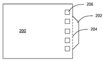
인쇄 회로 기판들(PCB: printed circuit boards)은 다른 전기 디바이스들 뿐만 아니라 많은 컴퓨터 로직 시스템들로 이루어진 기반의 핵심 구성요소이다. 제조 프로세스 동안, PCB들은 프로그램(program)되거나, 디버깅되거나 또는 그 외 데이터(data)를 송신 또는 수신하기 위해 통신될 수 있다. 이러한 프로세스 동안 PCB와 연관된 디바이스들 사이에 일정한 연결을 용이하게 하기 위해, PCB들은 보통 나중에 스냅 오프(snap off)되거나 그 외 제거될 수 있는 탭(tab)을 가지므로, PCB는 보다 큰 컴퓨터 또는 전기 시스템 내에 편리하게 설치될 수 있다. 그러나 제거에 앞서, 탭은 프로그래밍 및 디버깅을 용이하게 하기 위해 PCB와 연관된 외부 제조 디바이스들 사이의 반영구적인 연결을 용이하게 하도록 사용된다. 대안적으로, PCB는 프로그램되거나, 디버깅되거나 또는 그 외 복잡한 자동화된 디바이스들을 통해 통신될 수 있고, 그것은 PCB 상의 동시에 수많은 위치들에 전기적으로 접촉한다. PCB의 비용을 감소시키기 위해 및 많은 최종 사용자들이 현장에서 추가로 PCB를 프로그래밍하지 않기 때문에, 제조시, 프로그래밍 커넥터들은 전형적으로 PCB 상에 포함되지 않는다.Printed circuit boards (PCBs) are a key component of the foundation of many computer logic systems as well as other electrical devices. During the manufacturing process, PCBs may be programmed, debugged or otherwise communicated to send or receive data. To facilitate constant connection between devices associated with a PCB during this process, PCBs usually have tabs that can later be snapped off or otherwise removed, so that a PCB can be It can be conveniently installed in the system. However, prior to removal, tabs are used to facilitate semi-permanent connections between external fabrication devices associated with the PCB to facilitate programming and debugging. Alternatively, the PCB can be programmed, debugged or otherwise communicated through complex automated devices, which are in electrical contact with numerous locations on the PCB at the same time. In order to reduce the cost of the PCB and because many end users do not program the PCB further in the field, programming connectors are typically not included on the PCB.
그러나, 최초 제조 프로세스 다음에, 많은 목적들 또는 이유들을 위해 PCB와 통신하도록 PCB에 일시적으로 연결되는 것이 때때로 바람직하다. 예를 들어, 부가적인 또는 대안적인 프로그래밍을 업로드(upload)하도록 PCB와 통신하는 것, PCB를 추가로 디버깅하는 것, PCB를 진단 및/또는 수리하는 것 또는 그 외 PCB와 연관된 데이터를 송신 또는 수신하도록 PCB와 통신하는 것이 바람직할 수 있다. 그러나, 상기 논의된 바와 같이 탭의 제거 다음에 및 정교한 자동화의 부재시, 일시적으로 PCB와 연결됨으로써 PCB와 직접 통신하는 것은 어렵다. 그 결과로서, 다양한 포트(port)들 또는 다른 전자 커넥터들이 PCB 상에 종종 땜납되어, 외부 디바이스들은 PCB의 포트들 또는 전기 커넥터들에서 적절한 와이어(wire)들 및 상응하는 커넥터들을 통해 PCB에 편리하게 연결될 수 있다. 예를 들어, PCB 포트 또는 커넥터는 표준 전기 "수(male)" 구성요소일 수 있고, PCB에 연결되도록 의도된 디바이스는 상응하는 표준 "암(female)" 구성요소 또는 그 위에 칼라(collar)를 갖는 와이어가 구비될 수 있다(역 또한 가능). "암" 칼라가 "수" 구성요소와 짝을 이루므로, PCB는 효과적으로 접촉되고 통신될 수 있다.However, after the initial manufacturing process, it is sometimes desirable to be temporarily connected to the PCB to communicate with the PCB for many purposes or reasons. For example, communicating with the PCB to upload additional or alternative programming, further debugging the PCB, diagnosing and / or repairing the PCB, or sending or receiving data associated with the PCB. It may be desirable to communicate with the PCB so as to. However, following the removal of the tab and in the absence of sophisticated automation, as discussed above, it is difficult to communicate directly with the PCB by temporarily connecting with the PCB. As a result, various ports or other electronic connectors are often soldered onto the PCB so that external devices are conveniently connected to the PCB through the appropriate wires and corresponding connectors at the ports or electrical connectors of the PCB. Can be connected. For example, a PCB port or connector may be a standard electrical "male" component, and a device intended to be connected to a PCB may have a corresponding standard "female" component or collar thereon. With wire may be provided (or vice versa). Since the "female" collar is paired with the "male" component, the PCB can be effectively contacted and communicated.
다양한 포트들 및 커넥터들을 갖는 PCB를 구비하는 것은 PCB와 다른 외부 디바이스들 사이에 일시적으로 통신을 용이하게 하도록 작용하지만, PCB에 땜납된 포트들 또는 커넥터들은, 원하는 연결이 완료된 후 일반적으로 방치된다. 이는 증가된 비용들을 발생시킨다. 이러한 비용들은 다중 포트들 또는 커넥터들이 가변적 목적들을 위한 연결들을 용이하게 하도록 종종 요구되고-종종 방치된 다중 포트들/커넥터들을 발생시킨다는 사실로 인해 증가된다. 게다가, 현대 기술에서 공통적인 점점 작은 컴퓨팅 및 전기 디바이스들에 있어서, 연관 디바이스 내에 설치될 때, 소정의 PCB 상에 보유된 부피가 큰 또는 공간 소비적인 포트들/커넥터들을 갖는 것은 종종 바람직하지 않다. 그러나, 포트들/커넥터들의 제거는 PCB에 대한 손상을 발생시키고, 마찬가지로 나중에 필요하면 또는 원한다면, PCB가 추가의 프로그래밍, 디버깅 및 기타 동등한 것을 위해 현장에서 차후에 연결될 수 있는 편리성을 감소시킨다.Having a PCB with various ports and connectors serves to facilitate communication temporarily between the PCB and other external devices, but the ports or connectors soldered to the PCB are generally left after the desired connection is complete. This results in increased costs. These costs are increased due to the fact that multiple ports or connectors often generate multiple ports / connectors that are often required and neglected to facilitate connections for variable purposes. In addition, for the increasingly smaller computing and electrical devices common in modern technology, it is often undesirable to have bulky or space consuming ports / connectors held on a given PCB when installed in an associated device. However, the removal of ports / connectors causes damage to the PCB and likewise reduces the convenience of the PCB being later connected in the field for further programming, debugging and other equivalents, if necessary or later.
PCB의 포트들/커넥터들이 그대로 방치된다면, 부가적인 단점이 존재한다. 복잡하거나 정교한 PCB들에서 특정 목적을 완수하도록 적절한 포트 또는 커넥터와 위치하는 것 및/또는 짝을 이루는 것이 종종 부담스럽거나 어려울 수 있다. 게다가, 최종 사용자가 PCB에 연결하는 것을 원한다면, 연관된 와이어링 및 상응하는 커넥터는 사용자에게 부가적인 비용들을 필수적으로 발생시킨다. 그러한 비용들은 상당할 수 있다. 게다가, 그들을 짝을 이루도록 시도할 시 사용자가 PCB 포트/커넥터 또는 상응하는 와이어링 또는 커넥터를 손상한다면, 이는 부가적인 비용들을 발생시킬 수 있다. 궁극적으로, 현재 기법들 하에서 제조 프로세스가 완료된 후 PCB에 연결하는 것과 관련된 비용들은 최소한, 두 개의 커넥터들 즉, PCB 상에 하나 및 와이어 상에 다른 하나를 포함한다. 사용자가 임의의 실수들을 행한다면, 비용들은 상당히 상승한다.If the ports / connectors of the PCB are left untouched, there are additional disadvantages. It may often be burdensome or difficult to locate and / or mate with the appropriate port or connector to accomplish a particular purpose in complex or sophisticated PCBs. In addition, if the end user wants to connect to the PCB, the associated wiring and corresponding connector necessarily incur additional costs for the user. Such costs can be significant. In addition, if the user damages the PCB port / connector or corresponding wiring or connector when attempting to pair them, this may incur additional costs. Ultimately, the costs associated with connecting to a PCB after the manufacturing process is completed under current techniques include at least two connectors, one on the PCB and the other on the wire. If the user makes any mistakes, the costs go up significantly.
본 발명의 구현은 컴퓨터 시스템들 및 컴퓨터 시스템 동작의 다양한 측면들의 지능형 유연 관리 및 감시를 위한 시스템들 및 방법들을 제공한다. 본 발명의 구현들은 다양한 범용 컴퓨터 시스템들 및 다양한 특수 용도 컴퓨터 시스템들을 포함하는, 다양한 기존 및 장래의 컴퓨터 시스템들에 적용가능하다. 본 발명이 다양한 방법들로 구현될 수 있는 컴퓨터 시스템의 하나의 분류 또는 구성은 발명의 명칭이 Non-Peripherals Processing Control Module Having Improved Heat Dissipating Properties인 미국 특허 제7,256,991호, 발명의 명칭이 Robust Customizable Computer Processing System인 제7,242,574호, 및 발명의 명칭이 Systems and Methods for Providing a Dynamically Modular Processing Unit인 제7,075,784호에 개시되어 있으며, 그들은 모든 발명을 위해 본 출원에 참고문헌으로 명백히 통합되어 있다.The implementation of the present invention provides systems and methods for intelligent flexible management and monitoring of computer systems and various aspects of computer system operation. Implementations of the invention are applicable to a variety of existing and future computer systems, including various general purpose computer systems and various special purpose computer systems. One classification or configuration of a computer system in which the present invention may be implemented in various ways is described in US Pat. No. 7,256,991, entitled Non-Peripherals Processing Control Module Having Improved Heat Dissipating Properties, entitled Robust Customizable Computer Processing. System 7,242,574, and the name of the invention are disclosed in Systems and Methods for Providing a Dynamically Modular Processing Unit, 7,75,784, which are expressly incorporated herein by reference for all inventions.
복수의 상호 접속 회로 기판들을 갖고 사용하도록 구성된 컴퓨터 시스템에서, 본 발명의 어떤 구현들은 인증된 회로 기판들만이 컴퓨터 시스템에 사용되는 것을 보증하기 위한 시스템을 제공한다. 상기 시스템은 각각의 상기 회로 기판들 상에 위치된 인증 칩(chip)을 포함한다. 각 인증 칩은 1) 기능을 위한 상기 컴퓨터 및 기능을 위한 상기 인증 칩이 위치되는 상기 회로 기판에 필요한 핵심 기능 및 2) 상기 컴퓨터 시스템에서 적절히 기능하기 위해 상기 회로 기판이 테스트되어 인증된 것을 전달하는 인증 기능을 포함한다. 또한, 상기 시스템은 상기 시스템에 통합된 각 회로 기판의 인증된 상태를 검증하기 위해 각각의 상기 인증 칩들이 서로 통신하는 것을 가능하게 하는 인증 통신들 버스를 포함한다. 적어도 일부 그러한 시스템들에 있어서, 상기 인증 칩이 없는 회로 기판이 상기 컴퓨터 시스템에 부착되면, 각각의 인증 칩은 상기 컴퓨터 시스템이 기능하는 것을 방지하도록 구성된다.In a computer system configured for use with a plurality of interconnect circuit boards, certain implementations of the invention provide a system to ensure that only authorized circuit boards are used in a computer system. The system includes an authentication chip located on each of the circuit boards. Each authentication chip conveys 1) the key functionality required for the computer for the function and the circuit board on which the authentication chip for the function is located and 2) the circuit board has been tested and certified for proper functioning in the computer system. It includes an authentication function. The system also includes an authentication communications bus that enables each of the authentication chips to communicate with each other to verify an authenticated state of each circuit board integrated in the system. In at least some such systems, if a circuit board without the authentication chip is attached to the computer system, each authentication chip is configured to prevent the computer system from functioning.
어떤 구현들에서, 각 인증 칩은 그의 각 회로 기판상에서 조건들을 감시하도록 구성된다. 상기 인증 칩들은 상기 회로 기판들 상에서 감시된 조건들의 기록을 유지할 수 있고, 각 인증 칩은 그의 각 회로 기판상에서 조건들의 보고들을 송신하도록 구성될 수 있다.In some implementations, each authentication chip is configured to monitor conditions on its respective circuit board. The authentication chips may maintain a record of conditions monitored on the circuit boards, and each authentication chip may be configured to transmit reports of conditions on each circuit board thereof.
각 인증 칩이 상기 컴퓨터 시스템에 대한 전력 제어에 지능적으로 관여하도록 구성되는 일부 구현들에서, 상기 인증 칩들은 상기 컴퓨터 시스템에 대한 복수의 전원들을 턴 온 및 오프하는 타이밍(timing)에 협력적으로 관여한다. 일부 그러한 실시예들에 있어서, 상기 인증 칩들은 상기 컴퓨터의 전원들을 칩 안전 순서로 순차적으로 턴 온함으로써 및 순차적인 순서로 이전의 모든 전원들이 적절히 턴 온된 것을 검증한 후에만, 상기 컴퓨터 시스템의 칩들을 파괴할 위험이 있는 것으로 알려져 있는 상기 컴퓨터 시스템 내의 전력 조건들의 존재를 공동으로 방지한다. 추가적으로 또는 대안적으로, 상기 인증 칩들은 상기 컴퓨터 시스템 내의 전원 고장의 검출 시에 방치되면 칩들에 손상을 초래할 수 있는 전원들을 신속히 턴 오프함으로써, 상기 컴퓨터 시스템의 칩들을 파괴할 위험이 있는 것으로 알려져 있는 상기 컴퓨터 시스템 내의 전력 조건들의 상기 존재를 공동으로 방지한다.In some implementations in which each authentication chip is configured to intelligently participate in power control for the computer system, the authentication chips cooperatively participate in timing to turn on and off a plurality of power sources for the computer system. do. In some such embodiments, the authentication chip is a chip of the computer system only after sequentially turning on the power supplies of the computer in chip safety order and after verifying that all previous power supplies are properly turned on in sequential order. Jointly prevent the presence of power conditions in the computer system that are known to be at risk of destroying them. Additionally or alternatively, the authentication chips are known to be at risk of destroying chips in the computer system by quickly turning off the power sources, which, if left undetected upon detection of a power failure in the computer system, may cause damage to the chips. Jointly prevent the presence of power conditions within the computer system.
적어도 일부 구현들에 있어서, 상기 인증 칩들은 전력 제어를 감시하고 상기 전원들의 활성화 및 비활성화를 제어하도록 구성된 로직 게이트(logic gate)들을 포함하며, 그것에 의해 전원의 고장시 다른 전원들의 비활성화는 상기 컴퓨터 시스템에 대한 손상을 방지하기 위해 충분히 신속해진다. 적어도 일부 실시예들에 있어서, 다른 전원들의 비활성화는 수개 내지 소수의 클록 사이클(clock cycle)들 내에서 발생한다.In at least some implementations, the authentication chips include logic gates configured to monitor power control and control activation and deactivation of the power supplies, whereby deactivation of other power supplies in the event of a power failure is caused by the computer system. Becomes fast enough to avoid damage to it. In at least some embodiments, deactivation of other power supplies occurs within several to few clock cycles.
구현된 바와 같이, 상기 컴퓨터 시스템이 턴 오프될지라도, 상기 인증 칩들은 상기 컴퓨터 시스템이 전원에 연결되어 있는 임의의 시간에 동작할 수 있다. 상기 인증 칩들은 상기 컴퓨터 시스템들의 측파대(sideband) 관리를 수행하고, 로직 게이트들만을 사용하여 그렇게 행할 수 있다.As implemented, even when the computer system is turned off, the authentication chips may operate at any time the computer system is connected to a power source. The authentication chips can perform sideband management of the computer systems and do so using only logic gates.
어떤 구현들에서, 고장 이벤트들이 상기 인증 칩들 내의 로직 게이트들에 의해 검출되어 기록되고, 그 후에 상기 인증 칩들은 상기 고장 이벤트들을 협력적으로 로그(log)하고 상기 컴퓨터 시스템을 셧 다운(shut down)하도록 구성된다. 상기 인증 칩들은 다음 파워 온(power-on) 시도 중 하나 이상에, 및 고장시 언제라도 상기 고장 이벤트들의 기록을 송신하도록 구성될 수 있다.In some implementations, fault events are detected and recorded by logic gates in the authentication chips, after which the authentication chips cooperatively log the failure events and shut down the computer system. It is configured to. The authentication chips may be configured to transmit a record of the failure events at one or more of the next power-on attempts and at any time upon failure.
일부 구현들에서, 상기 컴퓨터 시스템이 실행되고 있을 때, 상기 인증 칩들은 내부 집적 회로(I2C: inter-integrated circuit) 버스, 및 낮은 핀 카운트(LPC: low pin count) 버스와 같은, 상기 컴퓨터 시스템의 하나 이상의 버스들 상에 발생하는 통신들을 스누프(snoop)하도록 구성된다. 상기 인증 칩들은 입력/출력(I/O: inout/output) 통신들 및 포스트 코드(post code)들과 같은, 스누프된 통신들에 응답하도록 구성될 수 있다.In some implementations, when the computer system is running, the authentication chips are the computer, such as an inter-integrated circuit (I 2 C) bus, and a low pin count (LPC) bus. Configured to snoop communications occurring on one or more buses of the system. The authentication chips may be configured to respond to snooped communications, such as in / out (output / output) I / O communications and post codes.
본 발명의 구현들에서, 하나 이상의 상기 인증 칩들은 로직 게이트들을 사용하여 실시간 프로세서 에뮬레이션(emulation)을 제공하도록 구성된다. 실시간 프로세서 에뮬레이션을 제공하는 상기 하나 이상의 인증 칩들은 선택된 입력들을 위해 특정하게 선택된 출력들을 자동으로 및 신속히 제공할 수 있다. 어떤 경우들에서, 상기 하나 이상의 인증 칩들은 키보드 컨트롤러(keyboard controller) 및 비디오 컨트롤러(video controller) 중 하나에 에뮬레이션을 제공한다.In implementations of the invention, one or more of the authentication chips are configured to provide real time processor emulation using logic gates. The one or more authentication chips providing real time processor emulation can automatically and quickly provide specifically selected outputs for selected inputs. In some cases, the one or more authentication chips provide emulation to one of a keyboard controller and a video controller.
어떤 구현들에서, 상기 인증 칩들은, 전원이 초기에 상기 컴퓨터 시스템에 연결될 때, 상기 컴퓨터 시스템이 턴 온되어 사용되는 것을 가능하게 하기 전에 각각이 활성화되어 기능할 준비가 되는 것을 보증하기 위해 상기 인증 칩들이 서로에 통신들을 제공하도록 구성된다.In some implementations, the authentication chips are configured to ensure that when a power source is initially connected to the computer system, each of the authentication chips is activated and ready to function before enabling the computer system to be turned on and used. The chips are configured to provide communications to each other.
어떤 구현들은 컴퓨터 시스템에서 나타나고, 여기서 상기 컴퓨터 시스템의 통합된 측파대 관리를 제공하기 위한 시스템은 상기 컴퓨터 시스템에 통합되고 로직 게이트들만을 사용하여 상기 컴퓨터 시스템의 측파대 관리를 제공하는 측파대 관리 디바이스를 사용하여 제공된다. 상기 측파대 관리 디바이스는 파워 업 시에 상기 컴퓨터 시스템의 전원들의 활성화의 적절한 시퀀싱을 보증하는 파워 온 관리를 제공할 수 있다. 상기 측파대 관리 디바이스는 부적절하고, 잠재적으로 손상되는, 전압 조합들이 상기 컴퓨터 시스템에서 발생하는 것을 방지하는 방법으로 전원들의 활성화만이 발생하는 것을 보증할 수 있다. 상기 측파대 관리 디바이스는 전원 시퀀싱을 중단하고, 상기 컴퓨터 시스템을 턴 오프하며, 하나 이상의 전원들이 활성화되지 않을 때 결함 상태의 상세를 로그하도록 구성될 수 있다.Some implementations appear in a computer system, where a system for providing integrated sideband management of the computer system is integrated into the computer system and provides sideband management of the computer system using only logic gates. Is provided using. The sideband management device may provide power on management to ensure proper sequencing of activation of the power sources of the computer system upon power up. The sideband management device can ensure that only activation of power sources occurs in a way that prevents inappropriate, potentially damaging, voltage combinations from occurring in the computer system. The sideband management device can be configured to stop power sequencing, turn off the computer system, and log details of a fault condition when one or more power supplies are not active.
어떤 구현들의 측파대 관리 디바이스는 상기 컴퓨터 시스템의 다중 회로 기판들에 걸쳐서 분배된 복수의 디바이스들을 포함할 수 있다. 그럼에도 불구하고, 상기 측파대 관리 디바이스는 상기 컴퓨터 시스템이 턴 오프될 때 전원 공급된 채로 남아 있을 수 있다. 어떤 구현들에 있어서, 상기 컴퓨터 시스템은 단일 컴퓨터 디바이스이고, 상기 측파대 관리 디바이스는 상기 컴퓨터 디바이스의 적어도 하나의 회로 기판에 통합되며, 그것에 의해 상기 측파대 관리 디바이스는 개별 프로세서 또는 컴퓨터 디바이스를 포함하지 않는다.Sideband management devices in certain implementations can include a plurality of devices distributed across multiple circuit boards of the computer system. Nevertheless, the sideband management device may remain powered on when the computer system is turned off. In some implementations, the computer system is a single computer device, and the sideband management device is integrated into at least one circuit board of the computer device, whereby the sideband management device does not include a separate processor or computer device. Do not.
본 발명의 구현들은 컴퓨터 시스템의 기능에 필요한 상이한 전압들의 복수의 전원들을 포함하는 상기 컴퓨터 시스템에서 전원들의 활성화를 제어하기 위한 방법을 제공한다. 상기 방법은 상기 복수의 전원들 중 하나 이상의 활성화를 선택적으로 지시하는 단계 및 활성화되도록 지시된 상기 전원 및 전원들이 적절히 턴 온되는지를 감시하는 단계를 포함한다. 활성화되도록 지시된 상기 전원들 중 하나 이상이 설정 시간 내에 적절히 턴 온되지 않을 때, 상기 방법은 고장 이벤트를 로그하는 것 및 상기 컴퓨터 시스템을 턴 오프하는 단계를 포함한다.Implementations of the present invention provide a method for controlling activation of power supplies in a computer system that includes a plurality of power supplies of different voltages required for the functionality of the computer system. The method includes selectively instructing activation of one or more of the plurality of power sources and monitoring whether the power source and the power sources indicated to be activated are properly turned on. When one or more of the power supplies instructed to be activated are not properly turned on within a set time, the method includes logging a failure event and turning off the computer system.
상기 방법의 일부 구현들에 있어서, 전원들은 부적절한 전압 시퀀스들에 의해 초래되는 상기 컴퓨터 시스템의 구성요소들에 대한 손상을 방지하도록 설계된 시퀀스에서 활성화되고, 각 전원의 활성화는 활성화의 시퀀스가 연속되기 전에 적절한 활성화를 위해 감시된다. 적어도 일부 실시예들에 있어서, 상기 컴퓨터 시스템을 턴 오프하는 것은 부적절한 전압 시퀀스들에 의해 초래되는 상기 컴퓨터 시스템의 구성요소들에 대한 손상을 방지하는 순서로 실행가능해지는 임의의 전원들을 비활성화하는 것을 포함한다.In some implementations of the method, the power supplies are activated in a sequence designed to prevent damage to the components of the computer system caused by inappropriate voltage sequences, and activation of each power supply is performed before the sequence of activation is continued. Monitored for proper activation. In at least some embodiments, turning off the computer system includes disabling any power supplies that become executable in an order that prevents damage to the components of the computer system caused by inappropriate voltage sequences. do.
본 발명의 구현들은 복수의 회로 기판들을 갖는 컴퓨터 시스템을 위해 전력 관리 시스템을 제공한다. 상기 전력 관리 시스템은 상기 컴퓨터 시스템의 상기 회로 기판들에 걸쳐서 확장되는 전력 관리 버스 및 상기 전력 관리 버스에 통신적으로 결합된 복수의 플랫폼(platform) 관리 컨트롤러들을 포함하며, 여기서 각 플랫폼 관리 컨트롤러는 상이한 회로 기판 상에 위치되고 그의 각 회로 기판 상에서 전원들을 제어하도록 구성된다.Implementations of the present invention provide a power management system for a computer system having a plurality of circuit boards. The power management system includes a power management bus that extends across the circuit boards of the computer system and a plurality of platform management controllers communicatively coupled to the power management bus, wherein each platform management controller is different. Located on the circuit board and configured to control the power supplies on each circuit board thereof.
적어도 일부 구현들에 있어서, 각 플랫폼 관리 컨트롤러는 전적으로 로직 게이트들로 구현된다. 상기 플랫폼 관리 컨트롤러들은 컴퓨터가 턴 온되는지에 관계없이, 상기 컴퓨터 시스템이 입력 전원에 연결되는 언제라도 동작하도록 구성될 수 있다. 또한, 상기 플랫폼 관리 컨트롤러들은 상기 컴퓨터 시스템의 임의의 전원들이 활성화되는 것을 가능하게 하기 전에 다른 플랫폼 관리 컨트롤러들이 활성되는 것을 보증하도록 구성될 수 있다. 상기 플랫폼 관리 컨트롤러들은 상기 전력 관리 버스를 사용하여 다른 컨트롤러들이 활성될 때 수신되는 바와 같이 다른 컨트롤러들에 통과되어 다른 컨트롤러들에 의해 전달되는 컨트롤러 특정 키(key)들을 발생시킴으로써 다른 플랫폼 관리 컨트롤러들이 활성화되는 것을 결정할 수 있으며, 그것에 의해 각 컨트롤러가 그 자체의 키를 다시 수신할 때 그것은 모든 컨트롤러들이 활성되는 것을 인식한다.In at least some implementations, each platform management controller is entirely implemented with logic gates. The platform management controllers may be configured to operate any time the computer system is connected to an input power source, regardless of whether the computer is turned on. Further, the platform management controllers can be configured to ensure that other platform management controllers are activated before enabling any power sources of the computer system to be activated. The platform management controllers use the power management bus to activate other platform management controllers by generating controller specific keys passed to and passed by the other controllers, as received when other controllers are activated. It can determine that, by means of which each controller receives its own key again it recognizes that all controllers are active.
본 발명의 구현은 컴퓨터 시스템의 속도를 개선하면서 상기 컴퓨터 시스템 내의 프로세서 기반 컴퓨터 구성요소를 에뮬레이션하기 위한 시스템을 제공한다. 상기 프로세서 기반 컴퓨터 구성요소를 에뮬레이션하기 위한 시스템은 로직 게이트들만을 사용하여 프로세서 기반 컴퓨터 구성요소를 에뮬레이션하도록 구성된 로직 게이트 기반 디바이스를 포함하며, 여기서 상기 로직 게이트들은 프로세서 기반 컴퓨터 구성요소에 의해 통상 취급되는 명령들의 세트를 수신하고 단지 훨씬 더 빠른 속도로 상기 프로세서 기반 컴퓨터 구성요소에 의해 통상 출력되는 출력을 제공하도록 구성된다. 일부 구현들에 있어서, 상기 로직 게이트들은 상기 프로세서 기반 컴퓨터 구성요소에 의해 통상 취급되는 모든 가능한 명령들의 서브세트(subset)만을 인지하고 응답하도록 구성된다. 상기 로직 게이트 기반 디바이스는 상기 컴퓨터 시스템에 의해 활성적으로 사용되지 않는 레거시(legacy) 컴퓨터 디바이스의 에뮬레이션을 제공할 수 있지만 그의 존재는 1) 상기 컴퓨터 시스템의 기본 입력/출력 시스템(BIOS: basic input/output system) 및 2) 컴퓨터 시스템의 운영 체제(OS: operating system) 중 하나의 적절한 동작에 요구된다.Implementations of the present invention provide a system for emulating processor-based computer components within a computer system while improving the speed of the computer system. The system for emulating the processor-based computer component includes a logic gate-based device configured to emulate a processor-based computer component using only logic gates, where the logic gates are typically handled by a processor-based computer component. Receive a set of instructions and provide output that is typically output by the processor-based computer component only at a much faster rate. In some implementations, the logic gates are configured to recognize and respond to only a subset of all possible instructions typically handled by the processor-based computer component. The logic gate based device may provide an emulation of a legacy computer device that is not actively used by the computer system, but its presence is 1) basic input / output system (BIOS) of the computer system. output system) and 2) the proper operation of one of the computer's operating systems (OS).
본 발명의 어떤 구현들은 디지털 통신들을 인코딩(encoding), 송신, 및 디코딩(decoding)하기 위한 방법을 제공하며, 여기서 통신의 데이터 부분들은 본래 추가 데이터 비트(bit)들를 필요로 하지 않고 수신된 데이터 부분들의 유효성에 관한 체크섬(checksum) 정보를 포함한다. 상기 방법은 디지털 데이터의 어떤 패턴(pattern)들이 무효인 방식을 사용하여 정보를 디지털 스트림(digital stream)으로 인코딩하는 단계 및 송신기를 반복적으로 사용하여 상기 디지털 스트림을 송신하는 단계를 포함한다. 수신기는 수신된 정보를 수신하고, 상기 수신된 정보는 유효 및 무효 패턴들에 대해 평가된다. 유효 개시 패턴 다음에 하나 이상의 유효 데이터 패턴들이 뒤따를 때, 상기 수신된 정보는 단지 유지되고 디코딩된다.Certain implementations of the present invention provide a method for encoding, transmitting, and decoding digital communications, wherein the data portions of the communication do not originally require additional data bits and are received data portions. It contains checksum information about the validity of the data. The method includes encoding information into a digital stream using a manner in which certain patterns of digital data are invalid and transmitting the digital stream repeatedly using a transmitter. The receiver receives the received information, which is evaluated for valid and invalid patterns. When one or more valid data patterns are followed by a valid start pattern, the received information is only maintained and decoded.
상기 개시 패턴은 상기 데이터 스트림에 포함되는 데이터의 유형에 관한 정보를 포함할 수 있다. 또한, 상기 개시 패턴은 상기 디지털 스트림이 반복된 횟수에 관한 정보를 포함할 수 있다.The initiation pattern may include information about a type of data included in the data stream. In addition, the start pattern may include information on the number of times the digital stream is repeated.
본 발명의 구현은 컴퓨터 시스템에 통합된 플랫폼 관리 컨트롤러를 사용하여 상기 컴퓨터 시스템의 시동 및 기능을 감시하기 위한 방법을 제공한다. 상기 방법은 컴퓨터 시스템에 플랫폼 관리 컨트롤러를 제공하는 단계를 포함하며, 여기서 상기 플랫폼 관리 컨트롤러는 상기 컴퓨터 시스템의 전력을 관리하고 상기 컴퓨터 시스템의 기능에 관한 정보를 상기 컴퓨터 시스템으로부터 획득할 수 있도록 상기 컴퓨터 시스템에 연결되고, 여기서 상기 플랫폼 관리 컨트롤러는 송신기에 동작적으로 연결된다. 또한, 상기 방법은 상기 컴퓨터 시스템의 시동 및 동작을 감시하기 위해 상기 플랫폼 관리 컨트롤러를 사용하는 단계, 상기 컴퓨터 시스템의 시동 및 동작 중 적어도 하나에 관한 이벤트들에 로그하기 위해 상기 플랫폼 관리 컨트롤러를 사용하는 단계, 및 상기 송신기를 사용하여 로그된 이벤트들을 송신하기 위해 상기 플랫폼 관리 컨트롤러를 사용하는 단계를 포함한다.Implementations of the present invention provide a method for monitoring the startup and functionality of a computer system using a platform management controller integrated into the computer system. The method includes providing a platform management controller to a computer system, where the platform management controller is capable of managing power of the computer system and obtaining information from the computer system about the functionality of the computer system. Coupled to the system, wherein the platform management controller is operatively coupled to the transmitter. The method also uses the platform management controller to monitor startup and operation of the computer system, and uses the platform management controller to log events relating to at least one of the startup and operation of the computer system. And using the platform management controller to transmit logged events using the transmitter.
상기 로그된 이벤트들은 시동시 상기 컴퓨터 시스템에 의해 발생된 포스트 코드들을 포함할 수 있다. 상기 로그된 이벤트들이 포스트 코드들을 포함할 때, 상기 플랫폼 관리 컨트롤러는 시동시 언제라도 상기 포스트 코드들을 송신할 수 있다. 상기 로그된 이벤트들은 셧다운(shutdowm) 시간 및 검출된 비정상 온도의 시간 중 하나에서 상기 컴퓨터 시스템으로부터 획득된 온도 판독을 추가적으로 또는 대안적으로 포함할 수 있다. 일부 구현들에 있어서, 상기 컴퓨터 시스템의 운영 시스템은 외부 송신을 위해 상기 플랫폼 관리 컨트롤러에 메시지들을 전송하도록 구성된다.The logged events may include post codes generated by the computer system at startup. When the logged events include post codes, the platform management controller can send the post codes at any time upon startup. The logged events may additionally or alternatively include a temperature reading obtained from the computer system at one of a shutdown time and a time of detected abnormal temperature. In some implementations, the operating system of the computer system is configured to send messages to the platform management controller for external transmission.
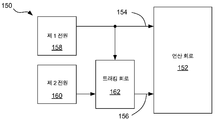
본 발명의 구현들은 전원 트래킹 장치를 제공하기 위한 기술에 관한 것이다. 특히, 본 발명의 적어도 일부 구현들은 연산 회로의 제 1 전력 입력이 상기 연산 회로의 제 2 전력 입력에 대해 미리 정의된 관계를 유지하는 것을 보증하기 위한 전원 트래킹 장치에 관한 것이다.Implementations of the invention relate to techniques for providing a power tracking device. In particular, at least some implementations of the present invention relate to a power tracking device for ensuring that a first power input of an arithmetic circuit maintains a predefined relationship to a second power input of said arithmetic circuit.
본 발명의 구현은 기준 전압원, 비교기, 및 스위치를 갖는 전원 트래킹 장치를 포함한다. 상기 기준 전압원은 기준 전압을 비교기의 제 1 입력에 제공한다. 상기 비교기의 제 2 입력은 제 1 전력 입력에 결합된다. 상기 비교기의 출력은 상기 기준 전압 및 상기 제 1 전력 입력의 상대 전압의 함수로서 상태를 스위칭한다. 상기 비교기의 상기 출력은 스위치를 제어하고, 따라서 상기 기준 전압 및 상기 제 1 전력 입력의 상기 상대 전압에 따라 상기 스위치를 개방 및 폐쇄한다. 상기 스위치는 전원과 상기 제 2 전력 입력 사이에 배치된다. 따라서, 상기 제 2 전력 입력은 상기 제 1 전력 입력에 대해 미리 정의된 관계로 유지될 수 있다.Implementations of the present invention include a power supply tracking device having a reference voltage source, a comparator, and a switch. The reference voltage source provides a reference voltage to the first input of the comparator. The second input of the comparator is coupled to the first power input. The output of the comparator switches state as a function of the relative voltage of the reference voltage and the first power input. The output of the comparator controls the switch, thus opening and closing the switch in accordance with the reference voltage and the relative voltage of the first power input. The switch is disposed between a power source and the second power input. Thus, the second power input may be maintained in a predefined relationship with respect to the first power input.
본 발명의 구현들의 방법들 및 프로세스들은 개인용 컴퓨팅 엔터프라이즈(enterprise)들의 영역에 특히 유용한 것으로 증명되었을지라도, 당업자들은 제어 시스템들 또는 스마트 인터페이스 시스템(smart-interface system)들을 사용하는 임의의 산업에 대한 엔터프라이즈들 및/또는 그러한 디바이스들의 상기 구현으로 이득을 얻는 엔터프라이즈들을 포함하는, 커스터마이즈(customize) 가능 엔터프라이즈들을 산출하기 위해, 본 발명의 상기 방법들 및 프로세스들이 각종 상이한 애플리케이션들 및 각종 상이한 제조 영역들에 사용될 수 있다는 것을 인식할 것이다. 그러한 산업들의 예들은 자동차 산업들, 항공 전자 산업들, 유압 제어 산업들, 오토/비디오 제어 산업들, 전기통신 산업들, 의료 산업들, 특수 용도 산업들, 및 가전 기기 산업들을 포함하지만, 이들에 제한되지 않는다. 따라서, 본 발명의 상기 시스템들 및 방법들은 현재 컴퓨터 기술에 의해 종래에 이용되지 않았던 마켓(market)들을 포함하는 많은 상이한 마켓들에 이점들을 제공할 수 있다.Although the methods and processes of the implementations of the present invention have proved to be particularly useful in the area of personal computing enterprises, those skilled in the art will appreciate that an enterprise may be an enterprise for any industry using control systems or smart-interface systems. The methods and processes of the present invention may be used in a variety of different applications and a variety of different manufacturing areas to produce customizable enterprises, including enterprises that benefit from the implementation of such devices and / or such devices. You will recognize that you can. Examples of such industries include, but are not limited to, automotive industries, avionics, hydraulic control industries, auto / video control industries, telecommunications industries, medical industries, special purpose industries, and consumer electronics industries. It is not limited. Thus, the systems and methods of the present invention can provide advantages to many different markets, including markets that have not previously been used by current computer technology.
본 발명의 구현은 컴퓨터 시스템들 진단 정보를 무선으로 수신하고 그러한 정보를 커스터마이즈 가능하게 표시하기 위한 시스템들 및 방법들을 제공한다. 상기 정보는 다양한 범용 컴퓨터 시스템들 및 다양한 특수 용도 컴퓨터 시스템들을 포함하는, 다양한 기존 및 장래의 컴퓨터 시스템들로부터 수신될 수 있다. 본 출원에 개시된 바와 같이, 컴퓨터 시스템에 통합된 플랫폼 관리 컨트롤러(PMC: platform management controller) 또는 유사한 디바이스는 컴퓨터 시스템 정보를 감시하고 상기 감시된 정보를, 예컨대 적외선에 의해 송신하거나 그 외 전달한다. 본 발명의 실시예들은 상기 송신된 정보를 수신하므로, 그것은 본 출원에 개시된 것과 같은 다양한 목적들에 이용될 수 있다.The implementation of the present invention provides systems and methods for wirelessly receiving computer systems diagnostic information and customizing the display of such information. The information may be received from various existing and future computer systems, including various general purpose computer systems and various special purpose computer systems. As disclosed herein, a platform management controller (PMC) or similar device integrated into a computer system monitors computer system information and transmits or otherwise transmits the monitored information, such as by infrared. Since embodiments of the present invention receive the transmitted information, it can be used for various purposes as disclosed in this application.
본 발명의 구현들에 있어서, PMC 또는 다른 유사한 디바이스에 의해 송신된 복수의 로그된 이벤트들은 무선 진단 디바이스와 같은 진단 디바이스에 의해 수신 및 감시될 수 있다. 본 발명의 적어도 일부 구현들에 있어서, 진단 디바이스의 프로세싱 특징들은 주로 또는 전적으로 로직 게이트들로 구현된다. 그러한 구현은 본 출원에서 더 상세히 논의되는 바와 같이 어떤 장점들을 제공한다.In implementations of the invention, a plurality of logged events sent by a PMC or other similar device may be received and monitored by a diagnostic device, such as a wireless diagnostic device. In at least some implementations of the invention, the processing features of the diagnostic device are mainly or wholly implemented with logic gates. Such an implementation provides certain advantages as discussed in more detail herein.
본 발명의 구현은 일시적 전기 연결들에 관한 것이다. 특히, 본 발명은 인쇄 회로 기판(PCB)로부터 또는 PCB에 정보를 수신 또는 송신하기 위해, 외부 디바이스를 PCB에 일시적으로 연결하기 위한 시스템들 및 방법들에 관한 것이다.The implementation of the present invention relates to transient electrical connections. In particular, the present invention relates to systems and methods for temporarily connecting an external device to a PCB for receiving or transmitting information to or from a printed circuit board (PCB).
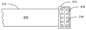
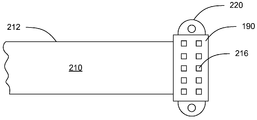
본 발명의 구현은 상기 연결을 통해서 데이터의 상기 전송을 용이하게 하기 위해 외부 소스와 PCB 사이의 일시적 전기 연결들과 관련하여 실시된다. 적어도 하나의 구현에 있어서, 일시적 전기 시스템은 PCB의 하나 이상의 에지(edge)들에 인접하여 배치된 전기 접촉 패드들을 갖는 PCB를 포함한다. 상기 전기 접촉 패드들은 차례로 PCB 상의 특정 위치들에 전기적으로 연결된다. 상기 시스템들은 와이어 리본(wire ribbon) 및 상기 PCB의 상기 에지(들) 상에 배치된 상기 전기 패드들에 대응하는 하나 이상의 전기 접촉 패드들이 배치된 전선 리본(electrical wire ribbon)의 원위 단부의 헤드(head)를 차례로 포함하는 일시적 전기 커넥터 장치를 더 포함한다.Implementations of the invention are practiced in connection with transient electrical connections between an external source and a PCB to facilitate the transfer of data through the connection. In at least one implementation, the temporary electrical system includes a PCB having electrical contact pads disposed adjacent one or more edges of the PCB. The electrical contact pads are in turn electrically connected to specific locations on the PCB. The systems may include a head of a distal end of an electrical wire ribbon having a wire ribbon and one or more electrical contact pads corresponding to the electrical pads disposed on the edge (s) of the PCB. and a temporary electrical connector device which in turn comprises a head).
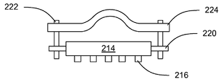
추가 구현에 있어서, PCB와 일시적으로 전기적으로 연결되도록 적응된 장치는 전선 리본을 포함한다. 상기 장치는 하나 이상의 전기 접촉 패드들이 배치된 상기 전선 리본의 상기 원위 단부에 헤드를 더 포함한다. 또한, 일부 구현들에 있어서, 상기 헤드는 그 위에 배치된 접착제를 가지며, 이는 전기 접촉 패드들을 실질적으로 둘러싼다. 사용 전에, 상기 접착제는 사용시에 제거될 수 있는 논-스틱 페이퍼 백킹(non-stick paper backing) 등에 의해 보호된다. 다른 구현에 있어서, 상기 헤드는 상기 헤드를 팽팽하게 하도록 조작될 수 있는 압축 피팅(compression fitting)을 포함하여, 그것은 PCB와 같은 대응하는 표면에 고정된 채로 일시적으로 남아 있는다. 또 다른 구현들에 있어서, 상기 헤드는 상기 헤드 및 PCB와 같은 대응하는 표면 사이에서 일시적 연결을 용이하게 하는데 사용될 수 있는 핀(pin)들 또는 다른 로케이터(locator)들을 포함한다. 더 다른 구현에 있어서, 상기 헤드는 조우(jaw)들을 폐쇄된 위치에서 바이어스(biase)하는 동작 스프링(spring)에 의해 연결된 2개의 대향하는 조우들로 구성되어, 상기 조우들은 사용자에 의해 선택적으로 개방될 수 있고 상기 헤드는 PCB와 같은 대응하는 표면에 일시적으로 "클립(clip)"된다. 또 다른 구현들에 있어서, 헤드는 PCB의 폭을 연계하여 분리한 2개의 대향하는 고정 표면들로 구성되어, 상기 헤드는 이에 일시적으로 고정된 채로 남아 있기 위해 상기 PCB의 상기 에지에 걸쳐서 일시적으로 슬립(slip)될 수 있다.In a further implementation, a device adapted to temporarily electrically connect with a PCB includes a wire ribbon. The apparatus further includes a head at the distal end of the wire ribbon on which one or more electrical contact pads are disposed. In addition, in some implementations, the head has an adhesive disposed thereon, which substantially surrounds the electrical contact pads. Prior to use, the adhesive is protected by non-stick paper backing or the like that can be removed during use. In another implementation, the head includes a compression fitting that can be manipulated to tighten the head so that it temporarily remains fixed to a corresponding surface, such as a PCB. In still other implementations, the head includes pins or other locators that can be used to facilitate a temporary connection between the head and a corresponding surface such as a PCB. In another implementation, the head consists of two opposing jaws connected by an actuating spring that biases the jaws in a closed position, wherein the jaws are selectively opened by the user. And the head is temporarily “clipped” to the corresponding surface, such as a PCB. In still other implementations, the head consists of two opposing fixed surfaces separated in conjunction with the width of the PCB so that the head temporarily slips over the edge of the PCB to remain temporarily fixed thereto. can be slipped.
본 발명의 구현의 방법들 및 프로세스들은 일시적 PCB 연결들의 영역에 특히 유용한 것으로 증명되었을지라도, 당업자들은 일시적이고, 편리하며 저렴한 전기 연결들을 산출하기 위해 상기 방법들 및 프로세스들이 각종 상이한 애플리케이션들 및 각종 상이한 제조 영역들에 사용될 수 있다는 것을 인식할 수 있다.Although the methods and processes of the implementation of the present invention have proved particularly useful in the area of temporary PCB connections, those skilled in the art will appreciate that the methods and processes may be used in a variety of different applications and in a variety of different applications to produce temporary, convenient and inexpensive electrical connections. It can be appreciated that it can be used in manufacturing areas.
본 발명의 목적들 및 특징들은 첨부 도면들과 병용되는, 이하의 설명 및 첨부된 청구항들로부터 더 완전히 명백해질 것이다. 이 도면들은 본 발명의 전형적인 실시예들만을 도시하고, 따라서 그의 범위를 제한하는 것으로 간주되지 않아야 한다는 이해 하에, 본 발명은 첨부 도면들의 사용을 통해서 추가적으로 구체적으로 및 상세하게 기재 및 설명될 것이다.
도 1은 본 발명의 실시예들에 사용되는 다른 대표적인 컴퓨터 시스템의 예시로서, 원래의 참조 번호가 보존된, 미국 특허 제7,075,784호의 도 1의 카피(copy)를 도시한다.
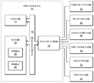
도 2는 본 발명의 실시예들에 사용되는 대표적인 컴퓨터 시스템의 대표적인 회로 기판 구성을 도시하는, 원래의 참조 번호가 보존된, 미국 특허 제7,075,784호의 도 3의 카피를 도시한다.
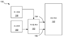
도 3은 본 발명의 실시예들에 사용되는 대표적인 컴퓨터 시스템을 도시한다.
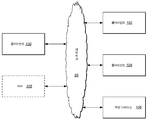
도 4는 본 발명의 실시예들에 사용되는 대표적인 네트워크 컴퓨터 시스템을 도시한다.
도 5는 다수의 플랫폼 관리 컨트롤러들 사이의 대표적인 연결들의 개략도를 도시한다.
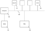
도 6은 컴퓨터 시스템 내의 대표적인 플랫폼 관리 컨트롤러와 다른 디바이스들 사이의 연결들의 개략도를 도시한다.
도 7은 본 발명의 일부 실시예들에 따른 트래킹 회로(tracking circuit)를 갖는 전자 시스템의 대표적인 블록도를 예시한다.
도 8은 본 발명의 일부 실시예들에 따른 트래킹 회로를 갖는 전자 시스템의 대표적인 블록도를 예시한다.
도 9는 본 발명의 일부 실시예들에 따른 트래킹 회로의 대표적인 블록도를 예시한다.
도 10은 본 발명의 일부 실시예들에 따른 트래킹 회로의 대표적인 블록도를 예시한다.
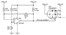
도 11은 본 발명의 일부 실시예들에 따른 트래킹 회로의 대표적인 개략도를 예시한다.
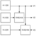
도 12는 본 발명의 일부 실시예들에 따른 트래킹 회로들의 대표적인 병렬 배치를 예시한다.
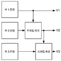
도 13은 본 발명의 일부 실시예들에 따른 트래킹 회로들의 대표적인 직렬 배치를 예시한다.
도 14는 생산 프로세스 동안의 대표적인 PCB의 평면도를 예시한다.
도 15는 생산 후의 대표적인 PCB의 평면도를 예시한다.
도 16은 본 발명의 실시예들에 의해 예상되는 대표적인 일시적 전기 연결 장치의 상단의 평면도를 예시한다.
도 17은 접착제를 갖는 일시적 전기 연결 장치의 다른 대표적인 실시예의 하측의 평면도를 예시한다.
도 18은 헤드(head)의 양 측면들 상에 로케이터(locator)들을 갖는 일시적 전기 연결 장치의 다른 대표적인 실시예의 하측의 평면도를 예시한다.
도 19는 로케이터들에 핀(pin)들을 갖는 도 18의 것과 유사한 대표적인 실시예의 정면도를 예시한다.
도 20은 로케이터들에 핀들을 갖고 이에 부착된 압축 피팅(compression fitting)을 갖는 도 18의 것과 유사한 대표적인 실시예의 정면도를 예시한다.
도 21은 대향하는 바이어스(bias)된 조우(jaw)들을 갖는 일시적 전기 연결 장치의 대표적인 실시예의 측면도를 예시한다.
도 22는 도 21의 대표적인 실시예의 정면도를 예시한다.
도 23은 PCB의 폭을 연계하여 분리한 두 개의 대향하는 고정 표면들을 갖는 일시적 전기 연결 장치 헤드의 다른 대표적인 실시예의 측면도를 예시한다.
도 24는 도 23의 대표적인 실시예의 정면도를 예시한다.The objects and features of the present invention will become more fully apparent from the following description and the appended claims, taken in conjunction with the accompanying drawings. BRIEF DESCRIPTION OF THE DRAWINGS The invention will be described and described in further detail and detail through the use of the accompanying drawings, with the understanding that these drawings show only typical embodiments of the invention and therefore should not be considered as limiting its scope.
1 shows a copy of FIG. 1 of US Pat. No. 7,075,784, with an original reference number preserved as an illustration of another exemplary computer system used in embodiments of the present invention.
FIG. 2 shows a copy of FIG. 3 of US Pat. No. 7,075,784, with the original reference numbers preserved, showing a representative circuit board configuration of an exemplary computer system used in embodiments of the present invention.
3 illustrates an exemplary computer system used in embodiments of the present invention.
4 illustrates an exemplary networked computer system used in embodiments of the present invention.
5 shows a schematic diagram of representative connections between multiple platform management controllers.
6 shows a schematic diagram of connections between a representative platform management controller and other devices in a computer system.
7 illustrates an exemplary block diagram of an electronic system having a tracking circuit in accordance with some embodiments of the present invention.
8 illustrates an exemplary block diagram of an electronic system having a tracking circuit in accordance with some embodiments of the present invention.
9 illustrates an exemplary block diagram of a tracking circuit in accordance with some embodiments of the present invention.
10 illustrates an exemplary block diagram of a tracking circuit in accordance with some embodiments of the present invention.
11 illustrates a representative schematic diagram of a tracking circuit in accordance with some embodiments of the present invention.
12 illustrates a representative parallel arrangement of tracking circuits in accordance with some embodiments of the present invention.
13 illustrates a representative series arrangement of tracking circuits in accordance with some embodiments of the present invention.
14 illustrates a top view of an exemplary PCB during the production process.
15 illustrates a top view of a representative PCB after production.
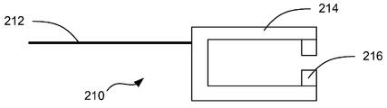
16 illustrates a plan view of the top of an exemplary temporary electrical connection device envisioned by embodiments of the present invention.
17 illustrates a top view of the underside of another representative embodiment of a temporary electrical connection device with adhesive.
18 illustrates a bottom plan view of another representative embodiment of a temporary electrical connection device with locators on both sides of the head.
19 illustrates a front view of a representative embodiment similar to that of FIG. 18 with pins on locators.
FIG. 20 illustrates a front view of a representative embodiment similar to that of FIG. 18 with pins on the locators and a compression fitting attached thereto.
21 illustrates a side view of a representative embodiment of a temporary electrical connection device with opposing biased jaws.
FIG. 22 illustrates a front view of the exemplary embodiment of FIG. 21.
FIG. 23 illustrates a side view of another representative embodiment of a temporary electrical connector head having two opposing fixed surfaces separated in conjunction with the width of the PCB.
FIG. 24 illustrates a front view of the exemplary embodiment of FIG. 23.
본 발명의 실시예들의 설명은 도면들을 참조하면서 아래에서 주어질 것이다. 본 발명은 많은 다른 형태들 및 형상들을 취할 수 있고, 따라서 다음 발명은 예시적이며 제한이 아닌 것으로 의도되고, 본 발명의 범위는 첨부된 청구항들을 참조함으로써 결정되어야 하는 것이 기대된다.Description of the embodiments of the present invention will be given below with reference to the drawings. The invention can take many different forms and shapes, and therefore the following invention is intended to be illustrative and not restrictive, and it is anticipated that the scope of the invention should be determined by reference to the appended claims.
본 발명의 실시예들은 컴퓨터 시스템들 및 컴퓨터 시스템 동작의 다양한 측면들의 지능형 유연 관리 및 감시를 위한 시스템들 및 방법들을 제공한다. 본 발명의 실시예들은 다양한 범용 컴퓨터 시스템들 및 다양한 특수 용도 컴퓨터 시스템들을 포함하는, 다양한 기존 및 장래의 컴퓨터 시스템들에 적용가능하다. 본 발명이 다양한 방법들로 구현될 수 있는 컴퓨터 시스템의 하나의 분류 또는 구성은 발명의 명칭이 Non-Peripherals Processing Control Module Having Improved Heat Dissipating Properties인 미국 특허 제7,256,991호, 발명의 명칭이 Robust Customizable Computer Processing System인 제7,242,574호, 및 발명의 명칭이 Systems and Methods for Providing a Dynamically Modular Processing Unit인 제7,075,784호에 개시되어 있으며, 그들은 모든 발명을 위해 본 출원에 참고문헌으로 명백히 통합되어 있다.Embodiments of the present invention provide systems and methods for intelligent flexible management and monitoring of computer systems and various aspects of computer system operation. Embodiments of the present invention are applicable to a variety of existing and future computer systems, including various general purpose computer systems and various special purpose computer systems. One classification or configuration of a computer system in which the present invention may be implemented in various ways is described in US Pat. No. 7,256,991, entitled Non-Peripherals Processing Control Module Having Improved Heat Dissipating Properties, entitled Robust Customizable Computer Processing. System 7,242,574, and the name of the invention are disclosed in Systems and Methods for Providing a Dynamically Modular Processing Unit, 7,75,784, which are expressly incorporated herein by reference for all inventions.
상기 참조된 특허들에 개시된 것과 같은 복수의 상호 접속 회로 기판들을 갖고 사용하도록 구성된 컴퓨터 시스템에서, 본 발명의 어떤 실시예들은 인증된 회로 기판들만이 컴퓨터 시스템에 사용되는 것을 보증하기 위한 시스템을 제공한다. 시스템은 각각의 회로 기판들 상에 위치된 인증 칩(chip)을 포함한다. 각 인증 칩은 1) 기능을 위한 컴퓨터 및 기능을 위한 인증 칩이 위치되는 회로 기판 중 하나에 필요한 핵심 기능 및 2) 컴퓨터 시스템에서 적절히 기능하기 위해 회로 기판이 테스트되어 인증된 것을 전달하는 인증 기능을 포함한다. 또한, 시스템은 시스템에 통합된 각 회로 기판의 인증된 상태를 검증하기 위해 각각의 인증 칩들이 서로 통신하는 것을 가능하게 하는 인증 통신들 버스를 포함한다. 적어도 일부 그러한 시스템들에 있어서, 인증 칩이 없는 회로 기판이 컴퓨터 시스템에 부착되면 각 인증 칩은 컴퓨터 시스템이 기능하는 것을 방지하도록 구성된다.In a computer system configured for use with a plurality of interconnect circuit boards as disclosed in the above referenced patents, certain embodiments of the present invention provide a system for ensuring that only certified circuit boards are used in a computer system. . The system includes an authentication chip located on respective circuit boards. Each authentication chip has 1) a key function required for one of the circuit boards on which the computer for the function and the authentication chip for the function are located, and 2) an authentication function that conveys that the circuit board has been tested and certified for proper functioning in the computer system. Include. The system also includes a bus of authentication communications that enable each authentication chip to communicate with each other to verify the authenticated state of each circuit board integrated into the system. In at least some such systems, each authentication chip is configured to prevent the computer system from functioning if a circuit board without an authentication chip is attached to the computer system.
어떤 실시예들에 있어서, 각 인증 칩은 그의 각 회로 기판상에서 조건들을 감시하도록 구성된다. 인증 칩들은 회로 기판들 상에서 감시된 조건들의 기록을 유지할 수 있고, 각 인증 칩은 그의 각 회로 기판상에서 조건들의 보고들을 송신하도록 구성될 수 있다.In some embodiments, each authentication chip is configured to monitor conditions on its respective circuit board. The authentication chips may maintain a record of conditions monitored on the circuit boards, and each authentication chip may be configured to transmit reports of conditions on its respective circuit board.
각 인증 칩이 컴퓨터 시스템에 대한 전력 제어에 지능적으로 관여하도록 구성되는 일부 실시예들에 있어서, 인증 칩들은 컴퓨터 시스템에 대한 복수의 전원들을 턴 온 및 오프하는 타이밍에 협력적으로 관여한다. 일부 그러한 실시예들에 있어서, 인증 칩들은 컴퓨터의 전원들을 칩 안전 순서로 순차적으로 턴 온함으로써 및 순차적인 순서로 이전의 모든 전원들이 적절히 턴 온된 것을 검증한 후에만 컴퓨터 시스템의 칩들을 파괴할 위험이 있는 것으로 알려져 있는 컴퓨터 시스템 내의 전력 조건들의 존재를 공동으로 방지한다. 추가적으로 또는 대안적으로, 인증 칩들은 컴퓨터 시스템 내의 전원 고장의 검출시에 방치되면 칩들에 손상을 초래할 수 있는 전원들을 신속히 턴 오프함으로써 컴퓨터 시스템의 칩들을 파괴할 위험이 있는 것으로 알려져 있는 컴퓨터 시스템 내의 전력 조건들의 존재를 공동으로 방지한다.In some embodiments, where each authentication chip is configured to intelligently participate in power control for a computer system, the authentication chips cooperatively participate in the timing of turning on and off a plurality of power sources for the computer system. In some such embodiments, the authentication chips risk destroying the chips of the computer system only by sequentially turning on the power supplies of the computer in chip safety order and after verifying that all previous power supplies are properly turned on in the sequential order. Jointly prevent the presence of power conditions in a computer system that are known to be present. Additionally or alternatively, power chips in a computer system that are known to be at risk of destroying chips in a computer system by quickly turning off power supplies that can damage the chips if left undetected upon detection of a power failure in the computer system. Jointly prevent the presence of conditions.
적어도 일부 실시예들에 있어서, 인증 칩들은 전력 제어를 감시하고 전원들의 활성화 및 비활성화를 제어하도록 구성된 로직 게이트(logic chip)들을 포함하며, 그것에 의해 전원의 고장시 다른 전원들의 비활성화는 컴퓨터 시스템에 대한 손상을 방지하기 위해 충분히 신속해진다. 적어도 일부 실시예들에 있어서, 다른 전원들의 비활성화는 수개 내지 소수의 클록 사이클(clock cycle)들 내에서 발생한다.In at least some embodiments, the authentication chips include logic gates configured to monitor power control and control activation and deactivation of the power sources, whereby deactivation of other power sources in the event of a power failure is caused by the computer system. Becomes fast enough to prevent damage. In at least some embodiments, deactivation of other power supplies occurs within several to few clock cycles.
구현된 바와 같이, 컴퓨터 시스템이 턴 오프될지라도, 인증 칩들은 컴퓨터 시스템이 전원에 연결되어 있는 언제라도 동작할 수 있다. 인증 칩들은 컴퓨터 시스템들의 측파대(sideband) 관리를 수행하고, 로직 게이트들만을 사용하여 그렇게 행할 수 있다.As implemented, even when the computer system is turned off, the authentication chips can operate any time the computer system is connected to a power source. The authentication chips perform sideband management of computer systems and can do so using only logic gates.
어떤 실시예들에 있어서, 고장 이벤트들이 인증 칩들 내의 로직 게이트들에 의해 검출되어 기록되고, 그 후에 인증 칩들은 고장 이벤트들을 협력적으로 로그하고 컴퓨터 시스템을 셧 다운(shut down)하도록 구성된다. 인증 칩들은 다음 파워 온(power-on) 시도 중 하나 이상에, 및 고장시 언제라도 고장 이벤트들의 기록을 송신하도록 구성될 수 있다.In some embodiments, fault events are detected and recorded by logic gates in the authentication chips, after which the authentication chips are configured to cooperatively log the failure events and shut down the computer system. The authentication chips may be configured to transmit a record of fault events at one or more of the next power-on attempts, and at any time upon failure.
일부 실시예들에 있어서, 컴퓨터 시스템이 실행되고 있을 때, 인증 칩들은 내부 집적 회로(I2C: inter-integrated circuit) 버스, 및 낮은 핀 카운트(LPC: low pin count) 버스와 같은, 컴퓨터 시스템의 하나 이상의 버스들 상에 발생하는 통신들을 스누프(snoop)하도록 구성된다. 인증 칩들은 입력/출력(I/O: input/output) 통신들 및 포스트 코드들과 같은, 스누프된 통신들에 응답하도록 구성될 수 있다.In some embodiments, when the computer system is running, the authentication chips are a computer system, such as an inter-integrated circuit (I 2 C) bus, and a low pin count (LPC) bus. And to snoop communications occurring on one or more buses of the network. Authentication chips may be configured to respond to snooped communications, such as input / output (I / O) communications and post codes.
본 발명의 실시예들에 있어서, 하나 이상의 인증 칩들은 로직 게이트들을 사용하여 실시간 프로세서 에뮬레이션을 제공하도록 구성된다. 실시간 프로세서 에뮬레이션을 제공하는 하나 이상의 인증 칩들은 선택된 입력들을 위해 특정하게 선택된 출력들을 자동으로 및 신속히 제공할 수 있다. 어떤 경우들에서, 하나 이상의 인증 칩들은 PS/2 키보드 컨트롤러 및 비디오 컨트롤러 중 하나에 에뮬레이션을 제공한다.In embodiments of the present invention, one or more authentication chips are configured to provide real time processor emulation using logic gates. One or more authentication chips that provide real-time processor emulation can automatically and quickly provide specifically selected outputs for selected inputs. In some cases, one or more authentication chips provide emulation to one of a PS / 2 keyboard controller and a video controller.
어떤 실시예들에 있어서, 인증 칩들은 전원이 초기에 컴퓨터 시스템에 연결될 때, 컴퓨터 시스템이 턴 온되어 사용되는 것을 가능하게 하기 전에 각각이 활성화되어 기능할 준비가 되는 것을 보증하기 위해 인증 칩들이 서로에 통신들을 제공하도록 구성된다.In some embodiments, the authentication chips are authenticated chips to each other to ensure that when the power source is initially connected to the computer system, each of the authentication chips are activated and ready to function before enabling the computer system to be turned on and used. To provide communications.
어떤 실시예들은 컴퓨터 시스템에서 나타나고, 여기서 컴퓨터 시스템의 통합된 측파대 관리를 제공하기 위한 시스템은 컴퓨터 시스템에 통합되고 로직 게이트들만을 사용하여 컴퓨터 시스템의 측파대 관리를 제공하는 측파대 관리 디바이스를 사용하여 제공된다. 측파대 관리 디바이스는 파워 업(power-up) 시 컴퓨터 시스템의 전원들의 활성화의 적절한 시퀀싱을 보증하는 파워 온 관리를 제공할 수 있다. 측파대 관리 디바이스는 부적절하고, 잠재적으로 손상되는, 전압 조합들이 컴퓨터 시스템에서 발생하는 것을 방지하는 방법으로 전원들의 활성화만이 발생하는 것을 보증할 수 있다. 측파대 관리 디바이스는 전원 시퀀싱을 중단하고, 컴퓨터 시스템을 턴 오프하며, 하나 이상의 전원들이 활성화되지 않을 때 결함 상태의 상세를 로그(log)하도록 구성될 수 있다.Some embodiments appear in a computer system, where a system for providing integrated sideband management of the computer system uses a sideband management device that is integrated into the computer system and provides sideband management of the computer system using only logic gates. Is provided. The sideband management device may provide power-on management that ensures proper sequencing of activation of the power sources of the computer system upon power-up. The sideband management device can ensure that only activation of power sources occurs in a way that prevents inappropriate, potentially damaging, voltage combinations from occurring in a computer system. The sideband management device may be configured to stop power sequencing, turn off the computer system, and log details of a fault condition when one or more power supplies are not active.
어떤 실시예들의 측파대 관리 디바이스는 컴퓨터 시스템의 다중 회로 기판들에 걸쳐서 분배된 복수의 디바이스들을 포함할 수 있다. 그럼에도 불구하고, 컴퓨터 시스템이 턴 오프될 때 측파대 관리 디바이스는 전원 공급된 채로 남아 있을 수 있다. 어떤 실시예들에 있어서, 컴퓨터 시스템은 단일 컴퓨터 디바이스이고 측파대 관리 디바이스는 컴퓨터 디바이스의 적어도 하나의 회로 기판에 통합되며, 그것에 의해 측파대 관리 디바이스는 개별 프로세서 또는 컴퓨터 디바이스를 포함하지 않는다.The sideband management device of some embodiments may include a plurality of devices distributed across multiple circuit boards of a computer system. Nevertheless, the sideband management device may remain powered on when the computer system is turned off. In some embodiments, the computer system is a single computer device and the sideband management device is integrated into at least one circuit board of the computer device whereby the sideband management device does not include a separate processor or computer device.
본 발명의 실시예들은 컴퓨터 시스템의 기능에 필요한 상이한 전압들의 복수의 전원들을 포함하는 컴퓨터 시스템에서 전원들의 활성화를 제어하기 위한 방법을 제공한다. 방법은 복수의 전원들 중 하나 이상의 활성화를 선택적으로 지시하는 단계 및 활성화되도록 지시된 전원들이 적절히 턴 온되는지를 감시하는 단계를 포함한다. 활성화되도록 지시된 전원들 중 하나 이상이 설정 시간 내에 적절히 턴 온되지 않을 때, 방법은 고장 이벤트를 로그하는 것 및 컴퓨터 시스템을 턴 오프하는 단계를 포함한다.Embodiments of the present invention provide a method for controlling activation of power supplies in a computer system that includes a plurality of power supplies of different voltages required for the functionality of the computer system. The method includes selectively instructing activation of one or more of the plurality of power supplies and monitoring whether the power supplies indicated to be activated are properly turned on. When one or more of the power sources instructed to be activated are not properly turned on within a set time, the method includes logging a failure event and turning off the computer system.
방법의 일부 실시예들에 있어서, 전원들은 부적절한 전압 시퀀스들에 의해 초래되는 컴퓨터 시스템의 구성요소들에 대한 손상을 방지하도록 설계된 시퀀스에서 활성화되고, 각 전원의 활성화는 활성화의 시퀀스가 연속되기 전에 적절한 활성화를 위해 감시된다. 적어도 일부 실시예들에 있어서, 컴퓨터 시스템을 턴 오프하는 단계는 부적절한 전압 시퀀스들에 의해 초래되는 컴퓨터 시스템의 구성요소들에 대한 손상을 방지하는 순서로 실행가능해지는 임의의 전원들을 비활성화하는 단계를 포함한다.In some embodiments of the method, the power supplies are activated in a sequence designed to prevent damage to the components of the computer system caused by inappropriate voltage sequences, and activation of each power supply is appropriate before the sequence of activation is continued. Monitored for activation. In at least some embodiments, turning off the computer system includes deactivating any power supplies that become executable in an order that prevents damage to the components of the computer system caused by inappropriate voltage sequences. do.
본 발명의 실시예들은 복수의 회로 기판들을 갖는 컴퓨터 시스템을 위해 전력 관리 시스템을 제공한다. 전력 관리 시스템은 컴퓨터 시스템의 회로 기판들에 걸쳐서 확장되는 전력 관리 버스 및 전력 관리 버스에 통신적으로 결합된 복수의 플랫폼 관리 컨트롤러들(PMCs: platform management controllers)을 포함하며, 여기서 각 PMC는 상이한 회로 기판상에 위치되고, 그의 각 회로 기판상에서 전원들을 제어하도록 구성된다.Embodiments of the present invention provide a power management system for a computer system having a plurality of circuit boards. The power management system includes a power management bus that extends across circuit boards of the computer system and a plurality of platform management controllers (PMCs) communicatively coupled to the power management bus, where each PMC is a different circuit. Located on the substrate and configured to control the power supplies on each circuit board thereof.
적어도 일부 실시예들에 있어서, 각 PMC는 전적으로 로직 게이트들로 구현된다. PMC들은 컴퓨터가 턴 온되는지에 관계없이, 컴퓨터 시스템이 입력 전원에 연결되는 언제라도 동작하도록 구성될 수 있다. 또한, PMC들은 컴퓨터 시스템의 임의의 전원들이 활성화되는 것을 가능하게 하기 전에 다른 PMC들이 활성화되는 것을 보증하도록 구성될 수 있다. PMC들은 전력 관리 버스를 사용하여 다른 컨트롤러들이 활성화될 때 수신되는 바와 같이 다른 컨트롤러들에 통과되어 다른 컨트롤러들에 의해 전달되는 컨트롤러 특정 키(key)들을 발생시킴으로써 다른 PMC들이 활성화되는 것을 결정할 수 있으며, 그것에 의해 각 컨트롤러가 그 자체의 키를 다시 수신할 때 그것은 모든 컨트롤러들이 활성화되는 것을 인식한다.In at least some embodiments, each PMC is implemented entirely with logic gates. The PMCs can be configured to operate any time the computer system is connected to an input power source, regardless of whether the computer is turned on. In addition, the PMCs may be configured to ensure that other PMCs are activated before allowing any power sources of the computer system to be activated. The PMCs can use the power management bus to determine which other PMCs are active by generating controller specific keys that are passed through and passed by the other controllers, as received when other controllers are activated. Thereby when each controller receives its own key again it recognizes that all controllers are active.
본 발명의 실시예들은 컴퓨터 시스템의 속도를 개선하면서 컴퓨터 시스템 내의 프로세서 기반 컴퓨터 구성요소를 에뮬레이션하기 위한 시스템을 제공한다. 프로세서 기반 컴퓨터 구성요소를 에뮬레이션하기 위한 시스템은 로직 게이트들만을 사용하여 프로세서 기반 컴퓨터 구성요소를 에뮬레이션하도록 구성된 로직 게이트 기반 디바이스를 포함하며, 여기서 로직 게이트들은 프로세서 기반 컴퓨터 구성요소에 의해 통상 취급되는 명령들의 세트를 수신하고 단지 훨씬 더 빠른 속도로 프로세서 기반 컴퓨터 구성요소에 의해 통상 출력되는 출력을 제공하도록 구성된다. 일부 실시예들에 있어서, 로직 게이트들은 프로세서 기반 컴퓨터 구성요소에 의해 통상 취급되는 모든 가능한 명령들의 서브세트만을 인지하고 응답하도록 구성된다. 로직 게이트 기반 디바이스는 컴퓨터 시스템에 의해 활성적으로 사용되지 않는 레거시(legacy) 컴퓨터 디바이스의 에뮬레이션을 제공할 수 있지만, 그의 존재는 1) 컴퓨터 시스템의 기본 입력/출력 시스템(BIOS: basic input/output system) 및 2) 컴퓨터 시스템의 운영 체제(OS: operating system) 중 하나의 적절한 동작에 요구된다.Embodiments of the present invention provide a system for emulating processor-based computer components within a computer system while improving the speed of the computer system. A system for emulating a processor-based computer component includes a logic gate-based device configured to emulate a processor-based computer component using only logic gates, where the logic gates are configured of instructions typically handled by the processor-based computer component. It is configured to receive the set and provide the output normally output by the processor-based computer component at a much faster rate. In some embodiments, the logic gates are configured to recognize and respond to only a subset of all possible instructions typically handled by the processor-based computer component. Logic gate-based devices can provide emulation of legacy computer devices that are not actively used by the computer system, but their presence includes: 1) basic input / output system (BIOS) of the computer system. And 2) proper operation of one of the operating systems (OSs) of the computer system.
본 발명의 어떤 실시예들은 디지털 통신들을 인코딩(encoding), 송신, 및 디코딩(decoding)하기 위한 방법을 제공하며, 여기서 통신의 데이터 부분들은 본래 추가 데이터 비트(bit)들을 필요로 하지 않고 수신된 데이터 부분들의 유효성에 관한 체크섬(checksum) 정보를 포함한다. 방법은 디지털 데이터의 어떤 패턴(pattern)들이 무효인 방식을 사용하여 정보를 디지털 스트림(digital stream)으로 인코딩하는 단계 및 송신기를 반복적으로 사용하여 디지털 스트림을 송신하는 단계를 포함한다. 수신기는 수신된 정보를 수신하고, 수신된 정보는 유효 및 무효 패턴들에 대해 평가된다. 유효 개시 패턴 다음에 하나 이상의 유효 데이터 패턴들이 뒤따를 때, 수신된 정보는 단지 유지되고 디코딩된다.Certain embodiments of the present invention provide a method for encoding, transmitting, and decoding digital communications, wherein the data portions of the communication inherently received data without requiring additional data bits. Contains checksum information about the validity of the parts. The method includes encoding information into a digital stream using a manner in which certain patterns of digital data are invalid, and transmitting the digital stream repeatedly using a transmitter. The receiver receives the received information, and the received information is evaluated for valid and invalid patterns. When one or more valid data patterns follow a valid start pattern, the received information is only maintained and decoded.
개시 패턴은 데이터 스트림에 포함되는 데이터의 유형에 관한 정보를 포함할 수 있다. 또한, 개시 패턴은 디지털 스트림이 반복된 횟수에 관한 정보를 포함할 수 있다.The disclosure pattern may include information regarding the type of data included in the data stream. In addition, the start pattern may include information about the number of times the digital stream is repeated.
본 발명의 실시예들은 컴퓨터 시스템에 통합된 PMC를 사용하여 컴퓨터 시스템의 시동 및 기능을 감시하기 위한 방법을 제공한다. 방법은 컴퓨터 시스템에 PMC를 제공하는 단계를 포함하며, 여기서 PMC는 컴퓨터 시스템의 전력을 관리하고 컴퓨터 시스템의 기능에 관한 정보를 컴퓨터 시스템으로부터 획득할 수 있도록 컴퓨터 시스템에 연결되고, 여기서 PMC는 송신기에 동작적으로 연결된다. 또한, 방법은 컴퓨터 시스템의 시동 및 동작을 감시하기 위해 PMC를 사용하는 단계, 컴퓨터 시스템의 시동 및 동작 중 적어도 하나에 관한 이벤트들에 로그하기 위해 PMC를 사용하는 단계, 및 송신기를 사용하여 로그된 이벤트들을 송신하기 위해 PMC를 사용하는 단계를 포함한다.Embodiments of the present invention provide a method for monitoring the startup and functioning of a computer system using a PMC integrated into the computer system. The method includes providing a PMC to a computer system, where the PMC is coupled to the computer system to manage power of the computer system and obtain information about the computer system's functionality from the computer system, where the PMC is connected to the transmitter. It is operatively connected. The method also includes using the PMC to monitor startup and operation of the computer system, using the PMC to log events relating to at least one of the startup and operation of the computer system, and logging using the transmitter. Using the PMC to transmit events.
로그된 이벤트들은 시동시 컴퓨터 시스템에 의해 발생된 포스트 코드들을 포함할 수 있다. 로그된 이벤트들이 포스트 코드들을 포함할 때, PMC는 시동시 언제라도 포스트 코드들을 송신할 수 있다. 로그된 이벤트들은 셧다운(shutdown) 시간 및 검출된 비정상 온도의 시간 중 하나에서 컴퓨터 시스템으로부터 획득된 온도 판독을 추가적으로 또는 대안적으로 포함할 수 있다. 일부 실시예들에 있어서, 컴퓨터 시스템의 운영 체제는 외부 송신을 위해 PMC에 메시지(message)들을 전송하도록 구성된다.The logged events may include post codes generated by the computer system at startup. When logged events include post codes, the PMC may send post codes at any time upon startup. The logged events may additionally or alternatively include a temperature reading obtained from the computer system at one of a shutdown time and a time of detected abnormal temperature. In some embodiments, the operating system of the computer system is configured to send messages to the PMC for external transmission.
본 발명의 실시예들은 전원 트래킹 장치를 제공하기 위한 기술에 관한 것이다. 특히, 본 발명의 적어도 일부 실시예들은 연산 회로의 제 1 전력 입력이 연산 회로의 제 2 전력 입력에 대해 미리 정의된 관계를 유지하는 것을 보증하기 위한 전원 트래킹 장치에 관한 것이다.Embodiments of the present invention relate to a technique for providing a power tracking device. In particular, at least some embodiments of the present invention relate to a power tracking device for ensuring that a first power input of a computing circuit maintains a predefined relationship to a second power input of a computing circuit.
본 발명의 실시예들은 기준 전압원, 비교기, 및 스위치(switch)를 갖는 전원 트래킹 장치를 포함한다. 기준 전압원은 기준 전압을 비교기의 제 1 입력에 제공한다. 비교기의 제 2 입력은 제 1 전력 입력에 결합된다. 비교기의 출력은 기준 전압 및 제 1 전력 입력의 상대 전압의 함수로서 상태를 스위칭한다. 비교기의 출력은 스위치를 제어하고, 따라서 기준 전압 및 제 1 전력 입력의 상대 전압에 따라 스위치를 개방 및 폐쇄한다. 스위치는 전원과 제 2 전력 입력 사이에 배치된다. 따라서, 제 2 전력 입력은 제 1 전력 입력에 대한 미리 정의된 관계로 유지될 수 있다.Embodiments of the present invention include a power supply tracking device having a reference voltage source, a comparator, and a switch. The reference voltage source provides a reference voltage to the first input of the comparator. The second input of the comparator is coupled to the first power input. The output of the comparator switches state as a function of the reference voltage and the relative voltage of the first power input. The output of the comparator controls the switch, thus opening and closing the switch in accordance with the reference voltage and the relative voltage of the first power input. The switch is disposed between the power source and the second power input. Thus, the second power input can be maintained in a predefined relationship to the first power input.
본 발명의 실시예들의 방법들 및 프로세스들은 개인용 컴퓨팅 엔터프라이즈들의 영역에 특히 유용한 것으로 증명되었을지라도, 당업자들은 제어 시스템들 또는 스마트 인터페이스 시스템(smart-interface system)들을 사용하는 임의의 산업에 대한 엔터프라이즈들 및/또는 그러한 디바이스들의 실시예들로부터 이득을 얻는 엔터프라이즈들을 포함하는 커스터마이즈(customize) 가능 엔터프라이즈들을 산출하기 위해 본 발명의 방법들 및 프로세스들이 각종 상이한 애플리케이션들 및 각종 상이한 제조 영역들에 사용될 수 있다는 것을 인식할 것이다. 그러한 산업들의 예들은 자동차 산업들, 항공 전자 산업들, 유압 제어 산업들, 오토/비디오 제어 산업들, 전기통신 산업들, 의료 산업들, 특수 용도 산업들, 및 가전 기기 산업들을 포함하지만, 이들에 제한되지 않는다. 따라서, 본 발명의 시스템들 및 방법들은 현재 컴퓨터 기술에 의해 종래에 이용되지 않았던 마켓(market)들을 포함하는 많은 상이한 마켓들에 이점들을 제공할 수 있다.Although the methods and processes of embodiments of the present invention have proved to be particularly useful in the area of personal computing enterprises, those skilled in the art will appreciate that any enterprise for any industry using control systems or smart-interface systems and Recognize that the methods and processes of the present invention can be used in a variety of different applications and in a variety of different manufacturing areas to produce customizable enterprises including those that benefit from embodiments of such devices. something to do. Examples of such industries include, but are not limited to, automotive industries, avionics, hydraulic control industries, auto / video control industries, telecommunications industries, medical industries, special purpose industries, and consumer electronics industries. It is not limited. Thus, the systems and methods of the present invention may provide advantages to many different markets, including markets that have not previously been used by current computer technology.
본 발명의 실시예들은 컴퓨터 시스템들 진단 정보를 무선으로 수신하고 그러한 정보를 커스터마이즈 가능하게 표시하기 위한 시스템들 및 방법들을 제공한다. 정보는 다양한 범용 컴퓨터 시스템들 및 다양한 특수 용도 컴퓨터 시스템들을 포함하는, 다양한 기존 및 장래의 컴퓨터 시스템들로부터 수신될 수 있다. 본 출원에 개시된 바와 같이, 컴퓨터 시스템에 통합된 플랫폼 관리 컨트롤러(PMC) 또는 유사한 디바이스는 컴퓨터 시스템 정보를 감시하고 감시된 정보를, 예컨대 적외선에 의해 송신하거나 그 외 전달한다. 본 발명의 실시예들은 송신된 정보를 수신하므로, 그것은 본 출원에 개시된 것과 같은 다양한 목적들에 이용될 수 있다.Embodiments of the present invention provide systems and methods for wirelessly receiving computer systems diagnostic information and customizing the display of such information. Information may be received from a variety of existing and future computer systems, including various general purpose computer systems and various special purpose computer systems. As disclosed herein, a Platform Management Controller (PMC) or similar device integrated into a computer system monitors computer system information and transmits or otherwise transmits the monitored information, such as by infrared light. Since embodiments of the present invention receive the transmitted information, it can be used for various purposes as disclosed in this application.
본 발명의 실시예들에 있어서, PMC 또는 다른 유사한 디바이스에 의해 송신된 복수의 로그된 이벤트들은 무선 진단 디바이스와 같은 진단 디바이스에 의해 수신 및 감시될 수 있다. 본 발명의 적어도 일부 실시예들에 있어서, 진단 디바이스의 처리 특징들은 주로 또는 전적으로 로직 게이트들로 구현된다. 그러한 실시예들은 본 출원에서 더 상세히 논의되는 어떤 장점들을 제공한다. 본 출원에서 논의되는 진단 디바이스들의 어떤 실시예들은 로직 게이트 디바이스들을 사용하여 구현될지라도, 진단 디바이스들은 이 기술분야에 현재 공지되어 있거나 장래에 발명될 유형들의 각종 다른 컴퓨터 시스템들에 정보를 제공하거나 정보를 전달한다는 것이 인식될 것이다. 예를 들어, 적어도 일부 실시예들에 있어서, 진단 디바이스는 범용 직렬 버스(USB: universal serial bus) 연결, 이더넷(Ethernet) 연결 등과 같은, 유선 또는 무선 연결을 사용하여 외부 컴퓨터 시스템에 연결될 수 있다. 그러한 연결은 통신들이 PMC 또는 다른 유사한 디바이스로부터 수신되는 시간, 또는 어느 나중의 시간을 포함하는, 진단 디바이스의 사용 동안 언제든지 이루어질 수 있다. 그러므로, 이하의 논의는 어떤 이유로 진단 디바이스와 함께 사용되거나 진단 디바이스에 연결될 수 있는 컴퓨터 시스템들을 설명하도록 의도된다.In embodiments of the present invention, a plurality of logged events sent by a PMC or other similar device may be received and monitored by a diagnostic device, such as a wireless diagnostic device. In at least some embodiments of the invention, the processing features of the diagnostic device are mainly or wholly implemented with logic gates. Such embodiments provide certain advantages discussed in more detail in this application. Although some embodiments of the diagnostic devices discussed in this application may be implemented using logic gate devices, the diagnostic devices may provide or provide information to various other computer systems of the types currently known in the art or to be invented in the future. Will be appreciated. For example, in at least some embodiments, the diagnostic device may be connected to an external computer system using a wired or wireless connection, such as a universal serial bus (USB) connection, an Ethernet connection, and the like. Such a connection may be made at any time during use of the diagnostic device, including the time at which communications are received from the PMC or other similar device, or any later time. Therefore, the following discussion is intended to describe computer systems that may be used with or connected to the diagnostic device for some reason.
본 발명의 실시예들은 일시적 전기 연결들에 관한 것이다. 특히, 본 발명은 인쇄 회로 기판(PCB)로부터 또는 PCB에 정보를 수신 또는 송신하기 위해 외부 디바이스를 PCB에 일시적으로 연결하기 위한 시스템들 및 방법들에 관한 것이다.Embodiments of the present invention relate to transient electrical connections. In particular, the present invention relates to systems and methods for temporarily connecting an external device to a PCB for receiving or transmitting information to or from a printed circuit board (PCB).
본 발명의 실시예들은 연결을 통해서 데이터의 전송을 용이하게 하기 위한 외부 소스와 PCB 사이의 일시적 전기 연결들과 관련하여 실시된다. 적어도 하나의 실시예들에 있어서, 일시적 전기 시스템은 PCB의 하나 이상의 에지(edge)들에 인접하여 배치된 전기 접촉 패드들을 갖는 PCB를 포함한다. 전기 접촉 패드들은 차례로 PCB 상의 특정 위치들에 전기적으로 연결된다. 시스템들은 전선 리본(electrical wire ribbon) 및 PCB의 에지(들) 상에 배치된 전기 패드들에 대응하는 하나 이상의 전기 접촉 패드들이 배치된 전선 리본의 원위 단부의 헤드(head)를 차례로 포함하는 일시적 전기 커넥터 장치를 더 포함한다.Embodiments of the present invention are practiced in connection with transient electrical connections between an external source and a PCB to facilitate the transfer of data through the connection. In at least one embodiment, the temporary electrical system includes a PCB having electrical contact pads disposed adjacent one or more edges of the PCB. The electrical contact pads are in turn electrically connected to specific locations on the PCB. The systems in turn comprise an electrical wire ribbon and a temporary electrical head that in turn comprises a head of the distal end of the wire ribbon with one or more electrical contact pads corresponding to the electrical pads disposed on the edge (s) of the PCB. It further comprises a connector device.
추가 실시예들에 있어서, PCB와 일시적으로 전기적으로 연결되도록 적응된 장치는 전선 리본을 포함한다. 장치는 하나 이상의 전기 접촉 패드들이 배치된 전선 리본의 원위 단부에 헤드를 더 포함한다. 또한, 일부 실시예들에 있어서, 헤드는 그 위에 배치된 접착제를 가지며, 이는 전기 접촉 패드들을 실질적으로 둘러싼다. 사용 전에, 접착제는 사용 시에 제거될 수 있는 논-스틱 페이퍼 백킹(non-stick paper backing) 등에 의해 보호된다. 다른 실시예들에 있어서, 헤드는 헤드를 팽팽하게 하도록 조작될 수 있는 압축 피팅(compression fitting)을 포함하여, 그것은 PCB와 같은 대응하는 표면에 고정된 채로 일시적으로 남아 있는다. 또 다른 실시예들에 있어서, 헤드는 헤드 및 PCB와 같은 대응하는 표면 사이에서 일시적 연결을 용이하게 하는데 사용될 수 있는 핀(pin)들 또는 다른 로케이터들을 포함한다. 더 다른 실시예들에 있어서, 헤드는 조우(jaw)들을 폐쇄된 위치에서 바이어스(bias)하는 동작 스프링(spring)에 의해 연결된 두 개의 대향하는 조우들로 구성되어, 조우들은 사용자에 의해 선택적으로 개방될 수 있고 헤드는 PCB와 같은 대응하는 표면에 일시적으로 "클립(clip)"된다. 또 다른 실시예들에 있어서, 헤드는 PCB의 폭을 연계하여 분리한 두 개의 대향하는 고정 표면들로 구성되어, 헤드는 이에 일시적으로 고정된 채로 남아 있기 위해 PCB의 에지에 걸쳐서 일시적으로 슬립(slip)될 수 있다.In further embodiments, a device adapted to temporarily electrically connect with a PCB includes a wire ribbon. The apparatus further includes a head at the distal end of the wire ribbon on which one or more electrical contact pads are disposed. In addition, in some embodiments, the head has an adhesive disposed thereon, which substantially surrounds the electrical contact pads. Prior to use, the adhesive is protected by non-stick paper backing or the like that can be removed during use. In other embodiments, the head includes a compression fitting that can be manipulated to tighten the head so that it temporarily remains fixed to a corresponding surface, such as a PCB. In still other embodiments, the head includes pins or other locators that can be used to facilitate a temporary connection between the head and the corresponding surface, such as a PCB. In still other embodiments, the head consists of two opposing jaws connected by an actuating spring that biases the jaws in a closed position such that the jaws are selectively opened by the user. And the head is temporarily "clipped" to the corresponding surface, such as a PCB. In still other embodiments, the head consists of two opposing fixed surfaces separated in conjunction with the width of the PCB so that the head temporarily slips across the edge of the PCB to remain temporarily fixed thereto. Can be
본 발명의 실시예들의 방법들 및 프로세스들은 일시적 PCB 연결들의 영역에 특히 유용한 것으로 증명되었을지라도, 당업자들은 일시적이고, 편리하며 저렴한 전기 연결들을 산출하기 위해 방법들 및 프로세스들이 각종 상이한 애플리케이션들 및 각종 상이한 제조 영역들에 사용될 수 있다는 것을 인식할 수 있다.Although the methods and processes of embodiments of the present invention have proved to be particularly useful in the area of temporary PCB connections, those skilled in the art will appreciate that the methods and processes may be modified in various different applications and in a variety of different applications to yield temporary, convenient and inexpensive electrical connections. It can be appreciated that it can be used in manufacturing areas.
본 발명의 실시예들의 측면들은 논의 및 명료성을 위해 다양한 표제들을 사용하여 논의될 것이다. 표제들은 예시된 실시예들의 측면들을 용이하게 하는 것으로만 제공되고, 어떤 방식을 제한하는 것으로 의도되지 않는다.Aspects of embodiments of the invention will be discussed using various headings for discussion and clarity. Headings are provided only to facilitate aspects of the illustrated embodiments, and are not intended to limit any manner.
대표적인 컴퓨터 시스템들Representative Computer Systems
상술한 바와 같이, 본 발명의 실시예들은 다양한 컴퓨터 시스템들 및 구성들로 구현될 수 있고, 발명의 명칭이 Non-Peripherals Processing Control Module Having Improved Heat Dissipating Properties인 미국 특허 제7,256,991호, 발명의 명칭이 Robust Customizable Computer Processing System인 제7,242,574호, 및 발명의 명칭이 Systems and Methods for Providing a Dynamically Modular Processing Unit인 제7,075,784호에 개시된 것들과 유사한 시스템들 및 구성들을 포함한다. 단지 예시로서, 도 1 및 도 2는 원래의 번호가 유지된 미국 특허 제7,075,784호의 도 1 및 도 3의 카피(copy)들이다. 이 도면들 및 대응하는 논의(본질적으로 이하에 재현됨)는 본 발명의 적어도 어떤 실시예들이 구현될 수 있는 동작 실시예를 제공할 수 있는 대표적인 컴퓨터 시스템의 제 1 예를 다음과 같이 제공한다.As described above, embodiments of the present invention may be implemented in various computer systems and configurations, and US Pat. No. 7,256,991, entitled Non-Peripherals Processing Control Module Having Improved Heat Dissipating Properties, entitled Robust Customizable Computer Processing System No. 7,242,574, and systems and configurations similar to those disclosed in Systems and Methods for Providing a Dynamically Modular Processing Unit No. 7,075,784. As an example only, FIGS. 1 and 2 are copies of FIGS. 1 and 3 of US Pat. No. 7,075,784, with the original numbers maintained. These figures and corresponding discussion (essentially reproduced below) provide the following as a first example of a representative computer system that can provide an operational embodiment in which at least certain embodiments of the invention may be implemented.
도 1 및 대응하는 논의는 본 발명의 실시예들에 따른 적절한 작동 환경의 일반적인 설명을 제공하도록 의도된다. 이하에서 더 논의되는 바와 같이, 본 발명의 실시예들은 이하에 논의되는 바와 같이, 네트워크(network) 또는 조합 구성에서 포함하는, 다양한 커스터마이즈 가능 엔터프라이즈 구성들에서 하나 이상의 동적 모듈식 프로세싱 유닛들의 사용을 포함한다.1 and the corresponding discussion are intended to provide a general description of a suitable operating environment in accordance with embodiments of the present invention. As discussed further below, embodiments of the present invention include the use of one or more dynamic modular processing units in various customizable enterprise configurations, including in a network or combination configuration, as discussed below. do.
본 발명의 실시예들은 비일시적 및/또는 유형(tangible) 컴퓨터 판독가능 매체를 포함하는, 하나 이상의 컴퓨터 판독가능 매체를 포함하며, 여기서 각 매체는 데이터를 조작하기 위한 데이터 또는 컴퓨터 실행가능 명령어들을 그 위에 포함하거나 포괄하도록 구성될 수 있다. 컴퓨터 실행가능 명령어들은, 각종 상이한 기능들을 수행할 수 있는 범용 모듈식 프로세싱 유닛과 관련된 것 또는 제한된 수의 기능들을 수행할 수 있는 특수 용도 모듈식 프로세싱 유닛과 관련된 것과 같은, 하나 이상의 프로세서들에 의해 액세스(access)될 수 있는 데이터 구조들, 객체들, 프로그램들, 루틴(routine)들, 또는 다른 프로그램 모듈(program module)들을 포함한다.Embodiments of the invention include one or more computer readable media, including non-transitory and / or tangible computer readable media, wherein each medium comprises data or computer executable instructions for manipulating data. It may be configured to include or encompass the above. Computer-executable instructions are accessed by one or more processors, such as those associated with a general purpose modular processing unit capable of performing a variety of different functions or associated with a special purpose modular processing unit capable of performing a limited number of functions. It includes data structures, objects, programs, routines, or other program modules that can be accessed.
컴퓨터 실행가능 명령어들은, 엔터프라이즈의 하나 이상의 프로세서들로 하여금 특정 기능 또는 기능들의 그룹을 수행하게 하고, 처리 방법들에 대한 단계들을 구현하기 위한 프로그램 코드 수단의 예들이다. 더욱이, 실행가능 명령어들의 특정 시퀀스는 그러한 단계들을 구현하는데 사용될 수 있는 대응하는 작업들의 일례를 제공한다.Computer executable instructions are examples of program code means for causing one or more processors in an enterprise to perform a particular function or group of functions, and to implement steps for processing methods. Moreover, the particular sequence of executable instructions provides one example of corresponding tasks that can be used to implement such steps.
컴퓨터 판독가능 매체의 예들은 랜덤 액세스 메모리("RAM": random-access memory), 읽기 전용 메모리("ROM": read-only memory), 프로그램가능 읽기 전용 메모리("PROM": programmable read-only memory), 소거가능 프로그램가능 읽기 전용 메모리("EPROM": erasable programmable read-only memory), 전기적 소거가능 프로그램가능 읽기 전용 메모리("EEPROM": electrically erasable programmable read-only memory), 콤팩트 디스크 읽기 전용 메모리("CD-ROM": compact disk read-only memory), 임의의 솔리드 스테이트(solid-state) 저장 디바이스(예를 들어, 플래시 메모리(flash memory), 스마트 미디어(smart media) 등), 또는 프로세싱 유닛(processing unit)에 의해 액세스될 수 있는 데이터 또는 실행가능 명령어들을 제공할 수 있는 임의의 다른 디바이스 또는 구성요소를 포함한다.Examples of computer readable media include random-access memory ("RAM"), read-only memory ("ROM"), read-only memory ("ROM"), programmable read-only memory ("PROM"). ), Erasable programmable read-only memory ("EPROM"), electrically erasable programmable read-only memory ("EEPROM"), compact disk read-only memory ("EPROM") "CD-ROM": compact disk read-only memory, any solid-state storage device (e.g., flash memory, smart media, etc.), or processing unit ( any other device or component capable of providing data or executable instructions that can be accessed by a processing unit.
도 1을 참조하면, 대표적인 엔터프라이즈는 범용 또는 특수 용도 프로세싱 유닛으로서 사용될 수 있는 모듈식 프로세싱 유닛(modular processing unit)(10)을 포함한다. 예를 들어, 모듈식 프로세싱 유닛(10)은 단독으로 또는 개인용 컴퓨터, 노트북 컴퓨터(notebook computer), 개인 휴대 정보 단말기("PDA"; personal digital assistant) 또는 다른 핸드헬드 디바이스(hand-held device), 워크스테이션(workstation), 미니컴퓨터(minicomputer), 메인프레임(mainframe), 슈퍼컴퓨터(supercomputer), 멀티프로세서 시스템(multi-processor system), 네트워크 컴퓨터(network computer), 프로세서 기반 소비자 디바이스(processor-based consumer device), 스마트 가전 또는 디바이스, 제어 시스템 등과 같은, 하나 이상의 유사한 모듈식 프로세싱 유닛들과 함께 사용될 수 있다. 다수의 프로세싱 유닛들을 동일한 엔터프라이즈에서 사용하는 것은 증가된 프로세싱 능력들들을 제공한다. 예를 들어, 엔터프라이즈의 각 프로세싱 유닛은 특정 태스크(task)에 전용될 수 있거나 분산 프로세싱에 공동으로 관여할 수 있다.Referring to FIG. 1, an exemplary enterprise includes a modular processing unit 10 that can be used as a general purpose or special purpose processing unit. For example, the modular processing unit 10 may be used alone or in a personal computer, notebook computer, personal digital assistant (PDA) or other hand-held device, Workstations, minicomputers, mainframes, supercomputers, multi-processor systems, network computers, processor-based consumer devices device), a smart household appliance or device, a control system, and the like. Using multiple processing units in the same enterprise provides increased processing capabilities. For example, each processing unit in the enterprise may be dedicated to a particular task or may be jointly involved in distributed processing.
도 1에서, 모듈식 프로세싱 유닛(10)은 그의 다양한 구성요소들을 연결하도록 구성될 수 있는 하나 이상의 버스(bus)들 및/또는 인터커넥트(interconnect)(들)(12)를 포함하고, 데이터가 2개 이상의 구성요소들 사이에서 교환될 수 있게 한다. 버스(들)/인터커넥트(들)(12)는 다양한 버스 아키텍처들 중 어느 하나를 사용하는 메모리 버스(memory bus), 주변 버스(peripheral bus), 또는 로컬 버스(local bus)를 포함하는 다양한 버스 구조들 중 하나를 포함할 수 있다. 버스(들)/인터커넥트(들)(12)에 의해 연결된 전형적인 구성요소들은 하나 이상의 프로세서들(14) 및 하나 이상의 메모리들(16)을 포함한다. 다른 구성요소들은 이하 "데이터 조작 시스템(들)(18)"으로서 지칭되는 로직, 하나 이상의 시스템들, 하나 이상의 서브시스템들 및/또는 하나 이상의 I/O 인터페이스들의 사용을 통해서 버스(들)/인터커넥트(들)(12)에 선택적으로 연결될 수 있다. 더욱이, 다른 구성요소들은 로직, 하나 이상의 시스템들, 하나 이상의 서브시스템들 및/또는 하나 이상의 I/O 인터페이스들의 사용을 통해서 버스(들)/인터커넥트(들)(12)의 외부에 연결될 수 있으며, 및/또는 모듈식 프로세싱 유닛(들)(30) 및/또는 전용 디바이스(들)(34)와 같은 로직, 하나 이상의 시스템들, 하나 이상의 서브시스템들 및/또는 하나 이상의 I/O 인터페이스들로서 기능할 수 있다. I/O 인터페이스들의 예들은 하나 이상의 대용량 저장 디바이스 인터페이스들, 하나 이상의 입력 인터페이스들, 하나 이상의 출력 인터페이스들 등을 포함한다. 따라서, 본 발명의 실시예들은 하나 이상의 I/O 인터페이스들을 사용하는 능력 및/또는 사용된 로직 또는 다른 데이터 조작 시스템에 기초하여 제품의 유용성을 변경하는 능력을 포함한다.In FIG. 1, the modular processing unit 10 includes one or more buses and / or interconnect (s) 12, which may be configured to connect various components thereof, the data being 2 Enable to be exchanged between two or more components. Bus (s) / interconnect (s) 12 may be a variety of bus structures including a memory bus, a peripheral bus, or a local bus using any of a variety of bus architectures. It may include one of these. Typical components connected by bus (s) / interconnect (s) 12 include one or
로직은 인터페이스, 시스템의 일부, 서브시스템에 결합될 수 있으며, 및/또는 특정 태스크를 수행하는데 사용될 수 있다. 따라서, 로직 또는 다른 데이터 조작 시스템은 예를 들어 IEEE 1394(파이어와이어(firewire))를 가능하게 할 수 있으며, 여기서 로직 또는 다른 데이터 조작 시스템은 I/O 인터페이스이다. 대안적으로 또는 추가적으로, 모듈식 프로세싱 유닛이 다른 외부 시스템 또는 서브시스템에 결합되는 것을 가능하게 하는 로직 또는 다른 데이터 조작 시스템이 사용될 수 있다. 예를 들어, 외부 시스템 또는 서브시스템은 특수 I/O 연결을 포함하거나 포함하지 않을 수 있다. 대안적으로 또는 추가적으로, 로직 또는 다른 데이터 조작 시스템이 사용될 수 있으며, 여기서 어떤 외부 I/O도 로직과 관련되지 않는다. 또한, 본 발명의 실시예들은 차량들의 ECU들, 유압 제어 시스템들 등을 위한 것과 같은, 특수 로직 및/또는 특정 하드웨어를 제어하는 방법을 프로세서에 통지하는 로직의 사용을 포함한다. 더욱이, 당업자들은 본 발명의 실시예들이 로직, 시스템들, 서브시스템들 및/또는 I/O 인터페이스들을 사용하는 다양한 상이한 시스템들 및/또는 구성들을 포함하는 것을 인식할 것이다.Logic may be coupled to an interface, part of a system, subsystem, and / or may be used to perform a particular task. Thus, logic or other data manipulation systems may enable, for example, IEEE 1394 (firewire), where the logic or other data manipulation system is an I / O interface. Alternatively or additionally, logic or other data manipulation systems may be used that allow the modular processing unit to be coupled to other external systems or subsystems. For example, an external system or subsystem may or may not include special I / O connections. Alternatively or additionally, logic or other data manipulation systems may be used, where no external I / O is associated with the logic. Embodiments of the present invention also include the use of logic to notify the processor of special logic and / or how to control specific hardware, such as for ECUs, hydraulic control systems, etc. of vehicles. Moreover, those skilled in the art will recognize that embodiments of the present invention include a variety of different systems and / or configurations using logic, systems, subsystems, and / or I / O interfaces.
상기 제공된 바와 같이, 본 발명의 실시예들은 하나 이상의 I/O 인터페이스들을 사용하는 능력 및/또는 사용된 로직 또는 다른 데이터 조작 시스템에 기초하여 제품의 유용성을 변경하는 능력을 포함한다. 예를 들어, 모듈식 프로세싱 유닛(10)은 데스크톱 컴퓨터(desktop computer)로서의 사용을 위해 설계된 하나 이상의 I/O 인터페이스들 및 로직을 포함하는 개인용 컴퓨팅 시스템의 일부인 경우, 로직 또는 다른 데이터 조작 시스템은 2개의 표준 RCA들을 통해서 아날로그 오디오(analog audio)를 취하여 그들을 IP 어드레스(address)에 방송하기 원하는 뮤직 스테이션(music station)을 위한 오디오 인코딩을 수행하기 위해 플래시 메모리 또는 로직을 포함하는 것으로 변경될 수 있다. 따라서, 모듈식 프로세싱 유닛(10)은 모듈식 프로세싱 유닛(10)의 백 플레인(back plane) 상에서 데이터 조작 시스템(들)(예를 들어, 로직, 시스템, 서브시스템, I/O 인터페이스(들) 등)에 이루어진 수정으로 인해 컴퓨터 시스템이라기보다는 오히려 기구로서 사용되는 시스템의 일부일 수 있다. 따라서, 백 플레인 상에서의 데이터 조작 시스템(들)의 수정은 모듈식 프로세싱 유닛의 적용을 변경할 수 있다. 따라서, 본 발명의 실시예들은 충분히 적응가능한 모듈식 프로세싱 유닛들(10)을 포함한다.As provided above, embodiments of the present invention include the ability to use one or more I / O interfaces and / or the ability to alter the usefulness of a product based on the logic or other data manipulation system used. For example, if the modular processing unit 10 is part of a personal computing system that includes one or more I / O interfaces and logic designed for use as a desktop computer, the logic or other data manipulation system may be It can be changed to include flash memory or logic to perform audio encoding for a music station that wants to take analog audio through the two standard RCAs and broadcast them to an IP address. Thus, the modular processing unit 10 may include data manipulation system (s) (eg, logic, system, subsystem, I / O interface (s) on the back plane of the modular processing unit 10. Modifications may be part of a system used as an instrument rather than a computer system. Thus, modification of the data manipulation system (s) on the backplane may change the application of the modular processing unit. Accordingly, embodiments of the present invention include modular processing units 10 that are sufficiently adaptable.
상기 제공된 바와 같이, 프로세싱 유닛(10)은 중앙 프로세서와 같은 하나 이상의 프로세서들(14) 및 선택적으로 특정 기능 또는 태스크를 수행하도록 설계된 하나 이상의 다른 프로세서들을 포함한다. 그것은 전형적으로 메모리(들)(16), 자기 하드 디스크(magnetic hard disk), 제거가능 자기 디스크, 자기 카세트(magnetic cassette), 광 디스크(optical disk)와 같은, 컴퓨터 판독가능 매체 상에, 또는 통신 연결로부터 제공되는 명령어들을 실행하고, 컴퓨터 판독가능 매체로 간주될 수도 있는 프로세서(14)이다.As provided above, the processing unit 10 includes one or
메모리(들)(16)는 데이터를 조작하기 위한 데이터 또는 명령어들을 그 위에 포함하거나 포괄하도록 구성될 수 있고, 버스(들)/인터커넥트(들)(12)를 통해서 프로세서(들)(14)에 의해 액세스될 수 있는 하나 이상의 컴퓨터 판독가능 매체를 포함한다. 메모리(들)(16)는 예를 들어, 정보를 영속적으로 저장하는데 사용되는 ROM(들)(20), 및/또는 정보를 일시적으로 저장하는데 사용되는 RAM(들)(22)을 포함할 수 있다. ROM(들)(20)은 예컨대 모듈식 프로세싱 유닛(10)의 시동 동안 통신을 수립하는데 사용되는 하나 이상의 루틴들을 갖는 기본 입력/출력 시스템("BIOS")을 포함할 수 있다. 동작 동안, RAM(들)(22)은 하나 이상의 운영 체제들과 같은 하나 이상의 프로그램 모듈들, 애플리케이션 프로그램들, 및/또는 프로그램 데이터를 포함할 수 있다.The memory (s) 16 may be configured to include or encompass data or instructions thereon for manipulating data, and to the processor (s) 14 via the bus (s) / interconnect (s) 12. And one or more computer readable media that can be accessed by. Memory (s) 16 may include, for example, ROM (s) 20 used to permanently store information, and / or RAM (s) 22 used to temporarily store information. have. ROM (s) 20 may comprise a basic input / output system (“BIOS”) having one or more routines used to establish communication, for example, during startup of modular processing unit 10. During operation, RAM (s) 22 may include one or more program modules, application programs, and / or program data, such as one or more operating systems.
예시된 바와 같이, 본 발명의 적어도 일부 실시예들은 각종 상이한 애플리케이션들에서 유닛의 사용을 가능하게 하는 보다 강고한 프로세싱 유닛을 제공하는 비-주변 포장(encasement)을 포함한다. 도 1에서, 하나 이상의 대용량 저장 디바이스 인터페이스들(데이터 조작 시스템(들)(18)으로서 예시됨)은 하나 이상의 대용량 저장 디바이스들(24)을 버스(들)/인터커넥트(들)(12)에 연결하는데 사용될 수 있다. 대용량 저장 디바이스들(24)은 모듈식 프로세싱 유닛(10) 주변에 있고, 모듈식 프로세싱 유닛(10)이 대량의 데이터를 유지하는 것을 가능하게 한다. 대용량 저장 디바이스들의 예들은 하드 디스크 드라이브(hard disk drive)들, 자기 디스크 드라이브들, 테이프 드라이브(tape drive)들, 광 디스크 드라이브들, 및 솔리드 스테이트 드라이브들을 포함한다.As illustrated, at least some embodiments of the present invention include a non-peripheral enclosure that provides a more robust processing unit that enables the use of the unit in a variety of different applications. In FIG. 1, one or more mass storage device interfaces (illustrated as data manipulation system (s) 18) connect one or more mass storage devices 24 to the bus (s) / interconnect (s) 12. It can be used to Mass storage devices 24 are around the modular processing unit 10 and enable the modular processing unit 10 to maintain large amounts of data. Examples of mass storage devices include hard disk drives, magnetic disk drives, tape drives, optical disk drives, and solid state drives.
대용량 저장 디바이스(24)는 자기 하드 디스크, 제거가능 자기 디스크, 자기 카세트, 광 디스크, 솔리드 스테이트 메모리, 또는 다른 컴퓨터 판독가능 매체로부터 판독되며 및/또는 이들에 기록될 수 있다. 대용량 저장 디바이스들(24) 및 그들의 대응하는 컴퓨터 판독가능 매체는 운영 체제와 같은 하나 이상의 프로그램 모듈들, 하나 이상의 애플리케이션 프로그램들, 다른 프로그램 모듈들, 또는 프로그램 데이터를 포함할 수 있는 데이터 및/또는 실행가능 명령어들의 비휘발성 스토리지(storage)를 제공한다. 그러한 실행가능 명령어들은 본 출원에 개시된 방법들을 위한 단계들을 구현하기 위한 프로그램 코드 수단의 예들이다.Mass storage device 24 may be read from and / or written to a magnetic hard disk, removable magnetic disk, magnetic cassette, optical disk, solid state memory, or other computer readable medium. Mass storage devices 24 and their corresponding computer readable media may comprise one or more program modules, one or more application programs, other program modules, or program data, such as an operating system, and / or executable data. Provides nonvolatile storage of possible instructions. Such executable instructions are examples of program code means for implementing the steps for the methods disclosed herein.
데이터 조작 시스템(들)(18)은 데이터 및/또는 명령어들이 하나 이상의 대응하는 주변 I/O 디바이스들(26)을 통해서 모듈식 프로세싱 유닛(10)과 교환될 수 있게 하는데 사용될 수 있다. 주변 I/O 디바이스들(26)의 예들은 키보드(keyboard)와 같은 입력 디바이스들 및/또는 마우스(mouse), 트랙볼(brackball), 광 펜(light pen), 스타일러스(stylus), 또는 다른 포인팅 디바이스(pointing device), 마이크로폰(microphone), 조이스틱(joystick), 게임 패드(game pad), 위성 방송 수신 안테나, 스캐너(scanner), 캠코더(camcorder), 디지털 카메라(digital camera), 센서 (sensor)등과 같은 대체 입력 디바이스들, 및/또는 모니터(monitor) 또는 표시 화면, 스피커(speaker), 프린터(printer), 제어 시스템 등과 같은 출력 디바이스들을 포함한다. 유사하게, 주변 I/O 디바이스들(26)을 버스(들)/인터커넥트(들)(12)에 연결하는데 사용될 수 있는 특수 로직과 결합되는 데이터 조작 시스템(들)(18)의 예들은 직렬 포트, 병렬 포트, 게임 포트, 범용 직렬 버스("USB"), 파이어와이어(IEEE 1394), 무선 수신기, 비디오 어댑터(video adapter), 오디오 어댑터, 병렬 포트, 무선 송신기, 임의의 병렬 또는 직렬화된 I/O 주변 장치들 또는 다른 인터페이스를 포함한다.Data manipulation system (s) 18 may be used to enable data and / or instructions to be exchanged with the modular processing unit 10 via one or more corresponding peripheral I /
데이터 조작 시스템(들)(18)은 하나 이상의 네트워크 인터페이스들(28)을 통해서 정보의 교환을 가능하게 한다. 네트워크 인터페이스들(28)의 예들은 정보가 프로세싱 유닛들 사이에서 교환될 수 있게 하는 연결, 근거리 통신망("LAN": local area network) 또는 모뎀(modem)에 연결하기 위한 네트워크 어댑터, 무선 링크, 또는 인터넷(Internet)과 같은 광역 통신망("WAN": wide area network))에 연결하기 위한 다른 어댑터를 포함한다. 네트워크 인터페이스(28)는 모듈식 프로세싱 유닛(10)과 통합되거나 주변에 있을 수 있고, LAN, 무선 네트워크, WAN 및/또는 프로세싱 유닛들 사이의 임의의 연결과 결합될 수 있다.Data manipulation system (s) 18 enable the exchange of information via one or more network interfaces 28. Examples of network interfaces 28 include a connection that allows information to be exchanged between processing units, a network adapter for connecting to a local area network (“LAN”) or a modem, a wireless link, or Other adapters for connecting to a wide area network (" WAN ") such as the Internet. The network interface 28 may be integrated with or surrounding the modular processing unit 10 and may be coupled with any connection between a LAN, a wireless network, a WAN, and / or processing units.
데이터 조작 시스템(들)(18)은 모듈식 프로세싱 유닛(10)이 정보를 하나 이상의 다른 로컬 또는 리모트(remote) 모듈식 프로세싱 유닛들(30) 또는 컴퓨터 디바이스들과 교환할 수 있게 한다. 모듈식 프로세싱 유닛(10)과 모듈식 프로세싱 유닛(30) 사이의 연결은 하드와이어(hardwire) 및/또는 무선 링크들을 포함할 수 있다. 따라서, 본 발명의 실시예들은 직접적인 버스 투 버스(bus-to-bus) 연결들을 포함한다. 이것은 대형 버스 시스템의 제작을 가능하게 한다. 또한, 그것은 엔터프라이즈의 직접적인 버스 투 버스 연결들로 인해 현재 공지되어 있는 해킹(hacking)을 제거한다. 더욱이, 데이터 조작 시스템(들)(18)은 모듈식 프로세싱 유닛(10)이 정보를 하나 이상의 전용 I/O 커넥트들(32) 및/또는 하나 이상의 전용 디바이스들(34)과 교환할 수 있게 한다.The data manipulation system (s) 18 allow the modular processing unit 10 to exchange information with one or more other local or remote
프로세싱 유닛에 액세스가능한 프로그램 모듈들 또는 그의 일부들은 리모트 메모리 저장 디바이스에 저장될 수 있다. 더욱이, 네트워크 시스템 또는 조합된 구성에서, 모듈식 프로세싱 유닛(10)은 기능들 또는 태스크들이 복수의 프로세싱 유닛들에 의해 수행되는 분산 컴퓨팅 환경에 관여할 수 있다. 대안적으로, 조합된 구성/엔터프라이즈의 각 프로세싱 유닛은 특정 태스크에 전용될 수 있다. 따라서, 예를 들어, 엔터프라이즈의 하나의 프로세싱 유닛은 비디오 데이터에 전용될 수 있고, 그렇게 함으로써 종래의 비디오 카드를 대체하고, 그러한 태스크들을 종래 기술을 통해서 수행하기 위해 증가된 프로세싱 능력들을 제공한다.Program modules or portions thereof accessible to the processing unit may be stored in the remote memory storage device. Moreover, in a network system or combined configuration, the modular processing unit 10 may be involved in a distributed computing environment in which functions or tasks are performed by a plurality of processing units. Alternatively, each processing unit of the combined configuration / enterprise can be dedicated to a particular task. Thus, for example, one processing unit of the enterprise can be dedicated to video data, thereby replacing the conventional video card and providing increased processing capabilities to perform such tasks through the prior art.
당업자들은 본 발명의 실시예들이 다양한 구성들을 포함할 수 있는 것을 인식할지라도, 내구성 있고 동적인 모듈식 프로세싱 유닛의 대표적인 실시예를 예시하는 도 2에 대한 참조가 이루어진다. 도 2의 예시된 실시예에 있어서, 프로세싱 유닛(40)은 내구성 있고 동적인 모듈러(modular)이다. 예시된 실시예에 있어서, 유닛(40)은 냉각 팬(cooling fan)에 대한 임의의 요구를 제거하는, 진보한 열역학 냉각 모델을 사용하는 대략 3-1/2-인치(8.9 cm) 큐브 플랫폼(cube platform)이다.Although those skilled in the art will recognize that embodiments of the present invention may include a variety of configurations, reference is made to FIG. 2 which illustrates a representative embodiment of a durable and dynamic modular processing unit. In the illustrated embodiment of FIG. 2, the
그러나, 본 출원에 제공된 바와 같이, 본 발명의 실시예들은 강제 공기 냉각 프로세스 및/또는 액체 냉각 프로세스와 같은, 열역학 냉각 프로세스에 더하여 또는 이 대신에 다른 냉각 프로세스들의 사용을 포함한다. 더욱이, 예시된 실시예가 3-1/2-인치 큐브 플랫폼을 포함할지라도, 당업자들은 본 발명의 실시예들이 3-1/2-인치 큐브 플랫폼보다 크거나 작은 모듈식 프로세싱 유닛의 사용을 포함하는 것을 인식할 것이다. 유사하게, 다른 실시예들은 큐브와 다른 형상들의 사용을 포함한다.However, as provided herein, embodiments of the present invention include the use of other cooling processes in addition to or instead of a thermodynamic cooling process, such as a forced air cooling process and / or a liquid cooling process. Moreover, although the illustrated embodiment includes a 3-1 / 2-inch cube platform, those skilled in the art will appreciate that embodiments of the present invention include the use of modular processing units that are larger or smaller than the 3-1 / 2-inch cube platform. Will recognize that. Similarly, other embodiments include the use of cubes and other shapes.
또한, 프로세싱 유닛(40)은 프로세싱 및 메모리 비율들을 최적화하는 적층 마더보드(motherboard) 구성, 및 능력들을 증대시키고 하드웨어 및 소프트웨어 안정성 둘 다를 증가시키는 버스 아키텍처를 포함한다. 또한, 당업자들은 본 발명의 다른 실시예들이 비-적층 마더보드들을 포함하는 것을 인식할 것이다. 더욱이, 본 발명의 다른 실시예들은 내장 마더보드 구성들을 포함하며, 여기서 마더보드의 구성요소들은 구성요소들 사이에 절연(insulation)을 제공하고 하나 이상의 재료들에 구성요소들을 매립시키는 하나 이상의 재료들에 내장되고, 하나 이상의 마더보드 구성요소들은 기계, 광학, 전기 또는 전자 기계적이다. 더욱이, 내장 마더보드 구성들의 실시예들의 적어도 일부는 3차원 스테릴(sterile) 환경에 고정되는 기계, 광학, 전기 및/또는 전자 기계 구성요소들을 포함한다. 그러한 재료들의 예들은 폴리머들(polymers), 고무들, 에폭시들(eposies), 및/또는 임의의 비-전도(non-conducting) 임베딩 화합물(들)을 포함한다.Processing
본 발명의 실시예들은 프로세싱 다양성의 제공을 포함한다. 예를 들어, 본 발명의 적어도 일부 실시예들에 따르면, 프로세싱 부담들은 확인된 후, 처리 전력을 선택적으로 전용 및/또는 할당함으로써 해결된다. 예를 들어, 특정 시스템은 특정 요구들에 따라 정의되어, 프로세싱 전력의 전용 또는 할당이 제어된다. 따라서, 하나 이상의 모듈식 프로세싱 유닛들은 그러한 특정 요구들(예를 들어, 비디오, 오디오, 하나 이상의 시스템들, 하나 이상의 서브시스템들 등)에 프로세싱 전력을 제공하기 위해 전용될 수 있다. 일부 실시예들에 있어서, 처리 전력을 제공할 수 있는 것은 중앙 유닛에 관한 부하를 감소시킨다. 따라서, 처리 전력은 요구된 영역들에 공급된다.Embodiments of the present invention include providing processing diversity. For example, in accordance with at least some embodiments of the present invention, processing burdens are resolved by identifying and selectively dedicating and / or allocating processing power. For example, a particular system is defined according to specific needs, so that the dedicated or allocation of processing power is controlled. Thus, one or more modular processing units may be dedicated to providing processing power to such specific needs (eg, video, audio, one or more systems, one or more subsystems, etc.). In some embodiments, being able to provide processing power reduces the load on the central unit. Thus, processing power is supplied to the required areas.
예시된 실시예에서, 프로세싱 유닛(40)이 2 GHz 프로세서 및 1.5 GB의 RAM을 포함할지라도, 당업자들은 본 발명의 다른 실시예들이 보다 빠른 또는 보다 느린 프로세서 및/또는 다소의 RAM의 사용을 포함하는 것을 인식할 것이다. 본 발명의 적어도 일부 실시예들에 있어서, 프로세싱 유닛의 프로세서의 속도 및 RAM의 용량은 프로세싱 유닛이 사용되는 종류에 의존한다.In the illustrated embodiment, although the
매우 동적이고, 커스터마이즈 가능하며, 교환 가능한 백 플레인(44)은 주변 장치들 및 수직적 애플리케이션(vertical application)들에 지지를 제공한다. 예시된 실시예에 있어서, 백 플레인(44)은 포장(42)에 선택적으로 결합되고, 유닛(40)을 동적으로 커스터마이즈 가능하게 할 수 있는 하나 이상의 특징들, 인터페이스들, 능력들, 로직 및/또는 구성요소들을 포함할 수 있다. 예시된 실시예에 있어서, 백 플레인(44)은 DVI 비디오 포트(46), 이더넷 포트(48), USB 포트들(50)(50a 및 50b), SATA 버스 포트들(52)(52a 및 52b), 전력 버튼(54), 및 전력 포트(56)를 포함한다. 또한, 백 플레인(44)은 위에서 표시된 바와 같이 전체 시스템의 프로세싱 능력들을 증가시키기 위해, 및 이하에 더 개시되는 바와 같은 스케일링(scaling) 프로세싱을 제공하기 위해 2개 이상의 모듈식 프로세싱 유닛들을 함께 전기적으로 결합하는 메커니즘을 포함할 수 있다.A highly dynamic, customizable,
당업자들은 그의 대응하는 특징들, 인터페이스들, 능력들, 로직 및/또는 구성요소들을 갖는 백 플레인(44)은 단지 대표적이고, 본 발명의 실시예들은 각종 상이한 특징들, 인터페이스들, 능력들 및/또는 구성요소들을 갖는 백 플레인들을 포함하는 것을 인식할 것이다. 따라서, 프로세싱 유닛은 사용자가 프로세싱 유닛의 로직, 특징들 및/또는 능력들을 선택적으로 수정하는 것을 가능하게 하기 위해, 어떤 백 플레인이 다른 백 플레인에 의해 대체되는 것을 가능하게 함으로써 동적으로 커스터마이즈 가능해진다.Those skilled in the art are merely representative of a
더욱이, 본 발명의 실시예들은 하나 이상의 모듈식 프로세싱 유닛들(40)의 사용을 각종 상이한 환경들에서 가능하게 하기 위해 임의의 수 및/또는 유형의 로직 및/또는 커넥터들을 포함한다. 예를 들어, 환경들은 차량들(예를 들어, 자동차들, 트럭들, 오토바이들 등), 유압 제어 시스템들, 및 다른 환경들을 포함한다. 백 플레인 상에서의 데이터 조작 시스템(들)의 변경은 이하에 더 논의되는 바와 같이, 다양한 환경들에 대한 스케일링을 수직적으로 및/또는 수평적으로 가능하게 한다.Moreover, embodiments of the present invention include any number and / or type of logic and / or connectors to enable the use of one or more
더욱이, 본 발명의 실시예들은 모듈식 프로세싱 유닛들의 다양한 형상들 및 사이즈들을 포함한다. 예를 들어, 도 2에서, 모듈식 프로세싱 유닛(40)은 다양한 이유들로 종래의 프로세싱 유닛들보다 작은 큐브이다.Moreover, embodiments of the present invention include various shapes and sizes of modular processing units. For example, in FIG. 2,
당업자들에 의해 인식되는 바와 같이, 본 발명의 실시예들은 예를 들어, 사용된 재료들, 사이즈 및/또는 형상, 로직의 유형 및/또는 주변 장치들 기반 포장의 제거 때문에 종래 기술보다 지지하기 더 용이하다.As will be appreciated by those skilled in the art, embodiments of the present invention are more supportive than prior art because of, for example, the removal of packaging based on materials, size and / or shape, type of logic and / or peripherals used. It is easy.
예시된 실시예에 있어서, 전력 버튼(54)은 3개의 상태들, 즉 전력 부팅(power booting)에 대한 온, 오프 및 대기를 포함한다. 전력이 턴 온되어 수신될 때, 유닛(40)은 메모리에 지원된 운영 체제를 로딩(loading) 및 부팅하라고 지시한다. 전력이 턴 오프될 때, 프로세싱 제어 유닛(40)은 임의의 진행 중인 프로세싱을 중단하고 대기 상태 전에 수행되는 셧 다운 시퀀스를 개시할 것이며, 여기서 시스템은 활성화될 전력 온 상태를 대기한다.In the illustrated embodiment, the
USB 포트들(50)은 주변 입력/출력 디바이스들을 프로세싱 유닛(40)에 연결하도록 구성된다. 그러한 입력 또는 출력 디바이스들의 예들은 키보드, 마우스 또는 트랙볼, 모니터, 프린터, 다른 프로세싱 유닛 또는 컴퓨터 디바이스, 모뎀, 및 카메라를 포함한다.USB ports 50 are configured to connect peripheral input / output devices to processing
SATA 버스 포트들(52)은 프로세싱 유닛(40) 주변에 있는 대용량 저장 디바이스들을 전자적으로 결합 및 지원하도록 구성된다. 그러한 대용량 저장 디바이스들의 예들은 플로피 디스크 드라이브들(floppy disk drives), CD-ROM 드라이브들, 하드 드라이브들, 테이프 드라이브들 등을 포함한다.SATA bus ports 52 are configured to electronically couple and support mass storage devices around the
상기 제공된 바와 같이, 본 발명의 다른 실시예들은 당업자에 의해 인식되는 바와 같이, 주변 디바이스들을 연결하기 위한 추가적인 포트들 및 수단의 사용을 포함한다. 그러므로, 본 출원에서 구체적으로 식별 및 설명되는 것을 연결하기 위한 특정 포트들 및 수단은 단지 예시적이고 어떤 방식을 제한하지 않는 것으로 의도된다.As provided above, other embodiments of the present invention include the use of additional ports and means for connecting peripheral devices, as will be appreciated by those skilled in the art. Therefore, specific ports and means for connecting what is specifically identified and described in this application are intended to be exemplary only and not limiting in any way.
본 출원에 제공된 바와 같이, 다양한 장점들은 대형의, 주변 팩(pack) 컴퓨터 유닛들에 걸쳐서 비주변 프로세싱 유닛의 사용을 통해 존재한다. 예로서, 사용자는 엔터프라이즈를 수용하는데 필요한 공간을 선택적으로 감소시킬 수 있고, 및 보다 작은 전체 공간을 더 요구하지 않고 프로세싱 유닛들을 시스템에 추가함으로써 증가된 프로세싱 전력을 더 제공할 수 있다. 더욱이, 프로세싱 유닛들 각각은 브레이크다운(break down)되기 쉬운 시스템들보다는 오히려 솔리드 스테이트 구성요소들을 포함하므로, 개별 유닛들은 은닉될 수 있다(예를 들어, 벽, 가구, 벽장, 시계와 같은 장식 디바이스 내에).As provided herein, various advantages exist through the use of non-peripheral processing units across large, peripheral pack computer units. By way of example, a user can selectively reduce the space needed to accommodate the enterprise, and further provide increased processing power by adding processing units to the system without requiring less overall space. Moreover, since each of the processing units includes solid state components rather than systems that are susceptible to breakdown, individual units can be concealed (eg decorative devices such as walls, furniture, closets, clocks). Within).
개별 프로세싱 유닛들/큐브들의 내구성은 프로세싱이 종래 기술에서 다르게 생각될 수 없는 위치들에서 발생하는 것을 가능하게 한다. 예를 들어, 프로세싱 유닛들은 지중에 매립되고, 수중에 위치되고, 해중에 매립되고, 지중으로 수백 피트(feet)를 구동하는 드릴 비트(drill bit)들의 헤드들, 가구 내의 불안정한 표면들 등 상에 배치될 수 있다. 잠재적인 프로세싱 위치들은 무한이다. 다른 장점들은 노이즈(noise) 및 열의 감소, 가구, 설치물들, 차량들, 구조들, 지지체들, 기구들, 설비, 개인 아이템들 등과 같은, 소비자들이 이용가능한 다양한 디바이스들에 커스터마이즈 가능한 "스마트(smart)" 기술을 제공하는 능력 등을 포함한다.The durability of the individual processing units / cubes allows the processing to occur at locations that would not otherwise be considered in the prior art. For example, processing units are embedded on the ground, heads of drill bits, landfilled underwater, landfilled underwater, driving hundreds of feet underground, unstable surfaces in furniture, and the like. Can be arranged. Potential processing positions are infinite. Other advantages are "smart," customizable to various devices available to consumers, such as noise and heat reduction, furniture, fixtures, vehicles, structures, supports, appliances, fixtures, personal items, and the like. ) "Ability to provide technology, and the like.
도 2에서, 도면은 비주변 기반 포장(42), 냉각 프로세스(예를 들어, 열역학 대류 냉각, 강제 공기, 및/또는 액체 냉각), 최적화된 적층 회로 기판 구성, 및 동적 백 플레인(44)을 보다 완전히 예시하기 위해 제거된 큐브의 측벽들을 갖는 프로세싱 유닛(40)을 예시한다. 예시된 실시예에 있어서, 다양한 기판들은 기판들의 우발적인 분리를 방지하고 교환가능성을 가능하게 하는, 억지 끼워맞춤(force fit) 기술을 사용함으로써 함께 결합된다. 기판들은 증대된 EMI 분배 및/또는 칩/로직 배치를 제공한다. 당업자들은 본 발명의 실시예들이 임의의 수의 기판들 및/또는 구성들을 포함하는 것을 인식할 것이다. 더욱이, 기판 구조들은 하나 이상의 애플리케이션들 및/또는 특징들에 기초하여 특정 이점 및/또는 요구에 대해 수정될 수 있다. 도 2에서, 프로세싱 유닛(40)은 2개의 평행 측면 기판들(62)(62a 및 62b)을 포함하는 적층 회로 기판/마더보드 구성(60) 및 측면 기판들(62)을 가로지르고 이들을 전자적으로 결합하는 중앙 기판(64)을 포함한다. 예시된 실시예는 트리보드(tri-board) 구성을 제공할지라도, 당업자들은 본 발명의 실시예들이 3개보다 작은 기판들을 갖는 기판 구성들, 및 3개보다 많은 기판들을 갖는 적층 기판 구성들을 포함하는 것을 인식할 것이다. 더욱이, 본 발명의 실시예들은 서로 직각을 이루는 기판들 이외의, 회로 기판들의 다른 구성들을 포함한다.In FIG. 2, the diagram shows a
예시된 실시예에 있어서, 적층 마더보드(60)는 마더보드(60)를 포장(42)에 결합하기 위한 수단을 사용하여 포장(42) 내에서 지지된다. 예시된 실시예에 있어서, 마더보드(60)를 포장(42)에 결합하기 위한 수단은 마더보드(60)의 적어도 일부를 선택적으로 수용하도록 및 마더보드(60)를 적소에 유지하도록 구성되는 다양한 채널 슬롯(channel slot)들을 포함한다. 개선 기술에 업그레이드(upgrade)가 필요하므로, 예컨대 프로세서(66)가 개선된 프로세서로 대체되어야 할 때, 대응하는 기판(예를 들어, 중앙 기판(64))은 포장(42)으로부터 제거되고, 새로운 프로세서를 갖는 새로운 기판은 업그레이드를 가능하게 하기 위해 삽입된다. 따라서, 본 발명의 실시예들은 필요에 따라 업그레이들을 용이하게 하고 커스터마이즈 가능 및 동적 프로세싱 유닛을 제공하는 것으로 증명되었다.In the illustrated embodiment, the
또한, 프로세싱 유닛(40)은 하나 이상의 태스크들을 수행하도록 구성되는 하나 이상의 프로세서들을 포함한다. 도 2에서, 하나 이상의 프로세서들은 중앙 기판(64)에 결합되는 프로세서(66)로서 예시된다. 기술이 향상됨에 따라, 프로세싱 유닛(40)의 사용자가 프로세서(66)를 업그레이된 프로세서로 대체하기를 원하는 시기가 존재할 수 있다. 따라서, 중앙 기판(64)은 포장(42)으로부터 제거될 수 있고, 업그레이드된 프로세서를 갖는 새로운 중앙 기판은 유닛(40)과 공동으로 설치 및 사용될 수 있다. 따라서, 본 발명의 실시예들은 용이하게 업그레이드되는 동적 커스터마이즈 가능 프로세싱 유닛들을 포함하고, 따라서 종래 기술과 대조적으로 오래 지속되는 플랫폼을 제공한다.In addition, processing
도 3 및 대응하는 논의는 본 발명의 적어도 어떤 실시예들이 구현될 수 있는 다른 적절한 동작 환경의 일반적인 설명을 제공하도록 의도된다. 당업자는 본 발명의 실시예들이 하나 이상의 컴퓨팅 디바이스들에 의해 및 네트워크 구성을 포함하는 다양한 시스템 구성들에서 실시될 수 있는 것을 인식할 것이다. 그러나, 본 발명의 방법들 및 프로세스들이 범용 컴퓨터를 포함하는 시스템과 관련하여 유용한 것으로 증명되었을지라도, 본 발명의 실시예들은 범용 프로세싱 유닛들, 디지털/미디어 신호 프로세서들(DSP/MSP: digital/media signal processors), 주문형 집적회로들(ASIC: application specific integrated circuits), 독립형 전자 디바이스들을 갖는 내장 시스템들을 포함하는 다양한 환경들, 및 다른 그러한 전자 환경들에서의 방법들 및 프로세스들의 이용을 포함한다.3 and corresponding discussion are intended to provide a general description of another suitable operating environment in which at least certain embodiments of the invention may be implemented. Those skilled in the art will appreciate that embodiments of the present invention may be practiced by one or more computing devices and in various system configurations, including network configurations. However, although the methods and processes of the present invention have proved to be useful in connection with a system comprising a general purpose computer, embodiments of the present invention provide general purpose processing units, digital / media signal processors (DSP / MSP: digital / media). signal processors, application specific integrated circuits (ASIC), various environments including embedded systems with standalone electronic devices, and the use of methods and processes in other such electronic environments.
본 발명의 실시예들은 하나 이상의 컴퓨터 판독가능 매체를 포함하며, 여기서 각 매체는 데이터 또는 데이터를 조작하기 위한 컴퓨터 실행가능 명령어들을 그 에 포함하거나 포괄하도록 구성될 수 있다. 컴퓨터 실행가능 명령어들은 각종 상이한 기능들을 수행할 수 있는 범용 컴퓨터와 관련된 것 또는 제한된 수의 기능들을 수행할 수 있는 특수 용도 컴퓨터와 관련된 것과 같은, 프로세싱 시스템에 의해 액세스될 수 있는 데이터 구조들, 객체들, 프로그램들, 루틴들, 또는 다른 프로그램 모듈들을 포함한다. 컴퓨터 실행가능 명령어들은 프로세싱 시스템으로 하여금 특정 기능 또는 기능들의 그룹을 수행하게 하고, 본 출원에 개시된 방법들에 대한 단계들을 구현하기 위한 프로그램 코드 수단의 예들이다. 더욱이, 실행가능 명령어들의 특정 시퀀스는 그러한 단계들을 구현하는데 사용될 수 있는 대응하는 작업들의 일례를 제공한다. 컴퓨터 판독가능 매체의 예들은 랜덤 액세스 메모리("RAM"), 읽기 전용 메모리("ROM"), 프로그램가능 읽기 전용 메모리("PROM"), 소거가능 프로그램가능 읽기 전용 메모리("EPROM"), 전기적 소거가능 프로그램가능 읽기 전용 메모리("EEPROM"), 콤팩트 디스크 읽기 전용 메모리("CD-ROM"), 또는 프로세싱 시스템에 의해 액세스될 수 있는 데이터 또는 실행가능 명령어들을 제공할 수 있는 임의의 다른 디바이스 또는 구성요소를 포함한다. 본 발명의 실시예들이 모든 유형들의 컴퓨터 판독가능 매체의 사용을 포함할지라도, 청구항들에 열거된 어떤 실시예들은 유형(tangible) 및/또는 비-일시적 컴퓨터 판독가능 매체의 사용에 제한될 수 있고, 본 출원에서 사용되는 "유형 컴퓨터 판독가능 매체(tangible computer-readable medium)" 및 "비-일시적 컴퓨터 판독가능 매체(non-transitory computer-readable medium)"(또는 복수의 변형들)라는 구는 일시적인 전파 신호들 그 자체를 배제하도록 의도된다.Embodiments of the invention include one or more computer readable media, where each medium may be configured to include or encompass data or computer executable instructions for manipulating the data. Computer-executable instructions are data structures, objects that can be accessed by a processing system, such as those associated with a general purpose computer capable of performing various different functions or those associated with a special purpose computer capable of performing a limited number of functions. Programs, routines, or other program modules. Computer executable instructions are examples of program code means for causing a processing system to perform a particular function or group of functions and for implementing the steps for the methods disclosed herein. Moreover, the particular sequence of executable instructions provides one example of corresponding tasks that can be used to implement such steps. Examples of computer readable media include random access memory ("RAM"), read-only memory ("ROM"), programmable read-only memory ("PROM"), erasable programmable read-only memory ("EPROM"), electrical Erasable programmable read-only memory ("EEPROM"), compact disk read-only memory ("CD-ROM"), or any other device capable of providing data or executable instructions that can be accessed by the processing system; Contains components. Although embodiments of the invention include the use of all types of computer readable media, certain embodiments listed in the claims may be limited to the use of tangible and / or non-transitory computer readable media. As used herein, the phrases “tangible computer-readable medium” and “non-transitory computer-readable medium” (or a plurality of variations) are used for temporary propagation. It is intended to exclude the signals themselves.
도 3을 참조하면, 본 발명의 실시예들과 함께 사용되거나 이들을 구현하는 대표적인 시스템은 범용 또는 특수 용도 컴퓨터 또는 다양한 소비자 전자 디바이스들 중 어느 하나일 수 있는, 컴퓨터 디바이스(70)를 포함한다. 예를 들어, 컴퓨터 디바이스(70)는 개인용 컴퓨터, 노트북 컴퓨터, 넷북(netbook), 개인 휴대 정보 단말기("PDA") 또는 다른 핸드헬드 디바이스, 워크스테이션, 미니컴퓨터, 메인프레임, 슈퍼컴퓨터, 멀티프로세서 시스템, 네트워크 컴퓨터, 프로세서 기반 소비자 전자 디바이스 등일 수 있다.Referring to FIG. 3, an exemplary system used with or implementing the embodiments of the present invention includes a
컴퓨터 디바이스(70)는, 그의 다양한 구성요소들을 연결하도록 구성될 수 있고 데이터가 2개 이상의 구성요소들 사이에서 교환될 수 있게 하는 시스템 버스(system bus)(72)를 포함한다. 시스템 버스(72)는 다양한 버스 아키텍처들 중 어느 하나를 사용하는 메모리 버스 또는 메모리 컨트롤러, 주변 버스, 또는 로컬 버스를 포함하는 다양한 버스 구조들 중 하나를 포함할 수 있다. 시스템 버스(72)에 의해 연결되는 전형적인 구성요소들은 프로세싱 시스템(74) 및 메모리(76)를 포함한다. 다른 구성요소들은 하나 이상의 대용량 저장 디바이스 인터페이스들(78), 입력 인터페이스들(80), 출력 인터페이스들(82), 및/또는 네트워크 인터페이스들(84)을 포함할 수 있고, 그 각각은 이하에 논의될 것이다.
프로세싱 시스템(74)은 중앙 프로세서와 같은 하나 이상의 프로세서들 및 선택적으로 특정 기능 또는 태스크를 수행하도록 설계된 하나 이상의 다른 프로세서들을 포함한다. 그것은 전형적으로 메모리(76), 자기 하드 디스크, 제거가능 자기 디스크, 자기 카세트, 광 디스크와 같은, 컴퓨터 판독가능 매체 상에 또는 통신 연결로부터 제공되는 명령어들을 실행하고, 컴퓨터 판독가능 매체로 간주될 수도 있는 프로세싱 시스템(74)이다.
메모리(76)는, 데이터를 조작하기 위한 데이터 또는 명령어들을 그에 포함하거나 포괄하도록 구성될 수 있고 시스템 버스(72)를 통해서 프로세싱 시스템(74)에 의해 액세스될 수 있는, 하나 이상의 컴퓨터 판독가능 매체를 포함한다. 메모리(76)는 예를 들어, 정보를 영속적으로 저장하는 사용되는 ROM(들)(88), 및/또는 정보를 일시적으로 저장하는데 사용되는 RAM(들)(90)을 포함할 수 있다. ROM(들)(88)은 통신을, 예컨대 컴퓨터 디바이스(70)의 시동 동안 수립하는데 사용되는 하나 이상의 루틴들을 갖는 기본 입력/출력 시스템("BIOS")을 포함할 수 있다. RAM(들)(90)은 하나 이상의 운영 체제들, 애플리케이션 프로그램들, 및/또는 프로그램 데이터와 같은, 하나 이상의 프로그램 모듈들을 포함할 수 있다.The
하나 이상의 대용량 저장 디바이스 인터페이스들(78)은 하나 이상의 대용량 저장 디바이스들(86)을 시스템 버스(72)에 연결하는데 사용될 수 있다. 대용량 저장 디바이스들(26)은 컴퓨터 디바이스(70)에 통합될 수 있거나 주변에 있을 수 있고, 컴퓨터 디바이스(70)가 대량의 데이터를 유지하는 것을 가능하게 한다. 선택적으로, 하나 이상의 대용량 저장 디바이스들(86)은 컴퓨터 디바이스(70)로부터 제거될 수 있다. 대용량 저장 디바이스들의 예들은 하드 디스크 드라이브들, 자기 디스크 드라이브들, 테이프 드라이브들, 솔리드 스테이트 드라이브들 및 광 디스크 드라이브들을 포함한다. 대용량 저장 디바이스(86)는 자기 하드 디스크, 제거가능 자기 디스크, 자기 카세트, 광 디스크, 솔리드 스테이트 디바이스, 또는 다른 컴퓨터 판독가능 매체로부터 판독되며 및/또는 이들에 기록될 수 있다. 대용량 저장 디바이스들(86) 및 그들의 대응하는 컴퓨터 판독가능 매체는 운영 체제, 하나 이상의 애플리케이션 프로그램들, 다른 프로그램 모듈들, 또는 프로그램 데이터와 같은, 하나 이상의 프로그램 모듈들을 포함할 수 있는 데이터 및/또는 실행가능 명령어들의 비휘발성 스토리지를 제공한다. 그러한 실행가능 명령어들은 본 출원에 개시된 방법들을 위한 단계들을 구현하기 위한 프로그램 코드 수단의 예들이다.One or more mass storage device interfaces 78 may be used to connect one or more
하나 이상의 입력 인터페이스들(80)은 사용자가 데이터 및/또는 명령어들을 하나 이상의 대응하는 입력 디바이스들(92)을 통해서 컴퓨터 디바이스(70)에 입력할 수 있게 하는데 사용될 수 있다. 그러한 입력 디바이스들의 예들은 키보드 및 마우스, 트랙볼, 광 펜, 스타일러스, 또는 다른 포인팅 디바이스, 마이크로폰, 조이스틱, 게임 패드, 위성 방송 수신 안테나, 스캐너, 캠코더, 디지털 카메라 등과 같은, 대체 입력 디바이스들을 포함한다. 유사하게, 입력 디바이스들(92)을 시스템 버스(72)에 연결하는데 사용될 수 있는 입력 인터페이스들(80)의 예들은 직렬 포트, 병렬 포트, 게임 포트, 범용 직렬 버스("USB"), 집적 회로, 파이어와이어(IEEE 1394), 또는 다른 인터페이스를 포함한다. 예를 들어, 일부 실시예들에 있어서, 입력 인터페이스(80)는 특정 애플리케이션을 위해 설계된 주문형 집적 회로(ASIC)를 포함한다. 추가 실시예에 있어서, ASIC는 내장되고, 기존 회로 빌딩 블록(building block)들을 연결한다.One or more input interfaces 80 may be used to enable a user to input data and / or instructions to
하나 이상의 출력 인터페이스들(82)은 하나 이상의 대응하는 출력 디바이스들(94)을 시스템 버스(72)에 연결하는데 사용될 수 있다. 출력 디바이스들의 예들은 모니터 또는 표시 화면, 스피커, 프린터, 다기능 주변 장치 등을 포함한다. 특정 출력 디바이스(94)는 컴퓨터 디바이스(70)와 함께 통합되거나 이 주변에 있을 수 있다. 출력 인터페이스들의 예들은 비디오 어댑터, 오디오 어댑터, 병렬 포트 등을 포함한다.One or more output interfaces 82 may be used to connect one or more
하나 이상의 네트워크 인터페이스들(84)은 컴퓨터 디바이스(70)가 하드와이어 및/또는 무선 링크들을 포함할 수 있는 네트워크(98)를 통해서, 컴퓨터 디바이스들(96)로서 예시된, 하나 이상의 다른 로컬 또는 리모트 컴퓨터 디바이스들과 정보를 교환할 수 있게 한다. 네트워크 인터페이스들의 예들은 근거리 통신망("LAN") 또는 모뎀에 연결하기 위한 네트워크 어댑터, 무선 링크, 또는 인터넷과 같은 광역 통신망("WAN")에 연결하기 위한 다른 어댑터를 포함한다. 네트워크 인터페이스(84)는 컴퓨터 디바이스(70)와 함께 통합되거나 이 주변에 있을 수 있다. 네트워크 시스템에서, 액세스가능 프로그램 모듈들 또는 그의 일부들은 리모트 메모리 저장 디바이스에 저장될 수 있다. 더욱이, 네트워크 시스템 컴퓨터에서, 디바이스(70)는 기능들 또는 태스크들이 복수의 네트워크 컴퓨터 디바이스들에 의해 수행되는, 분산 컴퓨팅 환경에 관여할 수 있다.One or more network interfaces 84 are one or more other local or remote, illustrated as
따라서, 당업자들이 본 발명의 실시예들이 많은 유형들의 시스템 구성들을 갖는 각종 상이한 환경들에서 실시될 수 있다는 것을 인식할지라도, 도 4는 본 발명의 어떤 실시예들과 관련하여 사용될 수 있는 대표적인 네트워크 시스템 구성을 제공한다. 도 4의 대표적인 시스템은 네트워크(98)를 통해서 하나 이상의 다른 컴퓨터 디바이스들(클라이언트(102) 및 클라이언트(104)로서 예시됨) 및 하나 이상의 주변 디바이스들(106)(다기능 주변 장치(MFP: multifunctional peripheral)와 같음)에 연결되는 클라이언트(100)로서 예시된 컴퓨터 디바이스를 포함한다. 도 4는 네트워크(98)에 연결되는 클라이언트(100), 2개의 추가적인 클라이언트들, 즉 클라이언트(102) 및 클라이언트(104), 하나의 주변 디바이스(106), 및 선택적으로 서버(108)를 포함하는 실시예를 예시할지라도, 대안적인 실시예들은 네트워크(98)에 연결되는 다소의 클라이언트들, 하나보다 많은 주변 디바이스, 주변 디바이스들 없음, 서버(108) 없음, 및/또는 하나보다 많은 서버(108)를 포함한다. 본 발명의 다른 실시예들은 하나 이상의 컴퓨터 디바이스들이 하나 이상의 로컬 또는 리모트 주변 디바이스들에 연결될 수 있는 로컬, 네트워크, 또는 피어 투 피어(peer-to-peer) 환경들을 포함한다. 더욱이, 본 발명에 따른 실시예들은 단일 가전 기기, 무선 네트워크 환경들, 및/또는 인터넷과 같은 광역 네트워크 환경들도 포함한다.Thus, although those skilled in the art will recognize that embodiments of the present invention may be practiced in a variety of different environments with many types of system configurations, FIG. 4 is an exemplary network system that may be used in connection with certain embodiments of the present invention. Provide configuration. The representative system of FIG. 4 is one or more other computer devices (illustrated as client 102 and client 104) and one or more peripheral devices 106 (multifunctional peripheral (MFP)) over
플랫폼 관리Platform management
상술된 일반적인 컴퓨터 시스템들은 일반적으로 본 발명의 실시예들과 함께 사용될 수 있는 컴퓨터 시스템들을 나타낸다. 본 발명의 실시예들의 측면들은 위에서 논의되고 본 출원에 참고문헌으로 통합되어 있는, 발명의 명칭이 Non-Peripherals Processing Control Module Having Improved Heat Dissipating Properties인 미국 특허 제7,256,991호, 발명의 명칭이 Robust Customizable Computer Processing System인 제7,242,574호, 및 발명의 명칭이 Systems and Methods for Providing a Dynamically Modular Processing Unit인 제7,075,784호에 개시된 특정 컴퓨터 시스템들의 유형을 더 구체적으로 참조하여, 아래에서 더 상세히 설명될 것이다. 본 발명의 어떤 실시예들은 참조된 특허들에 개시된 컴퓨터 시스템의 유형과 관련된 피처(feature)들에 특히 적용가능할 수 있을지라도, 다른 컴퓨터 시스템 유형들에 적용가능한 본 출원에서 논의되는 본 발명의 다양한 실시예들의 임의의 피처들은 그러한 컴퓨터 시스템 유형들과 함께 사용되도록 의도되는 것이 이해되어야 한다.The generic computer systems described above generally represent computer systems that can be used with embodiments of the present invention. Aspects of embodiments of the present invention are described in U.S. Pat.No. 7,256,991, Non-Peripherals Processing Control Module Having Improved Heat Dissipating Properties, Robust Customizable Computer, discussed above and incorporated herein by reference. Processing System No. 7,242,574, and the invention's name will be described in more detail below with reference to specific types of specific computer systems disclosed in Systems and Methods for Providing a Dynamically Modular Processing Unit, No. 7,075,784. Although certain embodiments of the present invention may be particularly applicable to features related to the type of computer system disclosed in the referenced patents, various embodiments of the present invention discussed in this application applicable to other computer system types. It should be understood that any features of the examples are intended to be used with such computer system types.
참조된 특허들에 개시되고 도 2에 대해 위에서 논의된 컴퓨터 시스템은 특히 수개의 상호 접속 회로 기판들을 포함한다. 본 발명의 실시예들은 인증 및 보안 특징들을 연결된 기판들 각각에 제공한다. 예를 들어, 어떤 실시예들에 있어서, 허가된 및 인증된 회로 기판들만이 서로 사용되는 것을 보증하는 것이 바람직할 수 있다. 컴퓨터 산업에서의 하나의 현재 방해는 특히 다양한 기판 제조업자들을 고려하여, 상호 접속 회로 기판들 사이에서 발생하는 비-호환성들에 대해 발생한다. 많은 경우들에서, 기판들 사이의 비호환성은 그 제조업자가 과실이 없더라도, 어느 기판 제조업자에게 좋지 못하게 영향을 미친다. 비-인증된 및/또는 비-허가된 기판들의 사용을 방지하는 것은 비호환성들이 발생하지 않는 것을 보증할 수 있으며, 그것에 의해 기판의 제조업자(들)의 고객 만족 및 고객들의 전반적인 인상을 개선시킨다.The computer system disclosed in the referenced patents and discussed above with respect to FIG. 2 particularly includes several interconnect circuit boards. Embodiments of the present invention provide authentication and security features to each of the connected substrates. For example, in some embodiments, it may be desirable to ensure that only authorized and certified circuit boards are used with each other. One current disturbance in the computer industry arises for incompatibilities that occur between interconnect circuit boards, particularly considering various substrate manufacturers. In many cases, incompatibility between substrates adversely affects any substrate manufacturer, even if the manufacturer is infallible. Preventing the use of non-certified and / or non-licensed substrates can ensure that incompatibilities do not occur, thereby improving the customer satisfaction of the manufacturer (s) of the substrate and the overall impression of the customers. .
그러므로, 본 발명의 실시예들은 각 기판 상에 포함된 인증 칩을 제공한다. 본 출원에서 더 상세히 논의되는 바와 같이, 인증 칩들에는 인증 칩의 값을 증대시키는 추가적인 기능이 제공될 수 있으며, 그것에 의해 인증 칩을 각 기판상에 제공하는 것과 관련된 임의의 추가 비용들을 상쇄시킨다. 본 출원에서 더 상세히 논의되는 하나의 그러한 기능은 전력 관리이다. 그러한 것으로서, 인증 칩들은 그러한 경우들에서 플랫폼 관리 컨트롤러들(PMCs)로 간주될 수 있다. 게다가, 본 출원에서 더 상세히 논의되는 바와 같이, 인증 칩들은 칩의 로직 연결들에 의해 전적으로 수행되는 칩들에 의해 기능들이 제공되는 상태에서, 모든 기능이 로직 게이트들에 의해 제공되는 로직 게이트 칩들일 수 있다. 이것은 이하에 더 상세히 논의되는 바와 같이, 인증 칩들이 매우 신속히 기능하는 것을 가능하게 하고, 또한 중단들을 필요로 하지 않고 인증 칩들이 다수의 기능들을 병렬로 수행하는 것을 가능하게 한다.Therefore, embodiments of the present invention provide an authentication chip included on each substrate. As discussed in more detail herein, the authentication chips may be provided with additional functionality to increase the value of the authentication chip, thereby offsetting any additional costs associated with providing the authentication chip on each substrate. One such function discussed in more detail in this application is power management. As such, authentication chips may be considered platform management controllers (PMCs) in such cases. In addition, as discussed in more detail herein, authentication chips may be logic gate chips in which all functionality is provided by logic gates, with the functionality being provided by chips that are performed entirely by the chip's logic connections. have. This enables the authentication chips to function very quickly, as discussed in more detail below, and also enables the authentication chips to perform multiple functions in parallel without requiring interruptions.
인증 칩들이 회로 기판들에 통합되는 경우들에서, 제조업자은 기판들이 어떤 호환성 표준들에 따르며 및/또는 각 기판이 연결될 수 있는 모든 다른 기판들과 호환되는 것을 보증하기 위해 테스팅을 수행할 수 있으며, 그것에 의해 인증 칩들을 모두 포함하는 기판들을 포함하는 시스템에 연결될 때 인증 칩을 포함하는 각 기판이 간단히 작동하는 것을 보증한다. 게다가, 인증된 기판들만이 그러한 시스템들에 사용되는 것을 보증하는 것이 바람직할 수 있다. 그러므로, 시스템들(예를 들어 인증 칩들)은 인증된 및/또는 허가된 기판들만이 시스템에 연결되거나 시스템이 기능하지 않는 것을 보증하도록 구성될 수 있다.In cases where authentication chips are integrated into circuit boards, the manufacturer may perform testing to ensure that the boards conform to certain compatibility standards and / or are compatible with all other boards to which each board may be connected, This ensures that each substrate containing the authentication chip simply operates when connected to a system including substrates containing all of the authentication chips. In addition, it may be desirable to ensure that only certified substrates are used in such systems. Therefore, the systems (eg authentication chips) may be configured to ensure that only authorized and / or authorized substrates are connected to the system or that the system is not functioning.
이것이 수행될 수 있는 하나의 방법은 컴퓨터 시스템의 키 기능을 인증 칩(들)에 통합하는 것이다. 예를 들어, 나중에 더 상세히 논의되는 바와 같이, 어떤 레거시 구성요소들이 더 이상 BIOS 또는 OS에 의해 사용되지 않더라도, 많은 기본 입력/출력 시스템들(BIOSs) 및 운영 체제들(OSs)은 그러한 구성요소들이 시스템에 존재하는 것을 필요로 한다. 동일한 기능 또는 다른 요구된 기능이 인증 칩(들)에 통합되면, 비인증된 기판(인증 칩이 없는 것)이 시스템에 통합될 때 시스템은 기능하지 않을 것이다.One way this can be done is to integrate the key functions of the computer system into the authentication chip (s). For example, as discussed in greater detail later, many basic input / output systems (BIOSs) and operating systems (OSs) may not be able to access those components, even though some legacy components are no longer used by the BIOS or OS. It needs to exist in the system. If the same function or other required function is integrated into the authentication chip (s), the system will not function when an uncertified substrate (without the authentication chip) is integrated into the system.
이것을 달성하는 대안적인 방법은 인증 칩이 컴퓨터 시스템(상술되고 이하에 상세히 논의되는 플랫폼 관리 컨트롤러로서)의 전력을 관리하게 하는 것이다. 인증 칩이 없는 기판이 시스템에 삽입될 때, 요구된 전력 제어 기능이 없을 수 있다. 대안적으로, 인증 칩들은 서로 통신할 수 있고, 모든 요구된 전력 제어 기능이 존재할지라도, 그들은 인증 칩이 없는 것을 검출할 수 있고 전력을 컴퓨터 시스템에 제공하는 것을 거부할 수 있다. 본 출원에서 구체적으로 논의된 것들 이외의 다양한 유사한 인증/허가 제어 기법은 본 발명의 실시예들에 의해 포함된다.An alternative way to accomplish this is to have the authentication chip manage the power of the computer system (as a platform management controller, discussed above and discussed in detail below). When a board without an authentication chip is inserted into the system, there may be no power control required. Alternatively, the authentication chips can communicate with each other, and even if all the required power control functions are present, they can detect that there is no authentication chip and refuse to provide power to the computer system. Various similar authentication / permission control techniques other than those specifically discussed in this application are encompassed by embodiments of the present invention.
인증/허가 문제들에 더하여, 일부 실시예들에서 인증 칩들은 어떤 소프트웨어 패키지들에 통상 요구되는 것과 같은, 보안/인증 특징들을 제공하는데 사용될 수 있다. 예를 들어, 어떤 소프트웨어 라이선스들은 특정 기계에 설치를 제한한다. 인증 칩들은 칩들의 로직 게이트들에 포함된 고유 일련 번호를 포함할 수 있다. 일부 실시예들에 있어서, 신뢰된 플랫폼 관리의 측면들은 인증 칩들을 사용하여 제어될 수 있고, 제조업자/시스템 키뿐만 아니라 고객 키(예를 들어 소프트웨어 라이선스 등에 의해 제공되는 등)의 제공을 포함할 수 있으며, 그 조합은 시스템이 토큰 파일(tocken file)을 수신 및 해독하는 것을 가능하게 할 수 있고, 그렇게 함으로써 허가된 소프트웨어에 대해서 인가된 시스템을 인증한다. 일련 번호, 제조업자/시스템 키, 고객 키 등은 인증 칩들에 포함될 수 있고, 컴퓨터 시스템 내의 다수의 칩들에 걸쳐서 분배될 수 있으므로 복제 또는 절도를 방지한다.In addition to authentication / authorization issues, in some embodiments authentication chips may be used to provide security / authentication features, such as is typically required for certain software packages. For example, some software licenses restrict installation on certain machines. Authentication chips may include a unique serial number contained in the logic gates of the chips. In some embodiments, aspects of trusted platform management may be controlled using authentication chips and may include provision of a customer key (eg, provided by a software license, etc.) as well as a manufacturer / system key. The combination may enable the system to receive and decrypt a token file, thereby authenticating the authorized system to authorized software. Serial numbers, manufacturer / system keys, customer keys, etc. may be included in the authentication chips and distributed across multiple chips in the computer system to prevent duplication or theft.
본 발명의 적어도 일부 실시예들에 있어서, 하나 이상의 플랫폼 관리 컨트롤러들(PMCs)(본 출원에서, 단일 컨트롤러 및/또는 다수의 컨트롤러들에 대한 참조는 원하는 컴퓨터 시스템 구성에 적용가능한 모든 경우의 단일 및/또는 다수의 컨트롤러들을 지칭하는 것으로서 해석되어야 함)은 이 기술분야에서 이전에 이용가능하지 않은 방식으로 측파대 관리를 제공하는 기능을 한다. 이전 측파대 관리 기법들은 연결된 컴퓨터 시스템들을 관리하기 위해 개별 컴퓨터 시스템 및/또는 프로세서에 의존한다. 그러한 측파대 관리 기법들은 개별 컴퓨터 시스템이 파워 온된 채로 남아 있는 것 및 추가적인 컴퓨팅 전력을 요구하는 상황들에 대한 감시를 필요로 한다. 그러한 요구가 검출될 때, 개별 컴퓨터 시스템/프로세서는 요구된 추가적인 컴퓨팅 전력을 제공하기 위해 파워 온 신호들을 다른 컴퓨터들에 제공한다. 기존 측파대 관리기들은 본래 추가적인 컴퓨터 디바이스들이 성공적으로 파워 온되고 이용가능한지의 여부를 단지 판단할 수 있고, 임의의 실패들에 관한 임의의 상세를 제공할 수 없다. 그러한 시스템들의 비용 때문에, 기존 측파대 관리기들은 서버(sever)급 기계들에 제한되어 왔다.In at least some embodiments of the present invention, one or more platform management controllers (PMCs) (in this application, reference to a single controller and / or multiple controllers may be used in all cases of single and applicable to a desired computer system configuration. And / or be interpreted as referring to multiple controllers) serve to provide sideband management in a manner not previously available in the art. Previous sideband management techniques rely on individual computer systems and / or processors to manage connected computer systems. Such sideband management techniques require monitoring of situations in which individual computer systems remain powered on and situations that require additional computing power. When such a request is detected, the individual computer system / processor provides power on signals to other computers to provide the additional computing power required. Existing sideband managers can only determine whether or not additional computer devices are successfully powered on and available in nature, and cannot provide any details regarding any failures. Because of the cost of such systems, existing sideband managers have been limited to server-class machines.
본 발명의 실시예들은 이전에 가능하지 않은 방법들로 저비용이고 강력한 측파대 관리를 제공한다. 본 발명의 실시예들에 따른 PMC는 컴퓨터 시스템이 전원에 연결될 때 언제든지 전원 공급된다. 컴퓨터 시스템의 일부 추가적인 구성요소들(예를 들어, 정적 메모리, 온도 모니터들 등)에는 컴퓨터가 턴 오프될 때에도, PMC를 사용하여 또는 PMC에 의해 전력이 제공될 수도 있다. 이것은 컴퓨터 시스템이 파워 온되지 않거나 시스템 고장으로 인해 파워 온될 수 없을 때에도 컴퓨터 시스템의 안전을 감시하고, 컴퓨터 시스템에 관한 이벤트들에 로그하며, 외부 디바이스들에 컴퓨터 시스템의 상태에 관한 것을 전달하기 위해 추가적인 자원들을 PMC에 제공한다.Embodiments of the present invention provide low cost and robust sideband management in ways not previously possible. The PMC according to embodiments of the present invention is powered at any time when the computer system is connected to a power source. Some additional components of the computer system (eg, static memory, temperature monitors, etc.) may be powered by or by the PMC, even when the computer is turned off. This is an additional feature to monitor the safety of the computer system, log events about the computer system, and communicate the status of the computer system to external devices even when the computer system is not powered on or cannot be powered on due to a system failure. Provide resources to the PMC.
측파대 관리는 로직만을 사용하여 수행되기 때문에, 측파대 관리에 대한 전력 요구들은 매우 작다. 게다가, PMC를 사용하는 측파대 관리는 기존 시스템들 이상으로 관리 및 진단 능력들을 크게 증대시킨다. PMC를 사용하는 측파대 관리의 관련 비용은 기존 시스템들에 대해 크게 감소되기 때문에, 그것은 데스크톱, 랩톱, 및 및 워크스테이션 시스템들을 포함하는 이전에 사용되지 않았던 시스템들, 뿐만 아니라, 내장 시스템들에 용이하게 통합될 수 있다.Since sideband management is performed using logic only, the power requirements for sideband management are very small. In addition, sideband management using PMC greatly increases management and diagnostic capabilities beyond existing systems. Since the associated cost of sideband management using PMC is greatly reduced for existing systems, it is easy for previously unused systems, including desktop, laptop, and workstation systems, as well as embedded systems. Can be integrated.
관리 및 진단 능력들에 관하여, 측파대 관리 시스템은 이전에 가능한 것보다 훨씬 더 상세히 시스템 안전을 감시할 수 있다. PMC는 감시 및 관리되는 컴퓨터 시스템에 강고히 통합되기 때문에, 관리되는 것에서의 큰 유연성이 제공된다. 예를 들어, PMC는 다양한 시스템 버스들, 다양한 전원들/전력 레일(rail)들, 온도 측정 디바이스들 등에 연결될 수 있고, 시스템을 관리하기 위해 이러한 및 다른 소스들 중 어느 하나 또는 모두로부터 정보를 기록 및 사용할 수 있다.With regard to management and diagnostic capabilities, the sideband management system can monitor system safety in much more detail than previously possible. Because PMCs are tightly integrated into computer systems that are monitored and managed, they provide great flexibility in what is managed. For example, a PMC can be connected to various system buses, various power supplies / power rails, temperature measurement devices, etc., and record information from either or both of these and other sources to manage the system. And can be used.
이것의 일례는 전력 제어의 영역에 있다. 기존 관리 시스템들이 일반적으로 컴퓨터 시스템에 대한 전력을 단순히 턴 온하는 경우, 본 발명의 실시예들은 지능적이고, 유연하며, 제어된 전력 관리를 제공한다. 전형적인 컴퓨터 시스템에서, 다양한 전원들, 전압들, 및 전력 레일들이 존재한다. 전형적인 시스템 내의 다수의 컴퓨터 칩들은 어떤 전압들이 어떤 순서로 인가될 필요가 있거나 컴퓨터 칩들에 대한 손상의 위험이 존재한다. 그러므로, 기존 시스템들은 다양한 전원들이 턴 온되는 시퀀스를 제공하지만, 전원들의 활성화의 순서의 단순한 타이밍 이외 시퀀스의 어떤 관리도 전형적으로 존재하지 않는다. 따라서, 전원이 전형적인 시스템에서 고장나면, 시스템은 다른 전원들의 활성화로 더 이동되며, 이는 바람직하지 않은 전압 상황들로 인해 칩 손상을 발생시킬 수 있다.One example of this is in the area of power control. When existing management systems generally simply turn on power to a computer system, embodiments of the present invention provide intelligent, flexible, and controlled power management. In a typical computer system, there are various power supplies, voltages, and power rails. Many computer chips in a typical system require certain voltages to be applied in some order or there is a risk of damage to the computer chips. Therefore, existing systems provide a sequence in which the various power supplies are turned on, but there is typically no management of the sequence other than a simple timing of the order of activation of the power supplies. Thus, if a power supply fails in a typical system, the system is further moved to activation of other power supplies, which can cause chip damage due to undesirable voltage situations.
본 발명의 실시예들의 PMC는 이 문제를 방지하기 위해 전원들을 지능적으로 활성화시킨다. 다양한 전원들은 상이한 회로 기판들 상에 위치되기 때문에(도 2 참조), 다양한 전원들의 제어는 주된 PMC의 감독 하에 다양한 PMC들에 분배될 수 있다. 본 발명의 실시예들에 있어서, 전력을 단순히 턴 온하기보다는 오히려, PMC는 전원들의 활성화를 임의의 필요한 시퀀스로 명령하지만, PMC가 전력 레일들을 감시함으로써 각각 활성화된 전원이 적절히 작동하고 원하는 전압들이 온되어 적절해지는(또는 이하에 더 상세히 논의되는 바와 같이 적절히 램프 온되는) 것을 검증할 때 단지 시퀀스의 다음 단계로 진행한다. 고장이 검출될 때(예를 들어 전원은 어떤 시간의 기간 내에 활성화되지 않음), PMC는 활성화된 임의의 전원들을 턴 오프함으로써 고장에 로그하고 전력을 지능적으로 셧 다운한다.The PMC of the embodiments of the present invention intelligently activates the power supplies to avoid this problem. Since the various power sources are located on different circuit boards (see FIG. 2), control of the various power sources can be distributed to the various PMCs under the supervision of the main PMC. In embodiments of the invention, rather than simply turning on the power, the PMC commands the activation of the power supplies in any required sequence, but the PMC monitors the power rails so that each activated power supply operates properly and the desired voltages are Only proceed to the next step in the sequence when verifying that it is on and appropriate (or properly ramped on as discussed in more detail below). When a fault is detected (e.g., the power source is not activated within a period of time), the PMC logs off the fault by intelligently turning off any active power sources and intelligently shuts down the power.
또한, 적어도 일부 실시예들에 있어서, 전력은 바람직하지 않은 전압 조건들을 방지하도록 설계된 시퀀스에서 지능적으로 셧 다운된다(앞서 논의된 바와 같이 정상적으로 또는 고장의 검출 시에). 유사하게, 하나 이상의 전원들의 정전이 정상 시동 후에 발생할 때, 일부 실시예들에서의 PMC는 고장난 전원의 정지 후에 원하지 않는 전압 조건을 야기할 수 있는 모든 다른 전원들을 신속히 턴 오프함으로써 응답한다. 고장 이벤트는 로그되고, 나머지 전원들은 PMC에 의해 감시 및 제어된 보호 시퀀스에서 셧다운된다. PMC에 의해 취해진 이러한 유형들의 작업들은 원하지 않는 전압 조합들이 시스템에서 발생하지 않게 하고, 그렇게 함으로써 컴퓨터 시스템 구성요소들에 대한 손상을 제한하거나 방지한다. 따라서, 기존 시스템들에 비해서, PMC의 실시예들은 유지 및 복구 비용들을 크게 감소시킬 수 있는 컴퓨터 시스템의 다른 부분들에 대한 부수적인 손상의 가능성을 크게 감소시킨다.In addition, in at least some embodiments, the power is intelligently shut down (normally or upon detection of a failure, as discussed above) in a sequence designed to prevent undesirable voltage conditions. Similarly, when a power outage of one or more power supplies occurs after a normal startup, the PMC in some embodiments responds by quickly turning off all other power supplies that may cause an unwanted voltage condition after the shutdown of the failed power supply. A fault event is logged and the remaining power supplies are shut down in the protection sequence monitored and controlled by the PMC. These types of tasks taken by the PMC ensure that unwanted voltage combinations do not occur in the system, thereby limiting or preventing damage to computer system components. Thus, compared to existing systems, embodiments of the PMC greatly reduce the likelihood of incidental damage to other parts of the computer system, which can greatly reduce maintenance and repair costs.
게다가, PMC는 고장의 로그를 포함하기 때문에, 고장을 처리하려고 노력하는 기술자는 정확한 고장의 기록을 가져서 디버길될 회로, 칩, 또는 구성요소를 정확히 인식할 수 있다. 이하에 더 상세히 논의되는 바와 같이, PMC는 고장시 및 다음 파워 온 시도시 언제든지 고장들(및 임의의 다른 기록된 데이터)의 로그의 전부 또는 일부를 송신한다. 컴퓨터 시스템이 턴 오프될 때에도 PMC는 전원 공급되기 때문에, 시스템을 다시 파워 온하려고 시도하기 이전부터 파워 온 신호를 수신하면 그것은 고장들의 로그의 전부 또는 일부를 송신할 수 있다. 따라서, 후속 파워 온 시도가 실패될지라도, PMC는 이전 실패들에 관한 정보를 전달한다. 이 정보는 이하에 더 상세히 논의되는 바와 같이, 다양한 외부 수신 디바이스들에 의해, 예컨대 적외선 신호에 의해 또는 직접적인 전기 연결에 의해 수신될 수 있다.In addition, since the PMC includes a log of failures, a technician trying to handle the failure can have an accurate record of the failure so that they can accurately recognize the circuit, chip, or component to be debugged. As discussed in more detail below, the PMC transmits all or part of a log of failures (and any other recorded data) at any time on failure and at the next power on attempt. Since the PMC is powered even when the computer system is turned off, if it receives a power on signal before attempting to power on the system again, it may send all or part of a log of failures. Thus, even if a subsequent power on attempt fails, the PMC conveys information about previous failures. This information can be received by various external receiving devices, such as by an infrared signal or by direct electrical connection, as discussed in more detail below.
PMC가 로직 게이트들을 사용하여 전적으로 구현되기 때문에, PMC는 검출된 고장들에 신속히 응답할 수 있다. 예를 들어, PMC는 전형적으로 수 클록 사이클들 내에 응답할 수 있어서(예를 들어, 하나 이상의 전원들을 비활성화시킴), PMC에 의해 제공되는 보호를 더 증대시킨다. 로직 게이트들에 의해 제공되는 병렬 프로세싱 전력은 다른 태스크들이 PMC에 의해 처리되고 있을 때에도, 중단을 필요로 하지 않거나 컴퓨터 시스템상에서 발생하는 다른 작업들에 의해 영향을 받지 않고 그것이 응답할 수 있는 것을 보증한다.Since the PMC is implemented entirely using logic gates, the PMC can quickly respond to detected failures. For example, a PMC can typically respond within a few clock cycles (eg, deactivate one or more power supplies), further increasing the protection provided by the PMC. The parallel processing power provided by the logic gates ensures that even when other tasks are being processed by the PMC, it can respond without requiring interruption or being affected by other tasks occurring on the computer system. .
컴퓨터 시스템이 전원에 연결될 때 PMC가 항상 실행 가능할지라도, PMC는 컴퓨터 시스템이 전원으로부터 분리되면 실행 가능하지 않게 될 수 있다. 다중 회로 기판들 상에 다수의 PMC들을 갖는 시스템들에서(예를 들어, 도 2에 도시된 것과 유사한 시스템에서와 같이), PMC들은 컴퓨터 시스템에 대해 임의의 작업을 취하려고 시도하기 전에 모든 PMC들이 활성화되어 기능하는 것을 보증하도록 구성될 수 있다. PMC들 사이에서 통신을 가능하게 하기 위해, 전력 관리 버스(전력 관리 정보를 전달하기 위해) 및 보안 버스(예를 들어, 보안/인증 정보를 전달하기 위해)와 같은, 하나 이상의 버스들은 PMC들 사이에 수립될 수 있다.Although the PMC is always executable when the computer system is connected to a power source, the PMC may become inoperable when the computer system is disconnected from the power source. In systems with multiple PMCs on multiple circuit boards (such as, for example, in a system similar to that shown in FIG. 2), PMCs may be collected before all PMCs are attempted to take any action on the computer system. It can be configured to ensure that it is activated and functioning. To enable communication between PMCs, one or more buses, such as a power management bus (to convey power management information) and a secure bus (eg, to convey security / authentication information), may be used between the PMCs. Can be established.
상이한 PMC들(110, 112, 114) 사이의 예시적인 연결들의 하나의 도시는 도 5에 도시되어 있다. 각 PMC(110, 112, 114)는 그 자체의 로컬(116, 118, 120) 자원들 및 제어된 요소들에 액세스할 수 있다. 예시된 실시예에 있어서, 하나의 PMC는 "메인(main)" PMC이고, 로그 정보를 저장하기 위한 메모리(122) 및 로그 정보의 에러 보고를 위한 적외선(IR: infrared) 송신기(124)(또는 다른 통신 디바이스)에 액세스할 수 있다. 각 PMC(110, 112, 114)는 매우 작은 사이즈일 수 있으므로, 회로 기판들 상에 최소 면적 자원들을 차지한다. 게다가, 디바이스들은 PMC 고장의 기회가 매우 적어지도록 매우 적은 전력을 사용하고, 본질적으로 파손되지 않으며, 및/또는 매우 신뢰성이 있을 수 있다.One illustration of example connections between
전력이 우선 PMC들에 전달될 때(예를 들어, 전원이 컴퓨터 시스템에 연결됨), 각 활성 PMC(110, 112, 114)는 다른 컨트롤러들에 의해 통신되고 있는 정보가 유효 정보이거나(예를 들어, 다른 컨트롤러들은 적절히 기능하는 시간을 가짐) 시동 동안 다른 컨트롤러들에 의해 통신되고 있는 단지 정크(junk) 정보인지를 판단한다. 이 판단을 달성하는 다양한 방법들이 존재하지만, 하나의 방법은 각 컨트롤러가 고유 키 코드(key code)를 연속적으로 다른 컨트롤러들에 전달함과 동시에 그것이 연속적으로 수신하는 임의의 코드들을 전달하는 것이다. 따라서, 각 컨트롤러가 그 자체의 키 코드를 다시 수신할 때, 그것은 다른 컨트롤러들이 적절히 기능하고 있는 것을 인식하고, 컨트롤러들은 그들 사이의 모든 장래의 데이터 및 정보가 유효한 것을 인식하는 그의 동작을 공동으로 개시할 수 있다.When power is first delivered to the PMCs (e.g., power is connected to the computer system), each
상술한 바와 같이, 추가적인 기능이 PMC에 추가될 수 있다. 컴퓨터들의 진화하는 성질 때문에, 기존 BIOS들 및 OS들은 더 이상 컴퓨터에 대한 유용한 기능들을 수행하지 않는 레거시 하드웨어 디바이스들로부터 입력을 통상 필요로 한다. 다양한 BIOS들 및 OS들로부터 그러한 레거시 디바이스들에 대한 모든 참조들을 제거하는 것이 복잡하며 및/또는 곤란하므로, 대부분의 하드웨어 제조업자들은 약간의 비용 및 회로 기판 면적의 낭비로 이 디바이스들을 그 설계들에 간단히 계속해서 추가하고 있다.As mentioned above, additional functionality may be added to the PMC. Because of the evolving nature of computers, existing BIOSs and OSs typically require input from legacy hardware devices that no longer perform useful functions for the computer. Since removing all references to such legacy devices from various BIOSs and OSes is complex and / or difficult, most hardware manufacturers have incorporated these devices into their designs at a small cost and waste of circuit board area. I simply add it over and over.
본 발명의 실시예들에 있어서, PMC는 PS/2 키보드 컨트롤러들 및 비디오 컨트롤러와 같은, 하나 이상의 레거시 디바이스들의 기능을 에뮬레이션하는데 사용된다. 그러한 에뮬레이션은 이 기술분야에서 통상 수행되는 프로세서/마이크로컨트롤러를 사용하는 대신, PMC의 로직 게이트들을 사용하여 스트레이트 로직(straight logic)에서 달성된다. 이 구현은 특히 속도에서 어떤 장점들을 갖는다. 컴퓨터 디바이스의 부팅 시에, BIOS는 통상 비디오 컨트롤러 및 키보드 컨트롤러를 체크(check)한다. 기존 시스템들에서, 질의들은 1/10초와 1/2초 사이에서 취해질 수 있다. PMC의 경우에, 질의들은 수개 내지 소수의(예를 들어 10까지의) 클록 사이클들에서 응답될 수 있어서, 더 빠른 부팅 시간들을 초래한다. 물론, 에뮬레이션된 컨트롤러에 의해 제공되는 응답들을 수락하기 위해 특정 BIOS가 일부 지연을 필요로 하는 것으로 발견되면, 지연은 응답이 제공되기 전에 추가될 수 있다.In embodiments of the present invention, the PMC is used to emulate the functionality of one or more legacy devices, such as PS / 2 keyboard controllers and video controllers. Such emulation is accomplished in straight logic using the logic gates of the PMC, instead of using a processor / microcontroller typically performed in the art. This implementation has certain advantages, especially in speed. Upon booting up the computer device, the BIOS typically checks the video controller and the keyboard controller. In existing systems, queries can be taken between 1 / 10th and 1 / 2th of a second. In the case of a PMC, queries can be answered in a few to a few (eg up to 10) clock cycles, resulting in faster boot times. Of course, if it is found that a particular BIOS needs some delay to accept the responses provided by the emulated controller, the delay can be added before the response is provided.
다른 예로서, USB 키보드가 시스템에 연결되고 명령이 키보드로부터 수신될 때, 어떤 OS들은 USB 키보드 명령을 중단하기 위해 이동되기 전에 명령이 PS/2 컨트롤러로부터 수신되었는지를 PS/2 키보드 컨트롤러에 다수의 횟수(60회와 동수임) 질의한다. 인식될 수 있는 바와 같이, 이러한 및 유사한 질의는 시동 동안 마주친 상술한 지체에 더하여 사용 동안 시스템을 상당히 느리게 할 수 있다. 그러므로, 신속히 응답하는 PMC의 능력은 시스템 대기 시간(latency)들을 크게 감소시킬 수 있다.As another example, when a USB keyboard is connected to the system and a command is received from the keyboard, some OSs may not be able to determine whether the command was received from the PS / 2 controller before being moved to abort the USB keyboard command. Inquire about the number of times (60 equals). As can be appreciated, these and similar queries can slow the system considerably during use in addition to the aforementioned delay encountered during startup. Therefore, the ability of the PMC to respond quickly can greatly reduce system latency.
에뮬레이션된 레거시 디바이스들의 실제 기능은 BIOS 또는 OS의 기대들을 만족시키는 것 이외의 컴퓨터 시스템의 동작에 필요하지 않으므로, 레거시 디바이스(들)의 모든 기능의 전체 에뮬레이션은 일반적으로 필요하지 않다. 그 대신에, 명령들이 BIOS/OS에 의해 송출되는 것 및 응답들이 회답으로 예상되는 것에 관한 평가가 이루어질 수 있고, 단지 그 명령들 및 응답들은 PMC의 게이트들로 구성된다. 앞서 논의된 바와 같이, PMC의 병렬 프로세싱 능력들은 컨트롤러가 전력 관리 요구들 및 디바이스 에뮬레이션 요구들(및 임의의 다른 요구들)에 동시에 응답하는 것을 가능하게 해서, 전체 시스템 응답 속도들을 더 증대시킨다.Since the actual functionality of the emulated legacy devices is not necessary for the operation of the computer system other than meeting the expectations of the BIOS or OS, full emulation of all the functionality of the legacy device (s) is generally not necessary. Instead, an assessment may be made of what commands are issued by the BIOS / OS and what responses are expected to be in response, only those commands and responses consisting of the gates of the PMC. As discussed above, the parallel processing capabilities of the PMC enable the controller to respond simultaneously to power management requests and device emulation requests (and any other requirements), further increasing overall system response speeds.
앞서 논의된 에뮬레이션은 로직 내의 마이크로프로세서 또는 마이크로컨트롤러 에뮬레이션의 단지 일례이다. 본 발명의 실시예들은 로직 게이트들에서 마이크로프로세서들 및 마이크로컨트롤러들의 모든 전부 및 일부 에뮬레이션들을 포함한다. 로직 내의 마이크로프로세서들 및 마이크로컨트롤러들의 에뮬레이션의 다른 장점은 프로세싱의 로직 에뮬레이션이 훨씬 더 적은 전력을 전반적으로 필요로 하므로 효율 절감이다.The emulation discussed above is just one example of a microprocessor or microcontroller emulation in logic. Embodiments of the present invention include all and some emulations of microprocessors and microcontrollers in logic gates. Another advantage of emulation of microprocessors and microcontrollers in the logic is efficiency savings because the logic emulation of the process requires much less power overall.
앞서 논의된 바와 같이, PMC는 컴퓨터 시스템의 관리 및 고장 진단뿐만 아니라, 고장 보고에도 관여할 수 있다. 이 관리 및 진단 및 에러 보고를 용이하게 하기 위해, PMC에는 컴퓨터 시스템 내의 다양한 버스들에 대한 액세스가 제공되며, 그렇게 함으로써 버스들이 달리 사용되지 않고 있을 때에 어떤 디바이스들과 통신하기 위해 그 버스들에 걸쳐서 통신들을 스누프하고 버스들을 사용할 수 있다. PMC가 연결될 수 있는 버스들의 예들은 낮은 핀 카운트(LPC) 버스 및 내부 집적 회로(I2C) 버스를 포함한다. PMC는 다양한 시스템들 정보를 감시할 수 있으므로, 그것은 검출된 에러 상황들을 더 잘 보고할 수 있고, 그렇게 함으로써 부품 문제들 및 서비스 문제들의 식별을 용이하게 할 수 있다. 비용은 수리 시에, 재설계 시에, 및 특히 문제들을 신속히 지적할 시에 절약된다.As discussed above, PMCs may be involved in failure reporting as well as management and failure diagnosis of computer systems. To facilitate this management and diagnostics and error reporting, the PMC is provided with access to various buses within the computer system, thereby allowing the buses to communicate with certain devices when the buses are not being used otherwise. You can snoop communications and use buses. Examples of buses to which a PMC may be connected include a low pin count (LPC) bus and an internal integrated circuit (I 2 C) bus. Since the PMC can monitor various systems information, it can better report detected error conditions, thereby facilitating the identification of part problems and service problems. The cost is saved at the time of repair, redesign, and especially when the problems are pointed out quickly.
따라서, 고장 이벤트가 발생하고 PMC가 시스템을 셧다운할 때, 로그가 형성됨으로써 고장의 원인에 관한 지식이 획득될 수 있다. 게다가, 컴퓨터 시스템이 오프될 때, PMC는 LPC 버스 및 I2C 버스에 연결된 다양한 디바이스들이 컴퓨터 시스템의 다른 구성요소들에 의해 사용되지 않고 있는 것을 인식하고, 그 후 많은 그러한 디바이스들이 파워 다운 후에도 활성인 채로 남아 있으므로 그러한 디바이스들과 통신할 수 있다. 하나의 그러한 디바이스는 온도 센서일 수 있다. 셧다운 시간 직후에, PMC는 셧다운 시 언제든지 컴퓨터 시스템의 동작 온도를 결정하기 위해 임의의 온도 센서들에 질의할 수 있고, 그것을 셧다운 후에 PMC에 액세스가능한 정적 메모리 내의 관련된 로그에 기록할 수 있다.Thus, when a fault event occurs and the PMC shuts down the system, a log may be formed so that knowledge about the cause of the fault may be obtained. In addition, when the computer system is off, the PMC recognizes that the various devices connected to the LPC bus and the I 2 C bus are not being used by other components of the computer system, and many such devices are then active even after powering down. It remains intact and can communicate with such devices. One such device may be a temperature sensor. Immediately after the shutdown time, the PMC may query any temperature sensors to determine the operating temperature of the computer system at any time during shutdown and write it to a relevant log in a static memory accessible to the PMC after shutdown.
컴퓨터 시스템이 실행되고 있을 때, PMC는 로깅 목적들을 위해 중요할 수 있는 정보를 획득하기 위해 그것이 연결되는 다양한 버스들 및 디바이스들로부터 그것이 획득하는 정보에 의존한다. 예를 들어, 컴퓨터 시스템이 실행되고 있을 때, BIOS는 온도 정보를 온도 센서들로부터 수신할 수 있다. 예를 들어, 일부 컴퓨터 시스템들은 어떤 액션들이 취해져야 하는 온도 설정점들을 포함한다. 제 1 온도 설정점이 통과될 때, BIOS는 냉각 팬 속도를 증가시키는 것 및 프로세서 속도를 감소시키는 것과 같은, 온도 제어 노력들을 증가시키는 것을 인식할 수 있다. 제 2 온도 설정점이 통과될 때, BIOS는 컴퓨터를 보호하고 냉각을 가능하게 하기 위해 OS를 적절히 셧다운하는 것을 인식할 수 있다. 제 3 온도 설정점이 통과될 때, BIOS는 시스템을 강제적으로 및 즉시 셧다운할 수 있다. 앞서 논의된 바와 같이, PMC는 BIOS와 온도 센서들 사이의 통신들을 스누프함으로써 그런한 이벤트들에 로그하고, 온도 센서와 직접 통신함으로써 셧다운 시에 온도 판독을 더 획득한다.When a computer system is running, the PMC relies on the information it obtains from the various buses and devices to which it is connected to obtain information that may be important for logging purposes. For example, when the computer system is running, the BIOS may receive temperature information from temperature sensors. For example, some computer systems include temperature set points at which certain actions should be taken. When the first temperature set point is passed, the BIOS can recognize increasing temperature control efforts, such as increasing the cooling fan speed and decreasing the processor speed. When the second temperature set point is passed, the BIOS can recognize the proper shutdown of the OS to protect the computer and enable cooling. When the third temperature set point is passed, the BIOS can forcefully and immediately shut down the system. As discussed above, the PMC logs such events by snooping communications between the BIOS and the temperature sensors, and further acquires a temperature reading at shutdown by communicating directly with the temperature sensor.
PMC가 다양한 버스들에 연결될 때, 그것은 다양한 통신들에 의존할 수 있으며, 그 다수는 PMC로부터 응답을 필요로 하지 않는다. 그러므로, PMC는 로직 특징들을 포함할 수 있고, 그것에 의해 그것은 단지 LPC 버스 및 I2C 버스에 관한 어떤 종류의 통신들을 검사하며 및/또는 통신들에 응답한다. 예를 들어, PMC는 메모리 사이클 통신들을 무시하면서 LPC 버스에 관한 I/O 및 포스트 코드 어드레스된 통신들을 검사할 수 있다. 그러나, 시스템 진단에 대한 것과 같은 일부 경우들에서, PMC가 어떤 다른 작업을 취하지 않더라도, PMC는 각 버스들에 관한 모든 통신들을 스누프하도록 및 그들에 보고하도록 구성될 수 있다.When a PMC is connected to various buses, it may depend on various communications, many of which do not require a response from the PMC. Therefore, the PMC may include logic features, whereby it only checks for some sort of communications about the LPC bus and the I 2 C bus and / or responds to the communications. For example, the PMC may check I / O and post code addressed communications on the LPC bus while ignoring memory cycle communications. However, in some cases, such as for system diagnostics, even if the PMC does not take any other work, the PMC may be configured to snoop and report to all communications on each bus.
PMC가 그것이 부착되는 다양한 버스들에 관한 통신들의 서브세트만을 검사하도록 구성되는 경우, 그것은 검사하는 것들의 서브세트만에 실제로 응답할 수 있다. 예를 들어, PMC는 모든 I/O 통신들을 검사할 수 있지만, 앞서 논의된 그 디바이스들의 에뮬레이션의 일부로서 레거시 PS/2 키보드 컨트롤러 및 레거시 비디오 컨트롤러에 어드레스된 I/O 통신들의 서브세트에만 응답한다. 다른 예로서, 시스템 감시가 시동 시에 발생하는 경우들에서, PMC는 BIOS에 의해 발생되는 모든 포스트 코드들을 감시, 검사, 및 심지어 기록 및 보고할 수 있지만, 그들 중 어느 하나에 응답할 수 없다.If a PMC is configured to examine only a subset of communications on the various buses to which it is attached, it can actually respond only to a subset of those that it inspects. For example, the PMC may examine all I / O communications, but respond only to a subset of I / O communications addressed to legacy PS / 2 keyboard controllers and legacy video controllers as part of the emulation of those devices discussed above. . As another example, in cases where system monitoring occurs at startup, the PMC can monitor, inspect, and even record and report all post codes generated by the BIOS, but cannot respond to either of them.
이하에 더 상세히 논의되는 바와 같이, PMC는 도 5에 도시된 바와 같이 적외선 송신기(84)를 사용함으로써와 같이, 컴퓨터 시스템 외부의 시스템들과 통신할 수 있다. 외부 디바이스는 본 출원에서 논의된 모든 감시된 이벤트들 및 로그된 엔트리(entry)들을 포함하여, PMC로부터의 통신들에 관한 다양한 메시지들이 표시될 수 있는 진단 목적용 표시 화면을 포함할 수 있다. 게다가, OS는 메시지들을 외부 디바이스에 송신함으로써 작동하는 PMC에 의해 구분 및 이해될 LPC 버스 상에 메시지들을 송신하는 것을 가능하게 하는 정보로 프로그램될 수 있다. 이것은 PMC의 스누핑 능력들이 사용될 수 방법의 다른 예이다.As discussed in more detail below, the PMC can communicate with systems external to the computer system, such as by using an infrared transmitter 84 as shown in FIG. 5. The external device may include a diagnostic display screen on which various messages regarding communications from the PMC may be displayed, including all monitored events and logged entries discussed in this application. In addition, the OS can be programmed with information that makes it possible to send messages on the LPC bus to be distinguished and understood by the PMC operating by sending messages to external devices. This is another example of how the snooping capabilities of a PMC can be used.
도 6은 본 출원에서 논의된 어떤 구성요소들의 부분적인 구성의 도면 및 컴퓨터 시스템의 사우스브리지(southbridge)(128)에 연결되는 I2C 버스(126)에 대한 그의 관계를 도시한다. 또한, PMC(130)는 I2C 버스(126)에 연결되므로, 컴퓨터가 온인 동안 I2C 버스(126)에 관한 통신들을 스누프하고 컴퓨터가 오프일 때 통신하기 위해 I2C 버스(126)를 사용할 수 있다. 또한, 사우스브리지(128)는 이 기술분야에 알려져 있는 BIOS(132)에 연결된다. 온도 센서(134) 및 4 킬로바이트 정적 메모리 디바이스와 같은 메모리 디바이스(136)를 포함하는 다양한 디바이스들은 이 예에서 I2C 버스(126)에 연결된다. 컴퓨터 시스템은 이 기술분야에 알려져 있는 바와 같이, 시스템 저장 목적들을 위해 이 메모리 디바이스의 대략 540 바이트를 사용하고, 더 작은 디바이스는 적절히 기능하지 않으므로 가상의 모든 컴퓨터 시스템들은 이 양(예를 들어 4 킬로바이트들)보다 상당히 큰 메모리 디바이스를 사용한다. 적어도 일부 실시예들에 있어서, PMC(130)는 기록된 이벤트들의 로그들 또는 이벤트 코드들을 저장하기 위해 메모리 디바이스(136) 상의 추가 스토리지에 액세스한다. 이벤트 로그가 채워지므로, PMC(130)는 일반적으로 더 이상 관심없는 더 오래된 엔트리들에 겹쳐 쓴다.FIG. 6 shows a diagram of a partial configuration of certain components discussed in this application and their relationship to an I 2 C bus 126 connected to a
온도 센서(134) 및 메모리 디바이스(136)는 컴퓨터 시스템이 오프될 때 대기 전력에 의해 전원 공급되고, PMC(130)는 그렇게 함으로써 감시 및 로깅 목적을 위해 그 디바이스들에 액세스할 수 있다. 컴퓨터 시스템이 다수의 PMC들을 포함할지라도, 다양한 PMC들은 도 5에 대해 앞서 논의된 바와 같이 그들의 정보를 "메인" PMC에 전달하고, 메인 PMC는 보고 목적을 위해 임의의 필요한 로그 이벤트들을 메모리 디바이스(136)에 저장한다. 따라서, 다양한 PMC들은 로컬 정보를 보고하고 필요에 따라 각 기판들에 관한 로컬 조건들을 관리할 수 있을지라도, 그들은 이벤트 로깅 및 보고를 처리하고 메모리 디바이스(136)와 통신하는 메인 또는 마스터(master) PMC 하에 조직화된다.The
이 메인 PMC는 I/O PMC로 간주될 수 있고 IR 송신기(124)에 연결되는 도 5 내의 PMC(110)로서 예시된다. IR 송신기(124)는 라이트 플래시들의 패턴을 사용하여 PMC가 진단 시스템들 및 다른 외부 디바이스들과 무선 통신하는 것을 가능하게 한다. PMC(110)는 IR 송신기(124)를 제어하기 위해 로직 게이트들을 사용하기 때문에, 그것은 다른 임무들을 갖는 IR 송신기(124)를 통해서 임의의 통신을 병렬로 수행하고, 컴퓨터 시스템 외부에서 통신하면서 다른 임무들 중 어느 하나를 정지시키는 것을 필요로 하지 않는다. 따라서, 전력 관리 및 감시 기능들은 IR 송신기(124)를 사용하여 PMC(110)가 통신하고 있는 동안 계속되고, 어떤 마이크로컨트롤러도 수반되지 않는다.This main PMC may be considered an I / O PMC and is illustrated as
다양한 IR 송신 및 통신 기법들이 PMC(110) 및 IR 송신기(124)에 의해 사용될 수 있을지라도, 본 발명의 일부 구현들은 개별 체크섬 또는 유효성 비트들을 필요로 하지 않고 체크섬 또는 유효성 정보를 본래 전달하는 정보 및 데이터를 제공하는 선택 기법들을 사용한다. 또한, 적외선 통신들 기법은 클록 정보를 포함한다. 많은 경우들에서, 이하에 설명되고 발명의 명칭이 Systems and Methods for Wirelessly Receiving Computer System Diagnostics Information인 우선권 출원에서, PMC(110)는 PMC(110)를 통합하는 시스템에 전용되는 외부 디바이스와 통상 통신할 수 있으므로, 상세한 헤더 정보가 요구되지 않는 것이 기대된다. 그러므로, 통신들 기법은 각 통신을 위해 송신되어야 하는 정보의 전체 양을 크게 감소시킨다.Although various IR transmission and communication techniques may be used by the
다항식들에 의존하는 표준 데이터 암호화 메커니즘들, 패리티 비트(parity bit)들, 및 체크섬 정보를 나타내기 위해 개별 비트들을 사용하는 다른 기법들과 달리, 본 통신들 암호화 메커니즘은 어떤 본래의 유효 패턴들 및 어떤 본래의 무효 패턴들을 갖는 반복된 메시지를 사용한다. 메시지를 수신하는 수신기는 유효 패턴이 수신되었는지를 판단하기 위해 체크하고, 무효 패턴들을 갖는 통신들을 폐기한다. 메시지가 반복되기 때문에, 송신기와 수신기 사이의 지향성은 무효 정보를 폐기하지 않고 양호한 신호가 획득되고 통신이 적절히 수신될 때까지 변경될 수 있다.Unlike standard data encryption mechanisms that rely on polynomials, parity bits, and other techniques that use individual bits to represent checksum information, the present communication encryption mechanisms may employ some original valid patterns and Use a repeated message with some original invalid patterns. The receiver receiving the message checks to determine if a valid pattern has been received and discards the communications with invalid patterns. Because the message is repeated, the directivity between the transmitter and the receiver can be changed until a good signal is obtained and the communication is properly received without discarding invalid information.
본 발명의 실시예들과 함께 사용되는 특정 기법에서, 유효 패턴들은 3 비트 갭(gap)들에 의해 분리되는 4 및 8 비트 시퀀스들로 존재한다. 그 다음, 수신기는 송신의 개시를 시그널링(signaling)하는 3 비트 갭 전에 있는 유효 4 비트 시퀀스를 찾는다. 개시 시그널링 4 비트 시퀀스 및 3 비트 갭 후에, 하나 이상의 8 비트 시퀀스들이 PMC(110)에 의해 전달되는 메시지의 데이터를 포함한 상태에서 8 비트 시퀀스들이 송신 및 수신된다.In a particular technique used with embodiments of the present invention, valid patterns exist in 4 and 8 bit sequences separated by 3 bit gaps. The receiver then finds a valid 4-bit sequence that is before the 3 bit gap signaling the start of transmission. After initiation signaling 4-bit sequence and 3-bit gap, 8-bit sequences are transmitted and received with one or more 8-bit sequences containing data of the message carried by
적어도 일부 경우들에서, 4 비트 헤더는 유효 개시를 메시지에 전달하는 것 이외에 2개의 목적들을 서브(serve)한다. 제 1 목적은 네 개의 유형들의 메시지들 중 하나가 헤더의 2 비트들에 의해 전달되고 있는 상태에서, 포스트 코드들, 에러 코드들 등과 같은, 이하의 메시지의 콘텐츠를 전달하는 것이다. 제 2 목적은 IR 송신기(124)를 사용하여 PMC(110)에 의해 4회까지 메시지가 반복되므로 카운터 역할을 하는 것이다. 카운터 기능은 수신 디바이스가 무선 통신 환경 및 링크의 품질을 결정하는 것을 가능하게 하고(예컨대 사용자는 수신 디바이스를 배치시킴), 수신 디바이스가 제 1 반복에 관한 전체 송신을 정확히 수신하면, 그것은 송신을 잘 수신하는 것이다. 양방향 통신이 이용가능하고 양호한 수신이 획득되었을지라도, 일부 실시예들은 수신 디바이스가 그 효과를 PMC(110)에 전달하는 것을 가능하게 할 수 있으며, 그 후에 세션(session) 내의 장래의 메시지들은 단지 2회 반복될 것이다. 대조적으로, 수신 디바이스가 나중의 송신에 관한 전체 송신만을 수신하거나 전혀 수신하지 않으면, 그것은 신호가 약하다는 것 및 디바이스를 재배치하는 것이 유리해질 수 있다는 것을 사용자에게 전달할 수 있다.In at least some cases, the 4-bit header serves two purposes in addition to conveying a valid start in the message. The first purpose is to convey the content of the following message, such as post codes, error codes, etc., with one of the four types of messages being carried by the two bits of the header. The second purpose is to act as a counter since the message is repeated up to four times by the
2개의 디바이스들 사이의 클록들은 2개의 방식들로 싱크(synch)될 수 있다. 첫반째, 수신 디바이스는 유효 4 비트 헤더를 수신하므로, 그것은 본래 헤더로부터 클록 정보를 수신한다. 두번째, IR 송신기(124)는 간단히 온 및 오프 펄스되지 못하지만, 각각의 온 "펄스(pulse)"는 실제로 어떤 주파수에서 일련의(예를 들어 10) 마이크로 펄스들로 형성될 수 있다. 어떤 실시예들의 IR 송신기(124)는 대략 32,768 Hz의 플래시 주파수에서 송신한다. 수신기는 이러한 또는 매우 가까운 주파수에서(예를 들어, 33 kHz에서) 펄스들을 검출하고, 그 자체의 클록을 각 10 플래시 펄스(ten-flash pulse)에 따라 설정하기 위해 10 플래시 펄스의 검출을 사용한다. 또한, 마이크로 플래시 펄스는 IR 신호와 배경 IR 노이즈를 구별하기 위해 수신 디바이스를 원조한다.The clocks between the two devices can be synchronized in two ways. Firstly, since the receiving device receives a valid 4-bit header, it receives clock information from the original header. Secondly, the
본 출원에서 논의된 것들과 유사한 방식들로, 통신 프로토콜이 제공됨으로써 개별 체크섬 데이터가 제거되고 데이터 스트림은 수신 시에 유효화될 수 있는 데이터 페이로드(payload)를 정확히 포함한다.In a manner similar to those discussed in this application, a communication protocol is provided so that individual checksum data is removed and the data stream contains exactly the data payload that can be validated upon receipt.
PMC의 감시 및 로깅 능력들 및 PMC의 통신 능력들의 조합은 PMC를 통합하는 컴퓨터 시스템들의 진단 및 수리의 설비를 크게 증대시킨다. 이하에 논의되는 바와 같이 및 무선 진단 디바이스들에 대한 우선권 출원에서, 다양한 진단 통신들은 외부 진단 디바이스에 제공될 수 있다. 통신들은 진단 디바이스를 사용하는 사람의 능력 및 숙련에 맞추어질 수 있어서, 덜 숙련된 사람에게는 결함이 발생했고 컴퓨터 디바이스가 숙련된 서비스를 필요로 한다는 단순 메시지가 제공될 수 있는 한편, 더 숙련된 사람에게는 어떤 회로 기판을 교체하라고 지시할 수 있고, 매우 숙련된 사람은 어떤 전원이 고장 났는지를 지시할 수 있다. 메시지가 진단 디바이스에 의해 표시되는 것은 거기에 포함된 프로그래밍에 기초하여 진단 디바이스에 의해 맞추어질 수 있으므로, 더 완전한 설명은 이하의 단락에 남겨 둔다.The combination of the PMC's monitoring and logging capabilities and the PMC's communication capabilities greatly increases the facility for diagnosis and repair of computer systems that incorporate the PMC. As discussed below and in the priority application for wireless diagnostic devices, various diagnostic communications may be provided to an external diagnostic device. The communications may be tailored to the ability and skill of the person using the diagnostic device such that a less skilled person may be provided with a simple message that a fault has occurred and that the computer device requires skilled service, while a more skilled person Can be instructed which circuit board to replace, and a very skilled person can instruct which power supply has failed. Since the message displayed by the diagnostic device can be tailored by the diagnostic device based on the programming contained therein, a more complete description is left in the following paragraphs.
따라서, 본 발명의 실시예들은 컴퓨터 시스템의 회로 기판들 상에 위치된 로직 게이트 기반 플랫폼 관리 컨트롤러들(PMCs)을 사용하여 컴퓨터 시스템들의 지능형 유연 관리 및 감시를 위한 시스템들 및 방법들을 제공한다. PMC들은 증대된 회로 기판 인증 및 보안, 증대된 시스템들 감시 및 보고, 및 증대된 시스템들 제어를 제공한다. 또한, PMC들은 프로세서 기반 디바이스들의 에뮬레이션을 가능하게 하고 교체된 디바이스들 및 제공된 기능에 비해서 저전력이고, 저비용이며 고속이다. 본 발명의 다양한 실시예들의 다른 이점들 및 특징들은 본 출원에서 설명되었으며, 및/또는 청구항들에 제시되어 있다.Accordingly, embodiments of the present invention provide systems and methods for intelligent flexible management and monitoring of computer systems using logic gate based platform management controllers (PMCs) located on circuit boards of a computer system. PMCs provide enhanced circuit board authentication and security, enhanced systems monitoring and reporting, and enhanced systems control. In addition, PMCs enable emulation of processor-based devices and are low power, low cost, and high speed compared to replaced devices and functionality provided. Other advantages and features of the various embodiments of the invention have been described in this application and / or set forth in the claims.
전력 관리Power Management
"플랫폼 관리"라는 표제 하에 앞서 논의된 바와 같이, 본 발명의 일부 실시예들은 지능형 전력 관리 제어를 통합한다. 그러한 제어는 "대표적인 컴퓨터 시스템들"이라는 표제 하에 상술된 컴퓨터 시스템과 같은 전자 시스템 내에 전원들의 지능형 활성화 및 비활성화를 포함할 수 있다. 도 7 내지 도 13 및 수반하는 논의는 전력 관리를 제공하기 위한 어떤 대표적인 방법들 및 시스템들을 설명하도록 의도되지만, 다른 방법들 및 시스템들이 본 발명의 실시예들에 의해 포함된다.As discussed above under the heading "Platform Management," some embodiments of the present invention incorporate intelligent power management controls. Such control may include intelligent activation and deactivation of power supplies within an electronic system, such as the computer system described above under the heading "Representative Computer Systems." 7-13 and the accompanying discussion are intended to describe certain representative methods and systems for providing power management, although other methods and systems are encompassed by embodiments of the present invention.
우선 도 7을 참조하면, 본 발명의 일부 실시예들이 유리하게 사용될 수 있는 전자 시스템이 예시된다. 전체적으로 150으로 나타낸 전자 시스템은 연산 회로(152)를 포함한다. 예를 들어, 연산 회로는 컴퓨터 시스템 또는 그의 일부이고, 하나 이상의 집적 회로들을 포함하거나 이들로 구성된다. 연산 회로(152)는 예를 들어, 제 1 전력 입력(154) 및 제 2 전력 입력(156)과 같은, 복수의 전력 입력들을 갖는다. 연산 회로(152)는 제 1 전력 입력(154) 및 제 2 전력 입력(156)에서 제공되는 상대 전압들을 제한하는 제약들 또는 규칙들을 갖는다.Referring first to FIG. 7, an electronic system is illustrated in which some embodiments of the invention may be advantageously used. The electronic system, shown generally at 150, includes
전자 시스템(150)은 예를 들어, 제 1 전원(158) 및 제 2 전원(160)과 같은, 복수의 전원들을 포함한다. 전원들은 이하에 더 상세히 설명되는 바와 같이, 전력을 연산 회로(152)에 제공한다. 전원들은 예를 들어, 선형 전원들 또는 스위칭 전원들이다. 전자 시스템(150)이 각 전원이 단일 이산(discrete) 출력 전압을 제공하는 것처럼 예시될지라도, 다중 전압 출력 전원들도 본 발명의 범위 내에 있는 것이 이해되어야 한다. 예를 들어, 제 1 전원(158) 및 제 2 전원(160)은 2개의 상이한 출력 전압들을 제공하는 단일 전원일 수 있다.
트래킹 회로(162)는 연산 회로(152)의 전력 입력들(154, 156) 중 적어도 하나에 공급되는 전력을 완화하기 위해 전원들(158, 160) 및 연산 회로(152)에 연결된다. 예를 들어, 도 7에 예시된 실시예에 있어서, 트래킹 회로(162)는 전력 입력(156)에만 공급되는 전력을 완화한다. 트래킹 회로(162)는 전력 입력들(154, 156)에 공급되는 전력이 연산 회로(152)에 의해 부과되는 제약들을 따르는 것을 보증하는 기능을 한다. 예를 들어, 이에 제한되지 않지만, 제약들은 이하의 예들을 포함할 수 있다.
V1 > V2V1> V2
V1 < 미리 정의된 최대 전압V1 <predefined maximum voltage
V2 < 미리 정의된 최대 전압V2 <predefined maximum voltage
V1-V2 < X, 여기서 X는 미리 정의된 양V1-V2 <X, where X is a predefined amount
여기서 V1은 제 1 전력 입력(154)에서의 전압이고 V2는 제 2 전력 입력(156)에서의 전압이다.Where V1 is the voltage at the
2개보다 많은 전력 입력들의 경우에, 이에 제한되지 않지만 이하의 3개의 전압 예들을 포함하는, 3개 이상의 상이한 전압들을 관련시키는 유사한 제약들이 존재할 수 있다:In the case of more than two power inputs, there may be similar constraints relating to three or more different voltages, including but not limited to the following three voltage examples:
V1 > V2 > V3V1> V2> V3
V1 < V2 < V3V1 <V2 <V3
V1-V3 < Y 및 V1-V2 < X, 여기서 X 및 Y는 미리 정의된 양들이다.V1-V3 <Y and V1-V2 <X, where X and Y are predefined quantities.
본 발명의 실시예들은 이전 예들에 제한되지 않고, 본 발명의 실시예들에 의해 수용될 수 있는 다른 제약들이 포함 또는 사용될 수도 있다. 시스템 상에 부과되는 제약들의 수는 시스템에 의해 사용되는 전원들(또는 다중 전압 전원들에 의해 공급되는 이산 전압들)의 수에 기초하여 적어도 일부 범위까지 증가할 수 있다.Embodiments of the present invention are not limited to the previous examples, and other constraints that may be accommodated by embodiments of the present invention may be included or used. The number of constraints imposed on the system may increase to at least some range based on the number of power supplies used by the system (or the discrete voltages supplied by the multiple voltage power supplies).
도 7에 예시된 시스템은 연산 회로(152)의 단일 전력 입력(156)에 공급되는 전력을 완화하는 구성을 도시하는 한편, 도 8은 연산 회로(152)의 전력 입력들(154, 156) 모두에 공급되는 전력을 완화하는 대안적인 구성을 도시한다. 예를 들어, 도 7에 예시된 전자 시스템(150)은 제 1 전력 입력(154)에 직접 연결되는 제 1 전원(158)을 포함하는 한편, 도 8에 예시된 전자 시스템(150)은 제 1 전원(158)이 트래킹 회로(162)를 통해서만 제 1 전력 입력(154)에 연결되는 것을 도시한다. 제 1 전원(158)은 양 경우들에서 입력 전력을 트래킹 회로(162)에 공급하지만, 도 8에서 트래킹 회로(162)는 임의의 제약들이 위반될 때 제 1 전원(158)으로부터 제 1 전력 입력(154)으로 전력의 전달을 방지할 수 있다. 도 9 및 도 10은 이 실시예들 각각에 사용될 수 있는 트래킹 회로들을 예시한다.The system illustrated in FIG. 7 illustrates a configuration for mitigating power supplied to a
도 9를 참조하면, 형태 V1 > V2 및 V1 -V2 < X의 제약들이 유지되는 것을 보증하는 트래킹 회로의 일례가 예시된다. 전체적으로 170으로 나타낸 트래킹 회로는 기준 전압원(172), 비교기(174), 및 스위치(176)를 포함한다. 기준 전압원은 비교기(174)의 제 1 입력(180)에 제공되는 기준 전압(178)을 제공한다. 기준 전압원(172)은 예를 들어, 저항 분압기 네트워크(resistor divider network), 전압 기준 디바이스, 역방향 바이어스 제너 다이오드(reverse biased zener diode), 또는 미리 결정된 전압을 발생시킬 수 있는 유사한 디바이스이다. 미리 결정된 전압은 X 미만의 어떤 값에 설정된다. 비교기(174)의 제 2 입력(182)에 트래킹 회로(170)의 입력인 제 1 전원(190)이 결합된다. 예를 들어, 제 1 전원(190)은 도 7의 제 1 전원(158) 및 제 1 전력 입력(154)이거나 이들에 결합된다.With reference to FIG. 9, an example of a tracking circuit is illustrated that ensures that constraints of forms V1> V2 and V1-V2 <X are maintained. The tracking circuit, shown generally at 170, includes a
비교기(174)는 입력들(180, 182)에서의 상대 전압의 함수로서 제 1 상태 및 제 2 상태 사이를 스위칭하는 출력(184)을 제공한다. 예를 들어, 제 2 입력(182)(예를 들어 제 1 전원(190)으로부터)이 제 1 입력(180)에서의 기준 전압(178)보다 높을 때, 비교기 출력(184)은 저출력으로부터 고출력으로 스위칭된다. 예를 들어, 연산 증폭기, 비교기 칩들 등을 포함하는 다양한 유형들의 비교기들이 사용될 수 있다.
비교기 출력(184)은 스위치(176)를 제어하고, 따라서 제 2 전원(192)이 전력 출력(194)에 연결될 때 제어한다. 제 2 전원(192)은 트래킹 회로(170)의 입력이다. 예를 들어, 제 2 전원(192)은 도 7의 제 2 전원(158)이거나 이에 연결된다. 전력 출력(194)은 트래킹 회로(170)로부터의 출력이고, 예를 들어, 도 7의 연산 회로(152)의 제 2 전력 입력(156)에 연결된다. 예를 들어, 바이폴라 트랜지스터(bipolar transistor), 전계 효과 트랜지스터(field effect transistor)(예를 들어, MOSFET), 릴레이(relay) 등을 포함하는 다양한 유형들의 스위치들이 사용될 수 있다.The
대표적인 동작은 이하와 같을 수 있다. 파워 업 동안, 제 1 전원(190) 및 제 2 전원(194)은 둘 다 램프 업되는 것으로 기대될 수 있다. 초기에, 스위치(176)는 비교기(174)에 의해 개방 유지될 수 있다. 그러므로, 전력 출력(194)은 제 2 전원(192)으로부터 분리될 수 있다. 이것은 전력 출력(194)(예를 들어, 제 2 전력 입력(156)) 전압이 제 1 전원(190)(예를 들어, 제 1 전력 입력(154))의 전압 미만으로 유지되어, 연산 회로(152)의 제약들을 만족하는 것을 보증할 수 있다. 제 1 전원(190)dl 미리 정의된 값(X) 이상의 전압까지 램프 업되면, 비교기(174)는 스위치(176)를 폐쇄하는 상태를 스위칭할 수 있다. 이것은 전력 출력(194)을 제 2 전원(192)에 연결할 수 있다. 전력 출력(194)(예를 들어, 제 2 전력 입력(156))은 램프 업하기 시작할 수도 있으므로, 전력 출력(194)(예를 들어, 제 2 전력 입력(156))의 전압이 제 1 전원(190)의 전압 미만의 X 볼트보다 크지 않아야 하는 것을 보증한다.An exemplary operation may be as follows. During power up, both the
파워 다운 동안, 프로세스는 역으로 동작할 수 있다. 전원들이 램프 다운하기 시작하므로, 제 1 전원(190)이 미리 정의된 값 미만으로 강하할 때, 비교기(174)는 전력 출력(194)(예를 들어, 제 2 전력 입력(156))을 제 2 전원(192)(예를 들어, 제 2 전원(160))으로부터 분리하는 상태를 스위칭할 수 있다.During power down, the process can run in reverse. Since the power supplies begin to ramp down, when the
동작 동안 제 1 전원(158)이 고장나면, 이 회로는 적절히 동작할 수도 있는 것에 주목한다. 그러한 경우에, 비교기(174)는 전력 출력(194)을 제 2 전원(192)으로부터 분리하는 스위치(176)를 개방할 수 있다. 따라서, 트래킹 회로(170)는 제 2 전력 입력(156)이 제 1 전력 입력(154)과 트랙 업 또는 다운되게 하는 효과를 가질 수 있다.Note that if the
도 9는 도 7에 예시된 연산 회로(152)에 단일 전력 입력의 관리를 제공하는 시스템에 관하여 트래킹 회로(170)를 예시하는 한편, 도 10은 도 8에 예시된 바와 같이, 연산 회로에 다중 전력 입력들의 관리 및 그 사이의 관계들을 제공하는 대안적인 실시예를 예시한다. 이 실시예에 있어서, 제 1 전원(190)(예를 들어 제 1 전원(158))은 연산 회로(152)에 직접 결합되지 않는다. 그 대신에, 제 1 전원(190)과 연산 회로(152)(예를 들어 제 1 전력 입력(154)) 사이의 연결은 트래킹 회로(170)에 의해 완화된다. 이것은 제 1 전력 입력(154)과 제 2 전력 입력(156) 사이의 최대 차이에 관한 제약이 제 2 전원(192)의 고장 시에 위반되지 않는 것을 보증하도록, 제 2 전원(192)의 고장 시 제 1 전원(190)이 제 1 전력 입력(154)으로부터 분리되어야 하는 경우에 트래킹 회로(170)가 응답하는 것을 가능하게 한다.FIG. 9 illustrates tracking
그러므로, 도 10에 예시된 바와 같이, 전력 출력(194)은 트래킹 회로(170)의 제 2 전력 출력(예를 들어 제 2 전력 입력(156)에 연결된 전력 출력)으로 간주될 수 있고, 제 1 전력 출력(196)(제 1 전력 입력(154)에 연결됨)이 제공된다. 전력 출력(194)은 상술한 바와 같이 스위치(176)에 더 연결되고, 그의 동일한 기능을 유지한다. 그러나, 제 2 스위치(186)는 제 1 전력 출력(196)에서 전력을 완화하기 위해 제 1 전원(190)과 제 1 전력 출력(196) 사이에 개재되어 있다. 스위치(186)는 이 경우에 제 2 전원(192)에 의해 직접 제어될 수 있어서, 제 2 전원(192)의 고장 시, 스위치(186)는 제 1 전원(190)을 제 1 전력 출력(196)으로부터 분리한다. 물론, 도 10에 도시된 구성은 2개의 전원들의 연결을 통한 제어를 2개의 입력들에 제공하는 단지 하나의 방법이고, 본 발명의 실시예들과 관련된 개념들을 단지 예시하는 것으로 간주되어야 한다.Therefore, as illustrated in FIG. 10, the
도 11은 트래킹 회로의 실시예의 일례 구현의 전기 구성요소 개략도를 제공한다. 트래킹 회로는 3.3 V 전원에 기초하여 1.8 V 전원의 트래킹을 제공한다. 트래킹 회로는 개별 5 V 전원으로부터 동작된다.11 provides an electrical component schematic of an example implementation of an embodiment of a tracking circuit. The tracking circuit provides tracking of the 1.8 V supply based on the 3.3 V supply. The tracking circuit operates from a separate 5 V supply.
R533 및 R83으로 구성되는 저항 전압 분압기는 비교기(U9A)의 입력 핀(2)에서 기준 전압을 제공한다. 이 예를 들어, 전압 분압기에 전력 공급하기 위해 5V 전원(5P0V_S5)을 사용하면 1.94V의 기준 전압이 된다. 전압 분압기는 다른 능력을 제공하고 따라서 상이한 제약들을 실시하는, 예를 들어, 3.3V 또는 1.8V 공급을 포함하는 다른 소스들로부터 전원 공급될 수 있다.The resistive voltage divider, consisting of R533 and R83, provides a reference voltage at
3.3V 입력은 양의 피드백 저항기(positive feedback resistor)(R536)와 조합하여, 소량의 히스테리시스(hysteresis)를 비교기(U9A)에 제공하는, 비교기의 입력 핀(3)에 저항기(R85)를 통해서 제공된다. 따라서, 전력이 램프 업되고, 3.3V 공급이 1.96376 볼트를 초과할 때, 비교기(U9A)는 1.8v 전원 인에이블 신호(1P8V_S0_ENABLE)를 어서트(assert)할 수 있다(로직 하이(high), 또는 대략 5 볼트). 반대로, 전력이 램프 다운되고, 3.3V 공급이 1.89745 볼트 미만으로 강하할 때, 비교기는 1.8V 전원 인에이블 신호를 디어서트(de-assert)할 수 있다(로직 로우(low) 또는 대략 0V). 따라서, 비교는 램프 업 동안 스위칭을 제어하는 제 1 미리 정의된 전압 및 램프 다운 동안 스위칭을 제어하는 제 2 미리 정의된 전압을 사용하는, 2개의 상이한 미리 정의된 전압들에 대한 것이다. 따라서, 이 예는 트래킹 회로가 상대 전압들에 관한 제약을 충족할 시에 추가적인 마진(margin)을 제공하거나, 대안적으로 파워 업 및 파워 다운 동안 적용하는 상이한 제약들을 실시할 수 있는 방법을 예시한다.The 3.3V input is provided via a resistor (R85) to the input pin (3) of the comparator, providing a small amount of hysteresis to the comparator (U9A), in combination with a positive feedback resistor (R536). do. Thus, when the power is ramped up and the 3.3V supply exceeds 1.96376 volts, the comparator U9A can assert a 1.8v power enable signal 1P8V_S0_ENABLE (logic high, or About 5 volts). Conversely, when power is ramped down and the 3.3V supply drops below 1.89745 volts, the comparator can de-assert the 1.8V power enable signal (logic low or approximately 0V). . Thus, the comparison is for two different predefined voltages, using a first predefined voltage that controls switching during ramp up and a second predefined voltage that controls switching during ramp down. Thus, this example illustrates how the tracking circuit can provide additional margin when the constraint on the relative voltages is met, or alternatively enforce different constraints that apply during power up and power down. .
MOSFET(Q24)는 스위칭 기능을 제공하고, 비교기 출력(1P8V_S0_ENABLE)에 의해 제어된다. 스위칭 온될 때, MOSFET는 1.8V 출력(1P8V_S0)이 1.8V 전원(1P8V_S3)으로부터 공급되는 것을 가능하게 한다.MOSFET Q24 provides a switching function and is controlled by the comparator output 1P8V_S0_ENABLE. When switched on, the MOSFET enables the 1.8V output 1P8V_S0 to be supplied from the 1.8V power supply 1P8V_S3.
요구에 따라, 다수의 트래킹 회로들이 함께 결합될 수 있다. 예를 들어, 3개의 상이한 전압들을 갖는 시스템에서, 2개의 트래킹 회로들은 제 2 전압(V2) 및 제 3 전압(V3)이 제 1 전압(V1)을 트래킹하는 것을 가능하게 하기 위해 공급될 수 있다. 일부 실시예들에 있어서, 트래킹 회로들은 V2가 V1을 트래킹하고 V3가 V1을 트래킹하도록, 각각 병렬 배치로 연결될 수 있다. 다른 실시예들에 있어서, 트래킹 회로들은 V2가 V1을 트래킹하고 V3가 V2를 트래킹하도록, 직렬 배치로 연결될 수 있다. 예를 들어, 도 12는 전압 V2가 전압 V1에 기초하여 제어되고, 또한 V3가 전압 V1에 기초하여 제어되는 병렬 배치를 예시한다. 따라서, V2를 V1에 관련시키는 제약들 및 V3를 V1에 관련시키는 제약들이 실시될 수 있다. 도 13은 전압 V2가 전압 V1에 기초하여 제어되고, V3가 V2에 기초하여 제어되는 트래킹 회로들의 직렬 배치를 예시한다. 따라서, V2를 V1에 관련시키는 제약들 및 V3를 V2에 관련시키는 제약들이 실시될 수 있다. 또한, 병렬 및 직렬 배치들의 조합들이 사용될 수 있어서, 더 복잡한 제약들이 실시되는 것을 가능하게 한다.If desired, multiple tracking circuits can be combined together. For example, in a system with three different voltages, two tracking circuits may be supplied to enable the second voltage V2 and the third voltage V3 to track the first voltage V1. . In some embodiments, the tracking circuits may each be connected in a parallel arrangement such that V2 tracks V1 and V3 tracks V1. In other embodiments, the tracking circuits may be connected in a serial arrangement such that V2 tracks V1 and V3 tracks V2. For example, FIG. 12 illustrates a parallel arrangement in which voltage V2 is controlled based on voltage V1 and V3 is controlled based on voltage V1. Thus, constraints relating V2 to V1 and constraints relating V3 to V1 may be implemented. 13 illustrates a series arrangement of tracking circuits in which voltage V2 is controlled based on voltage V1 and V3 is controlled based on V2. Thus, constraints relating V2 to V1 and constraints relating V3 to V2 may be implemented. Also, combinations of parallel and series arrangements can be used, allowing more complex constraints to be enforced.
이제 인식되는 바와 같이, 본 발명에 따른 트래킹 회로들은 동작 디바이스에 제공되는 전원 전압들이 디바이스들의 요건을 충족시키는데 필요한 상대 전압들을 유지하는 것을 보증하는데 도움이 될 수 있다. 트래킹 회로 또는 회로들은 파워 업 및 파워 다운 동안 적절한 상대 전압들을 유지하는데 도움이 된다. 게다가, 트래킹 회로 또는 회로들은 전원이 고장날 때 적절한 상대 전압들을 유지하는데 도움이 된다. 더욱이, 트래킹 회로 또는 회로들은 구성요소들을 보호한다.As will now be appreciated, the tracking circuits according to the present invention can help to ensure that the power supply voltages provided to the operating device maintain the relative voltages necessary to meet the requirements of the devices. The tracking circuit or circuits help maintain proper relative voltages during power up and power down. In addition, the tracking circuit or circuits help maintain proper relative voltages when the power supply fails. Moreover, the tracking circuit or circuits protect the components.
이 예시들은 본 발명의 실시예들에 따른 하나 이상의 모듈식 트래킹 회로 유닛들의 능력들만을 나타낸다. 실제로, 본 발명의 예시적 실시예들이 본 출원에서 설명되었을지라도, 본 발명은 본 출원에서 설명된 다양한 실시예들에 제한되는 것이 아니라, 오히려 본 발명에 기초하여 당업자들에 의해 인식되는 바와 같은 수정들, 생략들, 조합들(예를 들어, 다양한 실시예들을 통한 측면들의), 적응들 및/또는 변경들을 갖는 임의의 및 모든 실시예들을 포함한다. 청구항들 내의 제한들은 청구항들에 이용되는 언어에 기초하여 광범위하게 그리고 본 명세서에서 또는 출원의 수행 동안 설명되는 예들에 한정되지 않는 것으로 해석되어야 하며, 그 예들은 배타적이지 않은 것으로 해석되어야 한다.These examples illustrate only the capabilities of one or more modular tracking circuit units in accordance with embodiments of the present invention. Indeed, although exemplary embodiments of the invention have been described herein, the invention is not limited to the various embodiments described herein, but rather modifications as will be appreciated by those skilled in the art based on the invention. Or omissions, combinations (eg, aspects through various embodiments), any and all embodiments with adaptations and / or changes. The limitations in the claims are to be construed as broadly based on the language used in the claims and not limited to the examples described herein or during the performance of the application, which examples should be construed as not exclusive.
무선 진단Wireless diagnostics
앞서 논의되고 발명의 명칭이 "Systems and Methods for Intelligent and Flexible Management and Monitoring of Computer Systems"인 우선권 출원에 개시된 바와 같이, 진단 정보에 유용할 수 있는 다양한 정보는 진단 정보가 소망되는 타겟 디바이스 또는 컴퓨터 시스템에 통합된 플랫폼 관리 컨트롤러(PMC) 또는 유사한 디바이스에 의해 기록 및 로그될 수 있다. 그러한 정보는 상당히 변경될 수 있고, 상기 논의는 PMC에 의해 기록될 수 있는 정보 유형의 예시적이지만, 비전면(non-exhaustive)적인 세트를 포함한다. 단지 예로서, 그리고 제한이 아닌 것으로서, 기록된 다음 진단 디바이스에 송신될 수 있는 정보는 포스트 코드 데이터, 고장 데이터, 온도 데이터, 낮은 핀 카운트(LPC) 버스 또는 내부 집적 회로(I2C) 버스와 같은, 하나 이상의 컴퓨터 버스들로부터 인출되는 모든 정보, 운영 체제(OS) 메시지들, 기본 입력/출력 시스템(BIOS) 메시지들, 측파대 관리 정보 등을 포함한다. 상기 논의는 이 정보를 획득, 이 정보에 로그, 및 이 정보를 외부 진단 디바이스들에 송신하기 위한 시스템들 및 방법들을 개시한다.As discussed above and disclosed in a priority application entitled "Systems and Methods for Intelligent and Flexible Management and Monitoring of Computer Systems", various information that may be useful for diagnostic information may be targeted devices or computer systems for which diagnostic information is desired. It can be recorded and logged by a platform management controller (PMC) or similar device integrated into it. Such information may vary considerably, and the discussion above includes an exemplary, but non-exhaustive set of types of information that may be recorded by the PMC. By way of example only and not of limitation, the information that can be recorded and then transmitted to the diagnostic device may include a post code data, fault data, temperature data, a low pin count (LPC) bus or an internal integrated circuit (I 2 C) bus. Such as all information retrieved from one or more computer buses, operating system (OS) messages, basic input / output system (BIOS) messages, sideband management information, and the like. The above discussion discloses systems and methods for obtaining this information, logging this information, and transmitting this information to external diagnostic devices.
앞서 논의된 바와 같이, 본 발명의 일부 실시예들은 타겟 디바이스와 진단 디바이스 사이에서 적외선(IR) 송신 기법들을 사용한다. 다양한 IR 송신 및 통신 기법들이 사용될 수 있을지라도, 본 발명의 일부 실시예들은 개별 체크섬 또는 유효성 비트들을 필요로 하지 않고 체크섬 또는 유효성 정보를 본래 전달하는 정보 및 데이터를 제공하는 선택 기법들을 사용한다. 또한, 적외선 통신들 기법은 클록 정보를 포함한다. 많은 경우들에서, 진단 디바이스는 타겟 디바이스들과의 직접 통신에 통상 사용되므로, 상세한 헤더 정보가 요구되지 않는 것이 기대된다. 모든 이러한 이유들로, 통신 기법은 각 통신을 위해 송신되어야 하는 정보의 전체 양을 크게 감소시킨다. 앞서 논의된 것들과 유사한 방식들로, 통신 프로토콜이 제공됨으로써 개별 체크섬 데이터가 제거되고 데이터 스트림은 수신 시에 유효화될 수 있는 데이터 페이로드를 정확히 포함한다.As discussed above, some embodiments of the present invention use infrared (IR) transmission techniques between the target device and the diagnostic device. Although various IR transmission and communication techniques may be used, some embodiments of the present invention employ selection techniques that provide information and data that originally conveys checksum or validity information without requiring separate checksum or validity bits. Infrared communications techniques also include clock information. In many cases, diagnostic devices are typically used for direct communication with target devices, so it is expected that detailed header information is not required. For all these reasons, the communication technique greatly reduces the overall amount of information that must be transmitted for each communication. In a manner similar to those discussed above, the communication protocol is provided so that the individual checksum data is removed and the data stream contains exactly the data payload that can be validated upon receipt.
PMC의 감시 및 로깅 능력들 및 PMC의 통신 능력들의 조합은 PMC를 통합하는 컴퓨터 시스템들의 진단 및 수리의 설비를 크게 증대시킨다. 다양한 진단 통신들은 외부 진단 디바이스에 제공될 수 있다. 통신들은 진단 디바이스를 사용하는 사람의 능력 및 숙련에 맞추어질 수 있어서,덜 숙련된 사람에게는 결함이 발생했고 컴퓨터 디바이스가 숙련된 서비스를 필요로 한다는 단순 메시지가 제공될 수 있는 한편, 더 숙련된 사람에게 어떤 회로 기판을 교체하라고 지시할 수 있고, 매우 숙련된 사람은 어떤 전원이 고장 났는지를 지시할 수 있다. 메시지가 진단 디바이스에 의해 표시되는 지에 관하여 이루어질 수 있고 거기에 포함된 프로그래밍에 기초하여 진단 디바이스에 의해 맞추어질 수 있는 판단은 이하에 더 상세히 설명된다.The combination of the PMC's monitoring and logging capabilities and the PMC's communication capabilities greatly increases the facility for diagnosis and repair of computer systems that incorporate the PMC. Various diagnostic communications can be provided to an external diagnostic device. The communications can be tailored to the ability and skill of the person using the diagnostic device such that a less skilled person can be provided with a simple message that a fault has occurred and the computer device needs skilled service, while a more skilled person Can be instructed which circuit board to replace, and a very skilled person can instruct which power supply has failed. The determination that can be made as to whether a message is indicated by the diagnostic device and which can be tailored by the diagnostic device based on the programming contained therein is described in more detail below.
앞서 논의된 PMC 디바이스들과 같이, 진단 디바이스의 기능들은 백만 로직 게이트들을 포함하는 칩과 같은 로직 게이트 칩에 의해 전적으로 대부분 제공될 수 있다. 물론, 보다 적은 기능이 요구되는 경우, 보다 작은 칩들이 사용될 수 있고, 보다 많은 기능이 요구되는 경우, 보다 큰 칩들이 사용될 수 있는 것이 이해될 것이다. 기능을 로직에 구현하는 것은 다양한 장점들을 제공한다. 우선, 로직 칩은 다양한 태스크들을 동시에 그리고 병렬로 프로세스할 수 있고, 마이크로프로세서 기반 디바이스들을 통해서 상당한 전력 절약으로 수행한다. 게다가, 상이한 기능이 요구될 때, 로직 칩은 상이한 또는 추가적인 기능을 제공하기 위해 용이하게 재프로그램될 수 있다. 디바이스는 데이터 및 룩업(lookup)들을 인코딩 및 디코딩하기 위해 로직을 사용하므로, 그것은 수신된 데이터에 작동하는 법을 결정하기 위해 실시간으로 동작하고 마이크로프로세서 또는 다른 디바이스 실행 코드를 요구하지 않는다.Like the PMC devices discussed above, the functionality of the diagnostic device can be provided mostly entirely by a logic gate chip, such as a chip containing one million logic gates. Of course, it will be understood that smaller chips may be used if less functionality is required, and larger chips may be used if more functionality is required. Implementing functionality into logic offers a number of advantages. First, the logic chip can process various tasks simultaneously and in parallel, and performs with significant power savings through microprocessor based devices. In addition, when different functionality is required, the logic chip can be easily reprogrammed to provide different or additional functionality. Since the device uses logic to encode and decode the data and lookups, it operates in real time to determine how to operate on the received data and does not require a microprocessor or other device executable code.
적어도 일부 실시예들에 있어서, 다양한 표시 화면들은 표시되는 기대된 정보에 기초하여 진단 디바이스들의 상이한 모델들에 제공될 수 있다. 단지 제한된 정보가 표시되어야 한다면, 작은 표시 화면이 제공될 수 있고, 보다 큰 정보가 표시되어야 한다면, 보다 큰 표시 화면이 제공될 수 있으며, 기타 등등이다. 로직 칩 및 화면 특징들은 상이한 태스크들을 비교적 용이하게 수행하기 위해, 단일 디바이스가 재프로그램되고 상이한 화면으로 다시 맞추는 것을 가능하게 한다. 유사하게, 어떤 실시예들은 각종 상이한 키패드들 등과 같은 다양한 입력 디바이스들을 포함할 수 있다. 따라서, 본 발명의 실시예들은 필드 업그레이드가능, 커스터마이즈가능, 및 소프트웨어 구성가능한 오버 디자인된(over-designed) 유닛들의 사용을 포함한다.In at least some embodiments, various display screens may be provided to different models of diagnostic devices based on the expected information displayed. If only limited information is to be displayed, a small display screen may be provided, and if larger information is to be displayed, a larger display screen may be provided, and so on. Logic chip and screen features allow a single device to be reprogrammed and refit to different screens in order to perform different tasks relatively easily. Similarly, some embodiments may include various input devices such as various different keypads and the like. Accordingly, embodiments of the present invention include the use of field upgradeable, customizable, and software configurable over-designed units.
외부 진단 유닛의 실시예들은 정보를 그들의 타겟 디바이스들로부터 무선으로(예를 들어 IR에 의해) 수신한다. 이것은 타겟 디바이스에 물리적으로 연결하지 않고 진단 정보를 수신할 시에 큰 유연성을 허용한다. 따라서, 본 발명의 실시예들은 진단을 다양한 상황들에서 용이하게 그리고 유연하게 수행하는데 사용될 수 있다.Embodiments of the external diagnostic unit receive information wirelessly (eg by IR) from their target devices. This allows great flexibility in receiving diagnostic information without physically connecting to the target device. Thus, embodiments of the present invention can be used to easily and flexibly perform a diagnosis in a variety of situations.
일례로서, 본 발명의 실시예들에 따른 무선 진단 디바이스는 타겟 디바이스들의 제조 플랜트에서 어셈블리 라인(assembly line)에 배치될 수 있다. 각 타겟 디바이스가 진단 디바이스의 스테이션(station)에 도달함에 따라, 그것은 파워 온 되고 정확하게 파워 온되었는지에 관한 정보 및 임의의 고장들에 관한 상세한 정보는 진단 디바이스에 무선으로 송신된다. 진단 디바이스가 타겟 디바이스에 물리적으로 연결될 필요가 없기 때문에, 결함 시스템들의 어셈블리 라인 진단 및 제거는 증가된 속도들 및 감소된 복잡성으로 용이하게 된다. 게다가, 진단 디바이스에 의해 수신될 수 있는 정보의 많은 상세 때문에, 비기능 타겟 디바이스들의 고장 수리 및 복구가 더 용이하게 달성될 수 있다.As an example, a wireless diagnostic device in accordance with embodiments of the present invention may be placed in an assembly line in a manufacturing plant of target devices. As each target device arrives at the station of the diagnostic device, it is wirelessly transmitted to the diagnostic device with information on whether it is powered on and correctly powered on and any faults. Since the diagnostic device does not need to be physically connected to the target device, assembly line diagnostics and removal of faulty systems is facilitated with increased speeds and reduced complexity. In addition, due to the many details of the information that can be received by the diagnostic device, troubleshooting and repair of non-functional target devices can be more easily achieved.
타겟 디바이스들은 "대표적인 컴퓨터 시스템들"라는 표제 하에 앞서 논의된 것들 중 어느 하나를 포함하는 다양한 컴퓨터 시스템들 및 내장 디바이스들일 수 있다. 인식되는 바와 같이, 그러한 디바이스들의 진단은 사용으로 인한 통상의 고장들 및 각종 다른 원인들에 대한 비표준 고장이 발생하므로, 제조 포인트 후에 종종 계속된다. 타겟 디바이스들이 일부 종류의 고장에 대한 서비스를 필요로 할 때, 문제를 처리할 시에 기술자를 원조하는 정보를 서비스 기술자에게 전달하는 것이 바람직하다. 그러나, 모든 서비스 기술자들이 동일한 숙련 레벨들을 갖지 않는다는 점에서 곤란함이 발생한다. 예를 들어, 어느 타겟 디바이스 소유자/기술자는 시스템 문제들을 처리하는 방법의 숙련을 거의 갖지 않을 수 있는 한편, 보조자는 결함 회로 기판을 교체하기에 충분한 지식을 가질 수 있다. 또 다른 기술자는 회로 기판 상의 개별 결함 구성요소를 교체하기 위해 충분한 숙련을 가질 수 있다. 본 발명의 실시예들은 개별 사용자의 숙련 레벨에 적절해지도록 진단 디바이스에 의해 표시되는 정보의 유연한 커스터마이제이션을 가능하게 한다.Target devices may be various computer systems and embedded devices, including any of those discussed above under the heading “Representative Computer Systems”. As will be appreciated, the diagnosis of such devices often continues after the manufacturing point, as non-standard failures for normal failures and various other causes due to use occur. When target devices require service for some kind of failure, it is desirable to convey information to the service technician to assist the technician in handling the problem. However, difficulties arise in that not all service technicians have the same skill levels. For example, a target device owner / technician may have little skill in how to handle system problems, while an assistant may have sufficient knowledge to replace a defective circuit board. Another skilled person can be skilled enough to replace individual defective components on a circuit board. Embodiments of the present invention enable flexible customization of the information displayed by the diagnostic device to suit the skill level of the individual user.
앞서 논의된 바와 같이, 타겟 디바이스의 PMC 또는 유사한 구성요소는 다양한 정보를 기록하고 정보를 수신 및 해석하는 진단 디바이스에 그것을 송신한다. 일례로서, 수신된 정보는 타겟 디바이스의 어느 회로 기판상의 어떤 전원이 고장났는지를 나타낼 수 있다. 이 정보는 상세하고, 숙련된 기술자가 전체 회로 기판을 교체하지 않고 특정 전원을 교체하는 것을 가능하게 할지라도, 모든 개인들이 그렇게 숙련된 것은 아니다. 그러므로, 진단 디바이스가 덜 숙련된 사용자에 의해 사용되면, 진단 디바이스는 다양한 메시지들을 상이한 사용자들에게 표시하도록 구성될 수 있다. 진단 디바이스가 숙련된 기술자에 의해 사용되어야 할 때, 디바이스는 전원 고장 정보를 수신하고 특정 고장을 표시하도록 구성될 수 있다. 진단 디바이스가 덜 숙련된 기술자에 의해 사용되어야 할 때, 디바이스는 동일한 전원 고장 정보를 수신하도록 구성될 수 있지만, 교체되어야 하는 어떤 회로 기판에 고장이 발생한 것을 그 대신에 표시하도록 구성될 수 있다. 마지막으로, 진단 디바이스가 아마추어에 의해 사용되어야 할 때, 디바이스는 동일한 전원 고장 정보를 수신하도록 구성될 수 있지만, 회복 불능의 결함이 발생한 것 및 타겟 디바이스가 교체 또는 서비스되어야 하는 것을 간단히 표시하도록 구성될 수 있다. 각 경우에, 진단 디바이스의 물리적 구조는 동일할 수 있지만(화면 사이즈를 가능한 제외함), 상이한 기능은 로직 칩에 의해 제공되는 기능을 재구성함으로써 제공된다. 대안적으로, 추가 차이들을 갖는 디바이스들(예를 들어, 로직 게이트들 및/또는 능력들의 다른 양을 갖는 디바이스들)은 상이한 사용자들에게 제공될 수 있다.As discussed above, the PMC or similar component of the target device records it and sends it to a diagnostic device that receives and interprets the information. As one example, the received information may indicate which power supply on which circuit board of the target device has failed. This information is detailed and not all individuals are so skilled, although it is possible for an experienced technician to replace a particular power source without replacing the entire circuit board. Therefore, if the diagnostic device is used by a less experienced user, the diagnostic device may be configured to display various messages to different users. When a diagnostic device is to be used by a skilled person, the device can be configured to receive power failure information and indicate a specific failure. When a diagnostic device is to be used by a less skilled technician, the device may be configured to receive the same power failure information, but may instead be configured to indicate that a failure has occurred in any circuit board to be replaced. Finally, when the diagnostic device is to be used by an amateur, the device may be configured to receive the same power failure information, but simply to indicate that an irrecoverable fault has occurred and that the target device should be replaced or serviced. Can be. In each case, the physical structure of the diagnostic device may be the same (except for the screen size if possible), but different functionality is provided by reconfiguring the functionality provided by the logic chip. Alternatively, devices with additional differences (eg, devices with different amounts of logic gates and / or capabilities) can be provided to different users.
유사한 방식으로, 진단 디바이스는 변경들 및 개선들이 타겟 디바이스들에 발생는 순간 시간이 흐르면서 유용해진다. 로직 칩으로 구현된 소프트웨어 모듈들에 대한 간단한 변경들 및 추가들은 진단 디바이스가 계속해서 사용되고 장래의 디바이스들을 위해 새로운 기능성을 제공하는 것을 가능하게 한다. 모듈들은 상이한 사용자들, 상이한 사용들 등을 위해 원하는 대로 제거 및 추가될 수 있다. 따라서, 단일 진단 디바이스는 당사자의 요구들을 충족시키기 위해 일방 당사자에게 구성 및 임대될 수 있고, 그 다음 상이한 진단 요구들을 갖는 상이한 당사자에게 재구성 및 양도될 수 있다.In a similar manner, the diagnostic device becomes useful over time as changes and improvements occur in the target devices. Simple changes and additions to software modules implemented in a logic chip enable the diagnostic device to continue to be used and provide new functionality for future devices. Modules can be removed and added as desired for different users, different uses, and the like. Thus, a single diagnostic device can be configured and rented to one party to meet the needs of the party, and then reconfigured and transferred to a different party with different diagnostic needs.
진단 디바이스는 시스템 안전뿐만 아니라 타겟 디바이스에 의해 획득되는 정보와 같은 다양한 고객 특정 정보를 측정하는데 사용될 수 있다. 예를 들어, 타겟 디바이스의 OS는 데이터를 내장 시스템에서 획득하는데 사용될 수 있다. 그 다음, OS는 PMC 또는 유사한 디바이스를 사용하여 획득된 데이터를 송신하기 위해 지시될 수 있다. 이 예에서, 진단 디바이스는 OS 메시지들 이외의 모든 정보를 무시하고, 그 다음 OS에 의해 송신된 정보(획득된 데이터)를 수신 및 저장하도록 구성될 수 있다. 이것은 진단 디바이스의 실시예들에 의해 제공되는 유연성의 단지 일례이다. 정보는 하드웨어 계층들, OS 계층들, 및 BIOS 계층들을 포함하는 다양한 계층들로부터 수신될 수 있다.The diagnostic device can be used to measure various customer specific information such as system safety as well as information obtained by the target device. For example, the OS of the target device can be used to obtain data from the embedded system. The OS may then be instructed to transmit the obtained data using a PMC or similar device. In this example, the diagnostic device may be configured to ignore all information other than OS messages and then receive and store the information (data obtained) sent by the OS. This is just one example of the flexibility provided by embodiments of the diagnostic device. The information can be received from various layers, including hardware layers, OS layers, and BIOS layers.
상술한 바와 같이, 진단 디바이스의 실시예들은 다양한 제조 단계들 및 타겟 디바이스의 사용에 유용할 수 있다. 그것들은 제조 결함들 및 비기능 시스템들을 검출하기 위해 제조 단계에서 제조업자들에게 유용할 수 있다. 진단 디바이스들은 타겟 디바이스들(예를 들어, 내장 디바이스들을 위함)에서의 데이터 수집에 유용할 수 있다. 또한, 진단 디바이스들은 현장 수리 목적들 및 부지 밖(예를 들어 수리 창고) 목적들에 유용할 수 있다. PMC에 의해 송신되고 진단 디바이스에 의해 수신되는 상세한 레벨 때문에, 타겟 디바이스 수명의 모든 단계들에서의 진단 및 수리 시간들 및 수리 효율들은 본 발명의 실시예들을 사용하여 상당히 개선된다.As mentioned above, embodiments of a diagnostic device may be useful for various manufacturing steps and the use of a target device. They may be useful to manufacturers at the manufacturing stage to detect manufacturing defects and nonfunctional systems. Diagnostic devices may be useful for data collection at target devices (eg, for embedded devices). In addition, diagnostic devices may be useful for on-site repair purposes and off-site (eg repair warehouse) purposes. Because of the level of detail transmitted by the PMC and received by the diagnostic device, diagnostic and repair times and repair efficiencies at all stages of the target device lifetime are significantly improved using embodiments of the present invention.
본 발명의 어떤 실시예들은 타겟 디바이스로부터 진단 디바이스로 송신된 일방향 통신들에 본래 의존할지라도, 다른 실시예들은 양방향 통신들을 사용한다. 양방향 통신들이 사용될 때, 진단 디바이스는 명령어들을 타겟 디바이스에 제공할 뿐만 아니라 정보를 타겟 디바이스로부터 수신하는데 사용될 수 있다. 예를 들어, 타겟 디바이스가 전자 빌보드 컨트롤러(electronic billboard controller)이면, 진단 디바이스는 심지어 새로운 광고를 빌보드 컨트롤러에 업로드하는데 사용될 수 있다.Although some embodiments of the present invention inherently rely on one-way communications transmitted from the target device to the diagnostic device, other embodiments use bidirectional communications. When two-way communications are used, the diagnostic device can be used to provide instructions to the target device as well as to receive information from the target device. For example, if the target device is an electronic billboard controller, the diagnostic device may even be used to upload new advertisements to the billboard controller.
시스템들 진단은 반드시 요구되는 것은 아니라도, 본 발명의 실시예들은 다양한 보고 유형 상황들에 유용한 것으로 증명될 것이다. 단지 예로서, 본 발명의 실시예들은 다양한 리모트 데이터 수집에 사용될 수 있다. 타겟 디바이스들은 리모트 위치들에 내장될 수 있고 다양한 데이터를 수집할 수 있다. 때때로, 진단 디바이스의 사용자는 리모트 타겟 디바이스들을 참관하고 기록된 데이터를 수집할 수 있다. 적어도 일부 경우들에서, 정보를 수신하기 위해 타겟 디바이스의 근방에 간단히 도달하고 타겟 디바이스에서 진단 디바이스를 지적하는 것이 충분해질 수 있다.Although systems diagnostics are not required, embodiments of the present invention will prove useful in various reporting type situations. By way of example only, embodiments of the invention may be used for various remote data collections. Target devices may be embedded in remote locations and collect various data. From time to time, the user of the diagnostic device may observe the remote target devices and collect the recorded data. In at least some cases, it may be sufficient to simply reach near the target device and point to the diagnostic device at the target device to receive the information.
다른 예로서, 진단 디바이스는 어떤 루트를 수행하는 경비원 또는 다른 사람에 의해 사용될 수 있다. 타겟 디바이스들은 루트 상의 어떤 스톱(stop)들에서 내장될 수 있고, 진단 디바이스는 각 타겟 디바이스가 방문한 것을 기록하는데 사용된다. 루트의 끝에서, 진단 디바이스로부터의 정보는 요구대로 루트가 취해진 것 및 그의 타이밍을 나타내기 위해 다운로드 및 사용될 수 있다.As another example, the diagnostic device may be used by security guards or others who perform certain routes. The target devices can be embedded at some stops on the route, and the diagnostic device is used to record what each target device has visited. At the end of the route, information from the diagnostic device can be downloaded and used to indicate what route has been taken and its timing as required.
다른 예에서, 타겟 디바이스는 물, 가스(gas) 등과 같은, 일부 종류의 소비재의 리모트 분배 위치에서 제공될 수 있으며, 여기서 소비재를 분배하기 위해 사람에게 제공하는 것은 실행가능하지 않다. 예를 들어, 플랜트로부터 장거리를 이동하는 시멘트 트럭은 건식 콘크리트를 갖는 여행을 가장 잘 이용하고, 그 다음 콘크리트를 젖게 하기 위해 수원에서 정지할 수 있다. 물이 지급되어야 한다면, 운전자는 물이 얼마나 많이 사용되었는지에 로그해야 한다. 본 발명의 실시예들은 수원에 내장된 시스템이 사용된 물의 양을 기록하고, 운전자 또는 시멘트 트럭의 진단 디바이스에 정보를 송신하므로, 이 태스크를 간단하게 하고, 정보는 청구 목적을 위해 후에 진단 디바이스로부터 검색한다.In another example, the target device may be provided at a remote dispensing location of some kind of consumer goods, such as water, gas, etc., wherein providing the consumer with the consumer for dispensing the consumer goods is not feasible. For example, cement trucks traveling long distances from the plant make the best use of travel with dry concrete and then stop at the water source to wet the concrete. If water is to be paid, the driver must log how much water is used. Embodiments of the present invention simplify this task because the system embedded in the water source records the amount of water used and transmits the information to the driver or the diagnostic device of the cement truck, so that the information is later sent from the diagnostic device for billing purposes. Search.
이전 예들은 본 출원에서 설명된 진단 디바이스들의 실시예들의 가능한 사용들의 단지 예들이다.The previous examples are merely examples of possible uses of the embodiments of the diagnostic devices described in this application.
진단 및 관리를 위한 물리적 연결들 Physical connections for diagnosis and management
본 발명의 어떤 실시예들은 앞서 논의된 바와 같이 무선 시스템들 및 통신들을 이용하여 컴퓨터 시스템들과 같은 전기 시스템들로부터 정보를 획득하는 것을 포함하는 한편, 본 발명의 일부 실시예들은 물리적 연결들을 사용하여 그러한 시스템들로부터 정보를 획득하는 것을 포함한다. 시스템들 사이에서 무선 연결들의 사용은 시스템들 사이에서 물리적 연결들의 사용에 배타적이지 않고, 물리적 연결들의 사용은 시스템들 사이에서 무선 연결들의 사용에 배타적이지 않다.Some embodiments of the present invention include obtaining information from electrical systems such as computer systems using wireless systems and communications as discussed above, while some embodiments of the present invention utilize physical connections. Obtaining information from such systems. The use of wireless connections between systems is not exclusive to the use of physical connections between systems, and the use of physical connections is not exclusive to the use of wireless connections between systems.
본 발명의 일부 실시예들은 연결을 통해서 데이터의 전송을 용이하게 하기 위해, 외부 소스와 PCB 사이의 일시적 전기 연결들과 관련하여 발생한다. 적어도 하나의 실시예에 있어서, 일시적 전기 시스템은 PCB의 하나 이상의 에지들에 인접하여 배치된 전기 접촉 패드들을 갖는 PCB를 포함한다. 전기 접촉 패드들은 차례로 PCB 상의 특정 위치들에 전기적으로 연결된다. 시스템들은 전선 리본 및 PCB의 에지(들) 상에 배치된 전기 패드들에 대응하는 하나 이상의 전기 접촉 패드들이 배치된 전선 리본의 원위 단부에 있는 헤드를 차례로 포함하는 일시적 전기 커넥터 장치를 더 포함한다.Some embodiments of the invention occur in connection with transient electrical connections between an external source and a PCB to facilitate the transfer of data through the connection. In at least one embodiment, the temporary electrical system includes a PCB having electrical contact pads disposed adjacent one or more edges of the PCB. The electrical contact pads are in turn electrically connected to specific locations on the PCB. The systems further include a temporary electrical connector device that in turn includes a head at the distal end of the wire ribbon on which the one or more electrical contact pads corresponding to the electrical pads disposed on the edge (s) of the PCB are disposed.
일부 실시예들에 있어서, PCB와 일시적으로 전기적으로 연결되도록 된 장치는 전선 리본을 포함한다. 장치는 하나 이상의 전기 접촉 패드들이 배치된 전선 리본의 원위 단부에 헤드를 더 포함한다. 또한, 일부 실시예들에 있어서, 헤드는 그 위에 배치된 접착제를 가지며, 이는 전기 접촉 패드들을 실질적으로 둘러싼다. 사용 전에, 접착제는 사용 시에 제거될 수 있는 논-스틱 페이퍼 백킹 등에 의해 보호된다. 다른 실시예에 있어서, 헤드는 헤드를 팽팽하게 하도록 조작될 수 있는 압축 피팅을 포함해서, 그것은 PCB와 같은 대응하는 표면에 고정된 채로 일시적으로 남아 있는다. 또 다른 실시예에 있어서, 헤드는 헤드 및 PCB와 같은 대응하는 표면 사이에서 정확한 일시적 연결을 용이하게 하는데 사용될 수 있는 핀들 또는 다른 물리적 디바이스들을 포함한다. 더 다른 실시예에 있어서, 헤드는 조우(jaw)들을 폐쇄된 위치에서 바이어스하는 동작 스프링에 의해 연결된 2개의 대향하는 조우들로 구성되어, 조우들은 사용자에 의해 선택적으로 개방될 수 있고 헤드는 PCB와 같은 대응하는 표면에 일시적으로 "클립"된다. 또 다른 실시예에 있어서, 헤드는 PCB의 폭을 연결 분리한 2개의 고정 표면들로 구성되어 헤드는 이에 일시적으로 고정된 채로 남아 있기 위해 PCB의 에지에 걸쳐서 일시적으로 슬립될 수 있다.In some embodiments, the device adapted to be temporarily electrically connected to the PCB includes a wire ribbon. The apparatus further includes a head at the distal end of the wire ribbon on which one or more electrical contact pads are disposed. In addition, in some embodiments, the head has an adhesive disposed thereon, which substantially surrounds the electrical contact pads. Prior to use, the adhesive is protected by non-stick paper backing or the like that can be removed during use. In another embodiment, the head includes a compression fitting that can be manipulated to tighten the head so that it temporarily remains fixed to a corresponding surface, such as a PCB. In yet another embodiment, the head includes pins or other physical devices that can be used to facilitate accurate temporary connection between the head and the corresponding surface, such as a PCB. In yet another embodiment, the head consists of two opposing jaws connected by an actuating spring that biases the jaws in a closed position such that the jaws can be selectively opened by the user and the head is connected to the PCB. The same is temporarily "clipped" to the corresponding surface. In yet another embodiment, the head consists of two fixed surfaces that span the width of the PCB so that the head can temporarily slip across the edge of the PCB to remain temporarily fixed thereto.
이제 도 14를 참조하면, 대표적인 PCB(200)가 예시된다. 본 명세서를 단순화하기 위해, 당업자들에게 알려져 있는 것과 공통인 전형적인 PCB의 다양한 물리적 피처(feature)들 및 요소들은 도시되지 않고 논의되지 않는다. 이것은 어떤 방식을 제한하는 것으로 의도되지 않고, 오히려, 본 발명의 일부 실시예들의 피처들의 집중된 논의를 허용하는 것으로 단지 의도된다. 도 14에 예시된 바와 같이, 생산 프로세스 동안 PCB(200)는 "분리(break-off)" 또는 제거가능 탭(tab)(202)을 포함한다. 탭(202)은 탭(202)이 제거가능한 것을 예시하기 위해 파선(204)으로 PCB(200)에 연결된다. 탭(202)에 의해, PCB는 하드웨어 디버그 툴(HDT: hardware debug tool) 디바이스들를 통해서 프로그램 및/또는 디버그될 수 있다. 그러나, 생산에 이어, 탭(202)은 도 15에 도시된 바와 같이 파선(204)을 따라 스냅 오프되거나 그 외 제거된다.Referring now to FIG. 14, a
도 14 및 도 15에 더 예시된 바와 같이, 본 발명의 실시예들에 의해 생각되는 PCB(200)의 대표적인 실시예는 전기 접촉 패드들(206)을 포함한다. 전기 접촉 패드들(206)은 PCB 구성에 공통이고 구리, 금, 그의 합금으로 이 기술분야에 알려져 있는 임의의 적절한 도전성 재료, 및 임의의 다른 도전성 재료들 또는 합성 재료들로 구성될 수 있다. 전기 접촉 패드들(206)은 PCB(200)에 형성된 전기 회로(도시되지 않음)를 통해서 PCB(200) 임의의 원하는 요소 또는 위치에 연결될 수 있다. 그러한 수단에 의해 전기 신호들 및 정보는 패드들(206)로부터 PCB(200)의 임의의 위치 또는 요소로 송신될 수 있어서, PCB(200)는 임의의 원하는 목적을 위해 프로그램, 디버그, 또는 그 외 통신될 수 있다.As further illustrated in FIGS. 14 and 15, a representative embodiment of a
일부 실시예들에 있어서, 전기 접촉 패드들(206)은 도시된 바와 같이 실질적으로 PCB(200)의 하나의 에지에 위치될지라도, 본 발명의 실시예들은 요구대로 또는 원하는 대로 각 에지를 포함하는 PCB(200)의 에지들 중 어느 하나를 따라 임의의 적절한 위치에서 전기 접촉 패드들(206)을 위치시키는 것을 포함한다. 게다가, 일부 실시예들에 있어서, 본 발명의 실시예들에 의해 생각되는 PCB들(200)은 도 14 및 도 15에 도시된 바와 같이 4개의 측면 형상들과 다른 상이한 형상들을 가질 수 있다. 그러한 실시예들에 있어서, 전기 접촉 패드들(206)은 그러한 에지들 중 임의의 수를 따라 위치될 수 있다. 게다가, 전기 접촉 패드들(206)이 PCB(200)의 하나의 주요 표면상에 위치되는 것으로 도시될지라도, 전기 접촉 패드들(206)은 PCB(200)의 두 주요 표면들(즉 "상단" 및 "하단") 상에 동시에 위치될 수 있다. 패드들(206)은 저 프로파일(profile)을 갖고, 따라서 그들을 PCB(200)의 상단 및 하단 둘 다에 위치시키는 것은 다른 기능과 또는 PCB(200)의 배치와 간섭되지 않는다.In some embodiments, although
유사하게, 도 14 및 도 15에 예시된 바와 같이, PCB(200)는 이산적인 수의 패드들(206)을 포함할 수 있다. 일부 실시예들에 있어서, PCB(200)는 하나의 패드만을 포함할 수 있는 한편 다른 실시예들에 있어서 PCB(200)의 표면적이 허용하는 만큼 많은 패드들(206)의 수가 생각된다. 또 다른 실시예들에 있어서, 패드들(206)은 이산적이고 독립적일 수 있거나 패드들(206)이 연결될 수 있다. 또 다른 실시예들에 있어서, PCB(200)는 이산적 패드들(206) 및 연결된 패드들(206)의 조합을 포함할 수 있다. 패드들(206)은 어떤 사이즈, 형상 또는 구성을 갖는 것으로 도시될지라도, 이것은 예시만을 위한 것이고 어떤 방식을 제한하거나 반드시 축척에 따라 도시되는 것으로 의도되지 않는다. 실제로, 패드들(206)은 원하는 임의의 사이즈, 형상 또는 구성일 수 있다. 게다가, 패드들(206)은 PCB(200)의 에지로부터 깊은 하나의 행(row)만을 확장하는 것으로 예시될지라도, 패드들의 다수의 행들, 레벨들 또는 층들은 본 발명의 실시예들에 의해 포함된다.Similarly, as illustrated in FIGS. 14 and 15,
도 16을 참조하면, 일시적 전기 연결 디바이스 또는 장치(210)의 대표적인 실시예의 원위 단부는 위에서 평면도로 예시된다. 예시된 바와 같이, 전기 연결 장치(210)는 평탄 전선 리본(212) 및 헤드(214)를 포함한다. 헤드(214)는 리본(212)의 원위 단부에 위치된다. 사용자가 임의의 목적을 위해 PCB(200)에 연결하기를 원하는 외부 디바이스(도시되지 않음)는 리본(212)의 근위 단부에 위치되고, 리본(212)에 직접 연결될 수 있거나, 임의의 바람직한 유형의 커넥터를 통해서 리본(212)에 연결될 수 있다. 대안적으로, 외부 디바이스 및 헤드(214)는 단일 유닛에 통합되고, 노출된 와이어 리본(212) 또는 다른 외부 와이어 연결에 의해 분리 및 연결되지 않을 수 있다. 외부 디바이스는 데이터를 외부 디바이스와 PCB(200) 사이에서 앞뒤로 프로그램, 디버깅, 전송하거나, 그 외 임의의 원하는 목적을 위해 PCB(200)와 통신하고, 데이터의 임의의 원하는 유형 또는 포맷을 전송하는데 적절한 임의의 디바이스일 수 있으며, 이는 "무선 진단"이라는 표제 하에 앞서 논의된 무선 진단 디바이스와 유사한 진단 디바이스, 또는 임의의 다른 디바이스를 포함할 수 있다.Referring to FIG. 16, the distal end of a representative embodiment of a temporary electrical connection device or
또한, 그러한 데이터는 조인트 테스트 액션 그룹(JTAG: Joint Test Action Group) 디버깅 데이터뿐만 아니라 CPU 진단 포트 상의 데이터 전송들에 전형적인 것과 유사한 다른 CPU 진단 데이터를 포함할 수도 있지만, 이들에 제한되지 않는다. 그러나, 데이터는 디버깅 동작들에 제한되지 않는다. 오히려, 비디오, 오디오, 프로그래밍을 포함하는 임의의 전자 데이터, 및/또는 임의의 다른 유형의 바람직한 전자 데이터가 송신될 수 있다. PCB(200)와 같이, 도 16 또는 후속 도면들 중 어느 하나에 도시된 장치의 치수들, 형상들 및 사이즈들은 반드시 축척되도록 의도되지 않는다. 실제로, 리본(212) 및 헤드(214)는 본 발명을 실시하는데 적절한 임의의 적절한 사이즈, 형상 또는 구성일 수 있다.Such data may also include, but is not limited to, Joint Test Action Group (JTAG) debugging data as well as other CPU diagnostic data similar to that typical for data transfers on a CPU diagnostic port. However, the data is not limited to debugging operations. Rather, any electronic data, including video, audio, programming, and / or any other type of desirable electronic data may be transmitted. Like the
도 17을 참조하면, 일시적 전기 연결 디바이스 또는 장치(210)(도 16에 대해 논의된 장치(210)와 유사함)의 대표적인 실시예는 하측으로부터의 평면도로 예시된다. 예시된 실시예에 있어서, 장치(210)는 도 16에 대해 일반적으로 앞서 논의된 리본(212 및 214)과 유사한 와이어 리본(212) 및 헤드(214)를 포함한다. 게다가, 헤드(214)는 헤드(214)의 하측 상에 배치된 전기 접촉 패드들(216)을 포함한다. 이전에 참조된 헤드(214)의 "상측"은 동작 동안 PCB(200)로부터 떨어져서 향하는 헤드의 측면을 나타내는 것으로 이해될 수 있다. 한편, "하측"은 패드들(216)이 패드들(206)과 접촉하는 것을 가능하게 하기 위해 PCB(200)를 향한다. "상측" 및 "하측"이라는 용어들은 도 16 내지 도 20의 실시예들 및 예시들의 논의의 편의를 위한 것이고 임의의 의미를 제한하는 것으로 의도되지 않는다.Referring to FIG. 17, a representative embodiment of a temporary electrical connection device or device 210 (similar to the
이하 다른 실시예들을 참조하여 논의된 접촉 패드들(216) 및 후속 접촉 패드들(216)은 이 기술분야에 적절한 임의의 재료로 구성될 수 있고(PCB(200)의 패드들(206)을 참조하여 앞서 더 상세히 논의된 바와 같이) 리본(202)에 하우징되거나 인케이스되는 와이어링으로 전자적으로 연결되어, 전기 신호들은 그러한 와이어링 및 패드들(216)을 통해서 송신될 수 있다. 게다가, 도 14 내지 도 15 및 PCB(200)의 접촉 패드들(206)을 참조하여 더 상세히 논의된 바와 같이, 접촉 패드들(216)은 임의의 적절한 위치에 배치되고, 임의의 사이즈이고, 임의의 형상이고, 임의의 적절한 구성에 위치되고, 단일 행/레벨/층 깊이이거나, 다수의 행들/레벨들/층들 깊이이며, 본 발명의 실시예들을 실시하기 위한 임의의 적절한 방식으로 다르게 지향 및 디멘션(dimension)될 수 있다.The
또한, 일부 실시예들에 있어서, 헤드(204a)는 제거가능 접착제(218)를 포함한다. 접착제(218)는 전기 접촉 패드들(216) 주위에 및 이에 인접하여 헤드(214)의 하측 상에 배치될 수 있다. 접착제(218)는 다른 제조업자들 중에서 3M에 의해 제조된 다수의 접착제 재료들과 같은 산업에 이용가능한 임의의 일시적 및 제거가능 접착제일 수 있다. 사용 전에, 논-스틱 페이퍼 백킹(도시되지 않음) 등은 접착제(218)를 커버한다. 사용자가 장치(210)를 사용하기를 바랄 때, 페이퍼 백킹은 간단히 제거되고 헤드(214)는 하측이 PCB(200)을 향하는 상태에서, PCB(200)의 원하는 표면(즉 상단 또는 하단)에 부착된다. 이 프로세스 동안, 전기 접촉 패드들(216)이 위치되어, 그들은 전기 접촉 패드들(206)과 전자 통신한다.Also, in some embodiments, the head 204a includes a
헤드(214)를 PCB(200) 상에 적절히 위치시키는 로케이터들 또는 다른 물리적 디바이스들 또는 디바이스들은 그러한 위치를 용이하게 하기 위해 PCB(200), 장치(210), 또는 둘 다에 통합될 수 있다. 이와 같이, 로케이터들은 장치(210)가 사용자에 의해 요구되는 시간의 일시적 기간 동안 외부 디바이스와 PCB(200) 사이에서 적절한 신뢰성 있는 전기 통신을 달성하고 이를 존속시키는 것을 보증하는데 지원한다. 게다가, PCB(200)는 그러한 전기 통신을 편리하게 달성하기 위해 커넥터들 또는 포트들와 아웃피팅(outfitting)될 필요는 없다. 따라서, 외부 디바이스는 앞서 더 상세히 논의된 PCB(200)와 통신할 수 있다.Locators or other physical devices or devices that properly position the
외부 디바이스와 PCB(200) 사이의 원하는 통신이 완료될 때, 사용자는 헤드(214) 및 제거가능 접착제(218)를 PCB(200)로부터 간단히 박리할 수 있다. 장치(210)는 1회용 재료들로 구성될 수 있어, 그것은 현 시점에서 간단히 폐기될 수 있다. 대안적으로, 제거가능 접착제(218)가 그의 접착제 특성들을 충분히 유지하면, 논스틱 페이퍼 백킹 등이 교체될 수 있어, 장치(210)는 그 후에 유사한 방식으로 재사용될 수 있거나, 장치(210)는 페이퍼 백킹 등을 교체하지 않고 즉시 다시 재사용될 수 있다. 이 프로세스는 접착제(218)가 더 이상 접착제 특징을 나타내지 않거나 그 외 그의 접착제 특성들을 유지할 수 없을 때까지 원하는 만큼 종종 반복될 수 있다. 그러한 시점에서, 장치(210)는 간단히 폐기될 수 있다. 이와 같이, 사용자는 PCB(200) 또는 연결 장치(210)를 손상시킬 위험이 거의 없고 간단히 및 저렴하게 PCB(200)에 일시적으로 연결될 수 있다.When the desired communication between the external device and the
도 18 내지 도 20을 참조하면, 대안의 대표적인 실시예들이 예시된다. 도 18에서, 일시적 전기 연결 디바이스 또는 장치(210)(앞서 논의된 장치(210)와 유사함)의 대표적인 실시예는 하측으로부터 평면도로 예시된다. 도 18의 예시된 실시예에 있어서, 장치(210)는 와이어 리본(212) 및 헤드(214)(도 16 및 도 17을 참조하여 앞서 일반적으로 논의된 리본(212) 및 헤드(214)와 유사함)를 포함한다. 게다가, 헤드(214)는 헤드(214)의 하측 상에 배치된 전기 접촉 패드들(216)을 포함한다. 따라서, 이전 및 후속 논의에서, 장치(210), 리본(212), 헤드(214) 및 패드들(216)의 다양한 반복들이 논의된다.18-20, alternative exemplary embodiments are illustrated. In FIG. 18, a representative embodiment of a temporary electrical connection device or device 210 (similar to the
도 18 내지 도 20에 더 도시된 바와 같이, 헤드(214)는 헤드(214)의 어느 한 측면 상에 로케이터들 또는 탭들(220)을 포함한다. 탭들(220)은 PCB(200)에 장치(210)의 연결을 용이하게 하기 위해 임의의 적절한 위치에 위치될 수 있고 임의의 적절한 사이즈 또는 형상일 수 있다. 탭들(220)은 헤드(214)를 PCB(200)에 위치 및 부착하는 것을 용이하게 하도록 의도된다. 이것은 시각적으로 및 추가적인 하드웨어를 통해서 달성된다. 예를 들어, 도 19는 헤드(214)를 적절히 지향시키고 헤드(214)를 PCB(200)에 일시적으로 고정하기 위해 핀들(222)이 삽입되거나 그 외 PCB(200)에 일시적으로 부착될 수 있게 탭들(220)을 통해 삽입된 로케이터 핀들(222)을 예시한다. 대안적인 실시예에 있어서, 도 20에 도시된 바와 같이, 압축 피팅(224) 등은 헤드(214)의 하드웨어에 부착되거나 그 외 통합될 수도 있다. 압축 피팅(224)은 헤드(214)를 PCB(200)에 일시적으로 고정하기 위해 변형되거나 그 외 사용자에 의해 조작될 수 있다. 압축 피팅(224)은 헤드(214) 및 관련된 하드웨어를 통해서 피팅(fitting)(224)을 변형시키는 것으로부터 유도되는 장력을 분배함으로써 동작되어, 헤드(214)는 특정 위치에 고정된 채로 남아 있는다.As further shown in FIGS. 18-20, the
도 21 내지 도 22를 참조하면, 다른 대안의 대표적인 실시예가 예시된다. 도 21에서, 일시적 전기 연결 디바이스 또는 장치(210)의 대표적인 실시예의 측면도가 예시된다. 예시된 실시예에 있어서, 장치(210)는 와이어 리본(212), 헤드(214) 및 헤드(214)의 조우들 상에 배치된 전기 접촉 패드들(216)을 포함한다. 게다가, 헤드(214)는 헤드(214)의 조우들을 폐쇄 위치로 바이어싱하는 바이어싱 스프링(226)을 포함한다. 그러한 바이어스는 화살표들(228)에 의해 표시되는 사용자 인가력에 의해 극복될 수 있다. 또한, 헤드(214)는 헤드(214)의 두 대향하는 조우들의 내부 표면들 상에 전기 접촉 패드들(216)을 포함하여(일부 실시예들에 있어서, 패드들(216)이 단지 하나의 조우 상에 위치될지라도), PCB(200)의 상단 및 하단 주요 표면들 둘 다 위에 위치된 대응하는 패드들(206)은 원하는 대로 동시에 접촉될 수 있다. 그러나, 앞서 약간 상세히 논의된 바와 같이, 전기 접촉 패드들(216)은 헤드(214)와 대응하는 PCB(200) 사이에서 동작가능 연결을 용이하게 하도록 임의의 사이즈, 형상, 구성, 지향 등일 수 있다.21-22, another alternative representative embodiment is illustrated. In FIG. 21, a side view of a representative embodiment of a temporary electrical connection device or
동작 시에, 외부 디바이스를 장치(210)를 통해서 PCB(200)에 연결하기를 바라는 사용자는 스프링(226)의 바이어싱 효과를 극복하기 위해 화살표들(228)에 의해 지시되는 방향으로 헤드(214)의 대향하는 조우들을 디프레스(depress)함으로써 조우들을 개방한다. 그 후에, 헤드(214) 및 조우들은 원하는 연결 위치에서 PCB(200)에 대해 배치된다. 게다가, 헤드(214) 또는 PCB(200) 상의 로케이터들은 PCB(200)에 헤드(214)의 정확한 부착을 더 용이하게 할 수 있다. 헤드(214)가 적절히 위치되면, 사용자는 화살표들(228)를 따라 이전에 인가된 힘을 해제하고, 헤드(214)의 조우들이 PCB(200) 상에서 폐쇄되는 것을 가능하게 한다. 이와 같이, 장치(210)는 사용자에 의해 요구되는 일시적 기간 동안 외부 디바이스와 PCB(200) 사이에서 신뢰성 있는 전기 통신을 유지한다. 게다가, PCB(200)는 그러한 전기 통신을 편리하게 달성하기 위해 임의의 외부 커넥터들 또는 포트들과 아웃피팅될 필요는 없다. 따라서, 외부 디바이스는 앞서 더 상세히 논의된 PCB(200)와 통신할 수 있다. 외부 디바이스와 PCB(200) 사이의 원하는 통신이 완료될 때, 사용자는 화살표들(228)에 의해 지시된 힘을 재인가하고 장치(210)를 PCB(200)로부터 제거할 수 있다. 바이어싱 스프링(226)에 의해, 이 프로세스는 원하는 만큼 종종 반복될 수 있다.In operation, a user wishing to connect an external device to the
도 23 내지 도 24를 참조하면, 다른 대안의 대표적인 실시예가 예시된다. 도 23에서, 일시적 전기 연결 디바이스 또는 장치(210)의 대표적인 실시예의 측면도가 예시된다. 예시된 실시예에 있어서, 장치(210)는 와이어 리본(212), 헤드(214) 및 헤드(214)의 고정된 대향하는 표면들 상에 배치된 전기 접촉 패드들(216)을 포함한다(패드들(216)은 원하는 대로 헤드(214)의 대향하는 표면들 중 단지 하나 상에 배치될 수 있을지라도). 헤드(214)의 고정된 대향하는 표면들 및 대응하는 패드들(216)은 이격되어, 전기 접촉 패드들(206)을 갖는 PCB(200)는 그러한 고정된 표면들 사이에서 용이하지만 고정적으로 끼워맞추어진다. 또한, 헤드(214)는 헤드(214)의 양 고정된 대향하는 표면들의 내부 상에 전기 접촉 패드들(216)을 포함하여, PCB(200)의 상단 및 하단 주요 표면들 둘 다 상에 위치되는 대응하는 패드들은 원하는 대로 동시에 접촉될 수 있다. 그러나, 앞서 약간 상세히 논의된 바와 같이, 전기 접촉 패드들(216)은 헤드(214)와 대응하는 PCB(200) 사이에서 동작가능 연결을 용이하도록 임의의 사이즈, 형상, 구성, 지향 등일 수 있다.23-24, another alternative representative embodiment is illustrated. In FIG. 23, a side view of a representative embodiment of a temporary electrical connection device or
동작 시에, 외부 디바이스를 도 23 내지 도 24에 도시된 장치(210)를 통해서 PCB(200)에 연결하기를 바라는 사용자는 원하는 연결 위치에서 헤드(214)의 고정된 대향하는 표면들 사이에 PCB(200)의 에지를 슬립하거나 슬라이드시킨다. 게다가, 로케이터들은 PCB(200)와 헤드(214)의 정확한 정렬을 더 용이하게 할 수 있다. 헤드(214)가 적절히 위치되면, 그 후 데이터는 사용자에 의해 요구되는 시간의 일시적 기간 동안 외부 디바이스와 PCB(200) 사이에서 신뢰성 있게 송신될 수 있다. 따라서, 외부 디바이스는 앞서 더 상세히 논의된 PCB(200)와 통신할 수 있다. 외부 디바이스와 PCB(200) 사이의 원하는 통신이 완료될 때, 사용자는 헤드(214)를 PCB(200)로부터 슬라이드시키고 장치(210)를 PCB(200)로부터 제거할 수 있다. 이 프로세스는 원하는 만큼 종종 반복될 수 있다.In operation, a user wishing to connect an external device to the
따라서, 본 출원에서 논의된 바와 같이, 본 발명의 실시예들은 일시적 물리적 전기 연결들을 포함한다. 특히, 본 발명의 일부 실시예들은 정보를 PCB로부터 또는 PCB에 수신 또는 송신하기 위해 PCB에 일시적으로 연결하기 위한 시스템들 및 방법들에 관한 것이다.Thus, as discussed in this application, embodiments of the present invention include transient physical electrical connections. In particular, some embodiments of the present invention relate to systems and methods for temporarily connecting a PCB to receive or transmit information to or from the PCB.
본 발명은 그의 사상 또는 본질적인 특성들로부터 벗어나지 않고 다른 특정 형태들로 구체화될 수 있다. 설명된 실시예들은 단지 예시적이고 제한이 아닌 것으로서 모든 점에서 고려될 수 있다. 그러므로, 본 발명의 범위는 이전의 설명에 의한 것이라기보다는 오히려 첨부된 청구항들에 의해 지시된다. 청구항들의 등가의 의미 및 범위 내에 드는 모든 변경들은 그들의 범위 내에 포함되어야 한다. 청구항들에서, 특정 청구항 제한에 대해 이하의 조건들 중 모두가 그 제한 즉, a) "하기 위한 수단(means for)" 또는 "하기 위한 단계(step for)"가 명백히 열거되는 것; 및 b) 대응하는 기능이 명백히 열거되는 것으로 제시되는 경우, 기능식 수단(means-plus-function) 또는 기능식 단계(step-plus-function) 제한들이 단지 이용될 것이다.The invention can be embodied in other specific forms without departing from its spirit or essential characteristics. The described embodiments are to be considered in all respects only as illustrative and not restrictive. Therefore, the scope of the invention is indicated by the appended claims rather than by the foregoing description. All changes which come within the meaning and range of equivalency of the claims are to be embraced within their scope. In the claims, any one of the following conditions, with respect to a particular claim limitation, explicitly states that the limitation is: a) "means for" or "step for"; And b) where the corresponding function is presented as explicitly enumerated, means-plus-function or step-plus-function restrictions will only be used.
Claims (64)
각각의 상기 회로 기판들상에 위치된 인증 칩(chip)으로서, 각 인증 칩은,
기능하기 위한 상기 컴퓨터 및 기능하기 위한 상기 인증 칩이 위치되는 상기 회로 기판 중 하나에 필요한 키 기능(key functionality)과;
상기 컴퓨터 시스템에서 적절히 기능하기 위해 상기 회로 기판이 테스트(test)되어 인증된 것을 전달하는 인증 기능을 포함하는 상기 인증 칩; 및
상기 시스템에 통합된 각 회로 기판의 인증된 상태를 검증하기 위해 각각의 상기 인증 칩들이 서로 통신하는 것을 가능하게 하는 인증 통신 버스(certification communications bus)를 포함하는 시스템.In a computer system configured for use with a plurality of interconnect circuit boards, a system for ensuring that only authorized circuit boards are used in the computer system,
An authentication chip located on each of the circuit boards, each authentication chip comprising:
Key functionality required for one of the circuit board on which the computer to function and the authentication chip to function are located;
The authentication chip including an authentication function for conveying that the circuit board has been tested and certified for proper functioning in the computer system; And
A certification communications bus that enables each of the authentication chips to communicate with each other to verify an authenticated state of each circuit board integrated in the system.
상기 각 인증 칩은 상기 인증 칩이 없는 회로 기판이 상기 컴퓨터 시스템에 부착되면, 상기 컴퓨터 시스템이 기능하는 것을 방지하도록 구성된, 시스템.The method according to claim 1,
Wherein each authentication chip is configured to prevent the computer system from functioning when a circuit board without the authentication chip is attached to the computer system.
상기 각 인증 칩은 그의 각 회로 기판상에서 조건들을 감시하도록 구성된, 시스템.The method according to claim 1,
Wherein each authentication chip is configured to monitor conditions on its respective circuit board.
상기 각 인증 칩은 그의 각 회로 기판 상에서 감시된 조건들의 기록을 유지하도록 구성된, 시스템.The method according to claim 3,
Wherein each authentication chip is configured to maintain a record of conditions monitored on its respective circuit board.
상기 각 인증 칩은 그의 각 회로 기판 상에서 조건들의 보고들을 송신하도록 구성된, 시스템.The method according to claim 3,
Wherein each authentication chip is configured to transmit reports of conditions on its respective circuit board.
상기 각 인증 칩은 상기 컴퓨터 시스템에 대한 전력 제어에 지능적으로 관여하도록 구성되고, 상기 인증 칩들은 상기 컴퓨터 시스템을 위한 복수의 전원들을 턴 온(turn on) 및 오프(off)하는 타이밍(timing)에 협력적으로 관여하는, 시스템.The method according to claim 3,
Each authentication chip is configured to intelligently participate in power control for the computer system, wherein the authentication chip is at timing to turn on and off a plurality of power sources for the computer system. Systems that are collaboratively involved.
상기 인증 칩들은 상기 컴퓨터의 전원들을 칩 안전 순서로 순차적으로 턴 온함으로써 및 순차적인 순서로 이전의 모든 전원들이 적절히 턴 온된 것을 검증한 후에만, 상기 컴퓨터 시스템의 칩들을 파괴할 위험이 있는 것으로 알려져 있는 상기 컴퓨터 시스템 내의 전력 조건들의 존재를 공동으로 방지하는, 시스템.The method of claim 6,
The authentication chips are known to be at risk of destroying chips in the computer system only by sequentially turning on the power supplies of the computer in a chip safe order and after verifying that all previous power supplies are properly turned on in a sequential order. Jointly preventing the presence of power conditions within the computer system.
상기 인증 칩들은 상기 컴퓨터 시스템 내의 전원 고장의 검출 시에 방치되면 칩들에 손상을 초래할 수 있는 전원들을 신속히 턴 오프함으로써, 상기 컴퓨터 시스템의 칩들을 파괴할 위험이 있는 것으로 알려져 있는 상기 컴퓨터 시스템 내의 전력 조건들의 존재를 공동으로 방지하는, 시스템.The method of claim 6,
The power chips in the computer system are known to be at risk of destroying the chips of the computer system by quickly turning off the power supplies that can cause damage to the chips if left undetected upon detection of a power failure in the computer system. System to jointly prevent their presence.
상기 인증 칩들은 전력 제어를 감시하고 상기 전원들의 활성화 및 비활성화를 제어하도록 구성된 로직 게이트(logic gate)들을 포함하며, 그것에 의해 전원의 고장 시에 다른 전원들의 비활성화가 상기 컴퓨터 시스템에 대한 손상을 방지하기 위해 충분히 신속한, 시스템.The method according to claim 8,
The authentication chips include logic gates configured to monitor power control and control activation and deactivation of the power supplies, whereby inactivation of other power supplies in the event of a power failure prevents damage to the computer system. In order to be rapid enough, the system.
상기 다른 전원들의 비활성화는 수개 내지 소수의 클록 사이클(clock cycle)들 내에 발생하는, 시스템.The method of claim 9,
The deactivation of the other power supplies occurs within a few to a few clock cycles.
상기 컴퓨터 시스템이 턴 오프될지라도, 상기 인증 칩들은 상기 컴퓨터 시스템이 전력에 연결되는 언제든지 동작하는, 시스템.The method according to claim 3,
Even if the computer system is turned off, the authentication chips operate whenever the computer system is connected to power.
상기 인증 칩들은 로직 게이트들만을 사용하여 측파대(sideband) 관리를 수행하는, 시스템.The method of claim 11,
Wherein the authentication chips perform sideband management using only logic gates.
상기 고장 이벤트(event)들은 상기 인증 칩들 내의 로직 게이트들에 의해 검출되어 기록되고, 그 후에 상기 인증 칩들은 상기 고장 이벤트들을 협력적으로 로그(log)하고 상기 컴퓨터 시스템을 셧다운(shut down)하도록 구성된, 시스템. The method according to claim 3,
The failure events are detected and recorded by logic gates in the authentication chips, after which the authentication chips are configured to cooperatively log the failure events and shut down the computer system. , system.
상기 인증 칩들은,
다음 파워 온(power-on) 시도; 및
고장 시 중 하나 이상에 상기 고장 이벤트들의 기록을 송신하도록 구성된, 시스템.The method according to claim 13,
The authentication chip,
Next power-on attempt; And
And transmit a record of the failure events at one or more of the failures.
상기 컴퓨터 시스템이 실행되고 있을 때, 상기 인증 칩들은 상기 컴퓨터 시스템의 하나 이상의 버스(bus)들 상에 발생하는 통신들을 스누프(snoop)하도록 구성되고,
상기 하나 이상의 버스들은,
I2C 버스; 및
LPC 버스를 포함하는, 시스템.The method according to claim 3,
When the computer system is running, the authentication chips are configured to snoop communications occurring on one or more buses of the computer system,
The one or more buses,
I 2 C bus; And
A system comprising an LPC bus.
상기 인증 칩들은,
I/O 통신들; 및
포스트 코드(post code)들의 그룹으로부터 선택된 스누프된 통신들에 응답하도록 구성된, 시스템.16. The method of claim 15,
The authentication chip,
I / O communications; And
And respond to snooped communications selected from the group of post codes.
하나 이상의 상기 인증 칩들은 로직 게이트들을 사용하여 실시간 프로세서 에뮬레이션(processor emulation)을 제공하도록 구성된, 시스템.The method according to claim 3,
One or more of the authentication chips are configured to provide real time processor emulation using logic gates.
실시간 프로세서 에뮬레이션을 제공하는 상기 하나 이상의 인증 칩들은 선택된 입력들을 위해 특정하게 선택된 출력들을 자동으로 및 신속히 제공하는, 시스템.18. The method of claim 17,
The one or more authentication chips providing real time processor emulation automatically and quickly provide specifically selected outputs for selected inputs.
상기 하나 이상의 인증 칩들은,
PS/2 키보드 컨트롤러(keyboard controller); 및
비디오 컨트롤러(video controller) 중 하나의 에뮬레이션을 제공하는, 시스템.18. The method of claim 17,
The one or more authentication chips,
PS / 2 keyboard controller; And
A system that provides an emulation of one of the video controllers.
전원이 초기에 상기 컴퓨터 시스템에 연결될 때, 상기 인증 칩들은 상기 컴퓨터 시스템이 턴 온되어 사용되는 것을 가능하게 하기 전에 각각이 활성화되어 기능할 준비가 되는 것을 보증하기 위해 상기 인증 칩들이 서로에 통신들을 제공하도록 구성된, 시스템.The method according to claim 1,
When power is initially connected to the computer system, the authentication chips communicate communications with each other to ensure that each of the authentication chips is activated and ready to function before enabling the computer system to be turned on and used. System, configured to provide.
상기 컴퓨터 시스템에 통합되고 로직 게이트들만을 사용하여 상기 컴퓨터 시스템의 측파대 관리를 제공하는 측파대 관리 디바이스를 포함하는 시스템.In a computer system, a system for providing integrated sideband management of a computer system, comprising:
A sideband management device integrated with the computer system and providing sideband management of the computer system using only logic gates.
상기 측파대 관리 디바이스는 파워 업(power-up) 시에 상기 컴퓨터 시스템의 전원들의 활성화의 적절한 시퀀싱(sequencing)을 보증하는 파워 온 관리를 제공하는, 시스템.23. The method of claim 21,
And the sideband management device provides power on management to ensure proper sequencing of activation of the power sources of the computer system upon power-up.
상기 측파대 관리 디바이스는 부적절하고 잠재적으로 손상되는 전압 조합들이 상기 컴퓨터 시스템에서 발생하는 것을 방지하는 방법으로 전원들의 활성화만이 발생하는 것을 보증하는, 시스템.23. The method of claim 22,
The sideband management device ensures that only activation of power sources occurs in a manner that prevents inappropriate and potentially damaging voltage combinations from occurring in the computer system.
하나 이상의 전원들이 활성화되지 않을 때 결함 상태의 상세를 로그하고, 상기 컴퓨터 시스템을 턴 오프하며, 상기 측파대 관리 디바이스는 전원 시퀀싱을 중단하도록 구성된, 시스템.24. The method of claim 23,
Log details of a fault condition, turn off the computer system when one or more power sources are not active, and the sideband management device is configured to stop power sequencing.
상기 측파대 관리 디바이스는 상기 컴퓨터 시스템의 다수의 회로 기판들에 걸쳐서 분배된 복수의 디바이스들을 포함하는, 시스템.23. The method of claim 21,
The sideband management device includes a plurality of devices distributed across a plurality of circuit boards of the computer system.
상기 컴퓨터 시스템이 턴 오프될 때, 상기 측파대 관리 디바이스는 전원 공급된 채로 남아 있는, 시스템.23. The method of claim 21,
When the computer system is turned off, the sideband management device remains powered on.
상기 컴퓨터 시스템은 단일 컴퓨터 디바이스이고,
상기 측파대 관리 디바이스는 상기 컴퓨터 디바이스의 적어도 하나의 회로 기판에 통합되며, 그것에 의해 상기 측파대 관리 디바이스는 개별 프로세서 또는 컴퓨터 디바이스를 포함하지 않는, 시스템.23. The method of claim 21,
The computer system is a single computer device,
And the sideband management device is integrated into at least one circuit board of the computer device, whereby the sideband management device does not comprise a separate processor or computer device.
상기 복수의 전원들 중 하나 이상의 활성화를 선택적으로 지시하는 단계;
활성화되도록 지시된 상기 전원들이 적절히 턴 온되는지를 감시하는 단계; 및
활성화되도록 지시된 상기 전원들 중 하나 이상이 설정 시간 내에 적절히 턴 온되지 않을 때, 고장 이벤트를 로그하고 상기 컴퓨터 시스템을 턴 오프하는 단계를 포함하는 방법.A method for controlling activation of said power supplies in said computer system comprising a plurality of power supplies of different voltages required for the function of the computer system,
Selectively indicating activation of at least one of the plurality of power sources;
Monitoring whether the power sources indicated to be activated are properly turned on; And
Logging one or more failure events and turning off the computer system when one or more of the power sources instructed to be activated are not properly turned on within a set time.
상기 전원들은 부적절한 전압 시퀀스들에 의해 초래되는 상기 컴퓨터 시스템의 구성요소들에 대한 손상을 방지하도록 설계된 시퀀스에서 활성화되는 한편, 각 전원의 활성화는 활성화의 시퀀스가 연속되기 전에 적절한 활성화를 위해 감시되는, 방법.29. The method of claim 28,
The power supplies are activated in a sequence designed to prevent damage to the components of the computer system caused by improper voltage sequences, while the activation of each power supply is monitored for proper activation before the sequence of activation continues. Way.
상기 컴퓨터 시스템을 턴 오프하는 단계는 부적절한 전압 시퀀스들에 의해 초래되는 상기 컴퓨터 시스템의 구성요소들에 대한 손상을 방지하는 순서로 실행가능한 임의의 전원들을 비활성화하는 단계를 포함하는, 방법.29. The method of claim 28,
Turning off the computer system includes deactivating any power sources executable in an order to prevent damage to components of the computer system caused by inappropriate voltage sequences.
상기 컴퓨터 시스템의 상기 회로 기판들에 걸쳐서 확장되는 전력 관리 버스(power management bus); 및
상기 전력 관리 버스에 통신 결합된 복수의 플랫폼 관리 컨트롤러(platform management controller)들로서, 각 플랫폼 관리 컨트롤러는 상이한 회로 기판상에 위치되고 그의 각 회로 기판상에서 전원들을 제어하도록 구성된, 상기 복수의 플랫폼 관리 컨트롤러들을 포함하는 전력 관리 시스템.A power management system for a computer system comprising a plurality of circuit boards,
A power management bus extending across the circuit boards of the computer system; And
A plurality of platform management controllers communicatively coupled to the power management bus, each platform management controller being located on a different circuit board and configured to control power supplies on each circuit board thereof; Including a power management system.
상기 각 플랫폼 관리 컨트롤러는 전적으로 로직 게이트들로 구현되는, 전력 관리 시스템.32. The method of claim 31,
Wherein each platform management controller is entirely implemented with logic gates.
상기 플랫폼 관리 컨트롤러들은 상기 컴퓨터가 턴 온되는지에 관계없이, 상기 컴퓨터 시스템이 입력 전원에 연결되는 언제든지 동작하도록 구성된, 전력 관리 시스템.32. The method of claim 31,
The platform management controllers are configured to operate whenever the computer system is connected to an input power source, regardless of whether the computer is turned on.
상기 플랫폼 관리 컨트롤러들은 상기 컴퓨터 시스템의 임의의 전원들이 활성화되는 것을 가능하게 하기 전에 다른 플랫폼 관리 컨트롤러들이 활성화되는 것을 보증하도록 구성된, 전력 관리 시스템.34. The method of claim 33,
And the platform management controllers are configured to ensure that other platform management controllers are activated before enabling any power sources of the computer system to be activated.
상기 플랫폼 관리 컨트롤러들은 다른 컨트롤러들이 상기 전력 관리 버스를 사용하여 활성화될 때 수신되는 바와 같이, 다른 컨트롤러들에 통과되어 다른 컨트롤러들에 의해 전달되는 컨트롤러-특정 키(key)들을 발생시킴으로써 다른 플랫폼 관리 컨트롤러들이 활성화되는 것을 결정하며, 그것에 의해 각 컨트롤러가 그 자체의 키를 다시 수신할 때 그것은 모든 컨트롤러들이 활성화되는 것을 인식하는, 전력 관리 시스템.35. The method of claim 34,
The platform management controllers generate other platform management controllers by generating controller-specific keys passed to and passed by other controllers, as received when other controllers are activated using the power management bus. And determine that they are activated, whereby when each controller receives its own key again it recognizes that all controllers are activated.
로직 게이트들만을 사용하여 프로세서 기반 컴퓨터 구성요소를 에뮬레이션하도록 구성된 로직-게이트-기반 디바이스로서, 상기 로직 게이트들은 상기 프로세서 기반 컴퓨터 구성요소에 의해 통상 처리되는 명령들의 세트(set)를 수신하고 단지 훨씬 더 빠른 속도로 상기 프로세서-기반 컴퓨터 구성요소에 의해 통상 출력되는 출력을 제공하도록 구성된, 상기 로직-게이트-기반 디바이스를 포함하는 시스템.In a computer system, a system for emulating processor-based computer components while improving the speed of the computer system,
A logic-gate-based device configured to emulate a processor-based computer component using only logic gates, the logic gates receiving a set of instructions that are typically processed by the processor-based computer component and only much more. And the logic-gate-based device configured to provide an output typically output by the processor-based computer component at high speed.
상기 로직 게이트들은 상기 프로세서-기반 컴퓨터 구성요소에 의해 통상 처리되는 모든 가능한 명령들의 서브세트(subset)만을 인지하고 응답하도록 구성된, 시스템.37. The method of claim 36,
And the logic gates are configured to recognize and respond to only a subset of all possible instructions normally processed by the processor-based computer component.
상기 로직-게이트-기반 디바이스는 상기 컴퓨터 시스템에 의해 활성적으로 사용되지 않는 레거시(legacy) 컴퓨터 디바이스의 에뮬레이션을 제공할 수 있지만, 그의 존재는,
상기 컴퓨터 시스템의 기본 입력/출력 시스템; 및
상기 컴퓨터 시스템의 운영 체제 중 하나의 적절한 동작에 요구되는, 시스템.37. The method of claim 37,
The logic-gate-based device may provide an emulation of a legacy computer device that is not actively used by the computer system, but its presence,
A basic input / output system of the computer system; And
System required for proper operation of one of the operating systems of the computer system.
디지털 데이터의 어떤 패턴(pattern)들이 무효인 기법을 사용하여 정보를 디지털 스트림(digital stream)으로 인코딩하는 단계;
송신기를 반복적으로 사용하여 상기 디지털 스트림을 송신하는 단계;
수신기에서 수신된 정보를 수신하는 단계;
상기 수신된 정보를 유효 및 무효 패턴들에 대해 평가하는 단계; 및
유효 개시 패턴 다음에 하나 이상의 유효 데이터 패턴들이 수신될 때에만, 상기 수신된 정보를 유지 및 디코딩하는 단계를 포함하는 방법.A method for encoding, transmitting, and decoding digital communications, the data portions of the communication inherently relating to the validity of the received data portions without requiring additional data bits. In a method for including checksum information,
Encoding the information into a digital stream using a technique in which certain patterns of digital data are invalid;
Transmitting the digital stream repeatedly using a transmitter;
Receiving information received at a receiver;
Evaluating the received information for valid and invalid patterns; And
Maintaining and decoding the received information only when one or more valid data patterns are received following a valid start pattern.
상기 개시 패턴은 상기 데이터 스트림에 포함되는 데이터의 유형에 관한 정보를 포함하는, 방법.42. The method of claim 39,
The initiation pattern includes information regarding a type of data included in the data stream.
상기 개시 패턴은 상기 디지털 스트림이 반복된 횟수에 관한 정보를 포함하는, 방법.42. The method of claim 39,
The initiation pattern includes information regarding a number of times the digital stream has been repeated.
컴퓨터 시스템에 플랫폼 관리 컨트롤러를 제공하는 단계로서, 상기 플랫폼 관리 컨트롤러는 상기 컴퓨터 시스템의 전력을 관리하고 상기 컴퓨터 시스템의 기능에 관한 정보를 상기 컴퓨터 시스템으로부터 획득할 수 있도록 상기 컴퓨터 시스템에 연결되고, 상기 플랫폼 관리 컨트롤러는 송신기에 동작적으로 연결되는, 상기 제공하는 단계;
상기 컴퓨터 시스템의 시동 및 동작을 감시하기 위해 상기 플랫폼 관리 컨트롤러를 사용하는 단계;
상기 컴퓨터 시스템의 상기 시동 및 동작 중 적어도 하나에 관한 이벤트들에 로그하기 위해 상기 플랫폼 관리 컨트롤러를 사용하는 단계; 및
상기 송신기를 사용하여 로그된 이벤트들을 송신하기 위해 상기 플랫폼 관리 컨트롤러를 사용하는 단계를 포함하는 방법.A method for monitoring the startup and functionality of a computer system using a platform management controller integrated in a computer system, the method comprising:
Providing a platform management controller to a computer system, the platform management controller being coupled to the computer system to manage power of the computer system and obtain information about the function of the computer system from the computer system; Providing a platform management controller operatively coupled to a transmitter;
Using the platform management controller to monitor startup and operation of the computer system;
Using the platform management controller to log events relating to at least one of the startup and operation of the computer system; And
Using the platform management controller to transmit logged events using the transmitter.
상기 로그된 이벤트들은 시동 시에 상기 컴퓨터 시스템에 의해 발생된 포스트 코드들을 포함하는, 방법.43. The method of claim 42,
The logged events include post codes generated by the computer system at startup.
상기 플랫폼 관리 컨트롤러는 시동 시 언제든지 상기 포스트 코드들을 송신하는, 방법.The method of claim 43,
The platform management controller sends the post codes at any time upon startup.
상기 로그된 이벤트들은,
셧다운 시간; 및
검출된 비정상 온도의 시간 중 하나에서 상기 컴퓨터 시스템으로부터 획득된 온도 판독을 포함하는, 방법.43. The method of claim 42,
The logged events,
Shutdown time; And
A temperature reading obtained from the computer system at one of the times of detected abnormal temperature.
상기 컴퓨터 시스템의 운영 체제는 외부 송신을 위해 상기 플랫폼 관리 컨트롤러에 메시지(message)들을 전송하도록 구성된, 방법.43. The method of claim 42,
The operating system of the computer system is configured to send messages to the platform management controller for external transmission.
기준 전압원;
상기 기준 전압원에 결합된 제 1 입력, 상기 제 1 전력 입력에 결합된 제 2 입력, 및 비교기 출력을 갖는 비교기로서, 상기 비교기 출력은 상기 제 1 입력 및 상기 제 2 입력의 상대 전압의 함수로서 제 1 상태와 제 2 상태 사이를 스위칭(switching)하는, 상기 비교기; 및
상기 비교기 출력에 결합된 제어 단자, 전원에 결합된 입력 단자, 및 상기 제 2 전력 입력에 결합된 출력 단자를 갖는 스위치로서, 상기 비교기 출력이 제 1 상태에 있을 때 개방되고 상기 비교기가 제 2 상태에 있을 때 폐쇄되는 상기 스위치를 포함하는, 전원 트래킹 장치.A power tracking device for ensuring that a first power input of an arithmetic circuit maintains a predefined relationship to a second power input of an arithmetic circuit, comprising:
Reference voltage source;
A comparator having a first input coupled to said reference voltage source, a second input coupled to said first power input, and a comparator output, said comparator output being a function of a relative voltage of said first input and said second input; The comparator for switching between a first state and a second state; And
A switch having a control terminal coupled to the comparator output, an input terminal coupled to a power source, and an output terminal coupled to the second power input, the switch being open when the comparator output is in a first state and the comparator being in a second state And the switch being closed when in the power tracking device.
감시된 컴퓨터 디바이스로부터 상세한 진단 정보를 수신하기 위한 수신기;
상기 수신기에 통신 결합되고 상기 수신된 진단 정보를 판독하도록 및 상기 수신된 진단 정보에 기초하여 상기 감시된 컴퓨터 시스템의 상태에 관한 정보를 표시하는 법을 결정하도록 구성된 로직 게이트 디바이스; 및
상기 로직 게이트 디바이스에 의해 송신된 정보를 표시하기 위해 상기 로직 게이트 디바이스에 통신 결합된 표시 디바이스를 포함하는 무선 진단 디바이스.A wireless diagnostic device for monitoring computer system diagnostic information,
A receiver for receiving detailed diagnostic information from the monitored computer device;
A logic gate device communicatively coupled to the receiver and configured to read the received diagnostic information and to determine how to display information regarding the status of the monitored computer system based on the received diagnostic information; And
And a display device communicatively coupled to the logic gate device for displaying information transmitted by the logic gate device.
상기 로직 게이트 디바이스는 상기 수신된 진단 정보로부터의 범위 및 상세와 다른 상기 감시된 컴퓨터 시스템의 상기 상태에 관한 요약 정보의 표시를 지시하도록 구성된, 무선 진단 디바이스.The method of claim 48,
And the logic gate device is configured to direct display of summary information regarding the condition of the monitored computer system that is different from range and detail from the received diagnostic information.
상기 로직 게이트 디바이스는 상기 표시 디바이스를 사용하여 상기 감시된 컴퓨터 시스템의 상기 상태에 관한 상세히 변화하는 레벨(level)들의 표시를 지시하도록 커스터마이즈(customize) 가능하게 구성가능한, 무선 진단 디바이스.55. The method of claim 49,
And the logic gate device is configurable to be customizable to indicate an indication of varying levels in detail regarding the state of the monitored computer system using the display device.
상기 로직 게이트 디바이스는 상기 감시된 컴퓨터 시스템으로 문제를 복구하는 법을 전송하는 정보의 표시를 지시하도록 구성된, 무선 진단 디바이스.The method of claim 48,
And the logic gate device is configured to instruct the display of information transmitting a method of repairing a problem to the monitored computer system.
상기 로직 게이트 디바이스는 상기 표시 디바이스를 사용하여 상기 감시된 컴퓨터 시스템을 복구하기 위해 취해지는 작업들에 관한 상세히 변화하는 레벨들의 표시를 지시하도록 커스터마이즈 가능하게 구성가능한, 무선 진단 디바이스.54. The method of claim 51,
And the logic gate device is customizable configurable to indicate an indication of varying levels of detail regarding the tasks taken to recover the monitored computer system using the display device.
감시된 컴퓨터 디바이스로부터 상세한 진단 정보를 수신하기 위한 수신기;
상기 수신기에 통신 결합되고 상기 수신된 진단 정보를 판독하도록 및 상기 감시된 컴퓨터 시스템의 상태에 관한 정보를 표시하는 법을 결정하도록 구성된 프로세싱 디바이스로서, 상기 감시된 컴퓨터 시스템의 상태에 관한 상기 정보는 상기 수신된 진단 정보로부터의 범위 및 상세와 다른, 상기 프로세싱 디바이스; 및
상기 프로세싱 디바이스에 통신 결합되어 상기 프로세싱 디바이스에 의해 송신된 정보를 표시하기 위한 표시 디바이스를 포함하는 무선 진단 디바이스.A wireless diagnostic device for monitoring computer system diagnostic information,
A receiver for receiving detailed diagnostic information from the monitored computer device;
A processing device communicatively coupled to the receiver and configured to read the received diagnostic information and to determine how to display information regarding the state of the monitored computer system, wherein the information about the state of the monitored computer system is The processing device, different from the range and detail from the received diagnostic information; And
And a display device communicatively coupled to the processing device for displaying information transmitted by the processing device.
상기 프로세싱 디바이스는 로직 게이트 디바이스인, 무선 진단 디바이스.54. The method of claim 53,
And the processing device is a logic gate device.
상기 로직 게이트 디바이스는 상기 표시 디바이스를 사용하여 상기 감시된 컴퓨터 시스템의 상기 상태에 관한 상세히 변화하는 레벨들의 표시를 지시하도록 커스터마이즈가능하게 구성가능한, 무선 진단 디바이스.54. The method of claim 53,
And the logic gate device is customizable to direct display of varying levels of detail regarding the state of the monitored computer system using the display device.
상기 프로세싱 디바이스는 상기 감시된 컴퓨터 시스템으로 문제를 복구하는 법을 전송하는 정보의 표시를 지시하도록 구성된, 무선 진단 디바이스.54. The method of claim 53,
And the processing device is configured to indicate an indication of information transmitting a method of repairing a problem to the monitored computer system.
상기 프로세싱 디바이스는 상기 표시 디바이스를 사용하여 상기 감시된 컴퓨터 시스템을 복구하기 위해 취해지는 작업들에 관한 상세히 변화하는 레벨들의 표시를 지시하도록 커스터마이즈가능하게 구성가능한, 무선 진단 디바이스.56. The method of claim 56,
And the processing device is customizable and configurable to indicate an indication of varying levels of detail regarding the tasks taken to recover the monitored computer system using the indication device.
감시된 컴퓨터 디바이스로부터 상세한 진단 정보를 수신하기 위한 수신기;
상기 수신기에 통신 결합되고, 상기 수신된 진단 정보를 판독하도록 및 상기 감시된 컴퓨터 시스템으로 문제를 복구하는 법을 전송하는 정보를 표시하는 법을 결정하도록 구성된 프로세싱 디바이스; 및
상기 프로세싱 디바이스에 의해 송신된 정보를 표시하기 위해 상기 프로세싱 디바이스에 통신 결합된 표시 디바이스를 포함하는 무선 진단 디바이스.A wireless diagnostic device for monitoring computer system diagnostic information,
A receiver for receiving detailed diagnostic information from the monitored computer device;
A processing device communicatively coupled to the receiver, the processing device configured to read the received diagnostic information and determine how to display information transmitting a method of recovering a problem to the monitored computer system; And
And a display device communicatively coupled to the processing device for displaying information transmitted by the processing device.
상기 프로세싱 디바이스는 상기 수신된 진단 정보로부터의 범위 및 상세와 다른 상기 감시된 컴퓨터 시스템의 상태에 관한 요약 정보의 표시를 지시하도록 구성된, 무선 진단 디바이스.64. The method of claim 58,
And the processing device is configured to instruct the display of summary information relating to a status of the monitored computer system that differs from a range and detail from the received diagnostic information.
상기 프로세싱 디바이스는 상기 표시 디바이스를 사용하여 상기 감시된 컴퓨터 시스템의 상태에 관한 상세의 변화하는 레벨들의 표시를 지시하도록 커스터마이즈가능하게 구성가능한, 무선 진단 디바이스.55. The method of claim 59,
And the processing device is customizable to indicate an indication of varying levels of detail regarding the state of the monitored computer system using the indication device.
상기 프로세싱 디바이스는 로직 게이트 디바이스인, 무선 진단 디바이스.64. The method of claim 58,
And the processing device is a logic gate device.
상기 프로세싱 디바이스는 상기 표시 디바이스를 사용하여 상기 감시된 컴퓨터 시스템을 복구하기 위해 취해지는 작업들에 관한 상세의 변화하는 레벨들의 표시를 지시하도록 커스터마이즈가능하게 구성가능한, 무선 진단 디바이스.64. The method of claim 58,
And the processing device is customizable configurable to indicate an indication of varying levels of detail regarding tasks taken to restore the monitored computer system using the indication device.
전선 리본(electrical wire ribbon); 및
하나 이상의 전기 접촉 패드(electrical contact pad)들이 배치된 상기 전선 리본의 원위 단부에 있는 헤드(head)를 포함하는 장치.A device adapted to temporarily electrically connect with a PCB,
Electrical wire ribbons; And
And a head at the distal end of the wire ribbon on which one or more electrical contact pads are disposed.
상기 헤드는 그 위에 배치된 접착제를 포함하여 상기 하나 이상의 전기 접촉 패드들을 실질적으로 둘러싸고, 상기 접착제는 제거될 수 있는 논-스틱 페이퍼 백킹(non-stick paper backing)에 의해 보호되는, 장치.63. The method of claim 63,
Wherein the head comprises an adhesive disposed thereon substantially surrounding the one or more electrical contact pads, wherein the adhesive is protected by a non-stick paper backing that can be removed.
Applications Claiming Priority (11)
| Application Number | Priority Date | Filing Date | Title |
|---|---|---|---|
| US35236210P | 2010-06-07 | 2010-06-07 | |
| US35235710P | 2010-06-07 | 2010-06-07 | |
| US35237910P | 2010-06-07 | 2010-06-07 | |
| US35238110P | 2010-06-07 | 2010-06-07 | |
| US61/352,362 | 2010-06-07 | ||
| US61/352,357 | 2010-06-07 | ||
| US61/352,381 | 2010-06-07 | ||
| US61/352,379 | 2010-06-07 | ||
| US13/154,436 | 2011-06-06 | ||
| US13/154,436 US20110307746A1 (en) | 2010-06-07 | 2011-06-06 | Systems and Methods for Intelligent and Flexible Management and Monitoring of Computer Systems |
| PCT/US2011/039491 WO2011156404A2 (en) | 2010-06-07 | 2011-06-07 | Systems and methods for intelligent and flexible management and monitoring of computer systems |
Publications (1)
| Publication Number | Publication Date |
|---|---|
| KR20130139829A true KR20130139829A (en) | 2013-12-23 |
Family
ID=45097226
Family Applications (1)
| Application Number | Title | Priority Date | Filing Date |
|---|---|---|---|
| KR1020137000400A KR20130139829A (en) | 2010-06-07 | 2011-06-07 | Systems and methods for intelligent and flexible management and monitoring of computer systems |
Country Status (12)
| Country | Link |
|---|---|
| US (1) | US20110307746A1 (en) |
| EP (1) | EP2577467A4 (en) |
| JP (2) | JP5865902B2 (en) |
| KR (1) | KR20130139829A (en) |
| CN (1) | CN103080905B (en) |
| AU (1) | AU2011264940A1 (en) |
| BR (1) | BR112012031315A2 (en) |
| CA (1) | CA2838687A1 (en) |
| MX (1) | MX2012014356A (en) |
| RU (1) | RU2013100005A (en) |
| WO (1) | WO2011156404A2 (en) |
| ZA (1) | ZA201300117B (en) |
Cited By (2)
| Publication number | Priority date | Publication date | Assignee | Title |
|---|---|---|---|---|
| US9761280B2 (en) | 2014-10-20 | 2017-09-12 | Samsung Electronics Co., Ltd. | Power path controller of a system-on-chip |
| KR102275978B1 (en) * | 2020-01-16 | 2021-07-14 | 주식회사 삼보컴퓨터 | system and method in stable environment |
Families Citing this family (23)
| Publication number | Priority date | Publication date | Assignee | Title |
|---|---|---|---|---|
| CN1729734B (en) | 2002-10-22 | 2011-01-05 | 贾森·A·沙利文 | Systems and methods for providing a dynamically modular processing unit |
| EP1557075A4 (en) | 2002-10-22 | 2010-01-13 | Sullivan Jason | Non-peripherals processing control module having improved heat dissipating properties |
| BR0315624A (en) | 2002-10-22 | 2005-08-23 | Jason A Sullivan | Rugged Customizable Computer Processing System |
| TW201319601A (en) * | 2011-11-01 | 2013-05-16 | Inventec Corp | Testing method and apparatus applied to IP phone system |
| US9619415B2 (en) * | 2012-11-30 | 2017-04-11 | Dell Products, Lp | System and method for intelligent platform management interface keyboard controller style interface multiplexing |
| JP2015027049A (en) * | 2013-07-29 | 2015-02-05 | 株式会社リコー | Electronic apparatus, control method, program and system |
| TWI502340B (en) * | 2014-01-08 | 2015-10-01 | Wistron Corp | Rack space management system and rack space management method thereof |
| JP6550693B2 (en) * | 2014-06-25 | 2019-07-31 | 日本電気株式会社 | IO device management device, IO device management method, and program |
| US9110805B1 (en) | 2014-10-27 | 2015-08-18 | Quanta Computer Inc. | Preventing device power on after unrecoverable error |
| CN104360726A (en) * | 2014-12-08 | 2015-02-18 | 邢鹏达 | Computer hardware safety monitoring device |
| CN104503892B (en) * | 2014-12-19 | 2018-07-24 | 宇龙计算机通信科技(深圳)有限公司 | Processing method, processing unit and the terminal of terminal abnormal |
| CN104866767B (en) * | 2015-05-11 | 2018-03-02 | 北京航空航天大学 | A kind of flush bonding module of security mechanism |
| GB201614478D0 (en) * | 2016-08-25 | 2016-10-12 | Nicoventures Holdings Ltd | Control circuit for a vapour provision system |
| US20180060077A1 (en) * | 2016-08-26 | 2018-03-01 | Qualcomm Incorporated | Trusted platform module support on reduced instruction set computing architectures |
| US11487445B2 (en) * | 2016-11-22 | 2022-11-01 | Intel Corporation | Programmable integrated circuit with stacked memory die for storing configuration data |
| CN108121842B (en) * | 2016-11-30 | 2021-04-27 | 深圳市中兴微电子技术有限公司 | Method and device for verifying low-power-consumption working mode of multiprocessor system chip |
| IT201600127390A1 (en) * | 2016-12-16 | 2018-06-16 | Sanco S P A | FIRE-FIGHTING CENTRAL |
| JP7316609B2 (en) * | 2017-01-05 | 2023-07-28 | ガードノックス・サイバー・テクノロジーズ・リミテッド | Centralized service ECU based on service-oriented architecture and its usage |
| US11119876B2 (en) * | 2018-10-09 | 2021-09-14 | Super Micro Computer, Inc. | Device and method for testing computer system |
| CN109948329A (en) * | 2019-03-13 | 2019-06-28 | 珠海奔图电子有限公司 | Security information reminding method and equipment |
| US11163659B2 (en) * | 2019-04-25 | 2021-11-02 | Intel Corporation | Enhanced serial peripheral interface (eSPI) signaling for crash event notification |
| CN110618909B (en) * | 2019-09-27 | 2021-03-26 | 苏州浪潮智能科技有限公司 | Fault positioning method, device, equipment and storage medium based on I2C communication |
| RU2740304C1 (en) * | 2020-06-15 | 2021-01-13 | Федеральное государственное бюджетное образовательное учреждение высшего образования "Дальневосточный государственный университет путей сообщения" (ДВГУПС) | Method for determination of short circuit point of contact network of electrified transport |
Family Cites Families (42)
| Publication number | Priority date | Publication date | Assignee | Title |
|---|---|---|---|---|
| JPH04322140A (en) * | 1991-04-22 | 1992-11-12 | Toshiba Corp | Power supply control system |
| US5383192A (en) * | 1992-12-23 | 1995-01-17 | Intel Corporation | Minimizing the likelihood of slip between the instant a candidate for a break event is generated and the instant a microprocessor is instructed to perform a break, without missing breakpoints |
| US5640430A (en) * | 1993-09-02 | 1997-06-17 | Motorola, Inc. | Method for detecting valid data in a data stream |
| DE4418231C2 (en) * | 1994-05-25 | 1997-02-27 | Siemens Ag | Modularly structured service personal computer |
| US6023507A (en) * | 1997-03-17 | 2000-02-08 | Sun Microsystems, Inc. | Automatic remote computer monitoring system |
| US6212645B1 (en) * | 1998-10-09 | 2001-04-03 | Mediaq Inc. | Programmable and flexible power management unit |
| TW407256B (en) * | 1998-10-16 | 2000-10-01 | Samsung Electronics Co Ltd | Power supply apparatus of an LCD and voltage sequence control method |
| US6292718B2 (en) * | 1999-01-28 | 2001-09-18 | International Business Machines Corp. | Electronic control system |
| US6795926B1 (en) * | 1999-05-28 | 2004-09-21 | Dell Usa, L.P. | Prevention of power state change in response to chassis intrusion when computer system is not in powered up power state |
| US6618698B1 (en) * | 1999-08-12 | 2003-09-09 | Quickturn Design Systems, Inc. | Clustered processors in an emulation engine |
| DE19958825A1 (en) * | 1999-12-07 | 2001-06-13 | Zeiss Carl Jena Gmbh | Control system monitoring method for optical instrument, involves registering data regarding state of control units, in master capable microprocessor |
| US7223105B2 (en) * | 1999-12-16 | 2007-05-29 | Paricon Technologies Corporation | Cable connector incorporating anisotropically conductive elastomer |
| US6871344B2 (en) * | 2000-04-24 | 2005-03-22 | Microsoft Corporation | Configurations for binding software assemblies to application programs |
| US7237138B2 (en) * | 2000-05-05 | 2007-06-26 | Computer Associates Think, Inc. | Systems and methods for diagnosing faults in computer networks |
| DE10065118A1 (en) * | 2000-12-28 | 2002-07-04 | Bosch Gmbh Robert | System and method for controlling and / or monitoring a control device network having at least two control devices |
| US6895532B2 (en) * | 2001-05-03 | 2005-05-17 | Hewlett-Packard Development Company, L.P. | Wireless server diagnostic system and method |
| US7337333B2 (en) * | 2001-09-19 | 2008-02-26 | Dell Products L.P. | System and method for strategic power supply sequencing in a computer system with multiple processing resources and multiple power supplies |
| DE10162853C1 (en) * | 2001-12-17 | 2003-06-05 | Iav Gmbh | Motor vehicle control system has program code of at least one function of program resident in and executed by one controller placed in another controller coupled to bus system |
| JP3696588B2 (en) * | 2002-10-18 | 2005-09-21 | 株式会社日立製作所 | Power supply |
| US6996500B2 (en) * | 2002-10-30 | 2006-02-07 | Hewlett-Packard Development Company, L.P. | Method for communicating diagnostic data |
| US7263632B2 (en) * | 2003-05-07 | 2007-08-28 | Microsoft Corporation | Programmatic computer problem diagnosis and resolution and automated reporting and updating of the same |
| US7334028B2 (en) * | 2003-05-21 | 2008-02-19 | Hewlett-Packard Development Company, L.P. | Tiered multi-source software support using automated diagnostic-data transfers |
| US9069666B2 (en) * | 2003-05-21 | 2015-06-30 | Hewlett-Packard Development Company, L.P. | Systems and methods for controlling error reporting and resolution |
| US7467417B2 (en) * | 2003-06-18 | 2008-12-16 | Architecture Technology Corporation | Active verification of boot firmware |
| EP1555595A3 (en) * | 2004-01-13 | 2011-11-23 | LG Electronics, Inc. | Apparatus for controlling power of processor having a plurality of cores and control method of the same |
| US7584382B2 (en) * | 2004-02-19 | 2009-09-01 | Microsoft Corporation | Method and system for troubleshooting a misconfiguration of a computer system based on configurations of other computer systems |
| US8131830B2 (en) * | 2004-04-19 | 2012-03-06 | Hewlett-Packard Development Company, L.P. | System and method for providing support services using administrative rights on a client computer |
| TWI259354B (en) * | 2004-06-25 | 2006-08-01 | Via Tech Inc | System and method of real-time power management |
| JP2006107127A (en) * | 2004-10-05 | 2006-04-20 | Nec Electronics Corp | Semiconductor integrated circuit device |
| US20060142910A1 (en) * | 2004-12-28 | 2006-06-29 | Snap-On Incorporated | Method for display of diagnostic procedures based on a repair technician's experience level |
| US20070150480A1 (en) * | 2005-04-11 | 2007-06-28 | Hans Hwang | Service delivery platform |
| US7539219B2 (en) * | 2005-05-12 | 2009-05-26 | Radioshack Corporation | Method and apparatus for synchronization of digital multimedia packets |
| US7525219B2 (en) * | 2005-09-26 | 2009-04-28 | Intel Corporation | Providing power to a module |
| US7613937B2 (en) * | 2005-10-31 | 2009-11-03 | Hewlett-Packard Development Company, L.P. | Method and apparatus for utilizing a microcontroller to provide an automatic order and timing power and reset sequencer |
| US7580781B2 (en) * | 2005-12-14 | 2009-08-25 | Clark Equipment Company | Diagnostic system for a power machine |
| JP2007193636A (en) * | 2006-01-20 | 2007-08-02 | Seiko Epson Corp | Remote maintenance system and program |
| JP2007286937A (en) * | 2006-04-18 | 2007-11-01 | Hitachi Ltd | Storage device and power source failure management method for storage device |
| US8208381B2 (en) * | 2007-07-27 | 2012-06-26 | Eg Innovations Pte. Ltd. | Root-cause approach to problem diagnosis in data networks |
| US9066316B2 (en) * | 2007-11-19 | 2015-06-23 | Qualcomm Incorporated | Diagnostic monitoring by a wireless device |
| US9065673B2 (en) * | 2007-12-17 | 2015-06-23 | Broadcom Corporation | Method and system for a centralized vehicular electronics system utilizing ethernet with audio video bridging |
| US20090182533A1 (en) * | 2008-01-14 | 2009-07-16 | Apple Inc. | Remote diagnostic service |
| JP5275715B2 (en) * | 2008-07-31 | 2013-08-28 | 株式会社日本デジタル研究所 | Error notification method, information processing apparatus, and communication system |
-
2011
- 2011-06-06 US US13/154,436 patent/US20110307746A1/en not_active Abandoned
- 2011-06-07 AU AU2011264940A patent/AU2011264940A1/en not_active Abandoned
- 2011-06-07 CN CN201180039175.8A patent/CN103080905B/en not_active Expired - Fee Related
- 2011-06-07 KR KR1020137000400A patent/KR20130139829A/en not_active Application Discontinuation
- 2011-06-07 CA CA2838687A patent/CA2838687A1/en not_active Abandoned
- 2011-06-07 JP JP2013514312A patent/JP5865902B2/en not_active Expired - Fee Related
- 2011-06-07 RU RU2013100005/08A patent/RU2013100005A/en not_active Application Discontinuation
- 2011-06-07 EP EP11793043.8A patent/EP2577467A4/en not_active Withdrawn
- 2011-06-07 WO PCT/US2011/039491 patent/WO2011156404A2/en active Application Filing
- 2011-06-07 BR BR112012031315A patent/BR112012031315A2/en not_active IP Right Cessation
- 2011-06-07 MX MX2012014356A patent/MX2012014356A/en active IP Right Grant
-
2013
- 2013-01-04 ZA ZA2013/00117A patent/ZA201300117B/en unknown
-
2015
- 2015-12-25 JP JP2015253445A patent/JP2016105290A/en active Pending
Cited By (2)
| Publication number | Priority date | Publication date | Assignee | Title |
|---|---|---|---|---|
| US9761280B2 (en) | 2014-10-20 | 2017-09-12 | Samsung Electronics Co., Ltd. | Power path controller of a system-on-chip |
| KR102275978B1 (en) * | 2020-01-16 | 2021-07-14 | 주식회사 삼보컴퓨터 | system and method in stable environment |
Also Published As
| Publication number | Publication date |
|---|---|
| CN103080905A (en) | 2013-05-01 |
| US20110307746A1 (en) | 2011-12-15 |
| ZA201300117B (en) | 2013-09-25 |
| JP2014502378A (en) | 2014-01-30 |
| BR112012031315A2 (en) | 2016-10-25 |
| EP2577467A4 (en) | 2016-11-09 |
| WO2011156404A3 (en) | 2012-02-23 |
| MX2012014356A (en) | 2013-03-05 |
| WO2011156404A2 (en) | 2011-12-15 |
| RU2013100005A (en) | 2014-07-20 |
| EP2577467A2 (en) | 2013-04-10 |
| CA2838687A1 (en) | 2011-12-15 |
| AU2011264940A1 (en) | 2013-01-24 |
| JP2016105290A (en) | 2016-06-09 |
| JP5865902B2 (en) | 2016-02-17 |
| CN103080905B (en) | 2016-03-09 |
Similar Documents
| Publication | Publication Date | Title |
|---|---|---|
| KR20130139829A (en) | Systems and methods for intelligent and flexible management and monitoring of computer systems | |
| TWI677793B (en) | Automatic firmware and custom setting provision for server device | |
| US7779310B2 (en) | System and method for detecting a work status of a computer system | |
| US20150127814A1 (en) | Monitoring Server Method | |
| TWI740158B (en) | A server system, a centralized flash memory module, and a method of updating flash firmware image | |
| KR20170020324A (en) | Method for completing a secure erase operation | |
| CN103780432A (en) | Parking lot operation and maintenance method and system, lane controller, server and mobile terminal | |
| TWI677250B (en) | Network system and authenticating method | |
| US7870374B2 (en) | Validating physical and logical system connectivity of components in a data processing system | |
| TW202009704A (en) | Server and error detecting method thereof | |
| US7308376B2 (en) | Computer platform automatic testing method and system | |
| CN108279936B (en) | Shutdown method and device for all-in-one machine in operating system connection state | |
| CN112783721A (en) | Method, device and system for monitoring I2C bus and storage medium | |
| CN104571098B (en) | Long-range self-diagnosing method based on Atom platforms | |
| US6954358B2 (en) | Computer assembly | |
| TW201435577A (en) | Backup method and computer system thereof | |
| CN109635596B (en) | Safety protection system and method for multimedia touch control integrated machine | |
| US20170060672A1 (en) | Electronic component having redundant product data stored externally | |
| US8930666B1 (en) | Virtual disk carousel | |
| CN116467705B (en) | Full-time monitoring system and server for preventing server from invading | |
| TWI545444B (en) | Method for causing device under test to execute debugging and operational platform, and control method for server | |
| US11676437B1 (en) | Smart access control device | |
| US10838802B2 (en) | Automated resetting of storage devices and remote reporting of assert logs | |
| TWI546732B (en) | Electrical connector cable for assisting in managing electronic device | |
| TWI620060B (en) | Method for reporting system status |
Legal Events
| Date | Code | Title | Description |
|---|---|---|---|
| WITN | Application deemed withdrawn, e.g. because no request for examination was filed or no examination fee was paid |