KR20130125802A - Panel structure for vehicle - Google Patents
Panel structure for vehicle Download PDFInfo
- Publication number
- KR20130125802A KR20130125802A KR1020137020620A KR20137020620A KR20130125802A KR 20130125802 A KR20130125802 A KR 20130125802A KR 1020137020620 A KR1020137020620 A KR 1020137020620A KR 20137020620 A KR20137020620 A KR 20137020620A KR 20130125802 A KR20130125802 A KR 20130125802A
- Authority
- KR
- South Korea
- Prior art keywords
- vehicle
- panel
- header
- roof
- rib
- Prior art date
Links
Images


Classifications
-
- B—PERFORMING OPERATIONS; TRANSPORTING
- B62—LAND VEHICLES FOR TRAVELLING OTHERWISE THAN ON RAILS
- B62D—MOTOR VEHICLES; TRAILERS
- B62D25/00—Superstructure or monocoque structure sub-units; Parts or details thereof not otherwise provided for
- B62D25/08—Front or rear portions
- B62D25/10—Bonnets or lids, e.g. for trucks, tractors, busses, work vehicles
-
- B—PERFORMING OPERATIONS; TRANSPORTING
- B62—LAND VEHICLES FOR TRAVELLING OTHERWISE THAN ON RAILS
- B62D—MOTOR VEHICLES; TRAILERS
- B62D25/00—Superstructure or monocoque structure sub-units; Parts or details thereof not otherwise provided for
- B62D25/06—Fixed roofs
-
- B—PERFORMING OPERATIONS; TRANSPORTING
- B62—LAND VEHICLES FOR TRAVELLING OTHERWISE THAN ON RAILS
- B62D—MOTOR VEHICLES; TRAILERS
- B62D29/00—Superstructures, understructures, or sub-units thereof, characterised by the material thereof
- B62D29/001—Superstructures, understructures, or sub-units thereof, characterised by the material thereof characterised by combining metal and synthetic material
- B62D29/005—Superstructures, understructures, or sub-units thereof, characterised by the material thereof characterised by combining metal and synthetic material preformed metal and synthetic material elements being joined together, e.g. by adhesives
-
- B—PERFORMING OPERATIONS; TRANSPORTING
- B62—LAND VEHICLES FOR TRAVELLING OTHERWISE THAN ON RAILS
- B62D—MOTOR VEHICLES; TRAILERS
- B62D29/00—Superstructures, understructures, or sub-units thereof, characterised by the material thereof
- B62D29/04—Superstructures, understructures, or sub-units thereof, characterised by the material thereof predominantly of synthetic material
- B62D29/043—Superstructures
Abstract
차량 골격 부재 사이의 각도 변화를 억제할 수 있는 차량용 패널 구조를 얻는다. 루프 패널(28)의 이면측의 각 모서리부에 헤더(38)와 루프 사이드 레일(12)을 걸치도록 하여 리브(30, 32)가 각각 형성되어 있다. 리브(30, 32)의 길이 방향의 양단측에는 걸어맞춤 구멍(34)이 형성되고, 당해 걸어맞춤 구멍(34)에는 헤더(38) 및 루프 사이드 레일(12)에 설치된 웰드 너트(36)가 걸어 맞추어져 있다.Thereby obtaining a vehicle panel structure capable of suppressing an angle change between the vehicle frame members. Ribs 30 and 32 are formed so that the header 38 and the roof side rail 12 are laid over the corner portions on the back side of the roof panel 28, respectively. An engaging hole 34 is formed at both ends in the longitudinal direction of the ribs 30 and 32. A weld nut 36 provided on the header 38 and the roof side rail 12 is engaged with the engaging hole 34 It is tailored.
Description
본 발명은, 루프 패널이나 후드 등의 차량용 패널 구조에 관한 것이다.The present invention relates to a vehicle panel structure such as a roof panel or a hood.
종래부터, 차량의 경량화를 목적으로 하여 차량용 패널 부재를 수지로 성형하는 기술이 알려져 있다. 차량 상부에 위치하는 루프부의 차폭 방향 양단부에는, 각각 차량 전후 방향을 따라 좌우 한 쌍의 루프 사이드 레일이 연장하여 설치되어 있고, 당해 루프 사이드 레일의 전단부 및 후단부에는, 차폭 방향으로 연장하여 설치된 프론트 헤더 및 리어 헤더가 각각 접합되어 있다.BACKGROUND ART [0002] Conventionally, a technique for molding a vehicle panel member into resin for the purpose of reducing the weight of a vehicle is known. A pair of right and left roof side rails extend along the front and rear direction of the vehicle at both ends in the vehicle width direction of the loop portion located on the upper portion of the vehicle. The front and rear end portions of the roof side rail are extended A front header and a rear header are bonded to each other.
예를 들면, 특허문헌 1에서는, 프론트 헤더, 리어 헤더 및 루프 사이드 레일등, 금속제의 차량 골격 부재에 수지제의 루프 패널이 접합되어 있다. 이 루프 패널의 이면측(의장면과 반대측)에는, 차폭 방향의 양단측에 차량 전후 방향을 따라 리브가 형성되어 있고, 이것에 의해 루프 패널의 강성을 높이고 있다.For example, in Patent Document 1, a resin roof panel is bonded to a vehicle skeleton member made of metal such as a front header, a rear header, and a roof side rail. Ribs are formed on both sides in the vehicle width direction along the vehicle longitudinal direction on the back side (opposite to the design surface) of the roof panel, thereby increasing the rigidity of the roof panel.
여기서, 프론트 헤더 및 리어 헤더와 루프 사이드 레일은, 차량 평면에서 볼 때 대략 직각이 되도록 접합되어 있지만, 이 선행 기술에서는, 프론트 헤더 또는 리어 헤더와 루프 사이드 레일이 이루는 각도를 유지하는 기능을 가지고 있지 않다.The front headers, the rear headers and the roof side rails are bonded so as to be substantially perpendicular to each other when viewed from the vehicle plane. However, this prior art has a function of maintaining the angle formed by the front headers or the rear headers and the roof side rails not.
본 발명은 상기 사실을 고려하여, 차량 골격 부재 사이의 각도 변화를 억제할 수 있는 차량용 패널 구조를 얻는 것이 목적이다.In view of the above fact, an object of the present invention is to obtain a vehicle panel structure capable of suppressing a change in angle between vehicle skeleton members.
본 발명의 제1 태양에 있어서, 차량 골격 부재를 구성하고, 차량 전후 방향 또는 차량 상하 방향을 따라 연장하여 설치된 한 쌍의 사이드 부재와, 상기 차량 골격 부재를 구성하고, 차폭 방향을 따라 연장하여 설치되며 상기 한 쌍의 사이드 부재 사이에 걸쳐진 크로스 부재를 구비한 차량에 적용되고, 상기 차량 골격 부재에 접합되는 수지제의 패널 부재와, 상기 패널 부재에 있어서 상기 사이드 부재와 상기 크로스 부재를 걸치는 위치에 설치되어, 당해 패널 부재의 다른 부위보다 강성이 높은 고(高)강성부를 가지는 차량용 패널 구조를 제공한다.1st aspect of this invention WHEREIN: The pair of side members which comprise the vehicle frame | skeleton member, extended along the vehicle front-back direction or the vehicle up-down direction, and the said vehicle frame | skeleton member are extended and installed along the vehicle width direction. And a panel member made of a resin, which is applied to a vehicle having a cross member spanned between the pair of side members, and is joined to the vehicle skeleton member, and is positioned at the position across the side member and the cross member in the panel member. Provided is a vehicle panel structure having a high rigidity portion having a higher rigidity than other portions of the panel member.
상기의 태양에서는, 차량 전후 방향 또는 차량 상하 방향을 따라 연장하여 설치된 한 쌍의 사이드 부재와, 차폭 방향을 따라 연장하여 설치되며 한 쌍의 사이드 부재 사이에 걸쳐진 크로스 부재를 포함하여 구성된 차량 골격 부재에, 수지제의 패널 부재가 접합되어 있다. 여기서, 「패널 부재」로서는, 루프 패널, 후드 또는 백 도어 등을 들 수 있다.In the above-described aspect, a vehicle skeleton member including a pair of side members extending along the vehicle longitudinal direction or the vehicle vertical direction, and a cross member extending between the pair of side members extending along the vehicle width direction , And a resin panel member is bonded. Here, as a "panel member", a roof panel, a hood, a back door, etc. are mentioned.
그리고, 패널 부재에 있어서, 사이드 부재와 크로스 부재를 걸치는 위치에는 당해 패널 부재의 다른 부위보다 강성이 높은 고강성부가 설치되어 있다. 여기서, 「패널 부재에 있어서 사이드 부재와 크로스 부재를 걸치는 위치」란, 사이드 부재와 크로스 부재 사이에 고강성 부재가 들어가는 경우와, 사이드 부재와 크로스 부재 사이를 고강성 부재로 연결하는 경우를 들 수 있다. 전자의 경우, 사이드 부재와 크로스 부재 사이에서 압축 하중이 작용한 경우, 고강성부에 의해 당해 압축 하중에 대한 반력(反力)을 얻을 수 있다. 한편, 후자의 경우에는, 사이드 부재와 크로스 부재 사이에서 압축 하중 또는 인장 하중이 작용한 경우, 고강성부에 의해 당해 압축 하중 또는 인장 하중에 대한 반력을 얻을 수 있다.And the panel member WHEREIN: The high rigidity part which is higher in rigidity than the other site | part of the said panel member is provided in the position which hangs a side member and a cross member. Here, "the position which spans a side member and a cross member in a panel member" includes the case where a high rigid member enters between a side member and a cross member, and the case where the side member and a cross member are connected by a high rigid member. have. In the former case, when a compressive load acts between the side member and the cross member, a reaction force against the compressive load can be obtained by the high rigid portion. On the other hand, in the latter case, when a compressive load or a tensile load is applied between the side member and the cross member, a reaction force against the compressive load or the tensile load can be obtained by the high rigid portion.
사이드 부재와 크로스 부재 사이에서 압축 하중 또는 인장 하중이 작용한 경우, 사이드 부재와 크로스 부재가 이루는 각도가, 좁아지는 방향 또는 넓어지는 방향으로 사이드 부재 또는 크로스 부재가 변형하려고 하지만, 고강성부에 의해 당해압축 하중 또는 인장 하중에 대한 반력을 얻음으로써, 패널 부재에 수지를 사용하여도, 사이드 부재와 크로스 부재가 이루는 각도는 당해 패널 부재에 설치된 고강성부를 개재하여 유지되게 된다. 따라서, 사이드 부재와 크로스 부재 사이의 각도 변화가 방지 또는 억제된다.When a compressive load or a tensile load is applied between the side member and the cross member, the side member or the cross member tries to deform in the narrowing direction or the widening direction of the angle formed by the side member and the cross member. By obtaining a reaction force against a compressive load or a tensile load, even when resin is used for the panel member, the angle formed between the side member and the cross member is maintained through the high rigidity portion provided in the panel member. Therefore, an angle change between the side member and the cross member is prevented or suppressed.
그리고, 이상과 같이, 패널 부재에 고강성부를 설치함으로써, 차량 강성이 높아져, 조종 안정성 및 NV 성능이 향상된다. 또, 차량 강성이 높아짐으로써, 주행 시, 차량의 편측(片側)이 단차에 걸렸다고 하여도, 차량 골격 부재를 개재하는 차량의 비틀림 변형이 방지 또는 억제된다.And as mentioned above, by providing a high rigidity part in a panel member, vehicle rigidity becomes high and steering stability and NV performance improve. Further, since the rigidity of the vehicle is increased, the twist deformation of the vehicle through the vehicle frame member is prevented or suppressed even if one side of the vehicle is caught by the step at the time of driving.
본 발명의 제2 태양은, 본 발명의 제1 태양에 있어서, 상기 고강성부가 상기 패널 부재의 다른 부위의 두께보다 두꺼운 리브이어도 된다.In the second aspect of the present invention, in the first aspect of the present invention, the rib may be thicker than the thickness of the other portion of the panel member.
상기 구성에 의하면, 고강성부가 패널 부재에 설치된 리브이다. 이 리브는 패널 부재와는 별도로 성형된 후, 당해 패널 부재와 일체화시켜도 되고, 당해 리브를 패널 부재와 일체로 성형해도 된다. 전자의 경우, 두 부품을 일체화시키는 등의 2차 가공이 필요하지만, 리브와 패널 부재로 다른 재료를 사용할 수 있다. 한편, 후자의 경우, 패널 부재에 리브만을 설치하는 것이므로, 성형성은 좋고, 또한, 두 부품을 일체화시키는 등의 2차 가공이 불필요하기 때문에, 비용 절감을 도모할 수 있다.According to the said structure, the high rigidity part is a rib provided in the panel member. This rib may be molded separately from the panel member and then integrated with the panel member, or the rib may be integrally molded with the panel member. In the former case, secondary processing such as integrating two parts is required, but other materials may be used for the rib and panel member. On the other hand, in the latter case, since only the rib is provided in the panel member, the moldability is good and further secondary processing such as integrating the two parts is unnecessary, so that the cost can be reduced.
본 발명의 제3 태양은, 본 발명의 제2 태양에 있어서, 상기 사이드 부재 및 상기 크로스 부재에 설치된 피(被)걸어맞춤부와 걸어맞추어지는 걸어맞춤부가 상기 리브에 설치되어도 된다.In the third aspect of the present invention, in the second aspect of the present invention, an engaging portion engaged with an engaged portion provided in the side member and the cross member may be provided on the rib.
상기 구성에 의하면, 사이드 부재 및 크로스 부재에는 피걸어맞춤부가 설치되고, 리브에는 당해 피걸어맞춤부와 걸어맞추어지는 걸어맞춤부가 설치되어 있다. 이 때문에, 사이드 부재 및 크로스 부재의 피걸어맞춤부와 패널 부재의 걸어맞춤부를 걸어맞춤으로써, 사이드 부재와 크로스 부재 사이가 리브에 의해 연결되어, 보강되게 된다. 이것에 의해, 패널 부재에 수지를 사용하여도, 사이드 부재와 크로스 부재가 이루는 각도는 당해 리브를 개재하여 유지되게 되어, 사이드 부재와 크로스 부재의 각도 변화가 방지 또는 억제된다.According to the above configuration, the side member and the cross member are provided with engaged portions, and the rib is provided with the engagement portion to be engaged with the engaged portion. For this reason, by engaging the engaging part of a side member and a cross member, and the engaging part of a panel member, between a side member and a cross member is connected by rib, and it reinforces. Thereby, even if resin is used for a panel member, the angle which a side member and a cross member make is maintained through the said rib, and the angle change of a side member and a cross member is prevented or suppressed.
여기서, 사이드 부재와 크로스 부재의 각도 변화에 대해서는, 차량 평면에서 본 사이드 부재와 크로스 부재의 각도 이외에, 차량 측면에서 본 사이드 부재와 크로스 부재의 각도에 대해서도 동일하고, 차량 골격 부재를 개재하는 차량의 비틀림 변형이 방지 또는 억제된다.The angle between the side member and the cross member is the same as the angle between the side member and the cross member viewed from the vehicle side in addition to the angle between the side member and the cross member viewed from the vehicle plane, Torsional deformation is prevented or suppressed.
본 발명의 제4 태양은, 본 발명의 제3 태양에 있어서, 상기 피걸어맞춤부가, 상기 사이드 부재 또는 상기 크로스 부재에 형성된 관통 구멍을 관통하여 빠짐 방지된 관통 부재에 설치되어 사이드 부재 또는 크로스 부재의 표면으로부터 돌출되는 헤드부이며, 상기 걸어맞춤부가, 상기 헤드부가 삽입되는 오목부이어도 된다.According to a fourth aspect of the present invention, in the third aspect of the present invention, the to-be-engaged portion is provided on a penetrating member which is passed through a through hole formed in the side member or the cross member to prevent the side member or the cross member And the engaging portion may be a concave portion into which the head portion is inserted.
상기 구성에 의하면, 사이드 부재 또는 크로스 부재에 형성된 관통 구멍에 관통 부재가 관통하여 빠짐 방지되어 있다. 이 관통 부재의 헤드부가 사이드 부재또는 크로스 부재의 표면으로부터 돌출되고, 리브에 설치된 오목부에 당해 헤드부가 삽입된다. 관통 부재는, 사이드 부재 또는 크로스 부재에 대하여 빠짐 방지되어 있기 때문에, 관통 부재의 헤드부가 리브의 오목부에 삽입된 상태에서, 헤드부와 오목부가 고정됨으로써, 당해 관통 부재를 개재하여 패널 부재의 부상(浮上)을 방지 또는 억제할 수 있다.According to the above configuration, the penetrating member penetrates through the through hole formed in the side member or the cross member to prevent it from slipping out. The head portion of the penetrating member projects from the surface of the side member or the cross member, and the head portion is inserted into the recess provided in the rib. Since the penetrating member is prevented from falling out from the side member or the cross member, the head member and the concave portion are fixed while the head portion of the penetrating member is inserted into the concave portion of the rib, so that the panel member floats through the penetrating member. (浮上) can be prevented or suppressed.
본 발명의 제5 태양은, 본 발명의 제3 태양에 있어서, 상기 피걸어맞춤부가, 상기 사이드 부재 또는 상기 크로스 부재에 형성된 관통 구멍의 주연부이며, 상기 걸어맞춤부가, 상기 관통 구멍을 관통하여 당해 관통 구멍의 주연부에 걸어 멈춤되는 돌기이어도 된다.In a fifth aspect of the present invention, in the third aspect of the present invention, the engageable portion is a peripheral portion of a through hole formed in the side member or the cross member, and the engaging portion penetrates through the through hole Or may be a protrusion that stops at the periphery of the through hole.
상기 구성에 의하면, 리브에 돌기를 설치하고, 사이드 부재 또는 크로스 부재에 형성된 관통 구멍을 관통하여 당해 관통 구멍의 주연부에 걸어 멈추어지도록 함으로써, 당해 돌기는 사이드 부재 또는 크로스 부재에 대하여 빠짐 방지되게 된다. 이 때문에, 이 돌기를 개재하여, 패널 부재의 부상을 방지 또는 억제할 수 있다.According to the above arrangement, the protrusion is provided on the rib, and the protrusion is prevented from coming off the side member or the cross member by passing through the through hole formed in the side member or the cross member and hanging on the periphery of the through hole. For this reason, the injury of a panel member can be prevented or suppressed through this protrusion.
본 발명의 제6 태양은, 본 발명의 제1 내지 제5 어느 하나의 태양에 있어서, 상기 사이드 부재가 차량 전후 방향으로 연장하여 설치되고, 상기 패널 부재가 루프 패널이어도 된다.In the sixth aspect of the present invention, in any one of the first to fifth aspects of the present invention, the side member extends in the vehicle front-back direction, and the panel member may be a roof panel.
상기 구성에 의하면, 패널 부재가 루프 패널인 경우, 캐빈의 비틀림 변형을 방지 또는 억제할 수 있다.According to the said structure, when a panel member is a roof panel, the torsional deformation of a cabin can be prevented or suppressed.
본 발명의 제7 태양은, 본 발명의 제2 내지 제6 어느 하나의 태양에 있어서, 상기 리브의 길이 방향의 외측에 접착제가 도포되어도 된다.In the 7th aspect of this invention, the adhesive agent may be apply | coated to the outer side of the longitudinal direction of the said rib in any one of the 2nd-6th aspect of this invention.
상기 구성에 의하면, 피걸어맞춤부 및 걸어맞춤부를 개재하여 리브에 인장 하중이 작용한 경우, 접착제에 의해 당해 인장 하중에 대한 반력을 얻을 수 있다.According to the above configuration, when a tensile load is applied to the ribs via the engageable portion and the engaging portion, a reaction force against the tensile load can be obtained by the adhesive.
본 발명의 제8 태양은, 본 발명의 제 1 내지 제7 어느 하나의 태양에 있어서, 상기 크로스 부재가, 상기 수지 루프 패널의 전단부에 배치되는 프론트 헤더부와, 상기 수지 루프 패널의 후단부에 배치되는 리어 헤더부를 포함하여 구성되고, 적어도 상기 리어 헤더부에 상기 고강성부가 설치되어도 된다.According to an eighth aspect of the present invention, in any one of the first to seventh aspects of the present invention, the cross member includes a front header portion disposed at a front end portion of the resin roof panel, and a rear end portion of the resin roof panel. It is comprised including the rear header part arrange | positioned at the said, and the said high rigidity part may be provided in at least the said rear header part.
상기 구성에 의하면, 크로스 부재가, 수지 루프 패널의 전단부에 배치되는 프론트 헤더부와, 수지 루프 패널의 후단부에 배치되는 리어 헤더부를 포함하여 구성되어 있다. 차량 루프부를 구성하는 차량 골격 부재에 있어서, 세단 타입의 차량에서는, 차량 전방측과 차량 후방측에서 변형의 차이는 적지만, 해치백 타입의 차량에서는, 차량 전방측보다 차량 후방측이 변형되기 쉬운 경향이 있다. 이 때문에, 적어도 리어 헤더부 측을 보강함으로써, 필요 최소한의 구성으로 차량 골격 부재 사이의 각도 변화를 억제할 수 있다.According to the said structure, a cross member is comprised including the front header part arrange | positioned at the front end of a resin roof panel, and the rear header part arrange | positioned at the rear end of a resin roof panel. In a vehicle skeleton member constituting a vehicle roof portion, a difference in deformation between the vehicle front side and the vehicle rear side is small in a sedan type vehicle, but in a hatchback type vehicle, a rear side of the vehicle is more likely to be deformed than a vehicle front side . Therefore, by reinforcing at least the rear header portion side, it is possible to suppress the change in angle between the vehicle skeleton members with the minimum necessary configuration.
이상에서 설명한 바와 같이, 본 발명의 제1 태양에 의하면, 차량 골격 부재 사이의 각도 변화를 억제할 수 있다는 우수한 효과를 갖는다.INDUSTRIAL APPLICABILITY As described above, according to the first aspect of the present invention, it is possible to suppress an angle change between vehicle frame members.
본 발명의 제2 태양에 의하면, 고강성부를 패널 부재와 일체로 성형함로써, 비용 절감을 도모할 수 있다는 우수한 효과를 갖는다.According to the second aspect of the present invention, by forming the high rigidity portion integrally with the panel member, it has an excellent effect that the cost can be reduced.
본 발명의 제3 태양에 의하면, 간단한 구성으로, 차량 골격 부재 사이의 각도 변화를 억제할 수 있다는 우수한 효과를 갖는다.According to the third aspect of the present invention, it is possible to suppress an angle change between vehicle frame members with a simple structure.
본 발명의 제4 태양에 의하면, 패널 부재의 부상을 억제할 수 있다는 우수한 효과를 갖는다.According to the fourth aspect of the present invention, it is possible to suppress the floating of the panel member.
본 발명의 제5 태양에 의하면, 비용 절감을 도모할 수 있다는 우수한 효과를 갖는다.According to the fifth aspect of the present invention, it is possible to reduce costs.
본 발명의 제6 태양에 의하면, 차량 골격 부재 사이의 각도 변화를 억제하는 기능을 충분히 발휘할 수 있다는 우수한 효과를 갖는다.According to the 6th aspect of this invention, it has the outstanding effect that the function which suppresses the angle change between vehicle skeleton members can fully be exhibited.
본 발명의 제7 태양에 의하면, 인장 하중에 대한 반력을 증대시킬 수 있다는 우수한 효과를 갖는다.According to the seventh aspect of the present invention, it is possible to increase the reaction force against the tensile load.
본 발명의 제8 태양에 의하면, 차량 골격 부재 사이의 각도 변화의 억제를 저비용으로 얻을 수 있다는 우수한 효과를 갖는다.According to the eighth aspect of the present invention, it is possible to obtain an excellent effect of suppressing a change in angle between vehicle frame members at a low cost.
도 1은 본 실시 형태에 관련된 차량용 루프 구조의 차량용 골격 부재 및 루프 패널의 개략 분해 사시도이다.
도 2는 본 실시 형태에 관련된 차량용 루프 구조의 차량용 골격 부재에 루프 패널이 접합된 상태를 나타내는 개략 사시도이다.
도 3은 도 2의 3-3선 단면도이다.
도 4a는 본 실시 형태에 관련된 차량용 루프 구조의 작용을 설명하는 도 3에 상당하는 확대 단면도이다.
도 4b는 본 실시 형태에 관련된 차량용 루프 구조의 작용을 설명하는 도 3에 상당하는 확대 단면도이다.
도 5는 본 실시 형태에 관련된 차량용 루프 구조의 그 밖의 실시 형태 (1)에 나타내는 도 3에 대응하는 단면도이다.
도 6은 본 실시 형태에 관련된 차량용 루프 구조의 그 밖의 실시 형태 (2)에 나타내는 도 3에 대응하는 단면도이다.
도 7은 본 실시 형태에 관련된 차량용 루프 구조의 그 밖의 실시 형태 (3)에 나타내는 도 3에 대응하는 단면도이다.
도 8a는 본 실시 형태에 관련된 차량용 패널 구조의 변형예를 나타내는 후드의 개략 평면도이다.
도 8b는 본 실시 형태에 관련된 차량용 패널 구조의 변형예를 나타내는 백 도어의 개략 사시도이다.1 is a schematic exploded perspective view of a vehicle skeleton member and a roof panel of a vehicle roof structure according to the present embodiment.
2 is a schematic perspective view showing a state in which a roof panel is joined to a vehicle skeleton member of a vehicle roof structure according to the present embodiment.
3 is a cross-sectional view taken along line 3-3 of FIG.
4A is an enlarged cross-sectional view corresponding to FIG. 3 illustrating the operation of the vehicle roof structure according to the present embodiment.
4B is an enlarged cross-sectional view corresponding to FIG. 3 illustrating the operation of the vehicle roof structure according to the present embodiment.
FIG. 5: is sectional drawing corresponding to FIG. 3 shown in other embodiment (1) of the vehicle roof structure which concerns on this embodiment.
FIG. 6: is sectional drawing corresponding to FIG. 3 shown in other embodiment (2) of the vehicle roof structure which concerns on this embodiment.
FIG. 7: is sectional drawing corresponding to FIG. 3 shown in other embodiment (3) of the vehicle roof structure which concerns on this embodiment.
8A is a schematic plan view of a hood showing a modification of the vehicle panel structure according to the present embodiment.
8B is a schematic perspective view of a back door showing a modified example of the vehicle panel structure according to the present embodiment.
이하, 도 1∼도 4를 사용하고, 본 발명에 관련된 차량용 패널 구조의 일 실시 형태에 대하여 설명한다. 또한, 도면 중 화살표 FR은 차량 전후 방향의 전방을 나타내고, 화살표 UP은 차량 상하 방향의 상방을 나타낸다.EMBODIMENT OF THE INVENTION Hereinafter, one Embodiment of the vehicle panel structure which concerns on this invention is described using FIGS. In the figure, the arrow FR indicates the forward direction of the vehicle, and the arrow UP indicates the upward direction of the vehicle.
(차량용 루프 구조의 구성)(Configuration of Vehicle Loop Structure)
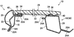
도 1에는, 차량용 패널 구조로서의 차량용 루프 구조(10)를 구성하는 차량 상부에 위치하는 금속제의 차량용 골격 부재(11) 및 패널 부재로서의 수지제의 루프 패널(28)의 개략 분해 사시도가 나타내어져 있고, 도 2에는, 차량용 골격 부재(11)에 루프 패널(28)이 접합된 상태가 나타내어져 있다.In FIG. 1, the schematic exploded perspective view of the metal vehicle
도 1에 나타낸 바와 같이, 차량용 골격 부재(11)의 차폭 방향의 양단부에는, 사이드 부재로서의 좌우 한 쌍의 루프 사이드 레일(12)이 차량 전후 방향을 따라 연장하여 설치되어 있다. 또, 차량용 골격 부재(11)의 차량 전단부 및 후단부에는, 크로스 부재로서의 프론트 헤더(14) 및 리어 헤더(16)가 차폭 방향을 따라 연장하여 설치되고, 한 쌍의 루프 사이드 레일(12) 사이에 걸쳐져 있다.As shown in Fig. 1, a pair of left and right roof side rails 12 as side members are provided at both ends in the vehicle width direction of the
도 3에는, 도 2의 A-A선 단면도가 나타내어져 있다. 도 3에 나타낸 바와 같이, 루프 사이드 레일(12)에서는, 차실 내측에 배치되는 루프 사이드 레일 이너(18)와, 차실 외측에 배치되는 루프 사이드 레일 아우터(20)가 설치되어 있고, 루프 사이드 레일 이너(18)와 루프 사이드 레일 아우터(20) 사이에는, 루프 사이드 리인포스(22)가 설치되어 있다.3 is a cross-sectional view taken along the line A-A of FIG. 3, the
루프 사이드 레일 이너(18), 루프 사이드 리인포스(22) 및 루프 사이드 레일 아우터(20)의 차폭 방향의 양단부에는, 각각 플랜지부(18A, 22A, 20A)가 설치되어 있고, 이들 플랜지부(18A, 22A, 20A)는 서로 접합되어 있다. 이것에 의해, 루프 사이드 레일 이너(18)와 루프 사이드 리인포스(22) 사이에서 폐단면이 형성되고, 루프 사이드 리인포스(22)와 루프 사이드 레일 아우터(20) 사이에서 폐단면이 형성된다.
한편, 도 2 및 도 3에 나타낸 바와 같이, 프론트 헤더(14) 및 리어 헤더(16)에서는[도 3에서는 리어 헤더(16) 측이 도시되어 있음], 차실 내측에 배치되는 헤더 로어(24)와, 차실 외측에 배치되는 헤더 어퍼(26)가 설치되어 있다. 헤더 로어(24) 및 헤더 어퍼(26)의 차량 전후 방향의 양단부에는, 플랜지부(24A, 26A)가 각각 설치되어 있고, 이들 플랜지부(24A, 26A)는 서로 접합되어 있다. 이것에 의해, 헤더 로어(24)와 헤더 어퍼(26) 사이에서 폐단면이 형성된다.2 and 3, the
여기서, 루프 패널(28)의 이면측(의장면의 반대측)의 차량 전단측의 모서리부에는, 대면하는 프론트 헤더(14)와 루프 사이드 레일(12) 사이를 걸치도록 하고, 고강성부로서의 각기둥 형상의 리브(30)가 루프 패널(28)과 일체로 설치되어 있다. 또, 루프 패널(28)의 차량 후단측의 모서리부에는, 리브(30)와 마찬가지로 리어 헤더(16)와 루프 사이드 레일(12) 사이를 걸치도록 하여, 고강성부로서의 각기둥 형상의 리브(32)가 형성되어 있다. 또한, 루프 패널(28)의 차량 전단측과 차량 후단측은 대략 동일한 구성으로 되어 있기 때문에, 이하는 루프 패널(28)의 차량 후단측의 리브(32)에 대하여 설명한다.Here, a corner between the
리브(32)의 길이 방향의 양단측에는, 오목부로서 대략 원기둥 형상으로 형성된 걸어맞춤 구멍(34)이 각각 형성되어 있다. 한편, 리어 헤더(16)의 헤더 어퍼(26)의 상면 및 루프 사이드 레일(12)의 루프 사이드 레일 아우터(20)에 설치된 플랜지부(20A)의 상면에는, 피걸어맞춤부로서의 웰 너트(36)가 각각 용접되어 있다. 걸어맞춤 구멍(34)은 당해 웰 너트(36)와 대향하는 위치에 설치되어 있고, 걸어맞춤 구멍(34) 내에 웰 너트(36)가 삽입 가능해진다(걸어맞춤 가능해진다).At both end sides in the longitudinal direction of the
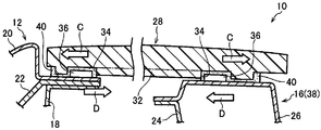
그리고, 루프 패널(28)의 걸어맞춤 구멍(34)과 헤더(38)[프론트 헤더(14) 및 리어 헤더(16)] 및 루프 사이드 레일(12)의 웰 너트(36)를 걸어맞춘 상태에서, 루프 패널(28)의 주연측에 설치된 접착제(40)를 개재하여, 루프 패널(28)이 헤더(38) 및 루프 사이드 레일(12)에 접합(고정)된다. 여기서, 접착제(40)는, 도 3 에 나타낸 바와 같이, 리브(32)의 길이 방향의 외측 및 걸어맞춤 구멍(34)과 웰 너트(36) 사이에서 생기는 간극에도 설치되어 있다.When the engaging
(차량용 루프 구조의 작용·효과)(Operation and Effect of Vehicle Loop Structure)
다음으로, 본 실시 형태에 관련된 차량용 패널 구조의 작용·효과에 대하여 설명한다.Next, the action and effect of the vehicle panel structure according to the present embodiment will be described.
도 1에 나타낸 바와 같이, 본 실시 형태에서는, 루프 패널(28)의 이면측의 각 모서리부에는, 헤더(38)[프론트 헤더(14) 및 리어 헤더(16)]와 루프 사이드 레일(12) 사이를 걸치도록 하여 리브(30, 32)가 각각 형성되어 있다. 그리고, 리브(32)[리브(30)에 대해서는 리브(32)와 대략 동일한 구성이기 때문에 설명을 생략함]의 길이 방향의 양단측에는, 걸어맞춤 구멍(34)이 각각 형성되고, 당해 걸어맞춤 구멍(34)에는, 헤더(38) 및 루프 사이드 레일(12)에 설치된 웰 너트(36)가 각각 걸어맞추어져 있다.1, a header 38 (
이와 같이, 루프 패널(28)에 리브(32)가 설치됨으로써, 리브(32)가 설치된 부분은 루프 패널(28)의 다른 부위보다 두께가 두꺼워진다. 이것에 의해, 루프 패널(28)을 보강할 수 있어, 루프 패널(28)의 강성을 높일 수 있다. 따라서, 차량 강성이 높아져, 조종 안정성 및 NV 성능이 향상된다.The
여기서, 헤더(38)와 루프 사이드 레일(12)의 각도 변화에 대해서는, 차량 평면에서 본 헤더(38)와 루프 사이드 레일(12)의 각도 이외에, 차량 측면에서 본 헤더(38)와 루프 사이드 레일(12)의 각도에 대해서도 동일하다. 이 때문에, 주행 시, 차량의 편측이 단차에 걸렸다고 하여도, 헤더(38)및 루프 사이드 레일(12) 등, 차량 골격 부재(11)를 개재하는 차량의 비틀림 변형이 방지 또는 억제된다.The change in the angle between the
또, 루프 패널(28)에 설치된 리브(32)에 형성된 걸어맞춤 구멍(34) 및 헤더(38)및 루프 사이드 레일(12)에 설치된 웰 너트(36)를 개재하여, 헤더(38)와 루프 사이드 레일(12)은 연결된다. 이 때문에, 헤더(38)와 루프 사이드 레일(12) 사이에서 압축 하중 또는 인장 하중이 작용한 경우, 웰 너트(36) 및 걸어맞춤 구멍(34)을 개재하여, 리브(32)에 의해 당해 압축 하중 또는 인장 하중에 대한 반력을 얻을 수 있다.The
즉, 도 4a에 나타낸 바와 같이, 헤더(38)와 루프 사이드 레일(12) 사이에서 압축 하중(화살표 A 방향)이 작용한 경우, 헤더(38)와 루프 사이드 레일(12)이 이루는 각도가 좁아지는 방향으로 헤더(38) 또는 루프 사이드 레일(12)이 변형하려고 한다. 이 때문에, 웰 너트(36) 및 걸어맞춤 구멍(34)을 개재하여 리브(32)[걸어맞춤 구멍(34)의 내측]에는, 압축 하중이 작용하지만, 당해 리브(32)는 고강성부로 되어 있기 때문에, 리브(32)를 개재하여 압축 하중에 대한 반력(화살표 B 방향)을 얻을 수 있다.4A, when the compression load (direction of arrow A) acts between the
한편, 도 4b에 나타낸 바와 같이, 헤더(38)와 루프 사이드 레일(12) 사이에서 인장 하중(화살표 C 방향)이 작용한 경우, 헤더(38)와 루프 사이드 레일(12)이 이루는 각도가 넓어지는 방향으로 헤더(38) 또는 루프 사이드 레일(12)이 변형하려고 한다. 이 때문에, 웰 너트(36) 및 걸어맞춤 구멍(34)을 개재하여 리브(32)[걸어맞춤 구멍(34)의 외측]에는, 인장 하중이 작용하지만, 당해 리브(32)는 고강성부로 되어 있기 때문에, 리브(32)를 통하여 인장 하중에 대한 반력(화살표 D 방향)을 얻을 수 있다.4B, when a tensile load (direction of arrow C) acts between the
여기서, 리브(32)의 길이 방향의 외측 및 걸어맞춤 구멍(34)과 웰 너트(36) 사이에서 생기는 간극에는, 접착제(40)가 설치되어 있다. 헤더(38)와 루프 사이드 레일(12) 사이에서 웰 너트(36) 및 걸어맞춤 구멍(34)을 개재하여 리브(32)에 압축 하중 및 인장 하중이 작용한 경우, 접착제(40)에 의해 당해 압축 하중 및 인장 하중에 대한 반력을 얻을 수 있다. 특히, 리브(32)의 길이 방향의 외측에 접착제(40)를 설치함으로써, 인장 하중에 대한 반력(화살표 D 방향)을 증대시킬 수 있다.An adhesive 40 is provided on the outer side in the longitudinal direction of the
이상으로부터, 루프 패널(28)에 수지를 사용해도, 헤더(38)와 루프 사이드 레일(12)이 이루는 각도는, 당해 루프 패널(28)에 설치된 리브(32) 및 접착제(40)를 개재하여 유지되게 된다. 따라서, 헤더(38)와 루프 사이드 레일(12) 사이의 각도 변화가 방지 또는 억제된다.The angle formed by the
또, 리브(32)는 루프 패널(28)과 일체로 설치되어 있다. 이것에 의해, 예를 들면, 두 부품을 일체화시키는 등의 2차 가공이 불필요해져, 비용 절감을 도모할 수 있지만, 당해 리브(32)를 루프 패널(28)과는 별도로 성형한 후, 루프 패널(28)과 일체화시켜도 되는 것은 물론이다. 이 경우, 리브(32)와 루프 패널(28)의 재료를 바꾸는 것이 가능해진다.The
또, 본 실시 형태에서는, 패널 부재가 루프 패널(28)이기 때문에, 캐빈의 비틀림 변형을 방지 또는 억제할 수 있다. 또, 루프 패널(28)에서는, 예를 들면 백 도어와 비교하여 형상이 단순하고, 리브(30, 32)를 설치하는 위치에 있어서, 디자인상 또는 기능상의 제한을 받지 않기 때문에, 차량 골격 부재 사이의 각도 변화를 억제한다는 기능을 충분히 발휘할 수 있다.Further, in the present embodiment, since the panel member is the
(그 밖의 실시 형태)(Other Embodiments)
(1) 본 실시 형태에서는, 도 3에 나타낸 바와 같이, 헤더(38) 및 루프 사이드 레일(12)의 상면에 웰 너트(36)가 용접되어, 루프 패널(28)에 설치된 리브(32)가 걸어맞추어지게 되어 있지만, 헤더(38)와 루프 사이드 레일(12)을 리브(32)에 의해 연결할 수 있으면 되기 때문에, 이에 한정되는 것은 아니다.(1) In the present embodiment, as shown in Fig. 3, the
예를 들면, 당해 웰 너트(36) 대신, 도 5에 나타낸 바와 같이, 관통 부재로서의 웰 볼트(42)를 사용하여 당해 웰 볼트(42)의 헤드부(42A)를 피걸어맞춤부로서 걸어맞춤 구멍(34)에 걸어 맞추어도 된다. 이 경우, 헤더(38)의 헤더 어퍼(26) 및 루프 사이드 레일(12)의 루프 사이드 레일 아우터(20), 루프 사이드 리인포스(22) 및 루프 사이드 레일 이너(18)의 플랜지부(20A, 22A, 18A)에는, 당해 웰 볼트(42)가 삽입되는, 관통 구멍(44)이 형성된다.For example, instead of the
이 관통 구멍(44)에 삽입된 상태에서 웰 볼트(42)가 헤더(38) 또는 루프 사이드 레일(12)에 용접되게 되지만, 웰 볼트(42)는 너트(46)에 의해 체결되기 때문에, 웰 너트(36)(도 3 참조)보다 웰 볼트(42) 쪽이, 헤더(38) 또는 루프 사이드 레일(12)에 대한 고정력(체결력)은 향상된다. 또, 너트(46)를 개재하여, 웰 볼트(42)가 빠짐 방지되기 때문에, 당해 웰 볼트(42)의 헤드부(42A), 리브(32)의 걸어맞춤 구멍(34) 및 접착제(40)를 개재하여, 루프 패널(28)의 부상을 방지 또는 억제할 수 있다.The
또, 여기서는, 웰 볼트(42)를 사용했지만, 관통 구멍(44)이 형성된 위치에 헤더 로어(24)에 있어서, 도시 생략하지만, 미리 웰 너트를 용접하여, 당해 웰 너트에 볼트를 체결시켜도 된다. 도 5에 나타낸 바와 같이, 웰 볼트(42)에 너트(46)를 체결시키는 경우, 헤더(38)의 헤더 로어(24)에는, 당해 너트(46)를 체결시키기 위한 작업 구멍(도시 생략)이 필요해지지만, 상기 서술한 바와 같이, 헤더 로어(24)에 미리 웰 너트를 용접하여, 당해 웰 너트에 볼트를 체결시키는 경우에는, 작업 구멍은 불필요하고, 또한 작업성도 좋다. 또한, 웰 너트(36)나 웰 볼트(42) 이외에, 도시 생략하지만, 헤더(38) 및 루프 사이드 레일(12)에 피걸어맞춤부로서의 원기둥 형상의 핀을 설치하고, 리브(32)에는 걸어맞춤부로서 당해 핀이 삽입되는 둥근 구멍을 형성해도 된다.Although a
(2) 또한, 이외에도, 도 6에 나타낸 바와 같이, 고강성부로서의 리브(48)의 양단측에, 리브(48)와 일체로 형성된, 돌기로서의 걸어맞춤 돌기(50)가 설치된 구성이어도 된다. 이 걸어맞춤 돌기(50)는, 헤더(38) 및 루프 사이드 레일(12)에 형성된 관통 구멍(44)에 삽입 가능하게 되어 있고, 걸어맞춤 돌기(50)의 선단부에는, 당해 관통 구멍(44)의 내경 치수보다 외경 치수가 큰 대략 원반 형상의 클로(claw)부(52)가 형성되어 있다.(2) In addition, as shown in FIG. 6, a configuration in which engaging
이 클로부(52)는, 예를 들면, 복수의 클로로 구성되어, 인접하는 클로 사이에는 간극이 설치되어 있다. 이 때문에, 클로부(52)가 관통 구멍(44)을 통과할 때에는, 클로 사이의 간극이 메워져 당해 클로부(52)가 축경(縮徑)되고, 관통 구멍(44)을 통과하면 클로부(52)가 복원되어 당해 클로부(52)가, 피걸어맞춤부로서의 관통 구멍(44)의 주연부에 걸어멈춤되어, 빠짐 방지되는 구성으로 되어 있다.The
즉, 관통 구멍(44) 및 클로부(52)를 개재하여, 헤더(38)와 루프 사이드 레일(12)은 리브(48)에 의해 연결된다. 이 경우, 웰 너트(36)(도 3 참조)나 웰 볼트(42)(도 5 참조) 등, 헤더(38) 및 루프 사이드 레일(12)과 리브(48)를 연결시키기 위한 별도의 부재가 불필요해져, 비용 절감을 도모할 수 있다.That is, the
(3) 또한, 상기의 실시 형태에서는, 도 3에 나타낸 바와 같이, 헤더(38)와 루프 사이드 레일(12) 사이를 리브(32)에 의해 연결하는 구성에 대하여 설명하였지만, 헤더(38)와 루프 사이드 레일(12)이 이루는 각도의 변화를 억제할 수 있으면 되기 때문에, 이에 한정되는 것은 아니다. 예를 들면, 헤더(38)와 루프 사이드 레일(12) 사이에 리브가 들어가는 구성이어도 된다.(3) In the above embodiment, as shown in Fig. 3, the structure in which the
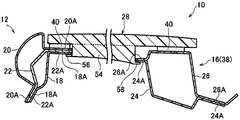
예를 들면, 도 7에 나타내는 바와 같이, 고강성부로서의 리브(54)의 양단부로부터, 리브(54)의 길이 방향을 따라 수납부(56, 58)가 돌출되고, 수납부(56)는 루프 사이드 레일 이너(18)의 플랜지부(18A) 아래에 배치되며, 수납부(58)는 헤더 로어(24)의 플랜지부(24A) 아래에 배치되도록 해도 된다. 그리고, 플랜지부(20A, 22A, 18A)의 선단면이 리브(54)의 길이 방향의 일단면과 대향하고, 플랜지부(26A, 24A)의 선단면이 리브(54)의 길이 방향의 타단면과 대향하며, 루프 패널(28)과 헤더(38)와 루프 사이드 레일(12)은 접착제(40)에 의해 접합된다.For example, as shown in FIG. 7, the
이 경우, 헤더(38)와 루프 사이드 레일(12) 사이에서 인장 하중이 작용한 경우, 리브(54)에 의한 반력은 얻어지지 않고, 접착제(40)에 의한 반력만이 헤더(38)와 루프 사이드 레일(12)에 작용하게 되지만, 헤더(38)와 루프 사이드 레일(12) 사이에서 압축 하중이 작용한 경우에는, 헤더(38) 및 루프 사이드 레일(12)의 플랜지부(20A, 22A, 18A), 플랜지부(26A, 24A)가, 수납부(56, 58)에 의해 지지된 상태에서 리브(54)의 단면에 각각 맞닿고, 이것에 의해 헤더(38)와 루프 사이드 레일(12)이 이루는 각도의 변화를 억제할 수 있다.In this case, when a tensile load acts between the
(본 실시 형태의 보충 설명)(Supplementary Explanation of Present Embodiment)
또한, 본 실시 형태에서는, 도 1에 나타내는 걸어맞춤 구멍(34)의 구멍 형상을 대략 원기둥 형상으로 하였지만, 웰 너트(36)의 외형 형상에 맞추어 각 형상을 이루도록 해도 된다. 이 경우, 웰 너트(36)에 걸어맞춤 구멍(34)이 걸어맞추어진 상태에서 당해 웰 너트(36)에 대하여 리브(32)가 회전 방지된다.In the present embodiment, the hole shape of the engaging
또, 본 실시 형태에서는, 헤더(38)로서 프론트 헤더(14) 및 리어 헤더(16)에 대하여 설명하였지만, 해치백 타입의 차량에 있어서, 적어도 리어 헤더(16) 측만 본 실시 형태에 관련된 차량용 루프 구조를 적용시켜도 된다. 차량 골격 부재에 있어서, 세단 타입의 차량에서는, 차량 전방측과 차량 후방측에서 변형의 차이는 적지만, 해치백 타입의 차량에서는, 차량 전방측보다 차량 후방측이 변형되기 쉬운 경향이 있다.In addition, although the
이 때문에, 해치백 타입의 차량에 있어서, 적어도 리어 헤더(16) 측을 보강함으로써, 필요 최소한의 구성으로 차량 골격 부재 사이에서 이루는 각도의 변형에 대하여 억제한다는 효과를 얻을 수 있다. 이 때문에, 프론트 헤더(14) 및 리어 헤더(16) 측을 보강한 경우와 비교하여, 비용 절감을 도모할 수 있다.Therefore, in the hatchback type vehicle, at least the side of the
또, 본 실시 형태에서는, 크로스 부재로서, 프론트 헤더(14) 및 리어 헤더(16)에 대하여 설명하였지만, 차량 전후 방향의 대략 중앙부에 루프 리인포스(도시 생략)가 설치된 경우, 당해 루프 리인포스에 본 실시 형태에 관련된 차량용 패널 구조를 적용시켜도 된다.In addition, in this embodiment, although the
또, 본 실시 형태에서는, 패널 부재로서 루프 패널(28)에 대하여 설명하였지만, 차량 골격 부재에 수지 패널을 접합시키는 지점이면 적용 가능하다. 예를 들면, 루프 패널(28) 이외에서는, 도 8a에 나타낸 후드(60)나 도 8b에 나타낸 백 도어(62) 등을 들 수 있고, 후드(60)나 백 도어(62)의 이면측의 모서리부에, 각각 고강성부로서의 리브(64)가 설치된다. 여기서, 백 도어(62)의 사이드 부재에 대하여, 「차량 전후 방향을 따라 연장하여 설치되어」란, 차량 후방을 향함에 따라 차량 하방으로 경사지는 방향으로 연장하여 설치되는 경우가 포함되지만, 차량 상하 방향을 따라서만 연장하여 설치된 경우도 포함된다.Although the
또한, 본 발명의 요지를 일탈하지 않는 범위에 있어서 여러 가지 태양으로 실시할 수 있음은 물론이다.Needless to say, the present invention can be carried out in various manners without departing from the gist of the present invention.
Claims (8)
상기 차량 골격 부재를 구성하고, 차폭 방향을 따라 연장하여 설치되며 상기 한 쌍의 사이드 부재 사이에 걸쳐진 크로스 부재를 구비한 차량에 적용되고,
상기 차량 골격 부재에 접합되는 수지제의 패널 부재와,
상기 패널 부재에 있어서 상기 사이드 부재와 상기 크로스 부재를 걸치는 위치에 설치되어, 당해 패널 부재의 다른 부위보다 강성이 높은 고강성부를 가지는 차량용 패널 구조.A pair of side members constituting a vehicle skeleton member and extending along the vehicle front-rear direction or the vehicle vertical direction;
And a cross member extending between the pair of side members so as to extend along the vehicle width direction and constitute the vehicle frame member,
A panel member made of resin bonded to the vehicle skeleton member;
The panel member for a vehicle having a high rigidity portion provided at a position across the side member and the cross member in the panel member and having a rigidity higher than that of other portions of the panel member.
상기 고강성부가 상기 패널 부재의 다른 부위의 두께보다 두꺼운 두께로 이루어진 리브인 차량용 패널 구조.The method of claim 1,
And the high rigidity portion is a rib made of a thickness thicker than the thickness of other portions of the panel member.
상기 사이드 부재 및 상기 크로스 부재에 설치된 피걸어맞춤부와 걸어맞추어지는 걸어맞춤부가 상기 리브에 설치된 차량용 패널 구조.3. The method of claim 2,
A vehicle panel structure in which the engaging portion engaged with the engaged portion provided in the side member and the cross member is provided in the rib.
상기 피걸어맞춤부가, 상기 사이드 부재 또는 상기 크로스 부재에 형성된 관통 구멍을 관통하여 빠짐 방지된 관통 부재에 설치되어 사이드 부재 또는 크로스 부재의 표면으로부터 돌출되는 헤드부이며, 상기 걸어맞춤부가, 상기 헤드부가 삽입되는 오목부인 차량 패널 구조.The method of claim 3,
The engaging portion is a head portion which is provided in a through member which is prevented from penetrating through a through hole formed in the side member or the cross member and protrudes from the surface of the side member or the cross member. Vehicle panel structure that is a recess to be inserted.
상기 피걸어맞춤부가, 상기 사이드 부재 또는 상기 크로스 부재에 형성된 관통 구멍의 주연부이며, 상기 걸어맞춤부가, 상기 관통 구멍을 관통하여 당해 관통 구멍의 주연부에 걸어멈추어지는 돌기인 차량 패널 구조.The method of claim 3,
The engaging portion is a peripheral portion of a through hole formed in the side member or the cross member, and the engaging portion is a protrusion passing through the through hole and stopped at a peripheral portion of the through hole.
상기 사이드 부재가 차량 전후 방향으로 연장하여 설치되고, 상기 패널 부재가 루프 패널인 차량용 패널 구조.The method according to any one of claims 1 to 5,
The side panel extends in the vehicle front-rear direction, and the panel member is a roof panel.
상기 리브의 길이 방향의 외측에 접착제가 도포된 차량용 패널 구조.The method according to any one of claims 2 to 6,
A vehicle panel structure in which an adhesive is applied to an outer side of the rib in the longitudinal direction.
상기 크로스 부재가, 상기 수지 루프 패널의 전단부에 배치되는 프론트 헤더부와, 상기 수지 루프 패널의 후단부에 배치되는 리어 헤더부를 포함하여 구성되고, 적어도 상기 리어 헤더부에 상기 고강성부가 설치된 차량용 패널 구조.8. The method according to any one of claims 1 to 7,
The cross member includes a front header portion disposed at a front end portion of the resin roof panel and a rear header portion disposed at a rear end portion of the resin roof panel, wherein at least the rear rigid portion has the high rigidity portion. Panel structure.
Applications Claiming Priority (1)
| Application Number | Priority Date | Filing Date | Title |
|---|---|---|---|
| PCT/JP2011/050377 WO2012095969A1 (en) | 2011-01-12 | 2011-01-12 | Panel structure for vehicle |
Publications (2)
| Publication Number | Publication Date |
|---|---|
| KR20130125802A true KR20130125802A (en) | 2013-11-19 |
| KR101454726B1 KR101454726B1 (en) | 2014-10-27 |
Family
ID=46506892
Family Applications (1)
| Application Number | Title | Priority Date | Filing Date |
|---|---|---|---|
| KR1020137020620A KR101454726B1 (en) | 2011-01-12 | 2011-01-12 | Resin roof panel structure |
Country Status (6)
| Country | Link |
|---|---|
| US (1) | US8899669B2 (en) |
| EP (1) | EP2664521B1 (en) |
| JP (1) | JP5494835B2 (en) |
| KR (1) | KR101454726B1 (en) |
| CN (1) | CN103282264B (en) |
| WO (1) | WO2012095969A1 (en) |
Families Citing this family (9)
| Publication number | Priority date | Publication date | Assignee | Title |
|---|---|---|---|---|
| FR2981325B1 (en) * | 2011-10-14 | 2013-10-25 | Saint Gobain | GLASS VEHICLE ROOF COMPRISING LOCAL COMPRESSION STRAIN ZONES |
| US9033401B1 (en) | 2014-03-20 | 2015-05-19 | Ford Global Technologies, Llc | Expandable roof panel perimeter reinforcement |
| US9162713B2 (en) | 2014-03-20 | 2015-10-20 | Ford Global Technologies, Llc | Expandable roof panel perimeter reinforcement |
| FR3040356B1 (en) * | 2015-08-25 | 2018-11-16 | Renault Sas | MOTOR VEHICLE HAVING AN OPENING ROOF PROVIDED WITH A RIGIDIFICATION ELEMENT |
| US9676426B1 (en) | 2016-02-17 | 2017-06-13 | Honda Motor Co., Ltd. | Vehicle roof structure |
| JP6699469B2 (en) | 2016-09-09 | 2020-05-27 | スズキ株式会社 | Body structure |
| US10029736B1 (en) * | 2017-01-17 | 2018-07-24 | Ford Global Technologies, Llc | Roof frame including a brace reinforcing arched members |
| DE102019122207A1 (en) * | 2019-08-19 | 2021-02-25 | Webasto SE | Arrangement for a vehicle roof, method for producing an arrangement for a vehicle roof and vehicle roof for a motor vehicle |
| JP7405024B2 (en) * | 2020-07-01 | 2023-12-26 | マツダ株式会社 | car body structure |
Family Cites Families (23)
| Publication number | Priority date | Publication date | Assignee | Title |
|---|---|---|---|---|
| DE2916013C2 (en) * | 1979-04-20 | 1987-11-12 | Dr.Ing.H.C. F. Porsche Ag, 7000 Stuttgart | Roof for vehicles, in particular automobiles for agricultural purposes |
| FR2498184A1 (en) | 1981-01-16 | 1982-07-23 | Rhone Poulenc Sante | PROCESS FOR THE PREPARATION OF QUINOLINONES-4 |
| JPS57171972U (en) * | 1981-04-24 | 1982-10-29 | ||
| DE3202594A1 (en) * | 1982-01-27 | 1983-08-11 | Ford-Werke AG, 5000 Köln | MOTOR VEHICLE BODY WITH A FIXED CONNECTED COMPOSITE ROOF |
| US4500311A (en) | 1983-02-23 | 1985-02-19 | American Hospital Supply Corporation | External ventricular drainage assembly |
| JPS59160466U (en) * | 1983-04-15 | 1984-10-27 | 日産自動車株式会社 | Plastic roof panel construction |
| JPS59164589U (en) * | 1983-04-20 | 1984-11-05 | 大黒工業株式会社 | Shutter type bath lid |
| DE3420781A1 (en) * | 1984-06-04 | 1985-01-31 | Stübbe GmbH, 2940 Wilhemshaven | ROOF FOR MOTOR VEHICLES |
| JPS6178076A (en) | 1984-09-25 | 1986-04-21 | 松下電工株式会社 | Connection structure for signal line |
| JPS6178076U (en) * | 1984-10-29 | 1986-05-24 | ||
| JPH0383183A (en) | 1989-08-28 | 1991-04-09 | Fujitsu Ltd | Broken line drawing system |
| JP2517165B2 (en) | 1990-07-27 | 1996-07-24 | 松下電器産業株式会社 | Control device for air conditioner |
| JPH0484057U (en) * | 1990-11-30 | 1992-07-22 | ||
| JP3971818B2 (en) | 1997-05-12 | 2007-09-05 | 本田技研工業株式会社 | Car body panel structure and joining method thereof |
| DE19835877B4 (en) * | 1997-08-07 | 2006-03-09 | Kabushiki Kaisha Toyota Jidoshokki, Kariya | vehicle window |
| US6860014B2 (en) * | 1998-06-18 | 2005-03-01 | Alcan Technology & Management Ltd. | Roof unit and basic structure of a road-bound vehicle |
| JP3436215B2 (en) * | 1999-11-24 | 2003-08-11 | 日産自動車株式会社 | Resin roof mounting structure |
| DE10158401B4 (en) * | 2001-11-28 | 2004-07-15 | Daimlerchrysler Ag | Moduldach for a motor vehicle and method for its assembly |
| ES2322696T3 (en) * | 2002-04-05 | 2009-06-25 | Grupo Antolin-Ingenieria, S.A. | VEHICLE ROOF MODULE. |
| DE10308582A1 (en) * | 2003-02-27 | 2004-09-30 | Arvinmeritor Gmbh | Method of manufacturing a vehicle body part |
| JP2008068765A (en) * | 2006-09-14 | 2008-03-27 | Mazda Motor Corp | Resin roof structure of vehicle |
| DE102008033923A1 (en) * | 2008-07-18 | 2010-01-21 | Webasto Ag | Vehicle component made of plastic |
| CN101695897A (en) * | 2009-10-27 | 2010-04-21 | 重庆长安汽车股份有限公司 | Mounting structure of automobile sunroof |
-
2011
- 2011-01-12 CN CN201180064350.9A patent/CN103282264B/en not_active Expired - Fee Related
- 2011-01-12 KR KR1020137020620A patent/KR101454726B1/en active IP Right Grant
- 2011-01-12 US US13/976,718 patent/US8899669B2/en active Active
- 2011-01-12 JP JP2012552570A patent/JP5494835B2/en not_active Expired - Fee Related
- 2011-01-12 EP EP11855306.4A patent/EP2664521B1/en not_active Not-in-force
- 2011-01-12 WO PCT/JP2011/050377 patent/WO2012095969A1/en active Application Filing
Also Published As
| Publication number | Publication date |
|---|---|
| EP2664521B1 (en) | 2016-11-02 |
| EP2664521A1 (en) | 2013-11-20 |
| CN103282264A (en) | 2013-09-04 |
| KR101454726B1 (en) | 2014-10-27 |
| US20130285417A1 (en) | 2013-10-31 |
| JP5494835B2 (en) | 2014-05-21 |
| EP2664521A4 (en) | 2015-07-22 |
| US8899669B2 (en) | 2014-12-02 |
| CN103282264B (en) | 2016-01-13 |
| JPWO2012095969A1 (en) | 2014-06-09 |
| EP2664521A8 (en) | 2014-01-08 |
| WO2012095969A1 (en) | 2012-07-19 |
Similar Documents
| Publication | Publication Date | Title |
|---|---|---|
| KR101454726B1 (en) | Resin roof panel structure | |
| US8979173B2 (en) | Vehicle body floor structure for automobile | |
| US9896131B2 (en) | Vehicle floor portion structure | |
| JP5920527B2 (en) | Automobile front pillar lower structure | |
| JP4272626B2 (en) | Lower body structure | |
| US8262155B2 (en) | Overmolded joint for beam assembly | |
| US9266568B2 (en) | Vehicle body lower section structure | |
| EP2740651B1 (en) | Vehicle body lateral structure | |
| JP5593813B2 (en) | Body reinforcement structure | |
| CN100390007C (en) | Rear body structure of vehicle | |
| CA2756721C (en) | Structure for vehicle body upper portion | |
| JP5924345B2 (en) | Resin floor structure of the vehicle | |
| WO2014185154A1 (en) | Top part structure of vehicle body | |
| JP2008105561A (en) | Vehicle front part structure | |
| JP5545124B2 (en) | Vehicle roof structure | |
| JP2009126197A (en) | Rear structure of vehicle body | |
| WO2015146902A1 (en) | Vehicle body side structure | |
| WO2015146903A1 (en) | Vehicle body side structure | |
| JP6147789B2 (en) | Rear structure of the car body | |
| JP5803685B2 (en) | Body structure | |
| JP4734294B2 (en) | Frame structure of the upper corner at the rear of the vehicle | |
| US20200269924A1 (en) | Structure for vehicle | |
| JP4729015B2 (en) | Connecting member for body frame | |
| JP6122968B2 (en) | Child anchor structure | |
| KR101857030B1 (en) | Support structure of tail-gate opening |
Legal Events
| Date | Code | Title | Description |
|---|---|---|---|
| A201 | Request for examination | ||
| A302 | Request for accelerated examination | ||
| E902 | Notification of reason for refusal | ||
| E701 | Decision to grant or registration of patent right | ||
| GRNT | Written decision to grant | ||
| FPAY | Annual fee payment |
Payment date: 20170920 Year of fee payment: 4 |
|
| FPAY | Annual fee payment |
Payment date: 20181004 Year of fee payment: 5 |