KR20130124432A - Hydraulic control device with load pressure reduction and hydraulic valve block therefor - Google Patents
Hydraulic control device with load pressure reduction and hydraulic valve block therefor Download PDFInfo
- Publication number
- KR20130124432A KR20130124432A KR1020130049809A KR20130049809A KR20130124432A KR 20130124432 A KR20130124432 A KR 20130124432A KR 1020130049809 A KR1020130049809 A KR 1020130049809A KR 20130049809 A KR20130049809 A KR 20130049809A KR 20130124432 A KR20130124432 A KR 20130124432A
- Authority
- KR
- South Korea
- Prior art keywords
- pressure
- hydraulic
- valve
- control
- line
- Prior art date
Links
Images


Classifications
-
- F—MECHANICAL ENGINEERING; LIGHTING; HEATING; WEAPONS; BLASTING
- F15—FLUID-PRESSURE ACTUATORS; HYDRAULICS OR PNEUMATICS IN GENERAL
- F15B—SYSTEMS ACTING BY MEANS OF FLUIDS IN GENERAL; FLUID-PRESSURE ACTUATORS, e.g. SERVOMOTORS; DETAILS OF FLUID-PRESSURE SYSTEMS, NOT OTHERWISE PROVIDED FOR
- F15B19/00—Testing; Calibrating; Fault detection or monitoring; Simulation or modelling of fluid-pressure systems or apparatus not otherwise provided for
-
- E—FIXED CONSTRUCTIONS
- E02—HYDRAULIC ENGINEERING; FOUNDATIONS; SOIL SHIFTING
- E02F—DREDGING; SOIL-SHIFTING
- E02F9/00—Component parts of dredgers or soil-shifting machines, not restricted to one of the kinds covered by groups E02F3/00 - E02F7/00
- E02F9/20—Drives; Control devices
- E02F9/22—Hydraulic or pneumatic drives
- E02F9/2221—Control of flow rate; Load sensing arrangements
- E02F9/2232—Control of flow rate; Load sensing arrangements using one or more variable displacement pumps
-
- E—FIXED CONSTRUCTIONS
- E02—HYDRAULIC ENGINEERING; FOUNDATIONS; SOIL SHIFTING
- E02F—DREDGING; SOIL-SHIFTING
- E02F3/00—Dredgers; Soil-shifting machines
- E02F3/04—Dredgers; Soil-shifting machines mechanically-driven
- E02F3/28—Dredgers; Soil-shifting machines mechanically-driven with digging tools mounted on a dipper- or bucket-arm, i.e. there is either one arm or a pair of arms, e.g. dippers, buckets
- E02F3/30—Dredgers; Soil-shifting machines mechanically-driven with digging tools mounted on a dipper- or bucket-arm, i.e. there is either one arm or a pair of arms, e.g. dippers, buckets with a dipper-arm pivoted on a cantilever beam, i.e. boom
- E02F3/32—Dredgers; Soil-shifting machines mechanically-driven with digging tools mounted on a dipper- or bucket-arm, i.e. there is either one arm or a pair of arms, e.g. dippers, buckets with a dipper-arm pivoted on a cantilever beam, i.e. boom working downwardly and towards the machine, e.g. with backhoes
- E02F3/325—Backhoes of the miniature type
-
- E—FIXED CONSTRUCTIONS
- E02—HYDRAULIC ENGINEERING; FOUNDATIONS; SOIL SHIFTING
- E02F—DREDGING; SOIL-SHIFTING
- E02F9/00—Component parts of dredgers or soil-shifting machines, not restricted to one of the kinds covered by groups E02F3/00 - E02F7/00
- E02F9/20—Drives; Control devices
- E02F9/22—Hydraulic or pneumatic drives
- E02F9/2278—Hydraulic circuits
- E02F9/2285—Pilot-operated systems
-
- E—FIXED CONSTRUCTIONS
- E02—HYDRAULIC ENGINEERING; FOUNDATIONS; SOIL SHIFTING
- E02F—DREDGING; SOIL-SHIFTING
- E02F9/00—Component parts of dredgers or soil-shifting machines, not restricted to one of the kinds covered by groups E02F3/00 - E02F7/00
- E02F9/20—Drives; Control devices
- E02F9/22—Hydraulic or pneumatic drives
- E02F9/2278—Hydraulic circuits
- E02F9/2296—Systems with a variable displacement pump
-
- F—MECHANICAL ENGINEERING; LIGHTING; HEATING; WEAPONS; BLASTING
- F15—FLUID-PRESSURE ACTUATORS; HYDRAULICS OR PNEUMATICS IN GENERAL
- F15B—SYSTEMS ACTING BY MEANS OF FLUIDS IN GENERAL; FLUID-PRESSURE ACTUATORS, e.g. SERVOMOTORS; DETAILS OF FLUID-PRESSURE SYSTEMS, NOT OTHERWISE PROVIDED FOR
- F15B11/00—Servomotor systems without provision for follow-up action; Circuits therefor
- F15B11/16—Servomotor systems without provision for follow-up action; Circuits therefor with two or more servomotors
- F15B11/161—Servomotor systems without provision for follow-up action; Circuits therefor with two or more servomotors with sensing of servomotor demand or load
- F15B11/165—Servomotor systems without provision for follow-up action; Circuits therefor with two or more servomotors with sensing of servomotor demand or load for adjusting the pump output or bypass in response to demand
-
- F—MECHANICAL ENGINEERING; LIGHTING; HEATING; WEAPONS; BLASTING
- F15—FLUID-PRESSURE ACTUATORS; HYDRAULICS OR PNEUMATICS IN GENERAL
- F15B—SYSTEMS ACTING BY MEANS OF FLUIDS IN GENERAL; FLUID-PRESSURE ACTUATORS, e.g. SERVOMOTORS; DETAILS OF FLUID-PRESSURE SYSTEMS, NOT OTHERWISE PROVIDED FOR
- F15B5/00—Transducers converting variations of physical quantities, e.g. expressed by variations in positions of members, into fluid-pressure variations or vice versa; Varying fluid pressure as a function of variations of a plurality of fluid pressures or variations of other quantities
-
- F—MECHANICAL ENGINEERING; LIGHTING; HEATING; WEAPONS; BLASTING
- F15—FLUID-PRESSURE ACTUATORS; HYDRAULICS OR PNEUMATICS IN GENERAL
- F15B—SYSTEMS ACTING BY MEANS OF FLUIDS IN GENERAL; FLUID-PRESSURE ACTUATORS, e.g. SERVOMOTORS; DETAILS OF FLUID-PRESSURE SYSTEMS, NOT OTHERWISE PROVIDED FOR
- F15B2211/00—Circuits for servomotor systems
- F15B2211/20—Fluid pressure source, e.g. accumulator or variable axial piston pump
- F15B2211/205—Systems with pumps
- F15B2211/2053—Type of pump
- F15B2211/20546—Type of pump variable capacity
- F15B2211/20553—Type of pump variable capacity with pilot circuit, e.g. for controlling a swash plate
-
- F—MECHANICAL ENGINEERING; LIGHTING; HEATING; WEAPONS; BLASTING
- F15—FLUID-PRESSURE ACTUATORS; HYDRAULICS OR PNEUMATICS IN GENERAL
- F15B—SYSTEMS ACTING BY MEANS OF FLUIDS IN GENERAL; FLUID-PRESSURE ACTUATORS, e.g. SERVOMOTORS; DETAILS OF FLUID-PRESSURE SYSTEMS, NOT OTHERWISE PROVIDED FOR
- F15B2211/00—Circuits for servomotor systems
- F15B2211/60—Circuit components or control therefor
- F15B2211/605—Load sensing circuits
-
- F—MECHANICAL ENGINEERING; LIGHTING; HEATING; WEAPONS; BLASTING
- F15—FLUID-PRESSURE ACTUATORS; HYDRAULICS OR PNEUMATICS IN GENERAL
- F15B—SYSTEMS ACTING BY MEANS OF FLUIDS IN GENERAL; FLUID-PRESSURE ACTUATORS, e.g. SERVOMOTORS; DETAILS OF FLUID-PRESSURE SYSTEMS, NOT OTHERWISE PROVIDED FOR
- F15B2211/00—Circuits for servomotor systems
- F15B2211/60—Circuit components or control therefor
- F15B2211/65—Methods of control of the load sensing pressure
- F15B2211/654—Methods of control of the load sensing pressure the load sensing pressure being lower than the load pressure
Abstract
Description
본 발명은 청구범위 제 1 항의 전제부에 따른 하중 감압부를 포함하는 유압 제어장치 및 청구범위 제 15 항의 전제부에 따른 상기 제어장치를 위한 유압 밸브 블록에 관한 것이다. The present invention relates to a hydraulic control device comprising a load reducing part according to the preamble of claim 1 and a hydraulic valve block for the control device according to the preamble of claim 15.
작업 기계에서, 특히 예를 들어 콤팩트형 또는 소형 굴착기, 백호로더(backhoe loader) 또는 텔레스코픽 핸들러(telescopic handler)와 같은 콤팩트한 이동식 디자인에서 유압 컨슈머에는 유압 펌프에 의해 바람직하게 조절 가능한 송출 체적이 공급된다. 체적 흐름의 분배는 제어 밸브들에 의해 이루어지고, 상기 제어 밸브들은 다수의 컨슈머들의 작동시에도 균형적인 이동 시퀀스를 보장해야 한다. 유압 펌프의 송출 체적 흐름의 조절은 하중 감지 시스템의 경우에 펌프 조절기에 의해 이루어지고, 상기 펌프 조절기에 한편으로는 컨슈머의 최대 하중 압력 및 다른 한편으로는 유압 펌프의 송출 압력이 전송된다. 유압 컨슈머로 하중 압력 보상 압력 매체 분배(LUDV)를 위해, 제어 밸브들 후방에 각각 개별 압력 유지 밸브들이 접속될 수 있고, 상기 모든 개별 압력 유지 밸브들에 폐쇄 방향으로 컨슈머의 최대 하중 압력이 공급된다. 그와 달리 하중 감지 원리(LS)에서 개별 압력 유지 밸브들은 제어 밸브 전방에 접속되고, 모든 개별 압력 유지 밸브들에 개방 방향으로 해당 컨슈머의 하중 압력이 공급된다. In the working machine, in particular in a compact mobile design, for example a compact or compact excavator, a backhoe loader or a telescopic handler, the hydraulic consumer is supplied with a discharge volume which is preferably adjustable by a hydraulic pump. . Distribution of the volume flow is made by control valves, which must ensure a balanced sequence of movements even in the operation of multiple consumers. The adjustment of the delivery volume flow of the hydraulic pump is made by a pump regulator in the case of a load sensing system, in which the maximum load pressure of the consumer on the one hand and the delivery pressure of the hydraulic pump on the other hand are transmitted. For load pressure compensation pressure medium distribution (LUDV) with a hydraulic consumer, individual pressure retention valves can be connected to the rear of the control valves, respectively, and all the individual pressure retention valves are supplied with the maximum load pressure of the consumer in the closing direction. . On the contrary, in the load sensing principle LS, the individual pressure holding valves are connected in front of the control valve, and all the individual pressure holding valves are supplied with the load pressure of the corresponding consumer in the open direction.
일반적으로 이러한 하중 감지 제어시 유압 펌프의 송출 체적 흐름이 조절되므로, 조작자는 유압 컨슈머(들)의 속도를 조절할 수 있다. 유압 펌프의 송출 압력은 컨슈머(들)의 저항에 따라 자동으로 제어된다. 상기 압력은 최대 시스템 압력으로 제한된다. 따라서 실린더 내의 압력은 제어되지 않기 때문에, 실린더 힘 및 작업 운동의 가속도 제어되지 않는다. 이러한 특성은 특히 질량과 관련된 작업 운동, 예컨대 회전 또는 붐이 덜컥거리게 하고 진동을 갖게 한다. 이는 기계의 작업 운동의 제어 가능성을 떨어뜨리고, 작동 기계의 구조에 바람직하지 않게 작용하고, 파손 및 고장을 일으킬 수 있다. In general, since the delivery volume flow of the hydraulic pump is controlled during such load sensing control, the operator can adjust the speed of the hydraulic consumer (s). The delivery pressure of the hydraulic pump is automatically controlled in accordance with the resistance of the consumer (s). The pressure is limited to the maximum system pressure. Therefore, since the pressure in the cylinder is not controlled, the acceleration of the cylinder force and the working motion is not controlled. This property makes the working movements, especially those associated with mass, such as rotation or boom rattle and cause vibration. This reduces the controllability of the working movement of the machine, undesirably affects the structure of the operating machine, and can cause breakage and failure.
이러한 단점을 제거하기 위해, 선행기술에는 예컨대 스로틀을 통해 체적 흐름 조절에 관여하는 최대 하중 압력에 대한 압력 의존적 누설이 제공됨으로써 시스템 내의 압력 상승 거동에 영향을 미치는 것이 공지되어 있다. 이로 인해 컨슈머의 가속 단계에서 압력 상승이 댐핑될 수 있다. 그러나 누설 흐름은 이러한 간단한 해결 방법에서 하중 의존적이고, 정지 상태에서도 즉, 가속이 이루어지지 않는 경우에도 존재하기 때문에, 이로 인해 바람직하지 않게 유압 펌프는 누설 흐름을 영구적으로 보상해야 하고, 이는 유압 컨슈머의 구동을 위해 전체 펌프 출력이 이용될 수 없게 하고 효율이 낮아지게 한다. In order to eliminate this drawback, it is known in the prior art to provide pressure dependent leakage to the maximum load pressure involved in volume flow control, for example via a throttle, to influence the pressure rise behavior in the system. This may damp the pressure rise in the acceleration phase of the consumer. However, since leakage flow is load-dependent in this simple solution and exists even at standstill, i.e. without acceleration, this undesirably causes the hydraulic pump to permanently compensate for the leakage flow, which causes The total pump output is not available for operation and the efficiency is lowered.
측정 개구를 갖고 압력 매체 체적 흐름을 컨슈머에 대해 조절할 수 있는 제어 밸브의 제어 영역을 더 잘 이용하기 위해, DE 10 2004 061 555 A1호에는 조절 가능한 LS-펌프 장치를 포함하는 유압 제어 장치가 공지되어 있다. LS-라인을 통해 측정 개구 후방에 접속된 개별 압력 유지 밸브로 최대 압력이 전송된다. LS-라인은 흐름 조절기를 통해 압력 매체 싱크에 연결되고, 이 경우 흐름 조절기는 펌프 속도에 따라 조절될 수 있다. 조절은, 펌프의 속도가 증가할수록 누설이 감소하도록 이루어진다. 이 경우, 펌프 조절에 작용하는 하중 감압은 관련되지 않는다. 그 대신 LS-라인의 의도대로 발생된 누설에 의해 제어 밸브의 측정 개구에서 유효한 압력차가 감소된다. 따라서 컨슈머로 송출된 체적 흐름은 더 작아진다. In order to better use the control area of the control valve which has a measuring opening and can regulate the pressure medium volume flow to the consumer,
이러한 해결 방법에서도, 유압 펌프로 대체되어야 하는 하중 전송 라인으로부터 영구적인 누설 흐름이 제공되는 것이 단점이다. 이는 펌프 출력의 완전한 이용을 저지하고, 효율을 감소시킨다. Even in this solution, the disadvantage is that a permanent leakage flow is provided from the load transmission line which has to be replaced by a hydraulic pump. This prevents the full use of the pump output and reduces the efficiency.
본 발명의 과제는 증가된 효율을 갖는 유압 제어 장치와 이를 위한 제어 블록을 제공하는 것이다. An object of the present invention is to provide a hydraulic control device having an increased efficiency and a control block therefor.
상기 과제는 청구범위 제 1 항의 특징을 포함하는 하중 압력 감압부를 가진 유압 제어장치 및 청구범위 제 15 항의 특징을 포함하는 이를 위한 유압 밸브 블록에 의해 해결된다. The problem is solved by a hydraulic control device having a load pressure reducing section comprising the features of claim 1 and a hydraulic valve block for this comprising the features of claim 15.
유압 제어장치의 바람직한 개선예들은 청구범위 제 2 항 내지 제 14 항에서 설명된다. Preferred refinements of the hydraulic control device are described in
특히 예를 들어 콤팩트형 또는 소형 굴착기, 백호로더 또는 텔레스코픽 핸들러와 같은 이동식 작업 기계를 위한 유압 제어 장치는 유압 펌프를 포함하고, 상기 펌프의 송출 라인을 통해 적어도 하나의 유압 컨슈머에 압력 매체가 공급될 수 있다. 또한, 상기 제어장치는 펌프 조절기를 포함하고, 상기 펌프 조절기에 의해 유압 컨슈머(들)의 송출 압력 및 최대 하중 압력에 따라, 특히 유압 펌프의 조절과 관련해서 유압 펌프의 조절 장치의, 시간적으로 제한된 조절 체적 흐름이 조절될 수 있다. 또한, 유압 제어 장치는 최대 하중 압력에 대한 감압 장치를 포함한다. 본 발명에 따라 감압 장치는 조절 체적 흐름에 따라 조절될 수 있다. In particular, hydraulic control devices for mobile work machines such as, for example, compact or compact excavators, backhoe loaders or telescopic handlers, comprise a hydraulic pump, through which the pressure medium is supplied to at least one hydraulic consumer via the delivery line of the pump. Can be. In addition, the control device includes a pump regulator, which is limited in time by the pump regulator in accordance with the delivery pressure and the maximum load pressure of the hydraulic consumer (s), in particular with respect to the adjustment of the hydraulic pump. The regulating volume flow can be adjusted. The hydraulic control device also includes a pressure reducing device for maximum load pressure. According to the invention the pressure reduction device can be adjusted according to the control volume flow.
이로써 최대 하중 압력의 감압, 또는 최대 하중 압력을 갖는 체적으로부터 누설 흐름("블리드 오프(Bleed-off)")은 선행기술과 달리 유압 펌프의 송출 체적 흐름 또는 하중 압력의 레벨이 아니라, 유압 펌프의 조절에 관련될 수 있고, 특히 관련된다. 즉, 하중 압력은 조절 체적 흐름이 제공되고, 그에 따라 유압 펌프의 송출 체적이 변경되는 경우에만 감소된다 .이 경우 펌프 조절기(조절 체적 흐름)의 이미 존재하는 "신호"가 이용된다. 선행기술과 달리, 감압은 유압 컨슈머(들)이 가속되는(네가티브 또는 포지티브) 작동 상태와 직접 관련되는 장점을 제공한다. 이는 유압 컨슈머(들)의 정지 상태에서, 즉 가속될 필요가 없는 경우에, 감압이 생략될 수 있게 한다. 따라서, 감소되지 않은 펌프 출력이 제공되고, 이는 상기 유압 컨슈머의 효율을 높이고 더 높은 작업 속도를 가능하게 한다. This allows the leakage of the maximum load pressure, or the leakage flow from the volume with the maximum load pressure ("bleed-off"), unlike the prior art, is not the level of the output volume flow or load pressure of the hydraulic pump, but rather the level of the hydraulic pump. May be involved, in particular related. In other words, the load pressure is reduced only when the regulating volume flow is provided, and accordingly the delivery volume of the hydraulic pump is changed. In this case the already existing "signal" of the pump regulator (regulating volume flow) is used. Unlike the prior art, decompression offers the advantage of being directly related to the operating state in which the hydraulic consumer (s) is accelerated (negative or positive). This allows the decompression to be omitted in the stationary state of the hydraulic consumer (s), ie when it does not need to be accelerated. Thus, an unreduced pump output is provided, which increases the efficiency of the hydraulic consumer and enables higher working speeds.
본 발명의 바람직한 그리고 특히 바람직한 개선예에서 감압 장치는, 유압 펌프의 송출 체적의 증가를 위한 조절 체적 흐름이 클수록 최대 하중 압력의 감압이 커지도록 조절될 수 있다. 이로 인해 하나 또는 다수의 유압 컨슈머의 부드러운 가속 또는 충격 없는 시동이 가능해진다. 또한, 진동이 감소된다. 이는, 유압 컨슈머의 질량이 큰 하중이 가속되어야 하는 경우에 특히 바람직하다. In a preferred and particularly preferred refinement of the invention, the decompression device can be adjusted such that the greater the depressurization of the maximum load pressure, the greater the control volume flow for increasing the delivery volume of the hydraulic pump. This allows smooth acceleration or shock-free starting of one or more hydraulic consumers. In addition, vibration is reduced. This is particularly desirable when a load with a large mass of hydraulic consumer is to be accelerated.
특히 바람직한 그리고 바람직한 다른 개선예에서 감압 장치는, 유압 펌프의 송출 체적의 증가를 위한 조절 체적 흐름이 0인 경우에, 최대 하중 압력의 감압이 대략 O이 되도록 조절될 수 있다. 이는 바람직하게, 어떠한 컨슈머도 송출 체적의 변동을 요구하지 않는 경우이므로, 유압 펌프의 조절도 필요 없다. 유압 펌프는 조절된 고정 상태이다. 즉, 펌프 조절기의 조절 체적 흐름도 약간의 누설을 제외하면 0이다. 이러한 조절된 상태에서 최대 하중 압력이 감소하지 않는 경우에 또는 최대 하중 압력을 갖는 체적으로부터 누설 흐름("블리드 오프")이 0인 경우에, 이로 인해 바람직하게 조절된 상태에서 누설 흐름을 공급하는 유압 펌프의 출력량은 0에 가까워진다. 따라서 유압 컨슈머(들)에 전체 펌프 출력이 제공될 수 있다. 이로 인해 조절된 상태에서 유압 컨슈머(들)의 더 높은 운동 속도가 달성될 수 있다. 따라서 유압 제어 장치의 효율이 높아진다.In another particularly preferred and preferred refinement, the decompression device can be adjusted such that the decompression of the maximum load pressure is approximately O when the regulating volume flow for increasing the delivery volume of the hydraulic pump is zero. This is preferably the case where no consumer requires a fluctuation in the delivery volume, so that no adjustment of the hydraulic pump is necessary. The hydraulic pump is in a regulated fixed state. That is, the adjusting volume flow chart of the pump regulator is zero except for a slight leakage. If the maximum load pressure does not decrease in this regulated state or if the leakage flow (“bleed off”) is zero from the volume with the maximum load pressure, this results in the hydraulic pressure supplying the leakage flow in a preferably regulated state. The output of the pump is close to zero. Thus, the total pump output can be provided to the hydraulic consumer (s). This allows higher movement speeds of the hydraulic consumer (s) to be achieved in the adjusted state. Therefore, the efficiency of the hydraulic control device is increased.
바람직한 개선예에서 감압 장치는 하중 압력 접속부와 저압 접속부를 가진 비례 방향 밸브를 포함한다. 이 경우 최대 하중 압력을 공급할 수 있는 하중 전송 라인을 갖는 하중 압력 접속부와 저압 접속부는 특히 저압 라인을 통해 압력 매체 싱크, 특히 탱크에 연결될 수 있다. 비례 방향 밸브로서 구현은 장치 기술적으로 간단하고, 최대 하중 압력의 계량된 감압을 가능하게 한다. In a preferred refinement, the pressure reducing device comprises a proportional directional valve having a load pressure connection and a low pressure connection. In this case, the load pressure connection and the low pressure connection having a load transmission line capable of supplying the maximum load pressure can be connected to the pressure medium sink, in particular the tank, in particular via the low pressure line. The implementation as a proportional directional valve is device technically simple and enables metered decompression of the maximum load pressure.
바람직한 개선예에서 유압 제어 장치는 배출 라인을 포함하고, 상기 배출 라인을 통해 펌프 조절기의 배출 접속부는 압력 매체 싱크, 특히 탱크에 연결될 수 있다. In a preferred refinement, the hydraulic control device comprises a discharge line, through which the discharge connection of the pump regulator can be connected to a pressure medium sink, in particular a tank.
다른 바람직한 개선예에서 감압 장치의 비례 방향 밸브는 스로틀 단부 위치들은 물론, 하중 압력 접속부를 비례 방향 밸브의 저압 접속부에 연결할 수 있는 하나의 스로틀 단부 위치를 포함한다. 상기 비례 방향 밸브의 밸브 바디, 특히 밸브 피스톤 또는 밸브 슬라이드에는 스로틀 단부 위치의 방향으로 배출 라인의 배출 압력이 공급될 수 있다. 바람직하게 비례 방향 밸브는 스프링 예비 응력을 받는 차단 위치를 갖고, 상기 위치에 의해 하중 압력 접속부는 저압 접속부와 특히 실질적으로 누설 없이 분리될 수 있다. 특히 바람직하게, 감압 장치의 비례 방향 밸브는 2/2 비례 방향 밸브로서 형성된다. In another preferred refinement the proportional directional valve of the pressure reducing device comprises a throttle end position as well as one throttle end position capable of connecting the load pressure connection to the low pressure connection of the proportional directional valve. The valve body of the proportional valve, in particular the valve piston or valve slide, can be supplied with a discharge pressure of the discharge line in the direction of the throttle end position. Preferably the proportional directional valve has a blocking position under spring prestressing, by which the load pressure connection can be separated from the low pressure connection in particular substantially without leakage. Particularly preferably, the proportional directional valve of the pressure reducing device is formed as a 2/2 proportional directional valve.
특히 바람직한 개선예에서 배출 라인에는 스로틀 장치, 특히 일정하거나 또는 조절 가능한 횡단면을 갖는 스로틀이 배치된다. 감압 장치의 비례 방향 밸브의 밸브 바디에는 상기 스로틀 장치의 상류에서 배출 라인에 연결된 제어 라인을 통해 스로틀 단부 위치 방향으로 배출 압력이 공급될 수 있다. 이로 인해, 펌프 조절기의 조절 체적 흐름, 즉 이러한 경우에 펌프 조절기로부터 압력 매체 싱크로 배출 체적 흐름은 감압 장치의 비례 방향 밸브를 위한 조절 신호 생성기로서 사용될 수 있다. 펌프 조절기의 배출 체적 흐름이 클수록, 제어 라인 내의 압력이 커지고, 상기 압력은 감압 장치의 비례 방향 밸브의 밸브 바디를 차단 위치로부터 비례 방향 밸브의 스로틀 단부 위치 방향으로 이동시킨다. In a particularly preferred refinement the discharge line is arranged with a throttle device, in particular a throttle having a constant or adjustable cross section. The valve body of the proportional directional valve of the pressure reducing device can be supplied with a discharge pressure in the direction of the throttle end position via a control line connected to the discharge line upstream of the throttle device. As such, the regulating volume flow of the pump regulator, ie in this case the pressure medium sink discharge volume flow from the pump regulator, can be used as a regulating signal generator for the proportional directional valve of the pressure reducing device. The larger the discharge volume flow of the pump regulator, the greater the pressure in the control line, which moves the valve body of the proportional valve of the pressure reducing device from the shutoff position toward the throttle end position of the proportional valve.
바람직한 개선예에서 펌프 조절기는 비례 방향 밸브를 포함하고, 상기 밸브는 송출 라인 접속부를 포함하고, 상기 송출 라인 접속부를 통해 상기 비례 방향 밸브는 송출 라인에 연결될 수 있다. 또한, 상기 밸브는 펌프 조절기의 배출 접속부를 포함하고, 상기 배출 접속부를 통해 상기 밸브는 압력 매체 싱크, 특히 탱크에 연결될 수 있다. 또한, 상기 밸브는 조절 접속부를 포함하고, 상기 조절 접속부를 통해 상기 밸브는 조절 장치에 연결될 수 있다. 또한, 펌프 조절기의 비례 방향 밸브는 유입 위치 및 유입 단부 위치를 포함하고, 상기 유입 위치를 통해 상기 송출 라인은 특히 유입 체적 흐름을 형성하기 위해 조절 장치에 연결될 수 있다. 또한, 펌프 조절기의 비례 방향 밸브는 배출 위치 및 배출 단부 위치를 포함하고, 상기 배출 위치를 통해 조절 장치는 특히 배출 체적 흐름을 형성하기 위해 압력 매체 싱크에 연결될 수 있다. In a preferred refinement the pump regulator comprises a proportional directional valve, the valve comprising a delivery line connection, through which the proportional direction valve can be connected to the delivery line. The valve also comprises a discharge connection of a pump regulator, through which the valve can be connected to a pressure medium sink, in particular a tank. In addition, the valve may include a regulating connection, through which the valve may be connected to a regulating device. In addition, the proportional directional valve of the pump regulator comprises an inlet position and an inlet end position, through which the outlet line can in particular be connected to a regulating device to form an inlet volume flow. In addition, the proportional directional valve of the pump regulator includes a discharge position and a discharge end position, through which the regulating device can be connected in particular to the pressure medium sink to form a discharge volume flow.
특히 바람직한 개선예에서 펌프 조절기의 비례 방향 밸브의 밸브 바디에는 배출 단부 위치의 방향으로 최대 하중 압력 및 조절 스프링의 스프링 등량이 공급될 수 있고, 유입 단부 위치의 방향으로 유압 펌프의 송출 압력이 공급될 수 있다. 특히 바람직하게 펌프 조절기의 비례 방향 밸브는 3/2 비례 방향 밸브이다. In a particularly preferred refinement, the valve body of the proportional valve of the pump regulator can be supplied with the maximum load pressure in the direction of the discharge end position and the spring equivalent of the regulating spring, and the discharge pressure of the hydraulic pump in the direction of the inlet end position. Can be. Particularly preferably the proportional directional valve of the pump regulator is a 3/2 proportional directional valve.
감압 장치의 비례 방향 밸브가 그 차단 위치 방향으로 이동되는 동안 배출 체적 흐름이 감소할 때 전환 진동을 댐핑하기 위해, 본 발명의 바람직한 개선예는 제어 라인에 스로틀 장치 또는 스로틀 장치 및 이에 대해 병렬 접속되고 배출 압력에 의해 개방되는 체크 밸브를 포함한다. 이러한 해결 방법은 감압의 지연된 스위치 오프 또는 비활성화를 가능하게 하고, 따라서 시스템 다이내믹에 대한 조정을 가능하게 한다. In order to damp the switching vibrations when the discharge volume flow decreases while the proportional directional valve of the depressurization device is moved in the direction of its blocking position, a preferred refinement of the invention is connected to the throttle device or the throttle device and parallel to the control line And a check valve opened by the discharge pressure. This solution allows for delayed switch off or deactivation of the decompression, thus enabling adjustment to system dynamics.
최대 하중 압력의 감압을 의도대로 중단할 수 있도록 하기 위해, 배출 라인에 배치된 스로틀 장치는 스프링 예비 응력을 받은 스로틀 전환 위치 및 작동 가능한 관류 전환 위치를 갖는 방향 밸브로서 형성된다. 관류 전환 위치가 작동되지 않고 따라서 스로틀 기본 위치가 제공되면, 즉시 펌프 조절기로부터 배출 라인을 통해 충분한 크기의 배출 체적 흐름이 배출 라인 내로 흘러 배출 압력이 조절되고, 최대 하중 압력은 전술한 바와 같이 감소된다. 그와 달리 배출 라인의 스로틀 장치의 방향 밸브가 관류 전환 위치를 차지하도록 작동되면, 배출 라인에 이렇다할 배출 압력이 형성될 수 없으므로 감압 장치는 작동하지 않고, 바람직하게 최대 하중 압력의 감소가 이루어지지 않는다. In order to be able to stop the decompression of the maximum load pressure as intended, the throttle device disposed in the discharge line is formed as a directional valve having a spring prestressed throttle shift position and an actuated through flow shift position. If the perfusion diverting position is not activated and therefore the throttle base position is provided, immediately enough flow volume of discharge volume flows from the pump regulator through the discharge line into the discharge line to regulate the discharge pressure and the maximum load pressure is reduced as described above. . In contrast, when the directional valve of the throttle device of the discharge line is operated to occupy the perfusion switching position, the decompression device does not operate since no discharge pressure can be formed in the discharge line, and preferably no reduction in the maximum load pressure is achieved. .
이러한 개선예는, 유압 제어 장치가 다이내믹 작동 가능한 유압 컨슈머를 포함하고, 상기 컨슈머가 다이내믹 작동되는 경우에, 특히 바람직하다. 상기 컨슈머에 제어 밸브가 할당되고, 상기 제어 밸브는 유압 펌프의 송출 라인에 연결된다. 또한, 유압 제어장치의 이러한 개선예는 조작 유닛을 포함하고, 상기 조작 유닛은 제 1 제어 신호 라인을 통해 제 1 작업 위치의 제어를 위한 제어 밸브에 연결된다. 또한, 제 1 제어 신호 라인은 배출 라인의 스로틀 장치의 방향 밸브에 연결되므로, 상기 방향 밸브의 관류 전환 위치는 제 1 제어 신호 라인을 통해 전환될 수 있다. 다이내믹 작동 가능한 유압 컨슈머가 조작 유닛 및 제 1 제어 신호 라인에 의해 제어되는 경우에, 동시에 스로틀 장치의 방향 밸브가 관류 전환 위치로 제어되므로, 상기 작동 시간 동안 최대 하중 압력의 감압은 비활성화된다. This refinement is particularly preferred when the hydraulic control device comprises a hydraulically operable hydraulic consumer and the consumer is dynamically operated. A control valve is assigned to the consumer and the control valve is connected to the delivery line of the hydraulic pump. This refinement of the hydraulic control also includes an operation unit, which is connected to a control valve for control of the first working position via the first control signal line. Further, since the first control signal line is connected to the directional valve of the throttle device of the discharge line, the perfusion switching position of the directional valve can be switched via the first control signal line. In the case where the dynamically actuated hydraulic consumer is controlled by the operation unit and the first control signal line, at the same time, since the directional valve of the throttle device is controlled to the perfusion switching position, the decompression of the maximum load pressure is deactivated during the operation time.
다이내믹 작동 가능한 유압 컨슈머가 2개의 이동 방향을 갖는 경우에, 조작 유닛은 바람직하게 제 2 제어 신호 라인을 통해 제 2 작업 위치의 제어를 위한 제어 밸브에 연결된다. 제 2 제어 신호 라인도 배출 라인의 스로틀 장치의 방향 밸브에 연결되므로, 상기 방향 밸브의 관류 전환 위치는 제 2 제어 신호 라인에 의해서도 제어될 수 있다. 이로 인해 유압 컨슈머의 다이내믹 작동을 위한 최대 하중 압력의 감압은 2개의 작업 방향으로 비활성화될 수 있다.In the case where the dynamically operable hydraulic consumer has two directions of movement, the operation unit is preferably connected to a control valve for control of the second working position via the second control signal line. Since the second control signal line is also connected to the directional valve of the throttle device of the discharge line, the perfusion switching position of the directional valve can also be controlled by the second control signal line. This allows the decompression of the maximum load pressure for the dynamic operation of the hydraulic consumer to be deactivated in two working directions.
다이내믹 작동 가능한 유압 컨슈머의 제어 밸브가 조작 유닛을 통해 제어 압력에 의해 제어되는 경우에, 제 1 및 제 2 제어 신호 라인은 제어 압력 라인이다. 상기 제어 압력 라인들은 셔틀 밸브의 입력부에 연결되고, 이 경우 셔틀 밸브의 출력부는 배출 라인의 스로틀 장치의 방향 밸브의 제어 압력 입력부에 연결된다. 이로 인해 다이내믹 유압 컨슈머의 최대 제어 압력은 항상 방향 밸브의 제어 압력 입력부에 접속된다. In the case where the control valve of the dynamic actuated hydraulic consumer is controlled by the control pressure through the operation unit, the first and second control signal lines are control pressure lines. The control pressure lines are connected to the input of the shuttle valve, in which case the output of the shuttle valve is connected to the control pressure input of the directional valve of the throttle device of the discharge line. This ensures that the maximum control pressure of the dynamic hydraulic consumer is always connected to the control pressure input of the directional valve.
바람직하게 유압 펌프는 축방향 피스톤 또는 방사방향 피스톤 또는 베인 펌프로서 형성된다.Preferably the hydraulic pump is formed as an axial piston or radial piston or vane pump.
바람직하게 유압 펌프는 일정한 속도로 작동한다. 이와 달리 상기 유압 펌프는 가변 속도로 작동할 수도 있다. Preferably the hydraulic pump operates at a constant speed. Alternatively, the hydraulic pump may operate at variable speeds.
하중 감지 원리(LS) 또는 하중 압력 보상 압력 매체 분배(LUDV) 원리에 따라 구성된 유압 제어장치 내의 최대 하중 압력의 전술한 감압이 특히 바람직한 것으로 입증된다. 전자의 경우에 유압 펌프의 송출 라인 내에 각각의 유압 컨슈머 마다 하나의 측정 개구가 할당되고, 상기 측정 개구의 상류에 각각 하나의 개별 압력 유지 밸브가 할당된다. 이 경우 개별 압력 유지 밸브에 그 개방 방향으로 할당된 유압 컨슈머의 하중 압력이 공급되고, 그 폐쇄 방향으로 개별 압력 유지 밸브와 측정 개구 사이의 압력이 공급된다. 후자의 경우에(LUDV) 유압 펌프의 송출 라인에서 각각의 유압 컨슈머에 각각 하나의 측정 개구 및 개별 압력 유지 밸브가 할당된다. 개별 압력 유지 밸브는 측정 개구의 하류에 배치되고, 이 경우 각각의 개별 압력 유지 밸브에는 - LS 원리에서와 달리 - 폐쇄 방향으로 유압 컨슈머(들)의 최대 하중 압력이 공급되고, 개방 방향으로 측정 개구와 개별 압력 유지 밸브 사이의 압력이 공급된다.The above-mentioned decompression of the maximum load pressure in the hydraulic control device constructed in accordance with the load sensing principle LS or the load pressure compensation pressure medium distribution (LUDV) principle proves to be particularly desirable. In the former case, one measuring opening is assigned to each hydraulic consumer in the delivery line of the hydraulic pump, and one individual pressure retention valve is allocated upstream of the measuring opening. In this case, the load pressure of the hydraulic consumer assigned in the opening direction is supplied to the individual pressure retention valve, and the pressure between the individual pressure retention valve and the measurement opening is supplied in the closing direction. In the latter case (LUDV) in the delivery line of the hydraulic pump, one measuring opening and a separate pressure retention valve are each assigned to each hydraulic consumer. The individual pressure holding valves are arranged downstream of the measuring openings, in which case each individual pressure holding valve is supplied with the maximum load pressure of the hydraulic consumer (s) in the closing direction-in contrast to the LS principle-and in the opening direction. And pressure between the individual pressure retention valves is supplied.
유압 밸브 블록에 의한 최대 하중 압력의 본 발명에 따른 전술한 감압부는 장치 기술적으로 특히 콤팩트하게 구현될 수 있다. 적어도 하나의 유압 컨슈머에 압력 매체를 공급할 수 있는 송출 라인을 갖는 조절 가능한 유압 펌프의 제어를 위해 상기 유압 밸브 블록은 펌프 조절기를 포함하고, 상기 펌프 조절기에 의해 유 압 펌프의 송출 압력 및 유압 컨슈머(들)의 최대 하중 압력에 따라 특히 유압 펌프의 조절과 관련해서 시간적으로 제한된, 유압 펌프의 조절 장치를 위한 조절 체적 흐름이 조절될 수 있다. 또한, 밸브 블록은 최대 하중 압력을 위한 감압 장치를 포함한다. 본 발명에 따라 감압 장치는 조절 체적 흐름에 따라 조절될 수 있다. 유압 펌프, 유압 컨슈머(들), 펌프 조절기, 조절 체적 흐름, 유압 펌프의 조절 장치, 감압 장치, 이들의 작동 방식 및 상호 작용의 바람직한 개선예들은 전술한 설명에 상응한다. The above-mentioned decompression part according to the present invention of the maximum load pressure by the hydraulic valve block can be implemented in device technically particularly compactly. For control of an adjustable hydraulic pump having a delivery line capable of supplying pressure medium to at least one hydraulic consumer, the hydraulic valve block comprises a pump regulator, and by means of the pump regulator the delivery pressure and hydraulic consumer of the hydraulic pump ( The regulating volume flow for the regulating device of the hydraulic pump can be regulated in accordance with the maximum load pressure in particular. The valve block also includes a pressure reducing device for maximum load pressure. According to the invention the pressure reduction device can be adjusted according to the control volume flow. Hydraulic pumps, hydraulic consumer (s), pump regulators, regulating volume flow, regulators of hydraulic pumps, pressure reducing devices, preferred ways of their operation and interaction correspond to the foregoing description.
하기에서 본 발명에 따른 유압 제어장치의 3개의 실시예들은 3개의 회로도와 하나의 다이어그램을 참고로 설명된다. In the following three embodiments of a hydraulic control apparatus according to the invention are described with reference to three circuit diagrams and one diagram.
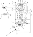
도 1은 하중 감압부를 포함하는 유압 제어장치의 제 1 실시예를 도시한 도면.
도 2는 하중 감압부의 댐핑을 포함하는 유압 제어장치의 제 2 실시예를 도시한 도면.
도 3은 하중 압력 감압부의 차단 및 도 2에 따른 댐핑을 포함하는 유압 제어장치의 제 3 실시예를 도시한 도면.
도 4는 3개의 실시예들의 펌프 조절기의 제어 다이어그램을 도시한 도면.1 shows a first embodiment of a hydraulic control device including a load reducing unit.
FIG. 2 shows a second embodiment of a hydraulic control device including damping of a load reducing part. FIG.
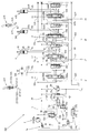
FIG. 3 shows a third embodiment of a hydraulic control device comprising blocking of the load pressure reducing part and damping according to FIG. 2.
4 shows a control diagram of a pump regulator of three embodiments.
도 1에 따라 콤팩트형 굴착기의 유압 제어장치(1)는 조절 가능한 송출 체적을 갖는 유압 펌프(2)를 포함한다. 유압 펌프(2)의 송출 라인(4)을 통해 다수의 유압 컨슈머들(도 3 참조)에 압력 매체가 공급될 수 있다. 상기 유압 컨슈머들 중에 도 1에 따라 제 1 유압 컨슈머(6)만이 도시되고, 상기 유압 컨슈머는 소형 굴착기의 붐의 제어를 위한 일측의 피스톤 로드를 포함하는 이중 로드 실린더에 의해 형성된다. 제 1 유압 컨슈머(6)의 제어를 위해 상기 컨슈머에 제어 밸브(8)가 할당된다. 제어 밸브(8)는 스프링으로 센터링된 차단 위치를 갖는 6/3 비례 방향 밸브로서 형성된다. 제어 밸브(8)는 작업 라인(10)을 통해 유압 펌프(2)의 송출 라인(4)에 연결되고, 작업 라인(12, 14)을 통해 제 1 유압 컨슈머(6)의 작업 챔버(16, 18)에 연결된다. 제어 밸브(8)의 조작을 위해 유압 제어 장치(1)는 조이스틱으로 형성된 조작 유닛(20)을 포함한다. 조작 유닛(20)은 2개의 제어 압력 라인(22, 24)에 연결되고, 상기 제어 압력 라인을 통해 제어 밸브(8)의 밸브 슬라이드(26)는 그 관류 위치들(8a, 8b)로 제어될 수 있다. 탱크(T)의 방향으로 유압 컨슈머(6)로부터 압력 매체를 배출하기 위해, 제어 밸브(8)는 탱크 접속부(T)를 포함하고, 상기 탱크 접속부는 탱크 라인(28)을 통해 탱크(T)에 압력 매체 연결된다.The hydraulic control device 1 of the compact type excavator according to FIG. 1 comprises a
유압 제어장치(1)는 하중 감지 원리에 기초한다. 이를 위해 상기 제어장치는 하중 전송 라인(30)을 포함하고, 상기 라인에서 유압 컨슈머(6)의 최대 하중 압력이 발생한다. 상기 최대 하중 압력은 유압 펌프(2)의 조절에 관여한다. 상기 유압 펌프는 펌프 조절기(32)를 포함하고, 상기 펌프 조절기는 3개의 접속부와 2개의 단부 위치를 갖는 비례 방향 밸브로서 형성된다. 펌프 조절기(32)는 압력 매체 라인(34)을 통해 간단하게 작용하는 유압 실린더로서 형성된 유압 펌프(2)의 조절 장치(36)에 연결된다. 또한, 압력 조절기(32)의 압력 접속부(P)는 압력 라인(38)을 통해 유압 펌프(2)의 송출 라인(4)에 연결된다. 또한 펌프 조절기(32)의 탱크 접속부(T)는 배출 라인(40)을 통해 탱크(T)에 압력 매체 연결된다. 펌프 조절기(32)는 유입 단부 위치(32a)와 배출 단부 위치(32b)를 갖는다. 펌프 조절기(32)의 밸브 피스톤(33)에는 상기 펌프 조절기의 유입 위치(32a)의 방향으로 송출 라인(4) 내의 송출 압력이 공급되고, 배출 위치(32b)의 방향으로 하중 전송 라인(30) 내의 최대 하중 압력 및 조절 스프링(32c)의 압력 등량이 공급된다. 상기 펌프 조절기는 단부 위치들 사이에서 계속해서 조절될 수 있다. The hydraulic control device 1 is based on the load sensing principle. For this purpose the control device comprises a
하중 전송 라인(30)으로부터 3개의 하중 압력 라인들(44, 46, 48)이 분기한다. 하중 압력 라인(44)에 최대 하중 압력의 제한을 위한 조절 가능한 압력 제한 밸브(50)가 배치된다. 압력 제한 밸브(50)는 하중 전송 라인(30)을 탱크(T)로 감압한다. 하중 감압 라인(46)에 흐름 조절기(52)가 배치된다. 상기 흐름 조절기는 유압 컨슈머가 압력 매체를 필요로 하지 않고 할당된 제어 밸브들이 그 차단 위치를 갖는 경우에, 하중 압력이 감압되므로, 유압 펌프가 컨슈머의 이러한 휴지 상태에서 고압을 공급하지 않게 한다. 이는 제어장치(1)의 에너지 효율에 기여한다. 흐름 조절기(52)는 최대 하중 압력과 무관하게, 즉 하중 상태에서도 하중 전송 라인으로부터 일정하게 0.7 l/m를 배출한다. 흐름 조절기(52)의 막힘 또는 손상을 방지하기 위해, 흐름 조절기(52) 전방에 필터(54)가 접속된다. Three
하중 압력 라인(48)에 하중 전송 라인(30) 내의 최대 하중 압력의 감소를 위한 본 발명에 따른 감압 장치(56)가 배치된다. 감압 장치(56)는 차단 위치(56a)에서 스프링 예비 응력을 받는 2/2 비례 방향 밸브로서 형성된다. 상기 방향 밸브는 차단 위치(56a) 외에 스로틀 단부 위치(56b)를 갖는다. 감압 장치(56)의 비례 방향 밸브는 탱크 접속부(T)를 포함하고, 상기 탱크 접속부는 저압 라인(58)을 통해 탱크(T)에 연결된다. 상기 비례 방향 밸브의 차단 위치(56a)의 방향으로 탱크 라인(58) 내의 압력 및 스프링(56c)의 압력 등량이 공급된다. 감압 장치(56)의 비례 방향 밸브에는 그 스로틀 단부 위치(56b)의 방향으로 배출 라인(40) 및 스로틀 장치(42) 상류의 배출 압력이 공급된다. 이를 위해 감압 장치(56)의 비례 방향 밸브는 제어 라인(60)을 통해 스로틀 장치(42) 상류의 배출 라인(40)에 연결된다. In the load pressure line 48 a
도 1의 제 1 실시예에 따른 하중 감지 유압 제어장치(1)는 하중 압력 보상 압력 매체 분배(LUDV)를 포함한다. 이를 위해 제어장치(1)는 제어 밸브(8)의 하류에 3/3 비례 방향 밸브로서 형성된 개별 압력 유지 밸브(62)를 갖는다. 상기 압력 유지 밸브는 차단 단부 위치(62a), 하나 또는 다수의 조절 위치(62b) 및 개방 단부 위치(62c)를 갖는다. 차단 단부 위치(62a)의 방향으로 개별 압력 유지 밸브(62)의 밸브 슬라이드(64)에는 하중 전송 라인(30) 내의 최대 하중 압력이 공급된다. 개방 단부 위치(62c)의 방향으로 개별 압력 유지 밸브(62)의 밸브 슬라이드(64)에는 측정 개구(66a) 또는 제어 밸브(8) 하류의 압력이 공급된다. 개별 압력 유지 밸브는 상기 압력 유지 밸브를 제어 밸브(8)의 압력 접속부(P')에 연결하는 압력 접속부(P), 상기 압력 유지 밸브를 하중 전송 라인(30)에 연결하는 하중 전송 접속부(L) 및 상기 개별 압력 유지 밸브를 유입 라인(68)을 통해 제어 밸브(8)의 유입 접속부(Z)에 연결하는 압력 접속부(P')를 갖는다. 유입 라인(68)에 유압 컨슈머(6)의 하중 감소를 저지하기 위해 컨슈머(6)를 향해 개방하는 체크 밸브(70)가 배치된다. The load sensing hydraulic control device 1 according to the first embodiment of FIG. 1 comprises a load pressure compensated pressure medium distribution LUDV. For this purpose the control device 1 has a separate
최대 하중 압력의 본 발명에 따른 감압부의 작동 방식이 설명된다. 제어장치(1)의 정지 작동 상태가 가정되고, 이러한 작동 상태에서 유압 컨슈머(6)는 하중을 지지하고 따라서 가속되어서는 안 된다. 이 시점에 유압 펌프(2)는 일정한 속도로 회전한다. 이제 유압 컨슈머(6)의 하중이 들어 올려진다. 이를 위해 조작자는 조작 유닛(20)을 이용하고, 상기 조작 유닛의 조이스틱은 제어 밸브(8)의 밸브 피스톤(26)에 제어 압력 라인(24)을 통해 제어 압력이 공급되도록 조절된다. 그리고 나서 도 1의 밸브 피스톤(26)은 아래로, 도시된 차단 위치로부터 관류 위치(8b)의 방향으로 이동된다. 이로 인해 압력 매체는 송출 라인(4), 작업 라인(10) 및 제어 밸브(8)의 압력 접속부(P)를 통해 측정 개구(66b)를 지나 개별 압력 유지 밸브(62)의 압력 접속부(P)로 흐르기 시작한다. 개별 압력 유지 밸브(62)의 밸브 피스톤(64a)에는 이 시점에 폐쇄 위치(62a) 방향으로 하중 전송 라인(30) 내의 최대 하중 압력이 공급되고, 개방 단부 위치(62c)의 방향으로 측정 개구(66b) 후방의 압력이 공급된다. 도시된 유압 컨슈머(6)가 최대 하중 압력을 갖는 유압 컨슈머인 경우에, 개별 압력 유지 밸브(62)는 수 천분의 1초 내에 조절 위치(62b)를 통해 밸브 피스톤(64)의 개방 단부 위치(62c)로 전환한다. 이러한 순간에 한편으로 개별 압력 유지 밸브(62)의 압력 접속부(P)가 하중 압력 접속부(L) 또는 하중 전송 라인(30)에 연결되고, 다른 한편으로는 유입 라인(68)에 연결되고, 상기 유입 라인은 제어 밸브(8)의 접속부(Z)에 접속된다. 제어 밸브(8)의 관류 위치(8b)의 방향부(67b)를 통해 압력 매체는 작업 라인(12)을 지나 유압 컨슈머(6)의 작업 챔버(16) 내로 흐른다. 동시에 유압 컨슈머(6)의 하중 압력은 하중 전송 라인(30)을 통해 펌프 조절기(32)에 전송된다. 이는, 펌프 조절기(32)의 밸브 피스톤(33)에 배출 위치(32b)의 방향으로 하중 압력 및 조절 스프링(32c)의 압력 등량이 공급되도록 이루어진다. 유압 컨슈머(6)의 이러한 가속 상태에서 전송된 하중 압력과 조절 스프링(32c)의 압력 등량의 총합이 송출 라인(4) 내의 송출 압력보다 크고, 상기 흐름 압력은 밸브 피스톤(33)에 유입 위치(32a)의 방향으로 공급된다. 조작 유닛(20)에 의해 요구되는 유압 컨슈머(6)의 가속의 정도에 따라 펌프 조절기(32)에서 배출 위치(32b)의 어느 정도 개방하는 배출 횡단면이 조절된다. 압력 매체 라인(34)을 통해 조절 장치(36)의 유압 실린더의 작동 챔버(35)로부터 압력 매체가 배출 라인(40) 내로 탱크(T)를 향해 흐른다. 상기 라인에 배치된 스로틀 장치(42)에 의해 배출 라인 내에서 배출 압력의 상승이 이루어지고, 상기 배출 압력은 제어 라인(60)을 통해 2/2 비례 방향 밸브로서 형성된 감압 장치(56)의 밸브 피스톤의 제어 면에 작용한다. 그로 인해 상기 감압 장치는 차단 위치(56a)로부터 스로틀 위치(56b)의 방향으로 조절된다. 하중 압력은 감소된다. The mode of operation of the pressure reducing part according to the invention of the maximum load pressure is described. A stationary operating state of the control device 1 is assumed, in which the
제어 라인(60) 내의 배출 압력이 클수록 감압 장치(56)는 그 스로틀 위치(56b)로 더욱 신속하게 조절된다. 배출 라인(40) 내의 배출 체적 흐름이 증가할수록 상기 배출 압력은 증가하기 때문에, 전송된 최대 하중 압력과 조절 스프링(32c)의 압력 등량 만큼 감소된 유압 펌프(2)의 송출 압력 사이의 차이가 클수록, 하중 감압은 더 커진다. The greater the discharge pressure in the
이 경우 감압 장치(56)의 응답 거동은 상기 장치의 스프링(56c)의 강도 및 스로틀 장치(42)의 횡단면에 의해 결정된다. 스프링이 약할수록 및/또는 스로틀 횡단면이 작을수록 배출 체적 흐름은 더 작아질 수 있고, 상기 배출 체적 흐름부터 감압 장치(56)의 스로틀 위치(56b)로 조절이 실시된다. 반대로 배출 체적 흐름은 스프링이 강할수록 및/또는 스로틀 횡단면이 클수록 스로트 위치(56b)의 활성화를 위해 증가해야 한다. In this case, the response behavior of the
유압 컨슈머(6)의 하중이 더 이상 가속되지 않거나 또는 들어 올려지지 않는 경우에, 조작 유닛(20)은 중립 위치에 설정된다. 그러면 제어 밸브(8)는 다시 스프링에 의해 센터링된 그 차단 위치로 복귀한다. 이로써 개별 압력 유지 밸브(62)에는 더 이상 제어 밸브(8)에 의해 압력 매체가 공급되지 않는다. 제어장치의 작동 상태와 무관하게 하중 전송 라인(30)으로부터 0.7 l/m의 압력 매체 체적 흐름을 영구적으로 배출하는 흐름 조절기(52)에 의해, 하중 전송 라인(30)에서 유압 컨슈머(6)의 먼저 전송된 최대 하중 압력이 감소한다. 밸브 피스톤(33)은 유입 위치(32a)의 방향으로 조절되도록, 펌프 조절기(32)에서 힘 평형이 이동된다. 이와 함께 배출 라인(40) 내의 배출 체적 흐름은 계속해서 감소하고, 유압 펌프(2)의 송출 체적은 감소한다. 이로써, 제어 라인(60) 내의 배출 압력도 감소하므로, 스프링의 힘이 우세해지는 즉시 감압 장치(56)의 스프링(56c)은 그 밸브 피스톤을 다시 차단 위치(56a)의 방향으로 조절한다. 차단 위치(56a)에 도달시 하중 전송 라인(30)에 인가하는 최대 하중 압력은 더 이상 감소하지 않는다. When the load of the
전술한 설명에 제시된 바와 같이, 컨슈머(6)의 포지티브 속도 변경 또는 가속 또는 작업 운동은 유압 펌프(2)의 송출 체적의 확대에 의해 야기된다. 송출 체적의 확대를 위해 조절 장치(36)의 유압 실린더의 작업 챔버(35)는 설명된 방식으로 펌프 조절기(32)를 통해 탱크(T)에 연결된다. 발생하는 배출 체적 흐름은 스로틀 장치(42)에 의해 압력 강하를 제공하고, 상기 압력 강하에 의해 스로틀 위치(56b)가 활성화된다. 유압 펌프(2)의 송출 체적 흐름이 들어올릴 하중의 작업 속도 또는 위치를 필요한 만큼 달성한 즉시, 조절 체적 흐름 또는 배출 체적 흐름이 더 이상 흐르지 않으므로, 스로틀 장치(42)에 의한 압력 강하는 더 이상 충분치 않고, 감압 장치(56)는 차단 위치(56a)를 취한다. As set forth in the foregoing description, the positive speed change or acceleration or working movement of the
감압부의 이러한 차단 과정을 댐핑하기 위해, 도 2에 따른 유압 제어장치(101)의 제 2 실시예는 제어 라인(60)에 스로틀 장치(170) 및 이에 대해 평행하게 접속되고 배출 라인(40) 내부의 배출 압력으로 개방되는 체크 밸브(172)를 포함한다. 도 2에 따른 제 2 실시예는 상기 2개의 보완을 제외하고 도 1에 따른 제 1 실시예에 상응한다. In order to damp this blocking process of the decompression section, a second embodiment of the
도 3에 따른 제 3 실시예는 유압 제어장치(201)를 도시하고, 상기 제어장치는 실질적으로 도 2에 따른 제 2 실시예에 상응한다. 하기 설명은 2개의 1 실시예들과의 차이를 설명한다.The third embodiment according to FIG. 3 shows a
도 3에는 도 1 및 도 2에 도시되지 않은 유압 컨슈머(206, 306, 406)가 도시된다. 컨슈머(206)는 회전 유닛의 운동을 위한 유압 모터이고, 유압 컨슈머(306)는 셔블 암의 운동을 위한 차동 유압 실린더이고, 유압 컨슈머(406)는 소형 굴착기의 셔블의 운동을 위한 차동 실린더이다. 유압 컨슈머(6, 206, 306)는 조작 유닛(220)에 의해 제어되고, 상기 조작 유닛은 2개의 제 1 실시예의 조작 유닛에 상응한다. 도 3에는 추가로 제어 압력 라인(222, 224 및 322, 324)이 도시되고, 상기 라인에 의해 컨슈머(206, 306) 또는 상기 컨슈머의 제어 밸브들(208, 308)이 제어될 수 있다. 따라서 조작 유닛(420)은 제어 밸브(408)의 제어를 위한 제어 압력 라인(422, 424)을 포함한다. 제어 밸브들(208, 308, 408)은 2개의 제 1 실시예에 따른 제어 밸브(8)에 상응한다. 각각의 제어 밸브(208, 308, 408) 후방에 개별 압력 유지 밸브(262, 362, 462)가 접속된다. 상기 개별 압력 유지 밸브는 제 1 및 제 2 실시예에 따른 개별 압력 유지 밸브(62)에 상응한다. 또한, 유압 제어장치 내로 개별 압력 유지 밸브(262, 362, 462) 및 제어 밸브들(208, 308, 408)의 통합은, 제 1 및 제 2 실시예에 따른 제어 밸브(8) 및 개별 압력 유지 밸브(62)의 통합에 상응한다. 따라서 모든 컨슈머(6, 206, 306, 406)에 대해 하중 압력 보상 압력 매체 분배(LUDV)가 구현된다. 3 shows
소형 굴착기의 셔블을 이동시킬 수 있는 유압 컨슈머(406)는 특정 작동 조건에서 다이내믹하게 조절될 수 있어야 한다. 이는 특히 셔블의 진동 또는 흔들림과 관련된다. 이러한 진동은 셔블의 강한 가속과 관련되기 때문에, 전술한 설명에 따라 높은 하중 압력이 발생하고, 이는 더 큰 송출 체적의 방향으로 유압 펌프(2)의 강력한 조절을 일으킬 수 있고, 이로 인해 배출 라인(40) 내의 배출 체적 흐름을 증가시킬 수 있다. 다른 조치 없이도 최대 하중 압력의 전술한 감압부가 활성화될 수 있고, 이는 셔블의 소정의 다이내믹 작동을 저지할 수 있다. The
그럼에도 유압 컨슈머(406)의 다이내믹 작동을 가능하게 하기 위해, 유압 제어장치(201)는 배출 라인(40) 내에 일정한 스로틀 장치(42) 대신에 전환 가능하고 스로틀 위치(276)에서 스프링 예비 응력을 받는 방향 밸브(274)를 포함한다. 또한, 상기 방향 밸브는 작동 가능한 관류 전환 위치(278)를 갖는다. 또한, 제어장치(201)는 셔틀 밸브(280)를 포함하고, 상기 셔틀 밸브(280)의 입력부들은 다이내믹 작동식 유압 컨슈머(406)의 조작 유닛(420)의 제어 압력 라인(222, 224)에 연결된다. 셔틀 밸브(280)의 출력부는, 통과하는 제어 압력이 방향 밸브(274)의 밸브 피스톤을 그 관류 전환 위치(278) 방향으로 이동시키도록 방향 밸브(274)에 연결된다. 전술한 장치에 의해, 유압 컨슈머(406)의 다이내믹 작동 중에 하중 전송 라인(30) 내의 최대 하중 압력의 본 발명에 따른 감압부를 차단할 수 있다. Nevertheless, in order to enable dynamic operation of the
도 4는 펌프 조절기(32)의 거동을 설명하기 위해 상기 펌프 조절기를 도 4의 좌측에 단면도로 도시하고, 해당 제어 다이어그램은 도 4의 우측에 도시한다. 도 4에 따라 펌프 조절기는 배출 위치 또는 배출 단부 위치(32b)에서 도시되고, 상기 위치에서 유압 펌프의 도시되지 않은 유압 실린더 또는 도시되지 않은 조절 장치에 의해 압력 매체 라인(34), 접속부(A) 및 접속부(T)를 통해 배출 체적 흐름이 배출 라인(40) 내로 배출된다. 이는 유압 펌프의 송출 체적의 전술한 확대에 해당한다. 펌프 조절기(32)는 최대로 개방된다. 우측에 도시된 제어 다이어그램에서 상기 제어 위치는 지점 1에 상응한다. 동일한 시점에 유압 펌프의 송출 라인에 연결된 접속부(P)는 접속부(A)와 분리되어 있다. 4 shows the pump regulator in cross section on the left side of FIG. 4 to illustrate the behavior of the
펌프 조절기(32)의 밸브 피스톤(33)이 그 조절 거리(S)의 방향으로 이동되면, 전술한 배출 체적 흐름은 접속부(A)로부터 접속부(T)로 펌프 조절기(32)의 제어 횡단면의 감소에 의해 점차 스로틀 된다. 도 4의 우측에 펌프 조절기(32)의 조절 거리(S)와 개방 횡단면 사이의 이러한 관계가 곡선 A→T로 도시된다. 하중 전송 라인(30)에 발생하는 최대 하중 압력이 조절 스프링(32c)의 압력 등량 만큼 감소된 송출 압력에 더 가까울수록, 밸브 피스톤(33)은 그 조절 거리(S)의 방향으로 유입 위치(A)를 향해 더 이동된다. 다이어그램에 지점 2로 도시된 밸브 피스톤(33)의 중간 차단 위치에서 펌프 조절기(32)의 2개의 접속부들(P, T)은 접속부(A)와 분리되어 있다. 하중 전송 라인(30)에서 발생하는 하중 압력이 조절 스프링(32c)의 압력 등량 만큼 감소된 송출 압력보다 작은 경우에, 밸브 피스톤(33)은 그 조절 거리(S)의 방향으로 더 이동되므로, 접속부들(P, A) 사이의 연결이 제어된다. 동시에 접속부들(T, A) 사이의 연결은 폐쇄되어 유지된다. 그렇게 제어된 연결은 펌프 송출 라인로부터 유압 펌프의 조절 장치의 유압 실린더의 작업 챔버로 압력 매체 흐름을 야기하고, 이로 인해 유압 펌프의 송출 체적이 변경된다. When the
도시된 실시예와 달리, 하중 압력 감압부를 포함하는 본 발명에 따른 제어장치는 폐쇄된 회로에도 적합하다.Unlike the embodiment shown, the control device according to the invention comprising a load pressure reducing part is also suitable for a closed circuit.
조절 가능한 유압 펌프를 가진 유압 제어장치가 공개되어 있고, 상기 유압 펌프에 의해 적어도 하나의 유압 컨슈머에 압력 매체가 공급될 수 있다. 제어장치는 펌프 조절기를 포함하고, 상기 펌프 조절기에 의해 송출 압력 또는 유압 컨슈머(들)의 최대 하중 압력에 따라 유압 펌프의 조절 장치의 조절 체적 흐름이 조절될 수 있다. 또한, 상기 제어장치는 최대 하중 압력을 위한 감압 장치를 포함한다. 이 경우 감압 장치는 조절 장치의 조절 체적 흐름에 따라 조절될 수 있다. A hydraulic control device with an adjustable hydraulic pump is disclosed, in which a pressure medium can be supplied to at least one hydraulic consumer. The control device includes a pump regulator, by which the adjustable volume flow of the regulating device of the hydraulic pump can be adjusted according to the delivery pressure or the maximum load pressure of the hydraulic consumer (s). The control device also includes a decompression device for maximum load pressure. In this case, the decompression device may be adjusted according to the control volume flow of the control device.
1;101;102 유압 제어장치
2 유압 펌프
4 송출 라인
6;206;306;406 유압 컨슈머
8;208;308;408 제어 밸브
8a, 8b 관류 위치
10, 12, 14; 작업 라인
210, 310, 410,
212, 312, 412,
214, 314, 414
16, 18 작업 챔버
20;220, 420 조작 유닛
22, 24; 제어 압력 라인
222, 322, 422,
224, 324, 422
26 밸브 슬라이드
28 탱크 라인
30 하중 전송 라인
32 펌프 조절기
32a 유입 위치
32b 배출 위치
32c 조절 스프링
33 밸브 피스톤
34 압력 매체 라인
35 작업 챔버
36 조절 장치
38 압력 라인
40 배출 라인
42 스로틀 장치
44, 46, 48 하중 압력 라인
50 압력 제한 밸브
52 흐름 조절기
54 필터
56 감압 장치
56a 차단 위치
56b 스로틀 위치
56c 스프링
58 저압 라인
60 제어 라인
62;262, 362, 462 개별 압력 유지 밸브
62a 차단 위치
62b 조절 위치
62c 개방 단부 위치
64 밸브 슬라이드
66a, 66b; 측정 개구
266a, 266b, 366a
366b, 466b, 466b
67a, 67b 방향부
68 공급 라인
170 스로틀 장치
172 체크 밸브
274 방향 밸브
276 스로틀 전환 위치
278 관류 전환 위치
280 셔틀 밸브1; 101; 102 hydraulic control
2 hydraulic pump
4 sending lines
6; 206; 306; 406 Hydraulic Consumer
8; 208; 308; 408 Control Valve
8a, 8b perfusion position
10, 12, 14; Work line
210, 310, 410,
212, 312, 412,
214, 314, 414
16, 18 working chamber
20; 220, 420 operation unit
22, 24; Control pressure line
222, 322, 422,
224, 324, 422
26 valve slide
28 tank lines
30 load transmission line
32 pump regulator
32a inlet position
32b discharge position
32c adjustable spring
33 valve piston
34 pressure medium lines
35 working chamber
36 regulator
38 pressure lines
40 discharge lines
42 throttle gear
44, 46, 48 load pressure line
50 pressure limiting valve
52 Flow Regulator
54 filters
56 decompression device
56a blocking position
56b throttle position
56c spring
58 low pressure line
60 control lines
62; 262, 362, 462 Individual Pressure Retention Valves
62a blocking position
62b adjustable position
62c open end position
64 valve slide
66a, 66b; Measuring aperture
266a, 266b, 366a
366b, 466b, 466b
67a, 67b direction
68 supply lines
170 throttle gear
172 check valve
274 directional valve
276 throttle shift position
278 perfusion switching position
280 shuttle valve
Claims (15)
상기 감압 장치(56)는 상기 조절 체적 흐름에 따라 조절될 수 있는 것을 특징으로 하는 유압 제어장치.A hydraulic control comprising an adjustable hydraulic pump (2), a pump regulator (32) and a decompression device (56) for maximum load pressure, wherein at least one hydraulic consumer (6) is via the delivery line (4) of the hydraulic pump. A pressure medium may be supplied to the 206, 306, 406, and the hydraulic pump 2 depends on the delivery pressure and the maximum load pressure of the hydraulic consumer (s) 6; 206, 306, 406 by the pump regulator. In the hydraulic control device in which the control volume flow of the adjusting device 36 of the
The pressure reducing device (56) is a hydraulic control device, characterized in that can be adjusted according to the control volume flow.
상기 감압 장치(56)는 상기 조절 체적 흐름에 따라 조절될 수 있는 것을 특징으로 하는 유압 밸브 블록.
15. A hydraulic valve block for the control device (1; 101; 201) according to any one of claims 1 to 14, wherein the delivery pressure of the adjustable hydraulic pump (2) and one or more hydraulic consumers (6; 206) , A pump regulator 32 capable of regulating the regulating volume flow of the regulating device 36 of the hydraulic pump 2 in accordance with the maximum load pressure of 306, 406 and a pressure reducing device 56 for the maximum load pressure. In the hydraulic valve block,
The pressure reducing device (56) is a hydraulic valve block, characterized in that can be adjusted according to the control volume flow.
Applications Claiming Priority (2)
| Application Number | Priority Date | Filing Date | Title |
|---|---|---|---|
| DE201210207422 DE102012207422A1 (en) | 2012-05-04 | 2012-05-04 | Hydraulic control system used for working machine e.g. mini excavators, has pressure reduction device for high load pressure, which is more adjusted in dependence of controlled volumetric flow of adjuster of the hydraulic pump |
| DE102012207422.8 | 2012-05-04 |
Publications (1)
| Publication Number | Publication Date |
|---|---|
| KR20130124432A true KR20130124432A (en) | 2013-11-13 |
Family
ID=49384478
Family Applications (1)
| Application Number | Title | Priority Date | Filing Date |
|---|---|---|---|
| KR1020130049809A KR20130124432A (en) | 2012-05-04 | 2013-05-03 | Hydraulic control device with load pressure reduction and hydraulic valve block therefor |
Country Status (4)
| Country | Link |
|---|---|
| JP (1) | JP6188409B2 (en) |
| KR (1) | KR20130124432A (en) |
| CN (1) | CN103382952B (en) |
| DE (1) | DE102012207422A1 (en) |
Cited By (1)
| Publication number | Priority date | Publication date | Assignee | Title |
|---|---|---|---|---|
| CN104314921A (en) * | 2014-07-09 | 2015-01-28 | 镇江四联机电科技有限公司 | Multifunctional hydraulic servovalve testing device |
Families Citing this family (9)
| Publication number | Priority date | Publication date | Assignee | Title |
|---|---|---|---|---|
| CN103912529B (en) * | 2013-01-08 | 2017-10-20 | 迪尔公司 | improved hydraulic fluid preheating device |
| DE102017004338A1 (en) * | 2017-05-05 | 2018-11-08 | Wabco Gmbh | Method for operating a pressure control system in a vehicle and pressure control system |
| CN107178541B (en) * | 2017-07-21 | 2019-03-22 | 中国工程物理研究院化工材料研究所 | The submissive loading control method in hydraulic loading test machine initial load domain |
| FI128622B (en) * | 2017-10-09 | 2020-08-31 | Norrhydro Oy | Hydraulic system and control system therefor |
| CN108313903B (en) * | 2018-02-13 | 2024-02-20 | 湖南九虎智能科技有限公司 | Variable-speed large-energy-level hoisting system |
| CN108386418B (en) * | 2018-04-10 | 2023-07-18 | 中国人民解放军火箭军工程大学 | Pilot-operated overflow valve main valve core displacement detection device |
| CN110486341B (en) * | 2018-05-14 | 2023-03-21 | 博世力士乐(北京)液压有限公司 | Hydraulic control system and mobile working equipment |
| DE102020209387B3 (en) * | 2020-07-24 | 2021-07-15 | Hawe Hydraulik Se | Preselection valve, hydraulic valve bank and hydraulic control device |
| CN113550361A (en) * | 2021-07-20 | 2021-10-26 | 广西柳工机械股份有限公司 | Telescopic arm loader |
Family Cites Families (14)
| Publication number | Priority date | Publication date | Assignee | Title |
|---|---|---|---|---|
| DE3603630A1 (en) * | 1986-02-06 | 1987-08-13 | Rexroth Mannesmann Gmbh | Control arrangement for at least two hydraulic consumers fed by at least one pump |
| EP0341650B1 (en) * | 1988-05-12 | 1993-11-18 | Hitachi Construction Machinery Co., Ltd. | Hydraulic drive system for crawler-mounted construction vehicle |
| KR920010875B1 (en) * | 1988-06-29 | 1992-12-19 | 히다찌 겐끼 가부시기가이샤 | Hydraulic drive system |
| JP2721384B2 (en) * | 1989-02-20 | 1998-03-04 | 日立建機株式会社 | Hydraulic circuit of work machine |
| KR950004530B1 (en) * | 1989-08-16 | 1995-05-02 | 히다찌 겐끼 가부시기가이샤 | Valve apparatus and hydraulic circuit system |
| JP2828490B2 (en) * | 1990-06-19 | 1998-11-25 | 日立建機株式会社 | Load sensing hydraulic drive circuit controller |
| GB2294978B (en) * | 1993-08-13 | 1998-03-11 | Komatsu Mfg Co Ltd | Flow control device for hydraulic circuit |
| DE19538649C2 (en) * | 1995-10-17 | 2000-05-25 | Brueninghaus Hydromatik Gmbh | Power control with load sensing |
| JPH10231801A (en) * | 1997-02-19 | 1998-09-02 | Kayaba Ind Co Ltd | Load sensing circuit |
| US6318079B1 (en) * | 2000-08-08 | 2001-11-20 | Husco International, Inc. | Hydraulic control valve system with pressure compensated flow control |
| US6874318B1 (en) * | 2003-09-18 | 2005-04-05 | Sauer-Danfoss, Inc. | Automatic remote pressure compensation in an open circuit pump |
| DE102004061555A1 (en) | 2004-12-21 | 2006-06-22 | Bosch Rexroth Aktiengesellschaft | Hydraulic control arrangement |
| DE102005035981A1 (en) * | 2005-07-28 | 2007-02-01 | Putzmeister Ag | Hydraulic circuit arrangement, in particular for the drive of concrete distributor masts |
| DE102009054217B4 (en) * | 2009-11-21 | 2020-09-03 | Robert Bosch Gmbh | Hydraulic arrangement |
-
2012
- 2012-05-04 DE DE201210207422 patent/DE102012207422A1/en not_active Withdrawn
-
2013
- 2013-05-03 KR KR1020130049809A patent/KR20130124432A/en not_active Application Discontinuation
- 2013-05-06 CN CN201310161636.XA patent/CN103382952B/en not_active Expired - Fee Related
- 2013-05-07 JP JP2013097411A patent/JP6188409B2/en not_active Expired - Fee Related
Cited By (1)
| Publication number | Priority date | Publication date | Assignee | Title |
|---|---|---|---|---|
| CN104314921A (en) * | 2014-07-09 | 2015-01-28 | 镇江四联机电科技有限公司 | Multifunctional hydraulic servovalve testing device |
Also Published As
| Publication number | Publication date |
|---|---|
| JP6188409B2 (en) | 2017-08-30 |
| CN103382952B (en) | 2017-11-07 |
| JP2013234756A (en) | 2013-11-21 |
| DE102012207422A1 (en) | 2013-11-07 |
| CN103382952A (en) | 2013-11-06 |
Similar Documents
| Publication | Publication Date | Title |
|---|---|---|
| KR20130124432A (en) | Hydraulic control device with load pressure reduction and hydraulic valve block therefor | |
| JP3204977B2 (en) | Hydraulic drive | |
| JP5214450B2 (en) | Hydraulic system with increased pressure compensation | |
| US9200646B2 (en) | Control arrangement and method for activating a plurality of hydraulic consumers | |
| EP3205887B1 (en) | Construction machine with hydraulic control apparatus | |
| CN111133204B (en) | Construction machine | |
| JP4976920B2 (en) | Pump discharge control device | |
| US8701396B2 (en) | Hydraulic system | |
| JP2019124227A (en) | Hydraulic circuit | |
| CN110603384B (en) | Hydraulic drive device for construction machine | |
| JP4960646B2 (en) | Load sensing hydraulic controller | |
| JP5985268B2 (en) | Hydraulic system for construction machinery | |
| JP4209503B2 (en) | Control device for hydraulic drive machine | |
| US20170145661A1 (en) | Hydraulic circuit for construction machine | |
| WO2017212918A1 (en) | Pump device | |
| JP2014228101A (en) | Hydraulic driving device of work machine | |
| JPH03213703A (en) | Discharge flow control circuit for load pressure compensating pump | |
| JP3394581B2 (en) | Hydraulic control device for construction machinery | |
| JP2001271806A (en) | Controller for work machine | |
| JP2000035006A (en) | Hydraulic control circuit | |
| KR100982832B1 (en) | Apparatus for controlling Hydraulic pump of construction heavy equipment | |
| JP3403536B2 (en) | Control equipment for construction machinery | |
| JP2014222105A (en) | Hydraulic system for construction machine | |
| JP2009133441A (en) | Device and method for controlling hydraulic cylinder | |
| JP2020147963A (en) | Construction machine |
Legal Events
| Date | Code | Title | Description |
|---|---|---|---|
| A201 | Request for examination | ||
| E902 | Notification of reason for refusal | ||
| E601 | Decision to refuse application |