KR20130124311A - Lighting system with thermal management system having point contact synthetic jets - Google Patents
Lighting system with thermal management system having point contact synthetic jets Download PDFInfo
- Publication number
- KR20130124311A KR20130124311A KR1020137010063A KR20137010063A KR20130124311A KR 20130124311 A KR20130124311 A KR 20130124311A KR 1020137010063 A KR1020137010063 A KR 1020137010063A KR 20137010063 A KR20137010063 A KR 20137010063A KR 20130124311 A KR20130124311 A KR 20130124311A
- Authority
- KR
- South Korea
- Prior art keywords
- lighting system
- thermal management
- management system
- jet devices
- housing structure
- Prior art date
Links
Images


Classifications
-
- F—MECHANICAL ENGINEERING; LIGHTING; HEATING; WEAPONS; BLASTING
- F21—LIGHTING
- F21V—FUNCTIONAL FEATURES OR DETAILS OF LIGHTING DEVICES OR SYSTEMS THEREOF; STRUCTURAL COMBINATIONS OF LIGHTING DEVICES WITH OTHER ARTICLES, NOT OTHERWISE PROVIDED FOR
- F21V29/00—Protecting lighting devices from thermal damage; Cooling or heating arrangements specially adapted for lighting devices or systems
-
- F—MECHANICAL ENGINEERING; LIGHTING; HEATING; WEAPONS; BLASTING
- F21—LIGHTING
- F21V—FUNCTIONAL FEATURES OR DETAILS OF LIGHTING DEVICES OR SYSTEMS THEREOF; STRUCTURAL COMBINATIONS OF LIGHTING DEVICES WITH OTHER ARTICLES, NOT OTHERWISE PROVIDED FOR
- F21V15/00—Protecting lighting devices from damage
- F21V15/01—Housings, e.g. material or assembling of housing parts
- F21V15/012—Housings with variable shape or dimensions, e.g. by means of elastically deformable materials or by movement of parts forming telescopic extensions of the housing body
-
- F—MECHANICAL ENGINEERING; LIGHTING; HEATING; WEAPONS; BLASTING
- F21—LIGHTING
- F21K—NON-ELECTRIC LIGHT SOURCES USING LUMINESCENCE; LIGHT SOURCES USING ELECTROCHEMILUMINESCENCE; LIGHT SOURCES USING CHARGES OF COMBUSTIBLE MATERIAL; LIGHT SOURCES USING SEMICONDUCTOR DEVICES AS LIGHT-GENERATING ELEMENTS; LIGHT SOURCES NOT OTHERWISE PROVIDED FOR
- F21K9/00—Light sources using semiconductor devices as light-generating elements, e.g. using light-emitting diodes [LED] or lasers
- F21K9/20—Light sources comprising attachment means
- F21K9/23—Retrofit light sources for lighting devices with a single fitting for each light source, e.g. for substitution of incandescent lamps with bayonet or threaded fittings
-
- F—MECHANICAL ENGINEERING; LIGHTING; HEATING; WEAPONS; BLASTING
- F21—LIGHTING
- F21V—FUNCTIONAL FEATURES OR DETAILS OF LIGHTING DEVICES OR SYSTEMS THEREOF; STRUCTURAL COMBINATIONS OF LIGHTING DEVICES WITH OTHER ARTICLES, NOT OTHERWISE PROVIDED FOR
- F21V17/00—Fastening of component parts of lighting devices, e.g. shades, globes, refractors, reflectors, filters, screens, grids or protective cages
-
- F—MECHANICAL ENGINEERING; LIGHTING; HEATING; WEAPONS; BLASTING
- F21—LIGHTING
- F21V—FUNCTIONAL FEATURES OR DETAILS OF LIGHTING DEVICES OR SYSTEMS THEREOF; STRUCTURAL COMBINATIONS OF LIGHTING DEVICES WITH OTHER ARTICLES, NOT OTHERWISE PROVIDED FOR
- F21V23/00—Arrangement of electric circuit elements in or on lighting devices
- F21V23/003—Arrangement of electric circuit elements in or on lighting devices the elements being electronics drivers or controllers for operating the light source, e.g. for a LED array
- F21V23/004—Arrangement of electric circuit elements in or on lighting devices the elements being electronics drivers or controllers for operating the light source, e.g. for a LED array arranged on a substrate, e.g. a printed circuit board
- F21V23/006—Arrangement of electric circuit elements in or on lighting devices the elements being electronics drivers or controllers for operating the light source, e.g. for a LED array arranged on a substrate, e.g. a printed circuit board the substrate being distinct from the light source holder
-
- F—MECHANICAL ENGINEERING; LIGHTING; HEATING; WEAPONS; BLASTING
- F21—LIGHTING
- F21V—FUNCTIONAL FEATURES OR DETAILS OF LIGHTING DEVICES OR SYSTEMS THEREOF; STRUCTURAL COMBINATIONS OF LIGHTING DEVICES WITH OTHER ARTICLES, NOT OTHERWISE PROVIDED FOR
- F21V29/00—Protecting lighting devices from thermal damage; Cooling or heating arrangements specially adapted for lighting devices or systems
- F21V29/50—Cooling arrangements
- F21V29/502—Cooling arrangements characterised by the adaptation for cooling of specific components
- F21V29/507—Cooling arrangements characterised by the adaptation for cooling of specific components of means for protecting lighting devices from damage, e.g. housings
-
- F—MECHANICAL ENGINEERING; LIGHTING; HEATING; WEAPONS; BLASTING
- F21—LIGHTING
- F21V—FUNCTIONAL FEATURES OR DETAILS OF LIGHTING DEVICES OR SYSTEMS THEREOF; STRUCTURAL COMBINATIONS OF LIGHTING DEVICES WITH OTHER ARTICLES, NOT OTHERWISE PROVIDED FOR
- F21V29/00—Protecting lighting devices from thermal damage; Cooling or heating arrangements specially adapted for lighting devices or systems
- F21V29/50—Cooling arrangements
- F21V29/60—Cooling arrangements characterised by the use of a forced flow of gas, e.g. air
- F21V29/63—Cooling arrangements characterised by the use of a forced flow of gas, e.g. air using electrically-powered vibrating means; using ionic wind
-
- F—MECHANICAL ENGINEERING; LIGHTING; HEATING; WEAPONS; BLASTING
- F21—LIGHTING
- F21V—FUNCTIONAL FEATURES OR DETAILS OF LIGHTING DEVICES OR SYSTEMS THEREOF; STRUCTURAL COMBINATIONS OF LIGHTING DEVICES WITH OTHER ARTICLES, NOT OTHERWISE PROVIDED FOR
- F21V29/00—Protecting lighting devices from thermal damage; Cooling or heating arrangements specially adapted for lighting devices or systems
- F21V29/50—Cooling arrangements
- F21V29/70—Cooling arrangements characterised by passive heat-dissipating elements, e.g. heat-sinks
- F21V29/74—Cooling arrangements characterised by passive heat-dissipating elements, e.g. heat-sinks with fins or blades
- F21V29/76—Cooling arrangements characterised by passive heat-dissipating elements, e.g. heat-sinks with fins or blades with essentially identical parallel planar fins or blades, e.g. with comb-like cross-section
- F21V29/763—Cooling arrangements characterised by passive heat-dissipating elements, e.g. heat-sinks with fins or blades with essentially identical parallel planar fins or blades, e.g. with comb-like cross-section the planes containing the fins or blades having the direction of the light emitting axis
-
- F—MECHANICAL ENGINEERING; LIGHTING; HEATING; WEAPONS; BLASTING
- F21—LIGHTING
- F21S—NON-PORTABLE LIGHTING DEVICES; SYSTEMS THEREOF; VEHICLE LIGHTING DEVICES SPECIALLY ADAPTED FOR VEHICLE EXTERIORS
- F21S8/00—Lighting devices intended for fixed installation
- F21S8/02—Lighting devices intended for fixed installation of recess-mounted type, e.g. downlighters
-
- F—MECHANICAL ENGINEERING; LIGHTING; HEATING; WEAPONS; BLASTING
- F21—LIGHTING
- F21Y—INDEXING SCHEME ASSOCIATED WITH SUBCLASSES F21K, F21L, F21S and F21V, RELATING TO THE FORM OR THE KIND OF THE LIGHT SOURCES OR OF THE COLOUR OF THE LIGHT EMITTED
- F21Y2105/00—Planar light sources
- F21Y2105/10—Planar light sources comprising a two-dimensional array of point-like light-generating elements
-
- F—MECHANICAL ENGINEERING; LIGHTING; HEATING; WEAPONS; BLASTING
- F21—LIGHTING
- F21Y—INDEXING SCHEME ASSOCIATED WITH SUBCLASSES F21K, F21L, F21S and F21V, RELATING TO THE FORM OR THE KIND OF THE LIGHT SOURCES OR OF THE COLOUR OF THE LIGHT EMITTED
- F21Y2115/00—Light-generating elements of semiconductor light sources
- F21Y2115/10—Light-emitting diodes [LED]
-
- Y—GENERAL TAGGING OF NEW TECHNOLOGICAL DEVELOPMENTS; GENERAL TAGGING OF CROSS-SECTIONAL TECHNOLOGIES SPANNING OVER SEVERAL SECTIONS OF THE IPC; TECHNICAL SUBJECTS COVERED BY FORMER USPC CROSS-REFERENCE ART COLLECTIONS [XRACs] AND DIGESTS
- Y10—TECHNICAL SUBJECTS COVERED BY FORMER USPC
- Y10T—TECHNICAL SUBJECTS COVERED BY FORMER US CLASSIFICATION
- Y10T29/00—Metal working
- Y10T29/49—Method of mechanical manufacture
- Y10T29/49826—Assembling or joining
Abstract
독특한 구성을 갖는 조명 시스템이 제공된다. 예를 들어, 조명 시스템은 광원, 열 관리 시스템 및 드라이버 전자장치를 포함하며, 각각은 하우징 구조체 내에 구비된다. 광원은 하우징 구조체 내의 개구부를 통해 볼 수 있는 조명을 제공하기 위해 구성된다. 열 관리 시스템은 복수의 합성 제트를 포함한다. 합성 제트는 조명 시스템 내에 배열되고, 그 결과 그들은 접점에 고정된다.An illumination system having a unique configuration is provided. For example, the lighting system includes a light source, a thermal management system and driver electronics, each of which is provided within the housing structure. The light source is configured to provide illumination that can be seen through the opening in the housing structure. The thermal management system includes a plurality of synthetic jets. The composite jets are arranged in the lighting system, with the result that they are fixed to the contacts.
Description
연방정부의 원조를 받고 있는 연구 또는 개발에 관한 선언Declaration on Research or Development, Assisted by the Federal Government
본 발명은 미 연방 에너지부(The United States Department of Energy)가 원조하는 정부 지원(계약 번호 DE-FC26-08NT01579)으로 제작되었다. 정부는 본 발명의 특정 권리를 가진다.The present invention was made with government support (contract number DE-FC26-08NT01579) assisted by The United States Department of Energy. The government has certain rights in the invention.
기술분야Technical field
본 발명은 일반적으로 조명 시스템에 관한 것이고, 특히 열 관리 시스템을 구비한 조명 시스템에 관한 것이다.The present invention relates generally to lighting systems, and more particularly to lighting systems with a thermal management system.
고효율 조명 시스템이 계속적으로 발전하여 백열등 또는 형광등과 같은 통상적인 공간 조명(area lighting) 광원과 경쟁하게 되었다. 발광 다이오드(LED)는 통상적으로 신호 표지판 적용에 시행되어 왔으나, LED 기술의 발전은 이러한 기술을 일반적인 공간 조명 분야에 사용하는 것에 있어서도 관심을 불어넣었다. LED 및 유기 LED는 고체-상태(solid-state) 반도체 장치이며 전기 에너지를 빛으로 변환한다. LED는 무기 반도체 층이 전기 에너지를 빛으로 변환하게 하는 반면, 유기 LED(OLED)는 유기 반도체 층이 전기 에너지를 빛으로 변환하게 한다. LED 및 OLED를 실행하는 일반적인 공간 조명을 제공하는데 있어서 획기적인 발전이 이루어졌다.High efficiency lighting systems have continued to evolve to compete with conventional area lighting sources such as incandescent or fluorescent lamps. Light emitting diodes (LEDs) have typically been implemented in signal signage applications, but advances in LED technology have also brought interest in the use of these technologies in general spatial lighting applications. LEDs and organic LEDs are solid-state semiconductor devices and convert electrical energy into light. LEDs allow inorganic semiconductor layers to convert electrical energy into light, while organic LEDs (OLEDs) allow organic semiconductor layers to convert electrical energy into light. Significant advances have been made in providing general spatial lighting for implementing LEDs and OLEDs.
LED 분야에서 한가지 잠재적인 문제점은 사용하는 동안 LED에서 전기의 상당 부분이 빛보다는 열로 변환된다는 것이다. 만약 열이 LED 조명 시스템으로부터 효과적으로 제거되지 않는다면, LED는 높은 온도에서 가동될 것이고, 이에 의해 LED 조명 시스템의 효율을 저하시키고 신뢰성이 감소하게 된다. 원하는 밝기가 요구되는 일반적인 공간 조명 분야에 LED를 활용하기 위해, LED를 능동적으로 냉각시키기 위한 열 관리 시스템이 고려될 수 있다. 콤팩트하고, 무게가 가볍고, 효율적이며, 일반적인 공간 조명 분야에 충분히 밝은 LED 기반의 일반적인 공간 조명 시스템을 마련하는 것은 노력을 요구한다. LED에 의해 생성된 열을 제어하기 위해 열 관리 시스템을 도입하는 것이 이로울 수 있는 반면, 열 관리 시스템 그 자체로도 또한 다수의 부가적인 설계 과제를 유발한다.One potential problem with the LED field is that during use, much of the electricity in the LED is converted to heat rather than light. If heat is not effectively removed from the LED lighting system, the LED will run at high temperatures, thereby reducing the efficiency and reducing the reliability of the LED lighting system. In order to utilize LEDs in general spatial lighting applications where desired brightness is desired, thermal management systems for actively cooling the LEDs can be considered. It is a challenge to have an LED-based general spatial lighting system that is compact, light weight, efficient, and bright enough for general spatial lighting applications. While it may be beneficial to introduce a thermal management system to control the heat generated by the LEDs, the thermal management system itself also poses a number of additional design challenges.
일 실시예에서, 조명 시스템이 제공된다. 조명 시스템은 하우징 구조체, 및 하우징 구조체 내의 개구부를 통해 볼 수 있는 조명을 제공하도록 구성된 광원을 포함한다. 조명 시스템은, 조명 시스템을 냉각하도록 구성되며, 복수의 접점에 의해 하우징 구조체 내에 고정된 복수의 합성 제트 장치를 포함하는 열 관리 시스템을 더 포함한다. 조명 시스템은 광원 및 열 관리 시스템 각각에 전력을 제공하도록 구성된 드라이버 전자장치(driver electronics)를 더 포함한다.In one embodiment, an illumination system is provided. The lighting system includes a housing structure and a light source configured to provide illumination that is visible through an opening in the housing structure. The lighting system further includes a thermal management system configured to cool the lighting system, the thermal management system including a plurality of composite jet devices fixed in the housing structure by a plurality of contacts. The lighting system further includes driver electronics configured to provide power to each of the light source and the thermal management system.
다른 실시예에서, 발광 다이오드의 어레이 및 열 관리 시스템을 포함하는 조명 시스템이 제공된다. 발광 다이오드(LED)의 어레이는 조명판의 표면 위에 배치된다. 열 관리 시스템은 LED의 어레이 위에 배치되고, 베이스 및 이 베이스로부터 연장된 복수의 핀(fin)과, 복수의 합성 제트를 구비하는 히트 싱크를 포함한다. 복수의 합성 제트 장치 각각은 복수의 핀의 각 쌍 사이에 제트 기류를 생산하도록 배열되고, 복수의 합성 제트 장치는 복수의 접점에서 조명 시스템에 결합된다.In another embodiment, an illumination system is provided that includes an array of light emitting diodes and a thermal management system. An array of light emitting diodes (LEDs) is disposed above the surface of the lighting plate. The thermal management system includes a heat sink disposed over an array of LEDs and having a base and a plurality of fins extending from the base and a plurality of synthetic jets. Each of the plurality of composite jet apparatuses is arranged to produce a jet stream between each pair of plurality of fins, the plurality of synthetic jet apparatuses being coupled to the lighting system at the plurality of contacts.
또 다른 실시예에서, 광원, 하우징 구조체, 및 복수의 합성 제트 구조를 포함하는 조명 시스템이 제공된다. 하우징 구조체는 복수의 슬롯(slot)을 포함한다. 복수의 합성 제트 장치의 각각은 복수의 슬롯 중 적어도 하나와 결합되도록 구성되어 있다.In yet another embodiment, an illumination system is provided that includes a light source, a housing structure, and a plurality of composite jet structures. The housing structure includes a plurality of slots. Each of the plurality of synthetic jet devices is configured to engage with at least one of the plurality of slots.
도 1은 본 발명의 일 실시예에 따른 조명 시스템의 블록 다이어그램,
도 2는 본 발명의 일 실시예에 따른 조명 시스템의 사시도,
도 3은 본 발명의 일 실시예에 따른 도 2의 조명 시스템의 분해도,
도 4는 본 발명의 일 실시예에 따른, 조명 시스템의 열 관리 시스템의 일부분의 단면도,
도 5는 본 발명의 일 실시예에 따른, 열 관리 시스템의 일부분의 패키징 세부사항을 도시하는 광원의 사시도.1 is a block diagram of a lighting system according to an embodiment of the present invention;
2 is a perspective view of a lighting system according to an embodiment of the present invention;
3 is an exploded view of the lighting system of FIG. 2 in accordance with one embodiment of the present invention;
4 is a cross-sectional view of a portion of a thermal management system of a lighting system, in accordance with an embodiment of the present invention;
5 is a perspective view of a light source showing packaging details of a portion of a thermal management system, in accordance with an embodiment of the present invention.
본 발명의 상기 다른 특징, 양태 및 장점은 첨부된 도면을 참고하여 하기의 상세한 설명을 읽으면 더 잘 이해하게 될 것이며, 도면에서 유사한 도면부호는 모든 도면에서 유사한 구성요소를 가리킨다.Other features, aspects, and advantages of the present invention will become better understood by reading the following detailed description, taken in conjunction with the accompanying drawings, in which like reference numerals designate like elements in all the figures.
본 발명의 실시예는 일반적으로 LED 기반 공간 조명 시스템과 관련된 것이다. 조명 시스템은 드라이버 전자장치, LED 광원 및 활성 냉각 시스템을 구비하고, 상기 활성 냉각 시스템은 합성 제트의 작동 및 공기 흐름을 최적화하는 방법으로 배열되고 고정된 합성 제트를 포함하며, 이에 의해 기존의 설계보다 더 효율적인 조명 시스템을 제공한다. 일 실시예에서, 조명 시스템은 표준 6인치(15.2㎝)의 헤일로(halo)에 끼워맞춰지고, 램프와 헤일로 사이에 대략 0.5인치(1.3㎝)를 둔다. 선택적으로, 조명 시스템은 적용에 따라 크기가 다르게 된다. 현재 기술된 실시예는 90%의 드라이버 전자장치 효율을 갖는 대략 1500루멘(lm)을 생성하는 광원을 마련하며, 공간 조명 적용에 유용할 수 있다. 열 관리 시스템은, 조명 시스템의 안팎으로 공기 유동을 마련하는 합성 제트 냉각부를 포함하며, 개시된 실시예에 대하여 LED 접합 온도가 100℃ 이하로 유지되도록 한다.Embodiments of the present invention generally relate to LED-based spatial lighting systems. The lighting system includes a driver electronics, an LED light source and an active cooling system, the active cooling system comprising a synthetic jet arranged and fixed in a manner that optimizes the operation and airflow of the synthetic jet, thereby providing a Provide a more efficient lighting system. In one embodiment, the lighting system fits in a standard 6 inch (15.2 cm) halo and places approximately 0.5 inches (1.3 cm) between the lamp and the halo. Optionally, the lighting system will vary in size depending on the application. The presently described embodiment provides a light source that produces approximately 1500 lumens (lm) with a driver electronics efficiency of 90% and may be useful for spatial lighting applications. The thermal management system includes a synthetic jet cooler that provides air flow into and out of the lighting system, and allows the LED junction temperature to be maintained at 100 ° C. or lower for the disclosed embodiments.
유리하게, 일 실시예에서, 조명 시스템은 전기 그리드에 연결된 종래의 나사조임식(screw-in) 베이스(예를 들어, 에디슨(Edison) 베이스)를 사용한다. 전력은 동일한 드라이버 전자장치 유닛에 의해 열 관리 시스템에 그리고 광원에 적절하게 공급된다. 일 실시예에서, 열 관리 시스템의 합성 제트가 200㎐ 및 120V(피크 대 피크) 미만으로 구동되는 반면, 광원의 LED는 500㎃ 및 59.5V에서 구동된다. LED는 총 1500 이상의 정상 상태 면 루멘을 제공하는데, 이는 일반적인 공간 조명 적용에 충분하다. 하기 도시된 실시예에서, 합성 제트 장치는 복수의 핀을 갖는 히트 싱크, 및 공기 포트(air port)와 결합되어 구동하도록 마련되어, LED를 능동적으로 및 수동적으로 냉각한다. 설명한 바와 같이, 합성 제트 장치는 LED의 조명 동안에 적절한 냉각을 제공하기 위해 요구되는 전력 수준에서 여기(excited)된다.Advantageously, in one embodiment, the lighting system uses a conventional screw-in base (eg, Edison base) connected to the electrical grid. Power is properly supplied to the thermal management system and to the light source by the same driver electronics unit. In one embodiment, the composite jet of the thermal management system is driven below 200 kW and 120 kW (peak to peak), while the LEDs of the light source are driven at 500 kW and 59.5 kW. The LEDs provide more than 1500 steady state lumens in total, which is sufficient for typical spatial lighting applications. In the embodiment shown below, the composite jet apparatus is provided to drive in conjunction with a heat sink having a plurality of fins, and an air port to actively and passively cool the LEDs. As described, the composite jet apparatus is excited at the power level required to provide adequate cooling during illumination of the LEDs.
하기 추가로 설명된 바와 같이, 합성 제트는 조명 표면에 대해 수직으로 배열된다. 합성 제트는 서로 평행하게 배열되며, 충분한 공기 유동을 제공하여 광원을 냉각하도록 구성되어 있다. 합성 제트는 히트 싱크의 핀을 가로질러 지나는 공기 유동을 제공하도록 배열된다. 조명 시스템의 하우징으로 전달되는 진동은 최소화하는 반면, 증가된 공기 유동을 제공하기 위해, 합성 제트의 독특한 패키징 형태가 제공된다. 여기에 개시된 실시예에 따르면, 합성 제트는 접점 부착 기술에 의해 조명 시스템의 하우징 구조체에 고정된다. As further described below, the composite jets are arranged perpendicular to the illumination surface. The synthetic jets are arranged parallel to each other and are configured to provide sufficient air flow to cool the light source. The composite jet is arranged to provide air flow across the fins of the heat sink. In order to minimize the vibrations transmitted to the housing of the lighting system, a unique packaging form of the synthetic jet is provided to provide increased air flow. According to the embodiments disclosed herein, the composite jet is fixed to the housing structure of the lighting system by contact attachment technology.
여기에 사용된 바와 같이, "접점 부착(contact point attachment)"은 물체, 여기서는 합성 제트 장치를 구조체, 여기서는 하우징 구조체에 물체의 주변을 따라 다수의 체결 지점에 고정하는 것을 가리킨다. 각각의 체결 지점은 주변을 따라 제한된 길이를 포함한다. 여기에 사용된 용어 "점(point)"은 전체로서 물체의 주변과 비교했을 때 최소화된 이산적 영역의 접촉을 함축한다. 예를 들어, 합성 제트의 주변의 일부분이 구조체에 고정되어 있는 각각의 "접점"은 주변의 전체 길이의 10% 미만의 길이를 따라 물체를 고정한다. 보다 상세하게, 원형 합성 제트의 경우, 합성 제트의 주변은 합성 제트 장치의 원주의 10% 미만의 길이에 대한 각각의 접촉 지점에서 결합된다. 따라서, 여기에 사용된 용어 "접점(contact point)"은 합성 제트 장치의 원주의 10% 미만의 길이에 대한 접촉 영역을 나타낸다. 반대로, 원주(또는 비원형 장치의 경우 주변의 총 길이)의 10% 이상의 단일 접촉 부분에서 합성 제트 장치를 접촉 및 고정하는 고정 메커니즘은 "접점"으로 간주하지 않고, 전체 접촉 구역 또는 유사 부분으로 간주하는 것이 바람직하다. 일 실시예에서, 각각의 합성 제트는 3개의 접점에서 제 위치에 유지된다. 합성 제트의 큰 주변 영역을 고정하기보다 점 접촉 형태를 활용하여 각각의 합성 제트를 고정함으로써, 합성 제트의 이동이 불필요하게 억제되지 않고, 그에 따라 멤브레인 굴절의 최대화가 허용되고, 결과적으로 공기 흐름이 증가된다. 더욱이, 점 접촉은 합성 제트로부터 조명 시스템의 하우징으로 전달되는, 일반적으로 요구되는 최소한의 진동을 제공한다. 개시된 실시예는 조명 시스템 내에 합성 제트 각각을 고정하기 위한 적어도 3개의 접촉 지점을 제공하기 때문에, 합성 제트의 기계적 안정성을 위태롭게 하지 않는다.As used herein, "contact point attachment" refers to securing an object, here a composite jet device, to a structure, here a housing structure, at a number of fastening points along the perimeter of the object. Each fastening point includes a limited length along the perimeter. The term "point" as used herein implies contact of the discrete discrete regions as a whole when compared with the periphery of the object as a whole. For example, each " contact " in which a portion of the periphery of the composite jet is fixed to the structure secures the object along a length less than 10% of the total length of the perimeter. More specifically, in the case of a circular synthetic jet, the periphery of the synthetic jet is joined at each contact point for less than 10% of the length of the circumference of the synthetic jet apparatus. Thus, the term "contact point" as used herein refers to the contact area for less than 10% of the length of the circumference of the synthetic jet device. In contrast, a fixing mechanism for contacting and securing a composite jet device at a single contact portion of at least 10% of the circumference (or the total length of the periphery in the case of a non-circular device) is not considered to be a "contact", but rather an entire contact zone or similar part. It is desirable to. In one embodiment, each composite jet is held in place at three contacts. By fixing each synthetic jet using a point contact form rather than fixing a large peripheral area of the synthetic jet, the movement of the synthetic jet is not unnecessarily suppressed, thereby maximizing membrane refraction and consequently air flow Is increased. Furthermore, point contact provides the minimum vibration generally required, which is transmitted from the composite jet to the housing of the lighting system. Since the disclosed embodiments provide at least three contact points for securing each composite jet in the lighting system, it does not jeopardize the mechanical stability of the composite jet.
도 1을 참조하여, 본 발명의 실시예에 따른 조명 시스템(10)을 도시하는 블록 다이어그램이 도시된다. 일 실시예에서, 조명 시스템(10)은 고효율 고체-상태 다운라이트(down-light) 조명기구일 수 있다. 일반적으로, 조명 시스템(10)은 광원(12), 열 관리 시스템(14), 그리고 광원(12) 및 열 관리 시스템(14) 각각을 구동하도록 구성된 드라이버 전자장치(16)를 포함한다. 아래에 더 논의되는 바와 같이, 광원(12)은 일반적인 공간 조명에 적합한 다운라이트 조명을 마련하기 위해 배열된 다수의 LED를 포함한다. 일 실시예에서, 광원(12)은 75㏐/W에서 적어도 약 1500 면 루멘, CRI>80, CCT=2700k-3200k를 생산하고, 100℃의 LED 접합점 온도에서 50,000 시간의 수명이 가능할 수 있다. 더욱이, 광원(12)은 각도 조절 뿐만 아니라 색 감지 및 피드백을 포함할 수도 있다.Referring to FIG. 1, a block diagram illustrating an
하기에 또한 추가로 설명되는 바와 같이, 열 관리 시스템(14)은 LED를 냉각하도록 구성되어, 정상 작동 조건에서 LED 접합점 온도를 100℃ 미만으로 유지한다. 일 실시예에서, 열 관리 시스템(14)은 합성 제트 장치(18), 히트 싱크(20), 및 조명 시스템(10)에 요구되는 냉각 및 공기 교환을 제공하기 위해 함께 작동하도록 구성된 공기 포트(22)를 포함한다. 하기에 추가로 설명되는 바와 같이, 합성 제트 장치(18)는 점 부착 기술을 활용하여 배열 및 고정되며, 이 기술은 조명 시스템(10)의 하우징으로의 진동 전달을 최소화하는 반면 공기 유동 생산 및 합성 제트 안정성을 유리하게 최대화한다.As also further described below,
드라이버 전자장치(16)는 LED 전력 공급장치(24) 및 합성 제트 전력 공급장치(26)를 포함한다. 일 실시예에 따르면, LED 전력 공급장치(24) 및 합성 제트 전력 공급장치(26)는 각각 프린트 회로 기판(printed circuit board; PCB)과 같은 동일한 시스템 기판 위에 장착한 다수의 칩 및 집적 회로를 포함하며, 여기에 드라이버 전자장치(16)를 위한 시스템 기판은 열 관리 시스템(14) 뿐만 아니라 광원(12)을 구동하도록 구성된다. LED 전력 공급장치(24) 및 합성 제트 전력 공급장치(26) 양자에 동일한 시스템 기판을 활용함에 따라, 조명 시스템(10)의 크기가 유리하게 최소화될 수 있다. 변형 실시예에서, LED 전력 공급장치(24) 및 합성 제트 전력 공급장치(26)는 각각 독립적인 기판 상에 분포될 수 있다.
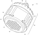
도 2를 참조하면, 조명 시스템(10)의 일 실시예의 사시도가 도시되었다. 일 실시예에서, 조명 시스템(10)은 종래의 스크류-인(screw-in) 베이스(에디슨 베이스)(30)를 포함하며, 이는 전기적 그리드에 체결되는 종래의 소켓에 연결될 수 있다. 시스템 구성요소들은 일반적으로 하우징 구조체(32)로 언급되는 하우징 구조체에 포함된다. 도 3에 관해 추가로 설명 및 도시되는 바와 같이, 하우징 구조체(32)는 광원(12)의 내측 부분, 열 관리 시스템(14) 및 드라이버 전자장치(16)를 지지하고 보호하도록 구성된다.2, a perspective view of one embodiment of a
일 실시예에서, 하우징 구조체(32)는 공기 슬롯(36)이 관통되어있는 케이지(34)를 포함한다. 케이지(34)는 드라이버 전자장치(16)가 위에 배치된 전자장치 기판을 보호하도록 구성된다. 하우징 구조체(32)는 열 관리 시스템(14)의 구성요소를 보호하기 위해 열 관리 시스템 하우징(38)을 더 포함한다. 열 관리 시스템 하우징(38)은 공기 슬롯(39)을 포함한다. 일 실시예에 따르면, 열 관리 시스템 하우징(38)은, 하기 설명된 바와 같이, 공기 포트(22)가 열 관리 시스템(14) 내의 합성 제트에 의해 주변 공기를 조명 시스템(10) 안팎으로 유동할 수 있도록 형성되어있다. 추가로, 하우징 구조체(32)는 광원(12)을 지지 및 보호하도록 구성된 면판(faceplate)(40)을 포함한다. 도 3에 설명 및 도시되는 바와 같이, 면판(40)은 개구부를 포함하는데, 이 개구부는 광원(12)의 LED(42)의 면 및/또는 광원(12)의 렌즈(optic)가 조명 시스템(10)의 아랫면에 노출되도록 허용하기 위한 크기 및 형태로 되며, 그 결과 빛을 비추었을 때, LED(42)는 일반 공간 다운라이팅을 제공한다. 도 4를 참조하여 도시 및 설명된 변형 실시예에서, 하우징 구조체는 또한 면판(40)을 둘러싸는 외장 피스를 포함하며, 이 피스는 특정 장식적 속성을 제공할 뿐만 아니라 추가적인 열 전달을 제공하여 조명 시스템(10)을 냉각한다. 도 4를 참조하여 후술하는 실시예에 도시된 바와 같이, 열 관리 시스템 하우징(38)의 형태는 다양할 수 있다.In one embodiment, the
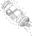
도 3으로 돌아가서, 조명 시스템(10)의 분해도가 도시된다. 상기 설명 및 도시된 바와 같이, 조명 시스템(10)은 하우징 구조체(32)를 포함하며, 이 하우징 구조체(32)는 케이지(34), 열 관리 시스템 하우징(38) 및 면판(40)을 포함한다. 조립시에, 하우징 구조체(32)는 케이지(34), 열 관리 시스템 하우징(38), 및 복수의 너트(도시하지 않음)와 같은 고정 메커니즘을 결합하도록 구성된 나사(44)에 의해 고정된다. 일 실시예에서, 면판(40)은 조명 시스템(10)의 베이스를 마찰식으로 결합하는 크기로 되고 형성되며 및/또는 추가적인 나사(도시하지 않음)와 같은 또 다른 체결 메커니즘에 의해 고정된다. 면판(40)의 개구부(48)는, 광원(12)의 아랫면 상에 위치한 LED(42)가 개구부(48)로 보일 수 있도록 크기로 되고 형성된다. 또한, 광원(12)은 열 관리 시스템(14)의 아랫면을 결합하도록 구성된 핀(50)과 같은 체결 구성요소들을 포함한다. 이해될 수 있는 바와 같이, 다양한 체결 메카니즘이 포함되어 조명 시스템(10)의 구성요소들을 하우징 구조체(32) 내에 고정시키며, 조명 시스템(10)은 사용을 위해 일단 조립되면 단일 유닛이다.3, an exploded view of the
진술한 바와 같이, 케이지(34) 내에 수용되는 드라이버 전자장치(16)는 프린트 회로 기판(PCB)(54)과 같은 단일 기판 상에 장착된 다수의 집적 회로 구성요소(52)를 다수 포함한다. 이해할 수 있는 바와 같이, 집적 회로 구성요소(52)와 같은 구성요소가 장착되어있는 PCB(54)는, 프린트 회로 어셈블리(printed circuit assembly; PCA)를 형성한다. 통상적으로, PCB(54)는 보호 케이지(34) 내에 끼워맞추는 크기로 되고 형성된다. 추가로, PCB(54)는, 드라이버 전자장치(16), 열 관리 시스템 하우징(38) 및 케이지(34)를 기계적으로 함께 결합하기 위한 나사(44)를 수용하도록 구성된 관통 구멍(56)을 포함한다. 도시된 실시예에 따르면, 열 관리 시스템(14) 뿐만 아니라 광원(12)에 필요한 전력을 공급하도록 구성된 모든 전자장치들은 단일 PCB(54) 상에 수용되어 있고, 이 기판(54)은 열 관리 시스템(14) 및 광원(12) 위에 위치되어 있다. 따라서, 현 설계에 따르면, 광원(12) 및 열 관리 시스템(14)은 동일한 입력 전력을 공유한다.As stated, the
도시된 실시예에서, 열 관리 시스템(14)은 나사(62)를 통해 베이스(60)에 체결된 다수의 핀(58)을 갖는 히트 싱크(20)를 포함한다. 이해할 수 있는 바와 같이, 히트 싱크(20)는 LED(42)에 의해 생성된 열을 소산시키기 위한 열-전도 경로를 제공한다. 히트 싱크(20)의 베이스(60)는, LED(42)로부터의 열이 히트 싱크(20)의 베이스(60)로 전달될 수 있도록, 광원(12)의 후면부에 대해 배치된다. 핀(58)은 베이스(60)로부터 수직으로 연장하며, 이들은 서로 평행하게 배열된다.In the illustrated embodiment, the
열 관리 시스템(14)은 다수의 합성 제트 장치(18)를 더 포함하는데, 이 합성 제트 장치(18)는 히트 싱크(20)의 핀(58)에 인접하게 배열된다. 이해될 수 있는 바와 같이, 각각의 합성 제트 장치(18)는 LED의 추가 냉각을 제공하도록 면판(40)을 가로질러 그리고 핀(58) 사이에 합성 제트 기류를 제공하도록 구성된다. 각각의 합성 제트 장치(18)는 합성 제트 전력 공급장치(26)에 의해 구동되도록 구성된 다이아프램(64)을 포함하며, 이 다이아프램(64)은 중공 프레임(66) 내에서 전후로 신속하게 이동하여 프레임(66)의 개구부를 통해 공기 제트를 형성하고, 이 공기 제트는 히트 싱크(20)의 핀(58) 사이의 갭을 통해 배향된다.The
도 4와 관련하여 보다 상세하게 설명하는 바와 같이, 열 관리 시스템 하우징(38)은 하우징 구조체에 몰드형 슬롯을 포함하며, 이 슬롯은 합성 제트 장치(18)를 2개의 접점에서 결합하도록 구성된다. 열 관리 시스템 하우징(38) 내에 몰드형 슬롯을 제공함으로써, 합성 제트 장치(18)는 하우징(38) 내에 정확하게 위치될 수 있다. 열 관리 시스템 하우징(38) 내에 합성 제트 장치(18)를 더 고정하기 위해, 브릿지(68)가 제공될 수 있다. 브릿지(68)는 각각의 합성 제트 장치(18)를 1개의 접점에서 결합하도록 구성된다. 따라서, 현재 실시예에서, 일단 조립되면, 각각의 합성 제트 장치(18)는 조명 시스템(10) 내에 3개의 접점에서 고정된다.As described in more detail with respect to FIG. 4, the thermal
열 관리 시스템(14) 및 이러한 합성 제트 장치(18)에 의해 생성된 단방향 기류는 도 4에 관하여 후술될 것이다. 도 3의 열 관리 시스템 하우징(38)은 케이지(34)의 에지(edge)를 지나 연장되는 구부러진(bowed) 측면을 포함하여, 덕트(22)를 통한 공기 흐름용의 증가된 개구부를 제공하지만, 특정 실시예에서는 이러한 구부러진 설계가 제외될 수 있다는 것이 이해되어야 한다. 예를 들어, 도 4를 참조하여 도시된 바와 같이, 덕트(22)의 크기는, 열 관리 시스템 하우징(38)의 측면이 케이지(34)의 에지로부터 선형으로 연장하여 일정한 구조를 마련하도록 감소될 수 있다. 슬롯(39)은 조명 시스템(10)을 통해 충분한 공기 흐름을 제공하여 덕트(22)의 크기의 감소를 허용하도록 설계될 수 있다.The
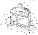
이제 도 4를 참고하면, 조명 시스템(10)의 부분 단면도가 제공되어, 상술한 열 관리 시스템 하우징(38)의 변형 실시예가 도시될 뿐만 아니라 열 관리 시스템(14)의 특정 상세사항도 도시된다. 전술한 바와 같이, 열 관리 시스템(14)은 열 관리 시스템 하우징(38) 내에 합성 제트 장치(18), 히트 싱크(20), 공기 포트(22) 및 슬롯(39)을 포함한다. 히트 싱크(20)의 베이스(60)는 아래에 위치한 광원(12)과 접촉하여 배열되며, 그 결과 열이 LED(42)로부터 히트 싱크(20)로 수동적으로 전달된다. 합성 제트 장치의 어레이는 히트 싱크(20)의 핀(58)을 따라서 열전달의 선형 전달에 능동적으로 도움을 주도록 배치된다. 변형 실시예에서, 각 합성 제트 장치(18)는 평행한 핀(58) 사이의 갭에 의해 제공된 리세스 사이에 위치되며, 각각의 합성 제트 장치(18)에 의해 생성된 공기 스트림이 평행한 핀(58) 사이의 갭을 통해 유동한다. 합성 제트 장치(18)는 핀(58)사이의 히트 싱크(20)를 통과하는 공기의 단방향 흐름을 생성하기 위한 동력을 공급할 수 있고, 그 결과 주변 지역으로부터의 공기는 열 관리 시스템 하우징(38)의 하나의 측면 상에 있는 포트(22A) 및 슬롯(39A) 중 하나를 통해 덕트로 유입되며, 히트 싱크(20)로부터의 따뜻한 공기는 열 관리 시스템 하우징(38)의 다른 측면 상에 있는 다른 포트(22B) 및 슬롯(39B)을 통해 주변 공기로 분사된다. 핀 갭을 통해 포트(22A) 및 슬롯(39A)으로 들어가서 포트(22B) 및 슬롯(39B)으로 나온 단방향의 기류는 일반적으로 기류 화살표(70)에 의해 표시된다. 바람직하게, 단방향의 기류(70)는 조명 시스템(10) 내의 열 축적을 방지하며, 이는 다운라이트 시스템의 열 관리의 설계에서의 관심사를 야기한다. 변형 실시예에서, 합성 제트 장치(18)에 의해 생성된 공기 흐름은 예를 들면 방사상 또는 충돌할 수 있다. 게다가, 열 관리 시스템은 외장 판(73)을 더 포함할 수 있다. 외장 판(73)은 전도성일 수 있으며, 히트 싱크(20)에 직접적으로 결합되어 조명 시스템(10)으로부터의 열 전달을 주변 공기에 방사상으로 더 제공할 수 있다. 현재 설명되는 열 관리 시스템(14)은 대략 30W의 열 발생시 100℃ 미만의 LED 접합 온도를 제공할 수 있는 능력을 갖추고 있다.Referring now to FIG. 4, a partial cross-sectional view of the
이해할 수 있는 바와 같이, 합성 제트 장치(18)와 같은 합성 제트는 가요성 구조체 및 공기가 통과할 수 있는 소형 오리피스로 둘러싸인 공기의 캐비티 또는 용적을 포함하는 낭비없는 매스플로우(zero-net-massflow) 장치이다. 구조체는 오리피스를 통한 공기의 대응 흡입 및 방출을 야기하는 주기적 양태로 변형하도록 유도된다. 합성 제트 장치(18)는 외부 유동, 여기서는 주변 공기로 순 양(net positive)의 운동량을 전달한다. 각각의 사이클 동안, 이 운동량은 제트 오리피스로부터 나오는 자체-대류 와류 쌍극자로서 나타난다. 다음에, 와류 쌍극자는 냉각될 표면, 여기에서 하부 광원(12)에 충돌하고, 경계층을 교란시키고, 그 공급원으로부터의 열을 대류시킨다. 정상 상태 조건에서, 이러한 충돌 메커니즘은 가열된 구성요소 근방에서 순환 패턴을 발생시키고, 고온 공기와 주변 유체 사이에서 혼합을 촉진시킨다.As can be appreciated, a synthetic jet, such as
일 실시예에 따르면, 각각의 합성 제트 장치(18)는 2개의 압전 디스크를 가지며, 위상을 벗어나 여기되고, 오리피스를 갖는 얇고 유연한 벽에 의해 분리된다. 이러한 특정 설계는 테스트 동안에 상당한 냉각 증진을 입증하여 왔다. 합성 제트 작동 조건은 조명 분야에서 실행상으로 선택되어져야 한다는 것이 이해되어야 한다. 압전 소자는 압전 버저 요소와 유사하다. 합성 제트 장치(18)의 냉각 성능 및 작동 특성은 작동에 사용되는 압전 물질 내의 전기기계적 결합, 압전 작동에 대한 가요성 디스크의 기계적 응답을 위한 구조적 동역학, 그리고 제트의 공기 유동(70)을 위한 유체 동역학 및 열 전달을 포함하는 다양한 물리학적 영역 사이의 상호작용에서 기인한다. 정교한 유한 요소(finite element; FE) 및 전산 유체 동역학(computational fluid dynamics; CFD) 소프트웨어 프로그램은 합성 제트 설계 및 최적화를 위해 연관된 물리학을 시뮬레이션하는데 종종 사용된다.According to one embodiment, each
조명 시스템(10) 내에 합성 제트 장치(18)를 유지하는 패키지는 합성 제트의 움직임을 기계적으로 제한하지 않는 최대 냉각 효과를 위해 합성 제트 장치(18)를 배향시켜야만 한다. 바람직하게, 합성 제트 장치(18)는 접점 부착 기술을 활용하는 조명 시스템(10) 내에 고정된다. 도 5를 참고하여 더 명확하게 도시된 바와 같이, 각각의 합성 제트 장치(18)는 접점(72)에 의해 제 위치에 유지된다. 도시된 실시예에서, 열 관리 시스템 하우징(38) 또는 브릿지(68)와 같은, 합성 제트 장치(18)가 조명 시스템의 구조에 고정되는 곳은 3개의 접점이 있다. 접촉 지역을 최소화함으로써, 합성 제트 장치가 조명 시스템(10) 내에서 불필요하게 제한받지 않는다.The package holding the
도 5를 참고하면, 조명 시스템(10)의 일부분의 개략도가 도시되어 본 발명의 실시예에 따라, 조명 시스템(10) 내에 합성 제트 장치(18)를 고정하는데 사용되는 접점 부착 기술을 도시한다. 도시된 바와 같이, 열 관리 시스템 하우징(38)은 베이스 브라켓(74)을 포함한다. 도시된 실시예에서, 베이스 브라켓(74)은 열 관리 시스템 하우징(38)의 몰드형 부분이다. 그러나, 변형 실시예에서, 베이스 브라켓(74)은 별개의 피스일 수 있다. 베이스 브라켓(74)은 합성 제트 장치(18)를 확실하게 수용하도록 구성된 베이스 슬롯(76)을 포함한다. 특히, 베이스 브라켓(74)은 각각의 합성 제트 장치(18)를 결합하기 위해 2개의 베이스 슬롯(76)을 포함한다. 도시된 실시예에서, 베이스 브라켓(74)은 6개의 합성 제트 장치(18)를 수용하도록 구성된다. 조립 중에, 합성 제트 장치(18)는 베이스 슬롯(76) 안으로 들어간다. 일 실시예에서, 베이스 슬롯(76)은 합성 제트 장치(18)를 제자리로 안내하는 것을 돕도록 테이퍼형 에지를 갖는다. 베이스 슬롯(76)은 각각의 베이스 슬롯(76)의 바닥에서 합성 제트 장치(18)의 두께보다 약간 넓을 뿐이다. 또한, 베이스 슬롯은 단지 합성 제트 장치가 완전히 구동되는 능력에 영향을 두지 않고 합성 제트 장치(18)가 제자리에 있도록 억제하기에 충분히 깊다. 유리하게, 각각의 베이스 슬롯(76)이 베이스 브라켓(74)으로 성형되고, 이는 도시된 바와 같이 다시 열 관리 시스템 하우징(38)으로 성형될 수 있기 때문에, 합성 제트 장치(18) 각각의 위치 설정은 히트 싱크(20)에 대해 정확하게 규정되어 최대의 냉각을 제공한다.Referring to FIG. 5, a schematic diagram of a portion of a
일단 합성 제트 장치(18)가 베이스 슬롯(76) 내에 위치하게 되면, 브릿지(68)가 하우징(38) 안의 슬롯(78)에 끼워질 수 있다. 이해할 수 있는 바와 같이, 브릿지(68)는, 이 브릿지가 하우징에 기계적으로 체결되도록 허용하는 스내핑(snapping) 메커니즘(도시하지 않음)을 포함한다. 브릿지(68)는 다수의 브릿지 슬롯(80)을 포함한다. 각각의 브릿지 슬롯(80)은 합성 제트 장치(18)와 제 3 접점(72)에서 결합하도록 테이퍼져서 위치된다. 따라서, 브릿지(68)는 각각의 합성 제트 장치(18)가 조명 시스템(10) 내에 안전하게 고정하기 위한 고정 메커니즘을 제공하며, 그 결과 작동 중의 진동, 또는 조명 시스템(10)의 다른 움직임은 합성 제트 장치(18)를 느슨하게 하지 않는다. 유리하게, 브릿지(68)는 합성 제트 장치(68)의 전체 세트를 제자리에 고정하도록 이용된 단일 구조체이다. 브릿지(68)에 단일 재료 사용은 합성 제트 장치(18)를 베이스 브라켓(74)에 고정하는 간단한, 반복가능한, 튼튼한, 쉽게 제작이 가능한 그리고 비용 효과적인 방법이다. 추가로, 접점 부착 기술을 활용함으로써, 여기에 설명된 바와 같이, 추가적인 구동 전력의 요구 없이, 그리고 소음의 큰 증가 없이 향상된 냉각 효율을 제공한다.Once the
추가로, 실리콘(도시하지 않음)과 같은 연질 겔이 3개 접점(72) 각각에 도포되어 진동 소음을 감소시키고 조명 시스템(10) 내 각각의 합성 제트 장치(18)를 더 부착시키며, 그 결과 합성 제트 장치(18)는 슬롯(76, 80) 내에서 추가로 고정된다. 추가로, 슬롯에 끼워진 베이스 브라켓(74) 및 슬롯에 끼워진 브릿지(68)와 함께 장착된 겔을 사용함으로써, 고정에 요구되는 힘을 감소시킬 수 있다.In addition, a soft gel such as silicone (not shown) is applied to each of the three
기재된 설명은 예시를 사용하여, 본 발명을 개시하고, 최적의 형태를 포함하며, 또한 본 기술 분야에 숙련된 자들이 본 발명을 수행하는 것이 가능하도록 하고, 이는 어떠한 장치 또는 시스템을 제작 및 사용하는 것과 어떤 포함된 방법을 수행하는 것을 포함한다. 드라이버 전자장치 및 광원에 대한 추가적인 상세설명은 제너럴 일렉트릭 캄파니에게 양도된 발명의 명칭이 "열 관리 시스템을 구비한 조명 시스템"인 2010년 2월 23일자로 출원된 미국 특허 출원 제 12/711,000호에 기재되어 있으며, 여기에 참고로 인용된다. 본 발명의 특허 가능한 영역은 특허청구범위에 의해 규정되며, 본 기술 분야에 숙련된 자들에 의해 이루어질 수 있는 다른 예시들을 포함한다. 이러한 다른 예시들은, 만약 그들이 청구항의 일반적인 언어와 다르지 않은 구조적 요소를 가지거나, 또는 그들이 청구항의 일반적인 언어와 미약한 차이를 가지는 등가의 구조적 요소를 포함한다면, 그 예시들이 청구항의 범위 내에 있다고 의도될 수 있다.The written description uses examples to disclose the invention, to include the best mode, and to enable any person skilled in the art to practice the invention, which can be used to make and use any apparatus or system. And performing any included method. Further details of the driver electronics and light source can be found in US Patent Application No. 12 / 711,000, filed Feb. 23, 2010, entitled "Lighting Systems with Thermal Management System," assigned to General Electric Company. And incorporated herein by reference. The patentable scope of the invention is defined by the claims, and includes other examples that can be made by those skilled in the art. Such other examples may be intended to be within the scope of the claims if they have structural elements that do not differ from the general language of the claims, or if they include equivalent structural elements with slight differences from the general language of the claims. Can be.
Claims (29)
하우징 구조체와,
상기 하우징 구조체 내의 개구부를 통해 볼 수 있는 조명을 제공하도록 구성된 광원과,
상기 조명 시스템을 냉각하도록 구성되고 그리고 복수의 접점에 의해 상기 하우징 구조체 내에 고정된 복수의 합성 제트 장치(a plurality of synthetic jet devices)를 포함하는 열 관리 시스템(thermal management system)과,
상기 광원 및 상기 열 관리 시스템의 각각에 전력을 공급하도록 구성된 드라이버 전자장치(driver electronics)를 포함하는
조명 시스템.In a lighting system,
Housing structure,
A light source configured to provide illumination visible through an opening in the housing structure;
A thermal management system configured to cool the lighting system and including a plurality of synthetic jet devices secured in the housing structure by a plurality of contacts;
Driver electronics configured to power each of the light source and the thermal management system.
Lighting system.
상기 광원은 적어도 하나의 발광 다이오드(light emitting diode; LED)를 포함하는
조명 시스템.The method of claim 1,
The light source includes at least one light emitting diode (LED).
Lighting system.
상기 열 관리 시스템은 히트 싱크를 포함하고,
상기 히트 싱크는 베이스 부분과, 상기 베이스 부분으로부터 연장되는 복수의 핀(fin)을 포함하며,
상기 복수의 핀은 이들 핀 사이에 복수의 공기 갭을 제공하는
조명 시스템.The method of claim 1,
The thermal management system includes a heat sink,
The heat sink includes a base portion and a plurality of fins extending from the base portion,
The plurality of fins provide a plurality of air gaps between these fins.
Lighting system.
상기 복수의 합성 제트 장치의 각각은 복수의 핀의 각각 사이에서 각 공기 갭 중 하나를 통해 단방향 공기 흐름 경로를 생성하도록 배열되어 있는
조명 시스템.The method of claim 3, wherein
Each of the plurality of composite jet devices is arranged to create a unidirectional air flow path through one of each air gap between each of the plurality of fins.
Lighting system.
상기 열 관리 시스템은, 상기 복수의 합성 제트 장치가 작동될 때, 상기 조명 시스템을 통한 주변 공기의 유입 및 유출을 제공하기 위한 공기 포트를 포함하는
조명 시스템.The method of claim 1,
The thermal management system includes an air port for providing inflow and outflow of ambient air through the illumination system when the plurality of synthetic jet devices are operated.
Lighting system.
상기 열 관리 시스템은, 상기 복수의 합성 제트 장치가 작동될 때, 상기 조명 시스템을 통한 주변 공기의 유입 및 유출을 제공하기 위한 슬롯을 상기 하우징 구조체 내에 포함하고 있는
조명 시스템.The method of claim 1,
The thermal management system includes a slot in the housing structure for providing inlet and outlet of ambient air through the illumination system when the plurality of synthetic jet devices are operated.
Lighting system.
상기 복수의 합성 제트 장치의 각각을 2개의 각 접점에서 유지하도록 구성된 베이스 브라켓을 더 포함하는
조명 시스템.The method of claim 1,
A base bracket configured to hold each of the plurality of composite jet devices at two respective contacts;
Lighting system.
상기 하우징 구조체는 상기 베이스 브라켓이 내부에 성형되어 있는 몰드형 구조체인
조명 시스템.The method of claim 7, wherein
The housing structure is a mold structure in which the base bracket is molded therein.
Lighting system.
2개의 접점의 각각은 테이퍼형 에지를 갖는 슬롯을 포함하는
조명 시스템.The method of claim 7, wherein
Each of the two contacts comprises a slot having a tapered edge
Lighting system.
상기 하우징 구조체에 결합하도록 구성되고, 또한 복수의 합성 제트 장치 각각을 상기 하우징 구조체 내에 유지하도록 구성된 브릿지를 더 포함하는
조명 시스템.The method of claim 1,
A bridge configured to couple to the housing structure, the bridge further configured to retain each of the plurality of composite jet devices in the housing structure;
Lighting system.
상기 브릿지는 복수의 슬롯을 포함하며, 각각의 슬롯은 복수의 합성 제트 장치의 각각 하나를 유지하도록 구성된
조명 시스템.11. The method of claim 10,
The bridge includes a plurality of slots, each slot configured to hold each one of the plurality of composite jet devices.
Lighting system.
상기 복수의 슬롯의 각각은 테이퍼형 에지를 포함하는
조명 시스템.The method of claim 11,
Each of the plurality of slots includes a tapered edge
Lighting system.
상기 드라이버 전자장치는 발광 다이오드(LED) 전력 공급장치 및 합성 제트 전력 공급장치를 포함하는
조명 시스템. The method of claim 1,
The driver electronics includes a light emitting diode (LED) power supply and a composite jet power supply.
Lighting system.
상기 조명 시스템은 상기 조명 시스템을 표준 소켓에 전기적으로 결합하도록 구성된 나사-기반 구조체를 포함하는
조명 시스템.The method of claim 1,
The lighting system includes a screw-based structure configured to electrically couple the lighting system to a standard socket.
Lighting system.
상기 조명 시스템은 적어도 대략 1500루멘을 생산하도록 구성된
조명 시스템.The method of claim 1,
The lighting system is configured to produce at least approximately 1500 lumens
Lighting system.
상기 복수의 합성 제트 장치는 3개의 접점에 의해 상기 하우징 구조체 내에 고정되는
조명 시스템.The method of claim 1,
The plurality of composite jet devices are fixed in the housing structure by three contacts.
Lighting system.
조명판의 표면에 배치되는 발광 다이오드(LED)의 어레이와,
LED의 어레이 위에 배치된 열 관리 시스템을 포함하며,
상기 열 관리 시스템은,
베이스와, 이 베이스로부터 연장되는 복수의 핀을 구비하는 히트 싱크와,
복수의 합성 제트 장치로서, 상기 복수의 합성 제트 장치의 각각은 상기 복수의 핀의 각 쌍 사이에 제트 스트림을 생성하도록 배치되며, 상기 복수의 합성 제트 장치는 복수의 접점에서 상기 조명 시스템에 결합되어 있는, 상기 복수의 합성 제트 장치를 포함하는
조명 시스템.In a lighting system,
An array of light emitting diodes (LEDs) disposed on the surface of the lighting plate;
A thermal management system disposed over the array of LEDs,
The thermal management system,
A heat sink having a base and a plurality of fins extending from the base,
A plurality of composite jet apparatuses, each of the plurality of composite jet apparatuses arranged to generate a jet stream between each pair of the plurality of fins, the plurality of composite jet apparatuses being coupled to the lighting system at a plurality of contacts. Which includes the plurality of synthetic jet devices
Lighting system.
상기 조명 시스템은 상기 복수의 합성 제트 장치를 그 사이에 유지하도록 구성된 베이스 브라켓과 브릿지를 포함하는
조명 시스템.The method of claim 17,
The lighting system includes a base bracket and a bridge configured to hold the plurality of composite jet devices therebetween.
Lighting system.
상기 베이스 브라켓은 복수의 슬롯을 포함하며,
상기 복수의 슬롯의 각각은 상기 복수의 합성 제트 장치 중 하나를 수용하도록 구성되어 있는
조명 시스템.The method of claim 18,
The base bracket includes a plurality of slots,
Each of the plurality of slots is configured to receive one of the plurality of synthetic jet devices
Lighting system.
상기 브릿지는 복수의 슬롯을 포함하고,
상기 복수의 슬롯의 각각은 상기 복수의 합성 제트 장치 중 하나를 수용하도록 구성되어 있는
조명 시스템.The method of claim 18,
The bridge includes a plurality of slots,
Each of the plurality of slots is configured to receive one of the plurality of synthetic jet devices
Lighting system.
상기 복수의 합성 제트 장치는 3개의 접점에서 상기 조명 시스템에 결합되어 있는
조명 시스템.The method of claim 17,
The plurality of composite jet devices are coupled to the lighting system at three contacts.
Lighting system.
상기 열 관리 시스템은 슬롯을 내부에 구비하는 열 관리 시스템 하우징을 포함하며,
상기 슬롯은, 상기 복수의 합성 제트가 작동될 때, 상기 조명 시스템의 내외로 주변 공기가 흐를 수 있게 허용하도록 구성되어 있는
조명 시스템.The method of claim 17,
The thermal management system includes a thermal management system housing having a slot therein;
The slot is configured to allow ambient air to flow in and out of the lighting system when the plurality of synthetic jets are operated.
Lighting system.
광원과,
복수의 슬롯을 포함하는 하우징 구조체와,
복수의 합성 제트 장치를 포함하며,
상기 복수의 합성 제트 장치 각각은 상기 복수의 슬롯 중 적어도 하나와 결합하도록 구성되어 있는
조명 시스템.In a lighting system,
A light source,
A housing structure comprising a plurality of slots,
A plurality of synthetic jet devices,
Each of the plurality of synthetic jet devices configured to engage with at least one of the plurality of slots.
Lighting system.
상기 복수의 합성 제트 장치의 각각은 각 접점에서 상기 복수의 슬롯 중 2개와 결합하도록 구성되어 있는
조명 시스템.24. The method of claim 23,
Each of the plurality of composite jet devices is configured to engage two of the plurality of slots at each contact point
Lighting system.
상기 하우징 구조체는 베이스 브라켓을 포함하고,
상기 베이스 브라켓은 복수의 슬롯을 포함하는
조명 시스템.24. The method of claim 23,
The housing structure comprises a base bracket,
The base bracket includes a plurality of slots
Lighting system.
상기 베이스 브라켓은 몰드형 구조체이며,
상기 하우징 구조체는 상기 베이스 브라켓이 내부에 성형되어 있는
조명 시스템.The method of claim 25,
The base bracket is a mold structure,
The housing structure is formed in the base bracket therein
Lighting system.
상기 베이스 브라켓에 대해 상기 합성 제트 장치의 반대측에서 상기 복수의 합성 제트 장치의 각각에 결합하도록 구성된 브릿지를 더 포함하는
조명 시스템.24. The method of claim 23,
And a bridge configured to couple to each of the plurality of composite jet apparatuses on the opposite side of the composite jet apparatus relative to the base bracket.
Lighting system.
상기 조명 시스템은 상기 복수의 합성 제트 장치에 인접하고 평행하게 배치되지만 직접 접촉하지는 않는 복수의 핀을 갖는 히트 싱크를 더 포함하는
조명 시스템.24. The method of claim 23,
The lighting system further includes a heat sink having a plurality of fins disposed adjacent to and parallel to the plurality of synthetic jet devices but not in direct contact.
Lighting system.
상기 복수의 슬롯의 각각은 접착성 겔을 내부에 포함하고 있는
조명 시스템.24. The method of claim 23,
Each of the plurality of slots contains an adhesive gel therein;
Lighting system.
Applications Claiming Priority (3)
| Application Number | Priority Date | Filing Date | Title |
|---|---|---|---|
| US12/908,948 US8602607B2 (en) | 2010-10-21 | 2010-10-21 | Lighting system with thermal management system having point contact synthetic jets |
| US12/908,948 | 2010-10-21 | ||
| PCT/US2011/045460 WO2012054115A1 (en) | 2010-10-21 | 2011-07-27 | Lighting system with thermal management system having point contact synthetic jets |
Publications (1)
| Publication Number | Publication Date |
|---|---|
| KR20130124311A true KR20130124311A (en) | 2013-11-13 |
Family
ID=44773129
Family Applications (1)
| Application Number | Title | Priority Date | Filing Date |
|---|---|---|---|
| KR1020137010063A KR20130124311A (en) | 2010-10-21 | 2011-07-27 | Lighting system with thermal management system having point contact synthetic jets |
Country Status (8)
| Country | Link |
|---|---|
| US (3) | US8602607B2 (en) |
| EP (1) | EP2630409A1 (en) |
| JP (1) | JP5879355B2 (en) |
| KR (1) | KR20130124311A (en) |
| CN (1) | CN103154608B (en) |
| BR (1) | BR112013008809A2 (en) |
| MX (1) | MX2013004430A (en) |
| WO (1) | WO2012054115A1 (en) |
Families Citing this family (29)
| Publication number | Priority date | Publication date | Assignee | Title |
|---|---|---|---|---|
| US10340424B2 (en) | 2002-08-30 | 2019-07-02 | GE Lighting Solutions, LLC | Light emitting diode component |
| US8593040B2 (en) | 2009-10-02 | 2013-11-26 | Ge Lighting Solutions Llc | LED lamp with surface area enhancing fins |
| US10309627B2 (en) | 2012-11-08 | 2019-06-04 | Cree, Inc. | Light fixture retrofit kit with integrated light bar |
| US9822951B2 (en) | 2010-12-06 | 2017-11-21 | Cree, Inc. | LED retrofit lens for fluorescent tube |
| KR101227522B1 (en) * | 2011-05-25 | 2013-01-31 | 엘지전자 주식회사 | Lighting apparatus |
| US9488324B2 (en) | 2011-09-02 | 2016-11-08 | Soraa, Inc. | Accessories for LED lamp systems |
| US9587820B2 (en) | 2012-05-04 | 2017-03-07 | GE Lighting Solutions, LLC | Active cooling device |
| US9500355B2 (en) * | 2012-05-04 | 2016-11-22 | GE Lighting Solutions, LLC | Lamp with light emitting elements surrounding active cooling device |
| US9194575B2 (en) | 2012-06-29 | 2015-11-24 | General Electric Company | Thermal management in optical and electronic devices |
| US9482396B2 (en) | 2012-11-08 | 2016-11-01 | Cree, Inc. | Integrated linear light engine |
| US9441818B2 (en) | 2012-11-08 | 2016-09-13 | Cree, Inc. | Uplight with suspended fixture |
| US10788176B2 (en) | 2013-02-08 | 2020-09-29 | Ideal Industries Lighting Llc | Modular LED lighting system |
| US9494304B2 (en) | 2012-11-08 | 2016-11-15 | Cree, Inc. | Recessed light fixture retrofit kit |
| CN105188949B (en) | 2013-03-14 | 2018-10-02 | 通用电气公司 | Synthesizing jet-flow suspended structure |
| US10584860B2 (en) | 2013-03-14 | 2020-03-10 | Ideal Industries, Llc | Linear light fixture with interchangeable light engine unit |
| US9874333B2 (en) | 2013-03-14 | 2018-01-23 | Cree, Inc. | Surface ambient wrap light fixture |
| CN105026050A (en) | 2013-03-14 | 2015-11-04 | 通用电气公司 | Low resonance acoustic synthetic jet structure |
| US9461024B2 (en) | 2013-08-01 | 2016-10-04 | Cree, Inc. | Light emitter devices and methods for light emitting diode (LED) chips |
| US10900653B2 (en) * | 2013-11-01 | 2021-01-26 | Cree Hong Kong Limited | LED mini-linear light engine |
| US10612747B2 (en) | 2013-12-16 | 2020-04-07 | Ideal Industries Lighting Llc | Linear shelf light fixture with gap filler elements |
| US10100988B2 (en) | 2013-12-16 | 2018-10-16 | Cree, Inc. | Linear shelf light fixture with reflectors |
| USD757324S1 (en) | 2014-04-14 | 2016-05-24 | Cree, Inc. | Linear shelf light fixture with reflectors |
| US10085363B2 (en) * | 2014-05-22 | 2018-09-25 | General Electric Company | Integrated compact impingement on extended heat surface |
| US9879661B2 (en) | 2014-08-29 | 2018-01-30 | General Electric Company | Vibrational fluid mover jet with active damping mechanism |
| CN104296100B (en) * | 2014-10-14 | 2017-02-15 | 东莞市闻誉实业有限公司 | Led lamp |
| USD863607S1 (en) * | 2015-07-07 | 2019-10-15 | Auroralight, Inc. | Ball and socket heat exchanger for a light fixture |
| WO2017099677A1 (en) * | 2015-12-09 | 2017-06-15 | Ozyegin Universitesi | Heat sink cooling with preferred synthetic jet cooling devices |
| DE102016000812A1 (en) | 2016-01-26 | 2017-07-27 | Audi Ag | Electrical arrangement for a motor vehicle, motor vehicle and method for operating a synthetic jet |
| KR101733061B1 (en) * | 2016-02-02 | 2017-05-08 | 대성쎌틱에너시스 주식회사 | Turn Down Ratio Damper |
Family Cites Families (62)
| Publication number | Priority date | Publication date | Assignee | Title |
|---|---|---|---|---|
| US6123145A (en) | 1995-06-12 | 2000-09-26 | Georgia Tech Research Corporation | Synthetic jet actuators for cooling heated bodies and environments |
| US5758823A (en) | 1995-06-12 | 1998-06-02 | Georgia Tech Research Corporation | Synthetic jet actuator and applications thereof |
| US6247525B1 (en) | 1997-03-20 | 2001-06-19 | Georgia Tech Research Corporation | Vibration induced atomizers |
| US6109222A (en) | 1997-11-24 | 2000-08-29 | Georgia Tech Research Corporation | Miniature reciprocating combustion-driven machinery |
| US6412732B1 (en) | 1999-07-06 | 2002-07-02 | Georgia Tech Research Corporation | Apparatus and method for enhancement of aerodynamic performance by using pulse excitation control |
| AU2001229632A1 (en) * | 2000-01-14 | 2001-07-24 | Design Rite Llc | Circuit for driving light-emitting diodes |
| US6359392B1 (en) * | 2001-01-04 | 2002-03-19 | Motorola, Inc. | High efficiency LED driver |
| WO2002072421A2 (en) | 2001-03-10 | 2002-09-19 | Georgia Tech Research Corporation | Modification of fluid flow about bodies and surfaces through virtual aero-shaping of airfoils with synthetic jet actuators |
| US6874911B2 (en) * | 2002-04-09 | 2005-04-05 | Ccs, Inc. | Light irradiating unit, lighting unit and method for manufacturing lighting unit |
| US6588497B1 (en) | 2002-04-19 | 2003-07-08 | Georgia Tech Research Corporation | System and method for thermal management by synthetic jet ejector channel cooling techniques |
| JP4298746B2 (en) | 2003-02-20 | 2009-07-22 | コーニンクレッカ フィリップス エレクトロニクス エヌ ヴィ | Cooling assembly with micro jet |
| US7204615B2 (en) | 2003-03-31 | 2007-04-17 | Lumination Llc | LED light with active cooling |
| US7556406B2 (en) * | 2003-03-31 | 2009-07-07 | Lumination Llc | Led light with active cooling |
| US7543961B2 (en) | 2003-03-31 | 2009-06-09 | Lumination Llc | LED light with active cooling |
| CN1802533B (en) | 2003-05-05 | 2010-11-24 | 吉尔科有限公司 | LED-based light bulb |
| KR200350484Y1 (en) * | 2004-02-06 | 2004-05-13 | 주식회사 대진디엠피 | Corn Type LED Light |
| US20060196638A1 (en) | 2004-07-07 | 2006-09-07 | Georgia Tech Research Corporation | System and method for thermal management using distributed synthetic jet actuators |
| US20060060331A1 (en) | 2004-08-20 | 2006-03-23 | Ari Glezer | Apparatus and method for enhanced heat transfer |
| US7252140B2 (en) | 2004-09-03 | 2007-08-07 | Nuveatix, Inc. | Apparatus and method for enhanced heat transfer |
| US7144140B2 (en) * | 2005-02-25 | 2006-12-05 | Tsung-Ting Sun | Heat dissipating apparatus for lighting utility |
| US20070023169A1 (en) | 2005-07-29 | 2007-02-01 | Innovative Fluidics, Inc. | Synthetic jet ejector for augmentation of pumped liquid loop cooling and enhancement of pool and flow boiling |
| US8069910B2 (en) | 2005-10-12 | 2011-12-06 | Nuventix, Inc. | Acoustic resonator for synthetic jet generation for thermal management |
| US7823839B2 (en) | 2005-10-31 | 2010-11-02 | Georgia Tech Research Corporation | Airfoil performance modification using synthetic jet actuators |
| US7932535B2 (en) | 2005-11-02 | 2011-04-26 | Nuventix, Inc. | Synthetic jet cooling system for LED module |
| US7607470B2 (en) | 2005-11-14 | 2009-10-27 | Nuventix, Inc. | Synthetic jet heat pipe thermal management system |
| US7606029B2 (en) | 2005-11-14 | 2009-10-20 | Nuventix, Inc. | Thermal management system for distributed heat sources |
| US8430644B2 (en) | 2005-11-18 | 2013-04-30 | Nuventix, Inc. | Synthetic jet ejector for the thermal management of PCI cards |
| JP2007157698A (en) * | 2005-12-06 | 2007-06-21 | Samsung Electronics Co Ltd | Lamp fixing member, and backlight assembly having it, and liquid crystal display device |
| US8030886B2 (en) | 2005-12-21 | 2011-10-04 | Nuventix, Inc. | Thermal management of batteries using synthetic jets |
| WO2007100645A2 (en) | 2006-02-23 | 2007-09-07 | Nuventix, Inc. | Electronics package for synthetic jet ejectors |
| EP1999381B1 (en) | 2006-03-21 | 2017-11-22 | Philips Lighting Holding B.V. | Cooling device and electronic device comprising such a cooling device |
| US8672648B2 (en) | 2006-05-23 | 2014-03-18 | Nuventix, Inc. | Methods for reducing the non-linear behavior of actuators used for synthetic jets |
| US8136576B2 (en) | 2006-06-22 | 2012-03-20 | Nuventix, Inc. | Vibration isolation system for synthetic jet devices |
| US8646701B2 (en) * | 2006-07-05 | 2014-02-11 | Nuventix, Inc. | Moldable housing design for synthetic jet ejector |
| US8322889B2 (en) | 2006-09-12 | 2012-12-04 | GE Lighting Solutions, LLC | Piezofan and heat sink system for enhanced heat transfer |
| CN101517316A (en) | 2006-09-14 | 2009-08-26 | 皇家飞利浦电子股份有限公司 | Lighting assembly and method for providing cooling of a light source |
| US8388142B2 (en) | 2006-10-13 | 2013-03-05 | Nuventix, Inc. | Thermal management of very small form factor projectors with synthetic jets |
| KR20090085700A (en) | 2006-11-30 | 2009-08-07 | 코닌클리즈케 필립스 일렉트로닉스 엔.브이. | Pulsating cooling system |
| WO2008075245A2 (en) | 2006-12-15 | 2008-06-26 | Koninklijke Philips Electronics N.V. | Pulsating fluid cooling with frequency control |
| US7784972B2 (en) | 2006-12-22 | 2010-08-31 | Nuventix, Inc. | Thermal management system for LED array |
| WO2008099818A1 (en) * | 2007-02-13 | 2008-08-21 | Daiwa Light Co., Ltd. | Led illuminating apparatus |
| EP1975505A1 (en) * | 2007-03-26 | 2008-10-01 | Koninklijke Philips Electronics N.V. | Lighting device |
| US7768779B2 (en) | 2007-06-04 | 2010-08-03 | Nuventix, Inc. | Synthetic jet ejector with viewing window and temporal aliasing |
| KR101555890B1 (en) | 2007-06-14 | 2015-09-30 | 코닌클리케 필립스 엔.브이. | Lighting device with pulsating fluid cooling |
| US20090001372A1 (en) | 2007-06-29 | 2009-01-01 | Lumination Llc | Efficient cooling of lasers, LEDs and photonics devices |
| US20090031475A1 (en) * | 2007-08-03 | 2009-02-05 | Robert Ochoa | Cap having illuminating and pivotably movable fan |
| RU2475675C2 (en) | 2007-09-27 | 2013-02-20 | Конинклейке Филипс Электроникс Н.В | Lighting device and method of cooling lighting device |
| US20090084866A1 (en) | 2007-10-01 | 2009-04-02 | Nuventix Inc. | Vibration balanced synthetic jet ejector |
| US8066410B2 (en) | 2007-10-24 | 2011-11-29 | Nuventix, Inc. | Light fixture with multiple LEDs and synthetic jet thermal management system |
| US8290724B2 (en) | 2007-11-06 | 2012-10-16 | Nuventix, Inc. | Method and apparatus for controlling diaphragm displacement in synthetic jet actuators |
| RU2525826C2 (en) | 2007-12-07 | 2014-08-20 | Конинклейке Филипс Электроникс Н.В. | Cooling device using internal artificial jets |
| WO2009140141A1 (en) * | 2008-05-13 | 2009-11-19 | Express Imaging Systems, Llc | Gas-discharge lamp replacement |
| DE102009020817A1 (en) | 2008-05-13 | 2009-11-19 | Nuventix, Inc., Austin | Thermal management system for card cage in e.g. computer, has plug-in points delivering power to printed circuit boards, and thermal management cards arranged in plug-in points and containing ejectors for synthetic radiations |
| CN102089581B (en) | 2008-07-10 | 2014-04-30 | 皇家飞利浦电子股份有限公司 | Remote cooling by combining heat pipe and resonator for synthetic jet cooling |
| US8299691B2 (en) | 2008-07-15 | 2012-10-30 | Nuventix, Inc. | Advanced synjet cooler design for LED light modules |
| US20100033071A1 (en) | 2008-07-15 | 2010-02-11 | Nuventix Inc. | Thermal management of led illumination devices with synthetic jet ejectors |
| US8313211B2 (en) * | 2008-07-23 | 2012-11-20 | Autronic Plastics, Inc. | Portable lamp bank and lens assembly for use therewith |
| KR101622267B1 (en) | 2008-07-25 | 2016-05-18 | 코닌클리케 필립스 엔.브이. | A cooling device for cooling a semiconductor die |
| US8240885B2 (en) | 2008-11-18 | 2012-08-14 | Abl Ip Holding Llc | Thermal management of LED lighting systems |
| CN101655187B (en) * | 2008-12-17 | 2011-11-23 | 马士科技有限公司 | LED reflector lamp |
| US9217542B2 (en) * | 2009-10-20 | 2015-12-22 | Cree, Inc. | Heat sinks and lamp incorporating same |
| US8695686B2 (en) * | 2010-01-07 | 2014-04-15 | General Electric Company | Method and apparatus for removing heat from electronic devices using synthetic jets |
-
2010
- 2010-10-21 US US12/908,948 patent/US8602607B2/en not_active Expired - Fee Related
-
2011
- 2011-07-27 KR KR1020137010063A patent/KR20130124311A/en not_active Application Discontinuation
- 2011-07-27 EP EP11767315.2A patent/EP2630409A1/en not_active Withdrawn
- 2011-07-27 MX MX2013004430A patent/MX2013004430A/en active IP Right Grant
- 2011-07-27 JP JP2013534898A patent/JP5879355B2/en not_active Expired - Fee Related
- 2011-07-27 BR BR112013008809A patent/BR112013008809A2/en not_active IP Right Cessation
- 2011-07-27 WO PCT/US2011/045460 patent/WO2012054115A1/en active Application Filing
- 2011-07-27 CN CN201180050631.9A patent/CN103154608B/en not_active Expired - Fee Related
-
2013
- 2013-11-15 US US14/081,339 patent/US9423106B2/en active Active
- 2013-11-18 US US14/082,622 patent/US9429302B2/en active Active
Also Published As
| Publication number | Publication date |
|---|---|
| US9429302B2 (en) | 2016-08-30 |
| US20120098424A1 (en) | 2012-04-26 |
| WO2012054115A1 (en) | 2012-04-26 |
| CN103154608B (en) | 2016-03-16 |
| MX2013004430A (en) | 2013-06-03 |
| US8602607B2 (en) | 2013-12-10 |
| CN103154608A (en) | 2013-06-12 |
| US20140078755A1 (en) | 2014-03-20 |
| US20140071698A1 (en) | 2014-03-13 |
| JP5879355B2 (en) | 2016-03-08 |
| US9423106B2 (en) | 2016-08-23 |
| EP2630409A1 (en) | 2013-08-28 |
| BR112013008809A2 (en) | 2017-04-04 |
| JP2013546128A (en) | 2013-12-26 |
Similar Documents
| Publication | Publication Date | Title |
|---|---|---|
| US9423106B2 (en) | Lighting system with thermal management system having point contact synthetic jets | |
| US8529097B2 (en) | Lighting system with heat distribution face plate | |
| US8240885B2 (en) | Thermal management of LED lighting systems | |
| US9939144B2 (en) | Light emitting module | |
| JP5600781B2 (en) | Electrical equipment | |
| KR101472403B1 (en) | Lighting device module | |
| US20070279921A1 (en) | Lighting assembly having a heat dissipating housing | |
| US9657923B2 (en) | Light emitting module | |
| JP6219384B2 (en) | Thermal management in optical and electronic equipment | |
| US20150085503A1 (en) | Lighting apparatus | |
| TW201245621A (en) | Light-emitting module with cooling function | |
| KR20110003221U (en) | Led light | |
| US20140002991A1 (en) | Thermal management in optical and electronic devices | |
| KR101472400B1 (en) | Lighting module array | |
| WO2019114295A1 (en) | Illumination device | |
| KR101760295B1 (en) | Lighting device module | |
| KR101625886B1 (en) | Lighting device module | |
| KR20120006714A (en) | Illuminating device | |
| TWI380119B (en) | Led power module and light engine using same | |
| JP2011129469A (en) | Lighting fixture | |
| KR20150060498A (en) | Lighting module array |
Legal Events
| Date | Code | Title | Description |
|---|---|---|---|
| A201 | Request for examination | ||
| E902 | Notification of reason for refusal | ||
| E601 | Decision to refuse application |