KR20130110033A - Ulrtasound diagnosis apparatus and operating method thereof - Google Patents
Ulrtasound diagnosis apparatus and operating method thereof Download PDFInfo
- Publication number
- KR20130110033A KR20130110033A KR1020130028233A KR20130028233A KR20130110033A KR 20130110033 A KR20130110033 A KR 20130110033A KR 1020130028233 A KR1020130028233 A KR 1020130028233A KR 20130028233 A KR20130028233 A KR 20130028233A KR 20130110033 A KR20130110033 A KR 20130110033A
- Authority
- KR
- South Korea
- Prior art keywords
- image
- signal
- sensor
- ultrasound
- signals
- Prior art date
Links
Images


Classifications
-
- A—HUMAN NECESSITIES
- A61—MEDICAL OR VETERINARY SCIENCE; HYGIENE
- A61B—DIAGNOSIS; SURGERY; IDENTIFICATION
- A61B8/00—Diagnosis using ultrasonic, sonic or infrasonic waves
- A61B8/46—Ultrasonic, sonic or infrasonic diagnostic devices with special arrangements for interfacing with the operator or the patient
- A61B8/461—Displaying means of special interest
-
- A—HUMAN NECESSITIES
- A61—MEDICAL OR VETERINARY SCIENCE; HYGIENE
- A61B—DIAGNOSIS; SURGERY; IDENTIFICATION
- A61B8/00—Diagnosis using ultrasonic, sonic or infrasonic waves
- A61B8/42—Details of probe positioning or probe attachment to the patient
- A61B8/4245—Details of probe positioning or probe attachment to the patient involving determining the position of the probe, e.g. with respect to an external reference frame or to the patient
-
- A—HUMAN NECESSITIES
- A61—MEDICAL OR VETERINARY SCIENCE; HYGIENE
- A61B—DIAGNOSIS; SURGERY; IDENTIFICATION
- A61B8/00—Diagnosis using ultrasonic, sonic or infrasonic waves
- A61B8/13—Tomography
- A61B8/14—Echo-tomography
-
- A—HUMAN NECESSITIES
- A61—MEDICAL OR VETERINARY SCIENCE; HYGIENE
- A61B—DIAGNOSIS; SURGERY; IDENTIFICATION
- A61B8/00—Diagnosis using ultrasonic, sonic or infrasonic waves
- A61B8/46—Ultrasonic, sonic or infrasonic diagnostic devices with special arrangements for interfacing with the operator or the patient
- A61B8/461—Displaying means of special interest
- A61B8/463—Displaying means of special interest characterised by displaying multiple images or images and diagnostic data on one display
Landscapes
- Life Sciences & Earth Sciences (AREA)
- Health & Medical Sciences (AREA)
- Biomedical Technology (AREA)
- Biophysics (AREA)
- Nuclear Medicine, Radiotherapy & Molecular Imaging (AREA)
- Pathology (AREA)
- Radiology & Medical Imaging (AREA)
- Engineering & Computer Science (AREA)
- Physics & Mathematics (AREA)
- Heart & Thoracic Surgery (AREA)
- Medical Informatics (AREA)
- Molecular Biology (AREA)
- Surgery (AREA)
- Animal Behavior & Ethology (AREA)
- General Health & Medical Sciences (AREA)
- Public Health (AREA)
- Veterinary Medicine (AREA)
- Ultra Sonic Daignosis Equipment (AREA)
Abstract
Description
본 발명은 초음파 진단 장치 및 그 동작 방법에 관한 것이다.The present invention relates to an ultrasonic diagnostic apparatus and a method of operating the same.
초음파 진단 장치는 대상체를 스캔하여 초음파 영상을 획득하고, 초음파 영상을 실시간으로 출력할 수 있다. 또한, 초음파 진단 장치는 초음파 영상을 출력하기 위한 데이터 신호를 저장한 후, 저장된 데이터 신호를 기반으로 초음파 영상을 출력할 수 있다. 초음파 영상은 대상체 진단에 이용될 수 있다. 그런데 종래의 방법에서는 사용자는 초음파 영상만으로는 대상체가 어떤 위치에서 어떤 각도로 스캔된 것인지 직관적으로 인식하기 어렵다. The ultrasound diagnosis apparatus may acquire an ultrasound image by scanning an object and output the ultrasound image in real time. In addition, the ultrasound diagnosis apparatus may store a data signal for outputting the ultrasound image and then output the ultrasound image based on the stored data signal. The ultrasound image may be used to diagnose a subject. However, in the conventional method, it is difficult for the user to intuitively recognize at which position and at what angle the object is scanned using only the ultrasound image.
따라서 사용자가 대상체의 스캔 방식을 직관적으로 인식할 수 있는 초음파 진단 장치 및 그 동작 방법이 요구된다. Accordingly, there is a need for an ultrasound diagnosis apparatus and an operation method thereof, by which a user may intuitively recognize a scanning method of an object.
본 발명이 해결하고자 하는 기술적 과제는, 사용자가 대상체를 스캔하는 상황을 직관적으로 인식할 수 있는 초음파 진단 장치 및 그 동작 방법을 제공하는 것에 있다.SUMMARY The present invention has been made in an effort to provide an ultrasound diagnosis apparatus and an operation method thereof, which may intuitively recognize a situation in which a user scans an object.
상기 기술적 과제를 해결하기 위한 본 발명의 일 실시예에 따른 초음파 진단 장치는, 대상체에 초음파 신호를 송신하고, 상기 대상체로부터 응답 신호를 수신하는 프로브, 상기 프로브의 3차원 위치를 나타내는 위치 정보 및 상기 프로브가 상기 대상체에 대한 방향성을 나타내는 자세(orientation) 정보 중 적어도 하나를 포함하는 센서 신호를 검출하는 검출부, 상기 센서 신호를 상기 응답 신호와 연관하여 저장하는 저장부 및 상기 수신된 응답 신호에 기초해서 초음파 영상을 획득하고, 상기 저장부에 저장되어 있는 상기 센서 신호에 기초해서 영상 지시자(프로브의 삼차원적 위치 및 자세를 나타내는 표시 마크나 문자 정보 등)를 획득하며, 상기 초음파 영상 및 상기 초음파 영상에 대응하는 상기 영상 지시자를 포함하는 표시 영상을 획득하는 영상 처리부를 포함한다. According to an aspect of the present invention, there is provided an ultrasound diagnosis apparatus including a probe that transmits an ultrasound signal to an object and receives a response signal from the object, position information indicating a 3D position of the probe, and A detector detecting a sensor signal including at least one of orientation information indicating orientation of the object, a storage unit storing the sensor signal in association with the response signal, and the received response signal Acquire an ultrasound image, obtain an image indicator (display mark or text information indicating a three-dimensional position and attitude of the probe) based on the sensor signal stored in the storage unit, and obtain an ultrasound image and the ultrasound image. Image processing to obtain a display image including the corresponding image indicator It includes parts.
상기 표시 영상을 출력하는 출력부를 더 포함할 수 있다. The display apparatus may further include an output unit configured to output the display image.
상기 위치 정보는 3차원 좌표값 x, y, z이며, 상기 자세 정보는 3차원 각도일 수 있다. The position information may be three-dimensional coordinate values x, y, and z, and the attitude information may be three-dimensional angles.
상기 저장부는 상기 응답 신호에 기초하여 획득되는 데이터 신호를 더 저장하고, 상기 영상 처리부는 상기 저장부에 저장되어 있는 상기 데이터 신호를 이용하여 상기 초음파 영상을 획득하고, 상기 저장부에 저장되어 있는 상기 센서 신호를 이용하여 상기 영상 지시자를 획득할 수 있다. The storage unit may further store a data signal obtained based on the response signal, and the image processing unit may acquire the ultrasound image by using the data signal stored in the storage unit, and store the data in the storage unit. The image indicator may be obtained using a sensor signal.
상기 데이터 신호는 N개의 프레임에 대한 N개의 프레임 데이터 신호를 포함하고, 상기 센서 신호는 M개의 센서 서브신호를 포함하고, 상기 N개의 프레임 데이터 신호 각각은 상기 M개의 센서 서브신호 중 하나의 센서 서브신호에 대응되고, N과 M은 각각 자연수일 수 있다. The data signal includes N frame data signals for N frames, the sensor signal includes M sensor sub-signals, and each of the N frame data signals is one sensor sub of the M sensor sub-signals. Corresponding to the signal, N and M may each be natural numbers.
상기 표시 영상은 상기 N개의 프레임에 대한 N개의 프레임 표시 영상을 포함하고, 상기 N개의 프레임 표시 영상 중 제n 프레임에 대한 제n 프레임 표시 영상(n=1, 2, ..., N)은 제n 프레임 초음파 영상 및 상기 제n 프레임 영상 지시자를 포함할 수 있다. The display image includes N frame display images for the N frames, and an nth frame display image (n = 1, 2, ..., N) for an nth frame among the N frame display images The n-th frame ultrasound image and the n-th frame image indicator may be included.
상기 영상 처리부는 상기 저장부에 저장되어 있는 제n 프레임 데이터 신호에 기초하여 상기 제n 프레임 초음파 영상을 획득하고, 상기 저장부에 저장되어 있는 상기 M개의 센서 서브신호 중 상기 제n 프레임 데이터 신호에 대응하는 센서 서브신호에 기초하여 상기 제n 프레임 영상 지시자를 획득할 수 있다. The image processor acquires the n-th frame ultrasound image based on an n-th frame data signal stored in the storage unit, and the image processor receives the n-th frame data signal among the M sensor sub-signals stored in the storage unit. The n-th frame image indicator may be obtained based on a corresponding sensor sub-signal.
상기 저장부는 상기 N개의 프레임 데이터 신호와 상기 M개의 센서 서브신호의 대응관계를 지시하는 관계 정보를 더 저장할 수 있다. The storage unit may further store relationship information indicating a corresponding relationship between the N frame data signals and the M sensor sub-signals.
상기 관계 정보는 상기 M개의 센서 서브신호 각각에 포함되는 프레임 정보이거나, 상기 저장부는 상기 N개의 프레임 데이터 신호, 상기 M개의 센서 서브신호 및 상기 관계 정보를 지시하는 정보 테이블을 저장할 수 있다. The relationship information may be frame information included in each of the M sensor sub-signals, or the storage unit may store the N frame data signals, the M sensor sub-signals, and an information table indicating the relationship information.
상기 영상 지시자는 상기 대상체에 대한 상기 위치 정보 및 상기 자세 정보를 이미지 및 텍스트 중 적어도 하나를 이용하여 표시하는 마커일 수 있다. The image indicator may be a marker that displays the position information and the posture information of the object using at least one of an image and text.
상기 기술적 과제를 해결하기 위한 본 발명의 다른 실시예에 따른 초음파 진단 장치의 동작 방법은, 프로브에서 대상체에 초음파 신호를 송신하고, 상기 대상체로부터 응답 신호를 수신하는 단계, 상기 프로브의 3차원 위치를 나타내는 위치 정보 및 상기 프로브가 상기 대상체에 향해 있는 방향성을 나타내는 자세(orientation) 정보 중 적어도 하나를 포함하는 센서 신호를 검출하는 단계, 상기 센서 신호를 상기 응답 신호와 연관하여 저장하는 단계 및 상기 수신된 응답 신호에 기초해서 초음파 영상을 획득하고, 상기 저장되어 있는 상기 센서 신호에 기초해서 영상 지시자를 획득하며, 상기 초음파 영상 및 상기 영상 지시자를 포함하는 표시 영상을 획득하는 단계를 포함한다. According to another aspect of the present invention, there is provided a method of operating an ultrasound diagnostic apparatus, the method comprising: transmitting an ultrasound signal to an object from a probe, receiving a response signal from the object, and determining a three-dimensional position of the probe Detecting a sensor signal including at least one of position information indicating and orientation information indicating orientation of the probe toward the object, storing the sensor signal in association with the response signal, and receiving the received signal; Acquiring an ultrasound image based on the response signal, acquiring an image indicator based on the stored sensor signal, and obtaining a display image including the ultrasound image and the image indicator.
상기 기술적 과제를 해결하기 위한 본 발명의 또 다른 실시예에 따른 초음파 진단 장치는, 대상체에 초음파 신호를 송신하고, 상기 대상체로부터 응답 신호를 수신하는 프로브, 상기 프로브의 3차원 위치를 나타내는 위치정보 및 상기 프로브가 상기 대상체에 향해 있는 방향성을 나타내는 자세(orientation) 정보 중 적어도 하나를 검출하는 검출부, 상기 위치 정보 및 상기 자세 정보 중 적어도 하나를 상기 수신된 응답 신호와 연관하여 저장하는 저장부를 포함한다. According to another aspect of the present invention, there is provided an ultrasound diagnostic apparatus including a probe that transmits an ultrasound signal to an object and receives a response signal from the object, location information indicating a 3D position of the probe, and And a detector configured to detect at least one of orientation information indicating orientation directed by the probe toward the object, and a storage configured to store at least one of the position information and the attitude information in association with the received response signal.
상기 기술적 과제를 해결하기 위한 본 발명의 또 다른 실시예에 따른 초음파 진단 장치의 동작 방법은, 프로브에서 대상체에 초음파 신호를 송신하고, 상기 대상체로부터 응답 신호를 수신하는 단계와, 상기 프로브의 3차원 위치를 나타내는 위치 정보 및 상기 프로브가 상기 대상체에 향해 있는 방향성을 나타내는 자세(orientation) 정보 중 적어도 하나를 검출하는 단계와, 상기 위치 정보 및 상기 자세 정보 중 적어도 하나를 상기 수신된 응답 신호와 연관하여 저장하는 단계를 포함한다. According to another aspect of the present invention, there is provided a method of operating an ultrasound diagnostic apparatus, the method comprising: transmitting an ultrasound signal to an object from a probe, receiving a response signal from the object, and 3D of the probe Detecting at least one of position information indicating a position and orientation information indicating a direction in which the probe is directed toward the object, and at least one of the position information and the attitude information in association with the received response signal Storing.
상기 기술적 과제를 해결하기 위한 본 발명의 또 다른 실시예에 따른 컴퓨터로 판독 가능한 기록 매체는, 상기 초음파 진단 장치의 동작 방법을 구현하기 위한 프로그램이 기록된다. In the computer-readable recording medium according to another embodiment of the present invention for solving the above technical problem, a program for implementing the operation method of the ultrasonic diagnostic apparatus is recorded.
상기 기술적 과제를 해결하기 위한 본 발명의 또 다른 실시예에 따른 초음파 진단 장치는, 대상체에 초음파 신호를 송신하고, 상기 대상체로부터 응답 신호를 수신하는 프로브, 하나 이상의 연속적인 센서 신호를 검출하되, 상기 하나 이상의 센서 신호는 각각 상기 프로브의 3차원 위치를 나타내는 위치 정보 및 상기 프로브가 상기 대상체에 향해 있는 방향성을 나타내는 자세(orientation) 정보 중 적어도 하나를 포함하는, 검출부, 상기 하나 이상의 센서 신호 및 상기 하나 이상의 센서 신호 각각에 대응되는 하나 이상의 데이터 신호를 저장하되, 상기 하나 이상의 데이터 신호는 상기 응답 신호에 기초하여 획득되는, 저장부 및 상기 저장부에 저장되어 있는 상기 하나 이상의 센서 신호 및 상기 하나 이상의 데이터 신호를 이용하여 하나 이상의 표시 영상을 획득하되, 상기 하나 이상의 표시 영상 각각은, 상기 하나 이상의 센서 신호 중 대응되는 센서 신호에 기초해서 획득되는 영상 지시자 및 상기 하나 이상의 데이터 신호 중 대응되는 데이터 신호에 기초해서 획득되는 초음파 영상을 포함하는, 영상 처리부를 포함한다. According to another aspect of the present invention, an ultrasound diagnostic apparatus includes a probe that transmits an ultrasound signal to an object and receives a response signal from the object, and detects one or more continuous sensor signals. The at least one sensor signal includes at least one of position information indicating a three-dimensional position of the probe and orientation information indicating orientation of the probe toward the object, the detection unit, the at least one sensor signal, and the one. Storing at least one data signal corresponding to each of at least one sensor signal, wherein the at least one data signal is obtained based on the response signal; One or more display images using signals Each of the one or more display images includes an image indicator obtained based on a corresponding sensor signal among the one or more sensor signals, and an ultrasound image obtained based on a corresponding data signal among the one or more data signals. And an image processing unit.
상기 기술적 과제를 해결하기 위한 본 발명의 또 다른 실시예에 따른 초음파 진단 장치는, 대상체에 초음파 신호를 송신하고, 상기 대상체로부터 응답 신호를 수신하는 프로브; 상기 프로브의 3차원 위치를 나타내는 위치 정보 및 상기 프로브가 상기 대상체에 대한 방향성을 나타내는 자세(orientation) 정보 중 적어도 하나를 포함하는 센서 신호를 검출하는 검출부; 상기 센서 신호를 상기 응답 신호와 연관하여 저장하는 저장부; 상기 수신된 응답 신호에 기초해서 초음파 영상을 형성하는 제1 형성부; 상기 저장부에 저장되어 있는 상기 센서 신호에 기초해서 영상 지시자를 형성하는 제2 형성부; 및 상기 초음파 영상 및 상기 초음파 영상에 대응하는 상기 영상 지시자를 포함하는 표시 영상을 형성하는 제3 형성부를 포함한다. According to another aspect of the present invention, there is provided an ultrasound diagnostic apparatus including: a probe for transmitting an ultrasound signal to an object and receiving a response signal from the object; A detector for detecting a sensor signal including at least one of position information indicating a three-dimensional position of the probe and orientation information indicating the orientation of the probe with respect to the object; A storage unit to store the sensor signal in association with the response signal; A first forming unit which forms an ultrasound image based on the received response signal; A second forming unit to form an image indicator based on the sensor signal stored in the storage unit; And a third forming unit configured to form a display image including the ultrasound image and the image indicator corresponding to the ultrasound image.
본 발명의 실시예에 따르면, 사용자가 대상체의 스캔 방식을 직관적으로 인식할 수 있는 초음파 진단 장치 및 그 동작 방법을 제공할 수 있다. According to an exemplary embodiment of the present invention, an ultrasound diagnosis apparatus and an operation method thereof, by which a user may intuitively recognize a scanning method of an object, may be provided.
도 1은 본 발명의 실시예에 따른 초음파 진단 장치를 나타내는 도면이다.
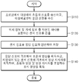
도 2는 도 1의 초음파 진단 장치의 동작 방법의 일 예를 나타내는 순서도이다.
도 3은 도 1의 출력부에 출력되는 표시 영상의 일 예를 나타내는 도면이다.
도 4는 표시 영상에 포함되는 영상 지시자의 일 예를 나타내는 도면이다.
도 5는 N개의 프레임 데이터 신호와 M개의 센서 서브신호 사이의 대응관계의 일 예를 나타낸다.
도 6은 도 1의 영상 처리부에서 표시 영상을 형성하는 방법의 일 예를 나타내는 도면이다.
도 7은 도 1의 저장부의 일 예를 나타내는 도면이다.
도 8은 도 1의 저장부의 다른 예를 나타내는 도면이다.
도 9는 도 1의 영상 처리부의 일 예를 나타내는 도면이다. 1 is a view showing an ultrasound diagnostic apparatus according to an embodiment of the present invention.
2 is a flowchart illustrating an example of an operating method of the ultrasound diagnosis apparatus of FIG. 1.
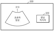
3 is a diagram illustrating an example of a display image output to an output unit of FIG. 1.
4 is a diagram illustrating an example of an image indicator included in a display image.
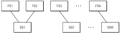
5 shows an example of a correspondence relationship between N frame data signals and M sensor sub-signals.
6 is a diagram illustrating an example of a method of forming a display image in the image processor of FIG. 1.
7 is a diagram illustrating an example of a storage unit of FIG. 1.
8 is a diagram illustrating another example of the storage unit of FIG. 1.
9 is a diagram illustrating an example of the image processor of FIG. 1.
이하에서는 도면을 참고하여 본 발명의 실시예들을 상세히 설명한다. Hereinafter, with reference to the drawings will be described embodiments of the present invention;
도 1은 본 발명의 실시예에 따른 초음파 진단 장치를 나타내는 도면이고, 도 2는 도 1의 초음파 진단 장치의 동작 방법의 일 예를 나타내는 순서도이다. 1 is a diagram illustrating an ultrasound diagnostic apparatus according to an exemplary embodiment of the present invention, and FIG. 2 is a flowchart illustrating an example of an operating method of the ultrasound diagnostic apparatus of FIG. 1.
도 1 및 도 2를 참고하면, 초음파 진단 장치(100)는 프로브(110), 검출부(120), 저장부(130), 영상 처리부(140)를 포함한다. 초음파 진단 장치(100)는 출력부(150) 및 입력부(160)를 더 포함할 수 있다. 1 and 2, the
프로브(110)는 대상체(object, 200)에 초음파 신호를 송신하고, 응답 신호를 수신한다(S110). 프로브(110)는 초음파 신호 송신 및 응답 신호 수신을 통해 대상체(200)를 스캔할 수 있다. 응답 신호는 대상체(200)를 투과한 신호이거나, 대상체(200)로부터 반사된 신호일 수 있다. The
대상체(200)는 인체를 포함하는 동물체이거나, 동물체의 일부일 수 있다. 예를 들어, 대상체(200)는 태아, 또는 동물체의 기관(organ)일 수 있다. The
검출부(120)는 프로브(110)의 3차원 위치를 나타내는 위치 정보 및 프로브(110)가 대상체에 대한 방향성을 나타내는 자세(orientation) 정보 중 적어도 하나를 포함하는 센서 신호를 획득한다(S120). 위치 정보는 3차원 좌표값 x, y, z이며, 자세 정보는 3차원 각도일 수 있다. 위치 정보에서 원점은 프로브(110)의 초기 위치 또는 대상체(200)일 수 있고, 자세 정보에서 원점은 대상체(200)일 수 있다. The
저장부(130)는 검출부(120)에서 획득되는 센서 신호를 응답 신호와 연관하여 저장한다(S130). The
영상 처리부(140)는 수신된 응답 신호에 기초해서 초음파 영상을 형성하고, 저장부(130)에 저장되어 있는 센서 신호에 기초해서 영상 지시자를 형성하며, 초음파 영상 및 초음파 영상에 대응하는 영상 지시자를 포함하는 표시 영상을 형성한다(S140).The
출력부(150)는 표시 영상을 출력할 수 있다. 출력부(150)는 표시 장치, 프린터 등일 수 있다. The
저장부(130)는 응답 신호에 기초하여 획득되는 데이터 신호를 더 저장할 수 있다. 데이터 신호는 영상 처리부(140)에서 처리될 수 있다. 영상 처리부(140)는 저장부(130)에 저장되어 있는 데이터 신호를 이용하여 초음파 영상을 형성하고, 저장부(130)에 저장되어 있는 센서 신호를 이용하여 영상 지시자를 형성할 수 있다. The
입력부(160)는 사용자로부터 사용자 요청을 입력받고, 사용자 요청을 영상 처리부(140)에 전달할 수 있다. 사용자 요청은 저장부(130)에 저장되어 데이터 신호의 출력을 지시하는 출력 요청을 포함할 수 있다. 입력부(160)로부터 출력 요청을 전달받는 경우, 영상 처리부(140)는 저장부(130)에 저장되어 있는 데이터 신호 및 센서 신호를 기반으로 표시 영상을 형성할 수 있다. The
도 3은 도 1의 출력부에 출력되는 표시 영상의 일 예를 나타내는 도면이다. 3 is a diagram illustrating an example of a display image output to an output unit of FIG. 1.
도 1 및 도 3을 참고하면, 출력부(150)에 출력되는 표시 영상(300)은 초음파 영상(310) 및 영상 지시자(320)를 포함한다. 1 and 3, the
도 3에서 표시 영상(300)은 초음파 영상(310)과 영상 지시자(320)가 분리되어 있으나, 도 3은 표시 영상(300)의 예시에 불과하다. 도 3과 달리, 영상 지시자(320)는 초음파 영상(310) 위에 중첩되어 표시될 수도 있다. In FIG. 3, the
도 4는 표시 영상에 포함되는 영상 지시자의 일 예를 나타내는 도면이다. 4 is a diagram illustrating an example of an image indicator included in a display image.
도 3 및 도 4를 참고하면, 영상 지시자(320)는 대상체(200)에 대한 위치 정보 또는 자세 정보를 이미지 및 텍스트 중 하나 이상을 이용하여 표시하는 마커일 수 있다. 영상 지시자(320)는 대상체(200)의 해부학적 축[Cr(Cranial)-Ca(Caudal), A(Anterior)-P(Posterior) 및 R(Right)-L(Left)]으로 구성된 좌표계 및 위치 정보 또는 자세 정보를 표시하는 화살표(321)를 포함할 수 있다. 좌표계의 원점(O)에는 대상체(200)의 중심이 위치할 수 있고, 화살표(321)의 끝(PR)에는 프로브(110)가 위치할 수 있다. 또한, 영상 지시자(320)는 대상체(200)의 해부학적 축(Cr-Ca, A-P 및 R-L)과 프로브(110)가 이루는 각도를 표시하는 텍스트(a, b)를 더 포함할 수 있다. 3 and 4, the
다만 도 4는 영상 지시자(320)의 일 예일 뿐, 영상 지시자(320)의 구현 예를 제한하는 것은 아니다. 영상 지시자(320)는 다양한 방법으로 대상체(200)에 대한 프로브(110)의 위치 정보 또는 자세 정보를 표시할 수 있다. 4 is only an example of the
다시 도 1을 참고하면, 검출부(120)는 프로브(110)가 대상체(200)를 스캔하는 스캔 구간 동안 프로브(110)의 위치 정보 또는 자세 정보를 검출할 수 있다. 스캔 구간 동안 프로브(110)의 3차원 위치 또는 자세는 고정될 수도 있고, 움직일 수도 있다. Referring back to FIG. 1, the
따라서 검출부(120)는 하나 이상의 연속적인 센서 신호를 검출할 수도 있다. 이때, 하나 이상의 센서 신호는 각각 위치 정보 및 자세 정보 중 적어도 하나를 포함한다. Accordingly, the
저장부(130)는 하나 이상의 센서 신호 및 하나 이상의 센서 신호 각각에 대응되는 하나 이상의 데이터 신호를 저장할 수 있다. 하나 이상의 데이터 신호는 상기 응답 신호에 기초하여 획득될 수 있다. The
영상 처리부(140)는 저장부(130)에 저장되어 있는 하나 이상의 센서 신호 및 하나 이상의 데이터 신호를 이용하여 하나 이상의 표시 영상을 획득할 수 있다. 표시 영상의 복수인 경우, 표시 영상은 동영상일 수 있다. 하나 이상의 표시 영상 각각은, 하나 이상의 센서 신호 중 대응되는 센서 신호에 기초해서 형성되는 영상 지시자 및 하나 이상의 데이터 신호 중 대응되는 데이터 신호에 기초해서 형성되는 초음파 영상을 포함할 수 있다. The
또는, 검출부(120)는 스캔 구간 동안 M개의 위치 정보 또는 자세 정보를 검출할 수 있다. 여기서, M은 자연수이다. 이 경우, 센서 신호는 M개의 위치 정보 또는 자세 정보에 대한 M개의 센서 서브신호를 포함할 수 있다. Alternatively, the
스캔 구간 동안 프로브(110)에서 획득되는 응답신호를 기반으로 N개의 프레임에 대한 데이터 신호가 획득될 수 있다. 여기서, N은 자연수이다. 이 경우, 데이터 신호는 N개의 프레임에 대한 N개의 프레임 데이터 신호를 포함할 수 있다. 제n 프레임 데이터 신호(n=1, 2, ..., N)는 제n 프레임에 대한 제n 프레임 초음파 영상을 출력하기 위한 신호이다. 예를 들어, 제n 프레임 데이터 신호는 복수의 화소값을 포함할 수 있다. Data signals for N frames may be obtained based on the response signal acquired by the
도 5는 N개의 프레임 데이터 신호와 M개의 센서 서브신호 사이의 대응관계의 일 예를 나타낸다. 5 shows an example of a correspondence relationship between N frame data signals and M sensor sub-signals.
도 5를 참고하면, N개의 프레임 데이터 신호(FS1, FS2, ..., FSN) 각각은 M개의 센서 서브신호(SS1, SS2, ..., SSM) 중 하나의 매칭 센서 서브신호에 대응될 수 있다. M개의 센서 서브신호(SS1, SS2, ..., SSM) 각각은 N개의 프레임 중 하나 이상의 매칭 프레임에 대응될 수 있다. Referring to FIG. 5, each of the N frame data signals FS1, FS2,..., And FSN may correspond to one matching sensor subsignal of M sensor subsignals SS1, SS2,..., SSM. Can be. Each of the M sensor sub-signals SS1, SS2,..., SSM may correspond to one or more matching frames of N frames.
N개의 프레임 데이터 신호(FS1, FS2, ..., FSN)와 M개의 센서 서브신호(SS1, SS2, ..., SSM)는 스캔 구간 동안 서로 독립적으로 획득될 수 있다. 이 경우, N개의 프레임 데이터 신호(FS1, FS2, ..., FSN)가 획득되는 시간과 M개의 센서 서브신호(SS1, SS2, ..., SSM)가 획득되는 시간을 기반으로 대응관계가 결정될 수 있다. The N frame data signals FS1, FS2,..., And FSN and the M sensor sub-signals SS1, SS2,..., SSM may be obtained independently of each other during the scan period. In this case, the correspondence relationship is based on the time when the N frame data signals FS1, FS2, ..., FSN are acquired and the time when the M sensor sub-signals SS1, SS2, ..., SSM are acquired. Can be determined.
도 5에서 제1 프레임 데이터 신호(FS1)와 제2 프레임 데이터 신호(FS2)는 제1 센서 서브신호(SS1)에 대응된다. 즉, 제1 프레임의 매칭 센서 서브신호와 제2 프레임의 매칭 센서 서브신호는 제1 센서 서브신호(SS1)이고, 제1 센서 서브신호(SS1)의 매칭 프레임은 제1 프레임 및 제2 프레임이다. In FIG. 5, the first frame data signal FS1 and the second frame data signal FS2 correspond to the first sensor sub-signal SS1. That is, the matching sensor subsignal of the first frame and the matching sensor subsignal of the second frame are the first sensor subsignal SS1, and the matching frames of the first sensor subsignal SS1 are the first frame and the second frame. .
도 5에서는 N개의 프레임 데이터 신호(FS1, FS2, ..., FSN)와 M개의 센서 서브신호(SS1, SS2, ..., SSM)가 다대일로 대응된다. 다만, 도 5는 대응관계의 일 예일 뿐이다. N개의 프레임 데이터 신호(FS1, FS2, ..., FSN)와 M개의 센서 서브신호(SS1, SS2, ..., SSM)는 일대일, 다대일, 일대다 등 다양한 대응관계가 가능하다. In FIG. 5, N frame data signals FS1, FS2, ..., FSN and M sensor sub-signals SS1, SS2, ..., SSM correspond on a many-to-one basis. 5 is only an example of a corresponding relationship. The N frame data signals FS1, FS2, ..., FSN and the M sensor sub-signals SS1, SS2, ..., SSM can have various correspondences such as one-to-one, many-to-one and one-to-many.
도 6은 도 1의 영상 처리부에서 표시 영상을 형성하는 방법의 일 예를 나타내는 도면이다. 6 is a diagram illustrating an example of a method of forming a display image in the image processor of FIG. 1.
도 1 및 도 6을 참고하면, 영상 처리부(140)에서 형성되는 표시 영상(300A)은 N개의 프레임에 대한 N개의 프레임 표시 영상(300-1, 300-2, ..., 300-N)을 포함할 수 있다. 제n 프레임에 대한 제n 프레임 표시 영상(n=1, 2, ..., N)은 제n 프레임 초음파 영상(310-n) 및 제n 프레임 영상 지시자(320-n)를 포함할 수 있다. 1 and 6, the
저장부(130)에는 N개의 프레임 데이터 신호(FS1, FS2, ..., FSN) 및 M개의 센서 서브신호(SS1, SS2, ..., SSM)가 저장되어 있다. 도 6에서 N개의 프레임 데이터 신호(FS1, FS2, ..., FSN) 및 M개의 센서 서브신호(SS1, SS2, ..., SSM)의 대응관계는 도 5의 대응관계와 동일하다고 가정한다. The
영상 처리부(140)는 저장부(130)에 저장되어 있는 제n 프레임 데이터 신호(FSn)를 기반으로 제n 프레임 초음파 영상(310-n)을 형성할 수 있다. 영상 처리부(140)는 저장부(130)에 저장되어 있는 M개의 센서 서브신호(SS1, SS2, ..., SSM) 중 제n 프레임의 매칭 센서 서브신호를 기반으로 제n 프레임 영상 지시자(320-n)를 형성할 수 있다. 예를 들어, 제3 프레임 영상 지시자(320-3)는 제3 프레임의 매칭 센서 서브신호인 제2 센서 서브신호(SS2)를 기반으로 형성될 수 있다. The
영상 처리부(140)가 M개의 센서 서브신호(SS1, SS2, ..., SSM) 중 제n 프레임의 매칭 센서 서브신호를 식별하기 위해, 저장부(130)는 N개의 프레임 데이터 신호(FS1, FS2, ..., FSN)와 M개의 센서 서브신호(SS1, SS2, ..., SSM)의 대응관계를 지시하는 관계 정보를 더 저장할 수 있다. In order for the
도 7은 도 1의 저장부의 일 예를 나타내는 도면이다. 7 is a diagram illustrating an example of a storage unit of FIG. 1.
도 1 및 도 7을 참고하면, 저장부(130)는 데이터 신호(FS)에 포함되는 N개의 프레임 데이터 신호(FS1, FS2, ..., FSN)와 센서 신호(SS)에 포함되는 M개의 센서 서브신호(SS1, SS2, ..., SSM)를 저장할 수 있다. 1 and 7, the
M개의 센서 서브신호(SS1, SS2, ..., SSM)는 각각 센서 정보(LI1, LI2, ..., LIM) 및 프레임 정보(FI1, FI2, ..., FIM)를 포함할 수 있다. 센서 정보(LI1, LI2, ..., LIM)는 프로브(110)의 위치 정보 및 자세 정보 중 적어도 하나를 지시한다. 각 프레임 정보(FI1, FI2, ..., FIM)는 대응되는 센서 서브신호의 매칭 프레임을 지시한다. The M sensor sub-signals SS1, SS2, ..., SSM may include sensor information LI1, LI2, ..., LIM and frame information FI1, FI2, ..., FIM, respectively. . The sensor information LI1, LI2,..., LIM indicate at least one of position information and attitude information of the
도 7에서 N개의 프레임 데이터 신호(FS1, FS2, ..., FSN) 및 M개의 센서 서브신호(SS1, SS2, ..., SSM)의 대응관계가 도 5의 대응관계와 동일하다고 가정할 경우, 제1 센서 서브신호(SS1)에 포함되는 프레임 정보(FI1)는 제1 프레임 및 제2 프레임을 지시할 수 있다. In FIG. 7, it is assumed that the correspondence between the N frame data signals FS1, FS2,..., And FSN and the M sensor sub-signals SS1, SS2,. In this case, the frame information FI1 included in the first sensor sub-signal SS1 may indicate the first frame and the second frame.
도 8은 도 1의 저장부의 다른 예를 나타내는 도면이다. 8 is a diagram illustrating another example of the storage unit of FIG. 1.
도 1 및 도 8을 참고하면, 저장부(130)는 N개의 프레임 데이터 신호(FS1, FS2, ..., FSN)와 M개의 센서 서브신호(SS1, SS2, ..., SSM) 및 관계 정보(FS-SS)를 지시하는 정보 테이블(ITB)을 저장할 수 있다. 1 and 8, the
다만, 도 7 및 도 8은 저장부의 일 예일 뿐, 저장부(130)에 N개의 프레임 데이터 신호(FS1, FS2, ..., FSN)와 M개의 센서 서브신호(SS1, SS2, ..., SSM) 및 관계 정보(FS-SS)의 저장 방법을 제한하는 것은 아니다. 7 and 8 are merely examples of the storage unit, and the N frame data signals FS1, FS2, ..., FSN and the M sensor sub-signals SS1, SS2, ... are stored in the
도 9는 도 1의 영상 처리부(140)의 일 예를 나타내는 도면이다. 9 is a diagram illustrating an example of the
도 1 및 도 9를 참고하면, 영상 처리부(140)는 제1 형성부(141), 제2 형성부(142) 및 제3 형성부(143)를 포함할 수 있다. 제1 형성부(141)는 프로브(110)가 수신한 응답 신호에 기초해서 초음파 영상을 획득할 수 있다. 제2 형성부(142)는 저장부(130)에 저장되어 있는 센서 신호에 기초해서 영상 지시자를 획득할 수 있다. 제3 형성부(143)는 초음파 영상 및 초음파 영상에 대응하는 영상 지시자를 포함하는 표시 영상을 획득할 수 있다. 1 and 9, the
도 9는 영상 처리부(140)의 하나의 구현예이다. 다른 예로, 제1 형성부(141), 제2 형성부(142) 및 제3 형성부(143)는 각각 독립된 프로세서일 수 있다. 또 다른 예로, 제1 형성부(141), 제2 형성부(142) 및 제3 형성부(143)는 하나의 프로세서로 구현될 수도 있다. 9 is an embodiment of the
이와 같이, 본 발명의 실시예에 따르면, 사용자가 대상체를 스캔하는 상황을 직관적으로 인식할 수 있는 초음파 진단 장치 및 그 동작 방법을 제공할 수 있다.As described above, according to an exemplary embodiment of the present invention, an ultrasound diagnosis apparatus and an operation method thereof may be provided to intuitively recognize a situation in which a user scans an object.
초음파 진단 장치는 프로브가 대상체를 스캔하는 동안 대상체에 대한 프로브의 3차원 위치 또는 자세를 지시하는 센서 정보를 포함하는 센서 신호를 자동으로 저장부에 저장할 수 있다. 따라서 사용자가 초음파 영상에 영상 지시자를 표시하기 위해 대상체를 프로브로 스캔하면서 초음파 진단 장치를 조작할 필요가 없다. 따라서 조작성, 효율성, 생산성 등이 개선될 수 있다. The ultrasound diagnosis apparatus may automatically store a sensor signal including sensor information indicating a 3D position or posture of the probe with respect to the object while the probe scans the object. Therefore, the user does not need to manipulate the ultrasound diagnostic apparatus while scanning the object with a probe to display an image indicator on the ultrasound image. Therefore, operability, efficiency, productivity, and the like can be improved.
저장부에 저장되어 있는 데이터 신호를 기반으로 초음파 영상을 출력하는 경우, 저장부에 저장되어 있는 센서 신호를 기반으로 영상 지시자가 초음파 영상과 함께 출력된다. 따라서 사용자는 영상 지시자를 통해 대상체의 스캔 상태를 직관적으로 인식할 수 있다. When the ultrasound image is output based on the data signal stored in the storage unit, the image indicator is output together with the ultrasound image based on the sensor signal stored in the storage unit. Therefore, the user may intuitively recognize the scanning state of the object through the image indicator.
또한, 대상체를 스캔한 사람과 초음파 영상을 진단하는 사람이 다른 경우에도, 스캔한 사람과 진단한 사람 사이의 의사소통이 쉽고 명확해지는 편의를 제공할 수 있다. In addition, even when the person who scans the object and the person who diagnoses the ultrasound image are different from each other, communication between the scanned person and the diagnosed person may be easily and clearly provided.
한편, 상술한 방법은 컴퓨터에서 실행될 수 있는 프로그램으로 작성 가능하고, 컴퓨터로 읽을 수 있는 기록매체를 이용하여 상기 프로그램을 동작시키는 범용 디지털 컴퓨터에서 구현될 수 있다. 또한, 상술한 방법에서 사용된 데이터의 구조는 컴퓨터로 읽을 수 있는 기록매체에 여러 수단을 통하여 기록될 수 있다. 상기 컴퓨터로 읽을 수 있는 기록매체는 마그네틱 저장매체(예를 들면, 롬, 램, USB, 플로피 디스크, 하드 디스크 등), 광학적 판독 매체(예를 들면, 시디롬, 디브이디 등), PC 인터페이스(PC Interface)(예를 들면, PCI, PCI-express, Wifi 등)와 같은 저장매체를 포함한다.Meanwhile, the above-described method can be implemented in a general-purpose digital computer that can be created as a program that can be executed by a computer and operates the program using a computer-readable recording medium. In addition, the structure of the data used in the above-described method can be recorded on a computer-readable recording medium through various means. The computer readable recording medium may be a magnetic storage medium such as a ROM, a RAM, a USB, a floppy disk or a hard disk, an optical reading medium such as a CD-ROM or a DVD, ) (E.g., PCI, PCI-express, Wifi, etc.).
본 실시예와 관련된 기술 분야에서 통상의 지식을 가진 자는 상기된 기재의 본질적인 특성에서 벗어나지 않는 범위에서 변형된 형태로 구현될 수 있음을 이해할 수 있을 것이다. 그러므로 개시된 방법들은 한정적인 관점이 아니라 설명적인 관점에서 고려되어야 한다. 본 발명의 범위는 전술한 설명이 아니라 특허청구범위에 나타나 있으며, 그와 동등한 범위 내에 있는 모든 차이점은 본 발명에 포함된 것으로 해석되어야 할 것이다. It will be understood by those skilled in the art that various changes in form and details may be made therein without departing from the spirit and scope of the invention as defined by the appended claims. Therefore, the disclosed methods should be considered from an illustrative point of view, not from a restrictive point of view. The scope of the present invention is defined by the appended claims rather than by the foregoing description, and all differences within the scope of equivalents thereof should be construed as being included in the present invention.
Claims (25)
상기 프로브의 3차원 위치를 나타내는 위치 정보 및 상기 프로브가 상기 대상체에 대한 방향성을 나타내는 자세(orientation) 정보 중 적어도 하나를 포함하는 센서 신호를 검출하는 검출부;
상기 센서 신호를 상기 응답 신호와 연관하여 저장하는 저장부; 및
상기 수신된 응답 신호에 기초해서 초음파 영상을 형성하고, 상기 저장부에 저장되어 있는 상기 센서 신호에 기초해서 영상 지시자를 형성하며, 상기 초음파 영상 및 상기 초음파 영상에 대응하는 상기 영상 지시자를 포함하는 표시 영상을 형성하는 영상 처리부를 포함하는 것을 특징으로 하는 초음파 진단 장치.A probe transmitting an ultrasound signal to an object and receiving a response signal from the object;
A detector for detecting a sensor signal including at least one of position information indicating a three-dimensional position of the probe and orientation information indicating the orientation of the probe with respect to the object;
A storage unit to store the sensor signal in association with the response signal; And
A display including an ultrasound image based on the received response signal, an image indicator based on the sensor signal stored in the storage, and including the ultrasound image and the image indicator corresponding to the ultrasound image Ultrasonic diagnostic apparatus comprising an image processing unit for forming an image.
상기 표시 영상을 출력하는 출력부를 더 포함하는 것을 특징으로 하는 초음파 진단 장치.The method of claim 1,
And an output unit for outputting the display image.
상기 저장부는 상기 응답 신호에 기초하여 획득되는 데이터 신호를 더 저장하고,
상기 영상 처리부는 상기 저장부에 저장되어 있는 상기 데이터 신호를 이용하여 상기 초음파 영상을 형성하고, 상기 저장부에 저장되어 있는 상기 센서 신호를 이용하여 상기 영상 지시자를 형성하는 것을 특징으로 하는 초음파 진단 장치. The method of claim 1,
The storage unit further stores a data signal obtained based on the response signal,
The image processor may form the ultrasound image using the data signal stored in the storage unit, and form the image indicator using the sensor signal stored in the storage unit. .
상기 데이터 신호는 N개의 프레임에 대한 N개의 프레임 데이터 신호를 포함하고, 상기 센서 신호는 M개의 센서 서브신호를 포함하고,
상기 N개의 프레임 데이터 신호 각각은 상기 M개의 센서 서브신호 중 하나의 센서 서브신호에 대응되고, N과 M은 각각 자연수인 것을 특징으로 하는 초음파 진단 장치. 5. The method of claim 4,
The data signal includes N frame data signals for N frames, the sensor signal includes M sensor sub-signals,
Each of the N frame data signals corresponds to one sensor sub-signal of the M sensor sub-signals, and N and M are natural numbers, respectively.
상기 표시 영상은 상기 N개의 프레임에 대한 N개의 프레임 표시 영상을 포함하고, 상기 N개의 프레임 표시 영상 중 제n 프레임에 대한 제n 프레임 표시 영상(n=1, 2, ..., N)은 제n 프레임 초음파 영상 및 상기 제n 프레임 영상 지시자를 포함하는 것을 특징으로 하는 초음파 진단 장치. The method of claim 5,
The display image includes N frame display images for the N frames, and an nth frame display image (n = 1, 2, ..., N) for an nth frame among the N frame display images And an nth frame ultrasound image and the nth frame image indicator.
상기 영상 처리부는 상기 저장부에 저장되어 있는 제n 프레임 데이터 신호에 기초하여 상기 제n 프레임 초음파 영상을 형성하고, 상기 저장부에 저장되어 있는 상기 M개의 센서 서브신호 중 상기 제n 프레임 데이터 신호에 대응하는 센서 서브신호에 기초하여 상기 제n 프레임 영상 지시자를 형성하는 것을 특징으로 하는 초음파 진단 장치. The method according to claim 6,
The image processing unit forms the n-th frame ultrasound image based on the n-th frame data signal stored in the storage unit, and the n-th frame data signal is stored among the M sensor sub-signals stored in the storage unit. And an n-th frame image indicator based on a corresponding sensor sub-signal.
상기 저장부는 상기 N개의 프레임 데이터 신호와 상기 M개의 센서 서브신호의 대응관계를 지시하는 관계 정보를 더 저장하는 것을 특징으로 하는 초음파 진단 장치. The method of claim 7, wherein
And the storage unit further stores relationship information indicating a corresponding relationship between the N frame data signals and the M sensor sub-signals.
상기 관계 정보는 상기 M개의 센서 서브신호 각각에 포함되는 프레임 정보이거나,
상기 저장부는 상기 N개의 프레임 데이터 신호, 상기 M개의 센서 서브신호 및 상기 관계 정보를 지시하는 정보 테이블을 저장하는 것을 특징으로 하는 초음파 진단 장치. 9. The method of claim 8,
The relationship information is frame information included in each of the M sensor sub-signals,
And the storage unit stores the N frame data signals, the M sensor sub-signals, and an information table indicating the relationship information.
상기 영상 지시자는 상기 대상체에 대한 상기 위치 정보 및 상기 자세 정보를 이미지 및 텍스트 중 적어도 하나를 이용하여 표시하는 마커인 것을 특징으로 하는 초음파 진단 장치. The method of claim 1,
The image indicator is an ultrasound diagnostic apparatus, characterized in that for displaying the position information and the posture information on the object using at least one of an image and text.
상기 영상 지시자는 초음파 영상 위에 있는 것을 특징으로 하는 초음파 진단 장치.The method of claim 1,
And the image indicator is on an ultrasound image.
상기 프로브의 3차원 위치를 나타내는 위치 정보 및 상기 프로브가 상기 대상체에 대한 방향성을 나타내는 자세(orientation) 정보 중 적어도 하나를 포함하는 센서 신호를 검출하는 단계;
상기 센서 신호를 상기 응답 신호와 연관하여 저장하는 단계; 및
상기 수신된 응답 신호에 기초해서 초음파 영상을 형성하고, 상기 저장되어 있는 상기 센서 신호에 기초해서 영상 지시자를 형성하며, 상기 초음파 영상 및 상기 영상 지시자를 포함하는 표시 영상을 형성하는 단계를 포함하는 것을 특징으로 하는 초음파 진단 장치의 동작 방법.Transmitting an ultrasound signal to an object from a probe and receiving a response signal from the object;
Detecting a sensor signal including at least one of position information indicating a three-dimensional position of the probe and orientation information indicating the orientation of the probe with respect to the object;
Storing the sensor signal in association with the response signal; And
Forming an ultrasound image based on the received response signal, forming an image indicator based on the stored sensor signal, and forming a display image including the ultrasound image and the image indicator. An operating method of the ultrasonic diagnostic apparatus.
상기 초음파 진단 장치의 진단 방법은 상기 응답 신호에 기초하여 획득되는 데이터 신호를 저장하는 단계를 더 포함하며,
상기 표시 영상을 형성하는 단계는 상기 저장되어 있는 상기 데이터 신호를 이용하여 초음파 영상을 형성하고, 상기 저장되어 있는 상기 센서 신호를 이용하여 영상 지시자를 형성하는 것을 특징으로 하는 초음파 진단 장치의 동작 방법. The method of claim 12,
The diagnostic method of the ultrasound diagnostic apparatus further comprises storing a data signal obtained based on the response signal,
The forming of the display image may include forming an ultrasound image by using the stored data signal, and forming an image indicator by using the stored sensor signal.
상기 데이터 신호는 N개의 프레임에 대한 N개의 프레임 데이터 신호를 포함하고, 상기 센서 신호는 M개의 센서 서브신호를 포함하고,
상기 N개의 프레임 데이터 신호 각각은 상기 M개의 센서 서브신호 중 하나의 센서 서브신호에 대응되고, N과 M은 각각 자연수인 것을 특징으로 하는 초음파 진단 장치의 동작 방법. 16. The method of claim 15,
The data signal includes N frame data signals for N frames, the sensor signal includes M sensor sub-signals,
Each of the N frame data signals corresponds to one sensor sub-signal of the M sensor sub-signals, and N and M are natural numbers, respectively.
상기 표시 영상은 상기 N개의 프레임에 대한 N개의 프레임 표시 영상을 포함하고, 상기 N개의 프레임 표시 영상 중 제n 프레임에 대한 제n 프레임 표시 영상(n=1, 2, ..., N)은 제n 프레임 초음파 영상 및 상기 제n 프레임 영상 지시자를 포함하는 것을 특징으로 하는 초음파 진단 장치의 진단 방법. 17. The method of claim 16,
The display image includes N frame display images for the N frames, and an nth frame display image (n = 1, 2, ..., N) for an nth frame among the N frame display images And a n-th frame ultrasound image and the n-th frame image indicator.
상기 초음파 영상을 형성하는 단계는 상기 저장되어 있는 제n 프레임 데이터 신호에 기초하여 상기 제n 프레임 초음파 영상을 형성하는 단계를 포함하고,
상기 영상 지시자를 형성하는 단계는 상기 저장되어 있는 상기 M개의 센서 서브신호 중 상기 제n 프레임 데이터 신호에 대응하는 센서 서브신호에 기초하여 상기 제n 프레임 영상 지시자를 형성하는 단계를 포함하는 것을 특징으로 하는 초음파 진단 장치의 동작 방법. 18. The method of claim 17,
The forming of the ultrasound image may include forming the n-th frame ultrasound image based on the stored n-th frame data signal.
The forming of the image indicator may include forming the n-th frame image indicator based on a sensor sub-signal corresponding to the n-th frame data signal among the stored M sensor sub-signals. Method of operation of the ultrasonic diagnostic apparatus.
상기 영상 지시자는 초음파 영상 위에 있는 것을 특징으로 하는 초음파 진단 장치의 동작 방법.The method of claim 12,
And the image indicator is on an ultrasound image.
상기 프로브의 3차원 위치를 나타내는 위치정보 및 상기 프로브가 상기 대상체에 대한 방향성을 나타내는 자세(orientation) 정보 중 적어도 하나를 검출하는 검출부;
상기 위치 정보 및 상기 자세 정보 중 적어도 하나를 상기 수신된 응답 신호와 연관하여 저장하는 저장부를 포함하는 것을 특징으로 하는 초음파 진단 장치.A probe transmitting an ultrasound signal to an object and receiving a response signal from the object;
A detector configured to detect at least one of position information indicating a three-dimensional position of the probe and orientation information indicating the orientation of the probe with respect to the object;
And a storage unit which stores at least one of the position information and the posture information in association with the received response signal.
상기 프로브의 3차원 위치를 나타내는 위치 정보 및 상기 프로브가 상기 대상체에 대한 방향성을 나타내는 자세(orientation) 정보 중 적어도 하나를 검출하는 단계와;
상기 위치 정보 및 상기 자세 정보 중 적어도 하나를 상기 수신된 응답 신호와 연관하여 저장하는 단계를 포함하는 것을 특징으로 하는 초음파 진단 장치의 동작 방법.Transmitting an ultrasound signal to an object from a probe and receiving a response signal from the object;
Detecting at least one of position information indicating a three-dimensional position of the probe and orientation information indicating orientation of the object with the probe;
And storing at least one of the location information and the posture information in association with the received response signal.
하나 이상의 연속적인 센서 신호를 검출하되, 상기 하나 이상의 센서 신호는 각각 상기 프로브의 3차원 위치를 나타내는 위치 정보 및 상기 프로브가 상기 대상체에 대한 방향성을 나타내는 자세(orientation) 정보 중 적어도 하나를 포함하는, 검출부;
상기 하나 이상의 센서 신호 및 상기 하나 이상의 센서 신호 각각에 대응되는 하나 이상의 데이터 신호를 저장하되, 상기 하나 이상의 데이터 신호는 상기 응답 신호에 기초하여 획득되는, 저장부; 및
상기 저장부에 저장되어 있는 상기 하나 이상의 센서 신호 및 상기 하나 이상의 데이터 신호를 이용하여 하나 이상의 표시 영상을 형성하되,
상기 하나 이상의 표시 영상 각각은, 상기 하나 이상의 센서 신호 중 대응되는 센서 신호에 기초해서 형성되는 영상 지시자 및 상기 하나 이상의 데이터 신호 중 대응되는 데이터 신호에 기초해서 형성되는 초음파 영상을 처리하는, 영상 처리부를 포함하는 것을 특징으로 하는 초음파 진단 장치.A probe transmitting an ultrasound signal to an object and receiving a response signal from the object;
Detecting one or more continuous sensor signals, wherein the one or more sensor signals each include at least one of position information indicating a three-dimensional position of the probe and orientation information indicating the orientation of the probe to the object; Detection unit;
A storage unit storing one or more sensor signals and one or more data signals corresponding to each of the one or more sensor signals, wherein the one or more data signals are obtained based on the response signal; And
One or more display images are formed using the one or more sensor signals and the one or more data signals stored in the storage unit.
Each of the one or more display images may include an image processor configured to process an image indicator formed based on a corresponding sensor signal among the one or more sensor signals and an ultrasound image formed based on a corresponding data signal among the one or more data signals. Ultrasonic diagnostic apparatus comprising a.
상기 프로브의 3차원 위치를 나타내는 위치 정보 및 상기 프로브가 상기 대상체에 대한 방향성을 나타내는 자세(orientation) 정보 중 적어도 하나를 포함하는 센서 신호를 검출하는 검출부;
상기 센서 신호를 상기 응답 신호와 연관하여 저장하는 저장부;
상기 수신된 응답 신호에 기초해서 초음파 영상을 형성하는 제1 형성부;
상기 저장부에 저장되어 있는 상기 센서 신호에 기초해서 영상 지시자를 형성하는 제2 형성부; 및
상기 초음파 영상 및 상기 초음파 영상에 대응하는 상기 영상 지시자를 포함하는 표시 영상을 형성하는 제3 형성부를 포함하는 것을 특징으로 하는 초음파 진단 장치.A probe transmitting an ultrasound signal to an object and receiving a response signal from the object;
A detector for detecting a sensor signal including at least one of position information indicating a three-dimensional position of the probe and orientation information indicating the orientation of the probe with respect to the object;
A storage unit to store the sensor signal in association with the response signal;
A first forming unit which forms an ultrasound image based on the received response signal;
A second forming unit to form an image indicator based on the sensor signal stored in the storage unit; And
And a third forming unit configured to form a display image including the ultrasound image and the image indicator corresponding to the ultrasound image.
상기 제1 형성부, 제2 형성부 및 제3 형성부는 영상 처리부에 포함되는 것을 특징으로 하는 초음파 진단 장치.25. The method of claim 24,
And the first forming part, the second forming part, and the third forming part are included in an image processor.
Applications Claiming Priority (2)
| Application Number | Priority Date | Filing Date | Title |
|---|---|---|---|
| KR20120031215 | 2012-03-27 | ||
| KR1020120031215 | 2012-03-27 |
Publications (1)
| Publication Number | Publication Date |
|---|---|
| KR20130110033A true KR20130110033A (en) | 2013-10-08 |
Family
ID=48143052
Family Applications (1)
| Application Number | Title | Priority Date | Filing Date |
|---|---|---|---|
| KR1020130028233A KR20130110033A (en) | 2012-03-27 | 2013-03-15 | Ulrtasound diagnosis apparatus and operating method thereof |
Country Status (4)
| Country | Link |
|---|---|
| US (1) | US20130261448A1 (en) |
| EP (1) | EP2644100A1 (en) |
| JP (1) | JP2013202412A (en) |
| KR (1) | KR20130110033A (en) |
Families Citing this family (7)
| Publication number | Priority date | Publication date | Assignee | Title |
|---|---|---|---|---|
| US10667790B2 (en) | 2012-03-26 | 2020-06-02 | Teratech Corporation | Tablet ultrasound system |
| US9877699B2 (en) | 2012-03-26 | 2018-01-30 | Teratech Corporation | Tablet ultrasound system |
| KR20150082945A (en) * | 2014-01-08 | 2015-07-16 | 삼성메디슨 주식회사 | Ultrasonic diagnostic apparatus and operating method for the same |
| CN105769243B (en) * | 2016-03-17 | 2018-10-09 | 辽宁石油化工大学 | A kind of diagnostic ultrasound equipment |
| KR101818726B1 (en) | 2016-11-14 | 2018-01-18 | 테라셈 주식회사 | Endoscope apparatus and control method thereof |
| KR101859717B1 (en) * | 2016-12-22 | 2018-06-01 | 테라셈 주식회사 | Endoscope apparatus and control method thereof |
| CN112155596B (en) * | 2020-10-10 | 2023-04-07 | 达闼机器人股份有限公司 | Ultrasonic diagnostic apparatus, method of generating ultrasonic image, and storage medium |
Family Cites Families (4)
| Publication number | Priority date | Publication date | Assignee | Title |
|---|---|---|---|---|
| JP4167162B2 (en) * | 2003-10-14 | 2008-10-15 | アロカ株式会社 | Ultrasonic diagnostic equipment |
| JP4263579B2 (en) * | 2003-10-22 | 2009-05-13 | アロカ株式会社 | Ultrasonic diagnostic equipment |
| US9439624B2 (en) * | 2007-10-19 | 2016-09-13 | Metritrack, Inc. | Three dimensional mapping display system for diagnostic ultrasound machines and method |
| KR101182880B1 (en) * | 2009-01-28 | 2012-09-13 | 삼성메디슨 주식회사 | Ultrasound system and method for providing image indicator |
-
2013
- 2013-03-15 KR KR1020130028233A patent/KR20130110033A/en not_active Application Discontinuation
- 2013-03-22 EP EP13160621.2A patent/EP2644100A1/en not_active Withdrawn
- 2013-03-26 JP JP2013064904A patent/JP2013202412A/en active Pending
- 2013-03-27 US US13/851,697 patent/US20130261448A1/en not_active Abandoned
Also Published As
| Publication number | Publication date |
|---|---|
| US20130261448A1 (en) | 2013-10-03 |
| EP2644100A1 (en) | 2013-10-02 |
| JP2013202412A (en) | 2013-10-07 |
Similar Documents
| Publication | Publication Date | Title |
|---|---|---|
| KR20130110033A (en) | Ulrtasound diagnosis apparatus and operating method thereof | |
| JP5685133B2 (en) | Image processing apparatus, image processing apparatus control method, and program | |
| US20110066031A1 (en) | Ultrasound system and method of performing measurement on three-dimensional ultrasound image | |
| US8900147B2 (en) | Performing image process and size measurement upon a three-dimensional ultrasound image in an ultrasound system | |
| JP6097452B2 (en) | Ultrasonic imaging system and ultrasonic imaging method | |
| JP6196951B2 (en) | Ultrasonic diagnostic image generation apparatus and method | |
| EP3192053A1 (en) | Quality metric for multi-beat echocardiographic acquisitions for immediate user feedback | |
| RU2015113443A (en) | DEVICE FOR ULTRASONIC VISUALIZATION CONTROLLED BY MOBILE DISPLAY DEVICE AND ULTRASONIC VISUALIZATION SYSTEM | |
| JP2016540583A (en) | Ultrasonic imaging assembly and method for displaying an ultrasound image | |
| JP2007097902A (en) | Ultrasonic inspection system | |
| US20110251488A1 (en) | Method and system for displaying system parameter information | |
| RU2017111807A (en) | DEVICE OF MEDICAL VISUALIZATION | |
| JP2006246974A (en) | Ultrasonic diagnostic equipment with reference image display function | |
| KR101517752B1 (en) | Diagnosis image apparatus and operating method thereof | |
| US20210312835A1 (en) | Systems and methods for providing an interactive demonstration of an ultrasound user interface | |
| US20140236012A1 (en) | Ultrasound diagnosis apparatus | |
| JP2009101073A (en) | Ultrasonic imaging apparatus | |
| KR100875620B1 (en) | Ultrasound Imaging Systems and Methods | |
| US20140276045A1 (en) | Method and apparatus for processing ultrasound data using scan line information | |
| JP4868845B2 (en) | Ultrasonic diagnostic apparatus and ultrasonic measurement method | |
| JP5465893B2 (en) | Ultrasonic diagnostic apparatus and control program therefor | |
| JP2018102891A (en) | Ultrasonic image display apparatus and control program therefor | |
| EP2807977B1 (en) | Ultrasound diagnosis method and aparatus using three-dimensional volume data | |
| KR20200099910A (en) | Apparatus and method for displaying ultrasound image and computer program product | |
| JP5648990B2 (en) | Ultrasonic diagnostic equipment |
Legal Events
| Date | Code | Title | Description |
|---|---|---|---|
| A201 | Request for examination | ||
| E601 | Decision to refuse application |