KR20130101609A - Apparatus supporting a pair of front wheel of bicycles and motorcycles - Google Patents
Apparatus supporting a pair of front wheel of bicycles and motorcycles Download PDFInfo
- Publication number
- KR20130101609A KR20130101609A KR1020120012783A KR20120012783A KR20130101609A KR 20130101609 A KR20130101609 A KR 20130101609A KR 1020120012783 A KR1020120012783 A KR 1020120012783A KR 20120012783 A KR20120012783 A KR 20120012783A KR 20130101609 A KR20130101609 A KR 20130101609A
- Authority
- KR
- South Korea
- Prior art keywords
- shaft
- front wheel
- wheel support
- hub
- steering
- Prior art date
Links
Images


Classifications
-
- B—PERFORMING OPERATIONS; TRANSPORTING
- B62—LAND VEHICLES FOR TRAVELLING OTHERWISE THAN ON RAILS
- B62K—CYCLES; CYCLE FRAMES; CYCLE STEERING DEVICES; RIDER-OPERATED TERMINAL CONTROLS SPECIALLY ADAPTED FOR CYCLES; CYCLE AXLE SUSPENSIONS; CYCLE SIDE-CARS, FORECARS, OR THE LIKE
- B62K5/00—Cycles with handlebars, equipped with three or more main road wheels
- B62K5/08—Cycles with handlebars, equipped with three or more main road wheels with steering devices acting on two or more wheels
-
- B—PERFORMING OPERATIONS; TRANSPORTING
- B62—LAND VEHICLES FOR TRAVELLING OTHERWISE THAN ON RAILS
- B62K—CYCLES; CYCLE FRAMES; CYCLE STEERING DEVICES; RIDER-OPERATED TERMINAL CONTROLS SPECIALLY ADAPTED FOR CYCLES; CYCLE AXLE SUSPENSIONS; CYCLE SIDE-CARS, FORECARS, OR THE LIKE
- B62K15/00—Collapsible or foldable cycles
- B62K15/006—Collapsible or foldable cycles the frame being foldable
-
- B—PERFORMING OPERATIONS; TRANSPORTING
- B62—LAND VEHICLES FOR TRAVELLING OTHERWISE THAN ON RAILS
- B62K—CYCLES; CYCLE FRAMES; CYCLE STEERING DEVICES; RIDER-OPERATED TERMINAL CONTROLS SPECIALLY ADAPTED FOR CYCLES; CYCLE AXLE SUSPENSIONS; CYCLE SIDE-CARS, FORECARS, OR THE LIKE
- B62K25/00—Axle suspensions
- B62K25/04—Axle suspensions for mounting axles resiliently on cycle frame or fork
-
- B—PERFORMING OPERATIONS; TRANSPORTING
- B62—LAND VEHICLES FOR TRAVELLING OTHERWISE THAN ON RAILS
- B62K—CYCLES; CYCLE FRAMES; CYCLE STEERING DEVICES; RIDER-OPERATED TERMINAL CONTROLS SPECIALLY ADAPTED FOR CYCLES; CYCLE AXLE SUSPENSIONS; CYCLE SIDE-CARS, FORECARS, OR THE LIKE
- B62K5/00—Cycles with handlebars, equipped with three or more main road wheels
- B62K5/01—Motorcycles with four or more wheels
-
- B—PERFORMING OPERATIONS; TRANSPORTING
- B62—LAND VEHICLES FOR TRAVELLING OTHERWISE THAN ON RAILS
- B62K—CYCLES; CYCLE FRAMES; CYCLE STEERING DEVICES; RIDER-OPERATED TERMINAL CONTROLS SPECIALLY ADAPTED FOR CYCLES; CYCLE AXLE SUSPENSIONS; CYCLE SIDE-CARS, FORECARS, OR THE LIKE
- B62K5/00—Cycles with handlebars, equipped with three or more main road wheels
- B62K5/10—Cycles with handlebars, equipped with three or more main road wheels with means for inwardly inclining the vehicle body on bends
-
- B—PERFORMING OPERATIONS; TRANSPORTING
- B62—LAND VEHICLES FOR TRAVELLING OTHERWISE THAN ON RAILS
- B62K—CYCLES; CYCLE FRAMES; CYCLE STEERING DEVICES; RIDER-OPERATED TERMINAL CONTROLS SPECIALLY ADAPTED FOR CYCLES; CYCLE AXLE SUSPENSIONS; CYCLE SIDE-CARS, FORECARS, OR THE LIKE
- B62K2204/00—Adaptations for driving cycles by electric motor
Abstract
The present invention is a front wheel support device for a bicycle and a motorcycle provided with a pair of front wheels, to provide a natural steering and stable cushioning action, to provide a front wheel support device for a bicycle that has an effect of reducing the storage space, the body not shown A steering shaft 120 fitted to the front end tube 111 of the steering support 110 coupled to and rotatably supported, and having a lower tube 140 which is a hollow shaft supported in the front-rear direction at the lower end thereof; A handle 600 having a steering wheel 620 and a braking handle 740 is fixed to the upper end of the support 120; and the steering arm rocking shaft 230 is rotatably supported by the lower tube 140 to the left and right directions A steering arm 200 that supports the steering arm shaft 210 that extends in such a way as to rotatably support the rotation ring 410 of the rotation support 400 at both ends of the steering arm shaft 210; and the upper and lower portions of the rotation ring 410. Fixed to the outer surface of the front and front It extends laterally to the rear of the connecting yoke 420 and the rotation ring 410 having a body hub 310 which is perpendicular to the rear to the inner side to avoid collision with the steering arm shaft 210 and the front wheel support 300 And a cantilever beam that can be bent upwards and upwards, a pivot support 400 having a shock absorber 800 and a lower shock absorber 430 capable of supporting the annular shaft; and extending rearwardly integrally with the body hub 310. A front wheel support 300 on which the front wheels 500 are rotatably supported on the hub shaft 350 on the front wheel support base 320; and a pair of front wheels having a brake disc 720 on the front wheel support 300; And a braking device 700 having a brake 710 that operates the brake handle 740 of the handle 600 via the brake cable 730; and the steering shaft 120 And a shock absorber 800 capable of buffering joint motion between the front wheel support 330 and each device connected therebetween. Is composed of
The front wheel support device provided with a pair of front wheels of the present invention allows the viewer or the driver to naturally steer, use the reverse three-wheel and four-wheeled bicycles, and use them for exercise or transportation as a shock absorber. In addition, it is equipped with a function of folding and unfolding can reduce the space occupied when not in use, can be provided with a fork-type steering shaft (120-1), the steering wheel is a fork-type general bicycle equipped with a frame of the present invention It can also be used as a reverse tricycle or motorcycle with a pair of front wheels.

Description
The present invention relates to a front wheel support device for a bicycle and a motorcycle having a pair of front wheels, and more particularly, a steering shaft rotatably supported by being inserted into a steering support has a handle as a steering device at the top and a The present invention relates to a front wheel support device for a bicycle and a motorcycle, in which a steering arm and a front wheel support are provided and a pair of front wheels capable of natural steering action of the front wheel.
As is well known, the front wheel support of a conventional bicycle generally supports one wheel in the shape of a fork, but it is necessary to use the bicycle as a means of exercise and a means of movement even by an elderly person, a disabled person, or a weak child such as a young child. In the case of a special purpose bicycle or motorcycle for loading or exercising effect, two front wheels are advantageous in terms of stability, and improvement may be required.
Conventional technologies such as Korean Patent Application No. 10-2009-0008409 and Korean Patent Application No. 10-2009-0085710 provided with two front wheels according to this requirement are so-called tilting structures in which the wheels lie sideways by multiple joints. It's awkward for the driver to be awkward, and it's a structure that looks unstable even when watching a drive.There are a pair of front wheels with a stable posture, such as maintaining a stable posture when the car is steered when steering with two front wheels. It will be necessary to support the front wheels of bicycles and motorcycles.
In order to solve the above problems, the front wheel of the bicycle and the motorcycle is provided with a pair of front wheels naturally made by steering two wheels, and a pair of front wheels of a natural shape is provided even from the driver's own or observer's perspective. To provide a device.
In addition, the present invention is a front wheel of a bicycle and a motorcycle provided with a pair of front wheels that can be configured for exercise and jumping bicycles and motorcycles for smoothly cushioning action for transporting heavy goods or for use for exercise It is to provide a support device.
In addition, the present invention supports the lower end with a hub shaft and a bracket provided in the lower tube of the present invention to the fork-type steering shaft in the bicycle or motorcycle that is conventionally sold and used, the lower end of the rod-shaped shock absorber having an upper support arm in the fork portion When connected to the shock absorber band to provide a function for extending the scope of use of the present invention by enabling the use of a front wheel support device for a bicycle and a motorcycle provided with a pair of front wheels of the present invention.
In addition, the present invention includes a function of reducing the storage place when not in use by providing a function of folding and extending the steering arm of the present invention.
The present invention as a technical concept for achieving the above object is rotatably supported by being inserted into the front end tube of the steering support provided in the body is not shown, the handle is supported on the upper end, and rotates the steering arm swing shaft in the front and rear direction at the lower end A steering shaft having a hollow tube having a lower tube, and a handle shaft fixedly supported at an upper end of the steering shaft and a handle having a braking handle and a shift handle on a handlebar; and rotatably supported by being inserted into the lower tube. A steering arm pivot shaft supports the steering arm shaft in the left and right directions, and a steering arm rotatably supporting the rotation ring of the rotation support at both ends of the steering arm shaft; and is fixed to the rotation ring and extends in both sides to support the body hub of the front wheel support. The connecting yoke rotatably supporting the rear and integrally extending rearward on the rotating ring to A rotation support having a lower buffer support for supporting the device; and a front wheel support having a brake fixing piece for extending the rear wheel so as to rotatably support the front wheel and supporting a brake; and the front wheel support. A front wheel fitted to the hub shaft and rotatably supported; and a braking device including a brake for operating the braking handle provided on the handle via a braking cable; and each device connected between the steering shaft and the front wheel support. Characterized in that it comprises a; shock absorber that can cushion the joint movement.
The steering shaft may be provided in a uniaxial type, may be provided with a general fork-shaped steering shaft, in the case of having a fork-shaped steering shaft by inserting a lower insertion slit or support hole in the bracket and the hub shaft at the top of the lower tube It is characterized in that it is fixed.
According to the present invention, the steering arm has a T-shaped steering arm and a V-shaped steering arm, which are coupled to the lower tube by a T-shape directly or by a frontal tube, to the steering arm oscillation shaft rotatably supported by the steering arm oscillation shaft. It is characterized in that it can be configured as a V-shaped steering arm that is supported by the arm fixing piece fixed to the steering arm oscillation shaft in contact with the rear end and the front end of the lower tube, rotatably supporting the rotation ring at the tip of the steering arm shaft.
Meanwhile, according to the present invention, the steering arm has a rocking shaft protrusion end in which the steering arm rocking shaft is in contact with the front end of the lower tube, and the sliding arm is fitted with the linear slider, the sliding section is restrained by the stopper, and the rear end of the lower tube is closed. The hinge arm is connected to the branch to rotatably support the steering arm axis from side to side, and the steering arm axis is jointly connected to the steering arm axis through the steering arm lever on both sides of the slider so that if the slider slides forward, the steering arm axis is folded. Characterized in that it can be configured as a front wheel support device provided with a pair of front wheels having a function to expand and fold.
In addition, according to the present invention, the steering arm is extended to the rear end of the oscillation shaft protrusion in contact with the rear end of the lower arm of the steering tube to fit the sliding shaft with the linear slider, restrain the sliding section with a stopper, hinged to the slider to connect the steering arm shaft It is rotatably supported from side to side, and the steering arm axis is jointly connected to both sides of the hinge part which has the steering arm swing shaft in contact with the distal end of the lower tube through the steering arm lever so that the slider slides forward. The steering arm shaft is folded, characterized in that it can be configured as a front wheel support device provided with a pair of front wheels having a function of folding and extending.
According to the present invention, the rotation support is supported by the rotating shaft portion of the steering arm shaft by the rotation ring, and support the body hub supporting through the body hub of the front wheel support rotatably in the upper and lower through holes of the front end of the connecting yoke, The body is characterized in that it can have a rod-shaped bumper and heavy tension projection, buffer fixing bolt, annular support hole for supporting one end of the shock absorber.
According to the present invention, the front wheel support penetrates the rear end of the front wheel support from side to side and is provided with a front wheel fixing part and a fixing piece for fixing the rotor-type brakes to fix the hub shaft to a freewheel shaft fixed to the front wheel fixing part. By fixing the front wheel, it is characterized in that it can be provided with a brake on the rotor type brake fixing piece.
Meanwhile, according to the present invention, the front wheel support may have a front wheel support arm to support the front wheels at both ends, and the front wheel support arm may have a V-type brake fixing piece having a V-type brake, and may have a hub constituting the front wheel. It is characterized in that the hub shaft can support both ends.
The front wheel is configured on the hub body, the wheel is formed on the hub on the hub body, the body shaft on the freewheel shaft which is fixed on the front wheel support as a hollow shaft and supported with the bearing, the outer end is inserted through the freewheel shaft The bearing is fixed to the hub shaft by the hub shaft fastener to the front wheel is rotatably supported, characterized in that the rotor fixing portion is provided with a brake rotor inside the hub.
The front wheel support of the hub shaft is provided with an anti-rotation key to support the freewheel shaft, and penetrates the outer end of the freewheel shaft and the hub body and fixes the outer end of the hub body by a hub shaft nut.
When the front wheel support arm is provided, the freewheel shaft is omitted, the hub shaft fixed to the front wheel support is supported by inserting the hub with the rotor type brake fixing piece omitted, the hub shaft nut is supported by the front wheel support arm, and the hub shaft nut It is characterized in that fixed to support.
In addition, according to the present invention, the braking device is connected to a fixed brake of the front wheel support via a cable fixed to one handle of the braking handle on the handle to brake a pair of front wheels. The rotor brake is fixed on the front wheel support arm when the brake brake is fixed to the inside of both front wheels through the brake cable distribution port that separates the brake cable into two rows. The cable fixed to the other side handle may include a braking device provided to brake the rear wheels.
The shock absorber is for buffering the impact force applied to the front wheel, and the shock absorbing action occurs between the steering shaft, the lower shock absorber stage and the front wheel supporter, and has a rod shock absorber, a curved shock absorber, and an axial shock absorber. It is characterized by being able.
On the other hand, the shock absorber is characterized in that when there is an axial shock absorber can support the rod-shaped shock absorber with an upper support arm at the bottom of the axial shock absorber.
In addition, in the present invention, the shock absorber is provided to cushion the impact and vibration applied to the wheel or to support the joint with elastic force to achieve a natural steering, rod-shaped shock absorber can use air, gas or coil spring as a cushioning material. Features,
Meanwhile, in the present invention, the shock absorber further includes a heavy tension shock absorber that exerts a torsional force by bending a rod or plate several times to supplement the buffering action of the rod shock absorber or to cushion the front wheel support in the left and right directions, or the driver. The bicycle or motorcycle to be used when the weight is light, such as a child is characterized in that it can reduce the upper shock absorber to the upper support arm, omit the rod shock absorber and have only a heavy tension shock absorber.
In addition, the shock absorber in the present invention is characterized in that it can be provided with a shock absorber of the curved plate to buffer the joint motion of the front wheel support and the lower buffer and to prevent the torsional force applied to the front wheel support.
On the other hand, the shock absorber according to the present invention is fixed to the lower end of the annular shaft bent round the center of the hub body axis is integrally fixed to the protruding end by inserting the cushioning material to support the lower buffer zone, the end is provided with a stopper, the support hole The protruding end is fixed to the front wheel support, and the annular support is supported on the upper portion of the lower shock absorber buffer to cushion the joint movement of the front wheel support, and at the same time to have an annular buffer that can cushion the torsional load applied to the front wheel support. Can be.
In addition, according to the present invention, the handle and the wheel is characterized in that coupled to the fastener for fast angle adjustment or disassembly assembly.
In the present invention, the tip is described based on the driving direction of the bicycle.
According to the present invention, the steering shaft rotates when the driver turns the handle to the left and right, the steering arm of the front end of the lower tube rotates, the front end of the front wheel support in the rotation direction by the rotation of the steering arm is pushed to the side, the front wheel support The front wheel at the end of is rotated about the contact point with the ground, and the front end of the front wheel support on the opposite side is rotated while being dragged around the contact point with the ground of the front wheel in the direction of rotation, so that the rapid steering and forward movement make the natural steering action of the front wheel If the two wheels move up and down by the unevenness of the ground, the end of the front wheel support swings up and down, and the up and down swing of the shock absorber of the shock absorber is connected to the shock absorber. It is a front wheel support device for a bicycle and a motorcycle provided with a pair of front wheels to cushion the action.
Therefore, the present invention may be provided with a pair of front wheels of a bicycle and a motorcycle to configure a reverse three-wheeled bicycle, a reverse three-wheeled motorcycle, a four-wheeled bicycle, or a four-wheeled motorcycle, and may be used to construct a vehicle-type bicycle.
The steering shaft of the present invention may be constituted by a simple dedicated steering shaft having one shaft, and a pair of front wheels of the present invention below the lower tube and the shock absorber in the fork-type steering arm of a bicycle which is generally sold outside the present invention. By employing the equipped front wheel support device can be configured to use a reverse tricycle or motorcycle.
The steering arm of the present invention is configured by the front wheel support device of the present invention, when the steering arm shaft can be folded and unfolded around the hinge axis of the rear hinge portion when the steering arm is supported by the rear end hinge portion constituting the swing shaft and the slider and the lever. can do.
According to the present invention, the shock absorber can obtain the effect of jumping, so that a jumping bicycle or motorcycle composed of a reverse three-wheel or four-wheel can be used in the configuration.
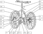
1 is a bicycle having a pair of front wheels having an
2 is a bicycle having a pair of front wheels having an
3 is an
4 is a function of folding and unfolding the front wheel support device of a bicycle and a motorcycle in which the
5 is a bicycle having a pair of front wheels having an
Figure 6 is a structural view of the front wheel support device for a bicycle and a motorcycle provided with a pair of front wheels according to the present invention.
7 is a plan view of a front wheel support device for a bicycle and a motorcycle provided with a pair of front wheels according to the present invention.
FIG. 8 omits the device from the steering arm shaft 210 to the
9 is a folding steering arm 210-3 which operates the
FIG. 10 illustrates a state in which the steering arm 210-3 of the folding steering arm 210-3, which operates the
Figure 11 is provided with a front
12 is provided with the front
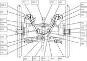
FIG. 13 is an exploded view showing components of the embodiment of FIG. 1 of a bicycle and a motorcycle front wheel supporting device having a pair of front wheels according to the present invention; FIG.
14 is an exploded view showing the main parts of the
15 is an exploded view showing the main part provided with the front
FIG. 16 is an exploded view illustrating main parts provided in the
FIG. 17 is a sectional view showing the main portion of the hub supported by the
FIG. 18 is an exploded view illustrating main parts of the V-shaped steering arm 200-2 in the embodiment of FIG. 3.
19 is an exploded view showing the main portion of the steering arm (200-3) folded in front of the embodiment of Figures 4 and 9.
20 is an exploded view showing the main portion of the steering arm (200-3) folded back from the embodiment of Figures 4 and 11;
Hereinafter, exemplary embodiments of the present invention will be described in detail with reference to the accompanying drawings.
As it is well known, the front wheel supporting apparatus of the bicycle and the motorcycle has a general characteristic of symmetry, and unless otherwise described in the following description and illustration, the opposite side is also the same with only one side description and symbol display.
For convenience of understanding, each connecting part may be provided with a bearing or bushing, or a connector and a lubricating oil inlet for lubrication equivalent thereto, for convenience of understanding, and bolts and nuts for fastening parts of the device. Fasteners equivalent to snap rings, fasteners, washers, etc. may be used.
As shown in Figures 1 to 5, the present invention is rotatably supported by the
According to the present invention, as shown in Figures 1 to 5, the steering
In addition, the steering
The steering arm 200 according to the present invention, as shown in the embodiment of Figures 1, 2 and 5, T-shaped steering arm swing shaft 230-1 and the T-shaped steering arm shaft 210-1 in the middle portion T 5 in the form of a direct connection, or as shown in Figures 1 and 2, when connected via the
In addition, as shown in the embodiment of FIG. 3 and FIG. 18, the steering arm 200 includes a front fixing piece fitted into the center through hole at the front and rear ends of the V-shaped arm swing shaft 220-2 fitted to the lower tube 140 ( 233a) and the
In addition, the steering arm 200 according to the present invention, as shown in the embodiment of Figure 4 and Figures 9 to 10 and 19, the folding steering arm shaft (210-3) is provided with a
On the other hand, the steering arm 200 according to the present invention, as shown in Figures 11 and 12 and 20, when sliding and extending the steering arm swing shaft 210-3 from the rear toward the front, the sliding
The cross-sectional shape of the sliding
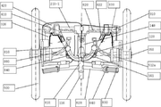
The pivot support 400 according to the present invention, as shown in Figures 1 to 5 and 14, the connecting
The
The connecting
The
The
In addition, the
As shown in FIG. 17, the front
As shown in FIG. 14, the freewheel shaft 340 is fitted to the front
In addition, as shown in FIG. 14, the freewheel shaft 340 has a through hole at the rear end of the
The
The
14, the
On the other hand, when the
In order to smoothly rotate the
In addition, according to the present invention, as shown in FIGS. 1 to 4 and 13, the
In addition, the handle 600, as shown in Figure 5, other than the present invention downwards the insertion groove or the hub shaft support hole of the lower end of the fork-type steering device (120-1) for supporting the front wheel of a commercially available bike Inserted into and fixed to the
In addition, according to the present invention, the braking device 700 is a
The braking
According to the present invention, the shock absorber 800, as shown in Figures 1 and 6 to 7, the weight of the driver and the load of the load acting on the body acts heavily, or the
At this time, the
On the other hand, the shock absorber 800 is provided in the existing fork-type steering shaft 120-1 when using the fork-type steering shaft 120-1 as the
According to the present invention, the shock absorbing material of the rod-shaped
In addition, according to the present invention, the shock absorber 800 is provided in the lower portion of the
On the other hand, according to the present invention, the shock absorber 800 is a
On the other hand, according to the present invention, the shock absorber 800, as shown in Figures 9, 11 and 13, the end of the annular shaft 861 is bent roundly around the hub body axis (310) is a support
In addition, according to the present invention is characterized in that it can be combined with the fastener 242 for the rapid angle adjustment or disassembly and assembly of each part of the frame 100.
It is apparent to those skilled in the art that the present invention is not limited to the described embodiments, and that various modifications and changes can be made without departing from the spirit and scope of the present invention. Therefore, such modifications or variations will have to belong to the claims of the present invention.
110; Steering Support
111; Tip tube
120; Steering shaft
120-1; Fork Steering Shaft
140; Down tube
141; Receptacle
142; Bracket
200; Steering arm
210; Steering arm axis
220; Steering arm pivot
221; Frontal tube
232; Protrusion
233a; Anterior arm fixation
233b; Rear arm fixation
240; Rotating shaft
300; Front wheel support
310; Bodyguard
320; Front wheel support
330; Front wheel support
340: freewheel shaft
341; Freewheel shaft protrusion
343; flange
350; Hub shaft
3400; Pivotal support
410; Rotary ring
420; Connection
430; Lower buffer zone
500; Front wheel
510; Herb
600; handle
610; Handle shaft
620; Handlebar
630; Handle grip
640; Shift handle
700; Braking device
711; Rotor brake
712; V-type brake
720; Brake rotor
730; Braking cable
7740; Braking handle
750; Braking Cable Distribution Port
800; Shock absorber
810; Rod Shock Absorber
820; Heavy tension buffer
820; Axial shock absorber
830; Side tension buffer
841; Upper support arm
851; Suspension
860; Annular buffer
Claims (17)
A handle 600 having a braking handle 740 and a shifting handle 640 on the handle shaft 610 and the handle bar 620 fixedly supported at the upper end of the steering shaft 120; and
The steering arm oscillation shaft 230, which is inserted into the lower tube 140 and rotatably supported, supports the steering arm shaft 210 in the left and right directions so as to rotate the rotation support ring 410 of the rotation support 400 at both ends of the steering arm shaft 210. Steering arm 200 for rotatably supporting; And
The connecting yoke 420 and the rotary ring 410 are fixed to the rotary ring 410 integrally extending in both sides to rotatably support the body hub 310 of the front wheel support 300 to the rear. Rotating support 400 having a lower buffer unit 430 for supporting the shock absorber 800 is extended integrally to the rear;
Front wheel support having a brake fixing piece (314, 331) for supporting the front wheel 500 rotatably extending to the rear of the body hub 310 of the front wheel support 300 to support the brake 710 ( 300); and
A front wheel 500 inserted into the hub shaft 350 on the front wheel support 300 to be rotatably supported;
Braking device 700 having a brake 710, the brake handle 740 provided on the handle 600 is operated via a brake cable 730; and
Bicycle and motor provided with a pair of front wheels, characterized in that it comprises a; shock absorber 800 for buffering the joint motion of each device connected between the steering shaft 120 and the front wheel support stand 330 Front wheel support of the cycle
The steering shaft 120 is provided with a lower support arm 842 in the middle of the fork part 145 and connected to the lower buffer unit 430 via a rod shock absorber 810, and has a lower tube 140 at the lower end thereof. The front wheel support device for a bicycle and a motorcycle provided with a pair of front wheels, characterized in that it comprises a fork-shaped steering shaft (210-1) is supported via the bracket 142 and the hub shaft (143) provided in the.
The steering arm 200 is inserted so that the swing shaft protrusion end 232 provided in the middle of the steering arm swing shaft 220-1 is supported by the front end of the lower tube 140 to fix the rear end with the swing shaft stopper 234. It is rotatably supported, and is provided with a T-shaped steering arm (200-1) coupled to the center portion of the steering arm shaft (210-1) at the front end to support the rotation ring 411 jointly at both ends. A front wheel support device for a bicycle and a motorcycle provided with a pair of front wheels.
The rear end of the V-shaped steering arm shaft 210-2 is fixed to the rear arm fixing piece 233b fixed to the rear end of the steering arm swing shaft 220-2 at the rear of the lower tube 140, The intermediate portion of the V-shaped steering arm shaft 210-2 is fixed to the front arm fixing piece 233a fixed to the front end of the steering arm oscillating shaft 230-2 at the front end of the lower tube 140, and rotates at both ends. A front wheel support device for a bicycle and a motorcycle provided with a pair of front wheels, characterized in that it comprises a V-shaped steering arm (200-2) for supporting joint movement.
The steering arm 200 is inserted so as to contact the front end of the lower tube 140 as the rotating shaft portion 240 is provided with the swing shaft protrusion end 232 provided in the middle portion of the shaft, and has a rear hinge portion 235 at the rear end The front of the oscillation shaft protrusion 232 is a sliding portion 239, and a slider fastener 238 and a slider 236 having steering levers 237 on both sides thereof are fitted, and the front end thereof is the oscillation shaft stopper 234. A hinged hinge hinge 211 of the rear end is connected to the hinges provided at both ends of the fixed folding arm swing shaft 220-3 and the swing shaft hinge portion 235 of the folding arm swing shaft 220-3. The steering arm pivot shaft 220-3 is hinged and connected by a hinge protrusion 211 provided in the middle portion via the steering lever 237 so as to support joint movement, and the rotary ring 410 at the front end thereof. With a folding arm (200-3) having a folding steering arm shaft (210-3) having a rotating shaft portion 212 to rotatably support the Front wheel support device provided with a pair of front wheels, characterized in that.
The steering arm 200 is inserted into the rear end of the lower tube 140 in contact with the swinging shaft projection end 232 as the rotation axis is provided in front of the swinging shaft projection end 232 provided in the middle of the shaft, the front end of the steering arm on both sides It is rotatably supported as a hinge portion 235 having a lever 237, the rear end of the protruding end 232 is a sliding portion 239, a slider having a fastener 242 and a hinge protrusion 211 on both sides. Inserting (236b), the rear end is a folding steering arm swing shaft (220-3) fixed by the swing shaft stopper (234), and the hinge projection provided in the rear and middle portions of the folding steering arm shaft (210-3) ( 211) hinged rear ends to hinge protrusions 211 provided at both ends of the slider 236b of the folding arm swing shaft 220-3, and hinged to an intermediate portion via the steering lever 237. It is supported by the folding arm arm shaft (220-3) folding and joint movement, the rotation ring 410 can be rotated at the tip Front wheel support device provided with a pair of front wheels, characterized in that it comprises a folding arm (200-3) having a folding steering arm shaft (210-3) having a rotating shaft portion (212) to support.
The pivotal support 400 is extended to the outside on the rotary ring 410 and the rotary ring 410 is provided with a through hole rotatably having a front end of the steering arm shaft 210 in the center, the upper and lower through holes in the tip The connecting yoke 420 supporting the body hub shaft 311 of the front wheel support 300 and the linear hub body 510b, and the lower shock absorber 430 are integrally rearward to the rotary ring 810. It can be provided in a curved form to the inside and upwards by avoiding collision with the front wheel support 320 and the steering arm shaft (210-2, 210-3) extending to the left and right joint movement, one end of the shock absorber 800 Front wheel support device for a bicycle and a motorcycle provided with a pair of front wheels, characterized in that for supporting.
The front wheel support 300 is rotatably fitted to the body hub shaft 311 and the body hub shaft 311 supported by the connecting yoke 420 and the hub body 310 to support the upper and lower ends to the connecting yoke 420 and The front wheel support unit 310 and the front wheel fixing unit 340 having the front wheel fixing unit 340 and the rotor type brake fixing unit 321 which are integrally extended on the hub body unit 310 and penetrate through the end portion thereof. The hub shaft which is inserted from the outside and fixed to contact the protruding end 542, the inner end is fixed to the inner side of the freewheel shaft 340 and the inner side of the freewheel shaft 340 to support the hub body stand 510 of the front wheel 500 Front wheel support device for a bicycle and a motorcycle provided with a pair of front wheels, characterized in that the 350 is provided
The front wheel support 300 is rotatably fitted to the body hub shaft 311 and the body hub shaft 311 supported by the connecting yoke 420, the hub body 310 to support the upper and lower ends to the connecting yoke 420 And the front wheel support base 310 and the body hub having a hub wheel 350 and a front wheel fixing portion 340 to which the hub shaft 350 and the flange 343 are integrally extended to penetrate on the hub body belt 310. A clip 331 is provided on a clip fixing part 311z extending up and down the shaft 311 to fix the front end of the front wheel support arm 330, and the front wheel to the hub side clip 337 provided at the rear end. A front wheel support arm 330 that supports an outer end of the hub shaft 354 rotatably supporting 500 and may include a V-shaft brake fixing piece 338 that supports the V-shaft brake 712 at its distal end. The front wheel support device for a bicycle and a motorcycle provided with a pair of front wheels, characterized in that the provided.
The front wheel support arm 330 rotatably supports the outer hub of the hub shaft 354 to the hub side clip 337 provided at the rear end so as to rotatably support the linear hub body 510b, and the V-shaped brake 712 at the front end thereof. The front wheel support device for a bicycle and a motorcycle provided with a pair of front wheels, characterized in that it can be provided with a V-shape brake support piece (338).
The front wheel 500 has a rotor fixing portion 511 to which the hub 512 and the braking rotor 720 are fixed in succession to the hub 512, and the rotor fixing portion 511 to the inside in succession. The hub body stand 510a, which is a hollow shaft having a body shaft 513 that is inserted into the freewheel shaft 350 provided in the front wheel support 300 and is rotatably supported, is inserted into the hub shaft 350 to be rotatably supported. A front wheel support device for a bicycle and a motorcycle provided with a pair of front wheels.
The front wheel 500 is a hub 512b of the wheel is fitted to the hub shaft 350 is fixed to the front wheel support base 320 is fixed to the front wheel support stand 320 and the front wheel support arm 330 is supported hub The front wheel support device for a bicycle and a motorcycle provided with a pair of front wheels, characterized in that the rotation is supported by the shaft (350).
The shock absorber 800 is characterized in that the upper buffer support 840 fixed on the steering shaft 120 is provided with a rod-shaped shock absorber 811 having a buffer action with the lower shock absorber 430. Bicycle and motorcycle front wheel support device provided with a pair of front wheels.
The shock absorber 800 is a tension shock absorber to obtain elasticity by a rod or plate that is bent several times, and supports the center of the lower tube 140 and a heavy tension shock absorber 820 that supports both ends of the lower shock absorber 430. And a front wheel support device for a bicycle and a motorcycle provided with a pair of front wheels.
The shock absorber 800 is a plate-shaped shock absorber folded several times, one end is fixed to the front wheel support (320) with a buffer fixing bolt 831, the other side is fixed to the lower shock absorber 430 (side tension buffer) 820, the front wheel support device for a bicycle and a motorcycle provided with a pair of front wheels.
The buffer device 800 is bent roundly around the body hub shaft 311 is fitted to the buffer member and fixed to one side of the annular shaft 861 and the annular shaft 861 provided with a stopper 863 at the end. And a support hole protrusion end 864 fixed to the inside of the front wheel support stand 320, and an annular support hole 862 and an annular support hole fitted to the annular shaft 861 and supported at an upper portion of the lower buffer stand 430. The front wheel support device for a bicycle and a motorcycle provided with a pair of front wheels, characterized in that it comprises an annular shock absorber (820) having a cushioning material inserted in front and rear of the (862).
The braking device 700 may introduce a braking cable 732 applied from the braking handle to the upper end of the distribution port case 751 having a flow port 752 that can be slid therein, and a cable hose 731. Hose fixing nipple 754 that can be fixed is provided, the middle portion of the braking cable 732 applied to both brakes (711, 712) is drawn in and drawn out to the other side, the cable hose 731 is fixed Two hose fixing nipples 754 are provided, and the flow port 752 has a braking cable distribution port 750 having a cable cradle 753 having a braking cable 732 fixed to the front and rear ends thereof. A front wheel support device for a bicycle and a motorcycle provided with a pair of front wheels.
Priority Applications (1)
| Application Number | Priority Date | Filing Date | Title |
|---|---|---|---|
| KR1020120012783A KR20130101609A (en) | 2012-02-08 | 2012-02-08 | Apparatus supporting a pair of front wheel of bicycles and motorcycles |
Applications Claiming Priority (1)
| Application Number | Priority Date | Filing Date | Title |
|---|---|---|---|
| KR1020120012783A KR20130101609A (en) | 2012-02-08 | 2012-02-08 | Apparatus supporting a pair of front wheel of bicycles and motorcycles |
Publications (1)
| Publication Number | Publication Date |
|---|---|
| KR20130101609A true KR20130101609A (en) | 2013-09-16 |
Family
ID=49451652
Family Applications (1)
| Application Number | Title | Priority Date | Filing Date |
|---|---|---|---|
| KR1020120012783A KR20130101609A (en) | 2012-02-08 | 2012-02-08 | Apparatus supporting a pair of front wheel of bicycles and motorcycles |
Country Status (1)
| Country | Link |
|---|---|
| KR (1) | KR20130101609A (en) |
Cited By (3)
| Publication number | Priority date | Publication date | Assignee | Title |
|---|---|---|---|---|
| WO2015002167A1 (en) * | 2013-07-01 | 2015-01-08 | ヤマハ発動機株式会社 | Vehicle provided with leaning-capable vehicle-body frame and two front wheels |
| CN106476957A (en) * | 2016-08-31 | 2017-03-08 | 郑州锐图汽车设计有限公司 | A kind of front two-wheeled transfer being applied to tricycle |
| CN113056415A (en) * | 2018-09-28 | 2021-06-29 | 比亚乔股份公司 | Front wheel carrier with central shock absorber assembly for a motor vehicle with two front steered wheels and motor vehicle comprising such a front wheel carrier |
-
2012
- 2012-02-08 KR KR1020120012783A patent/KR20130101609A/en active Search and Examination
Cited By (6)
| Publication number | Priority date | Publication date | Assignee | Title |
|---|---|---|---|---|
| WO2015002167A1 (en) * | 2013-07-01 | 2015-01-08 | ヤマハ発動機株式会社 | Vehicle provided with leaning-capable vehicle-body frame and two front wheels |
| US9828056B2 (en) | 2013-07-01 | 2017-11-28 | Yamaha Hatsudoki Kabushiki Kaisha | Vehicle provided with leaning-capable vehicle-body frame and two front wheels |
| CN106476957A (en) * | 2016-08-31 | 2017-03-08 | 郑州锐图汽车设计有限公司 | A kind of front two-wheeled transfer being applied to tricycle |
| CN106476957B (en) * | 2016-08-31 | 2023-08-08 | 浙江朗翔实业有限公司 | Front two-wheel steering device suitable for inverted tricycle |
| CN113056415A (en) * | 2018-09-28 | 2021-06-29 | 比亚乔股份公司 | Front wheel carrier with central shock absorber assembly for a motor vehicle with two front steered wheels and motor vehicle comprising such a front wheel carrier |
| CN113056415B (en) * | 2018-09-28 | 2022-07-08 | 比亚乔股份公司 | Front wheel carrier with central shock absorber assembly for a motor vehicle with two front steered wheels and motor vehicle comprising such a front wheel carrier |
Similar Documents
| Publication | Publication Date | Title |
|---|---|---|
| US10029755B2 (en) | Cycle and associated components | |
| TWI650263B (en) | Three-wheel or more vehicle frame mechanism | |
| JP3196617U (en) | Folding motorcycle | |
| US8739914B2 (en) | Three-wheeled vehicle with steering apparatus configured for enhanced operation during a banking turn | |
| EA008789B1 (en) | Folding bicycle | |
| US10011316B2 (en) | Vehicle with foldable double-wheel assembly | |
| US11130540B2 (en) | Saddle type vehicle | |
| US11130541B2 (en) | Saddle type vehicle | |
| KR20130101609A (en) | Apparatus supporting a pair of front wheel of bicycles and motorcycles | |
| WO2008032969A1 (en) | Trike | |
| US20210009228A1 (en) | Squat bicycle | |
| US8888116B2 (en) | Suspension for handcycle | |
| JP2020050043A (en) | Three-wheel bicycle | |
| TW202248075A (en) | Tilting two wheel front fork assembly for a vehicle | |
| RU2391244C1 (en) | Bicycle | |
| CN219029650U (en) | Single-wheel bicycle | |
| CN219029658U (en) | Folding bicycle | |
| CN210083433U (en) | Foldable tricycle | |
| JP2015067202A (en) | Front wheel suspension device of saddle-riding type vehicle | |
| CN219215268U (en) | Folding bicycle | |
| CN211364812U (en) | Electric vehicle frame and electric vehicle with same | |
| JP6338231B1 (en) | bicycle | |
| CN117549997A (en) | Single-wheel bicycle | |
| CN117644934A (en) | Folding bicycle | |
| CN116001963A (en) | Folding bicycle |
Legal Events
| Date | Code | Title | Description |
|---|---|---|---|
| A201 | Request for examination | ||
| E902 | Notification of reason for refusal | ||
| E601 | Decision to refuse application | ||
| AMND | Amendment | ||
| E801 | Decision on dismissal of amendment |