KR20130071283A - Form for manufacturing block for arch structure, and manufacturing method of block assembly for arch structure - Google Patents
Form for manufacturing block for arch structure, and manufacturing method of block assembly for arch structure Download PDFInfo
- Publication number
- KR20130071283A KR20130071283A KR1020110138694A KR20110138694A KR20130071283A KR 20130071283 A KR20130071283 A KR 20130071283A KR 1020110138694 A KR1020110138694 A KR 1020110138694A KR 20110138694 A KR20110138694 A KR 20110138694A KR 20130071283 A KR20130071283 A KR 20130071283A
- Authority
- KR
- South Korea
- Prior art keywords
- arch
- block
- formwork
- plate
- longitudinal
- Prior art date
Links
- 238000004519 manufacturing process Methods 0.000 title claims abstract description 32
- 238000009415 formwork Methods 0.000 claims abstract description 102
- 238000000034 method Methods 0.000 claims abstract description 6
- 239000004567 concrete Substances 0.000 claims description 24
- 239000004746 geotextile Substances 0.000 claims description 15
- 230000008602 contraction Effects 0.000 claims description 4
- 239000011178 precast concrete Substances 0.000 abstract description 4
- 230000000712 assembly Effects 0.000 abstract description 3
- 238000000429 assembly Methods 0.000 abstract description 3
- 238000010276 construction Methods 0.000 description 7
- 230000003014 reinforcing effect Effects 0.000 description 4
- 239000000835 fiber Substances 0.000 description 2
- 238000005452 bending Methods 0.000 description 1
- 230000015572 biosynthetic process Effects 0.000 description 1
- 230000008878 coupling Effects 0.000 description 1
- 238000010168 coupling process Methods 0.000 description 1
- 238000005859 coupling reaction Methods 0.000 description 1
- 230000007423 decrease Effects 0.000 description 1
- 230000000694 effects Effects 0.000 description 1
- 238000005516 engineering process Methods 0.000 description 1
Images


Classifications
-
- B—PERFORMING OPERATIONS; TRANSPORTING
- B28—WORKING CEMENT, CLAY, OR STONE
- B28B—SHAPING CLAY OR OTHER CERAMIC COMPOSITIONS; SHAPING SLAG; SHAPING MIXTURES CONTAINING CEMENTITIOUS MATERIAL, e.g. PLASTER
- B28B7/00—Moulds; Cores; Mandrels
- B28B7/02—Moulds with adjustable parts specially for modifying at will the dimensions or form of the moulded article
-
- B—PERFORMING OPERATIONS; TRANSPORTING
- B28—WORKING CEMENT, CLAY, OR STONE
- B28B—SHAPING CLAY OR OTHER CERAMIC COMPOSITIONS; SHAPING SLAG; SHAPING MIXTURES CONTAINING CEMENTITIOUS MATERIAL, e.g. PLASTER
- B28B7/00—Moulds; Cores; Mandrels
- B28B7/08—Moulds provided with means for tilting or inverting
- B28B7/082—Tiltable moulding tables or similar moulding surfaces
-
- B—PERFORMING OPERATIONS; TRANSPORTING
- B28—WORKING CEMENT, CLAY, OR STONE
- B28B—SHAPING CLAY OR OTHER CERAMIC COMPOSITIONS; SHAPING SLAG; SHAPING MIXTURES CONTAINING CEMENTITIOUS MATERIAL, e.g. PLASTER
- B28B7/00—Moulds; Cores; Mandrels
- B28B7/26—Assemblies of separate moulds, i.e. of moulds or moulding space units, each forming a complete mould or moulding space unit independently from each other
- B28B7/266—Assemblies of separate moulds, i.e. of moulds or moulding space units, each forming a complete mould or moulding space unit independently from each other for making oblong objects, e.g. girders
-
- E—FIXED CONSTRUCTIONS
- E01—CONSTRUCTION OF ROADS, RAILWAYS, OR BRIDGES
- E01D—CONSTRUCTION OF BRIDGES, ELEVATED ROADWAYS OR VIADUCTS; ASSEMBLY OF BRIDGES
- E01D4/00—Arch-type bridges
-
- E—FIXED CONSTRUCTIONS
- E21—EARTH OR ROCK DRILLING; MINING
- E21D—SHAFTS; TUNNELS; GALLERIES; LARGE UNDERGROUND CHAMBERS
- E21D11/00—Lining tunnels, galleries or other underground cavities, e.g. large underground chambers; Linings therefor; Making such linings in situ, e.g. by assembling
- E21D11/04—Lining with building materials
- E21D11/08—Lining with building materials with preformed concrete slabs
- E21D11/086—Methods of making concrete lining segments
Landscapes
- Engineering & Computer Science (AREA)
- Manufacturing & Machinery (AREA)
- Chemical & Material Sciences (AREA)
- Ceramic Engineering (AREA)
- Mechanical Engineering (AREA)
- Moulds, Cores, Or Mandrels (AREA)
Abstract
본 발명은 프리캐스트 콘크리트로 제작되는 복수개의 아치블록을 종방향으로 연결하여 블록 조립체를 제작한 후, 블록 조립체를 아치 형상이 되도록 배치하여 아치구조물을 완성함에 있어서, 최종적으로 완성하려는 아치구조물의 규모에 맞추어서 각각의 아치블록의 크기와 형상을 변화시켜서 아치블록을 제작할 수 있도록 구성한 거푸집장치 및 이를 이용한 아치구조물 형성용 블록 조립체의 제작방법에 관한 것이다.
본 발명에서는 바닥거푸집판(10)과; 종측면 경사거푸집판(20)과; 횡측면 거푸집판(30)과; 상기 종측면 경사거푸집판(20)을 종방향으로 이동시킴과 동시에 종측면 경사거푸집판(20)의 기울어진 정도를 조절하는 경사이동 조절부재(40)를 포함하여 구성되어, 경사이동 조절부재(40)의 경사연결판(41)과 종측면 경사거푸집판(20)의 위치와 기울어진 각도를 조절하여, 아치블록(100)의 형상을 필요에 맞게 제작하는 것을 특징으로 하는 거푸집장치 및 아치구조물 형성용 블록 조립체의 제작방법이 제공된다. According to the present invention, after manufacturing a block assembly by connecting a plurality of arch blocks made of precast concrete in the longitudinal direction, and arranging the block assemblies to have an arch shape, in completing the arch structure, the scale of the arch structure to be finally completed In accordance with the present invention relates to a formwork apparatus and a method for manufacturing a block assembly for forming an arch structure using the same to be configured to manufacture the arch block by changing the size and shape of each arch block.
In the present invention, the bottom formwork plate 10; A longitudinal side slope formwork plate 20; Transverse side formwork plate 30; The inclined movement adjusting member 40 is configured to move the longitudinal inclined formwork plate 20 in the longitudinal direction and to adjust the degree of inclination of the longitudinal inclined formwork plate 20. Forming apparatus and arch structure, characterized in that to form the shape of the arch block 100 to meet the needs, by adjusting the position and inclination angle of the inclined connecting plate 41 and the longitudinal side inclined formwork plate 20 of 40 A method of making a forming block assembly is provided.

Description
본 발명은 아치구조물 형성용 아치블록의 거푸집장치 및 이를 이용한 아치구조물 형성용 블록 조립체의 제조방법에 관한 것으로서, 구체적으로는 프리캐스트 콘크리트로 제작되는 복수개의 아치블록을 종방향으로 연결하여 블록 조립체를 제작한 후, 블록 조립체를 아치 형상이 되도록 배치하여 아치구조물을 완성함에 있어서, 최종적으로 완성하려는 아치구조물의 규모에 맞추어서 각각의 아치블록의 크기와 형상을 변화시켜서 아치블록을 제작할 수 있도록 구성한 거푸집장치 및 이를 이용하여 아치블록을 제작하고 이러한 아치블록에 의해 이루어지는 아치구조물 형성용 블록 조립체의 제조방법에 관한 것이다. The present invention relates to a formwork apparatus for forming arch structures for arch structures and a method for manufacturing a block assembly for forming arch structures using the same. Specifically, a block assembly is connected by longitudinally connecting a plurality of arch blocks made of precast concrete. After fabrication, in order to complete the arch structure by arranging the block assembly to have an arch shape, formwork apparatus configured to manufacture the arch block by changing the size and shape of each arch block in accordance with the size of the arch structure to be finally completed And it relates to a method for producing a block assembly for forming the arch structure made by using the arch block using the same.
상향으로 볼록하게 구부러진 아치구조물은 교량이나 중,소규모의 개착식 터널로 활용되고 있다. 아래에서 선행기술문헌으로 언급하고 있는 국내 등록특허 제10-943044호에는 사각형 단면을 가지도록 프리캐스트 콘크리트로 제작된 복수개의 블록을 종방향으로 일렬 배열하되 연결부재를 이용하여 복수개의 블록을 일체화시켜 하나의 구조체가 되도록 공장에서 복수개의 블록 조립체를 제작한 후, 이러한 블록 조립체를 현장으로 이송하여 크레인 등으로 인양하여 아치 형상으로 배치함으로써 아치 구조물을 시공하는 기술이 소개되어 있다. Upward convex arch structures are used as bridges or as small, medium scale tunnels. In Korean Patent No. 10-943044, which is referred to as a prior art document below, a plurality of blocks made of precast concrete to have a rectangular cross section is arranged in a row in the longitudinal direction, and a plurality of blocks are integrated using a connecting member. After manufacturing a plurality of block assemblies in a factory to be a structure, and then transfer the block assembly to the site and lifted with a crane or the like to arrange the arch structure is introduced technology.
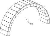
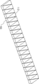
도 1에는 이러한 아치구조물의 시공에 이용되는 블록 조립체(110)가 아치형상으로 구부러져 있는 상태를 보여주는 개략적인 사시도가 도시되어 있고, 도 2에는 도 1에 도시된 블록 조립체(110)를 수평하게 펼친 상태를 보여주는 개략적인 사시도가 도시되어 있다. 도면에 도시된 것처럼, 블록 조립체(110)는 프리캐스트 콘크리트로 제작된 복수개의 아치블록이 일렬로 연속배치되어 서로 연결되는 형태로 구성되며, 도 1에 도시된 것처럼 상향으로 볼록하게 구부러져 아치형태를 이룬 상태에서 교량 등의 아치구조물을 이루게 된다. 이와 같이 블록 조립체가 상향으로 구부러져 아치형태를 이루기 위해서는, 블록 조립체를 구성하는 각각의 아치블록은 한 면이 사각형으로 이루어진 육면체로 이루어지되, 블록 조립체의 길이 방향으로 상면의 폭보다 하면의 폭이 더 작은 형태의 하향 테이퍼진 형상을 가져야 한다. FIG. 1 is a schematic perspective view showing a state in which a
도 3에는 블록 조립체를 이루는데 이용되는 아치블록(100)의 개략적인 사시도가 도시되어 있는데, 도 3에서 화살표 A-A방향 즉, 아치블록(100)이 복수개로 연결되어 블록 조립체를 형성하였을 때 블록 조립체가 길게 연장되는 블록 조립체의 길이방향을 편의상 "종방향"이라고 기재하고, 이에 수직한 방향을 "횡방향"이라고 기재한다. 도면에 도시된 것처럼 상기 아치블록(100)에서 종방향 측면(103, 104)은 아래로 갈수록 서로 가까워지도록 수직선으로부터 각도 θ만큼 경사진 면으로 이루어지며, 그에 따라 아치블록(100)의 상면(101)에서의 종방향 폭은, 하면(102)의 종방향 폭보다 더 크다. 따라서 도 3에 도시된 것처럼, 아치블록(100)은, 종방향으로 상면(101)의 폭보다 하면(102)의 폭이 더 작은 형태의 하향 테이퍼진 형상을 가지게 되는 것이다. 도 3에서 부재번호 113은 아치블록(100)을 연속하여 배치하고, 연속된 아치블록(100)의 상면에 피복콘크리트를 타설하여 블록 조립체(110)를 제작할 때 아치블록(100)과 피복콘크리트 간의 결합을 위하여 아치블록(100)의 상면에 설치하는 매립철근(113)이다. FIG. 3 is a schematic perspective view of the
그런데 아치블록(100)에서 종방향 측면(103, 104)이 경사진 각도 θ가 달라짐에 따라 블록 조립체가 구부러져 만드는 아치형상의 길이 및 상향 굴곡된 높이 등이 달라진다. 즉, 교량 등의 블록 조립체에 의해 만들어진 종국적인 구조물의 길이, 상향 굴곡된 높이 등에 맞추어서 아치블록(100)에서 종방향 측면(103, 104)의 경사진 각도 θ를 조절하여 아치블록(100)을 제작하여야 하는 것이다. 물론 경사진 각도 θ 뿐만 아니라 아치블록(100)의 상면(101)과 하면(102)이 가지는 종방향의 폭도 달라진다. However, as the angle θ of the
또한 이러한 블록 조립체에는 많은 개수의 아치블록이 사용되며, 교량의 폭이나 터널의 길이 등과 같이 아치구조물의 규모에 따라, 구조물의 구축에는 많은 개수의 블록 조립체가 사용되므로, 실제 아치구조물을 시공하기 위해서는 상당히 많은 개수의 아치블록이 이용된다. 따라서 아치블록을 정교하게 동일하고 균일한 형상으로 제작하면서도 많은 개수를 신속하게 제작하는 것이, 아치구조물의 시공기간을 단축하는데 매우 중요하다. In addition, a large number of arch blocks are used for such a block assembly, and according to the size of the arch structure such as the width of the bridge or the length of the tunnel, a large number of block assemblies are used to construct the structure. A significant number of archblocks are used. Therefore, it is very important to shorten the construction period of the arch structure, while manufacturing the arch block in a precisely identical and uniform shape while producing a large number.
본 발명은 위와 같이 복수개의 아치블록을 이용하여 블록 조립체를 제작한 후, 이러한 블록 조립체를 이용하여 교량, 터널 등의 아치구조물을 시공함에 있어서, 목표로 하는 아치구조물의 형상에 맞추어서 아치블록의 형상(아치블록의 길이, 정면과 배면의 경사각도 등)을 용이하게 조절할 수 있으며, 더 나아가 많은 개수의 아치블록을 동일한 형상으로 신속하게 제작할 수 있도록 함으로써, 궁극적으로는 아치구조물의 신속시공이 가능하게 만드는 것을 목적으로 한다,
The present invention after manufacturing a block assembly using a plurality of arch blocks as described above, in the construction of arch structures, such as bridges, tunnels using such a block assembly, the shape of the arch block in accordance with the shape of the target arch structure (The length of the arch block, the inclination angle of the front and the back) can be easily adjusted, and furthermore, it is possible to quickly manufacture a large number of arch blocks in the same shape, thereby ultimately enabling the rapid construction of the arch structure. For the purpose of making,
위와 같은 과제를 달성하기 위하여 본 발명에서는, 종방향으로 상면의 폭보다 하면의 폭이 더 작은 형태의 하향 테이퍼진 형상을 가지며, 복수개로 연결되어 아치구조물 형성용 블록 조립체를 이루는 아치블록의 제작을 위한 거푸집장치로서, 아치블록의 하면을 형성하는 바닥거푸집판과; 상기 바닥거푸집판 위에 설치되어 아치블록의 경사진 종방향 측면을 형성하게 되는 종측면 경사거푸집판과; 상기 바닥거푸집판 위에 설치되어 아치블록의 횡방향 측면을 형성하게 되는 횡측면 거푸집판과; 상기 종측면 경사거푸집판을 종방향으로 이동시킴과 동시에 종측면 경사거푸집판의 기울어진 정도를 조절하는 경사이동 조절부재를 포함하여 구성되며; 상기 경사조절부재는, 상기 종측면 경사거푸집판과 결합하게 되며 기울어지는 정도가 조절되는 경사연결판과, 상기 경사연결판의 배면에서 상기 경사연결판을 지지하는 경사신축봉과, 상기 경사신축봉 및 상기 경사연결판을 종방향으로 이동시킬 수 있는 이동부재와, 상기 이동부재가 가이드되면서 이동하게 되며 상기 경사연결판의 하단이 놓이게 되고 아치블록의 하면 일부를 형성하게 되는 바닥레일부재를 포함하여 구성되어; 상기 이동부재의 이동과 경사신축봉의 신축에 의해 경사연결판과 종측면 경사거푸집판의 위치와 기울어진 각도를 조절하여, 아치블록을 제작하게 되는 것을 특징으로 하는 거푸집장치가 제공된다. In order to achieve the above object, in the present invention, the width of the lower surface than the width of the upper surface in the longitudinal direction has a shape of a downward tapered shape, the production of the arch block forming a block assembly for forming a plurality of arch structures connected to a plurality A formwork apparatus for, comprising: a bottom formwork plate forming a lower surface of an arch block; A longitudinal side slope form plate installed on the bottom form plate to form an inclined longitudinal side surface of the arch block; A transverse side form plate installed on the bottom formwork plate to form a transverse side surface of the arch block; An inclined movement adjusting member which moves the longitudinal inclined formwork plate in the longitudinal direction and simultaneously adjusts the inclination degree of the longitudinal inclined formwork plate; The inclination adjusting member, the inclined connecting plate is coupled to the longitudinal side inclined form plate and the degree of inclination is adjusted, the inclined stretch bar for supporting the inclined connecting plate on the back of the inclined connecting plate, the inclined stretch bar and It comprises a moving member that can move the inclined connecting plate in the longitudinal direction, and the moving member is guided to move while the bottom of the inclined connecting plate is placed and the bottom rail member to form a part of the lower surface of the arch block Became; Forming apparatus is provided by adjusting the position and inclination angle of the inclined connecting plate and the longitudinal side inclined form plate by the movement of the movable member and the expansion and contraction of the inclined stretch bar.
또한 본 발명에서는, 종방향으로 상면의 폭보다 하면의 폭이 더 작은 형태의 하향 테이퍼진 형상을 가지는 아치블록이 복수개로 일렬로 배치되어 서로 연결되어 있는 구성의 아치구조물 형성용 블록 조립체의 제작방법으로서, 상기한 본 발명에 따른 거푸집장치를 복수개가 서로 이웃하도록 일렬로 배치하고; 일렬로 배치된 복수개의 상기 거푸집장치에 콘크리트를 타설하며; 타설된 콘크리트의 상면에는, 복수개의 거푸집장치 전체에 대해 연속하는 토목섬유를 배치한 후, 상기 토목섬유 위로 피복콘크리트를 타설하며; 거푸집장치에 타설된 콘크리트의 양생이 완료되어 복수개의 아치블록이 제작되면, 상기 복수개의 거푸집장치를 아치블록으로부터 탈형함으로써, 복수개의 아치블록을 제작과 동시에 일렬로 배치시켜 하나의 블록 조립체로 형성하게 하는 것을 특징으로 하는 아치구조물 형성용 블록 조립체의 제작방법이 제공된다. In addition, in the present invention, a method of manufacturing a block assembly for forming an arch structure having a configuration in which a plurality of arch blocks having a downward tapered shape in a longitudinal direction having a width smaller than a width of an upper surface thereof are arranged in a row and connected to each other. As the formwork apparatus according to the present invention described above, a plurality of the formwork apparatus is arranged in a line so as to neighbor each other; Placing concrete in a plurality of said formwork devices arranged in a line; On the upper surface of the poured concrete, a continuous geosynthetic fiber is disposed for the entire plurality of formwork devices, and then the coated concrete is poured onto the geotextile; When curing of the concrete poured in the formwork is completed and a plurality of arch blocks are manufactured, the plurality of formwork devices are demolded from the arch blocks, so that the plurality of arch blocks are arranged in a row at the same time as a block assembly to form a block assembly. Provided is a method of manufacturing a block assembly for forming an arch structure.
또한 본 발명에서는 위에서 설명한 구성을 가지는 거푸집장치를, 제작하고자 하는 아치블록의 형상에 맞추어서 크기 및 형상을 조정한 후에, 거푸집장치 내에 콘크리트를 타설하고, 타설된 콘크리트의 양생이 완료되면 거푸집장치를 탈형하여 아치블록을 제작하는 과정을 반복하여, 종방향으로 상면의 폭보다 하면의 폭이 더 작은 형태의 하향 테이퍼진 형상을 가지는 복수개의 아치블록을 제작하고; 제작된 복수개의 아치블록을 일렬로 연속되도록 배치한 후, 복수개의 아치블록의 상면에는, 복수개의 아치블록에 대해 연속하는 토목섬유를 배치한 후, 상기 토목섬유 위로 피복콘크리트를 타설함으로써; 복수개의 아치블록이 일렬로 배치되어 서로 연결되어 있는 하나의 블록 조립체를 제작하게 되는 것을 특징으로 하는 아치구조물 형성용 블록 조립체의 제작방법이 제공된다. In addition, in the present invention, after adjusting the size and shape according to the shape of the arch block to be manufactured, the formwork having the configuration described above, cast concrete in the formwork, and when the curing of the poured concrete is completed, the formwork is demoulded Repeating the manufacturing process of the arch block to produce a plurality of arch blocks having a downward tapered shape having a width smaller in width than the width of the upper surface in the longitudinal direction; After arranging the plurality of arch blocks to be arranged in a row, on the upper surface of the plurality of arch blocks, by placing a continuous geosynthetic fiber for the plurality of arch blocks, by pouring the coated concrete over the geotextiles; Provided is a method of manufacturing a block assembly for forming an arch structure, characterized in that a plurality of arch blocks are arranged in a line to produce one block assembly connected to each other.
본 발명의 거푸집장치에 의하면, 종방향으로 상면의 폭보다 하면의 폭이 더 작은 형태의 하향 테이퍼진 형상을 가지며, 복수개로 연결되어 아치구조물 형성용 블록 조립체를 이루는 아치블록을 제작함에 있어서, 아치블록의 종방향 크기와, 종방향 측면의 경사진 각도를 원하는 형태로 신속하게 변화시키면서 아치블록을 제작할 수 있게 된다. According to the formwork of the present invention, in the longitudinal direction has a downward tapered shape of the shape of the lower surface is smaller than the width of the upper surface, in the manufacture of the arch block forming a block assembly for forming the arch structure, the arch It is possible to fabricate an arch block while quickly changing the longitudinal size of the block and the inclined angle of the longitudinal side to the desired shape.
따라서 블록 조립체를 이용하여 교량, 터널 등의 아치구조물을 시공함에 있어서, 목표로 하는 아치구조물의 형상에 맞추어서 아치블록의 형상을 용이하게 조절할 수 있게 되며, 더 나아가 많은 개수의 아치블록을 동일한 형상으로 신속하게 제작할 수 있게 되어, 아치구조물의 신속시공이 가능하게 되는 효과가 발휘된다. Therefore, in the construction of arch structures such as bridges and tunnels using the block assembly, it is possible to easily adjust the shape of the arch block according to the shape of the target arch structure, and furthermore, a large number of arch blocks in the same shape Being able to manufacture quickly, the effect that enables the rapid construction of the arch structure is exhibited.
도 1은 아치구조물의 시공에 이용되는 블록 조립체가 아치형상으로 구부러져 있는 상태를 보여주는 개략적인 사시도이다.
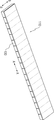
도 2는 도 1에 도시된 블록 조립체를 수평하게 펼친 상태를 보여주는 개략적인 사시도이다.
도 3은 블록 조립체를 이루는데 이용되는 아치블록의 개략적인 사시도이다.
도 4는 본 발명의 제1실시예에 따른 아치블록 제작용 거푸집장치의 개략적인 사시도이다.
도 5는 아치블록의 횡방향 측면을 형성하기 위한 횡측면 거푸집판을 생략하여 본 발명의 제1실시예에 따른 아치블록 제작용 거푸집장치를 도시한 개략적인 사시도이다.
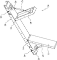
도 6은 본 발명의 거푸집장치에 구비된 경사이동 조절부재의 개략적인 사시도이다.
도 7은 본 발명의 거푸집장치에 구비된 횡측면 거푸집판의 일 실시예에 대한 개략적인 사시도이다.
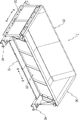
도 8a는 본 발명의 제2실시예에 따른 거푸집장치의 개략적인 사시도이다.
도 8b는 도 8a에 도시된 거푸집장치에 의해 제작되는 아치블록의 개략적인 사시도이다.
도 9는 본 발명의 거푸집장치를 이용하여 제작된 아치블록을 종방향으로 나란하게 나열한 상태를 보여주는 개략적인 사시도이다.
도 10은 도 9에 도시된 상태에 후속하여 길게 나열된 복수개의 아치블록(100) 상면에 토목섬유를 연속적으로 배치한 상태를 보여주는 개략적인 사시도이다.
도 11은 도 10에 도시된 상태에 후속하여 복수개의 아치블록 위에 피복콘크리트를 타설한 상태를 보여주는 개략적인 사시도이다. 1 is a schematic perspective view showing a state in which a block assembly used for construction of an arch structure is bent into an arch shape.
Figure 2 is a schematic perspective view showing the block assembly shown in Figure 1 horizontally expanded.
Figure 3 is a schematic perspective view of an arch block used to make a block assembly.
Figure 4 is a schematic perspective view of the formwork apparatus for producing arch blocks according to the first embodiment of the present invention.
Figure 5 is a schematic perspective view showing the formwork apparatus for producing an arch block according to the first embodiment of the present invention by omitting the lateral formwork plate to form a transverse side of the arch block.
Figure 6 is a schematic perspective view of the inclined movement adjusting member provided in the formwork of the present invention.
Figure 7 is a schematic perspective view of one embodiment of a lateral formwork plate provided in the formwork device of the present invention.
8A is a schematic perspective view of a formwork apparatus according to a second embodiment of the present invention.
FIG. 8B is a schematic perspective view of the arch block manufactured by the formwork shown in FIG. 8A.
Figure 9 is a schematic perspective view showing a state arranged side by side in the longitudinal direction arch blocks produced using the formwork of the present invention.
FIG. 10 is a schematic perspective view illustrating a state in which geotextiles are continuously disposed on the upper surfaces of the plurality of
FIG. 11 is a schematic perspective view illustrating a state in which coated concrete is poured on a plurality of arch blocks subsequent to the state shown in FIG. 10.
이하, 본 발명의 바람직한 실시예를 첨부한 도면을 참조하여 설명한다. 본 발명은 도면에 도시된 실시예를 참고로 설명되었으나 이는 하나의 실시예로서 설명되는 것이며, 이것에 의해 본 발명의 기술적 사상과 그 핵심 구성 및 작용이 제한되지 않는다. Hereinafter, preferred embodiments of the present invention will be described with reference to the accompanying drawings. Although the present invention has been described with reference to the embodiments shown in the drawings, it is to be understood that the technical idea of the present invention and its essential structure and operation are not limited thereby.
도 4에는 본 발명의 제1실시예에 따른 아치블록 제작용 거푸집장치(1)(이하, "거푸집장치(1)"라고 약칭함)의 개략적인 사시도가 도시되어 있고, 도 5에는 설명을 위하여 아치블록(1)의 횡방향 측면을 형성하기 위한 횡측면 거푸집판(30)을 생략하여 도시한 거푸집장치(1)의 개략적인 사시도가 도시되어 있다. FIG. 4 is a schematic perspective view of a
도면에 도시된 것처럼, 본 발명에 따른 거푸집장치(1)는 도 3에 도시된 것과 같이, 종방향으로 상면(101)의 폭보다 하면(102)의 폭이 더 작은 형태의 하향 테이퍼진 형상을 가지는 아치블록(100)을 제작하기 위한 것으로서, 아치블록(100)의 하면(102)을 형성하는 바닥거푸집판(10)과, 상기 바닥거푸집판(10) 위에 설치되어 아치블록(100)의 경사진 종방향 측면(103, 104)을 형성하게 되는 종측면 경사거푸집판(20)과, 상기 바닥거푸집판(10) 위에 설치되어 아치블록(100)의 횡방향 측면을 형성하게 되는 횡측면 거푸집판(30)과, 상기 종측면 경사거푸집판(20)을 종방향으로 이동시킴과 동시에 종측면 경사거푸집판(20)의 기울어진 정도를 조절하는 경사이동 조절부재(40)를 포함하여 구성된다. As shown in the figure, the
우선 바닥거푸집판(10)부터 살펴보면, 바닥거푸집판(10)은 아치블록(100)의 하면(102)을 형성하는 부재로서, 아치블록(100)의 횡방향 크기에 맞추어서 복수개의 판부재로 조립되어 구성될 수 있다. 종측면 경사거푸집판(20)은 아치블록(100)의 경사진 종방향 측면(103, 104)을 형성하게 되는 부재로서, 종측면 경사거푸집판(20) 역시 아치블록(100)의 횡방향 크기에 맞추어서 복수개의 판부재로 조립되어 구성될 수 있다. First, from the
상기 종측면 경사거푸집판(20)의 횡방향 양측에는 각각 경사이동 조절부재(40)가 설치되어 결합된다. 도 6에는 경사이동 조절부재(40)의 개략적인 사시도가 도시되어 있는데, 상기 경사조절부재(40)는, 앞서 설명한 종측면 경사거푸집판(20)과 결합하게 되며 기울어지는 정도가 조절되는 경사연결판(41)과, 상기 경사연결판(41)의 배면에서 상기 경사연결판(41)을 지지하는 경사신축봉(42)과, 상기 경사신축봉(42) 및 상기 경사연결판(41)을 종방향으로 이동시킬 수 있는 이동부재(43)와, 상기 이동부재(43)가 가이드되면서 이동하게 되며 상기 경사연결판(41)의 하단이 놓이게 되고 아치블록(100)의 하면(102) 일부를 형성하게 되는 바닥레일부재(45)를 포함하여 구성된다. On both sides of the longitudinal side
구체적으로 바닥레일부재(45)는 평평한 상면을 가지는 부재로서 횡방향(도 4의 화살표 B-B 방향)으로 상기 바닥거푸집판(10)의 양단에 각각 결합되어 배치된다. 상기 바닥레일부재(45)에는 이동부재(43)가 조립되어 있는데, 상기 바닥레일부재(45)에서 종방향으로 간격을 두고 양측으로 이동부재(43)가 설치되어 있는 것이다. Specifically, the
상기 이동부재(43)는 바닥레일부재(45)를 따라 종방향(도 4의 화살표 A-A 방향)으로 이동된다. 물론 이동된 후에는 볼트 등의 체결수단(46)에 의해 이동부재(43)가 바닥레일부재(45)에 고정된다. 상기 이동부재(43)에는 경사신축봉(42)의 하단이 회전가능하게 결합되어 있을 뿐만 아니라, 상기 이동부재(43)에는 회전힌지(44)에 의해 경사연결판(41)의 하단이 회전가능하게 결합되어 있다. 상기 경사신축봉(42)은 신축이 가능한 부재로서 그 상단은 경사연결판(41)의 배면에 회전가능하게 결합되어 있다. 상기 경사연결판(41)은 도 5에 도시된 것처럼 그 측면이 상기 종측면 경사거푸집판(20)의 횡방향 양측에 결합된다. The moving
이와 같은 구성에서, 경사신축봉(42)은 그 길이가 신축될 수 있는 구성을 가지고 있으므로, 경사신축봉(42)의 길이가 증가되면 경사연결판(41)은 하단의 회전힌지(44)를 중심으로 회전하면서 점점 수직하게 세워지게 되어 종방향 경사거푸집판(20)도 수직하게 세워지게 되며 결국 이러한 본 발명의 거푸집장치(1)에 의해 제작되는 아치블록(100)에서의 경사진 각도 θ가 줄어들게 된다. 반대로 경사신축봉(42)의 길이가 줄어들면 경사연결판(41)이 점점 뉘어져 기울어지게 되어 종방향 경사거푸집판(20)도 기울어져 뉘어지고, 그에 따라 본 발명의 거푸집장치(1)에 의해 제작되는 아치블록(100)에서의 경사진 각도 θ가 증가된다. In such a configuration, since the inclined
한편, 상기 이동부재(43)는 바닥레일부재(45)를 따라 종방향으로 이동되도록 바닥레일부재(45)에 설치되므로, 상기 바닥레일부재(45)에서 종방향으로 간격을 두고 양측으로 설치된 상기 이동부재(43)가 서로 멀어지는 방향으로 이동하게 되면, 이동부재(43)에 하단이 회전가능하게 결합되어 있는 경사연결판(41)도 이동부재(43)와 함께 이동하게 되고, 그에 따라 서로 종방향으로 마주하고 있는 경사연결판(41) 사이의 간격도 벌어지게 된다. 물론 경사연결판(41)과 결합되어 있는 종방향 경사거푸집판(20)도 함께 이동하여 마주하고 있는 종방향 경사거푸집판(20) 사이도 벌어지게 된다. 결과적으로 본 발명의 거푸집장치(1)에 의해 제작되는 아치블록(100)의 종방향 폭이 커지는 것이다. 이동부재(43)가 반대로 이동하게 되면, 경사연결판(41) 및 종방향 경사거푸집판(20)도 함께 이동하게 되어, 서로 마주하고 있는 종방향 경사거푸집판(20) 사이의 간격이 줄어들게 되어 본 발명의 거푸집장치(1)에 의해 제작되는 아치블록(100)의 종방향 폭이 줄어들게 된다. On the other hand, since the
이와 같이, 본 발명의 거푸집장치(1)에서는 경사이동 조절부재(40)를 구비하여, 서로 마주하고 있는 종방향 경사거푸집판(20)의 기울어진 각도 및 사이 간격을 매우 용이하고 신속하게 변화시킬 수 있다. 따라서 본 발명의 거푸집장치(1)를 이용하게 되면, 아치블록(100)의 종방향 크기와, 종방향 측면(102, 103)의 경사진 각도를 원하는 형태로 신속하게 변화시키면서 아치블록(100)을 제작할 수 있게 된다. Thus, in the
아치구조물의 시공에 적합한 아치블록(100)의 종방향 폭 크기와 종방향 측면(102, 103)의 경사각도가 되도록 이동부재(43) 및 경사신축봉(42)을 조절하여, 바닥거푸집판(10)에 상기 경사이동 조절부재(40) 및 종방향 경사거푸집판(20)을 조립한 후에는 아치블록(100)의 횡방향 측면을 형성하게 되는 횡측면 거푸집판(30)을 설치한다. 도 4에 도시된 것처럼, 횡방향으로 개방된 측면을 마감하도록 경사이동 조절부재(40)의 횡방향 외측에 횡측면 거푸집판(30)을 배치하고, 지그장치를 이용하여 고정시키는 것이다. By adjusting the
도 7에는 횡측면 거푸집판(30)의 일 실시예에 대한 개략적인 사시도가 도시되어 있는데, 상기 횡측면 거푸집판(30) 역시 복수개의 판부재를 조립하여 하나의 부재로 제작될 수 있는데, 특히, 높이 조절판(32)을 더 구비하여, 상기 높이 조절판(32)의 갯수를 변화시킴으로써 용이하게 거푸집판(30)의 높이를 필요에 맞추어서 조절할 수 있다. 특히, 도 7에 도시된 것처럼, 횡측면 거푸집판(30)의 하부에 힌지부(33)을 형성하여 힌지부(33)의 위쪽 부분이 외측으로 회전될 수 있도록 구성하게 되면, 후술하는 것처럼 거푸집장치(1)에 콘크리트를 타설하여 양생시킨 후에, 횡측면 거푸집판(30)을 탈형하지 않고, 단지 힌지부(33)의 위쪽 부분만을 회전킴으로써 양생된 아치블록의 횡측면으로부터 분리시킬 수 있게 된다. 따라서 이와 같은 힌지부(33)를 구비한 횡측면 거푸집판(30)을 이용하게 되면, 거푸집장치(1)의 조립 및 탈형 과정이 단순화되므로 아치블록의 생산성이 더욱 향상되는 효과가 발휘된다. 7 is a schematic perspective view of an embodiment of a
한편, 도 8a에는 본 발명의 제2실시예에 따른 거푸집장치(1)의 개략적인 사시도가 도시되어 있고, 도 8b에는 도 8a에 도시된 거푸집장치(1)에 의해 제작된 아치블록(100)의 일예에 대한 개략적인 사시도가 도시되어 있다. 도 8a에 도시된 실시예는 아치블록(100)에 횡방향으로 철근이 노출되는 경우에 맞추어서 변형된 것이다. 즉, 도 8b에 도시된 것처럼 아치블록(100)에서 횡방향 측면에 루프형 철근(109)이 돌출되어 노출될 필요가 존재할 수 있다. 이 경우에는 도 8a에 도시된 것처럼, 횡측면 거푸집판(30)에 루프형 철근(109)이 관통할 수 있는 철근 관통공(31)을 형성하게 된다. Meanwhile, FIG. 8A shows a schematic perspective view of the
위에서 살펴본 구성과 과정을 통해 거푸집장치(1)의 조립이 완성되면 거푸집장치(1)에 콘크리트를 타설하고, 탈형이 가능할 정도로 콘크리트가 경화되면 콘크리트로부터 거푸집장치(1)를 탈형한다. 거푸집장치(1)를 조립하는 순서와 반대로, 횡측면 거푸집판(30)을 분리하여 제거하고, 이동부재(43)를 이동시키거나 또는 경사신축봉(42)을 수축시켜 종방향 경사거푸집판(20)을 콘크리트부재 즉, 아치블록(100)으로부터 멀어지게 하여 아치블록(100)으로부터 거푸집장치(1)가 분리되도록 함으로써 아치블록(100)을 제작하게 된다. 이와 같이 본 발명의 거푸집장치(1)에서는 탈형시에도 경사신축봉(42)의 수축 또는 이동부재(43)의 이동에 의해 용이하게 아치블록(100)을 거푸집장치(1)로부터 분리시킬 수 있게 된다. When the assembly of the
다음에서는 아치블록(100)을 이용하여 블록 조립체(110)를 제작하는 방법에 대해 설명한다. Next, a method of manufacturing the
도 9에는 본 발명의 거푸집장치(1)를 이용하여 제작된 아치블록(100)을 종방향으로 나란하게 나열한 상태를 보여주는 개략적인 사시도가 도시되어 있고, 도 10에는 도 9에 도시된 상태에 후속하여 길게 나열된 복수개의 아치블록(100) 상면에 토목섬유(112)를 연속적으로 배치한 상태를 보여주는 개략적인 사시도가 도시되어 있으며, 도 11에는 도 10에 도시된 상태에 후속하여 아치블록(100)의 상면에 구비된 매립철근(113)과 상기 토목섬유(112)가 매립되도록 복수개의 아치블록(100) 위에 피복콘크리트를 타설한 상태를 보여주는 개략적인 사시도가 도시되어 있다. 구체적으로 도 9에 도시된 것처럼, 본 발명의 거푸집장치(1)를 이용하여 제작된 아치블록(100)을 종방향으로 나란하게 연속하여 나열하고, 그 위로는 도 10에 도시된 것처럼 토목섬유(112)를 연속적으로 배치한다. 그리고 도 11에 도시된 것처럼, 복수개의 아치블록(100) 위에 피복콘크리트를 타설하여 아치블록(100)의 상면에 구비된 매립철근(113)과 상기 토목섬유(112)가 상기 피복콘크리트에 매립되도록 함으로써, 복수개의 아치블록(100)이 토목섬유(112)에 의해 서로 연결되어 하나의 블록 조립체(110)를 이루게 되는 것이다. 위와 같이 블록 조립체(110)를 제작함에 있어서, 복수개의 아치블록(100)을 일체화시키는 토목섬유(112)로는 흔히 지오그리드라고 불리는 것을 사용할 수 있는데, 이에 한정되지 아니하며 강선망(wire mesh) 등도 토목섬유(112)로 사용될 수 있다.FIG. 9 is a schematic perspective view showing a state in which the arch blocks 100 manufactured using the
한편, 위의 설명에서는 본 발명에 따른 거푸집장치(1)를 이용하여 아치블록(100)을 개별적으로 제작한 후, 아치블록(100)을 토목섬유(112)에 의해 연결시켜 하나의 블록 조립체(110)를 제작하는 것으로 설명하였으나, 이에 한정되는 것은 아니다. 따라서 본 발명에 따른 거푸집장치(1)를 블록 조립체(110)의 형성에 필요한 아치블록 개수만큼 일렬로 나열한 후, 각각의 거푸집장치(1)에 콘크리트를 타설하고, 타설된 콘크리트의 상면에 토목섬유(112)를 배치한 후 토목섬유(112) 위로 피복콘크리트를 타설하며, 거푸집장치(1)에 타설된 콘크리트의 양생이 완료되면, 앞서 설명한 방식으로, 복수개의 거푸집장치(1)를 탈형 위치로 변환시킴으로써, 복수개의 아치블록(100)이 일렬로 배치되어 하나의 블록 조립체(110)를 형성한 상태로 제작할 수도 있는 것이다. 이와 같이 아치블록(100)의 제작과 동시에 블록 조립체(110)가 만들어지도록 복수개의 본 발명의 거푸집장치(1)를 동시에 활용하는 위와 같은 방법은, 아치블록(100)의 치수가 규격화되어 있는 경우에 매우 유용하다. On the other hand, in the above description by using the
1: 거푸집장치
10: 바닥거푸집판
20: 종측면 경사거푸집판
30: 횡측면 거푸집판
40: 경사이동 조절부재
100: 아치블록1: Formwork
10: floor mold plate
20: longitudinal side inclined die plate
30: transverse side die plate
40: tilt shift adjusting member
100: Arch block
Claims (2)
아치블록(100)의 하면(102)을 형성하는 바닥거푸집판(10)과;
상기 바닥거푸집판(10) 위에 설치되어 아치블록(100)의 경사진 종방향 측면(103, 104)을 형성하게 되는 종측면 경사거푸집판(20)과;
상기 바닥거푸집판(10) 위에 설치되어 아치블록(100)의 횡방향 측면을 형성하게 되는 횡측면 거푸집판(30)과;
상기 종측면 경사거푸집판(20)을 종방향으로 이동시킴과 동시에 종측면 경사거푸집판(20)의 기울어진 정도를 조절하는 경사이동 조절부재(40)를 포함하여 구성되며;
상기 경사조절부재(40)는, 상기 종측면 경사거푸집판(20)과 결합하게 되며 기울어지는 정도가 조절되는 경사연결판(41)과, 상기 경사연결판(41)의 배면에서 상기 경사연결판(41)을 지지하는 경사신축봉(42)과, 상기 경사신축봉(42) 및 상기 경사연결판(41)을 종방향으로 이동시킬 수 있는 이동부재(43)와, 상기 이동부재(43)가 가이드되면서 이동하게 되며 상기 경사연결판(41)의 하단이 놓이게 되고 아치블록(100)의 하면(102) 일부를 형성하게 되는 바닥레일부재(45)를 포함하여 구성되어;
상기 이동부재(43)의 이동과 경사신축봉(42)의 신축에 의해 경사연결판(41)과 종측면 경사거푸집판(20)의 위치와 기울어진 각도를 조절하여, 아치블록(100)을 제작하게 되는 것을 특징으로 하는 거푸집장치.
It has a downward tapered shape in the form of a width of the lower surface 102 is smaller than the width of the upper surface 101 in the longitudinal direction, formwork for the production of the arch block 100 is connected to a plurality forming the block assembly for forming the arch structure As a device,
A bottom formwork plate 10 forming a lower surface 102 of the arch block 100;
A longitudinal side inclined form plate 20 which is installed on the bottom formwork plate 10 to form inclined longitudinal side surfaces 103 and 104 of the arch block 100;
A lateral side form plate 30 installed on the bottom formwork plate 10 to form a lateral side surface of the arch block 100;
It comprises a inclined movement adjusting member (40) for adjusting the inclination of the longitudinal inclined formwork plate 20 while moving the longitudinal side inclined formwork plate (20) in the longitudinal direction;
The inclination control member 40 is coupled to the longitudinal side inclined form plate 20, the inclined connecting plate 41 and the inclination degree is adjusted, and the inclined connecting plate 41 from the back of the inclined connecting plate 41 An inclined elastic rod 42 supporting the 41, a movable member 43 capable of moving the inclined elastic rod 42 and the inclined connecting plate 41 in the longitudinal direction, and the movable member 43 Is moved while being guided and the bottom of the inclined connecting plate 41 is disposed and comprises a bottom rail member 45 to form a portion of the lower surface 102 of the arch block 100;
By adjusting the position and the inclination angle of the inclined connecting plate 41 and the longitudinal side inclined form plate 20 by the movement of the movable member 43 and the expansion and contraction of the inclined stretchable rod 42, the arch block 100 Formwork apparatus characterized in that the production.
제작된 복수개의 아치블록(100)을 일렬로 연속되도록 배치한 후, 복수개의 아치블록(100)의 상면에는, 복수개의 아치블록(100)에 대해 연속하는 토목섬유(112)를 배치한 후, 상기 토목섬유(112) 위로 피복콘크리트를 타설함으로써;
복수개의 아치블록(100)이 일렬로 배치되어 서로 연결되어 있는 하나의 블록 조립체(110)를 제작하게 되는 것을 특징으로 하는 아치구조물 형성용 블록 조립체의 제작방법. When the concrete is poured into the formwork of claim 1 and the curing of the poured concrete is completed, the process of fabricating the arch block 100 by demolding the formwork of claim 1 is repeated, rather than the width of the upper surface 101 in the longitudinal direction. Manufacturing a plurality of arch blocks 100 having a downward tapered shape having a smaller width of the lower surface 102;
After arranging the produced plurality of arch blocks 100 in a row, the top surface of the plurality of arch blocks 100, after placing a continuous geotextile 112 with respect to the plurality of arch blocks 100, By pouring coated concrete onto the geotextile (112);
Method of manufacturing a block assembly for forming an arch structure, characterized in that the plurality of arch blocks 100 are arranged in a line to produce one block assembly (110) connected to each other.
Priority Applications (1)
| Application Number | Priority Date | Filing Date | Title |
|---|---|---|---|
| KR1020110138694A KR101308596B1 (en) | 2011-12-20 | 2011-12-20 | Form for Manufacturing Block for Arch Structure, and Manufacturing Method of Block Assembly for Arch Structure |
Applications Claiming Priority (1)
| Application Number | Priority Date | Filing Date | Title |
|---|---|---|---|
| KR1020110138694A KR101308596B1 (en) | 2011-12-20 | 2011-12-20 | Form for Manufacturing Block for Arch Structure, and Manufacturing Method of Block Assembly for Arch Structure |
Publications (2)
| Publication Number | Publication Date |
|---|---|
| KR20130071283A true KR20130071283A (en) | 2013-06-28 |
| KR101308596B1 KR101308596B1 (en) | 2013-10-04 |
Family
ID=48865840
Family Applications (1)
| Application Number | Title | Priority Date | Filing Date |
|---|---|---|---|
| KR1020110138694A KR101308596B1 (en) | 2011-12-20 | 2011-12-20 | Form for Manufacturing Block for Arch Structure, and Manufacturing Method of Block Assembly for Arch Structure |
Country Status (1)
| Country | Link |
|---|---|
| KR (1) | KR101308596B1 (en) |
Cited By (8)
| Publication number | Priority date | Publication date | Assignee | Title |
|---|---|---|---|---|
| KR101376096B1 (en) * | 2013-11-15 | 2014-03-19 | 주식회사 대양컨설턴트 | Geotextile tube soil structure with closing belt |
| CN106965301A (en) * | 2017-04-18 | 2017-07-21 | 刘嵩 | The rapid mould opening-closing mould and preparation method of a kind of new precast concrete beam column component |
| CN108487266A (en) * | 2018-06-01 | 2018-09-04 | 宁夏力丰农机制造有限公司 | A kind of cutting arched framework beam forms |
| CN109676749A (en) * | 2018-12-21 | 2019-04-26 | 中铁十四局集团房桥有限公司 | The method of tunnel rail flowering structure prefabricated section mold and its prefabricated tunnel rail flowering structure |
| KR102139132B1 (en) * | 2019-04-30 | 2020-07-29 | 김준영 | Steel form structure capable of adjusting the angle of end, and prestressed concrete beam manufactured thereby and construction method of bridge using the same |
| CN111733706A (en) * | 2020-07-23 | 2020-10-02 | 湖南中铁五新钢模有限责任公司 | Prefabricated cover beam formwork system and cover beam prefabrication method and installation method for super high gradient section |
| CN111844410A (en) * | 2020-08-04 | 2020-10-30 | 黄康新 | Assembly type building pouring device and using method thereof |
| CN114277657A (en) * | 2021-12-27 | 2022-04-05 | 山东铁鹰建设工程有限公司 | High-speed rail box girder internal mold production equipment and construction method |
Families Citing this family (1)
| Publication number | Priority date | Publication date | Assignee | Title |
|---|---|---|---|---|
| KR102752214B1 (en) * | 2022-10-14 | 2025-01-10 | 금호건설 주식회사 | Mold Apparatus for Arch Block, and Manufacturing Method of Arch Block using such Mold Apparatus |
Family Cites Families (4)
| Publication number | Priority date | Publication date | Assignee | Title |
|---|---|---|---|---|
| JP2004223776A (en) * | 2003-01-21 | 2004-08-12 | Kaieitechno Co Ltd | Mold form for manufacturing side ditch block and method for manufacturing side ditch block |
| KR20050045951A (en) * | 2005-02-11 | 2005-05-17 | 장인건설기업(주) | The mold apparatus for center wall of two archi tunnel |
| KR100943044B1 (en) * | 2009-01-29 | 2010-02-19 | 홍세균 | Precast block assembly for arch structure of arch structure using such precast block assembly |
| KR101034581B1 (en) * | 2009-03-24 | 2011-05-12 | 동도산업 주식회사 | Forming Device for Eye Girder Forming |
-
2011
- 2011-12-20 KR KR1020110138694A patent/KR101308596B1/en active IP Right Grant
Cited By (10)
| Publication number | Priority date | Publication date | Assignee | Title |
|---|---|---|---|---|
| KR101376096B1 (en) * | 2013-11-15 | 2014-03-19 | 주식회사 대양컨설턴트 | Geotextile tube soil structure with closing belt |
| CN106965301A (en) * | 2017-04-18 | 2017-07-21 | 刘嵩 | The rapid mould opening-closing mould and preparation method of a kind of new precast concrete beam column component |
| CN108487266A (en) * | 2018-06-01 | 2018-09-04 | 宁夏力丰农机制造有限公司 | A kind of cutting arched framework beam forms |
| CN109676749A (en) * | 2018-12-21 | 2019-04-26 | 中铁十四局集团房桥有限公司 | The method of tunnel rail flowering structure prefabricated section mold and its prefabricated tunnel rail flowering structure |
| CN109676749B (en) * | 2018-12-21 | 2023-12-01 | 中铁十四局集团房桥有限公司 | Prefabricated block mold for tunnel rail lower structure and method for prefabricating tunnel rail lower structure by using prefabricated block mold |
| KR102139132B1 (en) * | 2019-04-30 | 2020-07-29 | 김준영 | Steel form structure capable of adjusting the angle of end, and prestressed concrete beam manufactured thereby and construction method of bridge using the same |
| CN111733706A (en) * | 2020-07-23 | 2020-10-02 | 湖南中铁五新钢模有限责任公司 | Prefabricated cover beam formwork system and cover beam prefabrication method and installation method for super high gradient section |
| CN111844410A (en) * | 2020-08-04 | 2020-10-30 | 黄康新 | Assembly type building pouring device and using method thereof |
| CN111844410B (en) * | 2020-08-04 | 2021-12-10 | 福建省禹澄建设工程有限公司 | Assembly type building pouring device and using method thereof |
| CN114277657A (en) * | 2021-12-27 | 2022-04-05 | 山东铁鹰建设工程有限公司 | High-speed rail box girder internal mold production equipment and construction method |
Also Published As
| Publication number | Publication date |
|---|---|
| KR101308596B1 (en) | 2013-10-04 |
Similar Documents
| Publication | Publication Date | Title |
|---|---|---|
| KR101308596B1 (en) | Form for Manufacturing Block for Arch Structure, and Manufacturing Method of Block Assembly for Arch Structure | |
| KR101153430B1 (en) | Portable mold for curved psc girder, the girder and girder bridge construction method using the same | |
| KR101401467B1 (en) | The bi-prestressed concrete U-type girder and its construction method | |
| KR101394975B1 (en) | Form for manufacturing several blocks for arch structure | |
| KR101886308B1 (en) | Manufacturing apparatus of headed rib PC slab and manufacturing method thereof, headed rib PC slab | |
| KR101196874B1 (en) | Girder making methos for precast end seggement using end mold and girder therewith | |
| KR101117497B1 (en) | Bridge having continuous arch hybrid girders and the bridge construction method using the same | |
| KR20040019818A (en) | Movable Steel Form for Constructing Culvert and Continuous Constructing Method of Culvert Using the Same | |
| KR20090126983A (en) | Formwork structure used for construction of synthetic ramen bridge and construction method of synthetic ramen bridge using the same | |
| JP2000273939A (en) | Culvert construction method | |
| KR101319517B1 (en) | Rahmen structure with concrete hinge and the construction method therefor | |
| CN212336084U (en) | Special-shaped block post-pouring type light retaining wall supporting structure | |
| JP3842255B2 (en) | Curved road surface type box girder, its formwork apparatus and manufacturing method | |
| KR20020035038A (en) | mould form apparatus for box girder of ILM and method of construction for box-girder | |
| CN101327620A (en) | Method for manufacturing reverse T shaped plate | |
| CN101327614A (en) | Method for manufacturing pre-fabricated reinforced concrete plate with rib | |
| KR102209116B1 (en) | Manufacturing method of precast concrete member using tube | |
| KR101147299B1 (en) | Mold apparatus of concrete block for arch bridge | |
| KR101926440B1 (en) | Psc girder manufacture method,the psc girder and girdrr manufacturing system | |
| KR101037581B1 (en) | Type channel bridge formwork system with moving formwork and method for manufacturing type channel bridge using the same | |
| KR101781823B1 (en) | Concrete slab and concrete slab manufacturing method and method for manufacturing a concrete constructure provided the same | |
| KR101627658B1 (en) | Pile beam with shear-keys and Construction method of mixed bridge using Piled beams with shear-key | |
| CN206616569U (en) | Prestressing force precast latticed column | |
| KR20100073388A (en) | Form for ferroconcrete girder and manufacturing method of ferroconcrete girer using same | |
| KR102752214B1 (en) | Mold Apparatus for Arch Block, and Manufacturing Method of Arch Block using such Mold Apparatus |
Legal Events
| Date | Code | Title | Description |
|---|---|---|---|
| A201 | Request for examination | ||
| PA0109 | Patent application |
Patent event code: PA01091R01D Comment text: Patent Application Patent event date: 20111220 |
|
| PA0201 | Request for examination | ||
| E902 | Notification of reason for refusal | ||
| PE0902 | Notice of grounds for rejection |
Comment text: Notification of reason for refusal Patent event date: 20130308 Patent event code: PE09021S01D |
|
| PG1501 | Laying open of application | ||
| E701 | Decision to grant or registration of patent right | ||
| PE0701 | Decision of registration |
Patent event code: PE07011S01D Comment text: Decision to Grant Registration Patent event date: 20130903 |
|
| GRNT | Written decision to grant | ||
| PR0701 | Registration of establishment |
Comment text: Registration of Establishment Patent event date: 20130909 Patent event code: PR07011E01D |
|
| PR1002 | Payment of registration fee |
Payment date: 20130910 End annual number: 3 Start annual number: 1 |
|
| PG1601 | Publication of registration | ||
| FPAY | Annual fee payment |
Payment date: 20160902 Year of fee payment: 4 |
|
| PR1001 | Payment of annual fee |
Payment date: 20160902 Start annual number: 4 End annual number: 4 |
|
| FPAY | Annual fee payment |
Payment date: 20180903 Year of fee payment: 6 |
|
| PR1001 | Payment of annual fee |
Payment date: 20180903 Start annual number: 6 End annual number: 6 |
|
| FPAY | Annual fee payment |
Payment date: 20190904 Year of fee payment: 7 |
|
| PR1001 | Payment of annual fee |
Payment date: 20190904 Start annual number: 7 End annual number: 7 |
|
| PR1001 | Payment of annual fee |
Payment date: 20200812 Start annual number: 8 End annual number: 8 |
|
| PR1001 | Payment of annual fee |
Payment date: 20210902 Start annual number: 9 End annual number: 9 |
|
| PR1001 | Payment of annual fee |
Payment date: 20220901 Start annual number: 10 End annual number: 10 |
|
| PR1001 | Payment of annual fee |
Payment date: 20230901 Start annual number: 11 End annual number: 11 |