KR20130064707A - A large turbocharged two-stroke diesel engine with exhaust gas purification - Google Patents
A large turbocharged two-stroke diesel engine with exhaust gas purification Download PDFInfo
- Publication number
- KR20130064707A KR20130064707A KR1020120141676A KR20120141676A KR20130064707A KR 20130064707 A KR20130064707 A KR 20130064707A KR 1020120141676 A KR1020120141676 A KR 1020120141676A KR 20120141676 A KR20120141676 A KR 20120141676A KR 20130064707 A KR20130064707 A KR 20130064707A
- Authority
- KR
- South Korea
- Prior art keywords
- exhaust gas
- reducing agent
- exhaust
- gas receiver
- engine
- Prior art date
Links
- 238000000746 purification Methods 0.000 title abstract description 4
- 239000003638 chemical reducing agent Substances 0.000 claims abstract description 154
- 238000010531 catalytic reduction reaction Methods 0.000 claims abstract description 12
- 238000002347 injection Methods 0.000 claims description 47
- 239000007924 injection Substances 0.000 claims description 47
- 238000000034 method Methods 0.000 claims description 36
- 238000011144 upstream manufacturing Methods 0.000 claims description 17
- 239000007921 spray Substances 0.000 claims description 10
- 238000005507 spraying Methods 0.000 claims description 10
- 230000004941 influx Effects 0.000 abstract 2
- 239000007789 gas Substances 0.000 description 159
- QGZKDVFQNNGYKY-UHFFFAOYSA-N Ammonia Chemical compound N QGZKDVFQNNGYKY-UHFFFAOYSA-N 0.000 description 19
- XSQUKJJJFZCRTK-UHFFFAOYSA-N Urea Chemical compound NC(N)=O XSQUKJJJFZCRTK-UHFFFAOYSA-N 0.000 description 19
- 239000004202 carbamide Substances 0.000 description 19
- MWUXSHHQAYIFBG-UHFFFAOYSA-N nitrogen oxide Inorganic materials O=[N] MWUXSHHQAYIFBG-UHFFFAOYSA-N 0.000 description 15
- 239000000243 solution Substances 0.000 description 12
- 229910021529 ammonia Inorganic materials 0.000 description 9
- 239000003054 catalyst Substances 0.000 description 7
- 230000008569 process Effects 0.000 description 5
- NINIDFKCEFEMDL-UHFFFAOYSA-N Sulfur Chemical compound [S] NINIDFKCEFEMDL-UHFFFAOYSA-N 0.000 description 4
- 239000000446 fuel Substances 0.000 description 4
- 230000009467 reduction Effects 0.000 description 4
- 238000006722 reduction reaction Methods 0.000 description 4
- 229910052717 sulfur Inorganic materials 0.000 description 4
- 239000011593 sulfur Substances 0.000 description 4
- XLYOFNOQVPJJNP-UHFFFAOYSA-N water Substances O XLYOFNOQVPJJNP-UHFFFAOYSA-N 0.000 description 3
- 230000004308 accommodation Effects 0.000 description 2
- 230000008901 benefit Effects 0.000 description 2
- 238000002485 combustion reaction Methods 0.000 description 2
- 230000000694 effects Effects 0.000 description 2
- 230000007613 environmental effect Effects 0.000 description 2
- 230000003584 silencer Effects 0.000 description 2
- 238000003915 air pollution Methods 0.000 description 1
- 230000003197 catalytic effect Effects 0.000 description 1
- 238000006555 catalytic reaction Methods 0.000 description 1
- 238000006243 chemical reaction Methods 0.000 description 1
- 238000010276 construction Methods 0.000 description 1
- 238000010586 diagram Methods 0.000 description 1
- 238000004519 manufacturing process Methods 0.000 description 1
- 230000008520 organization Effects 0.000 description 1
- 238000011084 recovery Methods 0.000 description 1
- 230000002000 scavenging effect Effects 0.000 description 1
- 238000009827 uniform distribution Methods 0.000 description 1
- 239000002912 waste gas Substances 0.000 description 1
- 239000002918 waste heat Substances 0.000 description 1
Images


Classifications
-
- F—MECHANICAL ENGINEERING; LIGHTING; HEATING; WEAPONS; BLASTING
- F01—MACHINES OR ENGINES IN GENERAL; ENGINE PLANTS IN GENERAL; STEAM ENGINES
- F01N—GAS-FLOW SILENCERS OR EXHAUST APPARATUS FOR MACHINES OR ENGINES IN GENERAL; GAS-FLOW SILENCERS OR EXHAUST APPARATUS FOR INTERNAL COMBUSTION ENGINES
- F01N3/00—Exhaust or silencing apparatus having means for purifying, rendering innocuous, or otherwise treating exhaust
- F01N3/08—Exhaust or silencing apparatus having means for purifying, rendering innocuous, or otherwise treating exhaust for rendering innocuous
-
- B—PERFORMING OPERATIONS; TRANSPORTING
- B01—PHYSICAL OR CHEMICAL PROCESSES OR APPARATUS IN GENERAL
- B01D—SEPARATION
- B01D53/00—Separation of gases or vapours; Recovering vapours of volatile solvents from gases; Chemical or biological purification of waste gases, e.g. engine exhaust gases, smoke, fumes, flue gases, aerosols
- B01D53/34—Chemical or biological purification of waste gases
- B01D53/92—Chemical or biological purification of waste gases of engine exhaust gases
- B01D53/94—Chemical or biological purification of waste gases of engine exhaust gases by catalytic processes
- B01D53/9404—Removing only nitrogen compounds
- B01D53/9409—Nitrogen oxides
-
- F—MECHANICAL ENGINEERING; LIGHTING; HEATING; WEAPONS; BLASTING
- F01—MACHINES OR ENGINES IN GENERAL; ENGINE PLANTS IN GENERAL; STEAM ENGINES
- F01N—GAS-FLOW SILENCERS OR EXHAUST APPARATUS FOR MACHINES OR ENGINES IN GENERAL; GAS-FLOW SILENCERS OR EXHAUST APPARATUS FOR INTERNAL COMBUSTION ENGINES
- F01N3/00—Exhaust or silencing apparatus having means for purifying, rendering innocuous, or otherwise treating exhaust
- F01N3/08—Exhaust or silencing apparatus having means for purifying, rendering innocuous, or otherwise treating exhaust for rendering innocuous
- F01N3/10—Exhaust or silencing apparatus having means for purifying, rendering innocuous, or otherwise treating exhaust for rendering innocuous by thermal or catalytic conversion of noxious components of exhaust
- F01N3/18—Exhaust or silencing apparatus having means for purifying, rendering innocuous, or otherwise treating exhaust for rendering innocuous by thermal or catalytic conversion of noxious components of exhaust characterised by methods of operation; Control
- F01N3/20—Exhaust or silencing apparatus having means for purifying, rendering innocuous, or otherwise treating exhaust for rendering innocuous by thermal or catalytic conversion of noxious components of exhaust characterised by methods of operation; Control specially adapted for catalytic conversion ; Methods of operation or control of catalytic converters
- F01N3/2066—Selective catalytic reduction [SCR]
-
- F—MECHANICAL ENGINEERING; LIGHTING; HEATING; WEAPONS; BLASTING
- F01—MACHINES OR ENGINES IN GENERAL; ENGINE PLANTS IN GENERAL; STEAM ENGINES
- F01N—GAS-FLOW SILENCERS OR EXHAUST APPARATUS FOR MACHINES OR ENGINES IN GENERAL; GAS-FLOW SILENCERS OR EXHAUST APPARATUS FOR INTERNAL COMBUSTION ENGINES
- F01N3/00—Exhaust or silencing apparatus having means for purifying, rendering innocuous, or otherwise treating exhaust
- F01N3/08—Exhaust or silencing apparatus having means for purifying, rendering innocuous, or otherwise treating exhaust for rendering innocuous
- F01N3/10—Exhaust or silencing apparatus having means for purifying, rendering innocuous, or otherwise treating exhaust for rendering innocuous by thermal or catalytic conversion of noxious components of exhaust
- F01N3/24—Exhaust or silencing apparatus having means for purifying, rendering innocuous, or otherwise treating exhaust for rendering innocuous by thermal or catalytic conversion of noxious components of exhaust characterised by constructional aspects of converting apparatus
- F01N3/28—Construction of catalytic reactors
- F01N3/2896—Liquid catalyst carrier
-
- F—MECHANICAL ENGINEERING; LIGHTING; HEATING; WEAPONS; BLASTING
- F02—COMBUSTION ENGINES; HOT-GAS OR COMBUSTION-PRODUCT ENGINE PLANTS
- F02B—INTERNAL-COMBUSTION PISTON ENGINES; COMBUSTION ENGINES IN GENERAL
- F02B25/00—Engines characterised by using fresh charge for scavenging cylinders
- F02B25/02—Engines characterised by using fresh charge for scavenging cylinders using unidirectional scavenging
- F02B25/04—Engines having ports both in cylinder head and in cylinder wall near bottom of piston stroke
-
- F—MECHANICAL ENGINEERING; LIGHTING; HEATING; WEAPONS; BLASTING
- F02—COMBUSTION ENGINES; HOT-GAS OR COMBUSTION-PRODUCT ENGINE PLANTS
- F02B—INTERNAL-COMBUSTION PISTON ENGINES; COMBUSTION ENGINES IN GENERAL
- F02B37/00—Engines characterised by provision of pumps driven at least for part of the time by exhaust
-
- F—MECHANICAL ENGINEERING; LIGHTING; HEATING; WEAPONS; BLASTING
- F01—MACHINES OR ENGINES IN GENERAL; ENGINE PLANTS IN GENERAL; STEAM ENGINES
- F01N—GAS-FLOW SILENCERS OR EXHAUST APPARATUS FOR MACHINES OR ENGINES IN GENERAL; GAS-FLOW SILENCERS OR EXHAUST APPARATUS FOR INTERNAL COMBUSTION ENGINES
- F01N2610/00—Adding substances to exhaust gases
- F01N2610/14—Arrangements for the supply of substances, e.g. conduits
-
- Y—GENERAL TAGGING OF NEW TECHNOLOGICAL DEVELOPMENTS; GENERAL TAGGING OF CROSS-SECTIONAL TECHNOLOGIES SPANNING OVER SEVERAL SECTIONS OF THE IPC; TECHNICAL SUBJECTS COVERED BY FORMER USPC CROSS-REFERENCE ART COLLECTIONS [XRACs] AND DIGESTS
- Y02—TECHNOLOGIES OR APPLICATIONS FOR MITIGATION OR ADAPTATION AGAINST CLIMATE CHANGE
- Y02T—CLIMATE CHANGE MITIGATION TECHNOLOGIES RELATED TO TRANSPORTATION
- Y02T10/00—Road transport of goods or passengers
- Y02T10/10—Internal combustion engine [ICE] based vehicles
- Y02T10/12—Improving ICE efficiencies
Abstract
Description
본 발명은 크로스헤드 타입의 대형 터보차지 2-행정 내부 연소 피스톤 엔진, 바람직하게는 배기가스 정화 시스템을 구비한 디젤 엔진에 관한 것으로서, 특히 질소 산화물(NOx)에서 배기가스를 정화하기 위한 선택적 촉매 환원(Selective Catalytic Reduction, SCR) 반응기를 구비한 크로스헤드 타입의 대형 2-행정 디젤 엔진에 관한 것이다.FIELD OF THE INVENTION The present invention relates to a large turbocharged two-stroke internal combustion piston engine of the crosshead type, preferably a diesel engine with an exhaust gas purification system, in particular a selective catalyst for purifying exhaust gases in nitrogen oxides (NO x ). A large two-stroke diesel engine of the crosshead type with a Selective Catalytic Reduction (SCR) reactor.
크로스헤드 타입의 대형 2-행정 엔진들은 통상적으로 대형 선박의 추진 시스템에서 이용되거나, 또는 발전소에서 주 원동기로 이용된다. 배출 요건들은 충족되기 어려웠었고 갈수록 더욱 충족시키기 어려운데, 특히 질소 산화물(NOx)과 관련하여 그러하다.Large two-stroke engines of the crosshead type are typically used in propulsion systems of large ships or as prime movers in power plants. Emission requirements have been difficult to meet and increasingly difficult to meet, especially with regard to nitrogen oxides (NO x ).
환경 문제의 일반적인 인식이 급속도로 증가하고 있다. 국제해사기구(International Maritime Organisation, IMO)내에서, 현재 바다에서의 대기 오염의 형태의 배출 제한에 대한 토론이 있다. 세계의 여러 지역에서 당국은 유사한 단계를 진행하고 있다. 하나의 예는 현재 토의 중인 미국 환경 보호국(Environmental Protection Agency, EPA)이 제안한 규칙이다.The general awareness of environmental issues is growing rapidly. Within the International Maritime Organization (IMO), there is currently a debate on emission limitations in the form of air pollution at sea. In many parts of the world, authorities are taking similar steps. One example is a rule proposed by the Environmental Protection Agency (EPA), which is currently under discussion.
배기가스에서의 NOx는 일차 및/또는 이차 감소 방법에 의해 감소될 수 있다. 일차 방법은 엔진 연소 과정에 직접 영향을 미치는 방법이다. 감소의 실제 정도는 엔진 유형과 감소 방법에 따라 달라지지만, 10% 내지 80% 이상 변한다. 이차 방법은 엔진 그 자체의 일부를 형성하지 않는 장비를 사용하여, 연료의 최적화된 설정으로부터 엔진의 성능을 변경하지 않고 배출 수준을 감소하는 수단이다. 현재까지 가장 성공적인 이차 방법은 NOx를 제거하는 선택적 촉매 환원(Selective Catalytic Reduction, SCR)이다. 이 방법은 배기가스가 촉매 변환 장치로 진입하기 전에 배기가스에 암모니아 또는 요소를 첨가함으로써 95% 이상 NOx 레벨을 감소시킬 수 있다.NO x in the exhaust can be reduced by primary and / or secondary reduction methods. The primary method is a method that directly affects the engine combustion process. The actual degree of reduction depends on the engine type and reduction method, but varies from 10% to 80% or more. The secondary method is a means of reducing the emission level without changing the performance of the engine from the optimized setting of fuel, using equipment that does not form part of the engine itself. The most successful secondary method to date is Selective Catalytic Reduction (SCR) to remove NO x . This method can reduce NO x levels by more than 95% by adding ammonia or urea to the exhaust gas before it enters the catalytic converter.
상기 SCR 반응기는 여러 층의 촉매를 포함한다. 촉매 부피 및, 그 결과, 반응기의 크기는 촉매의 활성 및 필요한 NOx 감소의 원하는 정도에 따라 달라진다. 촉매는 일반적으로 단일 구조체(monolithic structure)이며, 이는 촉매가 촉매 반응으로 활성화된 벽인, 많은 수의 병렬 채널을 갖는 촉매의 블록으로 구성된다는 것을 의미한다.The SCR reactor includes several layers of catalyst. The catalyst volume and, consequently, the size of the reactor depends on the activity of the catalyst and the desired degree of NO x reduction required. The catalyst is generally a monolithic structure, which means that the catalyst consists of a block of catalyst with a large number of parallel channels, which are walls activated by the catalytic reaction.
배기가스는 연료 황 함유량에 따라서 적어도 280 내지 350℃의 온도를 가지는데, NOx를 N2 및 H20로 효과적으로 변환시키기 위한 SCR 반응기의 유입구에서, 높은 황 함유량은 높은 온도를 필요로 하고 낮은 황 함유량은 낮은 온도를 필요로 한다.The exhaust gas has a temperature of at least 280 to 350 ° C, depending on the fuel sulfur content. At the inlet of the SCR reactor to effectively convert NO x to N2 and H20, high sulfur content requires high temperature and low sulfur content Low temperature is required.
터보차저(turbocharger)의 터빈의 고압 측의 배기가스는 대략 350 내지 450℃의 온도를 갖는 반면, 터보차저의 터빈의 저압측 배기가스는 일반적으로 대략 250 내지 300℃의 온도를 갖는다.The exhaust gas on the high pressure side of the turbine of the turbocharger has a temperature of approximately 350 to 450 ° C., while the low pressure side exhaust gas of the turbine of the turbocharger generally has a temperature of approximately 250 to 300 ° C.
그 결과, 터보차저의 터빈의 고압 측에 SCR 반응기를 설치하는 것이 유리하다. 그러나, 이러한 반응기는 대략 4 바의 압력에 견뎌야 하고 대략 20 내지 400℃의 온도 변화에 노출된 매우 큰 파이프와 컨테이너를 포함한다는 사실로 인해 터빈의 고압 측의 SCR 반응기의 구성과 관련된 많은 문제가 있다. 열 팽창과 고착은 많은 설계상의 문제를 유발한다.As a result, it is advantageous to install an SCR reactor on the high pressure side of the turbine of the turbocharger. However, there are many problems associated with the construction of the SCR reactor on the high pressure side of the turbine due to the fact that such reactors must withstand pressures of approximately 4 bar and contain very large pipes and containers exposed to temperature changes of approximately 20 to 400 ° C. . Thermal expansion and sticking cause many design problems.
암모니아 또는 요소와 같은 환원제의 정확한 첨가가 매우 중요한데 그 이유는 과다 투여가 암모니아 슬립(ammonia slip)을 야기하는 반면 부적절한 투여는 질소 산화물을 감소시키지 않고, 따라서 너무 많은 질소 산화물이 엔진으로부터 배출된다. 또한, 배기가스에 존재하는 질소 산화물에 대한 요소의 정확한 첨가는 평균적인 수준에서 중요할 뿐만 아니라 국부적인 수준에도 적용되며, 이는 요소의 국부적인 변동을 반드시 방지해야 하는 것을 의미하고, 이는 국부적인 과다 투여/부적절한 투여가 상기한 바람직하지 않은 효과를 야기하기 때문이며, 즉 환원제와 배기가스가 적절하게 혼합되어야 하기 때문이다. 또한, 엔진은 최대 연속 정격의 10% 내지 100%의 부하 범위에서 작동되며, 전달될 필요가 있는 환원제의 양의 범위는 따라서 넓은 범위에 있다.Accurate addition of a reducing agent such as ammonia or urea is of great importance because overdose causes ammonia slip while improper dosing does not reduce nitrogen oxides, and thus too much nitrogen oxides are exhausted from the engine. In addition, the correct addition of urea to nitrogen oxides present in the exhaust is important not only at the average level but also at the local level, which means that local fluctuations of the urea must be prevented, which is a local excess. Dosing / improper dosing causes the undesirable effects described above, ie the reducing agent and the exhaust gas must be properly mixed. In addition, the engine is operated in a load range of 10% to 100% of the maximum continuous rating, and the range of the amount of reducing agent that needs to be delivered is therefore wide.
이러한 배경에서, 현재의 SCR 시스템은 일반적으로 배기가스 스트림에 걸쳐 암모니아 또는 요소의 균일한 분포를 위해 복잡하고 따라서 비싼 스프레이 시스템을 사용하며, 충분한 혼합 하류를 보장하기 위해, 일반적으로 오히려 부피가 큰 전용의 소위 혼합 장치를 사용한다. 또한, 상기 혼합 장치는 배기 시스템의 전체 수두 손실(압력 손실)에 기여하며, 이는 터보차저 효율성의 감소에 상응한다. 특히, 터보차저 효율성의 이러한 손실은 연료 효율성 관점에서 용납할 수 없다. 또한, 이러한 압력 손실은 배기가스 우회 스트림에 의해 구동되는 파워 터빈의 적용 가능성을 제한한다(폐열 이용, Waste heat recovery, WHR).Against this background, current SCR systems generally use complex and therefore expensive spray systems for the uniform distribution of ammonia or urea throughout the exhaust stream, and are generally rather bulky dedicated to ensure sufficient mixing downstream. Use a so-called mixing device. The mixing device also contributes to the total head loss (pressure loss) of the exhaust system, which corresponds to a decrease in turbocharger efficiency. In particular, this loss of turbocharger efficiency is unacceptable in terms of fuel efficiency. This pressure loss also limits the applicability of power turbines driven by exhaust gas bypass streams (waste heat recovery, WHR).
이러한 배경에서, 본 출원서의 목적은 상기한 문제점을 극복하거나 최소한 줄이는 SCR 반응기를 구비한 엔진을 제공하는 것이다.In this context, it is an object of the present application to provide an engine with an SCR reactor which overcomes or at least reduces the above mentioned problems.
상기 목적은 크로스헤드를 구비한 단류식(uniflow type) 대형 터보차지 2-행정 디젤 엔진을 제공함으로써 달성되며, 상기 엔진은 직렬의 다수의 실린더, 배기가스 구동 터빈 및 상기 엔진 실린더에 과급 공기(charging air)를 공급하는 터빈에 의해 구동되는 컴프레서를 구비한 터보차저, 상기 실린더를 따라 연장되고 배기 덕트를 통해 상기 실린더에 연결된 길다란 배기가스 수용부, 상기 배기 덕트는 고속 배기 가스 제트를 상기 배기가스 수용부의 중공 내부로 보내도록 구성되며, 상기 배기가스 수용부는 배출구를 구비하고, 상기 배기가스 수용부의 배출구와 연결된 선택적 촉매 환원 반응기의 유입구와 상기 터보차저의 터빈의 유입구와 연결된 선택적 촉매 환원 반응기의 배출구를 구비한, 상기 배기가스 수용부 외부의 선택적 촉매 환원 반응기, 환원제 유입 지점에서 배기가스에 첨가되는 환원제의 소스를 포함하고, 상기 환원제 유입 지점은, 각각의 배기 덕트로부터 나오는 고속 배기가스 제트가 환원제와 배기가스와의 효과적인 혼합을 가능하게 하도록 배출구의 상류에서 배기가스 수용부 내에 배치된다.This object is achieved by providing a uniflow type large turbocharged two-stroke diesel engine with a crosshead, the engine charging multiple cylinders in series, an exhaust gas powered turbine and an engine cylinder. a turbocharger having a compressor driven by a turbine for supplying air, a long exhaust gas accommodating portion extending along the cylinder and connected to the cylinder through an exhaust duct, the exhaust duct accommodating a high speed exhaust gas jet It is configured to send to the hollow interior, the exhaust gas receiving portion has an outlet, the inlet of the selective catalytic reduction reactor connected to the outlet of the exhaust gas receiving portion and the outlet of the selective catalytic reduction reactor connected to the inlet of the turbine of the turbocharger Equipped with a selective catalytic reduction reactor, reducing agent oil external to the exhaust gas receiving unit A source of reducing agent added to the exhaust gas at the inlet point, wherein the reducing agent inlet point allows exhaust gas upstream of the outlet to enable a high speed exhaust gas jet from each exhaust duct to allow effective mixing of the reducing agent with the exhaust gas It is disposed in the receiving portion.
환원제 유입 지점을 배출구의 상류의 배기가스 수용부 내의 위치에서 배기가스 수용부 내에 배치시킴으로써, 환원제와 배기가스를 혼합하는데 필요한 에너지가, 배기 덕트와 관련된 실린더의 배기 밸브가 개방될 때 배기 덕트를 떠난 배기가스 제트로부터 나온다. 배기 제트 내의 에너지는 배기가스 수용부 내에서 어떻게든 소멸되어 환원제와 배기가스의 혼합이 에너지 주 배기가스 스트림을 사용하지 않고 이루어질 수 있다. SCR 상류의 혼합 장치가 회피될 수 있거나 적어도 배기가스 수용부 내에 더욱 작게 구성되어 장착될 수 있다. 따라서, SCR 시스템의 공간 요구 사항이 줄어든다. 혼합 장치로부터의 흐름 압력 손실인 흐름 저항이 제거되거나 또는 적어도 줄어든다. 요소의 매우 원활하고 지속적인 주입을 제공할 필요가 없을 것이다. 대신에 간헐적인 분사가 사용될 수 있고, 다양한 전달 속도에 걸쳐 타이밍 제어가 정확한 과정이기 때문에, 매우 정확하게 용이하게 구성될 수 있는 밸브의 개방/폐쇄에 의해 제어될 수 있다. 따라서, 환원제 유입 지점을 배출구의 상류의 배기가스 수용부 내의 위치에서 배기가스 수용부 내에 배치하는 것은 간단한 분사 및 주입 시스템을 가능하게 한다.By placing the reducing agent inlet point in the exhaust gas receiver at a position in the exhaust gas receiver upstream of the outlet, the energy required to mix the reducing agent and the exhaust gas leaves the exhaust duct when the exhaust valve of the cylinder associated with the exhaust duct is opened. From the exhaust jet. The energy in the exhaust jet is somehow dissipated in the exhaust gas receiver such that mixing of the reducing agent and the exhaust gas can be achieved without using an energy main exhaust stream. Mixing devices upstream of the SCR can be avoided or can be constructed and mounted at least smaller in the exhaust gas receiver. Thus, the space requirements of the SCR system are reduced. The flow resistance, which is the loss of flow pressure from the mixing device, is eliminated or at least reduced. It will not be necessary to provide a very smooth and continuous injection of the element. Instead, intermittent injection can be used, and since timing control is an accurate process over a variety of delivery rates, it can be controlled by opening / closing the valve, which can be configured very accurately and easily. Thus, placing the reducing agent inlet point in the exhaust gas receiver at a position in the exhaust gas receiver upstream of the outlet enables a simple injection and injection system.
일 실시형태에서, 상기 환원제 유입 지점은 환원제 유입 지점과 배출구 사이의 경로를 따라 배치되는 적어도 세 개의 배기 덕트가 있는 배기가스 수용부 내의 위치에 배치된다.In one embodiment, the reducing agent inlet point is disposed at a location within the exhaust gas receiving section with at least three exhaust ducts disposed along the path between the reducing agent inlet point and the outlet.
상기 환원제 유입 지점으로부터 상기 배기가스 수용부의 배출구까지 적어도 세 개의 배기 덕트를 구비함으로써, 환원제가 배출구에 도달하기 전에 적어도 하나의 배기가스 제트를 만나는 것이 보장된다.By having at least three exhaust ducts from the reducing agent inlet point to the outlet of the exhaust gas receiver, it is ensured that the reducing agent meets at least one exhaust gas jet before reaching the outlet.
다른 실시형태에서, 상기 배출구는 배기가스 수용부의 하나의 종방향 단부에 위치하고 상기 환원제 유입 지점은 배기가스 수용부의 반대편 종방향 단부에 또는 그 근처에 배치된다.In another embodiment, the outlet is located at one longitudinal end of the exhaust gas receiver and the reducing agent inlet point is disposed at or near the opposite longitudinal end of the exhaust gas receiver.
따라서, 상기 배기가스 수용부의 전체 길이는 환원제와 배기가스의 혼합을 위해 사용된다.Thus, the entire length of the exhaust gas receiver is used for mixing the reducing agent and the exhaust gas.
또 다른 실시형태에서, 상기 배출구는 배기가스 수용부의 길이의 대략 중간에 위치하고, 두 개의 환원제 유입 지점이 있으며, 이들 각각의 환원제 유입 지점은 배기가스 수용부의 각각의 종방향 단부에 또는 그 근처에 배치된다.In yet another embodiment, the outlet is located approximately in the middle of the length of the exhaust gas receiver and there are two reducing agent inlet points, each of which is located at or near each longitudinal end of the exhaust gas receiver. do.
본 실시형태는 배출구가 배기가스 수용부의 종방향 정도의 중간 어딘가에 있는 경우 배기가스 수용부에 있어서 유리하다This embodiment is advantageous in the exhaust gas accommodating portion when the outlet is somewhere in the middle of the longitudinal direction of the exhaust gas accommodating portion.
또 다른 실시형태에서, 상기 배기가스 수용부는 환원제를 분사하고 분무하기 위한 조용한 영역을 제공하기 위해 마지막 또는 제 1 배기 덕트를 지나는 연장부를 구비한다.In another embodiment, the exhaust gas receiver has an extension past the last or first exhaust duct to provide a quiet area for injecting and spraying the reducing agent.
이러한 조용한 지역은 환원제를 분무하기 위한 그리고 환원제가 배기가스 수용부의 내벽에 접촉하는 것을 방지하는 양호한 환경을 제공한다.This quiet area provides a good environment for spraying the reducing agent and preventing the reducing agent from contacting the inner wall of the exhaust gas receiving portion.
상기 목적은 또한 크로스헤드를 구비한 단류식 대형 터보차지 2-행정 다기통(multi-cylinder) 디젤 엔진 내의 배기가스 스트림에 환원제를 유입시키는 방법을 제공함으로써 달성되며, 실린더들은 각각 배기 덕트에 의해 길다란 대직경의 배기가스 수용부에 연결되고, 배기가스 수용부는 배출구를 구비하고, 상기 엔진은 상기 배기가스 수용부 외부에 그리고 터보차저의 터빈의 상류 및 배기가스 수용부의 하류의 배기가스 스트림 내에 배치되는 SCR 반응기를 포함하며, 상기 방법은 상기 배출구의 상류 위치에서 배기가스 수용부 내로 환원제를 분무로서 분사하여 분사된 환원제가 배기가스 수용부의 배출구를 향하는 도중에 만나는 여러 개의 배기가스 제트에 의해 혼합되도록 하여 환원제와 배기가스의 효과적인 혼합을 위해 배기가스 제트의 고속 흐름을 이용하는 단계 및 배기가스와 혼합된 환원제가 상기 배기가스 수용부의 배출구로부터 상기 배기가스 수용부 외부의 SCR 반응기의 유입구로 흐르도록 하는 단계를 포함한다.The object is also achieved by providing a method of introducing a reducing agent into an exhaust stream in a single-flow large turbocharged two-stroke multi-cylinder diesel engine with a crosshead, the cylinders each being elongated by an exhaust duct. Connected to a large diameter exhaust gas receiver, the exhaust gas receiver having an outlet, the engine being disposed outside the exhaust gas receiver and in an exhaust gas stream upstream of the turbine of the turbocharger and downstream of the exhaust gas receiver. And an SCR reactor, the method injecting a reducing agent as a spray into the exhaust gas receiving portion upstream of the outlet such that the injected reducing agent is mixed by a plurality of exhaust gas jets that meet the way toward the outlet of the exhaust gas receiving portion. Flow of exhaust jets for efficient mixing of And a step of phase to flow from the discharge port, and an exhaust gas mixed with the reducing agent to the exhaust gas of the receiving portion for the inlet of the exhaust gas receiving part of the outer SCR reactor.
상기 배출구의 상류 위치에서 배기가스 수용부 내로 환원제를 분무로서 분사함으로써, 환원제와 배기가스를 혼합하는데 필요한 에너지가, 배기 덕트와 관련된 실린더의 배기 밸브가 개방될 때 배기 덕트를 떠난 배기가스 제트로부터 나온다. 배기 제트 내의 에너지는 배기가스 수용부 내에서 어떻게든 소멸되어 환원제와 배기가스의 혼합이 상기 엔진으로부터의 에너지를 사용하지 않고 이루어질 수 있다. 또한, 상기 배출구의 상류 위치에서 배기가스 수용부 내로 환원제를 분무로서 분사하는 것은 간단한 분사 및 주입 시스템을 가능하게 한다.By spraying a reducing agent into the exhaust gas receiving portion upstream of the outlet as a spray, the energy required to mix the reducing agent and the exhaust gas comes from the exhaust gas jet leaving the exhaust duct when the exhaust valve of the cylinder associated with the exhaust duct is opened. . The energy in the exhaust jet is somehow dissipated in the exhaust gas receiver such that mixing of the reducing agent and the exhaust gas can be achieved without using energy from the engine. In addition, spraying the reducing agent as a spray into the exhaust gas receiver at an upstream position of the outlet enables a simple injection and injection system.
일 실시형태에서, 상기 방법은 배기가스 수용부 내로 환원제를 분무로서 유입시켜 환원제가 배기가스 수용부의 배출구를 향하는 도중에 만나는 여러 개의 배기가스 제트에 의해 혼합되도록 하는 단계를 포함한다.In one embodiment, the method includes introducing a reducing agent as a spray into the exhaust gas receiving portion such that the reducing agent is mixed by a plurality of exhaust gas jets that meet the way toward the outlet of the exhaust gas receiving portion.
또 다른 실시형태에서, 상기 방법은 배기가스 수용부 내의 단일 지점에서 환원제를 유입시키는 단계를 포함한다.In yet another embodiment, the method includes introducing a reducing agent at a single point in the exhaust gas receiver.
또 다른 실시형태에서, 상기 방법은 배기가스 수용부 내의 종방향으로 마주 보고 배치된 두 개의 환원제 유입 지점에서 환원제를 유입시키는 단계를 포함한다.In yet another embodiment, the method includes introducing a reducing agent at two reducing agent inlet points disposed facing each other in the exhaust gas receiving section.
상기 목적은 또한 크로스헤드를 구비한 단류식 대형 터보차지 2-행정 다기통 디젤 엔진을 제공함으로써 달성되며, 상기 엔진은 길다란 대직경의 배기가스 수용부, 상기 배기가스 수용부의 하류의 배기가스 스트림 내의 그리고 상기 배기가스 수용부 외부의 SCR 반응기, 상기 SCR 반응기의 상류 위치에서 배기가스 스트림 내로 환원제를 유입시키기 위한 환원제 유입 지점, 가압 환원제의 소스를 포함하는 환원제 전달 시스템, 전자 제어 장치, 상기 환원제 유입 지점으로의 환원제의 흐름을 제어하기 위한 온/오프 타입의 전자 제어 밸브를 포함하며, 상기 전자 제어 밸브는 상기 전자 제어 장치로부터의 신호에 의해 제어되고, 상기 전자 제어 장치는 전자 제어 밸브의 개방 시간을 제어함으로써 배기가스 스트림에 유입되는 환원제의 양을 제어하도록 구성되어, 환원제 유입 지점으로의 환원제의 간헐적인 전달을 유발한다.This object is also achieved by providing a single-flow large turbocharged two-stroke multicylinder diesel engine with a crosshead, the engine having a large diameter exhaust gas receiver in an exhaust gas stream downstream of the exhaust gas receiver. And a reducing agent inlet system including an SCR reactor outside the exhaust gas receiving unit, a reducing agent inlet point for introducing a reducing agent into an exhaust gas stream at an upstream position of the SCR reactor, a source of a pressurized reducing agent, an electronic control apparatus, and a reducing agent inlet point An on / off type electronic control valve for controlling the flow of reducing agent to the electronic control valve, wherein the electronic control valve is controlled by a signal from the electronic control device, and the electronic control device controls the opening time of the electronic control valve. By controlling the amount of reducing agent entering the exhaust stream. Air, causing the intermittent transfer of the reducing agent to the reducing agent flowing point.
일 실시형태에서, 상기 전자 제어 장치는 엔진의 실제 작동 조건에서 필요한 환원제의 양에 근거해서 그리고 엔진의 크랭크축의 실제 위치를 고려하지 않고 환원제 유입 지점으로 전달되는 환원제의 양에 대해 상기 전자 제어 밸브의 개방 타이밍을 결정하도록 구성된다.In one embodiment, the electronic control device is adapted to determine the amount of reducing agent delivered to the reducing agent inlet point based on the amount of reducing agent required at actual operating conditions of the engine and without considering the actual position of the crankshaft of the engine. And to determine the opening timing.
또 다른 실시형태에서, 상기 전자 제어 장치는 배기가스의 NOx 및/또는 O2 함유량에 대한 정보를 근거로 환원제 유입 지점으로 전달되는 환원제의 양을 결정하도록 더 구성된다.In another embodiment, the electronic control device is further configured to determine the amount of reducing agent delivered to the reducing agent inlet point based on the information on the NOx and / or O2 content of the exhaust gas.
또 다른 실시형태에서, 상기 환원제 유입 지점은 환원제가 배기가스 스트림으로 분사될 때 환원제를 분무하기 위한 노즐을 구비한 분사 밸브에 의해 형성된다.In another embodiment, the reducing agent inlet point is formed by an injection valve with a nozzle for spraying the reducing agent when the reducing agent is injected into the exhaust stream.
또 다른 실시형태에서, 상기 환원제 유입 지점은 배기가스 수용부의 배출구의 상류에 있다.In another embodiment, the reducing agent inlet point is upstream of the outlet of the exhaust gas receiver.
또 다른 실시형태에서, 오직 하나 또는 두 개의 환원제 유입 지점이 있다.In another embodiment there are only one or two reducing agent inlet points.
또 다른 실시형태에서, 오직 하나의 전자 제어 밸브가 있다.In another embodiment, there is only one electronic control valve.
상기 목적은 또한 크로스헤드를 구비한 단류식 대형 터보차지 2-행정 다기통 디젤 엔진 내의 배기가스 스트림에 환원제를 유입시키는 방법을 제공함으로써 달성되며, 상기 엔진은 길다란 대직경의 배기가스 수용부, 상기 배기가스 수용부의 하류의 배기가스 스트림 내의 그리고 상기 배기가스 수용부 외부의 SCR 반응기, 가압 환원제의 소스를 포함하는 환원제 전달 시스템, 전자 제어 장치, 상기 SCR 반응기의 상류에서 환원제 유입 지점으로의 환원제의 흐름을 제어하기 위한 온/오프 타입의 전자 제어 밸브를 포함하며, 상기 전자 제어 밸브는 상기 전자 제어 장치로부터의 신호에 의해 제어되며, 상기 방법은 상기 분사 위치에서 배기가스 수용부 내로 환원제를 분무로서 분사하는 단계 및 상기 전자 제어 밸브의 개방 시간을 제어함으로써 배기가스 스트림에 유입되는 환원제의 양을 주입하여 환원제 유입 지점으로의 환원제의 간헐적인 전달을 유발하는 단계를 포함한다.The object is also achieved by providing a method for introducing a reducing agent into an exhaust stream in a single-flow large turbocharged two-stroke multi-cylinder diesel engine with a crosshead, the engine comprising a long, large diameter exhaust gas receiver, Reductant delivery system comprising a source of pressurized reducing agent, an SCR reactor in an exhaust gas stream downstream of the exhaust gas receiver and outside the exhaust gas receiver, an electronic control device, a flow of reducing agent upstream of the SCR reactor to a reducing agent inlet point And an electronic control valve of an on / off type for controlling the pressure, the electronic control valve being controlled by a signal from the electronic control device, the method injecting a reducing agent as a spray into the exhaust gas receiving portion at the injection position. And controlling the opening time of the electronic control valve. Injecting an amount of reducing agent into the rim to cause intermittent delivery of the reducing agent to the reducing agent inlet point.
본 개시에 따른 엔진 및 방법의 추가의 목적, 특징, 장점 및 특성은 상세한 설명으로부터 명백할 것이다.Further objects, features, advantages and characteristics of the engine and method according to the present disclosure will be apparent from the detailed description.
본 설명의 다음의 상세한 부분에서, 본 발명은 도면에 도시된 예시적인 실시형태를 참조로 더욱 상세하게 설명될 것이다, 여기에서:
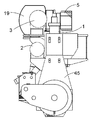
도 1은 일 실시형태에 따른 대형 2-행정 디젤 엔진의 정면도이고,
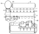
도 2는 도 1의 대형 2-행정 디젤 엔진의 측면도이고,
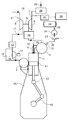
도 3은 도 1에 따른 대형 2-행정 엔진의 개략도이고,
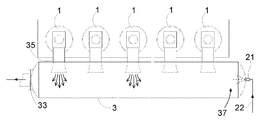
도 4는 도 1의 대형 2-행정 엔진의 실린더 및 배기가스 수용부의 상세도이고, 그리고
도 5 내지 도 7은 그 밖의 실시형태에 따른 대형 2-행정 엔진의 실린더 및 배기가스 수용부의 상세도이다.In the following detailed description of the present description, the invention will be described in more detail with reference to the exemplary embodiments shown in the drawings, in which:
1 is a front view of a large two-stroke diesel engine according to one embodiment,
FIG. 2 is a side view of the large two-stroke diesel engine of FIG. 1;
3 is a schematic representation of a large two-stroke engine according to FIG. 1,
4 is a detailed view of the cylinder and exhaust gas receiving portion of the large two-stroke engine of FIG. 1, and
5 to 7 are detailed views of cylinders and exhaust gas receiving portions of a large two-stroke engine according to another embodiment.
다음의 상세한 설명에서, 대형 2-행정 엔진은 실시형태에 의해 설명될 것이다. 도 1 내지 도 3은 크랭크축(42)과 크로스헤드(43)를 구비한 대형 저속 터보차지 2-행정 디젤 엔진을 도시한다. 도 3은 흡입 및 배기 시스템을 구비한 대형 저속 터보차지 2-행정 디젤 엔진의 개략도를 도시한다. 본 실시형태에서, 상기 엔진은 직렬의 여섯 개의 실린더(1)를 구비한다. 대형 터보차지 2-행정 디젤 엔진은 일반적으로 엔진 프레임(45)에 의해 수용되는 직렬의 다섯 개 내지 열여섯 개의 실린더를 구비한다. 상기 엔진은 예를 들어 해양용 선박에서 주 엔진으로 사용될 수 있거나, 또는 발전소에서 발전기를 작동하기 위한 정치 엔진(stationary engine)으로 사용될 수 있다. 엔진의 총 출력은 예를 들어 5,000 내지 110,000 kW 범위일 수 있다.In the detailed description that follows, a large two-stroke engine will be described by embodiment. 1-3 show a large low speed turbocharged two-stroke diesel engine with a
상기 엔진은 실린더(1)의 하부 영역에서의 소기(scavenge air) 포트와 실린더(1)의 상부에서의 배기 밸브(4)를 구비한 2-행정 단류식이다. 과급 공기는 과급 공기 수용부(2)로부터 각각의 실린더(1)의 소기 포트(미도시)로 통과된다. 실린더(1) 내의 피스톤(41)은 과급 공기를 압축하고, 연료가 분사되고 연소되어 배기가스가 생성된다. 배기 밸브(4)가 개방될 때, 배기가스는 실린더(1)와 관련된 배기 덕트(35)를 통해 배기가스 수용부(3)로 흐르고 SCR 반응기(19)를 포함하는 제 1 배기 도관(18)을 통해 터보차저(5)의 터빈(6)으로 향하며, 이로부터 배기가스는 제 2 배기 도관(7)을 통해 흘러 나간다. 샤프트(8)를 통해 터빈(6)은 공기 유입구(10)를 통해 공급된 에어를 압축하는 컴프레서(9)를 구동시킨다. 상기 컴프레서(9)는 가압된 과급 공기를 과급 공기 도관(11)로 전달하여 과급 공기 수용부(2)로 이어진다.The engine is a two-stroke single flow type with a scavenge air port in the lower region of the
상기 도관(11) 내의 흡기는 컴프레서를 떠난 과급 공기를 대략 200℃에서 36 내지 90℃의 온도로 냉각시키는 인터쿨러(12)를 통과한다.The intake air in the
냉각된 과급 공기는 과급 공기 흐름을 낮은 또는 부분적인 부하 조건으로 압축시키는 전기 모터(17)에 의해 구동되는 보조 송풍기(16)를 통과하여 과급 공기 수용부(2)로 흐른다. 높은 부하에서, 터보차저 컴프레서(9)는 충분한 압축된 소기를 전달하고 이후 보조 송풍기(16)는 체크 밸브(15)를 통해 우회된다.The cooled boost air flows through the
도 3은 SCR 시스템의 레이아웃을 도시한다. 상기 시스템은 배기가스 수용부(3) 외부 그리고 배기가스 수용부(3)의 하류에 있는 선택적 촉매 환원(Selective Catalytic Reduction, SCR) 반응기(19)를 포함한다. 암모니아 또는 요소와 같은 환원제는 상기 SCR 반응기(19)로 진입하기 전에 배기가스에 첨가된다. 배기가스는 상기 SCR 반응기(19)를 통과하기 전에 암모니아 같은 환원제와 혼합되어야 하며, 상기 SCR 반응기(19) 내에서의 화학 반응을 촉진시키기 위해, 온도 수준은 배기가스의 황 함유량에 따라 200 내지 400℃ 사이이어야 한다. 본 실시형태에서, 암모니아의 소스는 수성 요소 용액이다.3 shows a layout of an SCR system. The system comprises a Selective Catalytic Reduction (SCR)
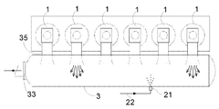
도 3에 도시된 실시형태에서, 탱크(26)는 수성 요소 용액을 수용한다. 도관(25)은 상기 탱크(26)를 펌프(24)의 유입구와 연결한다. 상기 펌프(24)는 실질적으로 일정한 압력을 제공하도록 구성된다. 상기 펌프(24)의 배출구는 가압된 수성 요소 용액을 전자 제어 밸브(23)를 통해 분사 밸브(21)로 전달하는 공급 도관(22)에 연결된다. 본 실시형태에서 상기 전자 제어 밸브(23)는 온/오프 타입이지만, 비례 밸브가 또한 사용될 수 있다. 상기 전자 제어 밸브(23)는 전자 제어 장치(프로세스 컴퓨터, 50)으로부터의 신호에 의해 제어된다. 상기 전자 제어 밸브(23)는 유압식 또는 공압식으로 구동되는 밸브, 또는 순수하게 전자식으로 구동되는 밸브일 수 있다. 상기 분사 밸브(21)는 배기가스 수용부(3) 상에 장착되고, 상기 분사 밸브(21)는 수성 요소 용액이 배기가스 수용부(3) 내로 분사될 때 그것을 분무시키기 위한 노즐 홀을 갖는 노즐을 구비한다. 상기 분사 밸브(21)는 수성 요소 용액을 분무시키기 위한 충분한 압력이 있을 때 분사가 이루어지는 것을 보장하기 위해 압력 임계치가 초과할 때 분사를 개시하도록 구성된다. NOx 및 O2 분석기(32)는 제 2 배기 도관(7)에 연결되고, 분석 결과는 전자 제어 장치(50)로 신호로서 전달된다. 상기 센서(32)는 또한 SCR 반응기(19)의 상류 또는 하류뿐만 아니라 터보차저 터빈(6)의 하류의 도관(18) 내의 배기가스의 NOx 함유량을 측정할 수 있다.In the embodiment shown in FIG. 3, the
배기가스에 분사되는 환원제의 양은 상기 전자 제어 장치(50)에 의해 제어되며, 엔진의 시험대 구동시 측정되는 상이한 구동 조건(부하)에서의 NOx 생성에서 도출된 실제 구동 조건(부하)를 위한 NOx 생성에 근거한다. 배기가스에 분사되는 환원제의 양은 또한 NOx 및 O2 분석기(32)로부터의 신호 또는 경험표(experience table)와 상기 센서(32)로부터의 신호 모두에 근거할 수 있다. 환원제의 분사 타이밍은 엔진의 크랭크축(42)의 실제 위치를 고려하지 않고 이루어질 수 있는데, 이는 분사 지점으로부터 배출구(33)로의 환원제의 경로 상에서 환원제와 배기가스의 혼합을 위해 배기 덕트(35)로부터의 배기가스 제트가 항상 있으므로 필요하지 않기 때문이다.The amount of reducing agent injected into the exhaust gas is controlled by the
이제 도 4를 참조하면, 배기가스 수용부(3)와 환원제 유입 지점의 위치가 실시형태를 통해 더욱 상세하게 설명된다. 배기가스 수용부(3)는 큰 단면적을 갖는 커다랗고 길다란 원통형 수용부이다. Referring now to FIG. 4, the location of the
상기 배기가스 수용부(3)는 상대적으로 근접한 실린더(1)를 따라 배기 밸브(4)와 배기 덕트(35)가 배치된 실린더(1)의 상부 근처에서 연장된다. 배기 덕트(35)는 배기가스 수용부(3)로 이어진다. 많은 엔진에서, 배기가스 수용부(3)는 직렬 엔진의 모든 실린더(1)를 따라 연장된다. 그러나, 상기 배기가스 수용부(3)를 둘 이상의 부분으로 세로로 분리하는 것이 또한 일반적인데, 예를 들어 매우 많은 수의 실린더를 구비한 대형 엔진에 있어서, 배기가스 수용부(3)의 크기가 제조 설비에서 처리할 수 있는 크기를 초과하지 않도록 하기 위한 것이다. 상기 배기가스 수용부(3)를 여러 부분으로 세로로 분리하는 또 다른 이유는 단일 터보차저(5)와 관련된 분할된 배기가스 수용부(3)의 부분을 각각 갖는 다수의 터보차저(5)의 존재일 수 있다.The exhaust
일반적으로, 상기 배기가스 수용부(3)의 단면적은 엔진의 피스톤(41)의 단면적과 동일하거나 크다. 상기 배기가스 수용부(3)의 그에 따른 큰 부피는 실린더(1)와 관련된 배기 밸브(4)가 개방될 때 각각의 실린더(1) 배기 덕트(35)로부터 나오는 배기가스 제트에 의해 형성되는 압력 펄스의 감쇄를 보장한다.In general, the cross-sectional area of the exhaust
상기 배기가스 수용부(3)는 도관(18)과 SCR 반응기(19)를 연결하는 배출구(33)를 구비하고 배기가스 수용부(3)에 포집된 배기가스가 SCR 반응기(19)를 통해 터보차저(5)의 터빈(6)으로 흐르게 한다. 본 실시형태에서, 상기 배출구(33)는 배기가스 수용부(3)의 어느 하나의 종방향 단부에 배치되어 배기가스 수용부(3) 내부의 흐름의 주 방향이 배출구(33)를 향해 일 방향으로 있게 된다.The exhaust
엔진의 실린더(1)는 소정의 점화 순서로 각각 점화한다. 따라서, 배기 밸브(4)는 또한 동일한 순서로 개방되고, 배기 덕트(35)에서 나오는 고속 배기가스 제트(초기에는 100 m/s 이상 나중에 배기 밸브 개방 단계에서는 감소됨)가 동일한 순서로 배기가스 수용부(3)로 진입한다. 6-실린더 2-행정 단류식 디젤 엔진에 있어서, 이는 언제라도 배기가스 수용부(3)로 진입하는 대략 평균 두 개의 배기 제트가 있다는 것을 의미하며, 이는 도 4, 도 6 및 도 7에 도시되어 있다.The
본 실시형태에서 상기 환원제 유입 지점은 분사 밸브(21)이며, 이는 상기 배출구(33) 반대편의 배기가스 수용부의 종방향 단부에 배치된다. 수성 요소 용액은 분무 또는 제트의 형태로 분사 밸브(21)의 노즐 내의 홀로부터 배기가스 수용부(3) 내로 분사된다. 기화된 수성 요소 용액은 배기가스 수용부(3)의 종방향 단부에서 배기가스 수용부(3)로 진입하며, 여기에서 가스 흐름은 비교적 잔잔하고 상기 환원제 유입 지점 근처에서 높은 환원제 농도를 형성한다. 이 잔잔한 영역으로부터 기화된 수성 요소 용액이 배기가스 수용부(3) 내의 흐름의 주 방향으로 배출구(33)로 이송되고 그 과정에서 배기가스로 희석된다. 상기 배기가스 수용부(3) 내의 배기가스의 높은 온도는 요소가 암모니아 가스로 가수분해(열 분해)되게 하며, 분사된 수성 요소 용액의 물 부분은 증발할 것이다. 상기 배출구(33)로의 경로에서, 기화된 수성 요소 용액 및/또는 암모니아와 수증기는 배기 덕트(35)로부터 나오는 하나 이상의 배기가스 제트와 만날 것이다. 고속 배기가스 제트는 배기 가스와 기화된 요소 용액 및/또는 암모니아의 집중적인 혼합을 유발한다. 따라서, 배기가스와 환원제가 배출구(33)에 도달하는 시간까지, 이들은 철저하게 혼합된다. 따라서, 환원제와 배기가스를 혼합하는데 필요한 에너지는 배기가스 제트로부터 나온다. 배기가스 제트 내의 에너지는 어떻게는 주로 큰 부피의 배기가스 수용부(3) 내에서 소실되어, 환원제와 배기가스의 혼합은 터보차지(5)의 터빈(6)으로 향하는 배기가스 스트림 내의 에너지를 손실하지 않고 이루어질 수 있다.The reducing agent inlet point in this embodiment is the
본 실시형태에서, 상기 분사 밸브(21)는 배출구(33) 맞은편의 배기가스 수용부의 가장 먼 단부에 배치된 것으로 도시되어 있다. 그러나, 기타 실시형태와 관련해서 또한 도시되는 바와 같이, 배기가스 수용부(3)의 가장 먼 단부에서의 환원제 분사 지점에 배치할 필요는 없다. 환원제 분사 지점은 환원제가 배출구(33)로 가는 도중에 적어도 하나의 배기가스 제트를 만나는 것이 보장되는 한 배출구(33)에 근접해서 배치될 수 있다.In this embodiment, the
환원제(수성 요소 용액)는 간헐적으로 분사될 수 있는데, 그 이유는 분사된 환원제가 배기가스 수용부(3)에서 배기가스와 혼합되고 균등하게 분포될 수 있는 충분한 시간과 기회가 있기 때문이다. 따라서, 환원제 분사의 타이밍은 중요하지 않다. 이는 전자 제어 밸브(23)의 작동 시간을 제어하는 전자 제어 장치(50)에 의해 본 실시형태에서 타이임에 근거하는 투여량 주입 시스템의 사용을 가능하게 한다. 따라서, 다양한 전달 속도에 걸쳐 타이밍 제어가 정확한 과정이기 때문에, 비교적 간단하고, 정확하며 신뢰할 수 있는 주입 시스템이 제공된다. 단일 환원제 유입 지점이 충분하다는 사실은 또한 시스템을 단순화한다. 환원제 주입이 이러한 타이밍에 의해 제어된다는 사실은 분사를 위해 실질적으로 일정한 압력을 유지시킬 수 있고 따라서 환원제가 각각의 분사에서 적절하게 분무화되는 것을 보장할 수 있는 시스템을 용이하게 제공한다. 환원제 분사의 타이임은 엔진 사이클과는 독립적이데, 즉 분사된 환원제가 배출구(33)로 가는 도중에 항상 배기가스 제트와 만날 것이기 때문에 제트가 존재하는지 존재하지 않는지를 기다릴 필요가 없다. 그런, 환원제 분사의 타이밍은 엔진 사이클과 동조해서 이루어질 수 있으며, 이는 배기가스 수용부(3) 내부에서 분사를 일시적인 유동장(flow field)과 맞출 수 있는 장점이 있다. 따라서, 분사는 국부적인 가스 흐름 속도가 비교적 낮을 때 수행될 수 있다.The reducing agent (aqueous urea solution) may be intermittently sprayed because there is sufficient time and opportunity for the injected reducing agent to be mixed and evenly distributed with the exhaust gas in the exhaust
그 대신에, 환원제 주입 시스템은 분사 압력을 조절함으로써 및/또는 다수의 노즐 중 일정 수의 노즐을 선택적으로 작동시킴으로써 수행되는 제어에 의해 계속되는 스트림을 갖고 작동될 수 있다.Instead, the reducing agent injection system can be operated with a stream that continues by adjusting the injection pressure and / or by control performed by selectively operating a certain number of nozzles among the plurality of nozzles.
환원제와 적절하게 혼합된 배기가스는 배출구(33)로부터 SCR 반응기(19)의 유입구로 흐른다. 이 과정에서, NOx는 N2와 물로 환원된다. SCR 반응기(19)의 유입구로부터, 감소된 양의 NOx를 갖는 배기가스는 터보차저(5)의 터빈(6)으로 흐르며, 이후 제 2 배기 도관(7)로 흐른다. 상기 제 2 도관(7)은 배기가스를 터빈(6)의 배출구로부터 소음기(silencer, 28)로 안내한다. 제 3 배기 도관(29)는 배기가스를 상기 소음기(28)로부터 대기로 안내한다.Exhaust gas suitably mixed with the reducing agent flows from the
도 5는 또 다른 실시형태를 도시한다. 본 실시형태는 도 4의 실시형태와 본질적으로 동일하다. 그러나, 본 실시형태에서, 상기 배출구(33)는 배기가스 수용부(3)의 길이의 대략 중간에 배치된다. 따라서, 배기가스 수용부(3) 내부에 배기가스 수용부(3)의 각각의 종방향 단부에서 배기가스 수용부(3)의 중간의 배출구(33)를 향하는, 흐름의 두 개의 반대하는 주 방향이 있다. 두 개의 환원제 유입 지점이 있으며, 각각은 배기가스 수용부(3)의 마주하는 종방향 단부 각각에 있다. 이들 두 개의 환원제 유입 지점은 두 개의 분사 밸브(21)에 의해 형성된다. 상기 두 개의 분사 밸브(21)는 단일 전제 제어 밸브(23)에 연결되어, 상기 두 개의 분사 밸브(21)는 동시에 분사한다.5 shows another embodiment. This embodiment is essentially the same as the embodiment of FIG. 4. However, in this embodiment, the said
배기가스 수용부(3)의 각각의 종방향 단부의 분사 밸브(21)에 의해 분사된 환원제는 배출구(33)를 향하는 어느 하나의 주 흐름 방향을 따라 이송된다. 배출구(3)로 가는 도중, 환원제는 어느 하나의 배기 덕트(35)로 나오는 적어도 하나의 배기가스 제트와 만날 것이며 따라서 환원제는 배출구(33)를 통해 배기가스 수용부(3)를 떠나기 전에 배기가스와 적절하게 혼합될 것이다. The reducing agent injected by the
도 6은 도 4의 실시형태와 본질적으로 동일한 또 다른 실시형태를 도시한다. 그러나, 엔진의 본 실시형태는 5-기통 직렬 엔진이며 배기가스 수용부(3)는 배출구(33)이 배치된 종방향 단부의 맞은편의 종방향 단부에서 확장된다. 마지막 또는 제 1 배기 덕트(35)를 지나는 확장부 또는 연장부(37)는 환원제의 유입, 분사 및 분무를 위해 배기가스 수용부(3) 내에 잔잔한 또는 조용한 영역을 제공한다. 상기 조용한 영역(37)은 환원제가 적절하게 분무되고 배기가스 수용부(3)의 내벽과 충돌하지 않도록 하고 고농도의 환원제를 갖는 큰 공간이 분사 지점 근처에 형성되는 것을 보장한다. 그 외에는, 상기 분사 밸브(21)와 환원제 분사 방법은 도 4의 실시형태와 동일하다. 도 4에서, 상기 분사 밸브(21)는 배기가스 수용부(3)의 마지막 단부에 배치되지만, 상기 분사 밸브(21)는 환원제가 조용한 영역(37)으로 분무될 수 있게 하는 어떠한 곳이라도 배치될 수 있다는 것을 이해해야 한다.FIG. 6 shows another embodiment which is essentially the same as the embodiment of FIG. 4. However, this embodiment of the engine is a five-cylinder in-line engine and the
도 7은 또 다른 실시형태를 도시한다. 도 7의 실시형태는 도 4의 실시형태와 본질적으로 동일하지만, 환원제 유입 지점은 배기가스 수용부(3)의 마지막 단부에 배치되지 않는다. 그 대신, 상기 환원제 유입 지점은 제 2 및 제 3 실린더(배출구(33)가 배치된 단부 맞은편의 배기가스 수용부의 단부에서 제 1로 시작할 때) 사이에 있다. 분사 밸브(21)/환원제 유입 지점의 이러한 위치로 인해, 분사된 환원제가 배기가스 수용부(3)의 배출구(33)에 도달하기 전에 통과할 네 개의 실린더의 배기 덕트(35)가 여전히 있으며, 이는 환원제가 배출구(33)에 도달하기 전에 적어도 하나의 배기가스 제트와 "부딪치게" 되는 것을 보장한다. 따라서, 환원제와 배기가스의 적절한 혼합이 보장된다. 7 shows another embodiment. The embodiment of FIG. 7 is essentially the same as the embodiment of FIG. 4, but the reducing agent inlet point is not arranged at the last end of the
기본적으로, 유입된 환원제가 배출구(33)에 도달하기 전에 배기가스와 적절하게 혼합되는 것을 보장하기 위해 유입 지점과 배출구(33) 사이에 적어도 3 개의 배기 덕트(35)가 있을 필요가 있다.Basically, there needs to be at least three
청구범위에서 사용되는 바와 같은 용어 "포함하는"는 다른 구성 요소 또는 단계를 배제하지 않는다. 청구범위에서 사용되는 바와 같은 용어 "하나의"는 복수를 배제하지 않는다. 단일 프로세서 또는 기타 장치는 청구범위에 인용된 몇 가지 수단들의 기능을 수행할 것이다.The term "comprising" as used in the claims does not exclude other components or steps. The term "one" as used in the claims does not exclude a plurality. A single processor or other apparatus will perform the functions of several means recited in the claims.
청구 범위에서 사용된 참조 번호는 범위를 제한하는 것을 해석되어서는 안 된다. Reference numerals used in the claims should not be construed as limiting the scope.
본 발명이 설명의 목적으로 상세하게 설명되었지만, 이러한 세부 사항은 그러한 오로지 그러한 목적을 위해서이며, 본 발명의 범위를 벗어나지 않고 본 기술 분야의 숙련자에 의해 변경될 수 있다는 것을 이해해야 한다. 예를 들어, 배기가스 재순환을 이용하는 대형 2-행정 엔진에서도 또한 실시될 수 있다.Although the present invention has been described in detail for purposes of illustration, it is to be understood that these details are for that purpose only and that they may be modified by those skilled in the art without departing from the scope of the present invention. For example, it can also be practiced in large two-stroke engines using exhaust gas recirculation.
1: 실린더 2: 과급 공기 수용부
3: 배기가스 수용부 4: 배기 밸브
5: 터보차저 6: 터빈
7: 제 2 배기 도관 8: 샤프트
9: 컴프레서 10: 공기 유입구
11: 과급 공기 도관 12: 인터쿨러
15: 체크 밸브 16: 송풍기
17: 전기 모터 18: 제 1 배기 도관
19: SCR 반응기 21: 분사 밸브
22: 공급 도관 23: 전자 제어 밸브
24: 펌프 25: 도관
26: 탱크 28: 소음기
29: 제 3 배기 도관 32: NOx 및 O2 분석기 (센서)
33: 배출구 35: 배기 덕트
37: 연장부 41: 피스톤
42: 크랭크축 43: 크로스헤드
45: 엔진 프레임 50: 전자 제어 장치1: cylinder 2: charging air receiver
3: exhaust gas accommodating part 4: exhaust valve
5: turbocharger 6: turbine
7: second exhaust conduit 8: shaft
9: compressor 10: air inlet
11: supercharged air conduit 12: intercooler
15: check valve 16: blower
17: electric motor 18: first exhaust conduit
19: SCR reactor 21: injection valve
22: supply conduit 23: electronic control valve
24: pump 25: conduit
26: tank 28: silencer
29: third exhaust conduit 32: NOx and O2 analyzer (sensor)
33: outlet 35: exhaust duct
37: extension part 41: piston
42: crankshaft 43: crosshead
45: engine frame 50: electronic control unit
Claims (15)
직렬의 다수의 실린더(1),
배기가스 구동 터빈(6) 및 엔진 실린더(1)에 과급 공기를 공급하는 터빈(6)에 의해 구동되는 컴프레서(9)를 구비한 터보차저(5),
상기 실린더(1)를 따라 연장되고 배기 덕트(35)를 통해 상기 실린더(1)에 연결된 길다란 배기가스 수용부(3), 상기 배기 덕트(35)는 고속 배기 가스 제트를 상기 배기가스 수용부(3)의 중공 내부로 보내도록 구성되며,
상기 배기가스 수용부(3)는 배출구(33)를 구비하고,
상기 배기가스 수용부(3)의 배출구(33)와 연결된 선택적 촉매 환원 반응기(19)의 유입구와 상기 터보차저(5)의 터빈(6)의 유입구와 연결된 선택적 촉매 환원 반응기(19)의 배출구를 구비한, 상기 배기가스 수용부(3) 외부의 선택적 촉매 환원 반응기(19),
환원제 유입 지점에서 배기가스에 첨가되는 환원제의 소스(26)를 포함하고,
상기 환원제 유입 지점은, 각각의 배기 덕트로부터 나오는 고속 배기가스 제트가 환원제와 배기가스와의 효과적인 혼합을 가능하게 하도록 배출구(33)의 상류에서 배기가스 수용부(3) 내에 배치되는 것을 특징으로 하는 엔진.In a uniflow type large turbocharged two-stroke diesel engine with a crosshead 43,
Multiple cylinders (1) in series,
A turbocharger (5) having a compressor (9) driven by an exhaust gas drive turbine (6) and a turbine (6) for supplying boost air to the engine cylinder (1);
An elongated exhaust gas receiver 3 extending along the cylinder 1 and connected to the cylinder 1 through an exhaust duct 35, wherein the exhaust duct 35 receives a high speed exhaust gas jet through the exhaust gas receiver. 3) is configured to send inside the hollow,
The exhaust gas accommodating part 3 has an outlet 33,
The outlet of the selective catalytic reduction reactor 19 connected to the inlet of the selective catalytic reduction reactor 19 connected to the outlet 33 of the exhaust gas accommodating part 3 and the inlet of the turbine 6 of the turbocharger 5 is provided. Equipped with a selective catalytic reduction reactor 19 outside the exhaust gas receiving portion 3,
A source of reducing agent 26 added to the exhaust gas at the reducing agent inlet point,
The reducing agent inlet point is characterized in that the high velocity exhaust gas jet from each exhaust duct is arranged in the exhaust gas receiver 3 upstream of the outlet 33 so as to enable effective mixing of the reducing agent with the exhaust gas. engine.
상기 환원제 유입 지점은 환원제 유입 지점과 배출구(33) 사이의 경로를 따라 배치되는 적어도 세 개의 배기 덕트(35)가 있는 배기가스 수용부(3) 내의 위치에 배치되는 것을 특징으로 하는 엔진.The method of claim 1,
Said reducing agent inlet point is arranged at a position in an exhaust gas receiver (3) with at least three exhaust ducts (35) arranged along the path between the reducing agent inlet point and outlet (33).
상기 배출구(33)는 배기가스 수용부(3)의 하나의 종방향 단부에 위치하고 상기 환원제 유입 지점은 배기가스 수용부(3)의 반대편 종방향 단부에 또는 그 근처에 배치되는 것을 특징으로 하는 엔진.The method of claim 1,
The exhaust port 33 is located at one longitudinal end of the exhaust gas receiver 3 and the reducing agent inlet point is arranged at or near the longitudinal end opposite the exhaust gas receiver 3. .
상기 배출구(33)는 배기가스 수용부(3)의 길이의 대략 중간에 위치하고, 두 개의 환원제 유입 지점이 있으며, 이들 각각의 환원제 유입 지점은 배기가스 수용부(3)의 각각의 종방향 단부에 또는 그 근처에 배치되는 것을 특징으로 하는 엔진.The method of claim 1,
The outlet 33 is located approximately in the middle of the length of the exhaust gas receiver 3, and there are two reducing agent inlet points, each of which at each longitudinal end of the exhaust gas receiver 3. Or disposed near the engine.
상기 배기가스 수용부는 환원제를 분사하고 분무하기 위한 조용한 영역을 제공하기 위해 마지막 또는 제 1 배기 덕트(35)를 지나는 연장부(37)를 구비하는 것을 특징으로 하는 엔진.The method according to claim 3 or 4,
The exhaust gas receiver is characterized in that it has an extension (37) through the last or first exhaust duct (35) to provide a quiet area for injecting and spraying the reducing agent.
상기 방법은 상기 배출구(33)의 상류 위치에서 배기가스 수용부(3) 내로 환원제를 분무로서 분사하여 분사된 환원제가 배기가스 수용부의 배출구(33)를 향하는 도중에 만나는 여러 개의 배기가스 제트에 의해 혼합되도록 하여 환원제와 배기가스의 효과적인 혼합을 위해 배기가스 제트의 고속 흐름을 이용하는 단계 및 배기가스와 혼합된 환원제가 상기 배기가스 수용부(3)의 배출구(33)로부터 상기 배기가스 수용부(3) 외부의 SCR 반응기(19)의 유입구로 흐르도록 하는 단계를 포함하는 것을 특징으로 하는 방법.In a method of introducing a reducing agent into an exhaust stream in a single-flow large turbocharged two-stroke multi-cylinder diesel engine with a crosshead 43, the cylinders 1 each have an exhaust duct 35. Is connected to a long diameter exhaust gas receiver 3, the exhaust gas receiver 3 has an outlet 33, and the engine is external to the exhaust gas receiver 3 and a turbocharger ( An SCR reactor 19 disposed upstream of the turbine 6 of 5) and in an exhaust gas stream downstream of the exhaust gas receiver 3;
The method mixes by a plurality of exhaust gas jets where the injected reducing agent meets the way toward the outlet 33 of the exhaust gas receiver by spraying the reducing agent as a spray into the exhaust gas receiver 3 at an upstream position of the outlet 33. Using a high velocity flow of the exhaust gas jet for effective mixing of the reducing agent and the exhaust gas and reducing agent mixed with the exhaust gas from the outlet 33 of the exhaust gas accommodating part 3 to the exhaust gas accommodating part 3. Flowing to an inlet of an external SCR reactor (19).
상기 환원제는 배기가스 수용부(3) 내의 단일 지점에서 유입되거나, 또는 상기 환원제는 배기가스 수용부(3) 내의 종방향으로 마주 보고 배치된 두 개의 환원제 유입 지점에서 유입되는 것을 특징으로 하는 방법.The method according to claim 6,
The reducing agent is introduced at a single point in the exhaust gas receiver (3), or the reducing agent is introduced at two reducing agent inlet points arranged in the longitudinal direction in the exhaust gas receiver (3).
길다란 대직경의 배기가스 수용부(3),
상기 배기가스 수용부(3)의 하류의 배기가스 스트림 내의 그리고 배기가스 수용부(3) 외부의 SCR 반응기(19),
상기 SCR 반응기(19)의 하류의 배기가스 스트림에 환원제를 유입시키기 위한 환원제 유입 지점,
가압 환원제의 소스(24,25,26)를 포함하는 환원제 전달 시스템,
전자 제어 장치(50),
상기 환원제 유입 지점으로의 환원제의 흐름을 제어하기 위한 온/오프 타입의 전자 제어 밸브(23)를 포함하며, 상기 전자 제어 밸브(23)는 상기 전자 제어 장치(50)로부터의 신호에 의해 제어되며,
상기 전자 제어 장치(50)는 상기 전자 제어 밸브(23)의 개방 시간을 제어함으로써 배기가스 스트림에 유입되는 환원제의 양을 제어하도록 구성되는 것을 특징으로 하는 엔진.In a single-flow large turbocharged two-stroke diesel engine with a crosshead,
A large diameter exhaust gas accommodating part 3,
SCR reactor 19 in the exhaust stream downstream of the exhaust gas receiver 3 and outside the exhaust gas receiver 3,
A reducing agent inlet point for introducing a reducing agent into an exhaust stream downstream of the SCR reactor 19,
A reducing agent delivery system comprising a source of pressure reducing agent 24, 25, 26,
Electronic controller 50,
An on / off type electronic control valve 23 for controlling the flow of reducing agent to the reducing agent inlet point, the electronic control valve 23 being controlled by a signal from the electronic control device 50 ,
The electronic control device (50) is configured to control the amount of reducing agent entering the exhaust stream by controlling the opening time of the electronic control valve (23).
상기 전자 제어 장치(5)는 엔진의 실제 작동 조건에서 필요한 환원제의 양에 근거해서 그리고 엔진의 크랭크축(42)의 실제 위치를 고려하지 않고 환원제 유입 지점으로 전달되는 환원제의 양에 대해 상기 전자 제어 밸브(23)의 개방 타이밍을 결정하도록 구성되는 것을 특징으로 하는 엔진.The method of claim 8,
The electronic control device 5 controls the amount of reducing agent delivered to the reducing agent inlet point based on the amount of reducing agent required at the actual operating conditions of the engine and without considering the actual position of the crankshaft 42 of the engine. An engine configured to determine an opening timing of the valve (23).
상기 전자 제어 장치(50)는 배기가스의 NOx 및/또는 O2 함유량에 대한 정보를 근거로 환원제 유입 지점으로 전달되는 환원제의 양을 결정하도록 더 구성되는 것을 특징으로 하는 엔진.The method of claim 9,
The electronic control device (50) is further configured to determine the amount of reducing agent delivered to the reducing agent inlet point based on the information on the NOx and / or O2 content of the exhaust gas.
상기 환원제 유입 지점은 환원제가 배기가스 스트림으로 분사될 때 환원제를 분무하기 위한 노즐을 구비한 분사 밸브(21)에 의해 형성되는 것을 특징으로 하는 엔진.The method of claim 8,
The reducing agent inlet point is formed by an injection valve (21) having a nozzle for spraying the reducing agent when the reducing agent is injected into the exhaust stream.
상기 환원제 유입 지점은 배기가스 수용부(3)의 배출구(33)의 상류에 있는 것을 특징으로 하는 엔진.The method of claim 8,
The reducing agent inlet point is characterized in that it is upstream of the outlet (33) of the exhaust gas receiver (3).
오직 하나 또는 두 개의 환원제 유입 지점이 있는 것을 특징으로 하는 엔진.The method of claim 8,
An engine characterized by having only one or two reducing agent inlet points.
오직 하나의 전자 제어 밸브(23)가 있는 것을 특징으로 하는 엔진.The method of claim 8,
An engine characterized in that there is only one electronically controlled valve (23).
상기 방법은 상기 분사 위치에서 배기가스 수용부(3) 내로 환원제를 분무로서 분사하는 단계 및 상기 전자 제어 밸브(23)의 개방 시간을 제어함으로써 배기가스 스트림에 유입되는 환원제의 양을 제어하여 환원제 유입 지점으로의 환원제의 간헐적인 전달을 유발하는 단계를 포함하는 것을 특징으로 하는 방법.
A method of introducing a reducing agent into an exhaust gas stream in a single-flow large turbocharged two-stroke multi-cylinder diesel engine with a crosshead (43), the engine comprising a long, large diameter exhaust gas receiver (3), the exhaust Reducing agent delivery system comprising an SCR reactor 19, a source of pressurized reducing agent 24, 25 in the exhaust stream downstream of the gas receiver 3 and outside of the exhaust gas receiver 3, electronic control. Apparatus 50 and an on / off type electronic control valve 23 for controlling the flow of the reducing agent upstream of the SCR reactor 19 to the reducing agent inlet point, wherein the electronic control valve 23 is Controlled by a signal from the electronic control device 50,
The method comprises injecting a reducing agent into the exhaust gas receiving portion 3 as a spray at the injection position and controlling the amount of reducing agent entering the exhaust gas stream by controlling the opening time of the electronic control valve 23 to reduce the inlet flow. Causing intermittent delivery of the reducing agent to the point.
Applications Claiming Priority (2)
| Application Number | Priority Date | Filing Date | Title |
|---|---|---|---|
| DKPA201100954 | 2011-12-08 | ||
| DKPA201100954 | 2011-12-08 |
Related Child Applications (1)
| Application Number | Title | Priority Date | Filing Date |
|---|---|---|---|
| KR1020150042392A Division KR20150050536A (en) | 2011-12-08 | 2015-03-26 | A large turbocharged two-stroke diesel engine with exhaust gas purification |
Publications (1)
| Publication Number | Publication Date |
|---|---|
| KR20130064707A true KR20130064707A (en) | 2013-06-18 |
Family
ID=48585028
Family Applications (3)
| Application Number | Title | Priority Date | Filing Date |
|---|---|---|---|
| KR1020120141676A KR20130064707A (en) | 2011-12-08 | 2012-12-07 | A large turbocharged two-stroke diesel engine with exhaust gas purification |
| KR1020150042392A KR20150050536A (en) | 2011-12-08 | 2015-03-26 | A large turbocharged two-stroke diesel engine with exhaust gas purification |
| KR1020160063832A KR101671271B1 (en) | 2011-12-08 | 2016-05-25 | A large turbocharged two-stroke diesel engine with exhaust gas purification |
Family Applications After (2)
| Application Number | Title | Priority Date | Filing Date |
|---|---|---|---|
| KR1020150042392A KR20150050536A (en) | 2011-12-08 | 2015-03-26 | A large turbocharged two-stroke diesel engine with exhaust gas purification |
| KR1020160063832A KR101671271B1 (en) | 2011-12-08 | 2016-05-25 | A large turbocharged two-stroke diesel engine with exhaust gas purification |
Country Status (3)
| Country | Link |
|---|---|
| JP (2) | JP5878860B2 (en) |
| KR (3) | KR20130064707A (en) |
| CN (1) | CN103161548B (en) |
Families Citing this family (12)
| Publication number | Priority date | Publication date | Assignee | Title |
|---|---|---|---|---|
| DK177855B1 (en) * | 2013-09-26 | 2014-09-29 | Man Diesel & Turbo Deutschland | A large low-speed turbocharged two-stroke internal combustion engine with a dual fuel supply system |
| JP6713745B2 (en) * | 2014-10-07 | 2020-06-24 | ヴィンタートゥール ガス アンド ディーゼル アーゲー | Reciprocating internal combustion engines, especially two-stroke large diesel engines, and mixing channels, especially mixing lines |
| DK178941B1 (en) * | 2015-11-09 | 2017-06-19 | Man Diesel & Turbo Filial Af Man Diesel & Turbo Se Tyskland | Large two-stroke engine having a valve arrangement |
| DE102016205299A1 (en) * | 2016-03-31 | 2017-10-05 | Man Diesel & Turbo Se | Internal combustion engine with exhaust aftertreatment system |
| JP6719356B2 (en) * | 2016-10-13 | 2020-07-08 | 川崎重工業株式会社 | Gas engine system |
| EP3351760A1 (en) * | 2017-01-18 | 2018-07-25 | Winterthur Gas & Diesel Ltd. | Propulsion system, method for reducing nox, ship comprising a propulsion system and control system for controlling the injection of a reducing agent |
| CN108180065A (en) * | 2017-12-31 | 2018-06-19 | 徐芝香 | A kind of pressurized exhaust gas pipe |
| JP2019152175A (en) | 2018-03-06 | 2019-09-12 | 日立造船株式会社 | Exhaust emission control device |
| EP3591181A1 (en) * | 2018-07-03 | 2020-01-08 | Winterthur Gas & Diesel Ltd. | Internal combustion engine and method of measuring a component of exhaust in an exhaust gas |
| CN111075520A (en) | 2018-10-18 | 2020-04-28 | 福特全球技术公司 | Internal combustion engine with an exhaust gas aftertreatment system requiring a reducing agent and method for enriching an exhaust gas with a reducing agent |
| EP3670878A1 (en) * | 2018-12-19 | 2020-06-24 | Winterthur Gas & Diesel Ltd. | Internal combustion engine |
| JP2021156250A (en) | 2020-03-30 | 2021-10-07 | 日立造船株式会社 | Exhaust gas desulfurization device |
Family Cites Families (28)
| Publication number | Priority date | Publication date | Assignee | Title |
|---|---|---|---|---|
| JPS6165013A (en) * | 1984-09-06 | 1986-04-03 | Mitsubishi Heavy Ind Ltd | Two-cycle diesel engine |
| JPS62726U (en) * | 1985-06-20 | 1987-01-06 | ||
| JPH0658058B2 (en) * | 1990-03-13 | 1994-08-03 | ダイハツデイーゼル株式会社 | Diesel engine |
| JPH06117222A (en) * | 1992-10-06 | 1994-04-26 | Mitsubishi Heavy Ind Ltd | Denitration device for diesel engine exhaust emission |
| JPH06235319A (en) * | 1993-02-05 | 1994-08-23 | Yanmar Diesel Engine Co Ltd | Internal combustion engine equipped with reduced type denitration catalyst |
| DK199801295A (en) * | 1998-10-12 | 2000-04-13 | Man B & W Diesel Gmbh | Combustion engine with a reactor for reducing NO x content in the exhaust gas and a method |
| US6701707B1 (en) * | 2002-09-04 | 2004-03-09 | Ford Global Technologies, Llc | Exhaust emission diagnostics |
| JP2004263661A (en) * | 2003-03-04 | 2004-09-24 | Toyota Industries Corp | Exhaust emission cleaning device of internal combustion engine |
| DE202005001257U1 (en) * | 2004-09-17 | 2005-04-07 | Arvinmeritor Emissions Tech | Exhaust system of a motor vehicle with diesel engine |
| JP2007056769A (en) * | 2005-08-24 | 2007-03-08 | Daihatsu Motor Co Ltd | Exhaust emission control device |
| US7527134B2 (en) * | 2006-04-03 | 2009-05-05 | Warner Electric Technology Llc | Rotational coupling device |
| DE602006017128D1 (en) * | 2006-04-12 | 2010-11-04 | Man B & W Diesel As | Large two-stroke crosshead diesel engine with DC flush |
| JP4462579B2 (en) | 2006-04-28 | 2010-05-12 | エムエーエヌ・ディーゼル・フィリアル・アフ・エムエーエヌ・ディーゼル・エスイー・ティスクランド | Main bearing support for large two-cycle diesel engines |
| JP4662887B2 (en) * | 2006-05-26 | 2011-03-30 | ボッシュ株式会社 | Exhaust gas purification device for internal combustion engine |
| JP2009103069A (en) * | 2007-10-24 | 2009-05-14 | Denso Corp | Tank device and exhaust emission control system |
| JP5258085B2 (en) * | 2008-02-08 | 2013-08-07 | ボッシュ株式会社 | NOX sensor rationality diagnostic device, rationality diagnostic method, and exhaust purification device for internal combustion engine |
| KR101210870B1 (en) * | 2008-11-11 | 2012-12-11 | 맨 디젤 앤드 터보 필리얼 아프 맨 디젤 앤드 터보 에스이 티스크랜드 | Large two-stroke diesel engine with electronically controlled exhaust valve actuation system |
| JP2011012563A (en) * | 2009-06-30 | 2011-01-20 | Toyota Industries Corp | Exhaust gas purification system |
| JP5503277B2 (en) * | 2009-12-15 | 2014-05-28 | ボッシュ株式会社 | Control device for reducing agent injection valve |
| JP2011127471A (en) * | 2009-12-16 | 2011-06-30 | Mitsubishi Heavy Ind Ltd | Exhaust emission control method and exhaust emission control system for reciprocating internal combustion engine |
| CN101749087B (en) * | 2010-01-07 | 2012-01-25 | 同济大学 | Ammonia selective catalytic reduction method for diesel injected by assistance of compressed natural gas |
| JP5296735B2 (en) * | 2010-03-30 | 2013-09-25 | 三井造船株式会社 | Ships equipped with NOx reduction devices |
| JP5582854B2 (en) * | 2010-04-13 | 2014-09-03 | 日立造船株式会社 | Exhaust gas purification device |
| DK177631B1 (en) * | 2010-05-10 | 2014-01-06 | Man Diesel & Turbo Deutschland | Large two-stroke diesel engine with exhaust gas purification system |
| JP2011236105A (en) * | 2010-05-13 | 2011-11-24 | Toyota Industries Corp | Ammonia release unit, method for releasing ammonia and exhaust gas cleanup unit |
| JP5625475B2 (en) * | 2010-05-17 | 2014-11-19 | いすゞ自動車株式会社 | Exhaust gas purification system |
| SE535773C2 (en) * | 2010-08-13 | 2012-12-11 | Scania Cv Ab | Arrangement for injecting a reducing agent into an exhaust line of an internal combustion engine |
| CN102852604A (en) * | 2012-09-29 | 2013-01-02 | 江苏绿源环保科技有限公司 | Urea injection device for tail gas denitration selective catalytic reduction (SCR) system of marine high-power diesel engine |
-
2012
- 2012-11-28 JP JP2012259439A patent/JP5878860B2/en active Active
- 2012-12-07 KR KR1020120141676A patent/KR20130064707A/en active Application Filing
- 2012-12-07 CN CN201210526510.3A patent/CN103161548B/en active Active
-
2015
- 2015-03-26 KR KR1020150042392A patent/KR20150050536A/en not_active Application Discontinuation
-
2016
- 2016-02-02 JP JP2016017578A patent/JP6276789B2/en active Active
- 2016-05-25 KR KR1020160063832A patent/KR101671271B1/en active IP Right Grant
Also Published As
| Publication number | Publication date |
|---|---|
| KR20160072074A (en) | 2016-06-22 |
| JP5878860B2 (en) | 2016-03-08 |
| JP2016138558A (en) | 2016-08-04 |
| JP6276789B2 (en) | 2018-02-07 |
| KR101671271B1 (en) | 2016-11-01 |
| JP2013122243A (en) | 2013-06-20 |
| KR20150050536A (en) | 2015-05-08 |
| CN103161548A (en) | 2013-06-19 |
| CN103161548B (en) | 2015-06-10 |
Similar Documents
| Publication | Publication Date | Title |
|---|---|---|
| KR101671271B1 (en) | A large turbocharged two-stroke diesel engine with exhaust gas purification | |
| KR101316080B1 (en) | A large turbocharged two-stroke diesel engine with exhaust gas purification | |
| KR101787333B1 (en) | Exhaust system and method for selective catalytic reduction | |
| US8250857B2 (en) | Exhaust aftertreatment system | |
| US20110041495A1 (en) | Systems and methods for exhaust gas recirculation | |
| CN102966469A (en) | Egr venturi diesel injection | |
| CN102695855A (en) | Exhaust gas purification method and exhaust gas purification system for reciprocating internal combustion engine | |
| EP2673484B1 (en) | Exhaust gas receiver, internal combustion engine and method for selective catalytic reduction | |
| CN104005817A (en) | Internal combustion engine | |
| KR101897708B1 (en) | A two-stroke internal combustion engine with a scr reactor located downstream of the exhaust gas receiver | |
| KR101783595B1 (en) | Exhaust system and method for selective catalytic reduction | |
| KR20000028953A (en) | AN INTERNAL COMBUSTION ENGINE HAVING A REACTOR FOR REDUCTION OF THE NOχ CONTENT IN THE EXHAUST GAS, AND A METHOD | |
| WO2013035199A1 (en) | Exhaust gas purifying apparatus | |
| KR20180005601A (en) | Exhaust-gas after treatment system and internal combustion engine | |
| WO2014068172A1 (en) | Method for mixing reducing agent with exhaust gas and exhaust system | |
| WO2014188056A1 (en) | Exhaust system | |
| JPH01227810A (en) | Internal combustion engine |
Legal Events
| Date | Code | Title | Description |
|---|---|---|---|
| A201 | Request for examination | ||
| E902 | Notification of reason for refusal | ||
| AMND | Amendment | ||
| E601 | Decision to refuse application | ||
| AMND | Amendment | ||
| E902 | Notification of reason for refusal | ||
| AMND | Amendment | ||
| A107 | Divisional application of patent | ||
| J201 | Request for trial against refusal decision | ||
| J301 | Trial decision |
Free format text: TRIAL DECISION FOR APPEAL AGAINST DECISION TO DECLINE REFUSAL REQUESTED 20150326 Effective date: 20160425 |