KR20130044623A - Steel-concrete composite beam for reducing story height and flatplate structure and construction method thereof - Google Patents
Steel-concrete composite beam for reducing story height and flatplate structure and construction method thereof Download PDFInfo
- Publication number
- KR20130044623A KR20130044623A KR1020110108773A KR20110108773A KR20130044623A KR 20130044623 A KR20130044623 A KR 20130044623A KR 1020110108773 A KR1020110108773 A KR 1020110108773A KR 20110108773 A KR20110108773 A KR 20110108773A KR 20130044623 A KR20130044623 A KR 20130044623A
- Authority
- KR
- South Korea
- Prior art keywords
- web
- composite beam
- steel
- concrete
- strand
- Prior art date
Links
Images

Classifications
-
- E—FIXED CONSTRUCTIONS
- E04—BUILDING
- E04C—STRUCTURAL ELEMENTS; BUILDING MATERIALS
- E04C3/00—Structural elongated elements designed for load-supporting
- E04C3/02—Joists; Girders, trusses, or trusslike structures, e.g. prefabricated; Lintels; Transoms; Braces
- E04C3/29—Joists; Girders, trusses, or trusslike structures, e.g. prefabricated; Lintels; Transoms; Braces built-up from parts of different material, i.e. composite structures
- E04C3/293—Joists; Girders, trusses, or trusslike structures, e.g. prefabricated; Lintels; Transoms; Braces built-up from parts of different material, i.e. composite structures the materials being steel and concrete
-
- E—FIXED CONSTRUCTIONS
- E01—CONSTRUCTION OF ROADS, RAILWAYS, OR BRIDGES
- E01D—CONSTRUCTION OF BRIDGES, ELEVATED ROADWAYS OR VIADUCTS; ASSEMBLY OF BRIDGES
- E01D2/00—Bridges characterised by the cross-section of their bearing spanning structure
-
- E—FIXED CONSTRUCTIONS
- E04—BUILDING
- E04B—GENERAL BUILDING CONSTRUCTIONS; WALLS, e.g. PARTITIONS; ROOFS; FLOORS; CEILINGS; INSULATION OR OTHER PROTECTION OF BUILDINGS
- E04B5/00—Floors; Floor construction with regard to insulation; Connections specially adapted therefor
- E04B5/43—Floor structures of extraordinary design; Features relating to the elastic stability; Floor structures specially designed for resting on columns only, e.g. mushroom floors
-
- E—FIXED CONSTRUCTIONS
- E04—BUILDING
- E04C—STRUCTURAL ELEMENTS; BUILDING MATERIALS
- E04C3/00—Structural elongated elements designed for load-supporting
- E04C3/02—Joists; Girders, trusses, or trusslike structures, e.g. prefabricated; Lintels; Transoms; Braces
- E04C3/04—Joists; Girders, trusses, or trusslike structures, e.g. prefabricated; Lintels; Transoms; Braces of metal
- E04C3/10—Joists; Girders, trusses, or trusslike structures, e.g. prefabricated; Lintels; Transoms; Braces of metal prestressed
Landscapes
- Engineering & Computer Science (AREA)
- Architecture (AREA)
- Civil Engineering (AREA)
- Structural Engineering (AREA)
- Physics & Mathematics (AREA)
- Electromagnetism (AREA)
- Chemical & Material Sciences (AREA)
- Composite Materials (AREA)
- Rod-Shaped Construction Members (AREA)
Abstract
Description
본 발명은 강합성보 및 이를 구비한 바닥판 구조 및 바닥판 구조 시공방법에 관한 것이며, 더욱 상세하게는 보의 두께를 줄이고 무내화피복을 실현하여 층고를 절감하는 강합성보 및 이를 구비한 바닥판 구조 및 바닥판 구조 시공방법에 관한 것이다.The present invention relates to a steel composite beam and a bottom plate structure and a method for constructing a bottom plate structure, and more particularly, a steel composite beam and a bottom plate structure having the same by reducing the thickness of the beam and realizing a fire-resistant coating. And a bottom plate structure construction method.
철근콘크리트 보는 경제적인 구조이지만 휨모멘트를 받게 되면 균열이 발생하기 때문에 보의 춤이 커지는 단점과 함께 장스팬 구조물에 적용하기 어려운 한계가 있다. 이러한 철근콘크리트 보의 약점을 보완하는 것으로 프리스트레스 콘크리트보가 있다. Reinforced concrete beam is an economical structure, but it is difficult to apply to long-span structure with the disadvantage that the dance of the beam increases because the crack occurs when the bending moment is received. Complementing the weakness of these reinforced concrete beams is prestressed concrete beams.
이러한 프리스트레스 콘크리트 보는 프리스트레스 도입방법에 따라 프리텐션 방식과 포스트텐션 방식으로 구분할 수 있다.The prestressed concrete beams can be classified into pretension and posttension methods according to the prestress introduction method.
프리텐션 방식은 강연선에 인장력을 주어 긴장해 놓은 채 콘크리트를 치고, 콘크리트가 경화된 후에 강연선의 인장력을 서서히 풀어서 콘크리트에 프리스트레스를 주는 방법으로, 콘크리트와 강연선의 부착에 의해 프리스트레스를 도입하는 방식이다. 즉, 프리텐션 방식은 인장대(Stressing bed)등 제작설비를 이용하여 강연선을 긴장하고 콘크리트가 타설/양생된 후 강연선을 끊어서 콘크리트에 프리스트레스를 도입한다. 이러한 프리텐션 방식은 복잡한 제작설비를 필요로 하기 때문에 현장시공에 적합하지 않고 주로 공장제작형 PC부재에 적용된다. The pretension method is a method of striking concrete while giving tension to a stranded wire and then pre-stressing the concrete by releasing the tensile force of the stranded wire gradually after the concrete is cured. In other words, the pretension method uses prefabrication equipment such as a stressing bed to strain the strand, and after the concrete is poured / cured, break the strand and introduce prestress into the concrete. This pretension method is not suitable for field construction because it requires complicated manufacturing equipment, and is mainly applied to factory-made PC members.
포스트텐션 방식은 콘크리트가 경화한 후에 강연선을 긴장하여 그 끝을 콘크리트에 정착함으로써 프리스트레스를 도입하는 방법으로, 단부에 정착된 지압판에 의해 프리스트레스를 도입하는 방식이다. 즉, 포스트텐션 방식은 미리 콘크리트 내부에 쉬스관을 묻어 두고 그 사이에 강연선을 배치한 후 콘크리트를 타설 경화하고 단부에 설치된 정착판과 긴장장비를 이용하여 프리스트레스를 도입한다. 이러한 포스트텐션 방식은 주로 현장시공 방식으로 적용된다.The post tension method is a method in which prestress is introduced by tensioning a stranded wire and fixing the end to concrete after the concrete is cured. The post tension method is a method of introducing prestress by a pressure plate fixed at an end. In other words, the post-tension method is to bury the sheath pipe in the concrete in advance, place the strand between them, then pour the concrete and prestress is introduced by using the fixing plate and tension equipment installed at the end. This post tension method is mainly applied in the field construction method.
그러나 상기한 종래의 프리스트레스 콘크리트 보는 다음과 같은 단점이 있다.However, the conventional prestressed concrete beam described above has the following disadvantages.
첫째, 프리텐션 방식은 부재제작을 위해 인장대(stressing bed)등 대형 플랜트 설비가 필요하고, 특히 프리스트레스 효과를 극대화하기 위한 강연선 배치를 위해 별도의 강연선 절곡장치(tendon hold-down device)가 필요하며, 이에 따라 제작비용이 증가한다.First, the pretension method requires a large plant facility such as a stressing bed to manufacture the member, and in particular, a separate hold hold-down device is required for arranging the strand to maximize the prestress effect. As a result, manufacturing costs increase.
둘째, 프리텐션 방식은 PC로 제작되기 때문에 중량이 무거워 대형장비를 이용하여 운반, 조립하여야 하는 등 현장작업에 어려움이 있고, 또한 접합부 처리가 불확실하여 구조적인 안전성을 담보하기 어렵다.Second, since the pretension method is made of PC, the weight is heavy, so it is difficult to carry out on-site work such as transporting and assembling using large equipment, and it is difficult to secure structural safety due to uncertainty of joint processing.
셋째, 종래 포스트텐션 방식을 이용하더라도 쉬스관 매입, 정착판 설치 등 작업량이 많고, 여전히 보의 휨강도 증가와 처짐량 감소를 위하여 보의 춤의 두께가 바닥판보다 두껍게 되어 층고가 높아질 수 있다. 또한, 별도의 내화피복 또한 요구되어 자재비용 및 시공량이 증가하는 문제가 있다.Third, even when using the conventional post-tension method, the work load such as sheath pipe embedding, fixing plate installation is still large, and the thickness of the dance of the beam is thicker than the bottom plate to increase the bending strength of the beam and reduce the amount of deflection. In addition, a separate fireproof coating is also required to increase the material cost and construction amount.
본 발명은 상기와 같은 종래 문제점을 해소하기 위하여 제안된 것으로서 그 목적 측면은, 프리스트레스를 도입하여 내력이 증대화됨으로써 층고를 절감하여 공간활용이 극대화시키는 층고절감형 강합성보 및 이를 구비한 바닥판 구조 및 바닥판 구조 시공방법를 제공하는 데에 있다.The present invention has been proposed in order to solve the conventional problems as described above, the object of the present invention is to reduce the height by introducing a prestress to increase the strength to reduce the height of the floor height-saving steel composite beam and the bottom plate structure having the same And to provide a method for constructing the bottom plate structure.
또한 본 발명은 일 측면으로써, 하부인장이 보강됨으로써 휨강도가 증대되며 처짐성능이 향상되고, 이러한 구조적 보강으로 무내화 피복이 가능한 층고절감형 강합성보 및 이를 구비한 바닥판 구조 및 바닥판 구조 시공방법를 제공하는 것을 목적으로 한다. In another aspect, the present invention, as the lower tension is reinforced, the flexural strength is increased and the deflection performance is improved, and the structural reinforcement of the low-strength steel composite beam and the bottom plate structure and the bottom plate structure construction method that can be fire-resistant coating by such structural reinforcement It aims to provide.
상기와 같은 목적을 달성하기 위한 기술적인 측면으로서 본 발명은, 상부 플랜지와, 상기 상부 플랜지와 평행하게 배치되는 하부플랜지 및, 상기 상부플랜지와 상기 하부플랜지 사이에 배치되는 웨브를 구비하며, 상기 웨브의 양측에 콘크리트부가 일체로 타설되는 보부재;와, 상기 웨브 양측에 상기 웨브의 길이방향으로 배치되어 상기 콘크리트부에 긴장력을 제공하는 적어도 하나의 강연선;과, 상기 웨브 양측에 배치되어 상기 웨브 및 상기 상부 플랜지 및 하부플랜지와 3면이 접합되며, 상기 강연선이 통과하는 제1슬롯이 형성된 적어도 하나의 스티프너;를 포함하는 층고절감형 강합성보를 제공한다.As a technical aspect for achieving the above object, the present invention comprises an upper flange, a lower flange disposed in parallel with the upper flange, and a web disposed between the upper flange and the lower flange, the web Beam members are integrally cast on both sides of the beam member, and at least one of the strands disposed in the longitudinal direction of the web on both sides of the web to provide a tension force to the concrete portion; and the web is disposed on both sides of the web and The upper flange and the lower flange and the three sides are bonded, at least one stiffener formed with a first slot through which the strand passes; provides a high-strength reduction-type composite beam comprising a.
바람직하게는, 상기 보부재의 휨강도를 증대시키도록 상기 웨브의 양측에 상기 보부재의 길이방향으로 설치되는 보강철근;을 더 포함할 수 있다.Preferably, the reinforcing bars are installed in the longitudinal direction of the beam member on both sides of the web to increase the bending strength of the beam member; may further include.
또한 바람직하게는, 상기 제1슬롯은 수직방향으로 길게 형성될 수 있다.Also preferably, the first slot may be formed long in the vertical direction.
바람직하게는, 상기 스티프너는 중앙 아래에 형성된 제2슬롯을 포함하며, 상기 보강철근은 상기 제2슬롯을 관통하여 위치가 고정되도록 설치되는 것을 특징으로 하는 층고절감형 강합성보를 제공할 수 있다.Preferably, the stiffener may include a second slot formed below the center, the reinforcing bar can be provided through the second slot to provide a layer-reduced high-strength composite beam characterized in that the position is fixed.
더욱 바람직하게는, 상기 보강철근은 정착력을 증대시키도록 양단부 중 적어도 어느 하나의 단부에 절곡하여 형성된 절곡부를 구비할 수 있다.More preferably, the reinforcing bar may be provided with a bent portion formed by bending at least one end of both ends to increase the fixing force.
바람직하게는, 상기 보부재는, H형강으로 제공되며, 상기 하부플랜지 상면에 데크플레이트가 설치되기 용이하도록 상기 하부플랜지가 상기 상부플랜지보다 길게 형성되는 비대칭 철골보로 제공될 수 있다.Preferably, the beam member is provided as an H-shaped steel, the lower flange may be provided as an asymmetric cheolgolbo is formed longer than the upper flange so that the deck plate is easily installed on the upper surface.
한편 바람직하게는, 상기 강연선을 소정 위치에 고정시키도록 웨브의 양측에 구비되는 위치고정부재;를 더 포함할 수 있다.
On the other hand, preferably, a position fixing member which is provided on both sides of the web to fix the strand in a predetermined position; may further include.
한편, 다른 측면으로서 본 발명은, 강합성보;와, 상기 강합성보의 상기 하부플랜지에 안착되는 데크플레이트;와, 상기 데크플레이트의 상부면에 형성되며, 상기 강연선 및 스티프너가 매립되도록 타설되는 콘크리트부;를 포함하는 강합성보를 이용한 바닥판 구조를 제공한다. On the other hand, the present invention as another aspect, the steel composite beam; and the deck plate seated on the lower flange of the steel composite beam; and the concrete portion formed on the upper surface of the deck plate, the steel wire and the stiffener is poured to be embedded It provides a bottom plate structure using a steel composite beam comprising a.
바람직하게는, 상기 보부재는 상기 하부플랜지 상면에 데크플레이트가 설치되기 용이하도록 상기 하부플랜지가 상기 상부플랜지보다 길게 형성되는 비대칭 철골보로 제공될 수 있다.
Preferably, the beam member may be provided as an asymmetrical cheolgolbo is formed in the lower flange longer than the upper flange so that the deck plate is easy to be installed on the upper surface of the lower flange.
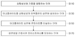
한편, 또 다른 측면으로서 본 발명은, 강합성보와 기둥을 접합하는 단계;와, 데크플레이트를 상기 강합성 보에 구비된 하부플랜지 상면에 설치하는 단계;와, 상기 데크플레이트 상면에 상기 강연선이 매립되도록 콘크리트를 타설하는 단계; 와, 상기 강연선을 긴장시켜 프리스트레스를 도입하는 단계;를 포함하는 바닥판 구조 시공방법을 제공한다.On the other hand, the present invention as another aspect, the step of bonding the steel composite beam and the pillar; And, installing the deck plate on the upper surface of the lower flange provided on the composite beam; And, the strand wire is embedded in the deck plate upper surface Pouring concrete if possible; And a step of introducing the prestress by tensioning the stranded wire.
바람직하게는, 상기 콘크리트를 타설하는 단계 전에, 상기 보부재의 휨강도를 증대하도록 상기 웨브의 양측에 상기 스티프너를 관통하여 보강철근을 배근하는 단계;를 더 포함할 수 있다.Preferably, before the step of placing the concrete, the step of reinforcing the reinforcing bars through the stiffeners on both sides of the web to increase the flexural strength of the beam member.
이와 같은 본 발명의 일실시예에 따른 층고절감형 강합성보에 의하면, 형강과 프리스트레스 콘크리트의 합성작용으로 내력이 증대화된 강합성보를 제공할 수있다. 이에 따라, 장스팬이 가능하여 중간기둥을 생략할 수 있고, 보의 춤을 줄일 수 있어 층고를 절감할 수 있으므로, 건물의 공간활용 극대화시킬 수 있는 효과를 얻을 수 있다.According to the layer-reduced steel composite beam according to an embodiment of the present invention as described above, it is possible to provide a steel composite beam with increased strength by the composite action of the section steel and prestressed concrete. Accordingly, the long span can be omitted, the middle pillar can be omitted, and the dance of the beam can be reduced, so that the floor height can be reduced, thereby maximizing the space utilization of the building.
또한, 본 발명의 일실시예에 의하면, 바닥에 인접하게 설치된 보강철근에 의해 강합성보의 휨성능이 보강되며 처짐성능이 향상될 수 있고, 이러한 구조적 보강으로 무내화 피복을 가능하게 하는 효과를 얻을 수 있다.In addition, according to one embodiment of the present invention, the bending performance of the steel composite beam is reinforced by the reinforcing bars installed adjacent to the floor and the deflection performance can be improved, and this structural reinforcement can achieve the effect of enabling fire-resistant coating. Can be.
아울러, 본 발명의 실시예에 의하면, 포스트텐션 방식을 이용하므로 현장에서 프리스트레스를 도입할 수 있고, 강합성보에 타설되는 콘크리트를 현장에서 타설할 수 있으므로 합성보의 중량을 줄이면서 운반 및 설치작업을 용이하게 할 수 있다. 또한, 별도의 인장대 등의 장치 없이 강연선을 모멘트분포곡선에 대응하는 형태로 배치할 수 있어 현장작업을 용이하게 하는 효과를 얻을 수 있다.In addition, according to the embodiment of the present invention, since the post-tension method can be used to introduce the prestress in the field, and can be cast in the field of concrete to be placed in the steel composite beam in the field, easy transport and installation work while reducing the weight of the composite beam. It can be done. In addition, the strand can be arranged in a form corresponding to the moment distribution curve without a separate tensioning device, such as to facilitate the field work.
그리고, 본 발명의 실시예에 의하면, 바닥판 구조에 데크플레이트를 이용함으로서 무거푸집 시공이 가능해져 공사기간을 단축시킬 수 있다.In addition, according to the embodiment of the present invention, by using the deck plate in the bottom plate structure it is possible to form a heavy construction can shorten the construction period.
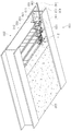
도 1은 본 발명의 일실시예에 따른 강합성보를 이용한 바닥판 구조를 나타내는 사시도이다.
도 2는 본 발명의 일실시예에 따른 강합성보를 나타내는 단면도이다.
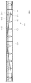
도 3은 본 발명의 일실시예에 따른 강합성보를 나타내는 측면도이다.
도 4는 본 발명의 일실시예에 따른 강합성보를 나타내는 사시도이다.
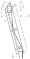
도 5는 본 발명의 일실시예에 따른 강합성보와 데크플레이트의 결합관계를 나타내는 사시도이다.
도 6는 본 발명에 따른 바닥판 구조 시공방법을 나타내는 플로우차트이다.1 is a perspective view showing a bottom plate structure using a steel composite beam according to an embodiment of the present invention.
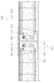
2 is a cross-sectional view showing a steel composite beam according to an embodiment of the present invention.
3 is a side view showing a steel composite beam according to an embodiment of the present invention.
Figure 4 is a perspective view showing a steel composite beam according to an embodiment of the present invention.
5 is a perspective view showing a coupling relationship between the steel composite beam and the deck plate according to an embodiment of the present invention.
6 is a flowchart illustrating a method of constructing a bottom plate structure according to the present invention.
이하, 첨부된 도면에 따라 본 발명을 상세하게 설명한다.Hereinafter, the present invention will be described in detail with reference to the accompanying drawings.
먼저, 이하에서 설명되는 실시예들은 본 발명인 층고절감형 강합성보 및 이를 구비한 바닥판 구조 및 바닥판 구조 시공방법의 기술적인 특징을 이해시키기에 적합한 실시예들이다. 다만, 본 발명이 이하에서 설명되는 실시예에 한정하여 적용되거나 설명되는 실시예들에 의하여 본 발명의 기술적 특징이 제한되는 것이 아니며, 본 발명의 기술 범위 내에서 다양한 변형 실시가 가능하다.
First, the embodiments to be described below are embodiments suitable for understanding the technical features of the present invention, the layered high-strength rigid composite beam and the bottom plate structure and the bottom plate structure construction method having the same. However, the technical features of the present invention are not limited by the embodiments to which the present invention is applied or explained in the following embodiments, and various modifications are possible within the technical scope of the present invention.
도 1 내지 도 5는 본 발명의 일실시예에 따른 층고절감형 강합성보(100)를 도시한다. 본 발명은 H형강을 이용한 철근 콘크리트 보에 긴장재인 강연선(130)을 이용하여 프리스트레스를 도입하는 것을 기초로 한다. 긴장재를 이용하여 프리스트레스를 도입하는 방법에는 프리텐션 방식과 포스트텐션 방식이 있는데, 본 발명은 콘크리트가 경화된 후에 상기 강연선(130)을 긴장하여 그 끝을 콘크리트에 정착함으로써 프리스트레스를 도입하는 포스트텐션 방식을 이용한다.1 to 5 illustrate a layer height-reduced rigid
본 발명의 일실시예에 의한 층고절감형 강합성보(100)는, 도 1 내지 도 5에 도시된 일실시예와 같이, 보부재(110)와, 강연선(130)과, 스티프너(150)를 포함하여 구성될 수 있다. The high-strength layered steel
상기 보부재(110)는, 상부 플랜지(111)와, 상기 상부 플랜지(111)와 평행하게 배치되는 하부 플랜지(112) 및, 상기 상부 플랜지(111)와 상기 하부 플랜지(112) 사이에 배치되는 웨브(113)를 구비하며, 상기 웨브(113)의 양측에 콘크리트부(230)가 일체로 타설될 수 있다. The
즉, 상기 보부재(110)는 상, 하로 평행하게 배치되는 상, 하부 플랜지(111,112)와 상기 상, 하부 플랜지(111,112) 사이에 수직하게 배치되는 웨브(113)로 구성된 H형강으로 제공될 수 있다. 그리고, 상기 웨브(113)의 양측은 상기 보부재(110)에 연결되는 바닥판에 타설되는 콘크리트부(230)로 채워질 수 있다.That is, the
한편, 상기 강연선(130)은 상기 웨브(113) 양측에 상기 웨브(113)의 길이방향으로 배치되어 상기 콘크리트부(230)에 긴장력을 제공할 수 있다. On the other hand, the
즉, 상기 강연선(130)은 콘크리트부(230)에 상기 보부재(110)의 축방향으로 압축력을 도입함으로써, 상기 보부재(110)가 휨모멘트를 받을 때 균열이 발생하지 않도록 하고, 보부재(110)의 처짐을 최소화할 수 있다. That is, the
이때, 상기 강연선(130)을 이용하여 철근 콘크리트 보로 제공되는 상기 보부재(110)에 프리스트레스를 도입하는 방법에는 프리텐션 방식과 포스트텐션 방식이 있으나, 프리텐션 방식은 복잡한 제작설비를 필요로 하므로, 현장시공에 적합한 포스트텐션 방식을 이용하는 것이 바람직하다.At this time, there is a pretension method and a post-tension method for introducing prestress to the
본 발명은 상술한 바와 같이, 포스트텐션 방식을 이용하므로 상기 콘크리트부(230)가 타설되고 경화된 후에 상기 강연선(130)을 긴장시켜 그 끝단부를 콘크리트부(230)에 정착시켜 지압판 등을 이용하여 프리스트레스를 도입하게 된다.As described above, since the post-tension method is used, the
한편, 상기 스티프너(150)는, 상기 웨브(113) 양측에 배치되어 상기 웨브(113) 및 상기 상부 플랜지(111) 및 하부 플랜지(112)와 3면이 접합될 수 있고, 상기 강연선(130)이 통과하는 제1슬롯(151)을 구비하며 적어도 하나로 제공될 수 있다. On the other hand, the
즉, 상기 스티프너(150)는 도 5에 도시된 바와 같이, 상기 보부재(110)의 축 방향에 대하여 수직방향으로 설치되며, 바람직하게는 상기 보부재(110)의 길이방향으로 이격되게 복수 개가 설치될 수 있다. That is, the
또한, 상기 스티프너(150)는 상기 제1슬롯(151)이 형성되어 상기 보부재(110)의 웨브(113) 양측에 배치되는 상기 강연선(130)이 통과할 수 있다. 이에 따라, 상기 스티프너(150)는 상기 보부재(110)의 플랜지나 웨브(113)의 좌굴을 방지함과 동시에, 후술하는 바와 같이, 상기 제1슬롯(151)을 통하여 상기 강연선(130)의 위치를 고정하기 용이하게 하여 프리스트레스를 도입하기 위한 제작비용을 절감하고 시공과정을 간단하게 하는 역할을 할 수 있다. 또한, 상기 스티프너(150)는 상기 보부재(110)와 연결되는 상기 바닥판에 의한 하중을 지지하는 역할을 할 수 있다.In addition, the
한편, 상기 제1슬롯(151)은, 도 2에 도시된 바와 같이, 수직방향으로 길게 형성될 수 있다. On the other hand, the
이에 따라, 상기 복수 개의 스티프터 각각의 설치위치에 따라 상기 강연선(130)이 적정한 높이에 배치될 수 있다. 이때, 상기 제1슬롯(151)에는 후술하는 바와 같이 위치고정부재(133)가 접합되어 상기 강연선(130)을 모멘트 곡선에 대응되는 형태로 배치할 수 있다.Accordingly, the
한편, 본 발명에 의한 층고절감형 강합성보(100)는, 상기 보부재(110)의 휨강도를 증대시키도록 상기 웨브(113)의 양측에 상기 보부재(110)의 길이방향으로 설치되는 보강철근(170)을 더 포함할 수 있다. On the other hand, the high-strength layered
이때, 상기 스티프너(150)는 중앙 아래에 형성된 제2슬롯(153)을 포함할 수 있고, 상기 보강철근(170)은 상기 제2슬롯(153)을 관통하여 위치가 고정되도록 설치될 수 있다. In this case, the
즉, 상기 보강철근(170)은 도 2 내지 도 5에 도시된 바와 같이, 상기 스티프너(150)에서 상기 하부 플랜지(112)에 인접하게 설치된 상기 제2슬롯(153)을 관통하여 설치됨으로써 상기 하부 플랜지(112)에 인접하게 설치될 수 있다. 이때, 상기 제2슬롯(153)은 하부플랜지로부터 예를 들어, 40mm정도 떨어져 형성될 수 있다. That is, the reinforcing
이에 따라, 상기 보강철근(170)이 상기 보부재(110)의 하부에 위치하여 하부 인장재로서의 역할을 함으로써, 상기 보부재(110)의 휨성능이 보강되며 처짐성능도 향상될 수 있다. 따라서, 상기 보강철근(170)을 구비함으로써 상기 보부재(110)의 춤을 바닥판 두께 정도로 줄일 수 있다. Accordingly, since the reinforcing
또한, 상기 보강철근(170)은, 화재시 상기 하부플랜지가 노출되어 강도가 저하되어도 상기 하부플랜지를 대신하여 휨 등에 저항할 수 있으므로, 상기 하부플랜지에 별도의 내화피복을 필요로 하지 않는 이점이 있다. In addition, the reinforcing
따라서, 상기 보강철근(170)은 상기 보부재(110)의 춤을 줄일 수 있게 하여 건물의 층고를 절감함으로써 공간활용도가 높아지게 할 수 있고, 상기 하부플랜지의 무내화피복을 가능하게 하는 효과를 얻을 수 있다. Therefore, the reinforcing
다만, 도 2 및 도 5에는 상기 제2슬롯(153)은 상기 보강철근(170)의 형상에 따라 원형홀인 경우를 도시하고 있으나, 이에 한정되는 것은 아니며, 상기 보강철근(170)을 관통배치하고 위치를 고정시킬 수 있다면 다양한 변형실시가 가능하다. 또한, 상기 보강철근에 의해 상기 하부플랜지의 무내화 피복이 가능하지만, 상기 하부플랜지의 내화 피복을 배제하는 것은 아니다. 2 and 5 illustrate the case where the
이때, 상기 보강철근(170)은 정착력을 증대시키도록 양단부 중 적어도 어느 하나의 단부에 절곡하여 형성된 절곡부(173)를 구비할 수 있다.In this case, the reinforcing
즉, 도 1 및 도 5에 도시된 바와 같이, 상기 보강철근(170)의 양단부 혹은 어느 한 단부를 절곡하여 보의 양측에 배치할 수 있고, 이에 따라, 상기 보강철근(170)은 상기 콘크리트부(230)에 매립된 후 정착력이 향상될 수 있다. That is, as shown in Figures 1 and 5, both ends or one end of the reinforcing
한편, 상기 보부재(110)는, H형강으로 제공되며, 상기 하부 플랜지(112) 상면에 데크플레이트(210)가 설치되기 용이하도록 상기 하부 플랜지(112)가 상기 상부 플랜지(111)보다 길게 형성되는 비대칭 철골보로 제공될 수 있다.On the other hand, the
즉, H형강으로 제공되는 상기 보부재(110)는 슬라브를 구성하는 바닥판과의 연결시 상기 바닥판의 하부에 구비된 데크플레이트(210)가 상기 하부 플랜지(112)에 안착될 수 있는데, 이와 같이 상기 하부 플랜지(112)의 안착이 용이하도록 상기 하부 플랜지(112)가 상기 상부 플랜지(111)보다 길게 형성될 수 있다. That is, the
한편, 본 발명의 일실시예에 의한 층고절감형 강합성보(100)는, 상기 강연선(130)을 소정 위치에 고정시키도록 웨브(113)의 양측에 구비되는 위치고정부재(133)를 더 포함하여 구성될 수 있다. On the other hand, the layer-reduced
이때, 상기 위치고정부재(133)는 예를 들어 철근 등으로 구성될 수 있으며, 상기 스티프너(150)에 수직방향으로 형성된 상기 제1슬롯(151)의 적정한 위치에 연결 접합되어 상기 강연선(130)의 위치를 고정시킬 수 있다. 또한, 후술하는 바와 같이, 상기 바닥판의 데크플레이트(210) 상부에 설치되는 철근(211)에 고정설치될 수도 있다. At this time, the
이에 따라, 상기 강연선(130)은 도 3에 도시된 실시예와 같이, 현장에서 상기 스티프너(150)의 제1슬롯(151)을 관통하여 사하중에 의한 모멘트 분포도에 대응하는 형태, 예를 들어 포물선 또는 Harped shape 형태로 웨브(113) 양쪽에 설치될 수 있다.Accordingly, the
다만, 상기 위치고정부재(133)의 연결방법은 이에 한정되지 않으며 상기 강연선(130)의 위치를 고정할 수 있도록 상기 웨브(113)의 양측에 배치된다면 다양한 변형실시가 가능하다.
However, the method of connecting the
한편, 이하에서는 본 발명의 또 다른 측면인 강합성보(100)를 이용한 바닥판 구조(200)에 대하여 설명한다. On the other hand, it will be described below the
상기 바닥판 구조(200)는, 상기 강합성보(100)와 상기 강합성보(100)의 하부 플랜지(112)에 안착되는 데크플레이트(210)와, 상기 데크플레이트(210)의 상부면에 형성되며 상기 강연선(130) 및 스티프너(150)가 매립되도록 타설되는 콘크리트부(230)를 포함하여 구성될 수 있다.The
즉, 본 발명에 의한 바닥판 구조(200)는 데크플레이트(210)를 이용하여 건물의 슬라브 바닥구조를 이루는 것을 기초로 한다. 이때, 상기 데크플레이트(210)는 철근 콘크리트 구조물에서 거푸집 역할을 하면서 동시에 건축물의 바닥면 지지구조물을 이루는 금속판에 철근(211)을 일체로 부착한 건축자재이다. 이때, 상기 철근(211)은 도 5에 도시된 실시예와 같이, 예를 들어 금속판과 평행하게 배치되는 상부철근과 하부철근 및 이에 고정설치되는 레티스 철근으로 구성할 수 있다. 다만, 상기 철근은 이에 한정되는 것은 아니다.That is, the
상기 바닥판 구조(200)는 이러한 데크플레이트(210)가 상기 보부재(110)의 하부 플랜지(112)에 안착되어 바닥판과 상기 강합성보(100)의 연결을 용이하게 하는 효과를 얻을 수 있다. 이때, 상기 데크플레이트(210)는 용접 또는 볼트결합으로 상기 하부 플랜지(112)에 장착되어 고정될 수 있다.The
또한, 상기 데크플레이트(210)의 상면에는 상기 철근이 매립되도록 콘크리트가 타설되는 콘크리트부(230)가 형성될 수 있으며, 이때, 상기 콘크리트부(230)는 상기 강연선(130)과 상기 스티프너(150)가 매립되도록 타설될 수 있다. 이에 따라 상기 보부재(110)는 철근 콘크리트 강합성보(100)로 구성될 수 있다.In addition, the upper surface of the
한편, 상기 보부재(110)는 상기 하부 플랜지(112) 상면에 데크플레이트(210)가 설치되기 용이하도록 상기 하부 플랜지(112)가 상기 상부 플랜지(111)보다 길게 형성되는 비대칭 철골보로 구성될 수 있다. On the other hand, the
즉, 상술한 바와 같이 상기 보부재(110)가 비대칭 철골보로 구성됨으로써 상기 데크플레이트(210)를 상기 보부재(110)에 설치하기 용이해지므로, 시공성이 향상될 수 있다.
That is, as described above, since the
한편, 이하에서는 도 1 내지 도 5를 참조하여 본 발명의 또 다른 측면인 바닥판 구조 시공방법에 대하여 설명한다. 다만, 상술한 구성과 동일한 구성에 대한 자세한 설명은 생략한다.On the other hand, with reference to Figures 1 to 5 will be described for the bottom plate structure construction method which is another aspect of the present invention. However, detailed description of the same configuration as the above-described configuration will be omitted.
본 발명의 일실시예에 의한 바닥판 구조 시공방법은, 강합성보(100)와 기둥을 접합하는 단계(S110)와, 데크플레이트(210)를 상기 강합성보에 구비된 하부 플랜지(112) 상면에 설치하는 단계(S130)와, 상기 데크플레이트(210) 상면에 상기 강연선(130)이 매립되도록 콘크리트를 타설하는 단계(S150)와, 상기 강연선(130)을 긴장시켜 프리스트레스를 도입하는 단계(S170)를 포함하여 구성될 수 있다. The construction method of the bottom plate structure according to an embodiment of the present invention, the step (S110) for joining the
이때, 상기 강합성보(100)는 상술한 바와 같이 구성된 보부재(110)와 강연선(130)과, 스티프너(150)를 포함하여 구성될 수 있다. At this time, the
상기 강합성보(100)와 기둥(미도시)을 접합하는 단계(S110)는, 상술한 바와 같이 구성된 강합성보(100)를 상기 기둥에 접합할 수 있지만, 상기 보부재(110)를 상기 기둥에 접합한 후에 상기 강연선(130)을 설치할 수도 있다. In the step S110 of joining the
또한, 상기 데크플레이트(210)를 상기 하부플랜지(112)에 설치하는 단계(S130)는, 상기 데크플레이트(210)를 용접 또는 볼트결합으로 상기 하부 플랜지(112)에 장착하여 고정시킬 수 있다.In addition, in the step S130 of installing the
상기 프리스트레스를 도입하는 단계(S170)는, 상기 콘크리트가 타설된 후 경화된 다음 상기 강연선(130)을 긴장시켜 상기 콘크리트부(230)에 압축력을 가하게 된다. 즉, 본 발명의 일실시예에 따른 바닥판구조의 시공방법에 의하면 상기 강합성보(100)에 프리스트레스를 도입하는 방법으로 포스트텐션 방식을 이용할 수 있다.In the step (S170) of introducing the prestress, the concrete is hardened after being poured and then the compressive force is applied to the
따라서, 본 발명에 의한 바닥판 구조 시공방법에 의하면, 현장시공성이 향상되고, 공사기간이 단축될 수 있으며 프리스트레스를 도입하기 위한 제작설비 비용이 절감되어 공사비를 절감할 수 있는 효과를 얻을 수 있다. Therefore, according to the construction method of the floor plate structure according to the present invention, the site workability can be improved, the construction period can be shortened, and the cost of manufacturing equipment for introducing prestress can be reduced, thereby reducing the construction cost.
한편, 상기 콘크리트를 타설하는 단계(S150) 전에, 상기 보부재(110)의 휨강도를 증대하도록 상기 웨브(113)의 양측에 상기 스티프너(150)를 관통하여 보강철근(170)을 배근하는 단계를 더 포함할 수 있다.On the other hand, before the step of placing the concrete (S150), the step of reinforcing the reinforcing
즉, 도 2 및 도 5에 도시된 상기 스티프너(150)는 중앙 아래에 형성된 제2슬롯(153)을 포함할 수 있고, 상기 보강철근(170)은 상기 제2슬롯(153)을 관통하여 위치가 고정되도록 설치될 수 있다. 이에 따라, 상기 스티프너(150)는 상기 제2슬롯(153)에 끼워짐으로써 고정설치될 수 있고, 상기 하부 플랜지(112)에 인접하게 배치되어 상기 보부재(110)의 하부 인장재의 역할을 할 수 있다.That is, the
이에 따라, 상기 보부재(110)의 휨 성능이 보강되며 처짐 성능이 향상될 수 있다. 따라서, 상기 강합성보(100)는 상기 보강철근(170)에 의해서 상기 보부재(110)의 춤을 바닥판 두께정도로 줄일 수 있게 하여 건물의 층고를 절감할 수 있는 효과를 얻을 수 있다. Accordingly, the bending performance of the
또한, 상기 보강철근(170)의 단부를 절곡하여 콘크리트부(230)에 매립되도록 절곡부(173)를 형성함으로써 상기 보강철근(170)의 정착력을 향상시킬 수 있다.
In addition, by bending the end of the reinforcing
이와 같은 본 발명의 일실시예에 따른 층고절감형 강합성보를 이용하면, 형강과 프리스트레스 콘크리트의 합성작용으로 내력이 증대화된 강합성보를 제공할 수 있다. 이에 따라, 장스팬이 가능하여 중간기둥을 생략할 수 있고, 보의 춤을 줄일 수 있어 층고를 절감할 수 있으므로, 건물의 공간활용 극대화시킬 수 있는 효과를 얻을 수 있다.By using the layer-reduced steel composite beam according to an embodiment of the present invention as described above, it is possible to provide a steel composite beam having increased strength by the composite action of the section steel and prestressed concrete. Accordingly, the long span can be omitted, the middle pillar can be omitted, and the dance of the beam can be reduced, so that the floor height can be reduced, thereby maximizing the space utilization of the building.
또한, 바닥에 인접하게 설치된 보강철근에 의해 강합성보의 휨성능이 보강되며 처짐성능이 향상될 수 있고, 이러한 구조적 보강으로 무내화 피복이 가능한 강합성보를 제공할 수 있다.
In addition, the flexural performance of the steel composite beam can be reinforced by the reinforcing bars installed adjacent to the floor, and the deflection performance can be improved, and this structural reinforcement can provide a steel composite beam capable of fire-resistant coating.
본 발명은 지금까지 특정한 실시 예에 관련하여 도시하고 설명하였지만, 이하의 특허청구범위에 의해 마련되는 본 발명의 정신이나 분야를 벗어나지 않는 한 도내에서 본 발명이 다양하게 개조 및 변화될 수 있다는 것을 당 업계에서 통상의 지식을 가진 자는 용이하게 알 수 있음을 밝혀두고자 한다. While the invention has been shown and described in connection with specific embodiments so far, it will be appreciated that the invention can be variously modified and varied without departing from the spirit or scope of the invention as set forth in the claims below. It will be appreciated that those skilled in the art can easily know.
100 : 층고절감형 강합성보 110 : 보부재
130 : 강연선 150 : 스티프너
151 : 제1슬롯 153 : 제2슬롯
170 : 보강철근 200 : 바닥판 구조
210 : 데크플레이트 230 : 콘크리트부100: layer high-strength reduction composite beam 110: beam member
130: strand 150: stiffener
151: first slot 153: second slot
170: rebar 200: bottom plate structure
210: deck plate 230: concrete part
Claims (11)
상기 웨브 양측에 상기 웨브의 길이방향으로 배치되어 상기 콘크리트부에 긴장력을 제공하는 적어도 하나의 강연선; 및,
상기 웨브 양측에 배치되어 상기 웨브 및 상기 상부 플랜지 및 하부플랜지와 3면이 접합되며, 상기 강연선이 통과하는 제1슬롯이 형성된 적어도 하나의 스티프너;
를 포함하는 층고절감형 강합성보.
A beam member having an upper flange, a lower flange disposed in parallel with the upper flange, and a web disposed between the upper flange and the lower flange, wherein the beam member is integrally cast on both sides of the web;
At least one strand wire disposed on both sides of the web in the longitudinal direction of the web to provide tension to the concrete part; And
At least one stiffener disposed on both sides of the web and joined to the web, the upper flange, and the lower flange, and having three first slots through which the strand passes;
High-strength stiffness beam comprising a layer.
상기 보부재의 휨강도를 증대시키도록 상기 웨브의 양측에 상기 보부재의 길이방향으로 설치되는 보강철근;을 더 포함하는 것을 특징으로 하는 층고절감형 강합성보.
The method of claim 1,
Reinforced steel beam further comprises; reinforcing bars are installed in the longitudinal direction of the beam member on both sides of the web to increase the bending strength of the beam member.
상기 제1슬롯은 수직방향으로 길게 형성된 것을 특징으로 하는 층고절감형 강합성보.
The method of claim 1,
The first slot is a layer-reduced high strength composite beam, characterized in that formed long in the vertical direction.
상기 스티프너는 중앙 아래에 형성된 제2슬롯을 포함하며,
상기 보강철근은 상기 제2슬롯을 관통하여 위치가 고정되도록 설치되는 것을 특징으로 하는 층고절감형 강합성보.
The method of claim 2,
The stiffener includes a second slot formed below the center,
The reinforced reinforcing bar is characterized in that the reinforcing bar is installed so that the position is fixed through the second slot.
상기 보강철근은 정착력을 증대시키도록 양단부 중 적어도 어느 하나의 단부에 절곡하여 형성된 절곡부를 구비하는 것을 특징으로 하는 층고절감형 강합성보.
The method according to claim 2, wherein
The reinforcing bar is a high-strength layer-reinforced composite beam, characterized in that having a bent portion formed by bending at least one end of both ends to increase the fixing force.
상기 보부재는, H형강으로 제공되며, 상기 하부플랜지 상면에 데크플레이트가 설치되기 용이하도록 상기 하부플랜지가 상기 상부플랜지보다 길게 형성되는 비대칭 철골보로 제공되는 것을 특징으로 하는 층고절감형 강합성보.
The method of claim 1,
The beam member is provided as an H-shaped steel, the lower layer-type steel composite beam, characterized in that the lower flange is provided as an asymmetric cheolgolbo is formed longer than the upper flange so that the deck plate is easy to be installed on the upper surface.
상기 강연선을 소정 위치에 고정시키도록 상기 웨브의 양측에 구비되는 위치고정부재;를 더 포함하는 것을 특징으로 하는 층고절감형 강합성보.
The method of claim 1,
And a position fixing member provided on both sides of the web to fix the strand in a predetermined position.
상기 강합성보의 상기 하부플랜지에 안착되는 데크플레이트;
상기 데크플레이트의 상부면에 형성되며, 상기 강연선 및 스티프너가 매립되도록 타설되는 콘크리트부;
를 포함하는 강합성보를 이용한 바닥판 구조.
A composite synthetic beam of any one of claims 1 to 5;
A deck plate seated on the lower flange of the steel composite beam;
A concrete part formed on an upper surface of the deck plate and being poured to embed the stranded wire and the stiffener;
Bottom plate structure using a steel composite beam comprising a.
상기 보부재는 상기 하부플랜지 상면에 데크플레이트가 설치되기 용이하도록 상기 하부플랜지가 상기 상부플랜지보다 길게 형성되는 비대칭 철골보로 제공되는 것을 특징으로 하는 강합성보를 이용한 바닥판 구조.
9. The method of claim 8,
The beam member is a bottom plate structure using a steel composite beam, characterized in that the lower flange is provided as an asymmetrical cheolgolbo is formed longer than the upper flange so that the deck plate is easily installed on the upper surface.
데크플레이트를 상기 강합성 보에 구비된 하부플랜지 상면에 설치하는 단계;
상기 데크플레이트 상면에 상기 강연선이 매립되도록 콘크리트를 타설하는 단계; 및.
상기 강연선을 긴장시켜 프리스트레스를 도입하는 단계;
를 포함하는 바닥판 구조 시공방법.
Bonding the steel composite beam of any one of claims 1 to 7 and the pillar;
Installing a deck plate on an upper surface of a lower flange provided in the rigid beam;
Placing concrete so that the strand is embedded on the deck plate; And.
Tensioning the strand and introducing prestress;
Bottom plate structure construction method comprising a.
상기 보부재의 휨강도를 증대하도록 상기 웨브의 양측에 상기 스티프너를 관통하여 보강철근을 배근하는 단계;를 더 포함하는 것을 특징으로 하는 바닥판 구조 시공방법.12. The method of claim 11, before the step of pouring the concrete,
And reinforcing reinforcing bars through the stiffeners on both sides of the web to increase the flexural strength of the beam member.
Priority Applications (1)
| Application Number | Priority Date | Filing Date | Title |
|---|---|---|---|
| KR1020110108773A KR101286557B1 (en) | 2011-10-24 | 2011-10-24 | Steel-concrete composite beam for reducing story height and flatplate structure |
Applications Claiming Priority (1)
| Application Number | Priority Date | Filing Date | Title |
|---|---|---|---|
| KR1020110108773A KR101286557B1 (en) | 2011-10-24 | 2011-10-24 | Steel-concrete composite beam for reducing story height and flatplate structure |
Publications (2)
| Publication Number | Publication Date |
|---|---|
| KR20130044623A true KR20130044623A (en) | 2013-05-03 |
| KR101286557B1 KR101286557B1 (en) | 2013-07-22 |
Family
ID=48656983
Family Applications (1)
| Application Number | Title | Priority Date | Filing Date |
|---|---|---|---|
| KR1020110108773A KR101286557B1 (en) | 2011-10-24 | 2011-10-24 | Steel-concrete composite beam for reducing story height and flatplate structure |
Country Status (1)
| Country | Link |
|---|---|
| KR (1) | KR101286557B1 (en) |
Cited By (8)
| Publication number | Priority date | Publication date | Assignee | Title |
|---|---|---|---|---|
| CN104264899A (en) * | 2014-10-17 | 2015-01-07 | 上海天华建筑设计有限公司 | Embedded U-shaped steel-encased concrete combined beam |
| CN106088434A (en) * | 2016-08-25 | 2016-11-09 | 中冶建筑研究总院有限公司 | A kind of assembling type steel structure overlapped hollow floor system and construction method thereof |
| CN106149882A (en) * | 2016-08-25 | 2016-11-23 | 中冶建筑研究总院有限公司 | A kind of lateral resisting and antigravity separate steel structure of housing system and construction method thereof |
| CN109653403A (en) * | 2019-01-15 | 2019-04-19 | 中国五冶集团有限公司 | Column plate concrete combined type shear wall and its construction method |
| CN109849167A (en) * | 2019-02-28 | 2019-06-07 | 北京市政路桥股份有限公司 | A kind of health preserving equipment and method guaranteeing T beam concrete Early-age behavior |
| CN115095080A (en) * | 2022-07-19 | 2022-09-23 | 华神建设集团有限公司 | Construction method of ultrahigh, overweight and large-span cast-in-situ concrete beam |
| KR102577800B1 (en) * | 2022-12-26 | 2023-09-20 | 이숙희 | Reducing height type girder and construction method |
| KR102577799B1 (en) * | 2022-12-13 | 2023-09-20 | 이숙희 | Girder for reducing height type |
Families Citing this family (1)
| Publication number | Priority date | Publication date | Assignee | Title |
|---|---|---|---|---|
| KR101814038B1 (en) * | 2014-11-11 | 2018-01-02 | (주)바로건설기술 | Structure Having Hollowness Slave and Its Construction Method |
Family Cites Families (3)
| Publication number | Priority date | Publication date | Assignee | Title |
|---|---|---|---|---|
| KR20040057127A (en) * | 2002-12-24 | 2004-07-02 | 재단법인 포항산업과학연구원 | A floor structure reduced thickness with using a preflex beam |
| KR100761785B1 (en) * | 2005-06-28 | 2007-09-28 | (주)엠씨에스공법 | Mold-concrete composite crossbeam |
| KR100982974B1 (en) * | 2009-12-21 | 2010-09-17 | (주)아이브릿지코리아 | Method for manufacturing multi-span continuous re-prestressed preflex composite bridge |
-
2011
- 2011-10-24 KR KR1020110108773A patent/KR101286557B1/en active IP Right Grant
Cited By (10)
| Publication number | Priority date | Publication date | Assignee | Title |
|---|---|---|---|---|
| CN104264899A (en) * | 2014-10-17 | 2015-01-07 | 上海天华建筑设计有限公司 | Embedded U-shaped steel-encased concrete combined beam |
| CN104264899B (en) * | 2014-10-17 | 2016-05-11 | 上海天华建筑设计有限公司 | Embedded outsourcing U-shaped steel-concrete composite beam |
| CN106088434A (en) * | 2016-08-25 | 2016-11-09 | 中冶建筑研究总院有限公司 | A kind of assembling type steel structure overlapped hollow floor system and construction method thereof |
| CN106149882A (en) * | 2016-08-25 | 2016-11-23 | 中冶建筑研究总院有限公司 | A kind of lateral resisting and antigravity separate steel structure of housing system and construction method thereof |
| CN109653403A (en) * | 2019-01-15 | 2019-04-19 | 中国五冶集团有限公司 | Column plate concrete combined type shear wall and its construction method |
| CN109849167A (en) * | 2019-02-28 | 2019-06-07 | 北京市政路桥股份有限公司 | A kind of health preserving equipment and method guaranteeing T beam concrete Early-age behavior |
| CN115095080A (en) * | 2022-07-19 | 2022-09-23 | 华神建设集团有限公司 | Construction method of ultrahigh, overweight and large-span cast-in-situ concrete beam |
| CN115095080B (en) * | 2022-07-19 | 2023-11-10 | 华神建设集团有限公司 | Construction method of ultrahigh overweight large-span cast-in-situ concrete beam |
| KR102577799B1 (en) * | 2022-12-13 | 2023-09-20 | 이숙희 | Girder for reducing height type |
| KR102577800B1 (en) * | 2022-12-26 | 2023-09-20 | 이숙희 | Reducing height type girder and construction method |
Also Published As
| Publication number | Publication date |
|---|---|
| KR101286557B1 (en) | 2013-07-22 |
Similar Documents
| Publication | Publication Date | Title |
|---|---|---|
| KR101286557B1 (en) | Steel-concrete composite beam for reducing story height and flatplate structure | |
| KR100797194B1 (en) | Composite concrete column and construction method using the same | |
| KR101136926B1 (en) | Composite beam by prestressed concrete filled tube | |
| KR101222620B1 (en) | Prestressed concrete girder and it's manufacture and construction method which used pretensioning steel plate | |
| WO2011012974A2 (en) | Method for manufacturing a precast composite steel and concrete beam and a precast composite steel and concrete beam made according to said method | |
| JP2017172143A (en) | Junction structure of precast concrete floor slab for rapid construction work, and construction method of the same | |
| KR101045929B1 (en) | Pro-environment prestressed long span light-weight precast concrete panel and this construction technique | |
| KR101913069B1 (en) | Prestressed Steel-Concrete Composite Girder and Method for Fabricating thereof | |
| KR20090068536A (en) | Concrete-composite crossbeam and construction methods of slab structure using the same | |
| KR101084993B1 (en) | Prestress steel composite panel with prestress non-introducing portions provided at both ends and manufacturing method thereof | |
| KR100343960B1 (en) | Steel concrete structure | |
| KR101752285B1 (en) | Hybrid beam with wide PSC lower flange and enlarged section upper flange and structure frame using the same | |
| KR20060022324A (en) | Construction method for prestressed composite slab | |
| KR101181160B1 (en) | Prestressed precast concrete beam having efficient prestressing anchorage structure | |
| KR20100125504A (en) | Prestress concrete composite with prestress non-introducing portion selectively installed at upper and lower portions to which compression force is applied, manufacturing method thereof, slab structure and construction method using the same | |
| KR101151773B1 (en) | Prestress steel composite girder with prestress non-introducing portions respectively provided at both ends thereof and manufacturing method thereof | |
| KR100899713B1 (en) | Bridge structure of steel composite girder using precast arch-deck, and constructing method thereof | |
| KR101819326B1 (en) | Steel-concrete composite girder and construction method | |
| KR101765389B1 (en) | Light weight precast beam with void implementing archi mechanism | |
| KR101087586B1 (en) | Steel concrete composite beam and manufacturing method of the same | |
| KR101387232B1 (en) | Moment framework system | |
| CN215211883U (en) | Pre-tensioned pre-stressed frame assembly structure system | |
| KR20140046111A (en) | Fabrication method for prestressed concrete beam | |
| KR200384109Y1 (en) | Concrete-composite Crossbeam | |
| JP5128569B2 (en) | Prestressed concrete beam |
Legal Events
| Date | Code | Title | Description |
|---|---|---|---|
| A201 | Request for examination | ||
| A302 | Request for accelerated examination | ||
| E902 | Notification of reason for refusal | ||
| E701 | Decision to grant or registration of patent right | ||
| GRNT | Written decision to grant | ||
| FPAY | Annual fee payment |
Payment date: 20160711 Year of fee payment: 4 |
|
| FPAY | Annual fee payment |
Payment date: 20170707 Year of fee payment: 5 |
|
| FPAY | Annual fee payment |
Payment date: 20180710 Year of fee payment: 6 |
|
| FPAY | Annual fee payment |
Payment date: 20190709 Year of fee payment: 7 |