KR20130018264A - Connecting element for a friction weld connection for connecting at least two plate-like components - Google Patents
Connecting element for a friction weld connection for connecting at least two plate-like components Download PDFInfo
- Publication number
- KR20130018264A KR20130018264A KR1020127027244A KR20127027244A KR20130018264A KR 20130018264 A KR20130018264 A KR 20130018264A KR 1020127027244 A KR1020127027244 A KR 1020127027244A KR 20127027244 A KR20127027244 A KR 20127027244A KR 20130018264 A KR20130018264 A KR 20130018264A
- Authority
- KR
- South Korea
- Prior art keywords
- mandrel
- connecting element
- pin
- connection
- centering portion
- Prior art date
Links
Images


Classifications
-
- B—PERFORMING OPERATIONS; TRANSPORTING
- B23—MACHINE TOOLS; METAL-WORKING NOT OTHERWISE PROVIDED FOR
- B23K—SOLDERING OR UNSOLDERING; WELDING; CLADDING OR PLATING BY SOLDERING OR WELDING; CUTTING BY APPLYING HEAT LOCALLY, e.g. FLAME CUTTING; WORKING BY LASER BEAM
- B23K20/00—Non-electric welding by applying impact or other pressure, with or without the application of heat, e.g. cladding or plating
- B23K20/12—Non-electric welding by applying impact or other pressure, with or without the application of heat, e.g. cladding or plating the heat being generated by friction; Friction welding
- B23K20/129—Non-electric welding by applying impact or other pressure, with or without the application of heat, e.g. cladding or plating the heat being generated by friction; Friction welding specially adapted for particular articles or workpieces
-
- Y—GENERAL TAGGING OF NEW TECHNOLOGICAL DEVELOPMENTS; GENERAL TAGGING OF CROSS-SECTIONAL TECHNOLOGIES SPANNING OVER SEVERAL SECTIONS OF THE IPC; TECHNICAL SUBJECTS COVERED BY FORMER USPC CROSS-REFERENCE ART COLLECTIONS [XRACs] AND DIGESTS
- Y10—TECHNICAL SUBJECTS COVERED BY FORMER USPC
- Y10T—TECHNICAL SUBJECTS COVERED BY FORMER US CLASSIFICATION
- Y10T403/00—Joints and connections
- Y10T403/47—Molded joint
- Y10T403/477—Fusion bond, e.g., weld, etc.
Abstract
본 발명은 적어도 두 개의 판형 부품(8, 9)을 연결하기 위한 마찰 용접 연결부용 연결 요소(1)로서, 맨드릴(2)이 상부 부품(들)(8)을 관통함에 따라 회전되고 압력을 받는 연결 요소(1)의 중심을 결정하고 안내하기 위한 센터링부(4)를 가지며, 상기 맨드릴(2)의 길이는 상기 상부 부품(들)(8)의 두께에 부합하도록 구성된, 연결 요소(1)에 관한 것이다. 센터링부는 마찰 용접 연결부로 변화되는 상기 맨드릴(2)의 실질적으로 평평한 횡단 표면(6, 12)으로부터 핀(4, 13, 16, 18)으로서 돌출되고, 상부 부품(들)을 관통한 후에 상기 센터링부의 소재가 연화되어 센터링부가 마찰 용접 연결부로 거의 완전히 변화될 정도로, 맨드릴(2)의 길이에 비해 짧고 얇게 형성된다.The present invention relates to a connection element 1 for a friction welding connection for connecting at least two plate-like parts 8, 9, wherein the mandrel 2 is rotated and pressurized as it passes through the upper part (s) 8. Connection element 1, having a centering portion 4 for determining and guiding the center of the connection element 1, the length of the mandrel 2 being configured to match the thickness of the upper part (s) 8. It is about. The centering protrudes as pins 4, 13, 16, 18 from substantially flat transverse surfaces 6, 12 of the mandrel 2 which is transformed into friction welded connections and after passing through the upper part (s). The material of the part is soft and short and thin compared to the length of the mandrel 2, so that the centering part is almost completely changed to the friction welding connection.
Description
본 발명은, 적어도 두 개의 판형 부품을 연결하기 위한 마찰 용접 연결부용 연결 요소로서, 상부 부품(들)을 상기 상부 부품(들)의 두께에 그 길이가 부합하는 맨드릴로 관통시키는 동안 회전되고 압력을 받는 상기 연결 요소의 중심을 결정하고 안내하는 센터링부(centering part)를 갖는 연결 요소에 관한 것이다.The present invention provides a connection element for a friction welded connection for connecting at least two plate-like parts, the rotating part of which is rotated while the upper part (s) is passed through a mandrel whose length corresponds to the thickness of the upper part (s). A connecting element having a centering part for determining and guiding the center of said receiving element.
마찰 용접 공정은 이미, 예를 들어 미국 특허 제3,477,115호에 개시된 바와 같이, 두 개의 판형 부품을 영구적으로 연결하기 위해 사용되고 있다. 이 특허 공보에서는 연결 요소를 서로의 상부에 놓이는 두 개의 금속 판 위에 배치하고 나서 상부 부품을 관통하여 회전되고 구동되게 하는 방법을 설명하고 있다. 이 공정에서는, 연결 요소의 일부분인 맨드릴 영역에서 발생되는 마찰열로 인해 상부 부품이 맨드릴의 영역에서 용융될 정도로 가열되고 이에 따라 맨드릴이 하부 부품의 영역까지 관통할 수 있게 되며, 상부 부품과 하부 부품의 소재가 다시 고화되고 연결 요소가 회전을 중지하고 나면 맨드릴은 그 상태로 유지된다. 그러면, 상기 연결 요소에 장착된 칼라(collar)가 상기 상부 부품 위에 위치되고, 이에 따라 두 개의 부품은 서로 견고하게 연결된 상태로 유지된다. Friction welding processes are already used to permanently connect two plate-like parts, as disclosed, for example, in US Pat. No. 3,477,115. This patent describes a method of placing a connecting element on two metal plates on top of each other and then rotating and driving through the upper part. In this process, frictional heat generated in the area of the mandrel, which is part of the connecting element, causes the upper part to heat up to melt in the area of the mandrel, thus allowing the mandrel to penetrate into the area of the lower part, After the material solidifies again and the connecting element stops rotating, the mandrel stays in that state. A collar mounted to the connecting element is then placed over the upper part, whereby the two parts remain firmly connected to each other.
또한, 독일 특허 공개 공보 DE 10 2009 006 775 A1호는 두 개의 인접한 피가공물, 즉 실시예에 명시된 것과 같은 두 개의 판금부를 연결하기 위한 연결 요소를 개시한다. 그 특징으로서, 연결 요소 또는 접합 요소는 둥근 맨드릴의 형태로 구성되고 두 피가공물의 접합성을 개선시키기 위한 둥근 돌출부를 구비한다. 그러나, 이 특허 공개 공보에서는 이러한 구성을 선택한 구체적인 이유를 밝히고 있지 않다. In addition,
두 개의 판형 부품을 연결하기 위한 이러한 구성들에 의하면, 연결 요소들이 그들의 맨드릴 영역에서 테이퍼지게 만들어질 수 있고 이에 따라 비교적 뾰족하게 테이퍼진 부분이 중심 결정 기능을 갖게 할 수 있다는 것이 이미 밝혀졌다(독일 특허 공개 공보 DE 10 2006 013 529 A1호 참조). 이는 정교한 제조 공정이 요구되는 비교적 복잡한 구성이다. 따라서, 이는 프레스 기술을 이용한 저비용 대량 생산에는 적당하지 않으며, 명백히 이 이유 때문에 사용되지 않고 있다. These arrangements for joining two plate parts have already shown that the connecting elements can be tapered in their mandrel areas, thus allowing a relatively sharp tapered part to have a central decision function (Germany See
본 발명의 목적은, 적은 제조 노력으로 생산될 수 있고, 또한 이어지는 후속 공정에서, 연속 작업으로 적어도 두 개의 판형 부품의 마찰 용접 연결부를 얻는 데에 사용될 수 있도록 상기 적어도 두 개의 판형 부품을 연결하기에 특히 적절한 연결 요소를 제공하는 데 있다. 본 발명의 연결 요소의 구성은 한편으로는 마찰 용접 연결부에 대한 정확한 안내를 보장하고 다른 한편으로는 두 판의 튼튼한 연결을 보장한다.The object of the present invention is to connect the at least two plate parts so that they can be produced with less manufacturing effort and can also be used in subsequent subsequent processes to obtain a friction weld connection of at least two plate parts in a continuous operation. In particular, to provide a suitable connection element. The construction of the connection element of the present invention ensures on the one hand the correct guidance to the friction welded connection and on the other hand ensures a robust connection of the two plates.
본 발명의 연결 요소는, 센터링부가 마찰 용접 연결부로 변화되는 맨드릴의 실질적으로 평평한 횡단 표면으로부터 돌출되고, 상부 부품(들)을 관통한 후에 센터링부의 소재가 연화되어 센터링부가 마찰 용접 연결부로 거의 완전히 변화될 정도로, 맨드릴의 길이에 비해 짧고 얇게 형성되는 것을 특징으로 한다. The connecting element of the present invention protrudes from the substantially flat transverse surface of the mandrel in which the centering portion is turned into a friction welding connection, and after passing through the upper part (s) the material of the centering portion softens so that the centering portion almost completely changes into the friction welding connection. As much as possible, it is characterized in that it is formed shorter and thinner than the length of the mandrel.
이와 같이 짧고 얇은 구성으로 인해, 마찰 용접 연결부를 이루기 위한 맨드릴과 핀 형태의 센터링부를 갖는 연결 요소는 특히 저렴한 방법으로 제조될 수 있다. 연결 공정의 맨 처음부터, 핀 형상의 센터링부는 관련 요소의 안내를 보장하고, 이에 따라 연결 요소가 목표하는 연결 장소에 집중적으로 작용할 수 있게 한다. 짧고 얇은 센터링부는 맨드릴이 각각의 작용 위치에서부터 벗어나는 것을 방지한다. 결과적으로, 각 연결 공정은 핀 형상의 중심 연결부에 의해 집중적으로 수행될 수 있고 인가되는 마찰 에너지는 관통 연결 요소의 각각의 위치에만 전적으로 집중된다.Due to this short and thin configuration, the connecting element with mandrel and pin-shaped centering for making a friction welded connection can be produced in a particularly inexpensive way. From the very beginning of the connection process, the pin-shaped centering portion ensures the guidance of the relevant elements, thereby allowing the connection elements to act centrally at the desired connection location. The short and thin centering portion prevents the mandrel from deviating from its respective operating position. As a result, each connection process can be carried out intensively by the pin-shaped center connection and the applied friction energy is concentrated solely at each position of the through connection element.
또한, 연결 요소는, 센터링부가 하부 부품에 도달하고 나면 상기 센터링부의 연화된 소재를 수용하는 역할을 하는, 센터링부를 둘러싸는 오목부를 갖도록 구성될 수 있다. 이는, 오목부가 중심 결정 핀의 연화된 소재가 맨드릴의 횡단 표면과 하부 부품 사이에 끼는 것을 방지하기 때문에, 마찰 용접 공정에 양호한 영향을 미칠 수 있다. The connecting element can also be configured to have a recess surrounding the centering portion, which serves to receive the softened material of the centering portion after the centering portion has reached the lower part. This can have a good effect on the friction welding process, since the recess prevents the softened material of the center-determining pin from pinching between the transverse surface of the mandrel and the lower part.
센터링부는 원통형 핀으로 구성될 수 있다. 그러나, 핀의 형상을 원뿔형으로 만들 수도 있다. 또한, 핀은 중앙 오목부를 구비할 수 있고, 이에 따라 그 형상이 중공 원통과 유사하게 될 수도 있다. 이에 따라 핀의 부피가 감소되어 핀의 안내 기능이 개선되고 핀의 제조도 용이해진다. The centering portion may be composed of a cylindrical pin. However, it is also possible to make the shape of the pin conical. Also, the pin may have a central recess, so that its shape may be similar to that of a hollow cylinder. As a result, the volume of the pin is reduced, thereby improving the guiding function of the pin and facilitating the manufacture of the pin.
본 발명의 예시적인 실시예들을 도면에 도시하였는데,
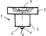
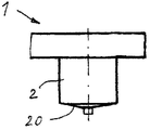
도 1은 연결 요소 그 자체만을 짧은 원통형 핀이 연결 요소의 맨드릴로부터 돌출되어 있는 상태로 도시하고;
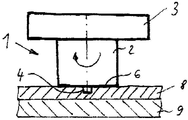
도 2는 도 1의 연결 요소가 두 개의 판형 부품의 상부 부품 위에 배치된 상태를 도시하고;
도 3은 연결 요소가 상부 부품을 관통하고 나서 핀이 크게 변형된 상태를 도시하고;
도 4는 연결 요소와 두 판형 부품들의 마찰 용접 연결이 완료된 상태를 도시하고;
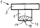
도 5는 센터링부를 둘러싸는 오목부를 구비한 연결 요소를 도시하고;
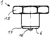
도 6은 중앙 결정부를 구성하는 원뿔형 핀을 구비한 연결 요소를 도시하고;
도 7은 맨드릴이 납작한 원뿔형 횡단 표면을 갖는 연결 요소를 도시하고;
도 8은 중앙 오목부를 구비한 연결 요소를 도시한다. Exemplary embodiments of the invention are shown in the drawings,
1 shows only the connecting element itself with a short cylindrical pin protruding from the mandrel of the connecting element;
2 shows a state in which the connecting element of FIG. 1 is arranged above the upper part of two plate-like parts;
3 shows a state in which the pin is greatly deformed after the connecting element passes through the upper part;
4 shows a state in which the friction welding connection of the connecting element and the two plate parts is completed;
5 shows a connecting element with a recess surrounding the centering portion;
6 shows a connecting element with conical pins constituting a central determinant;
7 shows a connecting element with a mandrel with a flat conical cross surface;
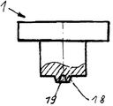
8 shows a connecting element with a central recess.
도 1은 맨드릴(2)과 그 위에 장착된 칼라(3)로 이루어진 연결 요소(1)를 도시한다. 상기 맨드릴의 칼라(3) 반대측에서 맨드릴(2)로부터 돌출된 것은 핀(4)인데, 이 핀은 센터링부를 구성하며 상기 맨드릴(2)과 비교하면 특히 짧고 얇지만 그 형상은 실질적으로 원통형이다. 제조상의 편의를 위해, 핀(4)은 약간 둥근 단부면(5)을 구비하며, 상기 맨드릴(2)의 평평한 횡단 표면(6)으로부터 원통형으로 돌출된다. 또한, 칼라(3)는 여기서는 내부 육각형의 형태를 취하는 공구 홀더(7)를 포함하며, 이 공구 홀더에 적당한 육각형 키가 삽입되어 연결 절차를 위해 연결 요소(1)를 회전시키는 데 사용될 수 있다. 1 shows a connecting
연결 요소(1)의 일 실시예에 따르면, 맨드릴(2)은 길이가 5 내지 6mm이고, 직경이 4 내지 5mm이다. 핀(4)은 길이가 0.5 내지 1mm이고, 직경이 1 내지 2mm이다. 연결 요소의 크기에 따라, 연결 요소의 부품들은 당연히 그 치수가 달라질 수 있다.According to one embodiment of the connecting
도 2는 도 1의 연결 요소(1)와 두 개의 판형 부품이 상기 연결 요소(1)의 횡단 표면(6)이 상부 부품(8)과 접촉되고 핀(4)이 부품(8)의 소재를 막 관통함으로써 부품에 대해 중심 결정 기능을 수행할 수 있는 제1 위치에 있는 상태를 도시한다. 도 2에 도시된 제1 위치에서, 연결 요소(1)는 회전되고, 이에 따라 공지된 방식으로 마찰 용접 공정이 개시된다. 이 상태에서는, 상기 연결 요소(1)의 횡단 표면(6)이 상부 부품(8)을 눌러서 비비게 됨으로써 그에 따라 발생되는 마찰열에 의해 상기 부품(8)이 연화되게 된다. 이에 따라 연결 요소(1)가 부품(8)을 관통하게 되고, 궁극적으로는 연결 요소의 핀(4)이 부품(9)의 표면과 접촉되게 된다. 이러한 관통 공정 중에, 맨드릴(2)이 핀(4)에 의해 중심 결정되고 안내됨으로써 핀(4)의 소재는 연화되어 궁극적으로는 완전히 변형될 것이다.FIG. 2 shows that the
핀(4)이 부품(9)의 면과 접촉되는 제2 위치에서, 핀(4)은 변형되고 이에 따라 도 3에 도시된 것처럼 더욱 넓은 형상(10)을 가질 것이다. 축방향 이동이 진행됨에 따라, 핀은 궁극적으로 완전히 평평해지고, 이에 따라 횡단 표면(6)이 판(9)에 접촉되어 마찰 연결부를 형성할 것이다. 핀의 직경이 작고, 길이가 짧아 그 부피가 작기 때문에, 핀은 마찰 용접 공정을 약화시키지 않을 것이다.In the second position where the
마찰 용접 공정이 연결 요소(1)와 하부 부품(9) 사이에서 완료된 상태가 도 4에 도시되어 있는데, 좁게 해칭된 부분(11)이 마찰 용접 구역이며, 이 마찰 용접 구역을 통해 연결 요소(11)가 하부 부품(9)에 견고하게 연결되고, 연결 요소(1)의 칼라(3)는 상부 부품(8)을 하부 부품(9) 상에 견고하게 가압한다. The state in which the friction welding process is completed between the connecting
도 5는 핀의 구성이 변형된 예를 도시한다. 이 변형례는 칼라(3)와 맨드릴(2)을 갖는 연결 요소(1)로 이루어지고, 핀(13)이 상기 맨드릴(2)의 전방 횡단 표면(12)으로부터 돌출된다. 이 경우, 핀(13)은 환형 오목부(14)에 의해 밀접하게 둘러싸이는데, 이 환형 오목부는 연결 요소(1)가 상부 부품(8)으로 가압됨에 따라 핀(13)으로부터 제거되는 소재를 수용하여 제거된 소재가 맨드릴(2)의 횡단 표면(6)과 상부 부품 간의 후속하는 마찰 용접 공정을 방해하는 것을 방지하는 역할을 한다. 5 shows an example in which the configuration of the pin is modified. This variant consists of a connecting
도 6은 연결 요소(1)의 다른 변형례를 도시하는데, 이 변형례에서는 칼라(15)가 육각형 키에 의해 파지될 수 있는 육각형 헤드로서 표현되어 있다. 이 경우, 핀(16)은 단지 약간만 원뿔형 형상이다. 이 도면에서는 횡단 표면(6)의 가장자리가 판(8)에서 제거된 소재의 배출을 개선시키는 테이퍼진 부분(17)을 갖는 것으로 도시되어 있다. 6 shows another variant of the connecting
도 7은 연결 요소(1)의 변형례를 도시하는데, 이 변형례에서는 맨드릴(2)의 횡단 표면(20)이 납작한 원뿔형 구성으로 이루어져 있다. 7 shows a variant of the connecting
도 8은 연결 요소(1)의 또 다른 변형례를 도시하는데, 이 변형례에서는 그 일부가 횡단면도로 도시된 핀(18)이 내부 오목부(19)를 포함한다. 그로 인해 생성된 핀(18)의 비교적 좁은 가장자리는 핀(18)에 의한 안내를 더욱 강력하게 하고 다른 부품으로의 관통을 용이하게 하는 데에 도움이 될 수 있다. 이 실시예에서는 핀의 직경 역시 2mm 이상일 수 있다.8 shows another variant of the connecting
Claims (5)
상기 센터링부는, 마찰 용접 연결부로 변화되는 상기 맨드릴(2)의 평평한 횡단 표면(6, 12)으로부터 돌출된 핀(4, 13, 16, 18)으로 형성되며, 상부 부품(들)을 관통한 후에 상기 센터링부의 소재가 연화되어 센터링부가 마찰 용접 연결부로 완전히 변화될 수 있도록, 맨드릴(2)의 길이에 비해 짧고 얇게 형성되는 것을 특징으로 하는 연결 요소.Connection element 1 for a friction welding connection for connecting at least two plate-shaped parts 8, 9, the rotating element being rotated and pressurized as the mandrel 2 passes through the upper part (s) 8 ( In the connecting element 1, which has a centering part 4 for determining and guiding the center of 1), the length of the mandrel 2 is adapted to match the thickness of the upper part (s) 8.
The centering portion is formed of pins 4, 13, 16, 18 protruding from the flat transverse surfaces 6, 12 of the mandrel 2, which is transformed into friction welded connections, and after passing through the upper part (s). A connecting element, characterized in that it is formed short and thin compared to the length of the mandrel (2) so that the material of the centering portion is softened so that the centering portion can be completely changed into a friction welding connection.
상기 맨드릴(2)은, 상기 센터링부(13)를 둘러싸며 상기 센터링부(13)로부터 제거된 연화 소재를 수용하는 오목부(14)를 갖는 것을 특징으로 하는 연결 요소.The method of claim 1,
The mandrel (2) is characterized in that it has a recess (14) surrounding the centering portion (13) and containing the softened material removed from the centering portion (13).
상기 핀(4)은 원통형인 것을 특징으로 하는 연결 요소.The method according to claim 1 or 2,
Connecting element, characterized in that the pin (4) is cylindrical.
상기 핀(16)은 원뿔형인 것을 특징으로 하는 연결 요소.The method according to claim 1 or 2,
Connecting element, characterized in that the conical shape.
상기 핀(18)은 중앙 오목부(19)를 갖는 것을 특징으로 하는 연결 요소.5. The method according to any one of claims 1 to 4,
The pin (18) is characterized in that it has a central recess (19).
Applications Claiming Priority (3)
| Application Number | Priority Date | Filing Date | Title |
|---|---|---|---|
| DE102010013229.2 | 2010-03-29 | ||
| DE102010013229A DE102010013229A1 (en) | 2010-03-29 | 2010-03-29 | Connecting element for a friction-welded connection for connecting at least two plate-like components |
| PCT/EP2011/054620 WO2011124482A1 (en) | 2010-03-29 | 2011-03-25 | Connecting element for a friction weld connection for connecting at least two plate-like components |
Publications (1)
| Publication Number | Publication Date |
|---|---|
| KR20130018264A true KR20130018264A (en) | 2013-02-20 |
Family
ID=44169017
Family Applications (1)
| Application Number | Title | Priority Date | Filing Date |
|---|---|---|---|
| KR1020127027244A KR20130018264A (en) | 2010-03-29 | 2011-03-25 | Connecting element for a friction weld connection for connecting at least two plate-like components |
Country Status (10)
| Country | Link |
|---|---|
| US (1) | US20130223921A1 (en) |
| EP (1) | EP2552636B1 (en) |
| JP (1) | JP2013527804A (en) |
| KR (1) | KR20130018264A (en) |
| CN (1) | CN102883849B (en) |
| DE (1) | DE102010013229A1 (en) |
| ES (1) | ES2823295T3 (en) |
| HU (1) | HUE051345T2 (en) |
| PL (1) | PL2552636T3 (en) |
| WO (1) | WO2011124482A1 (en) |
Families Citing this family (5)
| Publication number | Priority date | Publication date | Assignee | Title |
|---|---|---|---|---|
| EP2860407B1 (en) * | 2013-10-08 | 2017-01-18 | MAGNA STEYR Fahrzeugtechnik AG & Co KG | Structured component |
| DE102015202074A1 (en) * | 2015-02-05 | 2016-08-11 | Ejot Gmbh & Co. Kg | Connecting element for producing a component connection |
| JP6411993B2 (en) | 2015-12-25 | 2018-10-24 | 株式会社神戸製鋼所 | Dissimilar material joint structure |
| JP7173376B2 (en) * | 2020-07-31 | 2022-11-16 | Jfeスチール株式会社 | Element, friction element joining method and friction element joining joint manufacturing method |
| EP4279209A1 (en) | 2021-03-24 | 2023-11-22 | JFE Steel Corporation | Element, friction element welding method, and method for manufacturing friction element welded joint |
Family Cites Families (27)
| Publication number | Priority date | Publication date | Assignee | Title |
|---|---|---|---|---|
| US2414270A (en) * | 1944-04-24 | 1947-01-14 | Illinois Tool Works | Fastener device mounting means |
| GB668395A (en) * | 1949-04-21 | 1952-03-19 | English Electric Co Ltd | Improvements relating to studs or the like for use in the process of stud welding |
| US3114031A (en) * | 1961-03-03 | 1963-12-10 | Dash Edward | Welding stud for electric arc welding |
| US3477115A (en) | 1967-03-17 | 1969-11-11 | Caterpillar Tractor Co | Method of fastening parts by friction welding |
| GB1386775A (en) * | 1971-02-11 | 1975-03-12 | Molyneux Eng Co Ltd | Welded stud connections |
| US3975107A (en) * | 1971-02-11 | 1976-08-17 | Molyneux Engineering Company Limited | Anchorage studs |
| CA1177124A (en) * | 1981-11-10 | 1984-10-30 | Jerome H. Tameling | Studs of abrasion resistant metallic material |
| JPS61122490A (en) * | 1984-11-17 | 1986-06-10 | Miura Co Ltd | Stud fin on heat conducting surface |
| DE19620814A1 (en) * | 1996-05-23 | 1997-11-27 | Emhart Inc | Multi-body composite and friction welding process for its manufacture |
| DE19642331C2 (en) * | 1996-10-14 | 2000-10-26 | Daniel Maechtle | Method of making a connection between an anchor rail and an anchor bolt |
| DE19802393A1 (en) * | 1997-06-10 | 1998-12-17 | Emhart Inc | Method and fastening part for forming a friction weld connection |
| DE10014078C5 (en) * | 2000-03-22 | 2007-04-05 | Nelson Bolzenschweiß-Technik GmbH & Co. KG | Method for producing a welding stud |
| US6227433B1 (en) * | 2000-04-04 | 2001-05-08 | The Boeing Company | Friction welded fastener process |
| DE20019602U1 (en) * | 2000-11-15 | 2002-03-28 | Hilbig Schweistechnik Gmbh | welding studs |
| DE20109359U1 (en) * | 2001-06-06 | 2002-10-17 | Hilbig Schweistechnik Gmbh | Light metal studs for friction welding |
| JP3976251B2 (en) * | 2002-06-14 | 2007-09-12 | 本田技研工業株式会社 | Rivet fastening method and rivet fastening device |
| US7452171B2 (en) * | 2003-11-26 | 2008-11-18 | Illinois Tool Works Inc. | Welding stud |
| JP2008506533A (en) * | 2004-07-16 | 2008-03-06 | エー・ヨット・オー・テー・ゲゼルシャフト・ミット・ベシュレンクテル・ハフツング・ウント・コンパニー・コマンディート・ゲゼルシャフト | Fixing elements for friction welding to flat components |
| DE102004034497A1 (en) * | 2004-07-16 | 2006-02-16 | Ejot Gmbh & Co. Kg | Fastening element comprises a face with a concentric annular bead which can be friction welded to a flat component by applying a rotational force |
| DE102006013529B4 (en) | 2005-03-23 | 2019-01-31 | Böllhoff Verbindungstechnik GmbH | Method for joining workpieces |
| US20060213954A1 (en) * | 2005-03-23 | 2006-09-28 | Michael Ruther | Method and joining element for joining workpieces |
| DE202005017524U1 (en) * | 2005-11-09 | 2005-12-29 | Ejot Gmbh & Co. Kg | Pin for friction welding to metal plates has pointed tip whose flanks connect with groove surrounding it, into which molten metal flows during welding, the groove being surrounded on outside by circular rib |
| DE102006003806A1 (en) * | 2006-01-26 | 2007-08-02 | Ejot Gmbh & Co. Kg | Fastening element for Reibschweißverbindung with a flat component |
| US20100288736A1 (en) * | 2007-12-21 | 2010-11-18 | Newfrey Llc | Weld stud |
| DE102008031121A1 (en) * | 2008-05-06 | 2009-11-12 | Daimler Ag | Schweißnietverbindung |
| JP2009285678A (en) * | 2008-05-28 | 2009-12-10 | Kobe Steel Ltd | Dissimilar material joining method and dissimilar material joined body between steel and light alloy, light alloy for joining dissimilar material for steel, and dissimilar material joining rivet between steel and light alloy |
| DE102009006775A1 (en) | 2009-01-30 | 2009-10-01 | Daimler Ag | Rotary friction-welding component used to join workpieces together, includes rounded projection with flat area, cutting edges, slots, polygonal formations or abrasive inclusions |
-
2010
- 2010-03-29 DE DE102010013229A patent/DE102010013229A1/en active Pending
-
2011
- 2011-03-25 HU HUE11713723A patent/HUE051345T2/en unknown
- 2011-03-25 EP EP11713723.2A patent/EP2552636B1/en active Active
- 2011-03-25 KR KR1020127027244A patent/KR20130018264A/en not_active Application Discontinuation
- 2011-03-25 CN CN201180017485.XA patent/CN102883849B/en active Active
- 2011-03-25 JP JP2013501770A patent/JP2013527804A/en active Pending
- 2011-03-25 WO PCT/EP2011/054620 patent/WO2011124482A1/en active Application Filing
- 2011-03-25 US US13/638,446 patent/US20130223921A1/en not_active Abandoned
- 2011-03-25 ES ES11713723T patent/ES2823295T3/en active Active
- 2011-03-25 PL PL11713723T patent/PL2552636T3/en unknown
Also Published As
| Publication number | Publication date |
|---|---|
| PL2552636T3 (en) | 2021-04-06 |
| CN102883849B (en) | 2016-08-03 |
| DE102010013229A1 (en) | 2011-09-29 |
| WO2011124482A1 (en) | 2011-10-13 |
| ES2823295T3 (en) | 2021-05-06 |
| US20130223921A1 (en) | 2013-08-29 |
| EP2552636A1 (en) | 2013-02-06 |
| JP2013527804A (en) | 2013-07-04 |
| HUE051345T2 (en) | 2021-03-01 |
| EP2552636B1 (en) | 2020-07-08 |
| CN102883849A (en) | 2013-01-16 |
Similar Documents
| Publication | Publication Date | Title |
|---|---|---|
| US10384295B2 (en) | Welding auxiliary joining part and method for connecting components by way of said welding auxiliary joining part | |
| KR20130018264A (en) | Connecting element for a friction weld connection for connecting at least two plate-like components | |
| JP5958638B2 (en) | Laser welding method and laser welding apparatus | |
| JP2013527804A5 (en) | ||
| JP2021531439A (en) | A method for manufacturing a plate link chain and a plate link chain having a fixing element forming a protruding nose as a contact. | |
| TW200408484A (en) | Method of welding shaft-like part to stack of steel sheets | |
| CN106660179B (en) | Welding auxiliary joint member, connecting and manufacturing method thereof, mold and manufacturing method thereof | |
| US20210053146A1 (en) | Apparatus for and a method of keyhole free friction stir spot welding | |
| JP5491093B2 (en) | Resistance welding equipment | |
| JP4966516B2 (en) | Drilling device and drilling mold for this drilling device | |
| JP5283028B1 (en) | Metal member joining method and metal member joined body | |
| JP7285556B2 (en) | Apparatus and method for keyhole-free friction stir spot welding | |
| JP7271304B2 (en) | Pierce metal for joining dissimilar materials and method for joining dissimilar materials using the same | |
| KR200364024Y1 (en) | A manufacturing process of ball stud for concentricity improvement of ball and stud | |
| JP2012232326A (en) | Joining object and method of manufacturing the same | |
| JP6578241B2 (en) | Friction stir welding method and friction stir welding apparatus | |
| KR20140013214A (en) | Method for manufacturing cladding materials pipe and the tool | |
| JP4675823B2 (en) | Manufacturing method of end diameter rebar | |
| JP2918859B2 (en) | Burring caulking device | |
| JP6060922B2 (en) | Joining method | |
| JP2009101399A (en) | Spot welding method | |
| CN103111750A (en) | Welding joint and method for improving friction stir welding strength | |
| JP5082248B2 (en) | Laser welding apparatus and laser welding method | |
| KR101586173B1 (en) | Method for manufacturing ball assembly | |
| JP7334561B2 (en) | Butt welding method and apparatus |
Legal Events
| Date | Code | Title | Description |
|---|---|---|---|
| WITN | Application deemed withdrawn, e.g. because no request for examination was filed or no examination fee was paid |