KR20130000012U - railing of scaffolding frame for building - Google Patents
railing of scaffolding frame for building Download PDFInfo
- Publication number
- KR20130000012U KR20130000012U KR2020110005666U KR20110005666U KR20130000012U KR 20130000012 U KR20130000012 U KR 20130000012U KR 2020110005666 U KR2020110005666 U KR 2020110005666U KR 20110005666 U KR20110005666 U KR 20110005666U KR 20130000012 U KR20130000012 U KR 20130000012U
- Authority
- KR
- South Korea
- Prior art keywords
- safety
- sleeve
- locking pin
- railings
- Prior art date
- Legal status (The legal status is an assumption and is not a legal conclusion. Google has not performed a legal analysis and makes no representation as to the accuracy of the status listed.)
- Ceased
Links
- 238000010276 construction Methods 0.000 claims abstract description 19
- 238000003780 insertion Methods 0.000 claims description 4
- 230000037431 insertion Effects 0.000 claims description 4
- 229910000831 Steel Inorganic materials 0.000 description 3
- 238000009434 installation Methods 0.000 description 3
- 230000000452 restraining effect Effects 0.000 description 3
- 239000010959 steel Substances 0.000 description 3
- 230000003111 delayed effect Effects 0.000 description 1
- 230000000694 effects Effects 0.000 description 1
- 230000005283 ground state Effects 0.000 description 1
- 238000000034 method Methods 0.000 description 1
Images

Classifications
-
- E—FIXED CONSTRUCTIONS
- E04—BUILDING
- E04G—SCAFFOLDING; FORMS; SHUTTERING; BUILDING IMPLEMENTS OR AIDS, OR THEIR USE; HANDLING BUILDING MATERIALS ON THE SITE; REPAIRING, BREAKING-UP OR OTHER WORK ON EXISTING BUILDINGS
- E04G5/00—Component parts or accessories for scaffolds
- E04G5/14—Railings
-
- E—FIXED CONSTRUCTIONS
- E04—BUILDING
- E04G—SCAFFOLDING; FORMS; SHUTTERING; BUILDING IMPLEMENTS OR AIDS, OR THEIR USE; HANDLING BUILDING MATERIALS ON THE SITE; REPAIRING, BREAKING-UP OR OTHER WORK ON EXISTING BUILDINGS
- E04G21/00—Preparing, conveying, or working-up building materials or building elements in situ; Other devices or measures for constructional work
- E04G21/32—Safety or protective measures for persons during the construction of buildings
Landscapes
- Engineering & Computer Science (AREA)
- Architecture (AREA)
- Mechanical Engineering (AREA)
- Civil Engineering (AREA)
- Structural Engineering (AREA)
- Steps, Ramps, And Handrails (AREA)
Abstract
본 고안은 안전난간대를 두 개의 제 1, 2안전난간대로 나뉘어 구성한 상태에서 상기 제 1, 2안전난간대를 관절수단으로 접힘 가능하게 연결 구성하여 제 1, 2안전난간대를 접은 상태에서 두 개의 수직프레임 사이에 위치시킨 다음, 하나의 제 1안전난간대를 하나의 수직프레임에 고정시킨 다음, 관절수단으로 연결 구성되어 있는 제 2안전난간대를 펼쳐 제 1안전난간대와 수평으로 동일선상에 위치시킨 상태에서 상기 제 2안전난간대의 반대편의 수직프레임에 고정시킴으로서 두 개의 수직프레임 사이에 안전난간대를 보다 간편하게 조립할 수 있도록 한 건축용 비계 안전 난간대를 구현하고자 한다.The present invention is configured to connect the first and second safety railings by folding the first and second safety railings in a state in which the safety railings are divided into two first and second safety railings so that the first and second safety railings are folded. Then, the first safety railings are fixed to one vertical frame, and then the second safety railings, which are connected by joint means, are unfolded and positioned horizontally on the same line as the first safety railings. The construction of scaffolding safety railings is made to make it easier to assemble safety railings between two vertical frames by fixing them to the vertical frames opposite to the second safety railings.
Description
본 고안은 건축용 비계 안전 난간대에 관련되는 것으로서, 더욱 상세하게는 안전 난간대의 중앙부를 접힘 가능하게 구성하여 안전 난간대를 두 개의 수직프레임 사이에 간편하게 위치시킨 상태에서 조립 구성할 수 있도록 한 건축용 비계 안전 난간대에 관한 것이다.
The present invention relates to a construction scaffolding safety railing, and more particularly, a construction scaffolding safety railing that is configured to be collapsible so that the safety railing can be easily assembled between two vertical frames. It is about.
잘 알려진 바와 같이, 비계는 건축 공사시 작업자들이 높은 곳에서 일할 수 있도록 건축물의 외부에 설치되는 임시가설물을 말하는 것으로서, 대표적으로 강관비계를 예로 들 수 있다.As is well known, scaffolding is a temporary construction installed outside of a building so that workers can work at high places during construction work, for example, steel pipe scaffolding.
상기 강관비계는 내구성이 우수하고 조립 및 해체가 용이한 장점을 가진 것으로서, 통상 수직 및 수평파이프와, 비계발판 그리고 다수개의 클램프들로 구성한다.The steel pipe scaffolding has advantages of excellent durability and easy assembly and disassembly, and is generally composed of vertical and horizontal pipes, scaffolding plates and a plurality of clamps.
상기한 구성품들중 클램프들은 수직 및 수평파이프를 결속하고, 또한 비계발판을 수평파이프상에 지탱시키는 수단으로서, 강관비계의 내구성과 직결되는 가장 중요한 구성요소중의 하나이다.Of the above components, clamps are one of the most important components directly related to the durability of steel pipe scaffolding, as a means of binding the vertical and horizontal pipes and also holding the scaffolding plate on the horizontal pipes.
그러나 종래 건축용 비계에는 기둥부재인 수직프레임 사이 사이에 추락을 방지하는 난간이 없어 발판을 딛고 통행하는 사람이 넘어질 경우 추락을 방지할 수 없는 결점이 있다.However, the conventional construction scaffolding does not have a railing to prevent the fall between the vertical frame, which is a pillar member has a drawback that can not prevent the fall when people pass on the footsteps fall.
한편, 근래 들어서는 환봉 형상의 난간대를 수직프레임 사이에 위치시킨 다음, 클램핑수단을 이용하여 난간대를 수직프레임에 연결시켜 추락을 방지토록 하는 기술이 제안된바 있으나, 종래 클램핑수단은 그 구조가 너무 복잡하여 가설물 설치에 따른 비용을 증가시키는 문제점과 더불어 클램핑수단의 조작이 쉽지않아 설치작업이 지연되는 결과를 초래하게 된다.On the other hand, recently, a technique for preventing a fall by placing a round bar-shaped railing between vertical frames and then connecting the railing to a vertical frame by using clamping means has been proposed, but the conventional clamping means has a complicated structure. In addition to the problem of increasing the cost of the installation of the temporary installation, the operation of the clamping means is not easy, resulting in delayed installation work.
따라서, 상기한 바와 같은 문제점을 해결하기 위한 본 고안의 목적은, 안전 난간대의 중앙부를 접힘 가능하게 구성하여 안전 난간대를 두 개의 수직프레임 사이에 간편하게 위치시킨 상태에서 조립 구성할 수 있도록 한 건축용 비계 안전 난간대를 제공함에 있다.
Accordingly, an object of the present invention for solving the problems as described above, the construction scaffolding safety to configure the safety railings foldable so that the safety railings can be easily assembled between the two vertical frames to configure the construction In providing a handrail.
상술한 목적들을 달성하기 위한 본 고안은 건축용 비계인 기둥부재를 구성하는 두 개의 수직파이프 사이에 수평으로 누운 상태로 설치되는 건축용 비계 안전 난간대에 있어서, 상기 안전난간대는 관절수단을 사이에 두고 양측으로 서로 접힘 가능하게 연결 구성되며 그 양단에는 상기 수직프레임의 체결구멍에 끼워지는 고정핀이 각각 돌출 형성된 제 1, 2안전난간대로 나뉘어 구성하며, 상기 제 1, 2안전난간대를 연결하는 관절수단은 상기 제 1안전난간대의 일단에 돌출 형성되는 메일체결구와, 상기 제 2안전난간대의 일단에 돌출 형성되며 중앙으로 상기 메일체결구가 끼워지기 위한 삽입부를 형성한 상태에서 상기 메일체결구와 힌지 결합되는 핀메일체결구와, 상기 제 2안전난간대의 외경에 돌출 형성되는 걸림핀과, 상기 제 1안전난간대의 외경에 회전 및 전, 후 슬라이드 이동 가능하게 끼워지며 상기 제 1, 2안전난간대의 메일체결구 및 핀메일체결구에 선택적으로 덮혀지는 슬리브와, 상기 슬리브의 일측 둘레면에 형성되며 상기 슬리브의 전진 이동에 따라 상기 제 2안전난간대의 걸림핀을 통과시키는 걸림핀 안내홀 및 상기 걸림핀 안내홀의 일측에 수직으로 절곡 형성되며 상기 슬리브의 회전 동작에 따라 상기 걸림핀 안내홀을 통과한 걸림핀이 걸려질 수 있도록 하는 걸림핀 걸이홀을 포함하여 구성함을 특징으로 한다.
The present invention for achieving the above object is in the construction scaffolding safety railings horizontally laid between two vertical pipes constituting the pillar member which is a building scaffold, the safety railings on both sides with the joint means between It is configured to be connected to each other foldable at both ends are divided into first and second safety handrails each having a fixed pin fitted into the fastening hole of the vertical frame is formed, respectively, the joint means for connecting the first and second safety handrails is The pin mail is hinged and coupled to the mail fastener in a state in which a mail fastener is formed protruding at one end of the first safety handrail, and an insertion part is formed protruding at one end of the second safety handrail and is fitted into the center of the mail fastener. Fasteners, engaging pins protruding from the outer diameter of the second safety handrail, and the outer diameter of the first safety handrail. A sleeve which is fitted to be slidable before and after the slide and is selectively covered by the mail fasteners and the pin mail fasteners of the first and second safety handrails, and is formed on one circumferential surface of the sleeve and is adapted to the forward movement of the sleeve. Accordingly, the locking pin guide hole for passing the locking pin of the second safety handrail and the locking pin guide hole are vertically bent, and the locking pin passing through the locking pin guide hole may be caught according to the rotation of the sleeve. Characterized by a configuration including a locking pin to hang the hole.
본 고안은 안전난간대를 두개의 제 1, 2안전난간대로 나뉘어 구성한 상태에서 상기 제 1, 2안전난간대를 관절수단으로 접힘 가능하게 연결 구성하여 두 개의 수직프레임 사이에 안전난간대를 보다 간편하게 조립할 수 있는 작용효과를 구현한다.
The present invention can be more easily assembled between two vertical frames by connecting the first and second safety railings so that the first and second safety railings can be folded by joint means in a state in which the safety railings are divided into two first and second safety railings. Implement the effect.
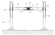
도 1은 본 고안의 바람직한 실시 예에 따른 건축용 비계 안전 난간대의 전체 구성을 도시한 도면.
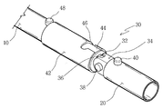
도 2는 도 1에서 도시하고 있는 건축용 비계 안전 난간대에서 관절수단의 구성을 입체적으로 도시한 도면.
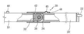
도 3은 도 2에서 도시하고 있는 관절수단의 단면도.
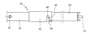
도 4는 도 3의 접힘 상태도.
도 5 내지 도 7은 본 고안에 따른 관절수단의 동작을 순차적으로 도시한 도면들.1 is a view showing the overall configuration of a construction scaffolding safety railing according to a preferred embodiment of the present invention.
Figure 2 is a three-dimensional view showing the configuration of the joint means in the construction scaffolding handrail shown in FIG.
3 is a cross-sectional view of the joint means shown in FIG.
4 is a folded state of FIG.
5 to 7 are views sequentially showing the operation of the joint means according to the present invention.
이하 본 고안의 실시 예를 첨부된 도면을 참조하여 설명하면 다음과 같다. 후술될 상세한 설명에서는 상술한 기술적 과제를 이루기 위해 본 고안에 있어 대표적인 실시 예를 제시할 것이다. 그리고 본 고안으로 제시될 수 있는 다른 실시 예들은 본 고안의 구성에서 설명으로 대체한다.Hereinafter, embodiments of the present invention will be described with reference to the accompanying drawings. In the following description will be presented a representative embodiment in the present invention to achieve the above technical problem. And other embodiments which may be suggested in the present specification are replaced by descriptions in the constitution of the present invention.
본 고안에서는 안전난간대를 두 개의 제 1, 2안전난간대로 나뉘어 구성한 상태에서 상기 제 1, 2안전난간대를 관절수단으로 접힘 가능하게 연결 구성하여 제 1, 2안전난간대를 접은 상태에서 두 개의 수직프레임 사이에 위치시킨 다음, 하나의 제 1안전난간대를 하나의 수직프레임에 고정시킨 다음, 관절수단으로 연결 구성되어 있는 제 2안전난간대를 펼쳐 제 1안전난간대와 수평으로 동일선상에 위치시킨 상태에서 상기 제 2안전난간대의 반대편의 수직프레임에 고정시킴으로서 두 개의 수직프레임 사이에 안전난간대를 보다 간편하게 조립할 수 있도록 한 건축용 비계 안전 난간대를 구현하고자 한다.
In the present invention, the safety railing is divided into two first and second safety railings, and the first and second safety railings are configured to be foldable by articulating means so that the two vertical frames are folded in the first and second safety railings. Then, the first safety railings are fixed to one vertical frame, and then the second safety railings, which are connected by joint means, are unfolded and positioned horizontally on the same line as the first safety railings. The construction of scaffolding safety railings is made to make it easier to assemble safety railings between two vertical frames by fixing them to the vertical frames opposite to the second safety railings.
이하, 도면들을 참조하여 본 고안의 바람직한 실시 예를 기술하기로 한다.Hereinafter, preferred embodiments of the present invention will be described with reference to the drawings.
도 1은 본 고안의 바람직한 실시 예에 따른 건축용 비계 안전 난간대의 전체 구성을 도시한 도면이다.1 is a view showing the overall configuration of the construction scaffolding safety railings according to a preferred embodiment of the present invention.
도 1에서 도시하고 있는 바와 같이, 본 고안의 건축용 비계 안전 난간대는 건축용 비계인 기둥부재를 구성하는 두 개의 수직프레임(50a, 50b) 사이에 수평 방향으로 설치되며 비계 발판을 딛고 통행하는 사람이 넘어져 추락하지 않도록 하는 안전장비로서, 상기 안전난간대는 제 1, 2안전난간대(10, 20)로 나뉘어 구성한 상태에서 관절수단(30)으로 연결시켜 상기 관절수단(30)을 중심으로 접히거나 펼쳐지도록 구성한다.As shown in Figure 1, the construction scaffolding safety railing of the present invention is installed in the horizontal direction between the two vertical frames (50a, 50b) constituting the pillar member, which is a construction scaffolding, and people who pass on the scaffolding platform fall down. As safety equipment to prevent falling, the safety railings are configured to be folded or unfolded about the joint means 30 by connecting to the joint means 30 in a state divided into first and
상기 제 1안전난간대(10)의 일단에는 고정핀(12)이 돌출 형성되며, 상기 고정핀(12)은 하나의 수직프레임(50a) 체결구멍(52a)에 끼워지며 고정되도록 하고, 상기 제 2안전난간대(20)의 일단에도 다른 고정핀(22)을 돌출 형성하고, 상기 고정핀(22)은 반대편 수직프레임(50b)의 체결구멍(52b)에 끼워지며 고정되도록 한다.A
이하에서는, 상기 제 1, 2안전난간대(10, 20)를 접힘 가능하게 연결하는 관절수단(30)의 구조에 대하여 구체적으로 기술하기로 한다.Hereinafter, the structure of the joint means 30 for foldably connecting the first and
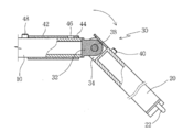
도 2는 도 1에서 도시하고 있는 건축용 비계 안전 난간대에서 관절수단의 구성을 입체적으로 도시한 도면이고, 도 3은 도 2에서 도시하고 있는 관절수단의 단면도이며, 도 4는 도 3의 접힘 상태를 도시한 도면이다.Figure 2 is a three-dimensional view showing the configuration of the joint means in the construction scaffolding safety railing shown in Figure 1, Figure 3 is a cross-sectional view of the joint means shown in Figure 2, Figure 4 shows the folded state of Figure 3 Figure is shown.
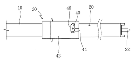
도 2 내지 도 4에서 도시하고 있는 바와 같이, 관절수단(30)은 서로 힌지 결합되는 메일 및 핀메일체결구(32, 34), 걸림핀(40) 그리고 슬리브(42)를 포함하여 구성한다.As shown in Figures 2 to 4, the joint means 30 comprises a mail and
상기 메일체결구(32)는 상기 제 1안전난간대(10)의 단부에 돌출 형성되며, 상기 핀메일체결구(34)는 상기 제 2안전난간대(20)의 단부에 돌출 형성되는 것으로서, 상기 핀메일체결구(34)의 중앙에는 삽입부(36)가 형성되고, 상기 삽입부(36)로 상기 제 1안전난간대(10)의 메일체결구(32)가 삽입된 상태에서 힌지(36) 체결하여 서로 회전 가능하게 연결 구성토록 한다.The
상기 걸림핀(40)은 상기 제 2안전난간대(20)의 외경에 돌출 형성되어, 슬리브(42)의 걸림핀 안내홀(44)을 통과한 후, 걸림핀 안내홀(44)의 일측에 수직으로 절곡 형성되어 있는 걸림핀 걸이홀(46)에 걸려지며 슬리브(42)의 수평 이동을 구속시키는 수단이다.The
상기 슬리브(42)는 상기 제 1안전난간대(10)의 외경에 회전 가능하게 끼워진 상태에서 전방으로 슬라이드 이동하며 상기 제 1안전난간대(10)의 메일체결구(32)와 힌지(36) 결합되어 있는 핀메일체결구(34)가 구비된 제 2안전난간대(20)의 외경에 끼워지며 상기 메일체결구(32) 및 핀메일체결구(34)를 덮어 제 1, 2안전난간대(10, 20)의 접힘을 구속 및 구속 해지시키는 수단이다.The
상기 슬리브(42)의 일측 둘레면에는 걸림핀 안내홀(44)이 형성되고, 상기 걸림핀 안내홀(44)의 일단에는 걸림핀 걸이홀(46)이 수직으로 절곡된 상태로 연장 형성된다.A locking
상기 걸림핀 안내홀(44)에는 상기 슬리브(42)가 전방으로 슬라이드 이동하는 동작에 따라 전술한 제 2안전난간대(20)의 외경에 돌출 형성되어 있는 걸림핀(40)이 통과하게 되고, 상기 걸림핀 걸이홀(46)에는 상기 슬리브(42)의 회전 동작에 따라 상기 걸림핀 안내홀(44)을 통과한 걸림핀(46)이 걸려지며 슬리브(42)의 수평 이동 동작을 구속하게 된다.The locking
상기 제 1안전난간대(10)의 외경에는 스토퍼(48)가 돌출 형성되며, 상기 스토퍼(48)는 상기 슬리브(42)가 후방으로 수평 이동할 때, 슬리브(42)가 일정 길이 이상 밀려나지 않도록 구속하게 된다.
A
이하, 본 고안에 따른 건축용 비계 안전 난간대의 작용을 첨부된 도 1 내지 도 7을 참조하여 기술하기로 한다.Hereinafter, the operation of the building scaffolding safety railing according to the present invention will be described with reference to FIGS. 1 to 7.
먼저, 건축용 비계의 기둥부재인 두 개의 수직프레임(50a, 50b) 사이에 서로 관절수단(30)으로 연결되어 있는 제 1, 2안전난간대(10, 20)를 위치시킨 다음, 상기 제 1안전난간대(10)의 일단에 돌출 형성되어 있는 고정핀(12)을 하나의 수직프레임(50a) 둘레면에 형성되어 있는 체결구멍(52a)에 끼워넣고, 이어서 관절수단(30)을 중심으로 해서 접혀져 있는 제 2안전난간대(20)를 펼쳐 제 1안전난간대(10)와 동일한 수평선상에 위치시킨 다음, 상기 제 2안전난간대(20)의 일단에 돌출 형성되어 있는 고정핀(22)을 반대편에 위치하는 수직프레임(50b)의 둘레면에 형성되어 있는 체결구멍(52b)에 끼워넣어 제 1, 2안전난간대(10, 20)를 두 개의 수직프레임(50a, 50b) 사이에 위치시키도록 한다.First, the first and
즉, 제 1, 2안전난간대(10, 20)는 서로 힌지(38) 결합되어 있는 메일 및 핀메일체결구(32, 34)를 통해 서로 연결 구성되어 상기 힌지(38)를 중심으로 회동하며 접힘 및 펼침 동작을 수행하게 되는 데, 상기 제 1, 2안전난간대(10, 20)의 길이는 수직프레임(50a, 50b) 사이 거리에 맞추어 제작됨에 따라 제 1, 2안전난간대(10, 20)를 접지 않은 상태에서는 수직프레임(50a, 50b) 사이에 조립이 어려운 바, 본 고안은 상기 제 1, 2안전난간대(10, 20)를 관절수단(30)으로 접어 제 1, 2안전난간대(10, 20)의 길이를 줄인 상태에서 수직프레임(50a, 50b) 사이에 위치시킨 다음, 다시 제 1, 2안전난간대(10, 20)를 수평으로 펼쳐 수직프레임(50a, 50b) 사이에 제 1, 2안전난간대(10, 20)를 조립하게 되는 것이다.That is, the first and
구체적으로, 제 1안전난간대(10)의 고정핀(12)을 하나의 수직프레임(50a) 체결구멍(52a)에 끼워넣은 다음, 제 2안전난간대(20)를 들어 올리게 되면 상기 제 2안전난간대(20)는 상기 제 1안전난간대(10)의 메일체결구(32)와 힌지(38) 결합되어 있는 핀메일체결구(34)와 함께 회전하며 제 1안전난간대(10)와 동일한 수평선상에 위치하게 되고, 이 상태에서 슬리브(42)를 전진 이동시키게 되면 제 2안전난간대(20)의 외경에 돌출 형성되어 있는 걸림핀(40)은 상기 슬리브(42)의 걸림핀 안내홀(44)을 통과하게 되며, 이어서, 상기 슬리브(42)의 회전동작에 따라 상기 걸림핀 안내홀(42)의 일측에 수직으로 절곡 형성되어 있는 걸림핀 걸이홀(46)에 걸려지며 슬리브(42)가 후방으로 이동하지 않도록 걸림 고정시키게 된다.Specifically, when the
즉, 상기와 같이 슬리브(42)가 걸림핀(40)에 걸려져 고정되면 상기 슬리브(42)는 힌지(380 결합되어 있는 메일 및 핀메일체결구(32, 34)에 덮혀진 상태로 고정됨에 따라 제 2안전난간대(20)을 접기 위해 힌지(38)를 중심으로 회전시키더라도 상기 슬리브(42)가 핀메일체결구(34)의 회전을 간섭하게 됨으로서 제 2안전난간대(20)가 접히는 것을 구속하게 되는 것이다.That is, when the
한편, 수직프레임(50a, 50b) 사이에 조립되어 있는 제 1, 2안전난간대(10, 20)를 분리하고자 할 때에는 슬리브(42)를 반대 방향으로 회전시켜 걸림핀(40)을 걸림핀 걸이홀(46)에서 빼낸 다음, 상기 슬리브(42)를 후방으로 당겨 이동시키게 되면 상기 제 1, 2안전난간대(10, 20)에서 서로 힌지(38) 결합되어 있는 메일 및 핀메일체결구(32, 34)는 상기 슬리브(42) 외부로 노출되어 지며, 이 상태에서 상기 제 2안전난간대(20)를 아랫 방향으로 밀어주면 상기 핀메일체결구(34)는 힌지(38)를 중심으로 회동하며 제 2안전난간대(34)가 접혀질 수 있도록 하여 제 1, 2안전난간대(10, 20)를 수직프레임(50a, 50b) 사이에서 간편히 조립 해제할 수 있게 되는 것이다.
On the other hand, when the first and
10: 제 1안전 난간대 20: 제 2안전난간대
30: 관절수단 32: 메일체결구
34: 핀메일체결구 38: 힌지
40: 걸림핀 42: 슬리브
44: 걸림핀 안내홀 46: 걸림핀 걸이홀10: first safety railing 20: second safety railing
30: joint means 32: mail fastener
34: Pinmail fastener 38: Hinge
40: engaging pin 42: sleeve
44: locking pin guide hole 46: locking pin hook hole
Claims (1)
상기 안전난간대는 관절수단(30)을 사이에 두고 양측으로 서로 접힘 가능하게 연결 구성되며 그 양단에는 상기 수직프레임(50a, 50b)의 체결구멍(52a, 52b)에 끼워지는 고정핀(12, 20)이 각각 돌출 형성된 제 1, 2안전난간대(10, 20)로 나뉘어 구성하며;
상기 제 1, 2안전난간대(10, 20)를 연결하는 관절수단(30)은;
상기 제 1안전난간대(10)의 일단에 돌출 형성되는 메일체결구(32)와;
상기 제 2안전난간대(20)의 일단에 돌출 형성되며 중앙으로 상기 메일체결구(32)가 끼워지기 위한 삽입부(36)를 형성한 상태에서 상기 메일체결구(32)와 힌지(38) 결합되는 핀메일체결구(34)와;
상기 제 2안전난간대(10, 20)의 외경에 돌출 형성되는 걸림핀(42)과;
상기 제 1안전난간대(10)의 외경에 회전 및 전, 후 슬라이드 이동 가능하게 끼워지며 상기 제 1, 2안전난간대(10, 20)의 메일체결구(32) 및 핀메일체결구(34)에 선택적으로 덮혀지는 슬리브(42)와;
상기 슬리브(42)의 일측 둘레면에 형성되며 상기 슬리브(42)의 전진 이동에 따라 상기 제 2안전난간대(20)의 걸림핀(42)을 통과시키는 걸림핀 안내홀(44) 및 ;
상기 걸림핀 안내홀(44)의 일측에 수직으로 절곡 형성되며 상기 슬리브(42)의 회전 동작에 따라 상기 걸림핀 안내홀(44)을 통과한 걸림핀(42)이 걸려질 수 있도록 하는 걸림핀 걸이홀(46)을 포함하여 구성함을 특징으로 하는 건축용 비계 안전 난간대.
In the construction scaffolding safety railing installed horizontally lying between the two vertical pipe (50a, 50b) constituting the pillar member which is a construction scaffold,
The safety railings are configured to be connected to each other on both sides with the joint means 30 interposed therebetween, and fixing pins 12 and 20 fitted to the fastening holes 52a and 52b of the vertical frames 50a and 50b at both ends thereof. ) Are divided into first and second safety handrails 10 and 20 protruding from each other;
Joint means (30) for connecting the first and second safety railings (10, 20);
A mail fastener 32 protruding from one end of the first safety handrail 10;
The mail fastener 32 and the hinge 38 are coupled to each other in a state in which a protruding portion is formed at one end of the second safety handrail 20 and the insertion part 36 is inserted into the mail fastener 32. Pinmail fastener 34 is to be;
Engaging pins 42 protruding from the outer diameters of the second safety handrails 10 and 20;
It is inserted into the outer diameter of the first safety handrail 10 so as to be movable before and after the slide, and to the mail fastener 32 and the pin mail fastener 34 of the first and second safety handrails 10 and 20. A sleeve 42 optionally covered;
A locking pin guide hole 44 formed at one circumferential surface of the sleeve 42 and passing through the locking pins 42 of the second safety handrail 20 according to the forward movement of the sleeve 42;
The locking pin is formed vertically bent at one side of the locking pin guide hole 44 and allows the locking pin 42 to pass through the locking pin guide hole 44 according to the rotation operation of the sleeve 42. Construction scaffolding safety railings, characterized in that it comprises a hook hole (46).
Priority Applications (1)
| Application Number | Priority Date | Filing Date | Title |
|---|---|---|---|
| KR2020110005666U KR20130000012U (en) | 2011-06-22 | 2011-06-22 | railing of scaffolding frame for building |
Applications Claiming Priority (1)
| Application Number | Priority Date | Filing Date | Title |
|---|---|---|---|
| KR2020110005666U KR20130000012U (en) | 2011-06-22 | 2011-06-22 | railing of scaffolding frame for building |
Publications (1)
| Publication Number | Publication Date |
|---|---|
| KR20130000012U true KR20130000012U (en) | 2013-01-02 |
Family
ID=51357572
Family Applications (1)
| Application Number | Title | Priority Date | Filing Date |
|---|---|---|---|
| KR2020110005666U Ceased KR20130000012U (en) | 2011-06-22 | 2011-06-22 | railing of scaffolding frame for building |
Country Status (1)
| Country | Link |
|---|---|
| KR (1) | KR20130000012U (en) |
Cited By (2)
| Publication number | Priority date | Publication date | Assignee | Title |
|---|---|---|---|---|
| KR101966342B1 (en) * | 2017-11-10 | 2019-04-05 | 박상수 | Folding walking assistance device |
| KR102196163B1 (en) * | 2020-06-12 | 2020-12-29 | 최운성 | Rail connecting device for all weather cover for building construction |
-
2011
- 2011-06-22 KR KR2020110005666U patent/KR20130000012U/en not_active Ceased
Cited By (2)
| Publication number | Priority date | Publication date | Assignee | Title |
|---|---|---|---|---|
| KR101966342B1 (en) * | 2017-11-10 | 2019-04-05 | 박상수 | Folding walking assistance device |
| KR102196163B1 (en) * | 2020-06-12 | 2020-12-29 | 최운성 | Rail connecting device for all weather cover for building construction |
Similar Documents
| Publication | Publication Date | Title |
|---|---|---|
| CN103339332B (en) | Guard rails for elevated working platforms | |
| US11761217B2 (en) | Scaffold gate toeboard assembly for use on a scaffold gate | |
| WO2009127818A1 (en) | Safety unit | |
| US8245816B2 (en) | Integral safety system which can be used for construction | |
| US20180119435A1 (en) | Support member for joinable scaffolding planks | |
| US9260873B1 (en) | Truss member and truss connector | |
| KR20120109170A (en) | Scaffolding ladder | |
| US20170028232A1 (en) | Lifeline device for temporary scaffold and lifeline support device | |
| KR102100695B1 (en) | A device for building safety net the method for installing safety net | |
| KR100828576B1 (en) | Portable frame scaffolding handrail | |
| JP2003147953A (en) | Method and device for installing pipe structure on temporary scaffold | |
| KR101756054B1 (en) | A foldable danger mark apparatus for preventing worker fallng from at lifting gang form | |
| KR102362725B1 (en) | Fall proofing Network Assembly for Window Construction | |
| JP2018044343A (en) | Handrail device | |
| KR20220035885A (en) | Scaffolding safety net fittings | |
| JP4942074B2 (en) | Handrail mounting device | |
| JP2008038588A (en) | Installation method of wire mesh panel and handrail | |
| KR101241444B1 (en) | Portable handrail stanchion | |
| KR102298730B1 (en) | Profile anchor for anti-falling safety hook connection | |
| CN211229470U (en) | Multi-point suspension scaffold | |
| KR20110120158A (en) | Inner unfolding drop prevention net using pulley and ball bearing | |
| JP5249171B2 (en) | Exterior wall construction method using scaffolding, skirting board composite and scaffold | |
| KR200358429Y1 (en) | A foldable scaffold | |
| KR100756538B1 (en) | Aerial work platform | |
| CN207484929U (en) | Scaffold guard rail |
Legal Events
| Date | Code | Title | Description |
|---|---|---|---|
| UA0108 | Application for utility model registration |
Comment text: Application for Utility Model Registration Patent event code: UA01011R08D Patent event date: 20110622 |
|
| UG1501 | Laying open of application | ||
| A201 | Request for examination | ||
| UA0201 | Request for examination |
Patent event date: 20140623 Patent event code: UA02012R01D Comment text: Request for Examination of Application Patent event date: 20110622 Patent event code: UA02011R01I Comment text: Application for Utility Model Registration |
|
| E902 | Notification of reason for refusal | ||
| UE0902 | Notice of grounds for rejection |
Comment text: Notification of reason for refusal Patent event code: UE09021S01D Patent event date: 20150528 |
|
| E601 | Decision to refuse application | ||
| UE0601 | Decision on rejection of utility model registration |
Comment text: Decision to Refuse Application Patent event code: UE06011S01D Patent event date: 20150826 |