KR20120128079A - Hybrid vehicle - Google Patents
Hybrid vehicle Download PDFInfo
- Publication number
- KR20120128079A KR20120128079A KR1020117018296A KR20117018296A KR20120128079A KR 20120128079 A KR20120128079 A KR 20120128079A KR 1020117018296 A KR1020117018296 A KR 1020117018296A KR 20117018296 A KR20117018296 A KR 20117018296A KR 20120128079 A KR20120128079 A KR 20120128079A
- Authority
- KR
- South Korea
- Prior art keywords
- engine
- motor
- output
- hybrid vehicle
- generator
- Prior art date
Links
Images


Classifications
-
- B—PERFORMING OPERATIONS; TRANSPORTING
- B60—VEHICLES IN GENERAL
- B60K—ARRANGEMENT OR MOUNTING OF PROPULSION UNITS OR OF TRANSMISSIONS IN VEHICLES; ARRANGEMENT OR MOUNTING OF PLURAL DIVERSE PRIME-MOVERS IN VEHICLES; AUXILIARY DRIVES FOR VEHICLES; INSTRUMENTATION OR DASHBOARDS FOR VEHICLES; ARRANGEMENTS IN CONNECTION WITH COOLING, AIR INTAKE, GAS EXHAUST OR FUEL SUPPLY OF PROPULSION UNITS IN VEHICLES
- B60K6/00—Arrangement or mounting of plural diverse prime-movers for mutual or common propulsion, e.g. hybrid propulsion systems comprising electric motors and internal combustion engines ; Control systems therefor, i.e. systems controlling two or more prime movers, or controlling one of these prime movers and any of the transmission, drive or drive units Informative references: mechanical gearings with secondary electric drive F16H3/72; arrangements for handling mechanical energy structurally associated with the dynamo-electric machine H02K7/00; machines comprising structurally interrelated motor and generator parts H02K51/00; dynamo-electric machines not otherwise provided for in H02K see H02K99/00
- B60K6/20—Arrangement or mounting of plural diverse prime-movers for mutual or common propulsion, e.g. hybrid propulsion systems comprising electric motors and internal combustion engines ; Control systems therefor, i.e. systems controlling two or more prime movers, or controlling one of these prime movers and any of the transmission, drive or drive units Informative references: mechanical gearings with secondary electric drive F16H3/72; arrangements for handling mechanical energy structurally associated with the dynamo-electric machine H02K7/00; machines comprising structurally interrelated motor and generator parts H02K51/00; dynamo-electric machines not otherwise provided for in H02K see H02K99/00 the prime-movers consisting of electric motors and internal combustion engines, e.g. HEVs
- B60K6/22—Arrangement or mounting of plural diverse prime-movers for mutual or common propulsion, e.g. hybrid propulsion systems comprising electric motors and internal combustion engines ; Control systems therefor, i.e. systems controlling two or more prime movers, or controlling one of these prime movers and any of the transmission, drive or drive units Informative references: mechanical gearings with secondary electric drive F16H3/72; arrangements for handling mechanical energy structurally associated with the dynamo-electric machine H02K7/00; machines comprising structurally interrelated motor and generator parts H02K51/00; dynamo-electric machines not otherwise provided for in H02K see H02K99/00 the prime-movers consisting of electric motors and internal combustion engines, e.g. HEVs characterised by apparatus, components or means specially adapted for HEVs
- B60K6/26—Arrangement or mounting of plural diverse prime-movers for mutual or common propulsion, e.g. hybrid propulsion systems comprising electric motors and internal combustion engines ; Control systems therefor, i.e. systems controlling two or more prime movers, or controlling one of these prime movers and any of the transmission, drive or drive units Informative references: mechanical gearings with secondary electric drive F16H3/72; arrangements for handling mechanical energy structurally associated with the dynamo-electric machine H02K7/00; machines comprising structurally interrelated motor and generator parts H02K51/00; dynamo-electric machines not otherwise provided for in H02K see H02K99/00 the prime-movers consisting of electric motors and internal combustion engines, e.g. HEVs characterised by apparatus, components or means specially adapted for HEVs characterised by the motors or the generators
-
- B—PERFORMING OPERATIONS; TRANSPORTING
- B60—VEHICLES IN GENERAL
- B60K—ARRANGEMENT OR MOUNTING OF PROPULSION UNITS OR OF TRANSMISSIONS IN VEHICLES; ARRANGEMENT OR MOUNTING OF PLURAL DIVERSE PRIME-MOVERS IN VEHICLES; AUXILIARY DRIVES FOR VEHICLES; INSTRUMENTATION OR DASHBOARDS FOR VEHICLES; ARRANGEMENTS IN CONNECTION WITH COOLING, AIR INTAKE, GAS EXHAUST OR FUEL SUPPLY OF PROPULSION UNITS IN VEHICLES
- B60K6/00—Arrangement or mounting of plural diverse prime-movers for mutual or common propulsion, e.g. hybrid propulsion systems comprising electric motors and internal combustion engines ; Control systems therefor, i.e. systems controlling two or more prime movers, or controlling one of these prime movers and any of the transmission, drive or drive units Informative references: mechanical gearings with secondary electric drive F16H3/72; arrangements for handling mechanical energy structurally associated with the dynamo-electric machine H02K7/00; machines comprising structurally interrelated motor and generator parts H02K51/00; dynamo-electric machines not otherwise provided for in H02K see H02K99/00
- B60K6/20—Arrangement or mounting of plural diverse prime-movers for mutual or common propulsion, e.g. hybrid propulsion systems comprising electric motors and internal combustion engines ; Control systems therefor, i.e. systems controlling two or more prime movers, or controlling one of these prime movers and any of the transmission, drive or drive units Informative references: mechanical gearings with secondary electric drive F16H3/72; arrangements for handling mechanical energy structurally associated with the dynamo-electric machine H02K7/00; machines comprising structurally interrelated motor and generator parts H02K51/00; dynamo-electric machines not otherwise provided for in H02K see H02K99/00 the prime-movers consisting of electric motors and internal combustion engines, e.g. HEVs
- B60K6/42—Arrangement or mounting of plural diverse prime-movers for mutual or common propulsion, e.g. hybrid propulsion systems comprising electric motors and internal combustion engines ; Control systems therefor, i.e. systems controlling two or more prime movers, or controlling one of these prime movers and any of the transmission, drive or drive units Informative references: mechanical gearings with secondary electric drive F16H3/72; arrangements for handling mechanical energy structurally associated with the dynamo-electric machine H02K7/00; machines comprising structurally interrelated motor and generator parts H02K51/00; dynamo-electric machines not otherwise provided for in H02K see H02K99/00 the prime-movers consisting of electric motors and internal combustion engines, e.g. HEVs characterised by the architecture of the hybrid electric vehicle
- B60K6/48—Parallel type
- B60K6/485—Motor-assist type
-
- B—PERFORMING OPERATIONS; TRANSPORTING
- B60—VEHICLES IN GENERAL
- B60L—PROPULSION OF ELECTRICALLY-PROPELLED VEHICLES; SUPPLYING ELECTRIC POWER FOR AUXILIARY EQUIPMENT OF ELECTRICALLY-PROPELLED VEHICLES; ELECTRODYNAMIC BRAKE SYSTEMS FOR VEHICLES IN GENERAL; MAGNETIC SUSPENSION OR LEVITATION FOR VEHICLES; MONITORING OPERATING VARIABLES OF ELECTRICALLY-PROPELLED VEHICLES; ELECTRIC SAFETY DEVICES FOR ELECTRICALLY-PROPELLED VEHICLES
- B60L50/00—Electric propulsion with power supplied within the vehicle
- B60L50/10—Electric propulsion with power supplied within the vehicle using propulsion power supplied by engine-driven generators, e.g. generators driven by combustion engines
- B60L50/16—Electric propulsion with power supplied within the vehicle using propulsion power supplied by engine-driven generators, e.g. generators driven by combustion engines with provision for separate direct mechanical propulsion
-
- B—PERFORMING OPERATIONS; TRANSPORTING
- B60—VEHICLES IN GENERAL
- B60W—CONJOINT CONTROL OF VEHICLE SUB-UNITS OF DIFFERENT TYPE OR DIFFERENT FUNCTION; CONTROL SYSTEMS SPECIALLY ADAPTED FOR HYBRID VEHICLES; ROAD VEHICLE DRIVE CONTROL SYSTEMS FOR PURPOSES NOT RELATED TO THE CONTROL OF A PARTICULAR SUB-UNIT
- B60W10/00—Conjoint control of vehicle sub-units of different type or different function
- B60W10/04—Conjoint control of vehicle sub-units of different type or different function including control of propulsion units
- B60W10/06—Conjoint control of vehicle sub-units of different type or different function including control of propulsion units including control of combustion engines
-
- B—PERFORMING OPERATIONS; TRANSPORTING
- B60—VEHICLES IN GENERAL
- B60W—CONJOINT CONTROL OF VEHICLE SUB-UNITS OF DIFFERENT TYPE OR DIFFERENT FUNCTION; CONTROL SYSTEMS SPECIALLY ADAPTED FOR HYBRID VEHICLES; ROAD VEHICLE DRIVE CONTROL SYSTEMS FOR PURPOSES NOT RELATED TO THE CONTROL OF A PARTICULAR SUB-UNIT
- B60W10/00—Conjoint control of vehicle sub-units of different type or different function
- B60W10/04—Conjoint control of vehicle sub-units of different type or different function including control of propulsion units
- B60W10/08—Conjoint control of vehicle sub-units of different type or different function including control of propulsion units including control of electric propulsion units, e.g. motors or generators
-
- B—PERFORMING OPERATIONS; TRANSPORTING
- B60—VEHICLES IN GENERAL
- B60W—CONJOINT CONTROL OF VEHICLE SUB-UNITS OF DIFFERENT TYPE OR DIFFERENT FUNCTION; CONTROL SYSTEMS SPECIALLY ADAPTED FOR HYBRID VEHICLES; ROAD VEHICLE DRIVE CONTROL SYSTEMS FOR PURPOSES NOT RELATED TO THE CONTROL OF A PARTICULAR SUB-UNIT
- B60W10/00—Conjoint control of vehicle sub-units of different type or different function
- B60W10/24—Conjoint control of vehicle sub-units of different type or different function including control of energy storage means
- B60W10/26—Conjoint control of vehicle sub-units of different type or different function including control of energy storage means for electrical energy, e.g. batteries or capacitors
-
- B—PERFORMING OPERATIONS; TRANSPORTING
- B60—VEHICLES IN GENERAL
- B60W—CONJOINT CONTROL OF VEHICLE SUB-UNITS OF DIFFERENT TYPE OR DIFFERENT FUNCTION; CONTROL SYSTEMS SPECIALLY ADAPTED FOR HYBRID VEHICLES; ROAD VEHICLE DRIVE CONTROL SYSTEMS FOR PURPOSES NOT RELATED TO THE CONTROL OF A PARTICULAR SUB-UNIT
- B60W20/00—Control systems specially adapted for hybrid vehicles
- B60W20/10—Controlling the power contribution of each of the prime movers to meet required power demand
-
- B—PERFORMING OPERATIONS; TRANSPORTING
- B60—VEHICLES IN GENERAL
- B60W—CONJOINT CONTROL OF VEHICLE SUB-UNITS OF DIFFERENT TYPE OR DIFFERENT FUNCTION; CONTROL SYSTEMS SPECIALLY ADAPTED FOR HYBRID VEHICLES; ROAD VEHICLE DRIVE CONTROL SYSTEMS FOR PURPOSES NOT RELATED TO THE CONTROL OF A PARTICULAR SUB-UNIT
- B60W30/00—Purposes of road vehicle drive control systems not related to the control of a particular sub-unit, e.g. of systems using conjoint control of vehicle sub-units, or advanced driver assistance systems for ensuring comfort, stability and safety or drive control systems for propelling or retarding the vehicle
- B60W30/18—Propelling the vehicle
- B60W30/188—Controlling power parameters of the driveline, e.g. determining the required power
-
- B—PERFORMING OPERATIONS; TRANSPORTING
- B60—VEHICLES IN GENERAL
- B60K—ARRANGEMENT OR MOUNTING OF PROPULSION UNITS OR OF TRANSMISSIONS IN VEHICLES; ARRANGEMENT OR MOUNTING OF PLURAL DIVERSE PRIME-MOVERS IN VEHICLES; AUXILIARY DRIVES FOR VEHICLES; INSTRUMENTATION OR DASHBOARDS FOR VEHICLES; ARRANGEMENTS IN CONNECTION WITH COOLING, AIR INTAKE, GAS EXHAUST OR FUEL SUPPLY OF PROPULSION UNITS IN VEHICLES
- B60K6/00—Arrangement or mounting of plural diverse prime-movers for mutual or common propulsion, e.g. hybrid propulsion systems comprising electric motors and internal combustion engines ; Control systems therefor, i.e. systems controlling two or more prime movers, or controlling one of these prime movers and any of the transmission, drive or drive units Informative references: mechanical gearings with secondary electric drive F16H3/72; arrangements for handling mechanical energy structurally associated with the dynamo-electric machine H02K7/00; machines comprising structurally interrelated motor and generator parts H02K51/00; dynamo-electric machines not otherwise provided for in H02K see H02K99/00
- B60K6/20—Arrangement or mounting of plural diverse prime-movers for mutual or common propulsion, e.g. hybrid propulsion systems comprising electric motors and internal combustion engines ; Control systems therefor, i.e. systems controlling two or more prime movers, or controlling one of these prime movers and any of the transmission, drive or drive units Informative references: mechanical gearings with secondary electric drive F16H3/72; arrangements for handling mechanical energy structurally associated with the dynamo-electric machine H02K7/00; machines comprising structurally interrelated motor and generator parts H02K51/00; dynamo-electric machines not otherwise provided for in H02K see H02K99/00 the prime-movers consisting of electric motors and internal combustion engines, e.g. HEVs
- B60K6/42—Arrangement or mounting of plural diverse prime-movers for mutual or common propulsion, e.g. hybrid propulsion systems comprising electric motors and internal combustion engines ; Control systems therefor, i.e. systems controlling two or more prime movers, or controlling one of these prime movers and any of the transmission, drive or drive units Informative references: mechanical gearings with secondary electric drive F16H3/72; arrangements for handling mechanical energy structurally associated with the dynamo-electric machine H02K7/00; machines comprising structurally interrelated motor and generator parts H02K51/00; dynamo-electric machines not otherwise provided for in H02K see H02K99/00 the prime-movers consisting of electric motors and internal combustion engines, e.g. HEVs characterised by the architecture of the hybrid electric vehicle
- B60K6/48—Parallel type
- B60K2006/4825—Electric machine connected or connectable to gearbox input shaft
-
- B—PERFORMING OPERATIONS; TRANSPORTING
- B60—VEHICLES IN GENERAL
- B60W—CONJOINT CONTROL OF VEHICLE SUB-UNITS OF DIFFERENT TYPE OR DIFFERENT FUNCTION; CONTROL SYSTEMS SPECIALLY ADAPTED FOR HYBRID VEHICLES; ROAD VEHICLE DRIVE CONTROL SYSTEMS FOR PURPOSES NOT RELATED TO THE CONTROL OF A PARTICULAR SUB-UNIT
- B60W2510/00—Input parameters relating to a particular sub-units
- B60W2510/24—Energy storage means
- B60W2510/242—Energy storage means for electrical energy
- B60W2510/244—Charge state
-
- Y—GENERAL TAGGING OF NEW TECHNOLOGICAL DEVELOPMENTS; GENERAL TAGGING OF CROSS-SECTIONAL TECHNOLOGIES SPANNING OVER SEVERAL SECTIONS OF THE IPC; TECHNICAL SUBJECTS COVERED BY FORMER USPC CROSS-REFERENCE ART COLLECTIONS [XRACs] AND DIGESTS
- Y02—TECHNOLOGIES OR APPLICATIONS FOR MITIGATION OR ADAPTATION AGAINST CLIMATE CHANGE
- Y02T—CLIMATE CHANGE MITIGATION TECHNOLOGIES RELATED TO TRANSPORTATION
- Y02T10/00—Road transport of goods or passengers
- Y02T10/60—Other road transportation technologies with climate change mitigation effect
- Y02T10/62—Hybrid vehicles
-
- Y—GENERAL TAGGING OF NEW TECHNOLOGICAL DEVELOPMENTS; GENERAL TAGGING OF CROSS-SECTIONAL TECHNOLOGIES SPANNING OVER SEVERAL SECTIONS OF THE IPC; TECHNICAL SUBJECTS COVERED BY FORMER USPC CROSS-REFERENCE ART COLLECTIONS [XRACs] AND DIGESTS
- Y02—TECHNOLOGIES OR APPLICATIONS FOR MITIGATION OR ADAPTATION AGAINST CLIMATE CHANGE
- Y02T—CLIMATE CHANGE MITIGATION TECHNOLOGIES RELATED TO TRANSPORTATION
- Y02T10/00—Road transport of goods or passengers
- Y02T10/60—Other road transportation technologies with climate change mitigation effect
- Y02T10/70—Energy storage systems for electromobility, e.g. batteries
-
- Y—GENERAL TAGGING OF NEW TECHNOLOGICAL DEVELOPMENTS; GENERAL TAGGING OF CROSS-SECTIONAL TECHNOLOGIES SPANNING OVER SEVERAL SECTIONS OF THE IPC; TECHNICAL SUBJECTS COVERED BY FORMER USPC CROSS-REFERENCE ART COLLECTIONS [XRACs] AND DIGESTS
- Y02—TECHNOLOGIES OR APPLICATIONS FOR MITIGATION OR ADAPTATION AGAINST CLIMATE CHANGE
- Y02T—CLIMATE CHANGE MITIGATION TECHNOLOGIES RELATED TO TRANSPORTATION
- Y02T10/00—Road transport of goods or passengers
- Y02T10/60—Other road transportation technologies with climate change mitigation effect
- Y02T10/7072—Electromobility specific charging systems or methods for batteries, ultracapacitors, supercapacitors or double-layer capacitors
-
- Y—GENERAL TAGGING OF NEW TECHNOLOGICAL DEVELOPMENTS; GENERAL TAGGING OF CROSS-SECTIONAL TECHNOLOGIES SPANNING OVER SEVERAL SECTIONS OF THE IPC; TECHNICAL SUBJECTS COVERED BY FORMER USPC CROSS-REFERENCE ART COLLECTIONS [XRACs] AND DIGESTS
- Y02—TECHNOLOGIES OR APPLICATIONS FOR MITIGATION OR ADAPTATION AGAINST CLIMATE CHANGE
- Y02T—CLIMATE CHANGE MITIGATION TECHNOLOGIES RELATED TO TRANSPORTATION
- Y02T10/00—Road transport of goods or passengers
- Y02T10/80—Technologies aiming to reduce greenhouse gasses emissions common to all road transportation technologies
- Y02T10/92—Energy efficient charging or discharging systems for batteries, ultracapacitors, supercapacitors or double-layer capacitors specially adapted for vehicles
Abstract
하이브리드 차량은 엔진 및 모터를 구동원으로서 주행 가능하고, 엔진의 배기에 의해 회전 구동되는 배기 터빈과, 배기 터빈에 의해 회전 구동됨으로써 발전하는 발전기를 구비한다. 모터는 발전기에 의해 발전된 전력에 의해 구동된다.The hybrid vehicle includes an exhaust turbine driven by the engine and the motor as a driving source, rotationally driven by the exhaust of the engine, and a generator that is generated by rotationally driven by the exhaust turbine. The motor is driven by the power generated by the generator.
Description
본 발명은 하이브리드 차량에 있어서 엔진의 배기 에너지를 회수하는 기술에 관한 것이다.The present invention relates to a technique for recovering exhaust energy of an engine in a hybrid vehicle.
엔진 및 모터에 의한 하이브리드 시스템은 엔진을 발전 전용으로서 모터의 동력만에 의해 주행하는 시리즈형과, 엔진 및 모터의 동력을 병용하거나 또는 한쪽의 동력만에 의해 주행하는 패럴렐형 및 이들 시리즈형 및 패럴렐형을 합한 시리즈 패럴렐형(스플릿형)으로 분류할 수 있다.The hybrid system based on the engine and the motor is a series type in which the engine is exclusively used for generating power, and a parallel type which uses the power of the engine and the motor together or runs by only one power, and the series type and the parallel type. It can be classified into series parallel type (split type) which combined type.
이와 같은 하이브리드 시스템을 탑재하는 차량에 있어서, JP2000-225871A에는 감속 시나 강판 시에 모터 제너레이터가 차륜측으로부터 구동됨으로써 차량의 운동 에너지나 위치 에너지를 전기 에너지로 변환하여 회수하는 동시에, 회수된 전기 에너지를 이용하여 가속 시에는 엔진을 어시스트하고, 저속 주행 시에는 모터의 동력만으로 주행하는 것이 기재되어 있다.In a vehicle equipped with such a hybrid system, in JP2000-225871A, the motor generator is driven from the wheel side at the time of deceleration or steel sheet, thereby converting and recovering the kinetic energy or potential energy of the vehicle into electrical energy and recovering the recovered electrical energy. It is described that the engine assists at the time of acceleration and travels only by the power of the motor at low speed.
상기와 같은 하이브리드 차량에서는, 회수되는 전기 에너지의 기초는 엔진이 한 일이다. 즉, 회수되는 에너지는 엔진의 정미일로부터 얻어진 전기 에너지이다.In such a hybrid vehicle, the engine is the basis of the recovered electrical energy. In other words, the recovered energy is electrical energy obtained from the net work of the engine.
엔진에 공급된 연료가 갖는 열 에너지 중, 유효하게 동력에 사용되는 비율은 최고에서도 30 내지 34%이다. 한편, 배기로서 버려지는 에너지는 열 에너지(J)와, 압력(P)(㎩)과 유량(V)(㎥)의 곱(PV)(Nm=J)인 동적 에너지이고, 이 열 에너지와 동적 에너지의 합계는 35%에 도달한다. 또한, 냉각계에 버려지는 열은 20 내지 30%, 엔진 표면으로부터 방사되는 비율은 5% 정도이다.Of the thermal energy of the fuel supplied to the engine, the ratio used effectively for power is 30 to 34% at the highest. On the other hand, the energy discarded as exhaust is dynamic energy that is the product (PV) (Nm = J) of the thermal energy J and the pressure P (kPa) and the flow rate V (m 3). The sum of the energy reaches 35%. In addition, the heat | fever thrown away by a cooling system is 20 to 30%, and the ratio radiated | emitted from an engine surface is about 5%.
여기서, 배기의 유량(V)을 단위 시간당의 유량(㎥/s)으로 하면, 압력과 유량의 곱(PV)의 단위는 J/s=W로 된다. 이 배기가 갖는 에너지를 일로 변환하는 방법으로서, 배기 터빈으로 회전 이동력으로서 회수하고, 이 회전 이동력을 기어를 통해 크랭크 샤프트에 전하는 것이 생각된다.Here, when the flow rate V of the exhaust gas is the flow rate per unit time (
그러나, 배기 터빈과 크랭크 샤프트의 회전 속도차가 크기 때문에, 배기 터빈의 회전 속도를 감속하여 전달하는 감속 기구가 복잡해져, 그만큼 마찰의 증가 등에 의해 동력의 일부가 허비된다. 결과적으로 3% 정도밖에 파워 어시스트 효과를 발휘할 수 없다.However, since the rotation speed difference between the exhaust turbine and the crankshaft is large, the deceleration mechanism for slowing down and transmitting the rotation speed of the exhaust turbine becomes complicated, and part of the power is wasted due to the increase in friction. As a result, only about 3% can exert the power assist effect.
본 발명은 엔진의 배기 에너지를 회수하여 종합 열 효율을 향상시키는 것을 목적으로 한다.An object of the present invention is to recover exhaust energy of an engine and to improve overall thermal efficiency.
본 발명의 어느 형태에 따르면, 엔진 및 모터를 구동원으로서 주행 가능한 하이브리드 차량이며, 엔진의 배기에 의해 회전 구동되는 배기 터빈과, 배기 터빈에 의해 회전 구동됨으로써 발전하는 발전기를 구비하고, 모터는 발전기에 의해 발전된 전력에 의해 구동되는 하이브리드 차량이 제공된다.According to one aspect of the present invention, there is provided a hybrid vehicle capable of driving an engine and a motor as a drive source, comprising an exhaust turbine that is rotationally driven by exhaust of the engine, and a generator that is rotated by the exhaust turbine to generate electricity. There is provided a hybrid vehicle driven by the electric power generated by the same.
상기한 형태에 따르면, 엔진의 배기가 갖는 에너지를 배기 터빈으로 회수하고, 회수된 에너지를 전력으로 변환하여 모터를 구동하므로, 모터의 구동분만큼 엔진의 출력을 저하시킬 수 있어, 차량 전체적으로의 종합 열 효율을 향상시킬 수 있다.According to the above aspect, since the energy of the exhaust of the engine is recovered by the exhaust turbine, the recovered energy is converted into electric power to drive the motor, so that the output of the engine can be reduced by the driving amount of the motor, so that the entire vehicle is integrated. The thermal efficiency can be improved.
도 1은 본 발명의 제1 실시 형태에 관한 하이브리드 차량의 구성을 도시하는 개략 구성도이다.
도 2는 모터 컨트롤러로부터 출력되는 3상 구동 전류를 도시하는 도면이다.
도 3은 제어 신호의 흐름 및 에너지의 흐름을 도시하는 도면이다.
도 4는 열 효율 향상 효과에 대해 설명하기 위한 도면이다.
도 5는 열 효율 향상 효과에 대해 설명하기 위한 도면이다.
도 6은 본 발명의 제2 실시 형태에 관한 하이브리드 차량의 구성을 도시하는 개략 구성도이다.
도 7은 본 발명의 제3 실시 형태에 관한 하이브리드 차량의 구성을 도시하는 개략 구성도이다.BRIEF DESCRIPTION OF THE DRAWINGS It is a schematic block diagram which shows the structure of the hybrid vehicle which concerns on 1st Embodiment of this invention.
2 is a diagram showing a three-phase drive current output from the motor controller.
3 is a diagram illustrating the flow of control signals and the flow of energy.
4 is a diagram for explaining a thermal efficiency improving effect.
5 is a diagram for explaining a thermal efficiency improving effect.
6 is a schematic block diagram showing the configuration of a hybrid vehicle according to a second embodiment of the present invention.
7 is a schematic configuration diagram showing a configuration of a hybrid vehicle according to a third embodiment of the present invention.
이하, 첨부 도면을 참조하면서 본 발명의 실시 형태에 대해 설명한다.Hereinafter, embodiments of the present invention will be described with reference to the accompanying drawings.
먼저, 제1 실시 형태에 대해 설명한다.First, the first embodiment will be described.
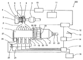
도 1은 본 실시 형태에 있어서의 하이브리드 차량(100)의 구성을 도시하는 개략 구성도이다. 본 실시 형태에 있어서의 하이브리드 차량(100)은 엔진(1), 모터(19) 및 변속기(21)를 이 순서대로 배치하여 구동력 전달 경로를 구성하여, 엔진(1) 및 모터(19) 중 적어도 한쪽의 구동력에 의해 주행 가능하다.FIG. 1: is a schematic block diagram which shows the structure of the
엔진(1)과 모터(19)는 회전 방향으로 직결 상태이고 동일 속도로 회전한다. 모터(19)의 출력측에는 클러치(20)가 배치된다. 토크 컨버터 탑재 차량의 경우에는 클러치(20) 대신에 토크 컨버터가 배치된다. 모터(19) 및 클러치(20)는 벨 하우징(18) 내에 수용된다. 클러치(20)의 출력측에는 변속기(21)가 설치되고, 변속기(21)의 출력측으로부터 유니버설 조인트(22) 및 프로펠러 샤프트(23)를 통해 구동륜으로 동력이 전달된다.The
모터(19)의 로터(28)는 엔진(1)의 크랭크 샤프트(30)에 직결되어 있고, 크랭크 샤프트(30)의 후단부는 클러치(20)에 연결되어 있다. 크랭크 샤프트(30)와 로터(28) 및 클러치(20)는 볼트 등에 의해 체결해도 좋고, 스플라인 결합해도 좋다.The
크랭크 샤프트(30)와 로터(28)는 직결되므로, 변속기(21)에는 엔진(1) 및 모터(19)의 토크가 동일 회전 속도로 입력된다. 즉, 엔진(1) 및 모터(19)의 토크의 합이 변속기(21)에 입력되게 된다.Since the
한편, 코스팅(coasting) 시에는 구동륜으로부터 클러치(20)를 통해 모터(19)가 구동되게 된다. 이에 의해, 구동륜으로부터 엔진(1)에 동력이 전해지는 코스팅 상태에서는 모터(19)를 발전기(3)(모터 제너레이터)로서 작동시킬 수 있다.On the other hand, during coasting (coasting) the
하이브리드 차량(100)은 상기 구성에 추가하여, 엔진(1)의 배기 에너지를 회수하는 배기 터빈(8)과, 배기 터빈(8)의 회전 속도를 감속하여 출력하는 감속기(4)와, 감속기(4)의 출력축에 의해 회전 구동되는 발전기(3)를 구비한다.In addition to the above configuration, the
엔진(1)으로부터의 배기는 배기 매니폴드(2)를 통해 배기 터빈(8)에 급격하게 유입되어, 배기 터빈(8)을 고속으로 회전시킨다. 배기 터빈(8)의 회전은 커플링(5)을 통해 감속기(4)로 전달되어, 1/2 내지 1/6의 회전 속도로 감속하여 발전기(3)를 구동한다.Exhaust from the
커플링(5)은 전열 방지를 위해, 열전도율이 작은 재질, 예를 들어 스테인리스나 세라믹 등으로 이루어진다. 발전기(3)는 고속 회전시킨 쪽이 발전 효율이 양호해 소형화에 기여하므로, 예를 들어 20,000rpm 정도로 회전시킨다.The
배기 터빈(8)과 감속기(4) 사이에 설치되는 어댑터(7)는 배기 터빈(8)으로부터 감속기(4)로의 전열을 방지한다. 어댑터(7)는 내부에 커플링(5)을 수용하여, 커플링(5)을 냉각하는 공기를 도입하기 위한 통풍 구멍(6)을 갖는다.The
또한, 하이브리드 차량(100)은 상기 구성에 추가하여, 배터리(11), 인버터(10), 종합 제어 컨트롤러(14), 모터 컨트롤러(12) 및 엔진 컨트롤러(15)를 구비한다.In addition to the above configuration, the
배터리(11)는 발전기(3)에서 발전된 전력을 축적하는 동시에, 모터(19)에 대해 전력을 공급하는, 고전압용 배터리 또는 캐패시터이다.The
인버터(10)는 발전기(3)에서 발전된 전력을 소정의 전압(예를 들어, 200V)의 직류로 변환하여 모터(19) 또는 배터리(11)로 보낸다. 또한, 인버터(10)는 발전기(3)의 부하를 전기적으로 조정 가능해, 발전 부하를 크게 함으로써 배기 터빈(8)의 회전 속도의 상승을 억제할 수 있다.The
종합 제어 컨트롤러(14)는 액셀러레이터 스텝핑량 검출 센서(13)로부터 송신되는 액셀러레이터 페달의 스텝핑량이나 스텝핑 속도에 기초하여, 그 요구 출력에 대한 엔진(1) 및 모터(19)의 분담 비율을 연산한다.The integrated
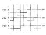
모터 컨트롤러(12)는 종합 제어 컨트롤러(14)로부터의 지령에 기초하여, 배터리(11) 또는 모터(19)로부터 공급되는 전력의 전압이나 주파수를 조정하여 모터(19)의 구동력을 제어한다. 도 2에 도시한 바와 같이, 모터 컨트롤러(12)로부터 출력되는 3상 구동 전류의 각 상 전류는 스테이터의 3상 코일의 각 코일(코일 U, 코일 V, 코일 W)에 각각 공급되어, 스테이터에 회전 자계를 생성한다. 이 회전 자계에 의해 로터(28)의 영구 자석에 회전 토크가 발생하여, 로터(28)의 출력축으로부터 구동력이 출력된다.The
엔진 컨트롤러(15)는 종합 제어 컨트롤러(14)로부터의 지령에 기초하여, 차량용 배터리(16)에 축전된 전력에 의해 스로틀(26)의 개방도, 인젝터(17)의 연료 분사량(펄스 폭) 및 점화 시기를 전자 제어한다. 차량용 배터리(16)는 엔진(1)에 의해 회전 구동되는 알터네이터(27)의 발전 전력을 축전한다.The
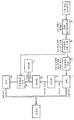
도 3은 하이브리드 차량(100)의 시스템에 있어서의 제어 신호의 흐름 및 에너지의 흐름을 도시한다. 도 3에 있어서, 가는 화살표는 신호, 굵은 화살표는 에너지의 흐름을 나타낸다.3 shows the flow of control signals and the flow of energy in the system of the
엔진(1)의 배기 에너지는 배기 터빈(8)에 의해 회수되어 발전기(3)를 구동한다. 발전기(3)에서 발전한 전력은 인버터(10)에 의해 소정의 전압의 직류로 변환되고, 모터 컨트롤러(12)에 의해 전압이나 주파수가 제어되어 모터(19)가 구동된다. 혹은, 발전기(3)에서 발전한 전력은 배터리(11)에 축전된다.The exhaust energy of the
모터 컨트롤러(12)의 출력 전압이 높아지면, 저항이 일정하면 전류도 전압에 비례하여 증대되게 된다. 따라서, 전력은 전압의 자승에 비례하게 된다. 발전기(3)에서 발전된 전력 중 배터리(11)에 축적되지 않았던 쪽은, 실질적으로 직접 모터 컨트롤러(12)에 의해 제어되어 모터(19)에 공급된다.When the output voltage of the
운전자의 출력(구동력) 요구가 최초로 전달되는 것은 액셀러레이터 페달이고, 액셀러레이터 페달의 스텝핑량이나 스텝핑 속도가 종합 제어 컨트롤러(14)에 입력된다. 종합 제어 컨트롤러(14)는 운전자의 요구 출력을 조달하는 데 필요한, 엔진(1)과 모터(19)의 각각의 출력 분담을 결정한다.The driver's output (driving force) request is first transmitted to the accelerator pedal, and the stepping amount and the stepping speed of the accelerator pedal are input to the
여기서, 배터리(11)의 충전 상태가 소정의 고충전 상태(예를 들어, 80%)보다 높은 상태(풀 충전 또는 이것에 가까운 상태)에서는, 발전기(3)에서 발전한 전력은 배터리(11)에 충전되지 않고 직접 모터 컨트롤러(12)에 공급된다. 배터리(11)의 과충전을 방지하는 간편한 방법으로서, 예를 들어 배터리(11)의 풀 충전 시의 전압이 200V인 경우에는, 인버터(10)의 출구측의 전압을 이것과 대략 동등한 200 내지 205V로 해 두는 것이 생각된다.Here, in a state where the state of charge of the
엔진 컨트롤러(15)는 종합 제어 컨트롤러(14)로 결정된 엔진 출력을 실현하기 위해, 스로틀(26)의 개방도, 인젝터(17)의 연료 분사량(펄스 폭) 및 점화 시기를 전자 제어한다.The
엔진(1)이 운전 상태인 한, 상시 발전되는 전력에 의해 모터(19)가 동력을 발생시키므로, 엔진(1) 및 모터(19)에서 발생하는 동력의 합이 운전자의 요구 출력보다 커지는 경우가 있다. 이 경우에는, 종합 제어 컨트롤러(14)로부터의 신호에 의해 엔진 컨트롤러(15)가 스로틀 액추에이터(25)에 의해 엔진(1)의 흡입 공기량을 스로틀링한다. 흡입 공기량이 줄면 엔진 컨트롤러(15)로 제어되는 인젝터(17)에 가하는 펄스 폭이 자동적으로 좁아져, 흡기 매니폴드(2) 내에 분사되는 연료의 양이 감소된다.As long as the
또한, 엔진(1)이 디젤 엔진인 경우에는 스로틀(26) 및 스로틀 액추에이터(25)가 없으므로, 엔진 컨트롤러(15)는 각 실린더에 배치된 분사 밸브로부터의 연료 분사량을 직접 제어한다.In addition, when the
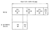
다음에, 열 효율 개선 효과에 대해 도 4를 참조하면서 설명한다. 연료가 갖는 열 에너지를 100%로 한 경우의 열감정을 예로 들면, 다음과 같이 가정한다.Next, the thermal efficiency improvement effect is demonstrated, referring FIG. For example, assume that the thermal emotion in the case where the thermal energy of the fuel is 100% is taken as follows.
엔진(1)의 유효일 (αp) 30%Effective date of engine 1 (αp) 30%
배기 손실 (αe) 35%Exhaust loss (αe) 35%
냉각 손실 (αc) 22%Cooling Loss (αc) 22%
기타 (α0) 13%Others (α0) 13%
α0은 엔진(1) 표면으로부터의 복사에 의한 손실과 기계 손실의 합계이다.α0 is the sum of the losses due to radiation from the
이하, 본 실시 형태의 열 효율 향상 효과를 이들의 값을 사용하여 산출한다.Hereinafter, the thermal efficiency improvement effect of this embodiment is computed using these values.
배기 손실(αe)로부터 회생할 수 있는 전기 에너지(αp')는 배기 터빈(8)의 효율을 ηt, 감속기(4)의 감속 기어의 기계 효율을 ηm, 발전기(3) 및 인버터(10)의 각 효율의 곱을 ηg로 하면, 회생할 수 있는 전기 에너지(αp')는,The electrical energy? P 'that can be regenerated from the exhaust loss? E is? T for the efficiency of the
![]()
![]()
로 된다..
여기서, ηt=0.4, ηm=0.98, ηg=0.9로 하면, αe=0.35이므로 회생되는 전기 에너지(αp')는 0.35×0.4×0.98×0.9=0.12로 된다. 이것이 엔진(1)의 효율에 가산되므로, 엔진(1)으로부터 동력으로서 취출되는 에너지는 αp+αp'=0.3+0.12=0.42로 된다.Here, when? T = 0.4,? M = 0.98, and? G = 0.9, since? E = 0.35, the regenerated electrical energy? P 'is 0.35 x 0.4 x 0.98 x 0.9 = 0.12. Since this is added to the efficiency of the
종래에는 엔진(1)에 공급되는 연료가 갖는 열 에너지가 동력으로 변환되는 비율은 0.3이었지만, 본 실시 형태에 따르면 모터(19)에 의해 0.42로 증대된다. 이는 αp=0.3을 기준으로 하면 (αp+αp')/αp=0.42/0.3=1.4, 즉 40%의 열 효율의 향상으로 된다. 또한, 엔진(1)의 출력이 커짐에 따라서, 회생할 수 있는 전력도 증대되는 것이 본 실시 형태의 특징이다.In the related art, the ratio at which the thermal energy of the fuel supplied to the
αp와 αe가 상술한 바와 같은 값인 경우에는, αe=(0.35/0.3)×αp로 되지만, 운전 조건에 따라서 이 비례 상수(0.35/0.3)가 변화되어도, 반드시 αe와 αp(출력) 사이에는 함수 관계가 성립된다.If αp and αe are the same values as described above, αe = (0.35 / 0.3) × αp, but even if this proportionality constant (0.35 / 0.3) changes depending on the operating conditions, a function must be obtained between αe and αp (output). The relationship is established.
여기서, 엔진(1)에 공급하는 연료의 에너지가 동일하면, 엔진 출력은 αp에 비례한다. 즉, Lp=K×αp, 여기서 Lp는 엔진 출력, K는 비례 상수이다. 또한, 전술한 바와 같이 αe와 αp 사이에 함수 관계가 성립되므로, 수학식 1로부터 αp'도 엔진 출력의 함수로 된다.Here, if the energy of the fuel supplied to the
이 경우, 모터(19)가 발생하는 출력은 0.4Lp로 되므로,In this case, the output generated by the
![]()
![]()
운전자가 요구하는 차량을 움직이는 출력(L)은 수학식 2와 같이 Lp+0.4Lp, 즉 αp+αp'에서 발생시키게 된다.The output L for moving the vehicle required by the driver is generated at Lp + 0.4Lp, that is, αp + αp 'as in
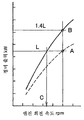
이에 의해, 엔진(1)의 출력은 Lp/(Lp+0.4Lp)=1/1.4=0.71로 충분해진다. 도 5에 도시한 바와 같이, 종래의 엔진 출력이 점선인 경우, 이것에 회생한 전력에 의한 모터(19)의 출력을 더한 파워 유닛의 출력은 실선과 같이 된다. 종래의 엔진 출력(A)은, 본 실시 형태에서는 B로 되므로, 동일한 출력을 얻기 위해서는 A보다 낮은 회전 속도(C)에서 양호하게 된다.Thereby, the output of the
다음에, 연비율(BSFC)의 개선 효과에 대해 설명한다.Next, the improvement effect of fuel efficiency (BSFC) is demonstrated.
열 효율이 30%에 있어서의 엔진(1) 자신의 연비율은 가솔린의 저발열량을 42600kj/㎏으로 하면, 약 280g/kWh이다. 엔진(1)과 모터(19)의 출력의 합은 엔진(1) 단체에 대해 1.4배로 되어 있지만, 소비하는 연료의 질량은 280g으로 바뀌지 않는다. 엔진(1) 및 모터(19)의 출력의 합은 엔진(1) 단체의 출력의 1.4배로 되어 있으므로, 이것으로 소비 연료의 질량을 나눈 종합 BSFC는 280/1.4=200g/kWh로 된다. 연비율은 (280-200)/280=0.286, 즉 약 29% 개선된다.The fuel consumption rate of the
통상의 운전 상태에서는, 운전자의 요구 출력(L)은 엔진(1) 및 모터(19)의 출력의 합으로 조달하는 것이 가능하지만, 급가속이나 급한 등판 시에는 운전자의 요구 출력(L)이 급증하므로, 구동 출력이 부족한 경우가 있다. 이 경우에는, 종합 제어 컨트롤러(14)로부터의 지령으로 배터리(11)에 축적되어 있는 전기 에너지를 더하여 모터(19)의 출력을 증대시킨다.In the normal driving state, the driver's requested output L can be procured by the sum of the outputs of the
모터(19)에 의한 출력 증대이므로, 종래의 터보차와 같이 터보 래그가 발생하거나, 충격적인 토크 변화가 발생하는 일 없이 운전성이 개선된다. 또한, 이 경우에는 배터리(11)로부터의 전력이 가해지므로, αp'를 αp보다 크게 하는 것도 가능하다.Since the output is increased by the
배터리(11)에 전력이 충분히 축적되어 있고, 그 이상 충전할 수 없는 경우(충전 상태가 소정의 고충전 상태보다 높은 경우)에는 엔진(1)의 출력 분담을 줄이고, 모터(19)의 출력을 증대시켜 전력을 소비한다.If the
또한, 발전기(3)에서 발전된 교류의 주파수로부터 배기 터빈(8)의 회전 속도를 검지할 수 있다. 배기 터빈(8)이 과회전인 경우에는, 파워플랜트로서의 출력을 일정하게 유지하면서, 엔진(1)의 출력을 줄이고, 그만큼 모터(19)의 출력 분담을 늘려 발전기(3)의 전기 부하를 증대시킨다. 이에 의해, 터보 엔진(1)의 웨스트 게이트 밸브와 동일한 작용을 발생시킬 수 있다.In addition, the rotation speed of the
아이들링 시에는 피스톤이 한 일이 마찰 손실과 동등하게 되어 있고, 전술한 αp는 0으로 된다. 그러나, 엔진(1)이 회전하고 있는 한 배기 터빈(8)도 회전하여 발전되므로, 아이들링 시에도 전력을 얻을 수 있다.During idling, the work done by the piston is equal to the frictional loss, and αp described above becomes zero. However, since the
이에 의해, 모터(19)로 엔진(1)의 회전을 어시스트하여, 소정의 아이들 회전 속도를 확보하면서 연료를 절감할 수 있다. 또한, 모터(19)로 아이들 회전을 어시스트하므로, 회전 변동이 감소되어 원활한 아이들링이 얻어지고, 아이들링 회전 속도를 저하시키는 것이 가능해진다.As a result, the
이상과 같이 본 실시 형태에서는, 엔진(1)의 배기가 갖는 에너지를 배기 터빈(8)으로 회수하고, 회수된 에너지를 전력으로 변환하여 모터(19)를 구동하므로, 모터(19)의 구동분만큼 엔진(1)의 출력을 저하시킬 수 있고, 엔진(1)에 공급되는 연료의 양을 저감시켜 차량 전체적으로의 종합 열 효율을 향상시킬 수 있다.As described above, in the present embodiment, since the energy of the exhaust of the
따라서, 그만큼 엔진(1)의 배기량을 줄이거나, 파워가 작아지는 린번엔진(1) 차의 운전성을 개선하는 것이 가능해진다.Therefore, it becomes possible to reduce the displacement of the
또한, 운전자의 요구 출력에 기초하여 엔진(1) 및 모터(19)의 출력의 비율을 제어하여, 엔진(1) 및 모터(19)의 출력의 합이 운전자의 요구 출력을 초과하는 경우에는 엔진(1)의 출력을 저하시키고, 출력의 합이 요구 출력에 대해 부족한 경우에는 엔진(1)의 출력을 증대시키므로, 운전자의 요구 출력을 만족시키면서 엔진 출력을 모터 출력에 의해 어시스트할 수 있고, 엔진(1)의 출력을 저하시켜 차량의 종합 열 효율을 향상시킬 수 있다.In addition, the ratio of the output of the
또한, 통상의 운전 시에는 상시 발전되는 전력으로 엔진(1)의 출력을 어시스트하고, 가속시 등 큰 출력이 요구되는 경우에는, 배터리(11)로부터의 전력을 이용하여 모터(19)에 의한 파워 어시스트를 행하므로, 엔진(1)으로부터 배출되는 에너지를 효율적으로 회수할 수 있어, 종합 열 효율을 향상시키는 동시에, 운전자의 요구 출력을 보다 확실하게 발생시킬 수 있다.In addition, the power of the
또한, 배터리(11)의 충전 상태가 소정의 고충전 상태보다 높은 경우에는, 발전기(3)에 의해 발전된 전력을 배터리(11)를 거치지 않고 모터(19)에 직접 공급하므로, 배터리(11)의 과충전에 의한 열화를 방지할 수 있다.In addition, when the state of charge of the
또한, 감속기(4)에 의해 배기 터빈(8)의 회전 속도를 감속하여 발전기(3)로 전달하므로, 발전기(3)를 발전 효율이 좋은 회전 속도로 회전시킬 수 있다.In addition, since the rotation speed of the
또한, 배기 터빈(8)과 감속기(4) 사이에는 커플링(5)을 개재 장착하므로, 배기 터빈(8)의 열이 감속기(4)로 전달되는 것을 방지할 수 있는 동시에, 회전축의 미소한 어긋남을 흡수할 수 있다.Moreover, since the
다음에, 제2 실시 형태에 대해 설명한다.Next, a second embodiment will be described.
도 6은 본 실시 형태에 있어서의 하이브리드 차량(200)의 구성을 도시하는 개략 구성도이다. 본 실시 형태에서는 배터리(11), 모터 컨트롤러(12) 및 종합 제어 컨트롤러(14)를 구비하고 있지 않은 점이 제1 실시 형태와 다르다.6 is a schematic block diagram showing the configuration of the
본 실시 형태에 있어서의 하이브리드 차량(200)은 엔진(1)과 배기 에너지로부터 회생한 전기 에너지로 작동하는 모터(19)를 하나의 파워플랜트로 한 간이한 시스템이다. 발전기(3)에서 발전한 전력은 인버터(10)를 경유하여 직접 모터(19)에 공급된다. 인버터(10)는 교류를 직류로 변환하는 동시에, 발전기(3)에 의해 발전된 전체 전기 에너지를 도 2와 같은 3상의 구형파 전류(3상 구동 전류)로서 모터(19)를 구동한다.The
따라서, 항상 배기 에너지로부터 회생한 전력만으로 모터(19)를 구동하므로, 도 4에서 설명한 바와 같이, 모터(19)의 출력은 항상 엔진(1)의 출력에 비해 작다.Therefore, since the
운전자의 요구 출력은 액셀러레이터 페달의 스텝핑량이나 스텝핑 속도로서 엔진 컨트롤러(15)에 입력되고, 엔진 컨트롤러(15)는 요구 출력에 기초하여, 스로틀(26)의 개방도, 인젝터(17)의 연료 분사량(펄스 폭) 및 점화 시기를 전자 제어한다. 엔진(1)의 출력이 커지면 배기 에너지도 커지므로, 이에 수반하여 발전량이 증가하여 모터(19)의 출력도 증대된다.The driver's required output is input to the
제1 실시 형태와 마찬가지로, 엔진(1) 및 모터(19)의 출력의 합이 운전자의 요구 출력과 동등해지지만, 운전자에게는 개개의 출력 분담은 알 수 없으므로, 엔진(1)만으로 주행하는 차량과 동일한 주행 감각을 실현할 수 있다.Similarly to the first embodiment, the sum of the outputs of the
또한, 배터리(11), 모터 컨트롤러(12) 및 종합 제어 컨트롤러(14)가 불필요하므로, 시스템을 간소화하여 경량화할 수 있다.In addition, since the
다음에, 제3 실시 형태에 대해 설명한다.Next, a third embodiment will be described.
도 7은 본 실시 형태에 있어서의 하이브리드 차량(300)의 구성을 도시하는 개략 구성도이다. 본 실시 형태에서는 클러치(20) 및 모터(19)의 배치가 제1 실시 형태와 다르고, 클러치(20)의 출력측에 모터(19)가 배치된다. 모터(19)의 로터(28)는 변속기(21)에 동력을 전달하는 드라이브 샤프트(29)에 스플라인 등으로 결합된다.7 is a schematic block diagram showing the configuration of a
이에 의해, 클러치(20)를 오프로 한 상태에서 모터(19)에 통전하면 전기 동력만으로 주행(EV 주행)하는 것이 가능하다. 또한, 클러치(20) 대신에, 토크 컨버터가 탑재되는 차량에 있어서는, 코스팅 시에 구동륜으로부터 토크 컨버터의 미끄럼의 영향을 받는 일 없이 직접 운동 에너지를 회생할 수 있다.Thereby, when electricity is supplied to the
제1 실시 형태와 마찬가지로, 종합 제어 컨트롤러(14)는 액셀러레이터 페달의 스텝핑량으로부터 드라이버의 출력 요구값을 연산하여, 엔진(1)과 모터(19)의 출력 분담을 정하고, 모터 컨트롤러(12) 및 엔진 컨트롤러(15)에 출력 제어 신호를 보낸다. 모터 컨트롤러(12)는 모터(19)에 공급하는 전력을 제어하고, 엔진 컨트롤러(15)는 엔진(1)의 출력 성능을 제어한다.Similarly to the first embodiment, the
이상, 본 발명의 실시 형태에 대해 설명하였지만, 상기 실시 형태는 본 발명의 적용예를 나타낸 것에 지나지 않고, 본 발명의 기술적 범위를 상기 실시 형태의 구체적 구성으로 한정하는 취지는 아니다. 본 발명의 취지를 일탈하지 않는 범위에서 다양한 변경이 가능하다.As mentioned above, although embodiment of this invention was described, the said embodiment is only what showed the application example of this invention, and it is not the meaning which limits the technical scope of this invention to the specific structure of the said embodiment. Various changes are possible in the range which does not deviate from the meaning of this invention.
예를 들어, 상기 제1 내지 제3 실시 형태에서는, 배기 터빈(8)의 회전 속도를 감속기(4)에 의해 감속하여 발전기(3)로 전달하고 있지만, 배기 터빈(8)의 직경을 크게 하고, 회전 속도가 20,000rpm 정도로 되도록 설정하면, 감속기(4)를 생략할 수 있다. 이 경우에는, 배기 터빈(8)과 발전기(3)가 커플링(5)으로 직접 연결되어 동일한 회전 속도로 구동할 수 있다.For example, in the said 1st thru | or 3rd embodiment, although the rotational speed of the
본원은 일본 특허청에 2011년 3월 9일에 출원된 일본 특허 출원 제2011-51543호에 기초하는 우선권을 주장하고, 이 출원의 모든 내용은 참조에 의해 본 명세서에 포함된다.
This application claims the priority based on Japanese Patent Application No. 2011-51543 for which it applied to Japan Patent Office on March 9, 2011, and all the content of this application is integrated in this specification by reference.
Claims (9)
상기 엔진의 배기에 의해 회전 구동되는 배기 터빈과,
상기 배기 터빈에 의해 회전 구동됨으로써 발전하는 발전기를 구비하고,
상기 모터는 상기 발전기에 의해 발전된 전력에 의해 구동되는, 하이브리드 차량.It is a hybrid vehicle which can run as an engine and a motor as a driving source,
An exhaust turbine which is rotationally driven by exhaust of the engine,
It is provided with a generator which is generated by rotationally driven by the exhaust turbine,
Wherein the motor is driven by electric power generated by the generator.
상기 모터는 상기 배터리에 축전된 전력에 의해 구동되는, 하이브리드 차량.According to claim 1, further comprising a battery for storing power generated by the generator,
And the motor is driven by electric power stored in the battery.
Applications Claiming Priority (3)
| Application Number | Priority Date | Filing Date | Title |
|---|---|---|---|
| JPJP-P-2011-051543 | 2011-03-09 | ||
| JP2011051543A JP2012187961A (en) | 2011-03-09 | 2011-03-09 | Hybrid vehicle |
| PCT/JP2011/064703 WO2012120702A1 (en) | 2011-03-09 | 2011-06-27 | Hybrid vehicle |
Publications (1)
| Publication Number | Publication Date |
|---|---|
| KR20120128079A true KR20120128079A (en) | 2012-11-26 |
Family
ID=46797691
Family Applications (1)
| Application Number | Title | Priority Date | Filing Date |
|---|---|---|---|
| KR1020117018296A KR20120128079A (en) | 2011-03-09 | 2011-06-27 | Hybrid vehicle |
Country Status (8)
| Country | Link |
|---|---|
| US (1) | US20120329603A1 (en) |
| JP (1) | JP2012187961A (en) |
| KR (1) | KR20120128079A (en) |
| CN (1) | CN102958728A (en) |
| AU (1) | AU2011253649A1 (en) |
| EA (1) | EA201190271A2 (en) |
| TW (1) | TW201236895A (en) |
| WO (1) | WO2012120702A1 (en) |
Cited By (1)
| Publication number | Priority date | Publication date | Assignee | Title |
|---|---|---|---|---|
| KR20190049144A (en) * | 2017-11-01 | 2019-05-09 | 현대자동차주식회사 | Hybrid vehicle and method of controlling air conditioning for the same |
Families Citing this family (11)
| Publication number | Priority date | Publication date | Assignee | Title |
|---|---|---|---|---|
| KR20140044686A (en) * | 2012-10-05 | 2014-04-15 | 현대자동차주식회사 | Hybrid electric vehicle and control method of driving the same |
| WO2014158827A1 (en) | 2013-03-14 | 2014-10-02 | Allison Transmission, Inc. | System and method for compensation of turbo lag in hybrid vehicles |
| US9527499B2 (en) * | 2014-07-17 | 2016-12-27 | GM Global Technology Operations LLC | Power-split hybrid powertrain using turbine generator |
| US9500124B2 (en) | 2014-11-13 | 2016-11-22 | Caterpillar Inc. | Hybrid powertrain and method for operating same |
| FR3033835B1 (en) * | 2015-03-19 | 2019-01-25 | Henri Lescher | ELECTRICITY GENERATING DEVICE FOR INTERNAL COMBUSTION ENGINE OR COMPRESSED AIR MOTOR EQUIPPED WITH SAID DEVICE AND VEHICLE EQUIPPED WITH SAID MOTOR |
| DE102015208859A1 (en) | 2015-05-13 | 2016-11-17 | Mahle International Gmbh | vehicle |
| US11001250B2 (en) * | 2018-03-01 | 2021-05-11 | Cummins Inc. | Waste heat recovery hybrid power drive |
| US11091145B2 (en) * | 2018-05-01 | 2021-08-17 | Ford Global Technologies, Llc | Method and system for engine control |
| EP3640067A1 (en) | 2018-09-26 | 2020-04-22 | Elephant Racing LLC | Control techniques for controlling electric hybrid retrofitted vehicles |
| JP7124736B2 (en) * | 2019-01-30 | 2022-08-24 | トヨタ自動車株式会社 | Mounting structure of drive unit in series hybrid vehicle |
| CN112253308B (en) * | 2020-01-14 | 2021-11-09 | 长城汽车股份有限公司 | Turbo lag power-assisted compensation method, device and equipment and hybrid vehicle |
Family Cites Families (14)
| Publication number | Priority date | Publication date | Assignee | Title |
|---|---|---|---|---|
| DE3676280D1 (en) * | 1985-10-19 | 1991-01-31 | Isuzu Motors Ltd | ENERGY RECOVERY DEVICE FOR A CHARGED INTERNAL COMBUSTION ENGINE. |
| JPH07277014A (en) * | 1994-04-15 | 1995-10-24 | Motor Jidosha Kk | Power transmission device between prime movers of compound prime mover for automobile |
| US6554088B2 (en) * | 1998-09-14 | 2003-04-29 | Paice Corporation | Hybrid vehicles |
| JP3948147B2 (en) | 1999-02-03 | 2007-07-25 | マツダ株式会社 | Hybrid vehicle |
| JP3945370B2 (en) * | 2002-10-25 | 2007-07-18 | トヨタ自動車株式会社 | Car |
| JP2004208420A (en) * | 2002-12-25 | 2004-07-22 | Toyota Motor Corp | Vehicle control device |
| JP4009556B2 (en) * | 2003-05-21 | 2007-11-14 | 三井造船株式会社 | Generator drive shaft structure |
| US20060046894A1 (en) * | 2004-08-09 | 2006-03-02 | Kyle Ronald L | Hybrid vehicle with exhaust powered turbo generator |
| US20100044129A1 (en) * | 2004-08-09 | 2010-02-25 | Hybrid Electric Conversion Co., Llc | Hybrid vehicle formed by converting a conventional ic engine powered vehicle and method of such conversion |
| CN1887612A (en) * | 2006-07-06 | 2007-01-03 | 刘冬生 | Pneumatic and oil-burning mixed powder vehicle |
| KR101359252B1 (en) * | 2006-08-18 | 2014-02-05 | 가부시키가이샤 아쯔미테크 | Drive apparatus for vehicle |
| CN201049586Y (en) * | 2007-05-29 | 2008-04-23 | 比亚迪股份有限公司 | Hybrid power driven system |
| JP2009126303A (en) * | 2007-11-21 | 2009-06-11 | Daihatsu Motor Co Ltd | Vehicle control unit |
| JP5587577B2 (en) | 2009-09-04 | 2014-09-10 | 株式会社ブリヂストン | Rubber crawler |
-
2011
- 2011-03-09 JP JP2011051543A patent/JP2012187961A/en active Pending
- 2011-06-27 AU AU2011253649A patent/AU2011253649A1/en not_active Abandoned
- 2011-06-27 CN CN2011800012535A patent/CN102958728A/en active Pending
- 2011-06-27 KR KR1020117018296A patent/KR20120128079A/en not_active Application Discontinuation
- 2011-06-27 WO PCT/JP2011/064703 patent/WO2012120702A1/en active Application Filing
- 2011-06-27 US US13/386,956 patent/US20120329603A1/en not_active Abandoned
- 2011-06-27 EA EA201190271A patent/EA201190271A2/en unknown
- 2011-08-25 TW TW100130420A patent/TW201236895A/en unknown
Cited By (1)
| Publication number | Priority date | Publication date | Assignee | Title |
|---|---|---|---|---|
| KR20190049144A (en) * | 2017-11-01 | 2019-05-09 | 현대자동차주식회사 | Hybrid vehicle and method of controlling air conditioning for the same |
Also Published As
| Publication number | Publication date |
|---|---|
| EA201190271A2 (en) | 2013-01-30 |
| CN102958728A (en) | 2013-03-06 |
| TW201236895A (en) | 2012-09-16 |
| US20120329603A1 (en) | 2012-12-27 |
| AU2011253649A1 (en) | 2012-09-27 |
| WO2012120702A1 (en) | 2012-09-13 |
| JP2012187961A (en) | 2012-10-04 |
Similar Documents
| Publication | Publication Date | Title |
|---|---|---|
| KR20120128079A (en) | Hybrid vehicle | |
| US10124796B2 (en) | Hybrid vehicle system | |
| US7849840B2 (en) | Electric motor assisted mechanical supercharging system | |
| JP3381613B2 (en) | Drive control device for hybrid vehicle | |
| US5993351A (en) | Control device for hybrid vehicle | |
| US8821342B2 (en) | Accessory drive motor configuration | |
| US7951033B2 (en) | Power unit | |
| US6986727B2 (en) | Retarding control for an electric drive machine | |
| US20060180130A1 (en) | Motor assisted mechanical supercharging system | |
| CN110077220A (en) | A kind of double-motor hybrid drive system and its driving method | |
| CN107415684A (en) | Hybrid electric drive system | |
| WO2012081272A1 (en) | Hybrid vehicle | |
| EP1522450A3 (en) | Engine start and shutdown control in hybrid vehicles | |
| WO2008075130A1 (en) | Power unit for an automotive vehicle and vehicle including such a power unit | |
| JP3565042B2 (en) | Hybrid vehicle control device | |
| KR20160037937A (en) | Dual clutch powertrain architecture | |
| JP6268993B2 (en) | Vehicle control device | |
| JP2012081793A (en) | Control device for hybrid vehicle | |
| CN101659204A (en) | Hybrid driving system and driving method thereof | |
| KR20080016232A (en) | A hybrid type vehicle and its generating control method | |
| US20070080589A1 (en) | Consolidated energy system generator | |
| JP3925498B2 (en) | Control device for hybrid vehicle | |
| JP4986677B2 (en) | Hybrid vehicle | |
| US11458950B2 (en) | Drive force control system for hybrid vehicle | |
| CN101612884B (en) | Hybrid power drive system |
Legal Events
| Date | Code | Title | Description |
|---|---|---|---|
| A201 | Request for examination | ||
| E902 | Notification of reason for refusal | ||
| E90F | Notification of reason for final refusal | ||
| E601 | Decision to refuse application |