KR20120106965A - Method for correcting the combustion settings of a set of combustion chambers and apparatus implementing the method - Google Patents
Method for correcting the combustion settings of a set of combustion chambers and apparatus implementing the method Download PDFInfo
- Publication number
- KR20120106965A KR20120106965A KR1020127016791A KR20127016791A KR20120106965A KR 20120106965 A KR20120106965 A KR 20120106965A KR 1020127016791 A KR1020127016791 A KR 1020127016791A KR 20127016791 A KR20127016791 A KR 20127016791A KR 20120106965 A KR20120106965 A KR 20120106965A
- Authority
- KR
- South Korea
- Prior art keywords
- combustion
- tubes
- chambers
- fuel
- control
- Prior art date
Links
Images


Classifications
-
- F—MECHANICAL ENGINEERING; LIGHTING; HEATING; WEAPONS; BLASTING
- F23—COMBUSTION APPARATUS; COMBUSTION PROCESSES
- F23N—REGULATING OR CONTROLLING COMBUSTION
- F23N5/00—Systems for controlling combustion
- F23N5/003—Systems for controlling combustion using detectors sensitive to combustion gas properties
- F23N5/006—Systems for controlling combustion using detectors sensitive to combustion gas properties the detector being sensitive to oxygen
-
- F—MECHANICAL ENGINEERING; LIGHTING; HEATING; WEAPONS; BLASTING
- F23—COMBUSTION APPARATUS; COMBUSTION PROCESSES
- F23C—METHODS OR APPARATUS FOR COMBUSTION USING FLUID FUEL OR SOLID FUEL SUSPENDED IN A CARRIER GAS OR AIR
- F23C6/00—Combustion apparatus characterised by the combination of two or more combustion chambers or combustion zones, e.g. for staged combustion
- F23C6/02—Combustion apparatus characterised by the combination of two or more combustion chambers or combustion zones, e.g. for staged combustion in parallel arrangement
-
- F—MECHANICAL ENGINEERING; LIGHTING; HEATING; WEAPONS; BLASTING
- F23—COMBUSTION APPARATUS; COMBUSTION PROCESSES
- F23N—REGULATING OR CONTROLLING COMBUSTION
- F23N1/00—Regulating fuel supply
-
- F—MECHANICAL ENGINEERING; LIGHTING; HEATING; WEAPONS; BLASTING
- F23—COMBUSTION APPARATUS; COMBUSTION PROCESSES
- F23N—REGULATING OR CONTROLLING COMBUSTION
- F23N3/00—Regulating air supply or draught
-
- F—MECHANICAL ENGINEERING; LIGHTING; HEATING; WEAPONS; BLASTING
- F23—COMBUSTION APPARATUS; COMBUSTION PROCESSES
- F23N—REGULATING OR CONTROLLING COMBUSTION
- F23N5/00—Systems for controlling combustion
-
- F—MECHANICAL ENGINEERING; LIGHTING; HEATING; WEAPONS; BLASTING
- F23—COMBUSTION APPARATUS; COMBUSTION PROCESSES
- F23N—REGULATING OR CONTROLLING COMBUSTION
- F23N5/00—Systems for controlling combustion
- F23N5/003—Systems for controlling combustion using detectors sensitive to combustion gas properties
-
- F—MECHANICAL ENGINEERING; LIGHTING; HEATING; WEAPONS; BLASTING
- F23—COMBUSTION APPARATUS; COMBUSTION PROCESSES
- F23C—METHODS OR APPARATUS FOR COMBUSTION USING FLUID FUEL OR SOLID FUEL SUSPENDED IN A CARRIER GAS OR AIR
- F23C2201/00—Staged combustion
- F23C2201/20—Burner staging
-
- F—MECHANICAL ENGINEERING; LIGHTING; HEATING; WEAPONS; BLASTING
- F23—COMBUSTION APPARATUS; COMBUSTION PROCESSES
- F23C—METHODS OR APPARATUS FOR COMBUSTION USING FLUID FUEL OR SOLID FUEL SUSPENDED IN A CARRIER GAS OR AIR
- F23C2202/00—Fluegas recirculation
- F23C2202/20—Premixing fluegas with fuel
-
- F—MECHANICAL ENGINEERING; LIGHTING; HEATING; WEAPONS; BLASTING
- F23—COMBUSTION APPARATUS; COMBUSTION PROCESSES
- F23C—METHODS OR APPARATUS FOR COMBUSTION USING FLUID FUEL OR SOLID FUEL SUSPENDED IN A CARRIER GAS OR AIR
- F23C2202/00—Fluegas recirculation
- F23C2202/30—Premixing fluegas with combustion air
-
- F—MECHANICAL ENGINEERING; LIGHTING; HEATING; WEAPONS; BLASTING
- F23—COMBUSTION APPARATUS; COMBUSTION PROCESSES
- F23D—BURNERS
- F23D2203/00—Gaseous fuel burners
- F23D2203/002—Radiant burner mixing tubes
-
- F—MECHANICAL ENGINEERING; LIGHTING; HEATING; WEAPONS; BLASTING
- F23—COMBUSTION APPARATUS; COMBUSTION PROCESSES
- F23N—REGULATING OR CONTROLLING COMBUSTION
- F23N2237/00—Controlling
- F23N2237/02—Controlling two or more burners
Abstract
동일한 연소제(8)와 연료(9) 네트워크에 의해 공급되는 유사한 특징들을 갖는 한 세트의 가열 연소 챔버(2, 2i)들의 실시간 연속 조정을 위한 방법에 대한 것이고, 연소 챔버들 중 하나(2i)가 기준 챔버로서 사용됨에 따라, 연소 변수들이 기준 챔버로부터 매연(fumes) 출력에서 측정되고(7), 모든 챔버(2)들의 제어 변수들이 기준 챔버(2i)의 출력에서 측정된 연소 변수들에 따라, 특히 연소제 및/또는 연료의 연소 및/또는 연료에 대한 연소제의 비율에 따라, 조정된다. To a method for real-time continuous adjustment of a set of heated combustion chambers 2, 2i with similar features supplied by the same combustor 8 and fuel 9 network, one of the combustion chambers 2i Is used as the reference chamber, the combustion variables are measured at the fumes output from the reference chamber (7), and the control variables of all the chambers 2 are determined according to the combustion variables measured at the output of the reference chamber 2i. In particular according to the combustion of the combustor and / or fuel and / or the ratio of the combustor to the fuel.

Description
본 발명은 그 특성들이 변할 수 있는, 연소제와 연료를 공급받는 한 세트의 연소 챔버들에 공급하기 위한 장치들의 조정을 위한 방법에 대한 것이다. 본 발명은 원하는 품질의 연소를 유지하도록 상기 특성들의 발생가능한 변동들을 고려할 수 있게 한다.The present invention is directed to a method for the adjustment of devices for supplying a set of combustion chambers that are supplied with a combustor and fuel whose properties can vary. The present invention makes it possible to take account of possible variations in these properties to maintain combustion of the desired quality.
다수의 산업용 가열 장치들은 연소제와 연료를 공급하기 위한 일반적인 장치에 의해 공급되는 한 세트의 개별적인 연소 챔버들로 구성된다. 예를 들어, 철강 업계에서 이 장치들은 복사관(radiant tube)을 구비한, 금속 편(strip)들을 위한 연속 가공 라인들을 위한 로(furnace)이다. Many industrial heating devices consist of a set of individual combustion chambers supplied by a general device for supplying a combustor and fuel. In the steel industry, for example, these devices are furnaces for continuous processing lines for metal strips with radiant tubes.
많은 경우들에서, 사용되는 연소제들 또는 연료들은 시간에 걸쳐 변할 수 있는 특성들을 갖는다. 예를 들어, 농후한 공기 또는 고갈된 공기(depleted air)를 사용할 때, 또는 심지어 코크스 오븐 가스(coke oven gas), 강철 로 가스(steel furnace gas), 가스들의 혼합물과 같은 현장에서 함께 생성되는 연료들, 또는 바이오가스 또는 발생기 가스(generator gas)와 같은 또 다른 연료들을 사용할 때이다.In many cases, the combustors or fuels used have properties that can vary over time. Fuel produced together, for example, when using rich air or depleted air, or even on-site, such as coke oven gas, steel furnace gas, mixtures of gases Field or other fuels such as biogas or generator gas.
연료의 특성들에 따라 로의 조절을 조정하기 위한 다수의 방법들이 존재한다. 상기 방법들은 연료의 주요 변수들 중 하나, 예를 들어, 발열량(calorific power) PCI, 연소력(combustion power), 연소 지수 또는 웨버(Wobbe) 지수의 변동을 조정할 수 있게 한다. There are a number of ways to adjust the regulation of the furnace depending on the characteristics of the fuel. The methods make it possible to adjust the fluctuations of one of the main variables of fuel, eg calorific power PCI, combustion power, combustion index or Webbe index.
상기 방법들은 대다수의 경우들에서, 샘플링 공정이 연소제와 연료의 특성들을 변경할 때, 연소제와 연료의 특성들이 적절하게 고려될 수 있게 허용하지 않는다. 상기 방법들은 비교적 긴 응답 시간을 갖고 측정용 장치들을 보호된 영역들에서 제 위치에 놓일 것을 요구하는 단점을 또한 갖는다. The methods do, in most cases, do not allow the properties of the combustor and fuel to be properly considered when the sampling process changes the properties of the combustor and fuel. The methods also have the disadvantage of having a relatively long response time and requiring the measuring devices to be put in place in the protected areas.
특정한 하나의 방법이 FR2712961호에 제안되어 있다. 이 방법에 따르면, 연소기(burner)가 소정의 양의 연료를 제거하여 제어되고, 상기 연료는 일정량의 공기와 지정된 챔버에서 연소되어 과잉 공기로 연소되고, 화학량론으로부터 편차를 반영하는 변수가 연료의 완전 연소로부터 매연에서 측정된다. 그 다음에 이 변수는 연소기로부터 연소 공기의 양을 조절하기 위한 계수의 대표값을 결정하는데 사용된다. 상기 연소 측정 장치는 연소 터널, 연소기 및 적절한 측정 수단으로 구성된다.One particular method is proposed in FR2712961. According to this method, a burner is controlled by removing a predetermined amount of fuel, and the fuel is combusted in a predetermined amount of air and a designated chamber to be burned with excess air, and a variable reflecting a deviation from the stoichiometry of the fuel Measured from soot from complete combustion. This variable is then used to determine representative values of the coefficients for adjusting the amount of combustion air from the combustor. The combustion measuring device is composed of a combustion tunnel, a combustor and suitable measuring means.
상기 시스템은 과잉 레벨의 공기를 제공하도록 제어된 비율로 공기/연료 혼합물이 연소되는 특수하게 구성된 소형-로(mini-furnace)를 사용하는 단점을 갖는다. 상기 소형-로는 연료를 소비하고 과잉 레벨로 작동되어야 한다. 이 연소는 예를 들어, 연소기의 출력, 공연비, 로의 온도와 화염의 한정(containment)에 관해, 조절되어야 할 장치의 것과는 매우 상이할 수 있는 작동점에서 상기 소형-로에서 실시된다. 그러므로 이 결과들의 처리는 수학적 수정 공식들의 사용을 필요로 한다.The system has the disadvantage of using a specially configured mini-furnace in which the air / fuel mixture is combusted at a controlled rate to provide excess levels of air. The small furnace consumes fuel and must be operated at an excess level. This combustion is carried out in the small-furnace at an operating point which can be very different from that of the device to be controlled, for example with respect to the combustor output, air-fuel ratio, furnace temperature and flame containment. Therefore, the processing of these results requires the use of mathematical correction formulas.
상기 시스템은 연료의 특성들의 편차를 고려하게 전용으로 지정되는 단점을 또한 갖는다. 이는 연소제의 특성들의 편차 또는 모니터링되는 장치에 적절한 연소 변수들, 즉 미연소 잔류물의 비율 또는 심지어 질산화물 NOx 배출가스의 비율을 고려하지 않는다. The system also has the disadvantage that it is designated exclusively to take into account deviations in the properties of the fuel. It does not take into account deviations in the properties of the combustor or combustion parameters suitable for the monitored device, ie the proportion of unburned residues or even the proportion of nitrous oxide NOx emissions.
본 발명의 목적은 주로 제조 공정에 관련한 한 세트의 연소 챔버들의 연소의 제어를 개선하는 것이고; 특히, 본 발명은 금속편들을 위한 연속 가공 라인에 대한 한 세트의 복사 관들의 제어를 개선하고자 한다.It is an object of the present invention to improve the control of the combustion of a set of combustion chambers, mainly related to the manufacturing process; In particular, the present invention seeks to improve the control of a set of radiation tubes for a continuous machining line for metal pieces.
상기 연소 챔버들은 동일한 타입이다. 상기 연소 챔버들 각각의 출력은 다를 수 있지만 실시되는 기술은 유사하다. 상기 연소 챔버들 간의 잠재적인 차이들은 모니터링되는 것이 바람직한 연소 변수들에 영향을 주지 않는다.The combustion chambers are of the same type. The output of each of the combustion chambers may be different but the techniques implemented are similar. Potential differences between the combustion chambers do not affect the combustion parameters that are desired to be monitored.
한 세트의 복사관들의 연소의 제어를 보장하기 위해, 로 외각(furnace shell)에 설치되는 상기 관들 중 하나가 기준 관으로서 사용된다. 상기 기준 관은 다른 모든 관들과 마찬가지로, 금속편의 가열에 참여한다. 상기 복사 관은 다른 관들의 것과 유사한 구조를 갖고 가열 공정에 참여하는 다른 관들의 작동을 대표하는 방식으로 작용된다. In order to ensure control of the combustion of a set of radiant tubes, one of the tubes installed in the furnace shell is used as reference tube. The reference tube, like all the other tubes, participates in the heating of the metal piece. The radiation tube has a structure similar to that of other tubes and acts in a way that represents the operation of the other tubes participating in the heating process.
복사 관의 출구에서 연소 생성물은 로를 가열하는 공정에 참여하여 냉각된다. 측정 장치가 상기 기준 관의 출구에 설치되고, 상기 측정 장치는 관의 하류측의 연소 생성물들의 상태에 관한 정보를 제공한다. 일반적으로, 상기 장치는 특히 획득될 미연소 잔류물들 및/또는 예를 들어, 과잉 공기에 관한, 정보를 허용하는 가스 분석기이다.At the outlet of the radiation tube the combustion products are cooled by participating in a process of heating the furnace. A measuring device is installed at the outlet of the reference tube, which provides information about the state of combustion products downstream of the tube. In general, the device is a gas analyzer that allows information, in particular regarding unburned residues to be obtained and / or excess air, for example.
그러므로, 본 발명에 따라, 동일한 연소제 및 연료 네트워크들에 의해 공급되는, 유사한 특징들을 갖는 한 세트의 연소 챔버들의 실시간 및 연속적 제어를 위한 방법은:Therefore, according to the invention, a method for real-time and continuous control of a set of combustion chambers with similar features, supplied by the same combustor and fuel networks, is:
- 챔버들 중 하나는 기준 챔버로서 사용되고,One of the chambers is used as a reference chamber,
- 연소 변수들은 기준 챔버의 출구에서의 매연에서 측정되고,Combustion parameters are measured at the soot at the outlet of the reference chamber,
- 모든 챔버들의 제어 변수들은 특히 연소제 대 연료의 비율 및/또는 연소제 및/또는 연료의 조성에 따라, 기준 챔버의 출구에서 측정된 연소 변수들에 따라 조정되는 것을 특징으로 한다. The control parameters of all the chambers are adjusted in particular according to the combustion parameters measured at the outlet of the reference chamber, in particular depending on the ratio of the combustion agent to fuel and / or the composition of the combustion agent and / or fuel.
기준 챔버의 출구에서의 매연에서 측정되는 연소 변수들은 적어도 미연소 잔류물들의 비율 및/또는 질산화물들의 농도 및/또는 수소의 농도 및/또는 이산화탄소의 농도 및/또는 산소의 농도로 구성될 수 있다. The combustion parameters measured at the soot at the outlet of the reference chamber may consist of at least the proportion of unburned residues and / or the concentration of nitrates and / or the concentration of hydrogen and / or the concentration of carbon dioxide and / or the concentration of oxygen.
과잉 공기의 레벨은 기준 챔버의 출구에서의 매연에서 산소 또는 이산화탄소의 농도에 따라 정해질 수 있다. 공기의 부족은 기준 챔버의 출구에서의 매연에서 일산화탄소 또는 수소 또는 미연소 잔류물의 농도에 따라 정해질 수 있다.The level of excess air can be determined by the concentration of oxygen or carbon dioxide at the soot at the outlet of the reference chamber. The lack of air can be determined by the concentration of carbon monoxide or hydrogen or unburned residues at the soot at the outlet of the reference chamber.
유익하게는, 모든 챔버에 대한 제어 변수들은 원하는 레벨의 과잉 공기 및/또는 미연소 잔류물의 비율을 얻도록 조정된다. 미연소 잔류물들의 비율 및/또는 원하는 공기 부족을 얻도록 모든 챔버에 대한 제어 변수들을 조정할 수 있다.Advantageously, the control parameters for all chambers are adjusted to obtain the desired level of excess air and / or unburned residues. The control parameters for all chambers can be adjusted to obtain the ratio of unburned residues and / or the desired air shortage.
질산화물의 농도는 특히, 연소 생성물들로 희석되어, 연소제 및/또는 연료의 조성을 조정하여 조절될 수 있다. The concentration of nitric oxide can be adjusted, in particular, by dilution with combustion products, by adjusting the composition of the combustor and / or fuel.
서멀 챔버(thermal chamber)들은 기준 관의 것과는 상이한 비율들의 가스를 공급받는 복사 관들로 구성될 수 있다. Thermal chambers may consist of radiant tubes fed with gases in different proportions than that of the reference tube.
또한 본 발명은: In addition, the present invention is:
동일한 연소제 및 연료 네트워크들에 의해 공급되는, 유사한 특징들을 갖는 한 세트의 연소 챔버들을 포함하는, 상술한 방법을 실행하기 위한 장치에 관한 것이며, 이 장치는:An apparatus for carrying out the method described above comprising a set of combustion chambers having similar features, supplied by the same combustor and fuel networks, the apparatus:
- 챔버들 중 하나가 기준 챔버로서 사용되고,One of the chambers is used as reference chamber,
- 연소 변수들을 측정하는 수단이 출구에서의 매연에서 상기 연소 변수들을 측정하도록 기준 챔버의 출구에 설치되고,Means for measuring combustion variables is installed at the outlet of the reference chamber to measure the combustion variables at soot at the outlet,
- 특히 연소제 대 연료의 비율 및/또는 연소제 및/또는 연료의 조성에 따라, 기준 챔버의 출구에서 실시된 측정값들에 따라 그 세트의 챔버들의 제어 변수들을 조정하게 제어 수단이 제공되는 것을 특징으로 한다.Control means are provided for adjusting the control parameters of the set of chambers in accordance with the measurements made at the outlet of the reference chamber, in particular in accordance with the ratio of the burner to fuel and / or the composition of the burner and / or fuel. It features.
서멀 챔버들은 복사 관들로 구성될 수 있고, 기준 관이 다른 관들과 함께 공급될 수 있고, 제어 부재들이 모든 관들에 대해 공통인 공급 회로들에 제공된다.The thermal chambers may consist of radiation tubes, the reference tube may be supplied with the other tubes, and the control members are provided in supply circuits common for all the tubes.
다른 가능성에 따라, 복사 관들은 기준 관과는 별개로 공급되고 상이한 공급 회로들에서 기준 관의 것과는 상이한 제어 부재들을 갖고, 관들의 제어 부재들은 상기 관들이 기준 관과 같은 비율의 가스를 공급받도록 제어된다. 추가 가능성에 따라, 복사 관들의 제어 부재들은 상기 관들이 특히 상이한 레벨의 과잉 공기로, 기준 관의 것과는 상이한 비율들의 가스를 공급받도록 제어될 수 있다.According to another possibility, the radiation tubes are supplied separately from the reference tube and have different control members than those of the reference tube in different supply circuits, and the control members of the tubes control such that the tubes are supplied with the same ratio of gas as the reference tube. do. According to a further possibility, the control members of the radiation tubes can be controlled such that the tubes are supplied with different proportions of gas, in particular with different levels of excess air.
종래기술에 사용된 장비에 비해, 본 발명에 따라 표준 장치가 연소 챔버로서 사용되고, 상기 장치는 다른 것들과 유사하고 상기 방법에 사용되고 그 제어는 모든 장치들의 작동을 전적으로 대표한다. 특히, 이는 제어될 전체 장치의 작동 모드에 의존하는 변수들을 허용한다.Compared to the equipment used in the prior art, a standard device is used according to the invention as a combustion chamber, the device being similar to others and used in the method and its control is wholly representative of the operation of all devices. In particular, this allows variables that depend on the mode of operation of the overall device to be controlled.
일반적으로, 주 변수는 산소의 농도에 의해 측정되는 과잉 공기의 레벨이다. 그러나, 다른 변수들, 예를 들어, 로가 차가울 때 미연소 잔류물 또는 예를 들어, 연소제 및/또는 연료의 특성들의 편차들에 따라, 조절될 수 있는 질산화물 배기가스를 모니터링하는 것이 필요할 수 있다. In general, the main variable is the level of excess air measured by the concentration of oxygen. However, depending on other variables, for example unburned residues or variations in the properties of the burner and / or fuel when the furnace is cold, it may be necessary to monitor the nitrous oxide exhaust gas which can be adjusted. have.
본 발명에 따른 방법은 조절될 공기가 없을 때에도 장치가 기능하게 할 수 있다. 이 경우에, 모니터링되는 변수는 매연에서 높은 비율로 존재하는, 이 연소 모드를 나타내는 가스들 중 하나를 표현하는 성분일 수 있다. 이 가스는 예를 들어, 일산화탄소(CO)일 수 있다.The method according to the invention allows the device to function even in the absence of air to be regulated. In this case, the monitored variable may be a component representing one of the gases representing this combustion mode, which is present at a high rate in soot. This gas can be, for example, carbon monoxide (CO).
기준 관은 그 비율이 조정될 수 있게 하는 제어 부재들을 구비하는 연소제 및 연료를 공급하는 회로들에 의해 공급된다. 상기 기준 관은 예를 들어, 연소 매연 또는 산소에 대한 부가적인 회로들에 의해 공급될 수도 있다.The reference tube is supplied by circuits for supplying fuel and a combustor having control members allowing the ratio to be adjusted. The reference tube may for example be supplied by additional circuits for combustion fumes or oxygen.
기준 관의 출구에서 연소 생성물들에 대해 실시된 분석들은 원하는 품질의 연소를 얻도록 공급 회로들의 제어 부재들을 제어하는 것이 고려되었다.Analyzes carried out on the combustion products at the outlet of the reference tube considered controlling the control members of the supply circuits to obtain the desired quality combustion.
기준 관이 다른 관들과 함께 공급될 때, 즉, 제어 부재들이 기준 관을 포함하는 모든 관들에 대해 공통인 공급 회로들에 배치될 때, 다른 관들은 이 동일한 제어로부터 이득을 본다.When the reference tube is fed together with the other tubes, that is, when the control members are placed in supply circuits common to all the tubes including the reference tube, the other tubes benefit from this same control.
복사 관들이 기준 관과 별개로 공급될 때, 즉, 이들이 상이한 공급 회로들에 제어 부재들을 가질 때, 상기 제어 부재들은 상기 관들이 기준 관과 같은 비율들의 가스로, 또는 상이한 비율로 공급되도록 제어된다.When the radiation tubes are fed separately from the reference tube, ie when they have control members in different supply circuits, the control members are controlled such that the tubes are fed in the same proportions of gas as the reference tube, or at different rates. .
두 세트의 복사 관들이 동일한 비율의 가스를 유지하면서, 동일한 제어 변수들, 예를 들어, 상이한 작동 출력에 대해 동일한 공급 압력을 갖도록 설계되면, 기준 관의 제어 변수들은 제 2 세트의 관들의 공급 회로들의 부재들에 대해 복제된다. If the two sets of radiant tubes are designed to have the same control variables, for example the same supply pressure for different operating outputs, while maintaining the same proportion of gas, then the control variables of the reference tube are the supply circuits of the second set of tubes. Is duplicated for the absence of these.
두 세트의 복사 관들이 동일한 비율의 가스를 유지하면서, 상이한 제어 변수들, 예를 들어, 상이한 공급 압력을 갖도록 설계되면, 기준 관의 제어 변수들이 제 2 세트의 관들의 공급 회로들의 부재들에 대해 조정된다. 상기 조정은 측정된 값의 물리적 법칙, 예를 들어, 압력차의 제곱을 사용하는 변화에 따른 유량 변화에 의존한다. If the two sets of radiant tubes are designed to have different control variables, for example different supply pressures, while maintaining the same proportion of gas, then the control variables of the reference tube are relative to the members of the supply circuits of the second set of tubes. Adjusted. The adjustment depends on the change in flow rate with the change using the physical law of the measured value, for example the square of the pressure difference.
본 발명에 따라, 복사관들이 기준 관과 별개로 공급될 때, 그 제어 부재들은 상기 관들이 기준 관의 것과는 상이한 비율들의 가스가, 예를 들어, 상이한 레벨의 과잉 공기가 공급되도록 제어될 수 있다. According to the invention, when the radiating tubes are supplied separately from the reference tube, the control members can be controlled such that the tubes are supplied with different proportions of gas than, for example, different levels of excess air. .
기준 관의 발열 요구조건의 제어는 지속시간을 바꾸거나 유량을 바꿔 실시될 수 있다. 그 제어는 다른 기준 관들의 것과 연계되거나 또는 개별적일 수 있다.Control of the exothermic requirements of the reference tube can be effected by varying the duration or the flow rate. The control may be associated with or separate from that of other reference tubes.
위에 제시한 장치들의 조합과는 별도로, 본 발명은 첨부한 도면들을 참조하여 공개되지만, 어떤 식으로도 제한하는 것이 아닌, 실시예들을 이후에 참조하여 보다 상세히 설명되는 일정 개수의 다른 장치들로 구성된다.
Apart from the combination of devices presented above, the present invention is disclosed with reference to the accompanying drawings, but is not limited in any way, but consists of a number of other devices described in more detail below with reference to embodiments. do.
도 1은 금속 편들의 연속 처리 라인의 개략도.
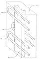
도 2는 복사 관의 개략도.
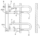
도 3은 한 쌍의 복사 관을 공급하는 제 1 예의 도면.
도 4는 한 세트의 복사 관을 공급하는 제 2 예의 도면.1 is a schematic representation of a continuous processing line of metal pieces.
2 is a schematic view of a radiation tube.
3 shows a first example of supplying a pair of radiation tubes;
4 shows a second example of supplying a set of radiation tubes.
도면들 중 도 1을 참조하면, 도시하지 않은 롤러들을 따라 지나가는, 금속 편(3)의 가열을 제공하는 복사 관(2)들을 구비한, 개략적으로 도시된, 로(1)를 볼 수 있다. 이 가열은 일반적으로 질산화물과 수소의 혼합물로 구성된, 보호 분위기에서 실시된다. 각각의 복사 관에서, 관에 의해 로 외각으로부터 이격된 한정된 연소 챔버에서 연소가 보장된다. 그러므로 간접적 가열이 이루어진다.With reference to FIG. 1 of the drawings, one can see a
도면들 중 도 2를 참조하면, 개략적으로 도시한 바와 같이, U자형 복사 관(2)을 볼 수 있다. 복사 관들은 다른 형상들을 가질 수 있고, 예를 들어, 이들은 I-형상, P-형상, 더블 P-형상, 또는 W-형상일 수 있다. 연소기(4)가 관(2)의 일단부에 위치한다. 화염(5)이 관에서 전파되고 그 에너지를 관의 벽들을 향해 방출하고 이는 그 외곽과 금속편을 가열한다. 이들이 관을 통과할 때, 매연이 관의 벽들을 열적으로 발산시킨다. 열 회복 시스템(도시않음)이 연소 공기가 예열될 수 있게 하고 일반적으로 연소기 반대쪽의 관의 끝에 위치한다. 관의 출구에서, 부분적으로 발산된 매연이 연도(flue)에 연결된 채집기(6)를 향해 배출된다. 관의 출구의 하류측에 위치한 분석기(7)가 연소 생성물들의 분석을 허용한다.Referring to FIG. 2 of the drawings, as schematically shown, a
도면들 중 도 3을 참조하면, 개략적으로 도시한, 기준관(2r)을 포함하는, 한 세트의 U자형 복사 관들에 연소제와 연료를 공급하기 위한 회로의 일 실시예를 볼 수 있다. 연소기(4)들은 제어 밸브(FCVf)로 연료(9)를 공급하는 시스템과 제어 밸브(FCVc)로 연소제(8)를 공급하는 시스템에 의해 공급된다. 밸브들의 자동 제어는 자동화 시스템(도시않음)에 의해 보장될 수 있고 이는 기준 관(2r)의 출구에서 분석기(7)에 의해 측정된 연소 변수들에 대한 정보를 입구에서 수신한다. 자동화 시스템은, 밸브들의 제어부들에 연결된 출구들에서, 입력 데이터의 함수로서 제어를 위한 특정 명령들을 제공한다. Referring to FIG. 3 of the drawings, one embodiment of a circuit for supplying a burner and fuel to a set of U-shaped radiant tubes, including a
이 실시예에서, 로 영역은 복사 관(2)들을 구비하고, 그 연소기(4)들은 공통의 연소제와 연료 네트워크들에 의해 병렬로 공급된다. 발열 요구조건의 변화는 연소기들의 작동 시간, 즉, 각각의 연소기에 대해 소정의 시간 동안 그 연료 밸브(FCVf)와 그 연소제 밸브(FCVc)의 개방 지속시간의 비율에 의해 제어된다.In this embodiment, the furnace area is provided with
각각의 연소기는 이전에는 수동 유량 리미터(10)들에 의해 공지된 작동 점에 대해 시운전(commissioning) 중에 제어되었다. 주어진 작동 점에 대해, 예를 들어, 100% 출력에서, 각각의 연소기는 이전에는 개별적인 유량 리미터 장치에 의해 제어되었다. 이러한 조건들에서, 로 영역의 소정의 일반적인 작동에 대해, 기준 관으로서 선택된 관의 작동은 일반적으로 동일한 공급 시스템에 연결된 세트의 연소기들의 작동을 보인다. 연소제 또는 연료의 특성들의 변화를 고려하도록 기준 관을 공급하는 시스템의 설정들, 즉, 밸브들(FCVc, FCVf)을 조정하여, 모든 복사 관들의 제어가 조정된다.Each combustor was previously controlled during commissioning to a known operating point by
밸브들(FCVc, FCVf)의 제어는 연료의 압력(Pf) 또는 연소제의 압력(Pc)의 변화를 일으켜, 가스들의 비율이 모든 관들과 동일하게 조정되게 할 수 있다.The control of the valves FCVc, FCVf can cause a change in the pressure Pf of the fuel or the pressure Pc of the combustor, such that the proportion of gases is adjusted to be equal to all the tubes.
기준 관의 출구에 배치된 분석기(7)에 의해 실시되는 측정들은 예를 들어, 2개의 변수들에 한정될 수 있다: 미연소 잔류물의 비율과 과잉 연소제의 레벨을 나타내는 산소 함량, 특히 저온에서, 과잉 공기의 레벨에 대해 조정되는 미연소 잔류물의 양.The measurements carried out by the
도면들 중 도 4를 참조하면, 개략적으로 도시한, U자형 복사 관들을 구비한 로를 볼 수 있다.Referring to FIG. 4 of the drawings, a furnace with U-shaped radiation tubes, shown schematically, can be seen.
이 장치에서, 한 세트의 4개의 복사 관(2)들이 제어 밸브들(FCVc, FCVf)에 의해 이 세트의 4개의 관들에 공통인 연소제(8)와 연료(9) 네트워크들에 의해 공급된다. 이 장치에서, 기준 복사 관(2i)이 밸브(FCVfi)에 의해 조절되는 연료(9i)와 밸브(FCVci)에 의해 조절되는 연소제(8i)를 공급하는 자체 시스템에 의해 별개로 공급된다. In this apparatus, a set of four
본 발명의 양호한 실시예에 따라, 조절될 그 세트의 관(2)들과 기준관(2i)에 사용되는 송신기들은 동일한 물리 법칙을 사용한다. 예를 들어, 유량을 측정하기 위해 압력차 송신기를 사용할 수 있다. According to a preferred embodiment of the present invention, the transmitters used for the set of
소정의 작동점에서, 예를 들어, 100% 출력에서, 기준 관의 연소기를 포함하는 각각의 연소기가 이전에는 각각의 연소기에서 동일한 비의 연소제/연료를 얻도록, 특히 수동 제어에 의해, 별개의 유동 제어 장치(10)에 의해 시운전 중에 제어되었다. 이 제어는 모든 관들에 대해 동일한 조건들에서, 즉, 같은 품질의 연소제와 연료로, 실시되었다.At certain operating points, for example, at 100% power, each combustor comprising a combustor of a reference tube previously separates, in particular by manual control, so as to obtain the same ratio of combustor / fuel in each combustor It was controlled during the test run by the
각각의 관이 공칭 출력 및/또는 상이한 치수를 가질 수 있음을 알아야 한다. 관들은 상이한 형상들일 수 있고, 예를 들어, 이들은 U자형 또는 W자형일 수 있다.It should be appreciated that each tube may have a nominal power and / or a different dimension. The tubes can be of different shapes, for example they can be U-shaped or W-shaped.
제어 모드에서, 기준 관으로부터의 연소제와 연료의 유동들이 연료 및/또는 연소제의 특성들의 변화에 따라 매연에서 정확한 산소 비율을 갖도록 조정된다. 분석기(7)는 기준 관에서 원하는 연소 품질을 얻도록 밸브들(FCVci, FCVfi)이 제어될 수 있게 한다. 압력들(Pci, Pfi)로 측정된 상응하는 작동점은 밸브들(FCVc, FCVf)을 제어하는데 사용되는 제어 변수들(Pc, Pf)을 정한다.In the control mode, the flow of combustor and fuel from the reference tube is adjusted to have the correct oxygen ratio in the soot as the fuel and / or the properties of the combustor change. The
기준 관(2i)의 설정이 모든 관에서 원하는 연소를 나타내므로, 그 공급 시스템에서 측정된 값들이 관(2)들의 세트의 조절을 관장하는데 사용된다.Since the setting of the reference tube 2i represents the desired combustion in all the tubes, the values measured in the supply system are used to govern the regulation of the set of
예를 들어, 조절될 세트의 관들에서 연소제의 유동을 나타내는 측정 신호의 값(Iva)이 하기의 관계식에 따라 정의되도록 연소제 밸브(FCVc)가 제어되고 연료 밸브(FCVf)가 발열 요구조건에 따라 제어된다: For example, the combustor valve FCVc is controlled so that the value Iva of the measured signal indicative of the flow of the combustor in the set of tubes to be regulated is defined according to the relationship Is controlled according to:
![]()
![]()
이 관계에서, K는 상수값이고, Ivai는 기준 관(2i)에서 연소제를 나타내는 측정 신호를 표현하고, Ivfi는 기준 관(2i)에서 연료를 나타내는 측정 신호를 표현하고, Ivf는 조절될 관(2)들의 세트에서 연료를 나타내는 측정 신호를 표현한다.In this relationship, K is a constant value, Ivai represents a measurement signal representing a combustion agent in the reference tube 2i, Ivfi represents a measurement signal representing fuel in the reference tube 2i, and Ivf represents a tube to be regulated. Represent the measurement signal representing the fuel in the set of (2).
이 시스템의 장점은 가열 시스템의 조절에 대해 조정이 쉽게 이루어질 수 있게 한다는 것이다. 그러므로 응답 시간이 매우 짧고 제어 변수들이 원하는 제어를 완전히 나타낸다.The advantage of this system is that adjustments can be easily made to the control of the heating system. Therefore the response time is very short and the control variables fully represent the desired control.
이 응용의 확장은 연소제의 조성이 변할 수 있는 장치를 제어하는 것이다. 이러한 변화는 의도한 것이 아닐 수 있고, 예를 들어, 공기의 조성이 습도 함량에 의존한다.An extension of this application is the control of devices in which the composition of the burner can change. This change may not be intended, for example, the composition of the air depends on the humidity content.
이러한 변화는 예를 들어, 연소제의 산소 비율을 조정하여, 의도될 수 있다. 그러므로, 산소 농후화는 로의 출력을 증가시키거나, 연료의 소모를 줄이거나 또는 CO2 배기가스를 줄이도록 실시될 수 있다. 산소 고갈은 NOx 배기가스를 줄이도록, 또는 예를 들어, 화염을 확장하여 열전달을 조정하도록 실시될 수 있다. 이 응용에서, 기준 관의 매연에서 NOx의 측정은 연소제의 희석율을 조절하도록 작용한다. Such a change can be intended, for example, by adjusting the oxygen ratio of the combustor. Therefore, oxygen enrichment can be carried out to increase the output of the furnace, to reduce fuel consumption or to reduce
본 발명은 기준 연소기의 것과 상이할 수 있는 설정들을 조정할 수 있게 한다. 본 발명에 따라, 화염은 다른 챔버와 유사하지만 개방된 공기중에서가 아닌, 기준 챔버에서 형성된다.The invention makes it possible to adjust settings which may differ from that of the reference combustor. According to the invention, the flame is formed in the reference chamber, similar to other chambers but not in open air.
챔버에서의 연소는 그 기하학적 형상에 크게 영향을 받는다. 상기 기하학적 형상은 화염의 한정, 가스 유동의 성질, 매연의 일부의 재순환과 챔버에서 온도 지도제작을 좌우한다. 이러한 변수 모두가 연소, 특히 화염의 온도에 영향을 미친다.Combustion in the chamber is greatly affected by its geometry. The geometry governs the confinement of the flame, the nature of the gas flow, the recycling of some of the soot and the temperature mapping in the chamber. All of these variables affect the combustion, in particular the temperature of the flame.
그러므로 기준 챔버의 출구에서 측정된 연소 결과들이 다른 챔버들에 생성되는 것과 같은 연소를 직접 나타낸다. Therefore the combustion results measured at the outlet of the reference chamber directly represent the same combustion as is produced in the other chambers.
1: 로 2: 복사 관
3: 금속 편 4: 연소기
5: 화염 6: 채집기
7: 분석기 8: 연소제
9: 연료 10: 리미터1: furnace 2: replica tube
3: metal piece 4: combustor
5: flame 6: picker
7: Analyzer 8: Combustion
9: fuel 10: limiter
Claims (12)
- 상기 연소 챔버(2, 2r, 2i)들 중 하나는 기준 챔버로서 사용되고,
- 연소 변수들은 상기 기준 챔버의 출구에서의 매연에서 측정되고(7),
- 모든 챔버들의 제어 변수들은 특히 연소제 대 연료의 비율 및/또는 연소제 및/또는 연료의 조성에 따라, 상기 기준 챔버의 출구에서 측정된 연소 변수들에 따라 조정되는 것을 특징으로 하는 연소 챔버 제어 방법.In a method for real-time and continuous control of a set of heated combustion chambers 2, 2r, 2i with similar features, supplied by the same combustor 8 and fuel 9 networks,
One of the combustion chambers 2, 2r, 2i is used as a reference chamber,
Combustion parameters are measured at the soot at the outlet of the reference chamber (7),
Combustion chamber control, characterized in that the control parameters of all the chambers are adjusted in accordance with the combustion parameters measured at the outlet of the reference chamber, in particular in accordance with the ratio of the combustion agent to fuel and / or the composition of the combustion agent and / or fuel. Way.
상기 기준 챔버의 출구에서의 매연에서 측정되는 상기 연소 변수들은 적어도 미연소 잔류물들의 비율 및/또는 질산화물들의 농도 및/또는 수소의 농도 및/또는 일산화탄소의 농도 및/또는 이산화탄소의 농도 및/또는 산소의 농도로 구성되는 것을 특징으로 하는 연소 챔버 제어 방법.The method of claim 1,
The combustion parameters measured at the soot at the outlet of the reference chamber are at least the proportion of unburned residues and / or the concentration of nitrates and / or the concentration of hydrogen and / or the concentration of carbon monoxide and / or the concentration of carbon dioxide and / or oxygen Combustion chamber control method, characterized in that consisting of.
과잉 공기의 레벨은 상기 기준 챔버의 출구에서의 매연에서 산소 또는 이산화탄소의 농도에 따라 정해지는 것을 특징으로 하는 연소 챔버 제어 방법.The method of claim 2,
The level of excess air is determined by the concentration of oxygen or carbon dioxide at the soot at the outlet of the reference chamber.
공기의 부족이 상기 기준 챔버의 출구에서의 매연 중 일산화탄소 또는 수소 또는 미연소 잔류물들의 농도에 따라 정해지는 것을 특징으로 하는 연소 챔버 제어 방법.The method of claim 2,
The lack of air is determined by the concentration of carbon monoxide or hydrogen or unburned residues in the soot at the outlet of the reference chamber.
모든 챔버들의 제어 변수들이 원하는 레벨의 과잉 공기 및/또는 미연소 잔류물들의 비율을 얻도록 조정되는 것을 특징으로 하는 연소 챔버 제어 방법.The method according to any one of claims 1 to 3,
Control parameters of all chambers are adjusted to obtain the desired level of excess air and / or unburned residues.
모든 챔버들의 제어 변수들이 바람직한 공기 부족을 얻도록 조정되는 것을 특징으로 하는 연소 챔버 제어 방법.The method of claim 4, wherein
A control method for a combustion chamber, characterized in that the control parameters of all the chambers are adjusted to obtain the desired lack of air.
질산화물의 농도는 특히, 연소 생성물들로 희석되어, 연소제 및/또는 연료의 조성을 조정하여 조절되는 것을 특징으로 하는 연소 챔버 제어 방법.The method of claim 2,
The concentration of nitrates is in particular diluted with combustion products, so as to be adjusted by adjusting the composition of the combustion agent and / or fuel.
서멀 챔버들은 복사관들 중 하나가 기준 관을 구성하고, 다른 복사관들이 상기 기준 관의 것과는 상이한 비율들의 가스를 공급받는 복사 관들로 구성되는 것을 특징으로 하는 연소 챔버 제어 방법.The method according to any one of claims 1 to 7,
And wherein the thermal chambers are comprised of radiant tubes in which one of the radiant tubes constitutes a reference tube and the other radiant tubes are supplied with a gas at a different rate than that of the reference tube.
- 연소 챔버(2, 2r, 2i)들 중 하나가 기준 챔버로서 사용되고,
- 연소 변수들을 측정하는 수단(7)이 출구에서의 매연 중 상기 연소 변수들을 측정하도록 상기 기준 챔버의 출구에 설치되고,
- 특히 연소제 대 연료의 비율 및/또는 연소제 및/또는 연료의 조성에 따라, 상기 기준 챔버의 출구에서 실시된 측정값들에 따라 그 세트의 챔버들의 제어 변수들을 조정하게 제어 수단(FCVc, FCVf)이 제공되는 것을 특징으로 하는 장치.The apparatus according to any one of claims 1 to 8, comprising a set of heated combustion chambers 2, 2r, 2i with similar features, supplied by the same combustor 8 and fuel 9 networks. An apparatus for carrying out the method according to the present invention,
One of the combustion chambers 2, 2r, 2i is used as reference chamber,
Means for measuring combustion parameters (7) are installed at the outlet of the reference chamber to measure the combustion parameters of the soot at the outlet,
Control means FCVc to adjust the control parameters of the set of chambers in accordance with the measurements made at the outlet of the reference chamber, in particular in accordance with the ratio of the burner to fuel and / or the composition of the burner and / or fuel; FCVf) is provided.
상기 서멀 챔버들이 복사 관들로 구성되고, 기준 관(2r)이 다른 관들과 함게 공급되고, 그 제어 부재들(FCVc, FCVf)이 모든 관들에 공통인 공급 회로(8, 9)들에 배치되는 것을 특징으로 하는 장치.The method of claim 9,
The thermal chambers are composed of radiation tubes, the reference tube 2r is supplied with the other tubes, and the control members FCVc and FCVf are arranged in the supply circuits 8 and 9 common to all the tubes. Characterized in that the device.
상기 서멀 챔버들이 복사 관들로 구성되고, 상기 복사 관들 중 하나가 기준 관(2i)을 구성하고, 다른 복사 관들이 상기 기준 관(2i)과는 별개로 공급받고 상이한 공급 회로들(8, 9, 8i, 9i)에서, 상기 기준 관(2i)의 부재(FCVci, FCVfi)와는 상이한 제어 부재(FCVc, FCVf)들을 갖고, 상기 관(2)들의 제어 부재(FCVc, FCVf)들은 상기 관(2)들이 상기 기준 관(2i)과 같은 비율의 가스를 공급받도록 제어되는 것을 특징으로 하는 장치.The method of claim 9,
The thermal chambers are composed of radiation tubes, one of the radiation tubes constitutes a reference tube 2i, the other radiation tubes are supplied separately from the reference tube 2i and are supplied with different supply circuits 8, 9, In 8i, 9i, the control members FCVc and FCVf are different from the members FCVci and FCVfi of the reference tube 2i, and the control members FCVc and FCVf of the tubes 2 are the tube 2. Device is controlled to receive gas at the same rate as the reference tube (2i).
상기 복사 관(2)들의 제어 부재들(FCVc, FCVf)은 상기 관들이 특히 상이한 레벨의 과잉 공기로, 상기 기준 관(2i)의 것과는 상이한 비율들의 가스를 공급받도록 제어되는 것을 특징으로 하는 장치.
The method of claim 11,
The control members (FCVc, FCVf) of the radiation tubes (2) are characterized in that the tubes are controlled to be supplied with different rates of gas, in particular at different levels of excess air than that of the reference tube (2i).
Applications Claiming Priority (2)
| Application Number | Priority Date | Filing Date | Title |
|---|---|---|---|
| FR0905752A FR2953280B1 (en) | 2009-11-30 | 2009-11-30 | METHOD FOR CORRECTING COMBUSTION SETTINGS OF A COMBUSTION CHAMBER ASSEMBLY AND INSTALLATION USING THE METHOD |
| FR0905752 | 2009-11-30 |
Publications (1)
| Publication Number | Publication Date |
|---|---|
| KR20120106965A true KR20120106965A (en) | 2012-09-27 |
Family
ID=42312642
Family Applications (1)
| Application Number | Title | Priority Date | Filing Date |
|---|---|---|---|
| KR1020127016791A KR20120106965A (en) | 2009-11-30 | 2010-11-26 | Method for correcting the combustion settings of a set of combustion chambers and apparatus implementing the method |
Country Status (7)
| Country | Link |
|---|---|
| US (1) | US20120291679A1 (en) |
| EP (1) | EP2507551B1 (en) |
| KR (1) | KR20120106965A (en) |
| CN (1) | CN102686946B (en) |
| BR (1) | BR112012013060A2 (en) |
| FR (1) | FR2953280B1 (en) |
| WO (1) | WO2011064752A1 (en) |
Families Citing this family (8)
| Publication number | Priority date | Publication date | Assignee | Title |
|---|---|---|---|---|
| DK2850364T3 (en) * | 2012-03-29 | 2021-11-15 | Pureteq As | LIQUID FUEL COMBUSTION DEVICE |
| CN103438479A (en) * | 2013-07-24 | 2013-12-11 | 无锡圣恩铜业有限公司 | Adjustable smelting furnace |
| DE102013012943B4 (en) * | 2013-08-01 | 2018-03-22 | Ee Emission Engineering Gmbh | Method for operating a multi-burner system |
| FR3014447B1 (en) * | 2013-12-05 | 2016-02-05 | Fives Stein | METHOD AND INSTALLATION FOR CONTINUOUS THERMAL TREATMENT OF A STEEL BAND |
| JP6278038B2 (en) * | 2014-12-03 | 2018-02-14 | Jfeスチール株式会社 | Combustion management system for heat treatment equipment |
| FR3045783B1 (en) * | 2015-12-17 | 2019-08-16 | Fives Stein | ELECTRONIC CONTROL MODULE AND METHOD FOR MONITORING THE OPERATION AND SAFETY OF AT LEAST ONE RADIANT TUBE BURNER |
| DE102017007799A1 (en) * | 2017-08-17 | 2019-02-21 | Linde Aktiengesellschaft | Furnace plant and method for operating a furnace |
| CN110222061B (en) * | 2019-06-13 | 2023-08-25 | 红云红河烟草(集团)有限责任公司 | Equipment parameter management system and method for cigarette production line |
Family Cites Families (13)
| Publication number | Priority date | Publication date | Assignee | Title |
|---|---|---|---|---|
| JPS5630533A (en) * | 1979-08-20 | 1981-03-27 | Rinnai Corp | Safety device for combustion system |
| JPS5656527A (en) * | 1979-10-12 | 1981-05-18 | Matsushita Electric Ind Co Ltd | Combustion safety device |
| JPS57134620A (en) * | 1981-02-12 | 1982-08-19 | Toshiba Corp | Combustion safety device |
| JPH061122B2 (en) * | 1984-06-06 | 1994-01-05 | 新日本製鐵株式会社 | Optimal Combustion Control Method for Suction Radiant Tube Burner Furnace |
| FR2712961B1 (en) | 1993-11-26 | 1995-12-22 | Lorraine Laminage | Real-time adjustment of a fuel burner with variable characteristics, in particular for metallurgical heating furnaces. |
| DE19835790A1 (en) * | 1998-08-07 | 2000-02-17 | Essen Gaswaerme Inst | Procedure for controlling primary air ratio of atmospheric gas burner with at least one mixing tube against whose entry gas nozzle is directed |
| JP3294215B2 (en) * | 1999-03-23 | 2002-06-24 | 日本碍子株式会社 | Burner combustion control method in batch type combustion furnace |
| US6745708B2 (en) * | 2001-12-19 | 2004-06-08 | Conocophillips Company | Method and apparatus for improving the efficiency of a combustion device |
| GB2429516B (en) * | 2005-08-27 | 2010-12-29 | Siemens Ind Turbomachinery Ltd | An apparatus for modifying the content of a gaseous fuel |
| US20080076080A1 (en) * | 2006-09-22 | 2008-03-27 | Tailai Hu | Method and apparatus for optimizing high fgr rate combustion with laser-based diagnostic technology |
| US7628062B2 (en) * | 2007-09-06 | 2009-12-08 | General Electric Company | Method and system to determine composition of fuel entering combustor |
| US20100112500A1 (en) * | 2008-11-03 | 2010-05-06 | Maiello Dennis R | Apparatus and method for a modulating burner controller |
| US8167610B2 (en) * | 2009-06-03 | 2012-05-01 | Nordyne, LLC | Premix furnace and methods of mixing air and fuel and improving combustion stability |
-
2009
- 2009-11-30 FR FR0905752A patent/FR2953280B1/en active Active
-
2010
- 2010-11-26 KR KR1020127016791A patent/KR20120106965A/en not_active Application Discontinuation
- 2010-11-26 EP EP10790878.2A patent/EP2507551B1/en active Active
- 2010-11-26 CN CN201080054052.7A patent/CN102686946B/en active Active
- 2010-11-26 WO PCT/IB2010/055454 patent/WO2011064752A1/en active Application Filing
- 2010-11-26 BR BR112012013060A patent/BR112012013060A2/en not_active IP Right Cessation
- 2010-11-26 US US13/512,207 patent/US20120291679A1/en not_active Abandoned
Also Published As
| Publication number | Publication date |
|---|---|
| BR112012013060A2 (en) | 2017-04-18 |
| CN102686946A (en) | 2012-09-19 |
| EP2507551B1 (en) | 2017-05-03 |
| EP2507551A1 (en) | 2012-10-10 |
| US20120291679A1 (en) | 2012-11-22 |
| CN102686946B (en) | 2015-10-14 |
| FR2953280B1 (en) | 2014-10-10 |
| FR2953280A1 (en) | 2011-06-03 |
| WO2011064752A1 (en) | 2011-06-03 |
Similar Documents
| Publication | Publication Date | Title |
|---|---|---|
| KR20120106965A (en) | Method for correcting the combustion settings of a set of combustion chambers and apparatus implementing the method | |
| Zhao et al. | Experimental assessment of the combustion performance of an oven burner operated on pipeline natural gas mixed with hydrogen | |
| US20090120054A1 (en) | Method for operating a burner, especially a burner of a gas turbine, as well as apparatus for executing the method | |
| CN103672948A (en) | Combustion control system and method of industrial furnace | |
| CN101876449A (en) | Method of controlling oxygen air-flowing environment in heating furnace | |
| CN102937382B (en) | Adjusting and optimizing method of ratio-controlled combustion system | |
| EP3830483B1 (en) | Combustion system with inferred fuel and associated method | |
| CN103134328A (en) | Method and device for industrial furnace atmosphere automatic combustion control | |
| CN104848247A (en) | Atmosphere field control system of heating furnace | |
| CN110243174B (en) | Roller kiln atmosphere control method and device and storage medium | |
| RU2020106916A (en) | FURNACE SYSTEM AND METHOD OF FURNACE OPERATION | |
| CN105247308B (en) | Run method, control device and the Industrial Boiler of the Industrial Boiler of heat accumulating type heating | |
| CN110160082A (en) | A kind of fuel gas method for controlling combustion, system and device | |
| KR101053292B1 (en) | Combustible gas combustion control method in furnace | |
| KR101462144B1 (en) | System and method for controlling combustion of furnace | |
| JP5849615B2 (en) | Radiant tube furnace control method and control apparatus | |
| CN117242300A (en) | Method for controlling premixed gas burner and control and adjustment device thereof | |
| US11366089B2 (en) | Analysis condition adjusting device of simple fuel analyzer | |
| KR101160025B1 (en) | Method for Controlling Air-Fuel Ratio with Change of Combustibility of Mixed Gas in a Reheating Furnace | |
| CN106753443A (en) | The system of nitrogen oxides in a kind of coke oven exhaust gas from Sources controlling | |
| Wildy et al. | Fired heater optimization | |
| CN206328336U (en) | The system of nitrogen oxides in a kind of coke oven exhaust gas from Sources controlling | |
| RU2647940C1 (en) | Method of fuel with variable composition combustion process automatic optimization | |
| CN204903187U (en) | Combustion system uses design and testing equipment | |
| FR3090825A3 (en) | Method of continuously monitoring the temperature of tubes in a steam methane reforming furnace |
Legal Events
| Date | Code | Title | Description |
|---|---|---|---|
| A201 | Request for examination | ||
| E902 | Notification of reason for refusal | ||
| E601 | Decision to refuse application |