KR20120104142A - Cast films, microporous membranes, and method of preparation thereof - Google Patents
Cast films, microporous membranes, and method of preparation thereof Download PDFInfo
- Publication number
- KR20120104142A KR20120104142A KR20127001845A KR20127001845A KR20120104142A KR 20120104142 A KR20120104142 A KR 20120104142A KR 20127001845 A KR20127001845 A KR 20127001845A KR 20127001845 A KR20127001845 A KR 20127001845A KR 20120104142 A KR20120104142 A KR 20120104142A
- Authority
- KR
- South Korea
- Prior art keywords
- film
- temperature
- cast
- films
- stretched
- Prior art date
Links
- 238000000034 method Methods 0.000 title claims abstract description 122
- 239000012528 membrane Substances 0.000 title description 14
- 238000001816 cooling Methods 0.000 claims abstract description 129
- 239000012530 fluid Substances 0.000 claims abstract description 16
- 239000010408 film Substances 0.000 claims description 474
- 239000004743 Polypropylene Substances 0.000 claims description 194
- 229920001155 polypropylene Polymers 0.000 claims description 193
- 239000010409 thin film Substances 0.000 claims description 152
- 239000013078 crystal Substances 0.000 claims description 119
- 229920001903 high density polyethylene Polymers 0.000 claims description 104
- 239000004700 high-density polyethylene Substances 0.000 claims description 104
- 238000000137 annealing Methods 0.000 claims description 75
- -1 polypropylene Polymers 0.000 claims description 69
- 239000010410 layer Substances 0.000 claims description 67
- 238000004519 manufacturing process Methods 0.000 claims description 32
- 239000002356 single layer Substances 0.000 claims description 30
- 239000004698 Polyethylene Substances 0.000 claims description 29
- 229920000573 polyethylene Polymers 0.000 claims description 29
- 238000002844 melting Methods 0.000 claims description 22
- 230000008018 melting Effects 0.000 claims description 22
- 239000012982 microporous membrane Substances 0.000 claims description 15
- 238000001125 extrusion Methods 0.000 claims description 10
- 239000011148 porous material Substances 0.000 description 68
- 239000012071 phase Substances 0.000 description 64
- 239000002243 precursor Substances 0.000 description 62
- 239000000203 mixture Substances 0.000 description 60
- 230000006870 function Effects 0.000 description 54
- 238000002425 crystallisation Methods 0.000 description 53
- 230000008025 crystallization Effects 0.000 description 53
- 229920000642 polymer Polymers 0.000 description 47
- 230000000694 effects Effects 0.000 description 45
- 230000001965 increasing effect Effects 0.000 description 45
- 238000004736 wide-angle X-ray diffraction Methods 0.000 description 42
- 229920005989 resin Polymers 0.000 description 33
- 239000011347 resin Substances 0.000 description 33
- 238000005033 Fourier transform infrared spectroscopy Methods 0.000 description 30
- 238000010521 absorption reaction Methods 0.000 description 30
- 241000446313 Lamella Species 0.000 description 25
- 230000015572 biosynthetic process Effects 0.000 description 23
- 230000001976 improved effect Effects 0.000 description 23
- 239000007789 gas Substances 0.000 description 22
- 230000008569 process Effects 0.000 description 22
- 230000006399 behavior Effects 0.000 description 21
- 238000010622 cold drawing Methods 0.000 description 21
- 230000035699 permeability Effects 0.000 description 21
- 238000013456 study Methods 0.000 description 21
- 230000007423 decrease Effects 0.000 description 20
- 238000005259 measurement Methods 0.000 description 19
- 238000000235 small-angle X-ray scattering Methods 0.000 description 18
- 239000000463 material Substances 0.000 description 17
- IJGRMHOSHXDMSA-UHFFFAOYSA-N Atomic nitrogen Chemical compound N#N IJGRMHOSHXDMSA-UHFFFAOYSA-N 0.000 description 16
- 238000009826 distribution Methods 0.000 description 16
- 238000012360 testing method Methods 0.000 description 16
- 238000001228 spectrum Methods 0.000 description 15
- XLYOFNOQVPJJNP-UHFFFAOYSA-N water Chemical compound O XLYOFNOQVPJJNP-UHFFFAOYSA-N 0.000 description 15
- 238000004458 analytical method Methods 0.000 description 14
- 238000001878 scanning electron micrograph Methods 0.000 description 14
- 210000004027 cell Anatomy 0.000 description 13
- 238000002474 experimental method Methods 0.000 description 13
- 238000002441 X-ray diffraction Methods 0.000 description 12
- 230000008859 change Effects 0.000 description 11
- 238000012545 processing Methods 0.000 description 11
- 230000005540 biological transmission Effects 0.000 description 10
- 230000006872 improvement Effects 0.000 description 9
- PBKONEOXTCPAFI-UHFFFAOYSA-N 1,2,4-trichlorobenzene Chemical compound ClC1=CC=C(Cl)C(Cl)=C1 PBKONEOXTCPAFI-UHFFFAOYSA-N 0.000 description 8
- 206010053206 Fracture displacement Diseases 0.000 description 8
- QAOWNCQODCNURD-UHFFFAOYSA-N Sulfuric acid Chemical compound OS(O)(=O)=O QAOWNCQODCNURD-UHFFFAOYSA-N 0.000 description 8
- 235000015231 kebab Nutrition 0.000 description 8
- 229920000092 linear low density polyethylene Polymers 0.000 description 8
- 239000004707 linear low-density polyethylene Substances 0.000 description 8
- 238000002156 mixing Methods 0.000 description 8
- 238000000926 separation method Methods 0.000 description 8
- 238000010438 heat treatment Methods 0.000 description 7
- QSHDDOUJBYECFT-UHFFFAOYSA-N mercury Chemical compound [Hg] QSHDDOUJBYECFT-UHFFFAOYSA-N 0.000 description 7
- 229910052753 mercury Inorganic materials 0.000 description 7
- 229910052757 nitrogen Inorganic materials 0.000 description 7
- 238000001464 small-angle X-ray scattering data Methods 0.000 description 7
- 238000002076 thermal analysis method Methods 0.000 description 7
- 238000011282 treatment Methods 0.000 description 7
- 229930040373 Paraformaldehyde Natural products 0.000 description 6
- 210000001724 microfibril Anatomy 0.000 description 6
- 238000001000 micrograph Methods 0.000 description 6
- 229920006324 polyoxymethylene Polymers 0.000 description 6
- 230000004044 response Effects 0.000 description 6
- 238000005096 rolling process Methods 0.000 description 6
- 238000005482 strain hardening Methods 0.000 description 6
- 238000001757 thermogravimetry curve Methods 0.000 description 6
- 238000012512 characterization method Methods 0.000 description 5
- 239000010949 copper Substances 0.000 description 5
- 238000000113 differential scanning calorimetry Methods 0.000 description 5
- 238000005530 etching Methods 0.000 description 5
- 238000010096 film blowing Methods 0.000 description 5
- 239000007788 liquid Substances 0.000 description 5
- 229920002521 macromolecule Polymers 0.000 description 5
- 239000000155 melt Substances 0.000 description 5
- 238000010899 nucleation Methods 0.000 description 5
- 230000006911 nucleation Effects 0.000 description 5
- 229920003023 plastic Polymers 0.000 description 5
- 239000004033 plastic Substances 0.000 description 5
- 229920006126 semicrystalline polymer Polymers 0.000 description 5
- 239000000243 solution Substances 0.000 description 5
- 239000002904 solvent Substances 0.000 description 5
- 238000009864 tensile test Methods 0.000 description 5
- NBIIXXVUZAFLBC-UHFFFAOYSA-N Phosphoric acid Chemical compound OP(O)(O)=O NBIIXXVUZAFLBC-UHFFFAOYSA-N 0.000 description 4
- 238000004364 calculation method Methods 0.000 description 4
- 238000006243 chemical reaction Methods 0.000 description 4
- 239000002131 composite material Substances 0.000 description 4
- 210000002858 crystal cell Anatomy 0.000 description 4
- 230000003247 decreasing effect Effects 0.000 description 4
- 239000012286 potassium permanganate Substances 0.000 description 4
- 230000005855 radiation Effects 0.000 description 4
- 230000009467 reduction Effects 0.000 description 4
- 239000000126 substance Substances 0.000 description 4
- OKTJSMMVPCPJKN-UHFFFAOYSA-N Carbon Chemical compound [C] OKTJSMMVPCPJKN-UHFFFAOYSA-N 0.000 description 3
- RYGMFSIKBFXOCR-UHFFFAOYSA-N Copper Chemical compound [Cu] RYGMFSIKBFXOCR-UHFFFAOYSA-N 0.000 description 3
- VGGSQFUCUMXWEO-UHFFFAOYSA-N Ethene Chemical compound C=C VGGSQFUCUMXWEO-UHFFFAOYSA-N 0.000 description 3
- 238000000333 X-ray scattering Methods 0.000 description 3
- 238000009825 accumulation Methods 0.000 description 3
- 230000009172 bursting Effects 0.000 description 3
- 238000005266 casting Methods 0.000 description 3
- 230000015556 catabolic process Effects 0.000 description 3
- 150000001875 compounds Chemical class 0.000 description 3
- 229910052802 copper Inorganic materials 0.000 description 3
- 238000006731 degradation reaction Methods 0.000 description 3
- 230000001419 dependent effect Effects 0.000 description 3
- 238000006073 displacement reaction Methods 0.000 description 3
- 238000005516 engineering process Methods 0.000 description 3
- 230000007613 environmental effect Effects 0.000 description 3
- 229910002804 graphite Inorganic materials 0.000 description 3
- 239000010439 graphite Substances 0.000 description 3
- 239000001307 helium Substances 0.000 description 3
- 229910052734 helium Inorganic materials 0.000 description 3
- SWQJXJOGLNCZEY-UHFFFAOYSA-N helium atom Chemical compound [He] SWQJXJOGLNCZEY-UHFFFAOYSA-N 0.000 description 3
- 229920001684 low density polyethylene Polymers 0.000 description 3
- 239000004702 low-density polyethylene Substances 0.000 description 3
- 239000002245 particle Substances 0.000 description 3
- 238000001953 recrystallisation Methods 0.000 description 3
- 238000000518 rheometry Methods 0.000 description 3
- 238000001179 sorption measurement Methods 0.000 description 3
- PFNQVRZLDWYSCW-UHFFFAOYSA-N (fluoren-9-ylideneamino) n-naphthalen-1-ylcarbamate Chemical compound C12=CC=CC=C2C2=CC=CC=C2C1=NOC(=O)NC1=CC=CC2=CC=CC=C12 PFNQVRZLDWYSCW-UHFFFAOYSA-N 0.000 description 2
- XKRFYHLGVUSROY-UHFFFAOYSA-N Argon Chemical compound [Ar] XKRFYHLGVUSROY-UHFFFAOYSA-N 0.000 description 2
- 101100453790 Drosophila melanogaster Kebab gene Proteins 0.000 description 2
- WHXSMMKQMYFTQS-UHFFFAOYSA-N Lithium Chemical compound [Li] WHXSMMKQMYFTQS-UHFFFAOYSA-N 0.000 description 2
- 229920003350 Spectratech® Polymers 0.000 description 2
- 230000001133 acceleration Effects 0.000 description 2
- 239000002156 adsorbate Substances 0.000 description 2
- 229920006125 amorphous polymer Polymers 0.000 description 2
- 238000007664 blowing Methods 0.000 description 2
- 238000011109 contamination Methods 0.000 description 2
- 238000012937 correction Methods 0.000 description 2
- 230000007547 defect Effects 0.000 description 2
- 238000011161 development Methods 0.000 description 2
- 229910001873 dinitrogen Inorganic materials 0.000 description 2
- 238000000605 extraction Methods 0.000 description 2
- 230000004927 fusion Effects 0.000 description 2
- 229920006262 high density polyethylene film Polymers 0.000 description 2
- 239000013628 high molecular weight specie Substances 0.000 description 2
- 238000011065 in-situ storage Methods 0.000 description 2
- 229910052744 lithium Inorganic materials 0.000 description 2
- 239000013081 microcrystal Substances 0.000 description 2
- 238000000465 moulding Methods 0.000 description 2
- 239000012299 nitrogen atmosphere Substances 0.000 description 2
- 230000000149 penetrating effect Effects 0.000 description 2
- 230000035515 penetration Effects 0.000 description 2
- 235000011007 phosphoric acid Nutrition 0.000 description 2
- 230000000704 physical effect Effects 0.000 description 2
- 229920006255 plastic film Polymers 0.000 description 2
- 239000002985 plastic film Substances 0.000 description 2
- 229920002959 polymer blend Polymers 0.000 description 2
- 229920006254 polymer film Polymers 0.000 description 2
- 229920000098 polyolefin Polymers 0.000 description 2
- 230000035484 reaction time Effects 0.000 description 2
- 239000007787 solid Substances 0.000 description 2
- 239000007790 solid phase Substances 0.000 description 2
- 230000003595 spectral effect Effects 0.000 description 2
- 238000003756 stirring Methods 0.000 description 2
- 238000002834 transmittance Methods 0.000 description 2
- 238000000831 two-dimensional small-angle X-ray scattering data Methods 0.000 description 2
- 239000011800 void material Substances 0.000 description 2
- 229910016523 CuKa Inorganic materials 0.000 description 1
- 206010017076 Fracture Diseases 0.000 description 1
- 239000004712 Metallocene polyethylene (PE-MC) Substances 0.000 description 1
- GRYLNZFGIOXLOG-UHFFFAOYSA-N Nitric acid Chemical compound O[N+]([O-])=O GRYLNZFGIOXLOG-UHFFFAOYSA-N 0.000 description 1
- 239000004793 Polystyrene Substances 0.000 description 1
- 230000005856 abnormality Effects 0.000 description 1
- 239000002250 absorbent Substances 0.000 description 1
- 230000002745 absorbent Effects 0.000 description 1
- 238000013459 approach Methods 0.000 description 1
- 229910052786 argon Inorganic materials 0.000 description 1
- 239000012298 atmosphere Substances 0.000 description 1
- 230000004888 barrier function Effects 0.000 description 1
- 230000000740 bleeding effect Effects 0.000 description 1
- 229910052799 carbon Inorganic materials 0.000 description 1
- 230000000994 depressogenic effect Effects 0.000 description 1
- 230000006866 deterioration Effects 0.000 description 1
- 238000010586 diagram Methods 0.000 description 1
- 238000009792 diffusion process Methods 0.000 description 1
- 239000000835 fiber Substances 0.000 description 1
- 238000000445 field-emission scanning electron microscopy Methods 0.000 description 1
- 238000013467 fragmentation Methods 0.000 description 1
- 238000006062 fragmentation reaction Methods 0.000 description 1
- 230000017525 heat dissipation Effects 0.000 description 1
- 230000001939 inductive effect Effects 0.000 description 1
- 238000002347 injection Methods 0.000 description 1
- 239000007924 injection Substances 0.000 description 1
- 238000007689 inspection Methods 0.000 description 1
- 238000011835 investigation Methods 0.000 description 1
- 230000004807 localization Effects 0.000 description 1
- 230000007246 mechanism Effects 0.000 description 1
- 230000001404 mediated effect Effects 0.000 description 1
- 238000012986 modification Methods 0.000 description 1
- 230000004048 modification Effects 0.000 description 1
- 230000000877 morphologic effect Effects 0.000 description 1
- 229910017604 nitric acid Inorganic materials 0.000 description 1
- 230000003287 optical effect Effects 0.000 description 1
- 238000012856 packing Methods 0.000 description 1
- 239000008188 pellet Substances 0.000 description 1
- 239000004014 plasticizer Substances 0.000 description 1
- 229920002223 polystyrene Polymers 0.000 description 1
- 238000002459 porosimetry Methods 0.000 description 1
- 210000004946 primary gill lamellae Anatomy 0.000 description 1
- 230000001737 promoting effect Effects 0.000 description 1
- 238000003908 quality control method Methods 0.000 description 1
- 239000002994 raw material Substances 0.000 description 1
- 230000008707 rearrangement Effects 0.000 description 1
- 238000011160 research Methods 0.000 description 1
- 238000010008 shearing Methods 0.000 description 1
- 238000009987 spinning Methods 0.000 description 1
- 239000003381 stabilizer Substances 0.000 description 1
- 230000008093 supporting effect Effects 0.000 description 1
- 230000008719 thickening Effects 0.000 description 1
- 238000010896 thin film analysis Methods 0.000 description 1
- 230000007704 transition Effects 0.000 description 1
- ZSDSQXJSNMTJDA-UHFFFAOYSA-N trifluralin Chemical compound CCCN(CCC)C1=C([N+]([O-])=O)C=C(C(F)(F)F)C=C1[N+]([O-])=O ZSDSQXJSNMTJDA-UHFFFAOYSA-N 0.000 description 1
Images


Classifications
-
- B—PERFORMING OPERATIONS; TRANSPORTING
- B29—WORKING OF PLASTICS; WORKING OF SUBSTANCES IN A PLASTIC STATE IN GENERAL
- B29C—SHAPING OR JOINING OF PLASTICS; SHAPING OF MATERIAL IN A PLASTIC STATE, NOT OTHERWISE PROVIDED FOR; AFTER-TREATMENT OF THE SHAPED PRODUCTS, e.g. REPAIRING
- B29C55/00—Shaping by stretching, e.g. drawing through a die; Apparatus therefor
- B29C55/005—Shaping by stretching, e.g. drawing through a die; Apparatus therefor characterised by the choice of materials
-
- B—PERFORMING OPERATIONS; TRANSPORTING
- B01—PHYSICAL OR CHEMICAL PROCESSES OR APPARATUS IN GENERAL
- B01D—SEPARATION
- B01D67/00—Processes specially adapted for manufacturing semi-permeable membranes for separation processes or apparatus
-
- B—PERFORMING OPERATIONS; TRANSPORTING
- B01—PHYSICAL OR CHEMICAL PROCESSES OR APPARATUS IN GENERAL
- B01D—SEPARATION
- B01D67/00—Processes specially adapted for manufacturing semi-permeable membranes for separation processes or apparatus
- B01D67/0002—Organic membrane manufacture
- B01D67/002—Organic membrane manufacture from melts
-
- B—PERFORMING OPERATIONS; TRANSPORTING
- B01—PHYSICAL OR CHEMICAL PROCESSES OR APPARATUS IN GENERAL
- B01D—SEPARATION
- B01D67/00—Processes specially adapted for manufacturing semi-permeable membranes for separation processes or apparatus
- B01D67/0002—Organic membrane manufacture
- B01D67/0023—Organic membrane manufacture by inducing porosity into non porous precursor membranes
- B01D67/0025—Organic membrane manufacture by inducing porosity into non porous precursor membranes by mechanical treatment, e.g. pore-stretching
- B01D67/0027—Organic membrane manufacture by inducing porosity into non porous precursor membranes by mechanical treatment, e.g. pore-stretching by stretching
-
- B—PERFORMING OPERATIONS; TRANSPORTING
- B01—PHYSICAL OR CHEMICAL PROCESSES OR APPARATUS IN GENERAL
- B01D—SEPARATION
- B01D69/00—Semi-permeable membranes for separation processes or apparatus characterised by their form, structure or properties; Manufacturing processes specially adapted therefor
- B01D69/12—Composite membranes; Ultra-thin membranes
- B01D69/1212—Coextruded layers
-
- B—PERFORMING OPERATIONS; TRANSPORTING
- B01—PHYSICAL OR CHEMICAL PROCESSES OR APPARATUS IN GENERAL
- B01D—SEPARATION
- B01D69/00—Semi-permeable membranes for separation processes or apparatus characterised by their form, structure or properties; Manufacturing processes specially adapted therefor
- B01D69/12—Composite membranes; Ultra-thin membranes
- B01D69/1216—Three or more layers
-
- B—PERFORMING OPERATIONS; TRANSPORTING
- B01—PHYSICAL OR CHEMICAL PROCESSES OR APPARATUS IN GENERAL
- B01D—SEPARATION
- B01D71/00—Semi-permeable membranes for separation processes or apparatus characterised by the material; Manufacturing processes specially adapted therefor
- B01D71/06—Organic material
- B01D71/26—Polyalkenes
- B01D71/261—Polyethylene
-
- B—PERFORMING OPERATIONS; TRANSPORTING
- B01—PHYSICAL OR CHEMICAL PROCESSES OR APPARATUS IN GENERAL
- B01D—SEPARATION
- B01D71/00—Semi-permeable membranes for separation processes or apparatus characterised by the material; Manufacturing processes specially adapted therefor
- B01D71/06—Organic material
- B01D71/26—Polyalkenes
- B01D71/262—Polypropylene
-
- B—PERFORMING OPERATIONS; TRANSPORTING
- B29—WORKING OF PLASTICS; WORKING OF SUBSTANCES IN A PLASTIC STATE IN GENERAL
- B29C—SHAPING OR JOINING OF PLASTICS; SHAPING OF MATERIAL IN A PLASTIC STATE, NOT OTHERWISE PROVIDED FOR; AFTER-TREATMENT OF THE SHAPED PRODUCTS, e.g. REPAIRING
- B29C48/00—Extrusion moulding, i.e. expressing the moulding material through a die or nozzle which imparts the desired form; Apparatus therefor
- B29C48/03—Extrusion moulding, i.e. expressing the moulding material through a die or nozzle which imparts the desired form; Apparatus therefor characterised by the shape of the extruded material at extrusion
- B29C48/07—Flat, e.g. panels
- B29C48/08—Flat, e.g. panels flexible, e.g. films
-
- B—PERFORMING OPERATIONS; TRANSPORTING
- B29—WORKING OF PLASTICS; WORKING OF SUBSTANCES IN A PLASTIC STATE IN GENERAL
- B29C—SHAPING OR JOINING OF PLASTICS; SHAPING OF MATERIAL IN A PLASTIC STATE, NOT OTHERWISE PROVIDED FOR; AFTER-TREATMENT OF THE SHAPED PRODUCTS, e.g. REPAIRING
- B29C48/00—Extrusion moulding, i.e. expressing the moulding material through a die or nozzle which imparts the desired form; Apparatus therefor
- B29C48/16—Articles comprising two or more components, e.g. co-extruded layers
-
- B—PERFORMING OPERATIONS; TRANSPORTING
- B29—WORKING OF PLASTICS; WORKING OF SUBSTANCES IN A PLASTIC STATE IN GENERAL
- B29C—SHAPING OR JOINING OF PLASTICS; SHAPING OF MATERIAL IN A PLASTIC STATE, NOT OTHERWISE PROVIDED FOR; AFTER-TREATMENT OF THE SHAPED PRODUCTS, e.g. REPAIRING
- B29C48/00—Extrusion moulding, i.e. expressing the moulding material through a die or nozzle which imparts the desired form; Apparatus therefor
- B29C48/25—Component parts, details or accessories; Auxiliary operations
- B29C48/88—Thermal treatment of the stream of extruded material, e.g. cooling
- B29C48/911—Cooling
- B29C48/9135—Cooling of flat articles, e.g. using specially adapted supporting means
- B29C48/915—Cooling of flat articles, e.g. using specially adapted supporting means with means for improving the adhesion to the supporting means
- B29C48/917—Cooling of flat articles, e.g. using specially adapted supporting means with means for improving the adhesion to the supporting means by applying pressurised gas to the surface of the flat article
-
- B—PERFORMING OPERATIONS; TRANSPORTING
- B29—WORKING OF PLASTICS; WORKING OF SUBSTANCES IN A PLASTIC STATE IN GENERAL
- B29D—PRODUCING PARTICULAR ARTICLES FROM PLASTICS OR FROM SUBSTANCES IN A PLASTIC STATE
- B29D7/00—Producing flat articles, e.g. films or sheets
- B29D7/01—Films or sheets
-
- B—PERFORMING OPERATIONS; TRANSPORTING
- B01—PHYSICAL OR CHEMICAL PROCESSES OR APPARATUS IN GENERAL
- B01D—SEPARATION
- B01D2323/00—Details relating to membrane preparation
- B01D2323/08—Specific temperatures applied
-
- B—PERFORMING OPERATIONS; TRANSPORTING
- B01—PHYSICAL OR CHEMICAL PROCESSES OR APPARATUS IN GENERAL
- B01D—SEPARATION
- B01D2323/00—Details relating to membrane preparation
- B01D2323/08—Specific temperatures applied
- B01D2323/081—Heating
-
- B—PERFORMING OPERATIONS; TRANSPORTING
- B01—PHYSICAL OR CHEMICAL PROCESSES OR APPARATUS IN GENERAL
- B01D—SEPARATION
- B01D2323/00—Details relating to membrane preparation
- B01D2323/08—Specific temperatures applied
- B01D2323/082—Cooling
-
- B—PERFORMING OPERATIONS; TRANSPORTING
- B29—WORKING OF PLASTICS; WORKING OF SUBSTANCES IN A PLASTIC STATE IN GENERAL
- B29C—SHAPING OR JOINING OF PLASTICS; SHAPING OF MATERIAL IN A PLASTIC STATE, NOT OTHERWISE PROVIDED FOR; AFTER-TREATMENT OF THE SHAPED PRODUCTS, e.g. REPAIRING
- B29C48/00—Extrusion moulding, i.e. expressing the moulding material through a die or nozzle which imparts the desired form; Apparatus therefor
- B29C48/03—Extrusion moulding, i.e. expressing the moulding material through a die or nozzle which imparts the desired form; Apparatus therefor characterised by the shape of the extruded material at extrusion
- B29C48/09—Articles with cross-sections having partially or fully enclosed cavities, e.g. pipes or channels
- B29C48/10—Articles with cross-sections having partially or fully enclosed cavities, e.g. pipes or channels flexible, e.g. blown foils
-
- B—PERFORMING OPERATIONS; TRANSPORTING
- B29—WORKING OF PLASTICS; WORKING OF SUBSTANCES IN A PLASTIC STATE IN GENERAL
- B29C—SHAPING OR JOINING OF PLASTICS; SHAPING OF MATERIAL IN A PLASTIC STATE, NOT OTHERWISE PROVIDED FOR; AFTER-TREATMENT OF THE SHAPED PRODUCTS, e.g. REPAIRING
- B29C48/00—Extrusion moulding, i.e. expressing the moulding material through a die or nozzle which imparts the desired form; Apparatus therefor
- B29C48/25—Component parts, details or accessories; Auxiliary operations
- B29C48/88—Thermal treatment of the stream of extruded material, e.g. cooling
- B29C48/911—Cooling
- B29C48/9135—Cooling of flat articles, e.g. using specially adapted supporting means
- B29C48/914—Cooling of flat articles, e.g. using specially adapted supporting means cooling drums
-
- B—PERFORMING OPERATIONS; TRANSPORTING
- B29—WORKING OF PLASTICS; WORKING OF SUBSTANCES IN A PLASTIC STATE IN GENERAL
- B29C—SHAPING OR JOINING OF PLASTICS; SHAPING OF MATERIAL IN A PLASTIC STATE, NOT OTHERWISE PROVIDED FOR; AFTER-TREATMENT OF THE SHAPED PRODUCTS, e.g. REPAIRING
- B29C55/00—Shaping by stretching, e.g. drawing through a die; Apparatus therefor
- B29C55/02—Shaping by stretching, e.g. drawing through a die; Apparatus therefor of plates or sheets
- B29C55/023—Shaping by stretching, e.g. drawing through a die; Apparatus therefor of plates or sheets using multilayered plates or sheets
-
- B—PERFORMING OPERATIONS; TRANSPORTING
- B29—WORKING OF PLASTICS; WORKING OF SUBSTANCES IN A PLASTIC STATE IN GENERAL
- B29K—INDEXING SCHEME ASSOCIATED WITH SUBCLASSES B29B, B29C OR B29D, RELATING TO MOULDING MATERIALS OR TO MATERIALS FOR MOULDS, REINFORCEMENTS, FILLERS OR PREFORMED PARTS, e.g. INSERTS
- B29K2023/00—Use of polyalkenes or derivatives thereof as moulding material
- B29K2023/04—Polymers of ethylene
- B29K2023/06—PE, i.e. polyethylene
-
- B—PERFORMING OPERATIONS; TRANSPORTING
- B29—WORKING OF PLASTICS; WORKING OF SUBSTANCES IN A PLASTIC STATE IN GENERAL
- B29K—INDEXING SCHEME ASSOCIATED WITH SUBCLASSES B29B, B29C OR B29D, RELATING TO MOULDING MATERIALS OR TO MATERIALS FOR MOULDS, REINFORCEMENTS, FILLERS OR PREFORMED PARTS, e.g. INSERTS
- B29K2023/00—Use of polyalkenes or derivatives thereof as moulding material
- B29K2023/10—Polymers of propylene
- B29K2023/12—PP, i.e. polypropylene
-
- B—PERFORMING OPERATIONS; TRANSPORTING
- B29—WORKING OF PLASTICS; WORKING OF SUBSTANCES IN A PLASTIC STATE IN GENERAL
- B29K—INDEXING SCHEME ASSOCIATED WITH SUBCLASSES B29B, B29C OR B29D, RELATING TO MOULDING MATERIALS OR TO MATERIALS FOR MOULDS, REINFORCEMENTS, FILLERS OR PREFORMED PARTS, e.g. INSERTS
- B29K2105/00—Condition, form or state of moulded material or of the material to be shaped
- B29K2105/04—Condition, form or state of moulded material or of the material to be shaped cellular or porous
-
- Y—GENERAL TAGGING OF NEW TECHNOLOGICAL DEVELOPMENTS; GENERAL TAGGING OF CROSS-SECTIONAL TECHNOLOGIES SPANNING OVER SEVERAL SECTIONS OF THE IPC; TECHNICAL SUBJECTS COVERED BY FORMER USPC CROSS-REFERENCE ART COLLECTIONS [XRACs] AND DIGESTS
- Y10—TECHNICAL SUBJECTS COVERED BY FORMER USPC
- Y10T—TECHNICAL SUBJECTS COVERED BY FORMER US CLASSIFICATION
- Y10T428/00—Stock material or miscellaneous articles
- Y10T428/249921—Web or sheet containing structurally defined element or component
- Y10T428/249953—Composite having voids in a component [e.g., porous, cellular, etc.]
- Y10T428/249978—Voids specified as micro
Abstract
캐스트 필름의 모폴로지 제어 방법이 제시된다. 본 방법은 토출유체의 유속(Extrudate flow rate)에 따라 적어도 약 0.4 cm3/s/(kg/hr)의 가스 냉각율로 필름 상에 가스를 적용하여 상기 캐스트 필름의 냉각율을 조절함으로써 캐스트 필름을 압출하는 단계를 포함한다. A method of controlling morphology of cast film is presented. The method applies a gas to the film at a gas cooling rate of at least about 0.4 cm 3 / s / (kg / hr) depending on the flow rate of the discharge fluid to adjust the cooling rate of the cast film by adjusting the cooling rate of the cast film. It comprises the step of extruding.
Description
본 개시내용은 캐스트 필름 전구체를 이용하여 획득되는 미세기공 박막 분야에 관한 것이다. 더 상세하게는, 본 개시내용은 캐스트 필름의 모폴로지를 제어하기 위한 방법에 관한 것이다.
The present disclosure relates to the field of microporous thin films obtained using cast film precursors. More specifically, the present disclosure relates to a method for controlling the morphology of a cast film.
수지에 관련한 광범위한 범주 중에서, 폴리프로필렌(PP)은 잘 알려진 반결정질 폴리머로서, 폴리에틸렌(PE)에 비교할 때, PP는 더 높은 용융점, 더 낮은 밀도, 더 높은 내화학성 및 더 나은 기계적 성질을 구비함에 따라 다양한 산업 적용예에서 유용하게 사용되고 있다. Among the broad categories of resins, polypropylene (PP) is a well known semicrystalline polymer, which, when compared to polyethylene (PE), has a higher melting point, lower density, higher chemical resistance and better mechanical properties. Therefore, it is usefully used in various industrial applications.
폴리프로필렌과 같이 비결정 폴리머 내의 결정상 배치로 인해 특히 기계적, 충격, 배리어 및 광학적 특성과 같은 많은 특성이 개선된다(선행문헌 1). PP 내의 배향구조를 획득하는 것은 필름 블로잉(film blowing), 섬유 방사, 필름 캐스팅 등과 같은 많은 공정에 중요하게 작용한다. 이들 공정에 있어서, 폴리머 용융은 전단유동(다이 내부) 및 인장유동(다이 출구 측)을 가지며, 유동의 도입 중, 또는 도입이 있고 난 후, 결정화된다. The arrangement of crystal phases in amorphous polymers, such as polypropylene, improves many properties, especially mechanical, impact, barrier and optical properties (prior document 1). Acquiring an orientation structure in PP is important for many processes such as film blowing, fiber spinning, film casting, and the like. In these processes, the polymer melt has shear flow (die inside) and tensile flow (die exit side), and crystallizes during or after the introduction of the flow.
유동 하의 긴장도(strain)로 인해 결정화 속도가 개선되고, 구정상(spherulitic) 구조 대신 층상(lamellar) 구조가 형성되도록 한다는 사실은 이미 알려져 있다. 결정화에 있어서 유동의 효과는, "유동에 의한 결정화(FIC)"로 칭하며, 여기서 유동은 전단, 연신, 또는 둘 다일 수 있다(선행문헌 2). FIC 분자모델을 보면 유동으로 인해 폴리머 사슬의 위치를 유도함으로써, 기핵 생성의 속도를 개선함을 알 수 있다(선행문헌 2-4). 유동하에서는 주로 두 종류의 결정화가 발생할 수 있으며, 이는 응력의 강도에 따라 나뉜다(선행문헌 1): 즉, 낮은 응력의 경우 꼬인 라멜라(lamellae)를 나타내는 반면, 높은 응력은 꼬임 없이 꼬치(shish) 상에 방사형으로 라멜라가 성장하는 꼬치-케밥(shish-kebab) 구조를 형성한다(선행문헌 1).It is already known that strain under flow improves the rate of crystallization and allows the formation of lamellar structures instead of spherulitic structures. The effect of flow in crystallization is referred to as "crystallization by flow (FIC)", where the flow can be shear, stretching, or both (prior document 2). From the FIC molecular model, it can be seen that by inducing the position of the polymer chain due to the flow, the rate of nucleation is improved (Prior Documents 2-4). Under flow, mainly two types of crystallization can occur, which are divided according to the strength of the stress (prior literature 1): that is, for low stresses it shows a twisted lamellar, whereas high stresses show a skewed phase without twisting. To form a shish keke (shish-kebab) structure in which the lamellae grow radially (prior document 1).
전단 유동과 유사하게, 연신 유동은 유동방향으로 배치되는 원섬유 형태의 구조를 생성하며, 이는 응력 방향에 대해 직각방향으로 사슬-접힘의 라멜라의 방사형 성장을 위한 기핵생성 역할을 한다(선행문헌 5).Similar to the shear flow, the draw flow produces a fibrillar-like structure that is disposed in the flow direction, which acts as nucleation for the radial growth of lamellae of chain-folding perpendicular to the direction of stress (Prior Document 5). ).
PP를 위한 응력 유도 결정화 공정에 대한 재료 파라미터의 효과에 대해 개별적 SAXS (small angle X-ray scattering) 및/또는 WAXD (wide angle X-ray diffraction) 분석법을 사용하여 연구한 바 있다 (선행문헌 6-8). Agarwal 등은(선행문헌 6) 응력 유도 결정화에 대한 긴 사슬 가지의 영향을 연구했다. 가지의 소정 레벨을 추가하면 이완 시간 및 분자 구조가 증가하기 때문에 결정 블록의 배향 및 결정화 속도가 개선된다. Somani 등은(선행문헌 7) 각기 상이한 응력률을 적용하면서 배향 개발을 추진했다. 특정 응력률에서, 임계값(임계 배향 분자량, Mc)을 초과하는 사슬 길이(분자량)의 분자들만이 안정적 배향의 핵종 열(꼬치)을 형성할 수 있음을 발견했다. 짧은 사슬일수록 이들 핵종 위치상에 라멜라를 형성한다. 또 다른 연구에서 Somani 등은(선행문헌 8) 이소탁틱 폴리프로필렌 용융(PP-A 및 PP-B)의 전단 유동을 동일한 수의 분자량, 그러나 상이한 분자 무게 분포(MWD)와 비교했다. 고분자량 물질의 양이 PP-A에서 보다 PP-B에 많았다. 이러한 결과를 볼 때, PP-B에 대해 꼬치 구조가 더욱 일찍 발생하며, 결정 배향이 더욱 선명하고 결정화 속도가 더욱 빨랐다. 고분자량 사슬 내에서 소량의 증가만 일어나도 꼬치 또는 핵종 위치 형성에 있어 상당한 증가가 일어남을 알게 되었다. 본 출원인들의 최근 연구에서는(선행문헌 9), 저분자량 성분에 고분자량 성분을 대략 10 중량% 까지만 추가해도 열방향 기핵 구조의 형성을 개선했으며, 이는 기핵 생성 위치의 증가에 기인할 것이다. The effect of material parameters on stress-induced crystallization processes for PP has been studied using individual small angle X-ray scattering (SAXS) and / or wide angle X-ray diffraction (WAXD) methods. 8). Agarwal et al. (Patent 6) studied the effect of long chain branches on stress induced crystallization. Adding certain levels of branches increases relaxation time and molecular structure, thus improving the orientation and crystallization rate of the crystal blocks. Somani et al. (Prior document 7) promoted orientation development by applying different stress rates. At certain stress rates, it has been found that only molecules of chain length (molecular weight) above the threshold (critical orientation molecular weight, Mc) can form nuclide rows (skewers) of stable orientation. Shorter chains form lamellae on these nuclide sites. In another study, Somani et al. (Patent 8) compared the shear flow of isotactic polypropylene melts (PP-A and PP-B) with the same number of molecular weights but different molecular weight distributions (MWD). The amount of high molecular weight material was higher in PP-B than in PP-A. From these results, skewer structure occurs earlier for PP-B, the crystal orientation is clearer and the crystallization rate is faster. It has been found that even a small increase in the high molecular weight chain results in a significant increase in skeletal or nuclide position formation. In a recent study by Applicants (prior document 9), the addition of up to approximately 10% by weight of high molecular weight components to low molecular weight components improved the formation of the thermal nucleus structure, which would be due to an increase in nucleation site.
반결정 폴리머의 결정화 거동은 처리 조건에 따라 상당한 영향을 받는다. 정온의 등온 결정화에서, 구정(spherulites)의 크기, 결정도 및 속도는 온도에 따르는 반면, 정온 비등온 결정화의 경우, 온도 및 냉각속도 모두가 영향을 미치는 요소가 된다(선행문헌 2). The crystallization behavior of semicrystalline polymers is significantly affected by the processing conditions. In isothermal crystallization of constant temperature, the size, crystallinity and rate of spherulites depend on temperature, while in the case of constant temperature non-isothermal crystallization, both temperature and cooling rate are factors influencing (prior document 2).
각각 상이한 처리 조건 하에서 다양한 재료를 사용하여 PE 및 PP 블로운(blown) 필름의 구조를 집중 연구한 조사가 많다. 그러나, 본 출원인들이 아는 한, 필름의 모폴로지에 영향을 미칠 수 있는 다양한 파라미터에 중점을 두고 캐스트 필름 공정에 대해 실행된 실험 결과는 없다. Many studies have focused on the structure of PE and PP blown films using different materials under different processing conditions. However, to the best of our knowledge, there are no experimental results performed on the cast film process with an emphasis on various parameters that may affect the morphology of the film.
미세기공 박막은 대개 배터리 분리막 및 화학 성분의 침투율을 제어하기 위한 의학적 적용 예와 같은 분리 공정에 사용된다. 광범위한 화학적 구조, 최적의 물리적 물성 및 저렴한 가격의 폴리머 및 폴리머 블렌드로 인해, 이들 재료들은 미세기공 박막 제조의 최적의 후보로 알려져 있다.Microporous thin films are often used in separation processes such as battery applications and medical applications for controlling the penetration of chemical components. Due to the wide range of chemical structures, optimal physical properties and low cost of polymers and polymer blends, these materials are known as the best candidates for the production of microporous thin films.
폴리머 박막을 개발하기 위한 두 가지 주요 기술은 다음과 같다: 솔루션 캐스팅 및 연신 이후의 사출. 솔루션 방법의 경우 높은 비용과 용매 오염이 주요 단점이다. 용매의 사용 없이 폴리머에서 기공 박막을 제조하기 위한 기술들이 지난 세기 70년대부터 몇몇 분야에서 개발되었으나, 이들 공정에 대한 정보 대부분은 해당 회사의 자산으로 남아 있으며 과학계에 알려진 바가 없다. 이러한 기술 중 하나로 열방향 기핵 라멜라를 포함하는 폴리머 필름의 연신에 기반을 둔 것이 있다(선행문헌 29). 그런 다음 연속적 세 단계를 거쳐 기공질의 박막을 형성한다: (1) 전단 및 연신-유도 결정화에 의한 열방향 기핵 라멜라를 포함하는 전구체 필름을 생성하는 단계, (2) 수지의 용융점에 가까운 온도로 상기 전구체를 어닐링함으로써 결정상의 결함을 제거하고 라멜라 두께를 증가시키는 단계, 및 (3) 저온 및 고온에서 연신함으로써 기공을 각각 형성하고 확대하는 단계(선행문헌 29, 30). 사실, 상기 공정에서 적용되는 처리 조건은 물론 재료 변수들은 제조되는 미세기공 박막의 구조와 최종 물성을 제어하는 파라미터가 된다(선행문헌 29). 재료 변수로는 분자 무게, 분자 무게 분포 및 폴리머의 사슬 구조를 포함한다. 이들 요소들은 주로 미세기공 박막 형성에 있어 제1단계에서 전구체 필름 내의 열방향 기핵 구조에 영향을 미친다.The two main technologies for developing polymer thin films are: injection after solution casting and stretching. For solution methods, high costs and solvent contamination are the major disadvantages. Techniques for making pore thin films from polymers without the use of solvents have been developed in several fields since the seventies of the last century, but much of the information about these processes remains the property of the company and is unknown to the scientific community. One such technique is based on stretching of a polymer film containing a thermal nucleus lamellar (prior document 29). Thereafter, three successive steps form a porous thin film: (1) producing a precursor film comprising thermally nucleated lamellar by shear and draw-induced crystallization, and (2) at a temperature close to the melting point of the resin. Annealing the precursor to remove crystal phase defects and increase the lamellar thickness, and (3) forming and expanding pores, respectively, by stretching at low and high temperatures (prior documents 29 and 30). In fact, the processing conditions applied in the process as well as the material parameters become parameters to control the structure and final physical properties of the microporous thin film to be produced (Prior Document 29). Material variables include molecular weight, molecular weight distribution and chain structure of the polymer. These factors mainly affect the thermal nucleus structure in the precursor film in the first step in forming the microporous thin film.
플리프로필렌을 이용하여 라멜라 모폴로지를 연신함에 의해 기공질 박막을 제조하는 방식에 대한 연구가 조금 있었다(선행문헌 35-37). Sadeghi 등은(선행문헌 35, 36) 열방향 기핵 라멜라 구조에 대한 분자 무게의 영향을 연구했다. 이들은 분자 무게가 결정상의 배향을 제어하는 주요 재료 파라미터임을 발견했다. 고분자량의 수지가 저분자량 수지에 비해 배향도가 크고 더 굵은 라멜라를 형성함을 발견했다. Sadeghi 등은(선행문헌 37) 라멜라 구조를 획득하기 위해서는 초기 배향화가 필요함을 알게 되었다. 전구체 필름 내의 결정질 배향은 수지의 분자량 및 처리공정의 유형(즉, 캐스트 필름 또는 필름 블로잉)에 의존했다. 캐스트 필름 공정이 적절한 결정화 배향을 지니는 전구체 필름 생성에 필름 블로잉보다 더 효율적임이 밝혀졌다. There has been little research on the method of producing a porous thin film by stretching lamellar morphology using polypropylene (Prior Documents 35-37). Sadeghi et al. (
다양한 수지에서 기공질 박막을 형성하는 것에 대해 연구한 이들이 몇몇 있긴 하지만, 박막의 모폴로지나 품질 제어에 대한 정보는 아직도 부족하다.
Although some have studied the formation of porous thin films from various resins, information on morphology and quality control of thin films is still lacking.
선행문헌 1 : Ajji A, Zhang X, Elkoun S. Polymer 2005;46:3838-3846.
Prior Art 1: Ajji A, Zhang X, Elkoun S. Polymer 2005; 46: 3838-3846.
선행문헌 2 : Coppola S, Balzano L, Gioffredi E, Maffettone PL, Grizzuti N. Polymer 2004;45:3249-3256.
Prior Art 2: Coppola S, Balzano L, Gioffredi E, Maffettone PL, Grizzuti N. Polymer 2004; 45: 3249-3256.
선행문헌 3 : Doufas AK, Dairanich IS, Mchugh AJ. J Rheol 1999;43:85-109.
Prior Art 3: Doufas AK, Dairanich IS, Mchugh AJ. J Rheol 1999; 43: 85-109.
선행문헌 4 : Doufas AK, Mchugh AJ. J Non-Newtonian Fluid Mech 2000;92:81-103.
Prior Art 4: Doufas AK, Mchugh AJ. J Non-Newtonian Fluid Mech 2000; 92: 81-103.
선행문헌 5 : Swartjes FHM. 응력 induced crystallization in elongational flow, PhD thesis, Technische Universiteit Eindhoven, 2001.
Prior Art 5: Swartjes FHM. Stress induced crystallization in elongational flow, PhD thesis, Technische Universiteit Eindhoven, 2001.
선행문헌 6 : Agarwal PK, Somani RH, Weng W, Mehta A, Yang L, Ran S, Liu L, Hsiao B. Macromolecules 2003;36:5226-5235.
Prior Art 6: Agarwal PK, Somani RH, Weng W, Mehta A, Yang L, Ran S, Liu L, Hsiao B. Macromolecules 2003; 36: 5226-5235.
선행문헌 7 :Somani RH, Hsiao BS, Nogales A, Srinivas S, Tsou AH, Sics I1 Balta-Calleja FJ, Ezquerra TA. Macromolecules 2000;33:9385-9394.
Prior Art 7: Somani RH, Hsiao BS, Nogales A, Srinivas S, Tsou AH, Sics I1 Balta-Calleja FJ, Ezquerra TA. Macromolecules 2000; 33: 9385-9394.
선행문헌 8 : Somani RH, Yang L, Hsiao BS. Polymer 2006;47:5657-5668.
Prior Document 8: Somani RH, Yang L, Hsiao BS. Polymer 2006; 47: 5657-5668.
선행문헌 9 : Tabatabaei SH, Carreau PJ, Ajji A. J Membr Sci 2008;325:772-782.
Prior Art 9: Tabatabaei SH, Carreau PJ, Ajji A. J Membr Sci 2008; 325: 772-782.
선행문헌 10 : Fujiyama M, lnata H. J Appl Polym Sci 2002;84:2157-2170.
Prior Art 10: Fujiyama M, lnata H. J Appl Polym Sci 2002; 84: 2157-2170.
선행문헌 11 : Sadeghi F, Ajji A, Carreau PJ. Polym Eng Sci 2007;47:1170-1178.
Prior Art 11: Sadeghi F, Ajji A, Carreau PJ. Polym Eng Sci 2007; 47: 1170-1178.
선행문헌 12 :Alexander LE. X-ray diffraction methods in polymer science, Wiley Inter Science, New York, 1969.
Prior Art 12: Alexander LE. X-ray diffraction methods in polymer science, Wiley Inter Science, New York, 1969.
선행문헌 13 : Arroyo M, Lopez-Manchado MA. Polymer 1997;38:5587-5593.
Prior Art 13: Arroyo M, Lopez-Manchado MA. Polymer 1997; 38: 5587-5593.
선행문헌 14 : Olley RH, Bassett DC. Polymer 1982;23:1707-1710.
Prior Art 14: Olley RH, Bassett DC. Polymer 1982; 23: 1707-1710.
선행문헌 15 : Koerner H, Kelley JJ, Vaia RA. Macromolecules 2008;41 :4709-4716.
Prior Art 15: Koerner H, Kelley JJ, Vaia RA. Macromolecules 2008; 41: 4709-4716.
선행문헌 16 : Kawakami D, Burger C, Ran S, Avila-Orta C, Sics I, Chu B, Chiao S, Hsiao BS, Kikutani T. Macromolecules 2008;41:2859-2867.
Prior Art 16: Kawakami D, Burger C, Ran S, Avila-Orta C, Sics I, Chu B, Chiao S, Hsiao BS, Kikutani T. Macromolecules 2008; 41: 2859-2867.
선행문헌 17 : Macro Y, Chevalier L, Chaouche M. Polymer 2002;43:6569-6574.
Prior Art 17: Macro Y, Chevalier L, Chaouche M. Polymer 2002; 43: 6569-6574.
선행문헌 18 : Sadeghi F, Ajji A, Carreau PJ. J Membr Sci 2007;292:62-71.
Prior Art 18: Sadeghi F, Ajji A, Carreau PJ. J Membr Sci 2007; 292: 62-71.
선행문헌 19 : Ajji A, Zhang X, Elkoun S. Polymer 2005;46:3838-3846.
Prior Art 19: Ajji A, Zhang X, Elkoun S. Polymer 2005; 46: 3838-3846.
선행문헌 20 : Klug HP, Alexamder LE. X-ray diffraction procedures, John Wily & Sons, New York, 1954.
Prior Art 20: Klug HP, Alexamder LE. X-ray diffraction procedures, John Wily & Sons, New York, 1954.
선행문헌 21 : Somani RH, Yang L, Zhu L, Hsiao BS. Polymer 2005;46:8587-8623.
Prior Art 21: Somani RH, Yang L, Zhu L, Hsiao BS. Polymer 2005; 46: 8587-8623.
선행문헌 22 : Guinier A, Fournet G. Small-angle scattering of X-rays, New York: Wiley, 1955.
Prior Art 22: Guinier A, Fournet G. Small-angle scattering of X-rays, New York: Wiley, 1955.
선행문헌 23 : Hedesiu C, Demco DE, Kleppinger R, Buda AA, Blumich B, Remerie K, Litvinov VM. Polymer 2007;48:763-777.
Prior Art 23: Hedesiu C, Demco DE, Kleppinger R, Buda AA, Blumich B, Remerie K, Litvinov VM. Polymer 2007; 48: 763-777.
선행문헌 24 : Zhang XM, Elkoun S, Ajji A, Huneault MA. Polymer 2004;45:217-229.
Prior Art 24: Zhang XM, Elkoun S, Ajji A, Huneault MA. Polymer 2004; 45: 217-229.
선행문헌 25 : Samuels RJ. J Polym Sci Polym Phys Ed 1979; 17:535-568.
Prior Art 25: Samuels RJ. J Polym Sci Polym Phys Ed 1979; 17: 535-568.
선행문헌 26 : Zhou H, Wilkes GL. J Mater Sci 1998;33:287-303.
Prior Art 26: Zhou H, Wilkes GL. J Mater Sci 1998; 33: 287-303.
선행문헌 27 : Honerkamp J, Weese J. Rheol Acta 1993;32:65-73.
Prior Art 27: Honerkamp J, Weese J. Rheol Acta 1993; 32: 65-73.
선행문헌 28 : Tian J, Yu W, Zhou C. J Appl Polym Sci 2007; 104:3592-3600.
Prior Art 28: Tian J, Yu W, Zhou C. J Appl Polym Sci 2007; 104: 3592-3600.
선행문헌 29 : F. Sadeghi, Developing of microporous polypropylene by stretching, Ph. D thesis, Ecole Polytechnique, Montreal, 2007.
Prior Art 29: F. Sadeghi, Developing of microporous polypropylene by stretching, Ph. D thesis, Ecole Polytechnique, Montreal, 2007.
선행문헌 30 : M. B. Johnson, Investigations of the processing-structure-property relationship of selected semi crystalline polymers, Ph. D thesis, Virginia Polytechnic Institute and State University, 2000.
Prior Art 30: MB Johnson, Investigations of the processing-structure-property relationship of selected semi crystalline polymers, Ph. D thesis, Virginia Polytechnic Institute and State University, 2000.
선행문헌 31 : P.K. Agarwal, R.H. Somani, W. Weng, A. Mehta, L. Yang, S. Ran, L. Liu, B. Hsiao, Shear-induced crystallization in novel long chain branched polypropylenes by in situ rheo-SAXS and -WAXD, Macromolecules 36 (2003) 5226.
Prior Art 31: PK Agarwal, RH Somani, W. Weng, A. Mehta, L. Yang, S. Ran, L. Liu, B. Hsiao, Shear-induced crystallization in novel long chain branched polypropylenes by in situ rheo-SAXS and -WAXD, Macromolecules 36 (2003) 5226.
선행문헌 32 : R.H. Somani, B. S. Hsiao, A. Nogales, Structure development during shear flow induced crystallization of i-PP: in situ wide-angle X-ray diffraction study, Macromolecules 33 (2000) 9385.
Prior Art 32: RH Somani, BS Hsiao, A. Nogales, Structure development during shear flow induced crystallization of i-PP: in situ wide-angle X-ray diffraction study, Macromolecules 33 (2000) 9385.
선행문헌 33 : R.H. Somani, L. Yang, B. S. Hsiao, Effects of molecular weight species on shear-induced orientation and crystallization of isotactic polypropylene, Polymer 47 (2006) 5657.
Prior Art 33: RH Somani, L. Yang, BS Hsiao, Effects of molecular weight species on shear-induced orientation and crystallization of isotactic polypropylene, Polymer 47 (2006) 5657.
선행문헌 34 : M. Seki, D.W. Thurman, P.J. Oberhauser, J.A. Kornfield, Shear-mediated crystallization of isotactic polypropylene: the role of long chain-long chain overlap, Macromolecules 35 (2002) 2583.
Prior Art 34: M. Seki, DW Thurman, PJ Oberhauser, JA Kornfield, Shear-mediated crystallization of isotactic polypropylene: the role of long chain-long chain overlap, Macromolecules 35 (2002) 2583.
선행문헌 35 : F. Sadeghi, A. Ajji, PJ. Carreau, Orientation analysis of row nucleated lamellar structure of polypropylene obtained from cast film, Polym. Eng. Sci. 47 (2007) 1170.
Prior Art 35: F. Sadeghi, A. Ajji, PJ. Carreau, Orientation analysis of row nucleated lamellar structure of polypropylene obtained from cast film, Polym. Eng. Sci. 47 (2007) 1170.
선행문헌 36 : F. Sadeghi, A. Ajji, PJ. Carreau, Analysis of microporous membranes obtained from polypropylene films by stretching, J. Membr. Sci. 292 (2007) 62.
Prior Art 36: F. Sadeghi, A. Ajji, PJ. Carreau, Analysis of microporous membranes obtained from polypropylene films by stretching, J. Membr. Sci. 292 (2007) 62.
선행문헌 37 : F. Sadeghi, A. Ajji, PJ. Carreau, Study of polypropylene morphology obtained from blown and cast film processes: initial morphology requirement for making porous membrane by stretching, J. Plastic Film Sheet. 21 (2005) 199.
Prior Art 37: F. Sadeghi, A. Ajji, PJ. Carreau, Study of polypropylene morphology obtained from blown and cast film processes: initial morphology requirement for making porous membrane by stretching, J. Plastic Film Sheet. 21 (2005) 199.
선행문헌 38 : F. Sadeghi, A. Ajji, PJ. Carreau, Microporous membranes obtained from polypropylene blends with superior permeability properties, J. Polym. Sci., Polym. Phys. 46 (2008) 148.
Prior Art 38: F. Sadeghi, A. Ajji, PJ. Carreau, Microporous membranes obtained from polypropylene blends with superior permeability properties, J. Polym. Sci., Polym. Phys. 46 (2008) 148.
선행문헌 39 : M. Fujiyama, H. Inata, Rheological properties of metallocene isotactic polypropylenes, J. Appl. Polym. Sci. 84 (2002) 2157.
Prior Art 39: M. Fujiyama, H. Inata, Rheological properties of metallocene isotactic polypropylenes, J. Appl. Polym. Sci. 84 (2002) 2157.
선행문헌 40 : LM. Ward, P.D. Coates, M. M. Dumoulin, Solid Phase Processing of Polymers, Hanser, 2000.
Prior Art 40: LM. Ward, PD Coates, MM Dumoulin, Solid Phase Processing of Polymers, Hanser, 2000.
선행문헌 41 : S. Brunauer, P. H. Emmett, E. Teller, Adsorption of gases in multimolecular layers, J. Am. Chem. Soc. 60 (1938) 309.
Prior Art 41: S. Brunauer, PH Emmett, E. Teller, Adsorption of gases in multimolecular layers, J. Am. Chem. Soc. 60 (1938) 309.
선행문헌 42 : J. Li, B. D. Favis, Characterizing co-continuous high density polyethylene/polystyrene blends, Polymer 42 (2001) 5047.
Prior Document 42: J. Li, BD Favis, Characterizing co-continuous high density polyethylene / polystyrene blends, Polymer 42 (2001) 5047.
선행문헌 43 : L.A. Utracki, B. Schlund, Linear low density polyethylene and their blends: Part 4 shear flow of LLDPE blends with LLDPE and LDPE, Polym. Eng. Sci. 27 (1987) 1512.
Prior Art 43: LA Utracki, B. Schlund, Linear low density polyethylene and their blends:
선행문헌 44 : J. Honerkamp, J. Weese, A non linear regularization method for the calculation of relaxation spectra, Rheol. Acta 32 (1993) 65.
Prior Art 44: J. Honerkamp, J. Weese, A non linear regularization method for the calculation of relaxation spectra, Rheol. Acta 32 (1993) 65.
선행문헌 45 : H. Kwang, D. Rana, K. Cho, J. Rhee, T. Woo, B. H. Lee, S. Choe, Binary blends of metallocene polyethylene with conventional polyolefins: rheological and morphological properties, Polym. Eng. Sci. 40 (2000) 1672.
Prior Art 45: H. Kwang, D. Rana, K. Cho, J. Rhee, T. Woo, BH Lee, S. Choe, Binary blends of metallocene polyethylene with conventional polyolefins: rheological and morphological properties, Polym. Eng. Sci. 40 (2000) 1672.
선행문헌 46 : L.A. Utracki, in Two Phase Polymer Systems, Hanser Publisher, New York, 1991.
Prior Art 46: LA Utracki, in Two Phase Polymer Systems, Hanser Publisher, New York, 1991.
선행문헌 47 : M. B. Johnson, G. L. Wilkes, Microporous membranes of polyoxymethylene from a melt-extrusion process: (I) Effects of resin variables and extrusion conditions, J. Appl. Polym. Sci. 81 (2000) 2944.
Prior Art 47: MB Johnson, GL Wilkes, Microporous membranes of polyoxymethylene from a melt-extrusion process: (I) Effects of resin variables and extrusion conditions, J. Appl. Polym. Sci. 81 (2000) 2944.
선행문헌 48 : M. B. Johnson, G. L. Wilkes, Microporous membranes of polyoxymethylene from a melt-extrusion process: (II) Effects of thermal annealing and stretching on porosity, J. Appl. Polym. Sci. 84 (2002) 1762.
Prior Art 48: MB Johnson, GL Wilkes, Microporous membranes of polyoxymethylene from a melt-extrusion process: (II) Effects of thermal annealing and stretching on porosity, J. Appl. Polym. Sci. 84 (2002) 1762.
선행문헌 49 : T.H. Yu, Processing and structure-property behavior of microporous polyethylene: From resin to final film, PhD Thesis, Virginia Polytechnic Institute and State University, 1996.
Prior Art 49: TH Yu, Processing and structure-property behavior of microporous polyethylene: From resin to final film, PhD Thesis, Virginia Polytechnic Institute and State University, 1996.
선행문헌 50 : D. Ferrer-Balas, M. L. L. Maspoch, A. B. Martinez, O.O. Santana, Influence of annealing on the microstructural, tensile and fracture properties of polypropylene films, Polymer 42 (2001) 1697.
Prior Art 50: D. Ferrer-Balas, MLL Maspoch, AB Martinez, OO Santana, Influence of annealing on the microstructural, tensile and fracture properties of polypropylene films, Polymer 42 (2001) 1697.
선행문헌 51 : L. E. Alexander, X-ray Diffraction Methods in Polymer Science, Wiley Inter science, New York, 1969.
Prior Art 51: LE Alexander, X-ray Diffraction Methods in Polymer Science, Wiley Inter Science, New York, 1969.
선행문헌 52 : W. B. Baker, Membrane Technology and Applications, 2nd ed., John Wiley & Sons, 2004.
Prior Art 52: WB Baker, Membrane Technology and Applications, 2nd ed., John Wiley & Sons, 2004.
선행문헌 53 : F. Chu, Y. Kimura, Structure and gas permeability of microporous film prepared by biaxial drawing of the beta-form polypropylene, Polymer 37 (1996) 573.
Prior Art 53: F. Chu, Y. Kimura, Structure and gas permeability of microporous film prepared by biaxial drawing of the beta-form polypropylene, Polymer 37 (1996) 573.
선행문헌 54 : Venugopal G, Moore J, Howard J, Pendalwar S. J Power Sourc 1998;77:34- 41.
Prior Art 54: Venugopal G, Moore J, Howard J, Pendalwar S. J Power Sourc 1998; 77: 34-41.
선행문헌 55 : Dahn JR, Fuller EW, Obrovac M, van Sacken U. Solid State Ionics 1994;69:265-270.
Prior Art 55: Dahn JR, Fuller EW, Obrovac M, van Sacken U. Solid State Ionics 1994; 69: 265-270.
선행문헌 56 : Wei X, Haire C. 20070196638A1 , 2007 US Patent.
Prior Art 56: Wei X, Haire C. 20070196638A1, 2007 US Patent.
선행문헌 57 : Gozdz AS, Schmtz CN, Tarascon JM, Warren PC. 5607485, 1997 US Patent.
Prior Art 57: Gozdz AS, Schmtz CN, Tarascon JM, Warren PC. 5607485, 1997 US Patent.
선행문헌 58 : Okazaki MA, kuwana Ml, Nagoya ST, Kasugai Tl. 4921653, 1990 US Patent.
Prior Art 58: Okazaki MA, kuwana Ml, Nagoya ST, Kasugai Tl. 4921653, 1990 US Patent.
선행문헌 59 : Sadeghi F. Developing of microporous polypropylene by stretching, Ph. D thesis, Ecole polytechnique de Montreal, 2007.
Prior Art 59: Sadeghi F. Developing of microporous polypropylene by stretching, Ph. D thesis, Ecole polytechnique de Montreal, 2007.
선행문헌 60 : Johnson MB. Ph. D thesis, Virginia Polytechnic Institute and State University, 2000.
Prior Art 60: Johnson MB. Ph. D thesis, Virginia Polytechnic Institute and State University, 2000.
선행문헌 61 : Sadeghi F, Ajji A, Carreau PJ. Polym Eng Sci 2007;47:1170-1178.
Prior Art 61: Sadeghi F, Ajji A, Carreau PJ. Polym Eng Sci 2007; 47: 1170-1178.
선행문헌 62 : Sadeghi F, Ajji A, Carreau PJ. J Membr Sci 2007;292:62-71.
Prior Art 62: Sadeghi F, Ajji A, Carreau PJ. J Membr Sci 2007; 292: 62-71.
선행문헌 63 : Tabatabaei SH, Carreau PJ, Ajji A. J Membr Sci 2008;325:772-782.
Prior Art 63: Tabatabaei SH, Carreau PJ, Ajji A. J Membr Sci 2008; 325: 772-782.
선행문헌 64 : Sadeghi F, Ajji A, Carreau PJ. J Polym Sci Polym Phys 2008;46:148-157.
Prior Art 64: Sadeghi F, Ajji A, Carreau PJ. J Polym Sci Polym Phys 2008; 46: 148-157.
선행문헌 65 : Tabatabaei SH, Carreau PJ, Ajji A. Submitted to Polymer.
Prior Art 65: Tabatabaei SH, Carreau PJ, Ajji A. Submitted to Polymer.
선행문헌 66 : Arroyo M, Lopez-Manchado MA. Polymer 1997;38:5587-5593.
Prior Art 66: Arroyo M, Lopez-Manchado MA. Polymer 1997; 38: 5587-5593.
선행문헌 67 : Ajji A, Sammut P, Huneault MA. J Appl Polym Sci 2003;88:3070-3077.
Prior Art 67: Ajji A, Sammut P, Huneault MA. J Appl Polym Sci 2003; 88: 3070-3077.
선행문헌 68 : Ward IM, Coates PD, Dumoulin MM. Solid Phase Processing of Polymers 2000 Hanser publisher.
Prior Art 68: Ward IM, Coates PD, Dumoulin MM. Solid Phase Processing of
선행문헌 69 : Alexander LE. X-ray diffraction methods in polymer science, Wiley Inter Science, New York, 1969.
Prior Art 69: Alexander LE. X-ray diffraction methods in polymer science, Wiley Inter Science, New York, 1969.
선행문헌 70 : Olley RH, Bassett DC. Polymer 1982;23: 1707-1710.
Prior Art 70: Olley RH, Bassett DC. Polymer 1982; 23: 1707-1710.
선행문헌 71 : Brunauer S, Emmett PH, Teller E. J Am Chem Soc 1938;60:309-319.
Prior Art 71: Brunauer S, Emmett PH, Teller E. J Am Chem Soc 1938; 60: 309-319.
선행문헌 72 : Li J, Favis BD. Polymer 2001 ;42:5047-5053.
Prior Art 72: Li J, Favis BD. Polymer 2001; 42: 5047-5053.
선행문헌 73 : Honerkamp J, Weese J. Rheol Acta 1993;32:65-73.
Prior Art 73: Honerkamp J, Weese J. Rheol Acta 1993; 32: 65-73.
선행문헌 74 : Keum JK, Burger C, Zuo F, Hsiao BS. Polymer 2007;48:4511-4519.
Prior Art 74: Keum JK, Burger C, Zuo F, Hsiao BS. Polymer 2007; 48: 4511-4519.
선행문헌 75 : Ajji A, Zhang X, Elkoun S. Polymer 2005;46:3838-3846.
Prior Art 75: Ajji A, Zhang X, Elkoun S. Polymer 2005; 46: 3838-3846.
선행문헌 76 : Zhang X, Ajji A. Polymer 2005;46:3885-3393.
Prior Art 76: Zhang X, Ajji A. Polymer 2005; 46: 3885-3393.
선행문헌 77 : Agarwal PK, Somani RH, Weng W, Mehta A, Yang L, Ran S, Liu L, Hsiao B. Macromolecules 2003;36:5226-5235.
Prior Art 77: Agarwal PK, Somani RH, Weng W, Mehta A, Yang L, Ran S, Liu L, Hsiao B. Macromolecules 2003; 36: 5226-5235.
선행문헌 78 : Somani RH, Yang L, Zhu L, Hsiao BS. Polymer 2005;46:8587-8623.
Prior Art 78: Somani RH, Yang L, Zhu L, Hsiao BS. Polymer 2005; 46: 8587-8623.
선행문헌 79 : Zhang XM, Elkoun S, Ajji A, Huneault MA. Polymer 2004;45:217-229.
Prior Art 79: Zhang XM, Elkoun S, Ajji A, Huneault MA. Polymer 2004; 45: 217-229.
선행문헌 80 : Yu TH. Ph. D thesis, Virginia Polytechnic Institute and State University, 1996.
Prior Art 80: Yu TH. Ph. D thesis, Virginia Polytechnic Institute and State University, 1996.
선행문헌 81 : Zuo F, Keum JK, Chen X, Hsiao BS, Chen H, Lai SY, Wevers R, Li J. Polymer;2007:6867-6880.
Prior Art 81: Zuo F, Keum JK, Chen X, Hsiao BS, Chen H, Lai SY, Wevers R, Li J. Polymer; 2007: 6867-6880.
선행문헌 82 : Samuels RJ. J Polym Sci Polym Phys Ed 2003; 17:435-568.
Prior Art 82: Samuels RJ. J Polym Sci Polym Phys Ed 2003; 17: 435-568.
상기 문헌들은 그 전체로 본 명세서에서 참조로 인용된다. The documents are hereby incorporated by reference in their entirety.
본 개시내용은 특정 예에 대해 기술되었다. 상기 기술내용은 개시내용의 이해를돕기 위한 것으로, 그 범주를 한정하는 것은 아니다. 당업자라면 여기 개시된 범주 내용을 벗어나지 않는 한도에서 개시내용에 대해 다양한 변형을 가할 수 있을 것이며, 그러한 변형내용 또한 본 서류 범주에 포함된다.
The present disclosure has been described with respect to specific examples. The description is intended to assist in understanding the disclosure and is not intended to limit the scope thereof. Those skilled in the art may make various modifications to the disclosure without departing from the scope of the disclosure disclosed herein, and such variations are also included in the scope of the present document.
캐스트 필름의 모폴로지 제어방법이 제공하는 데 있다.
The present invention provides a method for controlling morphology of cast film.
일 실시예에 따르면, 캐스트 필름의 모폴로지의 제어방법이 제공된다. 상기 방법은 상기 필름에 적어도 약 0.4 cm3/s/(kg/hr)의 가스 냉각속도로 가스를 적용하여 캐스트 필름의 냉각속도를 제어함에 따라 캐스트 필름을 압출하는 단계를 포함한다. According to one embodiment, a method of controlling the morphology of a cast film is provided. The method includes extruding the cast film by applying gas to the film at a gas cooling rate of at least about 0.4 cm 3 / s / (kg / hr) to control the cooling rate of the cast film.
일 실시예에 따르면, 캐스트 필름의 모폴로지 제어방법이 제공된다. 상기 방법은 토출유체의 유속에 따라 적어도 약 0.4 cm3/s/(kg/hr)의 가스 냉각속도로 가스를 필름상에 적용하여 캐스트 필름의 냉각속도을 제어함에 따라 캐스트 필름을 사출하는 단계를 포함한다. According to one embodiment, a method of controlling morphology of a cast film is provided. The method includes injecting a cast film according to controlling the cooling rate of the cast film by applying gas onto the film at a gas cooling rate of at least about 0.4 cm 3 / s / (kg / hr) depending on the flow rate of the discharge fluid. do.
또 다른 실시예에 따르면, 상기 방법에 기재된 방식으로 캐스트 필름의 모폴로지를 제어하고, 상기 필름을 어닐링하고 연신함에 따라 캐스트 필름을 제조하는 단계를 포함하는 미세기공 박막의 제조방법이 제공된다. According to another embodiment, there is provided a method of making a microporous thin film comprising controlling a morphology of a cast film in the manner described in the above method, and producing a cast film as the film is annealed and stretched.
또 다른 실시예에 따르면, 상기 방법에 기재된 방식으로 캐스트 필름의 모폴로지를 제어함에 따라 적어도 두 개의 캐스트 필름을 포함하는 다층 미세기공 박막이 제공된다. According to another embodiment, a multilayer microporous thin film comprising at least two cast films is provided by controlling the morphology of the cast film in the manner described in the above method.
또 다른 실시예에 따르면, 다층 캐스트 필름을 제조하는 단계, 상기 필름을 어닐링하는 단계, 및 상기 필름을 연신하는 단계를 포함하는 미세기공 박막의 l제조 방법이 제공된다. According to yet another embodiment, there is provided a method for producing a microporous thin film, which comprises preparing a multilayer cast film, annealing the film, and stretching the film.
또 다른 실시예에 따르면, 다층 캐스트 필름의 제조 단계, 상기 필름의 어닐링 단계 및 상기 필름의 연신 단계를 포함하는 미세기공 박막의 제조방법이 제공되며, 상기 다층 캐스트 필름은 제1 폴리프로필렌층, 폴리에틸렌층 및 제2 폴리프로필렌층을 기재순서대로 포함한다. According to another embodiment, there is provided a method for producing a microporous thin film comprising a step of manufacturing a multilayer cast film, annealing the film and stretching the film, wherein the multilayer cast film comprises a first polypropylene layer, polyethylene Layer and second polypropylene layer in the order of description.
또 다른 실시예에 따르면, 다층 캐스트 필름의 제조 단계, 상기 필름의 어닐링 단계 및 상기 필름의 연신 단계를 포함하는 미세기공 박막의 제조방법이 제공되며, 상기 다층 캐스트 필름은 제1 선형 폴리프로필렌층, 고밀도 폴리에틸렌층, 및 제2 폴리프로필렌층을 기재순서대로 포함한다.
According to another embodiment, there is provided a method for producing a microporous thin film comprising a step of producing a multilayer cast film, annealing the film and stretching the film, wherein the multilayer cast film comprises a first linear polypropylene layer, A high density polyethylene layer and a second polypropylene layer are included in the order of description.
본 연구에서, PP 및 HDPE의 단일 및 삼층 필름으로 제조된 미세기공 박막의 구조 및 품질에 대해 연구했다. 출원인의 발견사항은 다음과 같다:In this study, the structure and quality of microporous thin films made from single and three layer films of PP and HDPE were studied. Applicant's findings are as follows:
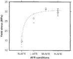
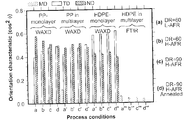
* 다층 필름 성분 뿐만 아니라 PP 및 HDPE 단층 필름에 대해 냉각 공기흐름율(AFR), 연신비(DR) 및 어닐링의 상당한 효과가 관찰되었다. Significant effects of cooling air flow rate (AFR), draw ratio (DR) and annealing have been observed for PP and HDPE single layer films as well as multilayer film components.
* 낮은 AFR에서, HDPE는 꼬인 라멜라 모폴로지를 보이는 반면, 높은 AFR에서는 꼬임형과 납작한 케밥형 사이의 중간형이 발견되었다.At low AFR, HDPE showed a twisted lamellar morphology, whereas at high AFR, an intermediate between twisted and flat kebabs was found.
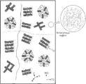
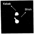
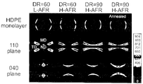
* 다층 필름의 계면에서 PP 내로 침입하는 HDPE 라멜라의 트랜스결정이 관찰되었으며, 수지 결정화 온도의 차이에 기반해 설명되었다.Transcrystals of HDPE lamellae penetrating into the PP at the interface of the multilayer film were observed and explained based on the difference in resin crystallization temperature.
* 높은 냉간연신률에서, HDPE 박막의 기공 크기 및 기공도는 동일 조건하에서 제작된 PP의 것에 비해 훨씬 컸다. 이는 PP에 비해 HDPE 박막의 타이 체인(tie chain)이 더 길기 때문이다.At high cold elongation, the pore size and porosity of HDPE thin films were much larger than those of PP fabricated under the same conditions. This is because the tie chain of HDPE thin films is longer than that of PP.
* 기공질 다층 박막의 계면에서의 뛰어난(good) 접착은 전구체 필름 계면에서 관찰되는 트랜스결정화에 의한 것이다. Good adhesion at the interface of the porous multilayer thin film is due to the transcrystallization observed at the precursor film interface.
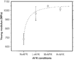
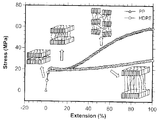
* 전구체 필름에 비해 박막의 경우에서 인장력의 현저한 증가, 계수(modulus)의 극적 감소, 및 MD 방향의 연신률(파단 시 연신률)가 관찰되었다. A significant increase in tensile force, a dramatic decrease in modulus, and elongation in elongation (elongation at break) were observed in the case of thin films compared to precursor films.
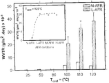
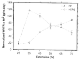
* 콜드 스트레칭 도중에 적용 연신률을 증가시킴에 따라, HDPE의 경우 투습도(WVTR)가 단조로운 상승을 보였으며, 반면, PP의 경우 WVTR이 처음에는 크게 상승하다가 감소했다.Increasing the applied elongation during cold stretching, the WVTR increased monotonically for HDPE, whereas for PP, WVTR initially increased significantly and then decreased.
* 삼층 미세기공 박막의 경우 단일층 박막에 비해 낮은 투과도를 보였으며, 이는 단층 필름에 비해 다층 필름의 PP 및 HDPE 성분의 더 낮은 배향도와 계면에서의 존재 때문인 것으로 간주된다.
* The three-layer microporous thin film showed lower permeability compared to the single layer thin film, which is considered to be due to the lower orientation of the PP and HDPE components of the multilayer film and the presence at the interface compared to the single layer film.
본 개시내용의 다양한 실시예를 나타내는 첨부 도면은 다음과 같다:
도 1은 압연 온도 120, 110, 및 100 ℃에서 본 개시내용의 일 실시예에 따른 캐스트 필름의 DSC 스캔을 나타낸 것으로, 상부 곡선들은 N-AFR(저풍량) 조건하에서 생산된 캐스트 필름의 서모그램인 반면, 하부 곡선들은 연신비(draw ratio, DR)=75 하에서 제조된 필름의 서모그램을 나타내며;
도 2는 각기 상이한 캐스트 압연 온도의 함수로 본 개시내용에 따른 실시예의 결정화 배향 함수를 도시한 그래프로, 삽도에는 Tcast= 120℃; DR=75 조건의 결정화 배향 함수 대 풍량의 곡선을 도시하였고;
도 3은 각기 상이한 캐스트 압연 온도에 대한 본 개시내용에 따른 실시예의 무정형 배향 함수를 도시한 그래프로, 삽도에는 Tcast=120℃; DR=75 조건의 무정형 배향 함수 대 풍량의 곡선을 도시하였고;
도 4는 연신비(DR)가 60, 75, 및 90; Tcast=120℃로 각기 상이한 공기흐름율의 함수로 본 개시내용에 따른 결정 배향 함수의 예를 도시한다;
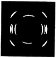
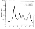
도 5는 각기 상이한 공기 냉각 조건하에서(Tcast=120℃ 및 DR=75) 본 개시내용에 따른 필름의 예의 110 굴절 면의 2θ에서의 2D WAXD 패턴 및 방위각 세기를 도시한다;
도 6은 각기 상이한 공기 냉각 조건하에서 본 개시내용에 따른 필름의 한 실시예의 110 굴절 면의 2θ에서의 2D WAXD 패턴 및 방위각 세기를 도시한다;a) N-AFR, b) L-AFR, 및 c) M-AFR (중간 공기흐름량); Tcast=120℃ 및 DR=75., 도식은 추정 결정 배향을 나타냄;
도 7은 MD, TD, 및 ND 방향의 결정축 (a, b and c)의 cos2 (φ)로의 배향특성을 도시한 것으로, 본 기재내용에 따라 Tcast=120℃ 및 DR=75 실시예이다. 도식은 필름 생성축 및 결정 블록의 좌표;
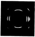
도 8은 각기 다른 공기 흐름 냉각 조건에 대한 본 기재내용에 따른 실시예에서 2D SAXS 패턴 및 자오선 방향의 방위각 세기를 도시한다; Tcast=120℃ 및 DR=75;
도 9는 본 기재내용의 실시예에 따른 Lorentz 보정된 SAXS 세기 프로파일을 도시한 것으로, 다양한 공기 냉각 조건하에서 준비되었다; Tcast=120℃ 및 DR=75;
도 10은 본 기재내용에 따른 표면의 시료에 대한 주사전자현미경 사진을 도시한 것으로, 필름은 다음의 조건으로 제작했다: a) N-AFR 및 Tcast=120℃, b) N-AFR 및 Tcast=110℃, 및 c) L-AFR 및 Tcast=120℃, 우측 영상은 사각형에 대응하는 단면의 확대된 현미경 사진; DR=75, MD ↑ 및 TD →;
도 11은 본 기재내용의 실시예에 따른 일반적인 응력-변형도 거동 곡선을 나타낸 것으로, 상기 필름은 MD(상부 곡선) 및 TD(하부 곡선)을 따라 N-AFR 및 L-AFR 조건하에 제조되었다; Tcast=120℃ 및 DR=75;
도 12A, 12B, 12C, 및 12D는 본 기재내용에 따른 실시예에 있어서, 다양한 공기 유량 조건에서의 MD를 따라 필름의 기계적특성과 관련된 곡선을 나타낸 것으로, 상기 필름은 Tcast=120℃ 및 DR=75 하에서 제조되었다;
도 13은 본 기재내용에 따른 실시예에 있어서, 다양한 공기 유량 조건에서의 TD를 따라 필름의 연신파괴변위(상부 곡선) 및 항복응력(하부 곡선)을 나타낸 것으로, 상기 필름은 Tcast=120℃ 및 DR=75 하에서 제조되었다;
도 14A 및 도 14B는 본 기재내용에 따른 실시예에 있어서, 공냉되지 않은 캐스트필름(14A) 및 공냉된 캐스트 필름(14B) 분자 구조의 제안된 픽토그램을 나타낸 것이고(직선은 MD를 따른 파열 경로(tear path)를 나타내고, 점선은 TD를 따른 파열 경로는 나타낸다);
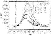
도 15는 본 기재내용에 따른 실시예에 있어서, 다른 용융온도에서의 편중된 완화 스펙트라(weighted relaxation spectra)를 나타낸 것이고(수직 점선은 실험 중 뒤덮힌(covered) 파장의 범위를 나타낸 것이다);
도 16A 및 16B는 본 기재내용에 따른 실시예에 있어서, N-AFR (16A) 및 L-AFR (16B)에서 얻어진 필름 표면의 주사전자현미경 사진을 나타낸 것이고, 상기 필름은 Tcast=120℃ 및 DR=75, 35 % 냉간연신, 55%의 고온연신 조건 하에서 제조되었다; MD ↑ 및 TD →;
도 17은 본 기재내용에 따른 실시예에 있어서, 캐스트 롤 온도의 함수(function)인 투습률(water vapor transmission rate, WVTR)을 나타낸 것으로, 상기 삽도(inset)는 Tcast=120℃ 조건에서의 공기 유량 속도의 함수로써 투습률을 나타낸 것이다;
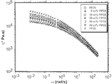
도 18은 본 기재내용에 따른 실시예에 있어서, 각도 주파수(T=190℃)의 함수로써 표현된 복합점도를 나타낸 곡선이고;
도 19는 본 기재내용에 따른 실시예에 있어서, PP08 성분(T=190℃)의 함수로써 표현된, 다른 각도 주파수에서의 복합점도를 나타낸 곡선이고;
도 20은 본 기재내용에 따른 실시예에 있어서, 전체 블렌드에 대한 순수 폴리프로필렌(neat PPs)의 편중된 완화 스펙트라(weighted relaxation spectra) 곡선을 나타낸 것이고; T=190℃(수직 점섬은 실험 중 뒤덮힌 파장의 범위를 나타낸다);
도 21은 본 기재내용에 따른 실시예에 있어서, 전체 블렌드(T=190℃)에 대한 순수 폴리프로필렌의 콜-콜 플롯(Cole-Cole plot)을 나타낸 것이고;
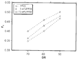
도 22는 본 기재내용에 따른 실시예에 있어서, 전구체 필름의 연신비(draw ratio) 함수로써 결정 배향 함수(FTIR로 부터 얻어진)를 나타낸 것이고;
도 23은 본 기재내용에 따른 실시예에 있어서, 다양한 어닐링 조건에서의 필름의 결정도를 나타낸 것으로, (a) 140℃에서 어닐링, (b) 5% 연신하에서 140℃ 어닐링, 및 (c) 120℃에서 어닐링한 것이며, 상기 어닐링은 DR=70, 35 % 냉간연신, 55%의 고온연신 조건 하에서 30 분 동안 수행되었다;
도 24는 본 기재내용에 따른 실시예에 있어서, PP08 성분의 함수로써 결정질 및 비정질 배향 파라미터를 나타낸 것으로, 상기 어닐링은 140℃에서 30분간 수행되었다(DR=70);
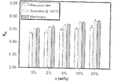
도 25는 본 기재내용에 따른 실시예에 있어서, PP08 성분의 함수로써 전구체 필름, 어닐링된 필름 및 막의 결정도를 나타낸 것으로, 상기 어닐링은 DR=70, 35 % 냉간연신, 55%의 고온연신 조건 하의 140℃ 온도에서 30 분동안 수행되었다;
도 26A, 26B, 26C, 26D, 및 26E는 본 기재내용에 따른 실시예에 있어서, 전구체 필름, 어닐링된 샘플, 막을 위한 10 중량%의 PP08 블렌드의 WAXD 패턴을 나타낸 것으로, MD, TD 및 ND를 따른 결정의 cos2로써의 배향형태, 및 상기 써클(circle)을 통해 통합되는 회절 스펙트럼을 나타낸다: 이때, 상기 어닐링은 DR=70, 35 % 냉간연신, 55%의 고온연신 조건 하의 140℃ 온도에서 30 분동안 수행되었다;
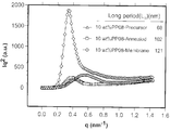
도 27은 전구체 필름, 어닐링된 필름, 및 연신된(stretched) 10중량% PP08 필름의 SAXS 강도 프로파일을 나타낸 것으로, 상기 어닐링은 DR=70, 35 % 냉간연신, 55%의 고온연신 조건 하의 140℃ 온도에서 30 분동안 수행되었다;
도 28A 및 28B는 본 기재내용의 실시예에 있어서, 전구체 필름의 SAXS 패턴을 나타낸 것이고; PP28(28A) 및 10중량% PP08(28B); DR= 70;
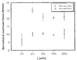
도 29는 본 기재내용의 실시예에 있어서, PP08 성분의 함수로써 피어싱을 위한 정규화된 최대힘(normalized maximum force)을 나타낸 것으로, 상기 어닐링은 DR=70, 변형속도=25 mm/min 조건 하의 140℃ 온도에서 30 분동안 수행되었다;
도 30은 본 기재내용의 실시예에 있어서, PP08성분의 함수로써 MD를 따른 전구체 필름의 연신파괴변위를 나타낸 것이고(DR=70, 변형속도=25 mm/min);
도 31은 본 기재내용의 실시예에 있어서, PP28 및 블렌드의 전구체 필름을 위한 TD를 따른 응력-변형도 곡선을 나타낸 것이고(DR=70, 변형속도=25 mm/min);
도 32A, 32B, 32C 및 32D는 본 기재내용의 실시예에 있어서, 어닐링된 PP28 필름(32A), 10중량% PP08 블렌드 필름(32B)의 WAXD 패턴, 필름 제조 축, 및 결정 블럭 좌표(crystal block coordinates, 32C 및 32D)를 나타낸 것으로, 상기 어닐링은 DR=70 조건 하의 140℃ 온도에서 30 분동안 수행되었다;
도 33A1 , 33A2, 33B1 , 33B2, 33C1 및 33C2는 본 기재내용의 실시예에 있어서, PP28(도 33A1 및 33A2), 5 중량% PP08 블렌드(33B1 및 33B2), 및 10 중량% PP08 블렌드(33C1 및 33C2)로 제조된 미세기공 막의 표면(상부 이미지) 및 단면적(하부 이미지)을 나타낸 주사전자현미경 이미지이고; DR=70, 35 % 냉간연신, 55%의 고온연신;
도 34는 본 기재내용의 실시예에 있어서, 미세기공 PP28, 5 중량% 블렌드 및 10 중량% 블렌드 막의 기공 크기 분포를 나타낸 것이고(DR=70, 35 % 냉간연신, 55%의 고온연신);
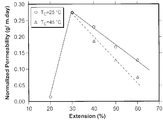
도 35는 본 기재내용의 실시예에 있어서, 25℃ 및 45℃ 온도에서의 냉간연신 동안의 연신률 함수로써, 10 중량% PP08 블렌드 막의 일반화된 투습율을 나타낸 것으로, DR=70, 55%의 고온연신 및 50 mm/min의 연신속도(draw speed)의 조건에서 수행되었으며;
도 36은 본 기재내용의 실시예에 있어서, 120℃ 및 140℃ 온도에서의 고온연신 동안의 연신률 함수로써, 10 중량% PP08 블렌드 막의 일반화된 투습율을 나타낸 것으로, DR=70, 35%의 냉간연신 및 50 mm/min의 연신속도(draw speed)의 조건에서 수행되었으며;
도 37은 본 기재내용의 실시예에 있어서, 각도 주파수(T=190℃)의 함수로써 복합점도를 나타낸 것으로, 상기 삽도는 수지(resins)의 편중된 완화 스펙트라(weighted relaxation spectra) 곡선을 나타낸 것이며(수직 점선은 실험 중 뒤덮힌 파장의 범위를 나타낸다);
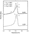
도 38은 본 기재내용의 실시예에 있어서, 다층 필름 중 단층의 DSC 가열 써모그램(thermograms)을 나타낸 것이고(DR=90 및 H-AFR);
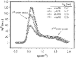
도 39는 본 기재내용의 실시예에 있어서, PP 및 HDPE 단층 필름의 일반화된 2D WAXD 패턴 및 써클을 통해 결합된 회절 스펙트럼을 나타낸 것이고(DR=90 및 H-AFR);
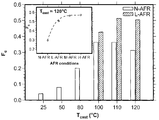
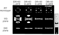
도 4OA, 4OB 및 40C는 본 기재내용의 실시예에 있어서, 각각 다른 DR, AFR 및 어닐링 조건 하에서 얻어진 필름의 2D WAXD 패턴 및 극점도를 나타낸 것으로, PP 단층필름(40A), 다층구조 중의 PP(40B), 및 HDPE 단층필름(40C)이고, 상기 어닐링은 120℃에서 30 분간 수행되었다;
도 41 A, 41B 및 41C는 본 기재내용의 실시예에 있어서, 각각 다른 DR, AFR 및 어닐링 조건 하에서 얻어진 필름의 MD, TD 및 ND를 따르는 결정축(a,b 및 c)의 cos2 (φ)로써 배향 특성을 나타낸 것이고(c-축 (41A), a-축 (41B), 및 b-axis (41C)), 상기 어닐링은 120℃에서 30 분간 수행되었다;
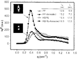
도 42는 본 기재내용의 실시예에 있어서, 전구체, 어닐링된 PP 및 HDPE 필름의 Lorentz 보정된 SAXS 강도 프로파일을 나타낸 것으로, 상기 어닐링은 DR=90 및 H-AFR 조건 하에의 120℃에서 30 분간 수행되었다;
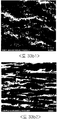
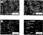
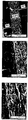
도 43은 본 기재내용의 실시예에 있어서, 식각된 전구체 필름의 표면을 나타낸 주사전자현미경 사진으로, (a) PP 및 (b) HDPE이고, 오른쪽 이미지는 왼쪽 이미지의 고배율 사진이다; DR=90 및 H-AFR, MD ↑ and TD →;
도 44는 본 기재내용의 실시예에 있어서, 다른 배율에서의 식각된 PP/HDPE 다층필름의 계면 모폴로지를 나타낸 것이고; DR=90 및 H-AFR, MD ↑ and TD →;
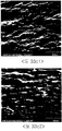
도 45는 본 기재내용의 실시예에 있어서, 미세기공 막(20 μm 두께)의 표면을 나타낸 주사전자현미경 사진이고: (a) PP 및 (b) HDPE; DR=90, H-AFR, 55%의 냉간연신, 이어서 75%의 고온연신, MD ↑ 및 TD →;
도 46은 본 기재내용의 실시예에 있어서, 다른 배율에서의 3층 미세기공 막(20 μm 두께)의 단면을 나타낸 주사전자현미경 사진이고; DR=90, H-AFR, 55%의 냉간연신, 이어서 75%의 고온연신;
도 47은 본 기재내용의 실시예에 있어서, 25℃, DR=90, H-AFR, 75% 고온연신 조건의 냉간연신 동안의 연신률의 함수로써 PP 및 HDPE 막의 일반화된 투습율을 나타낸 것이고;
도 48은 본 기재내용의 실시예에 있어서, 냉간연신 단계 중, 어닐링된 PP 및 HDPE의 응력-변형 거동을 나타낸 것으로, 상기 어닐링은 DR=90, H-AFR 조건인 120℃온도에서 30 분간 수행되었다;
도 49는 본 기재내용의 실시예에 있어서, BET에 의해 측정된 PP 및 HDPE 막의 질소흡착등온선(nitrogen adsorption isotherms)을 나타낸 것이고(DR=90, H-AFR, 35%의 냉간연신, 이어서 75%의 고온연신);
도 50은 본 기재내용의 실시예에 있어서, 다층 미세기공막의 단면을 나타낸 주사전자현미경 사진이고; DR=90, H-AFR, 55%의 냉간연신, 이어서 175%의 고온연신(화살표는 라멜라로의 HDPE 층간 미세피브릴(interlamellar microfibrils)연결을 나타낸다);
도 51은 본 기재내용에 따른 방법 실시예를 수행하기 위해 사용된 장치를 도식적으로 나타낸 것으로, 상기 다이 출구와 닙롤(nip roll) 사이의 거리를 나타내고, 상기 델타 x는 압출기(extruder) 및 캐스트 롤(냉각 드럼) 사이의 온도차이(Td-Tc)와 Tcast를 나타내며, 상기 Ua 및 Ta는 가스냉각소도 및 가스의 온도를 나타낸다;The accompanying drawings, which illustrate various embodiments of the present disclosure, are as follows:
1 shows a DSC scan of a cast film according to one embodiment of the present disclosure at rolling
FIG. 2 is a graph depicting the crystallization orientation function of an embodiment according to the present disclosure as a function of different cast rolling temperatures, inset in which T cast = 120 ° C .; Curve of crystallization orientation function vs. air volume under DR = 75 condition is shown;
3 is a graph depicting the amorphous orientation function of an embodiment according to the present disclosure for different cast rolling temperatures, with inset T cast = 120 ° C; Curves for the amorphous orientation function vs. air flow at DR = 75 conditions are shown;
4 shows draw ratios DR of 60, 75, and 90; An example of the crystallographic orientation function according to the present disclosure is shown as a function of different air flow rates with T cast = 120 ° C .;
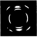
5 shows the 2D WAXD pattern and azimuth intensity at 2θ of the 110 refracting surface of an example of a film according to the present disclosure under different air cooling conditions (T cast = 120 ° C. and DR = 75);
6 shows the 2D WAXD pattern and azimuth intensity at 2θ of the 110 refractive surface of one embodiment of a film according to the present disclosure under different air cooling conditions; a) N-AFR, b) L-AFR, and c ) M-AFR (medium airflow); T cast = 120 ° C. and DR = 75. The scheme shows an estimated crystal orientation;
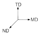
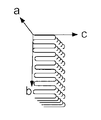
FIG. 7 illustrates the orientation characteristics of crystal axes (a, b and c) in cos 2 (φ) in the MD, TD, and ND directions, in which T cast = 120 ° C. and DR = 75 examples according to the present disclosure. . The schematic is the film generation axis and the coordinates of the crystal block;
8 shows the 2D SAXS pattern and azimuth intensity in the meridian direction in an embodiment according to the present disclosure for different air flow cooling conditions; T cast = 120 ° C and DR = 75;
9 illustrates Lorentz calibrated SAXS intensity profiles according to embodiments of the present disclosure, which were prepared under various air cooling conditions; T cast = 120 ° C and DR = 75;
Figure 10 shows a scanning electron micrograph of a sample of the surface according to the present disclosure, the film was made under the following conditions: a) N-AFR and T cast = 120 ℃, b) N-AFR and T cast = 110 ° C, and c) L-AFR and T cast = 120 ° C, the right image is an enlarged micrograph of the cross section corresponding to the square; DR = 75, MD ↑ and TD →;
FIG. 11 shows a general stress-strain behavior curve according to an embodiment of the present disclosure, wherein the film was prepared under N-AFR and L-AFR conditions along MD (top curve) and TD (bottom curve); T cast = 120 ° C and DR = 75;
12A, 12B, 12C, and 12D show curves related to the mechanical properties of a film along MD in various air flow conditions, in an embodiment according to the present disclosure, wherein the film is T cast = 120 ° C. and DR Prepared under = 75;
FIG. 13 shows stretch fracture displacement (top curve) and yield stress (bottom curve) of a film along TD at various air flow conditions in an embodiment according to the present disclosure, wherein the film is T cast = 120 ° C. FIG. And under DR = 75;
14A and 14B show proposed pictograms of the molecular structures of the uncooled cast film 14A and the air-cooled cast film 14B in an embodiment according to the present disclosure (straight lines indicate bursting paths along MD) tear path), and the dotted line indicates the tear path along the TD);
FIG. 15 shows a weighted relaxation spectra at different melting temperatures, in an embodiment according to the present disclosure (vertical dotted lines represent the range of covered wavelengths during the experiment); FIG.
16A and 16B show scanning electron micrographs of the surface of films obtained in N-AFR (16A) and L-AFR (16B) in Examples according to the present disclosure, wherein the film is T cast = 120 ° C. and DR = 75, 35% cold draw, 55% hot draw conditions; MD ↑ and TD →;
FIG. 17 illustrates a water vapor transmission rate (WVTR) as a function of cast roll temperature in an embodiment in accordance with the present disclosure, wherein the inset is at T cast = 120 ° C. FIG. Moisture permeability as a function of air flow rate;
18 is a curve showing a composite viscosity expressed as a function of angular frequency (T = 190 ° C.) in an embodiment according to the present disclosure;
19 is a curve showing composite viscosity at different angular frequencies, expressed as a function of PP08 component (T = 190 ° C.), in an embodiment according to the present disclosure;
FIG. 20 shows a weighted relaxation spectra curve of pure polypropylene (neat PPs) for the entire blend in an embodiment according to the present disclosure; FIG. T = 190 ° C. (vertical dot islands represent a range of covered wavelengths during the experiment);
FIG. 21 shows a Cole-Cole plot of pure polypropylene over the entire blend (T = 190 ° C.) in an embodiment according to the present disclosure; FIG.
FIG. 22 illustrates a crystal orientation function (obtained from FTIR) as a draw ratio function of a precursor film, in an embodiment according to the present disclosure; FIG.
FIG. 23 shows crystallinity of films under various annealing conditions in Examples according to the present disclosure, (a) annealing at 140 ° C., (b) 140 ° C. annealing under 5% elongation, and (c) 120 ° C. FIG. Annealed at, the annealing was carried out for 30 minutes under DR = 70, 35% cold drawn, 55% hot drawn conditions;
24 shows crystalline and amorphous orientation parameters as a function of PP08 component, in an embodiment according to the present disclosure, wherein the annealing was performed at 140 ° C. for 30 minutes (DR = 70);
FIG. 25 shows crystallinity of precursor films, annealed films and films as a function of PP08 component in an embodiment according to the present disclosure, wherein the annealing is performed under DR = 70, 35% cold drawing, 55% hot drawing conditions. 30 minutes at 140 ° C. temperature;
26A, 26B, 26C, 26D, and 26E show WAXD patterns of 10% by weight PP08 blends for precursor films, annealed samples, and films in the examples according to the present disclosure, showing MD, TD, and ND. The orientation of the crystals as cos 2 , and the diffraction spectrum integrated through the circle: wherein the annealing is at a temperature of 140 ° C. under DR = 70, 35% cold drawing, 55% hot drawing conditions. Carried out for 30 minutes;
FIG. 27 shows SAXS strength profiles of precursor films, annealed films, and stretched 10 wt.% PP08 films, with annealing at 140 ° C. under DR = 70, 35% cold drawn, 55% hot drawn conditions. 30 minutes at temperature;
28A and 28B show SAXS patterns of precursor films, in the examples of the present disclosure; PP28 (28A) and 10% by weight PP08 (28B); DR = 70;
FIG. 29 shows a normalized maximum force for piercing as a function of PP08 component, in an embodiment of the present disclosure, wherein the annealing is at 140 with DR = 70 and strain rate = 25 mm / min. At 30 ° C. for 30 minutes;
FIG. 30 shows the stretch fracture displacement of a precursor film along MD as a function of PP08 component in an embodiment of the present disclosure (DR = 70, strain rate = 25 mm / min); FIG.
FIG. 31 shows stress-strain curves along TD for precursor films of PP28 and blends (DR = 70, strain rate = 25 mm / min) in an embodiment of the present disclosure;
32A, 32B, 32C, and 32D illustrate WAXD patterns, film manufacturing axes, and crystal block coordinates of annealed
33A1, 33A2, 33B1, 33B2, 33C1 and 33C2 are PP28 (FIGS. 33A1 and 33A2), 5 wt% PP08 blends (33B1 and 33B2), and 10 wt% PP08 blends (33C1 and A scanning electron microscope image showing the surface (top image) and cross-sectional area (bottom image) of the microporous membrane prepared with 33C2); DR = 70, 35% cold draw, 55% hot draw;
34 shows pore size distributions of microporous PP28, 5 wt% blend and 10 wt% blend membranes (DR = 70, 35% cold stretching, 55% hot stretching) in the examples of the present disclosure;
FIG. 35 shows the generalized moisture vapor transmission rate of a 10 wt% PP08 blend membrane as a function of elongation during cold stretching at 25 ° C. and 45 ° C. temperature in an embodiment of the present disclosure, with DR = 70, 55% high temperature. Carried out under conditions of drawing and draw speed of 50 mm / min;
FIG. 36 shows a generalized moisture vapor transmission rate of a 10 wt% PP08 blend membrane as a function of elongation during hot stretching at 120 ° C. and 140 ° C. temperature in an embodiment of the present disclosure, with DR = 70, 35% cold Carried out under conditions of drawing and draw speed of 50 mm / min;
FIG. 37 shows a composite viscosity as a function of angular frequency (T = 190 ° C.), in an embodiment of the present disclosure, wherein the inset shows a weighted relaxation spectra curve of resins. (Vertical dotted lines indicate the range of wavelengths covered during the experiment);
FIG. 38 shows DSC heating thermograms of monolayers in a multilayer film in the examples of the present disclosure (DR = 90 and H-AFR); FIG.
FIG. 39 shows diffraction spectra coupled through a generalized 2D WAXD pattern and circle of PP and HDPE monolayer films in an embodiment of the present disclosure (DR = 90 and H-AFR); FIG.
4OA, 4OB, and 40C show 2D WAXD patterns and pole figures of films obtained under different DR, AFR, and annealing conditions, respectively, in the examples of the present disclosure; PP monolayer film 40A, PP in a multilayer structure ( 40B), and HDPE monolayer film 40C, wherein the annealing was performed at 120 ° C. for 30 minutes;
41A, 41B and 41C show cos 2 (φ) of crystal axes (a, b and c) along MD, TD and ND of films obtained under different DR, AFR and annealing conditions, respectively, in the examples of the present disclosure. Orientation characteristics (c-axis (41A), a-axis (41B), and b-axis (41C)), the annealing was performed at 120 ° C. for 30 minutes;
FIG. 42 shows Lorentz calibrated SAXS intensity profiles of precursor, annealed PP and HDPE films in an embodiment of the present disclosure, wherein the annealing was performed for 30 minutes at 120 ° C. under DR = 90 and H-AFR conditions. Became;
FIG. 43 is a scanning electron micrograph showing the surface of an etched precursor film in an embodiment of the present disclosure, (a) PP and (b) HDPE, and the right image is a high magnification photograph of the left image; DR = 90 and H-AFR, MD ↑ and TD →;
FIG. 44 illustrates interfacial morphologies of etched PP / HDPE multilayer films at different magnifications, in embodiments of the present disclosure; FIG. DR = 90 and H-AFR, MD ↑ and TD →;
45 is a scanning electron micrograph showing the surface of a microporous membrane (20 μm thick) in an embodiment of the present disclosure: (a) PP and (b) HDPE; DR = 90, H-AFR, 55% cold draw followed by 75% hot draw, MD ↑ and TD →;
46 is a scanning electron micrograph showing a cross section of a three layer microporous membrane (20 μm thick) at different magnifications in an embodiment of the present disclosure; DR = 90, H-AFR, 55% cold draw followed by 75% hot draw;
FIG. 47 shows the generalized moisture vapor transmission rate of PP and HDPE membranes as a function of elongation during cold drawing at 25 ° C., DR = 90, H-AFR, 75% hot drawing conditions, in an embodiment of the present disclosure; FIG.
FIG. 48 shows stress-strain behavior of annealed PP and HDPE during the cold drawing step in an embodiment of the present disclosure, wherein the annealing is performed at 120 ° C. with DR = 90 and H-AFR conditions for 30 minutes. Became;
FIG. 49 shows nitrogen adsorption isotherms of PP and HDPE membranes as measured by BET in the examples of the present disclosure (DR = 90, H-AFR, 35% cold draw, followed by 75% High temperature stretching);
50 is a scanning electron micrograph showing a cross section of a multilayer microporous membrane, in an embodiment of the present disclosure; DR = 90, H-AFR, 55% cold draw followed by 175% hot draw (arrow indicates HDPE interlamellar microfibrils connectivity to lamellar);
FIG. 51 is a schematic representation of an apparatus used to perform a method embodiment according to the present disclosure, showing the distance between the die outlet and a nip roll, wherein the delta x represents an extruder and a cast roll. Temperature difference (Td-Tc) between the (cooling drum) and T cast , wherein Ua and Ta represent gas cooling degree and temperature of gas;
다음에 제시되는 실시예들은 한정적인 예가 아니다.The embodiments presented below are not limitative examples.
상기 기술한 방법의 경우, 필름의 냉각에 사용되는 가스는 공기일 수 있다. 또한 질소, 아르곤, 헬륨 등과 같이 상용화되어 있는 기타 다양한 가스일 수 있다. In the case of the above-described method, the gas used for cooling the film may be air. It can also be various other gases that are commercially available such as nitrogen, argon, helium, and the like.
예를 들어, 상기 캐스트 필름은 적어도 50, 55, 60, 65, 70, 75, 또는 80의 연신비(DR)로 필름을 유출함에 따라 제조될 수 있다. 예를 들어, 상기 연신비는 약 50 내지 약 100, 또는 약 60 내지 약 90일 수 있다. For example, the cast film can be prepared by bleeding the film at a draw ratio DR of at least 50, 55, 60, 65, 70, 75, or 80. For example, the draw ratio may be about 50 to about 100, or about 60 to about 90.
예를 들어, 상기 필름은 약 20μm 내지 약 60 μm, 약 30μm 내지 약 50 μm, 또는 약 32μm 내지 약 45 μm의 두께를 가질 수 있다. For example, the film may have a thickness of about 20 μm to about 60 μm, about 30 μm to about 50 μm, or about 32 μm to about 45 μm.
일 실시예에 따르면, 상기 가스는 적어도 하나의 에어 나이프(air knife)에 의해 상기 필름 상으로 블로잉 될 수 있다. According to one embodiment, the gas may be blown onto the film by at least one air knife.
예를 들면, 상기 캐스트 필름은 단일층 필름 또는 다층 필름(예를 들면, 2 내지 10층, 2 내지 7층, 2 내지 5층, 2 내지 4층, 2층 또는 3층)일 수 있다.For example, the cast film may be a single layer film or a multilayer film (eg, 2 to 10 layers, 2 to 7 layers, 2 to 5 layers, 2 to 4 layers, 2 layers, or 3 layers).
예를 들면, 상기 가스 냉각 속도는 적어도 압출물의 유동 속도에 따라 0.5, 0.6, 0.7, 0.8, 0.9, 1.0, 1.2, 1.5, 2.0, 3.0, 3.5, 4.0, 4.5, 5.0, 5.5, 6.0, 6.5, 7.0, 7.5, 8.0, 8.5, 또는 kg/hr 당 10 cm3/s일 수 있다. For example, the gas cooling rate may be 0.5, 0.6, 0.7, 0.8, 0.9, 1.0, 1.2, 1.5, 2.0, 3.0, 3.5, 4.0, 4.5, 5.0, 5.5, 6.0, 6.5, at least depending on the flow rate of the extrudate. 7.0, 7.5, 8.0, 8.5, or 10 cm 3 / s per kg / hr.
예를 들면, 상기 가스 냉각 속도는 상기 압출물 유동 속도의 제곱에 대해 적어도 비례적이거나, 또는 압출 필름 폭의 역수에 대해 비례적일 수 있다. For example, the gas cooling rate may be at least proportional to the square of the extrudate flow rate or may be proportional to the inverse of the extrusion film width.
일 실시예에 따르면, 상기 필름은 다이에 의해 압출되고, 적어도 하나의 냉각 드럼 상에서 압연될 수 있다. According to one embodiment, the film may be extruded by a die and rolled on at least one cooling drum.
예를 들면, 상기 적어도 하나의 냉각 드럼의 온도는 약 20℃ 내지 약 150℃, 약 40℃ 내지 약 140℃, 약 50℃ 내지 약 14O℃, 약 75℃ 내지 약 140℃, 약 80℃ 내지 약 13O℃, 약 85℃ 내지 약 115℃, 약 90℃ 내지 약 12O℃, 또는 약 100℃ 내지 약 110℃일 수 있다. For example, the temperature of the at least one cooling drum may range from about 20 ° C to about 150 ° C, from about 40 ° C to about 140 ° C, from about 50 ° C to about 140 ° C, from about 75 ° C to about 140 ° C, from about 80 ° C to about 13 ° C., about 85 ° C. to about 115 ° C., about 90 ° C. to about 120 ° C., or about 100 ° C. to about 110 ° C.
예를 들면, 상기 필름은 폴리프로필렌, 폴리에틸렌 또는 그 혼합물을 포함할 수 있다.For example, the film may comprise polypropylene, polyethylene or mixtures thereof.
예를 들면, 상기 필름은 선형 폴리프로필렌, 고밀도 폴리에틸렌 또는 그 혼합물을 포함할 수 있다. For example, the film may comprise linear polypropylene, high density polyethylene or mixtures thereof.
예를 들면, 사기 필름은 라멜라 결정 구조를 가질 수 있다. 예를 들면, 상기 필름은 적어도 40, 50, 60, 70, 80 또는 90%의 결정도를 가질 수 있다. For example, the frying film may have a lamellar crystal structure. For example, the film can have a crystallinity of at least 40, 50, 60, 70, 80 or 90%.
상기 설명한 방법에 따라 제조된 캐스트 필름을 사용하여 미세기공 박막을 제조할 때, 상기 필름은 용융 온도 이하의 온도에서 어닐링 될 수 있다. 예를 들면, 상기 필름은 또한 약 100℃ 내지 약 15O℃, 약 110℃ 내지 약 140℃, 또는 약 120℃ 내지 약 14O℃에서 어닐링 될 수 있다. 예를 들면, 상기 필름은 제1 온도에서 연신 될 수 있으며, 상기 필름은 제2 온도에서 연신 될 수 있다. 예를 들면, 상기 제1 온도는 약 10℃ 내지 약 50℃, 약 15℃ 내지 약 40℃, 또는 20℃ 내지 약 30℃ 일 수 있다. 예를 들면, 상기 제2 온도는 약 90℃ 내지 약 150 ℃, 약 100℃ 내지 약 140 ℃, 또는 약 110℃ 내지 약 130 ℃ 일 수 있다.When preparing the microporous thin film using the cast film prepared according to the above-described method, the film may be annealed at a temperature below the melting temperature. For example, the film may also be annealed at about 100 ° C. to about 150 ° C., about 110 ° C. to about 140 ° C., or about 120 ° C. to about 140 ° C. For example, the film may be drawn at a first temperature and the film may be drawn at a second temperature. For example, the first temperature may be about 10 ° C to about 50 ° C, about 15 ° C to about 40 ° C, or 20 ° C to about 30 ° C. For example, the second temperature may be about 90 ° C to about 150 ° C, about 100 ° C to about 140 ° C, or about 110 ° C to about 130 ° C.
예를 들면, 상기 필름은 상기 제1 온도에서 약 20 % 내지 약 75 % 연신 될 수 있으며, 상기 필름은 상기 제2 온도에서 약 40 내지 약 200 % 로 연신 될 수 있다.For example, the film may be stretched from about 20% to about 75% at the first temperature, and the film may be stretched from about 40 to about 200% at the second temperature.
예를 들면, 상기 필름은 상기 제1 온도에서 약 30 % 내지 약 70 % 로 연신 될 수 있으며, 상기 필름은 상기 제2 온도에서 약 50 내지 약 175 % 로 연신 될 수 있다.For example, the film may be stretched from about 30% to about 70% at the first temperature, and the film may be stretched from about 50 to about 175% at the second temperature.
예를 들면, 상기 필름은 상기 제1 온도에서 약 30 % 내지 약 40 % 로 연신 될 수 있으며, 상기 필름은 상기 제2 온도에서 약 50 내지 약 60 % 로 연신 될 수 있다.For example, the film may be stretched from about 30% to about 40% at the first temperature, and the film may be stretched from about 50 to about 60% at the second temperature.
예를 들면, 상기 필름은 상기 제1 온도에서 약 50 % 내지 약 60 % 로 연신 될 수 있으며, 상기 필름은 상기 제2 온도에서 약 70 내지 약 80 % 로 연신 될 수 있다.For example, the film may be stretched from about 50% to about 60% at the first temperature, and the film may be stretched from about 70 to about 80% at the second temperature.
상기의 방법에 기재된 방식으로 상기 캐스트 필름의 모폴로지를 제어함에 따라 제조된 적어도 두 개의 캐스트 필름을 포함하는 다층 미세기공 박막을 제조함에 있어, 상기 적어도 두 개의 캐스트 필름은 어닐링 및 연신 처리될 수 있다. 예를 들면, 상기 적어도 두 개의 캐스트 필름은 각각의 필름의 용융온도 이하의 온도에서 어닐링 처리될 수 있다. 예를 들면, 상기 적어도 두 개의 캐스트 필름은 약 100℃ 내지 약 130℃, 약 110℃ 내지 약 130℃, 또는 약 120℃ 내지 약 13O℃에서 어닐링 처리될 수 있다.In producing a multilayer microporous thin film comprising at least two cast films prepared by controlling the morphology of the cast film in the manner described in the above method, the at least two cast films may be annealed and stretched. For example, the at least two cast films may be annealed at temperatures below the melting temperature of each film. For example, the at least two cast films may be annealed at about 100 ° C. to about 130 ° C., about 110 ° C. to about 130 ° C., or about 120 ° C. to about 130 ° C.
예를 들면, 상기 적어도 두 개의 필름은 제1 온도에서 연신 처리되고, 그런 다음 상기 적어도 두 개의 필름은 제2 온도에서 연신 처리될 수 있다. 예를 들면, 상기 제1 온도는 약 10℃ 내지 약 50 ℃, 약 15℃ 내지 약 40 ℃, 또는 약 20℃ 내지 약 30 ℃ 일 수 있다. 예를 들면, 상기 제2 온도는 약 90℃ 내지 약 13O℃, 약 100℃ 내지 약 130℃, 또는 약 110℃ 내지 약 13O℃ 일 수 있다. For example, the at least two films can be drawn at a first temperature, and then the at least two films can be drawn at a second temperature. For example, the first temperature may be about 10 ° C to about 50 ° C, about 15 ° C to about 40 ° C, or about 20 ° C to about 30 ° C. For example, the second temperature may be about 90 ° C to about 1300 ° C, about 100 ° C to about 130 ° C, or about 110 ° C to about 1300 ° C.
예를 들면, 상기 적어도 두 개의 필름은 상기 제1 온도에서 약 20 % 내지 약 75 % 로 연신 처리될 수 있으며, 상기 적어도 두 개의 필름은 상기 제2 온도에서 약 40 내지 약 200 % 로 연신 처리될 수 있다.For example, the at least two films may be stretched from about 20% to about 75% at the first temperature, and the at least two films may be stretched from about 40 to about 200% at the second temperature. Can be.
예를 들면, 상기 적어도 두 개의 필름은 상기 제1 온도에서 약 30 % 내지 약 70 % 로 연신 처리될 수 있으며, 상기 적어도 두 개의 필름은 상기 제2 온도에서 약 50 내지 약 175 % 로 연신 처리될 수 있다.For example, the at least two films may be stretched from about 30% to about 70% at the first temperature, and the at least two films may be stretched from about 50 to about 175% at the second temperature. Can be.
예를 들면, 상기 적어도 두 개의 필름은 상기 제1 온도에서 약 30 % 내지 약 40 % 로 연신 처리될 수 있으며, 상기 적어도 두 개의 필름은 상기 제2 온도에서 약 50 내지 약 60 % 로 연신 처리될 수 있다.For example, the at least two films can be stretched from about 30% to about 40% at the first temperature, and the at least two films are stretched from about 50 to about 60% at the second temperature. Can be.
예를 들면, 상기 적어도 두 개의 필름은 상기 제1 온도에서 약 50 % 내지 약 60 % 로 연신 처리될 수 있으며, 상기 적어도 두 개의 필름은 상기 제2 온도에서 약 70 내지 약 80 % 로 연신 처리될 수 있다. For example, the at least two films may be stretched from about 50% to about 60% at the first temperature, and the at least two films may be stretched from about 70 to about 80% at the second temperature. Can be.
예를 들면, 상기 다층 박막은 세 개의 필름을 포함할 수 있으며, 여기서 상기 다층 박막은 제1 선형 폴리프로필렌층, 고밀도 폴리에틸렌층, 및 제2 선형 폴리프로필렌층을 기재 순으로 포함할 수 있다.
For example, the multilayer thin film may include three films, wherein the multilayer thin film may include a first linear polypropylene layer, a high density polyethylene layer, and a second linear polypropylene layer in the order of description.
1- 폴리프로필렌 캐스트 필름의 결정 Crystallization of 1-polypropylene cast film 배향성Orientation , , 모폴로지Morphology 및 기계적 성질에 대한 처리의 효과 및 미세기공 박막의 형성 And the effect of treatment on the mechanical properties and formation of microporous thin films
실험 재료Experimental material
ExxonMobil Company에 의해 공급되는 상용 선형 폴리프로필렌(PP5341)이 선택되었다. MFR(용융흐름속도) 값이 0.8 g/10 min (230℃ 및 2.16 kg의 ASTM 조건)에 이른다. 분자 무게는 영(0)-전단 속도 및 분자량 사이의 상관관계에 기준을 두어 예상했고(선행문헌 10), 대략 772 kg/mol 인 것으로 나타났다. 상기 수지는 140℃ 에서 GPC (Viscotek model 350)을 이용하여 측정한 결과, 2.7 PDI(다분산지수) 및 용매로 1 ,2,4-트라이클로로벤젠(TCB)을 나타냈다. 용융점(Tm) 및 결정화 온도(TC)는 시차주사열량법으로 10 ℃/min 속도로 측정한 결과 각각 161℃ 및 118℃ 이었다.
A commercial linear polypropylene (PP5341) supplied by ExxonMobil Company was chosen. MFR (melt flow rate) values reach 0.8 g / 10 min (230 ° C. and 2.16 kg ASTM conditions). Molecular weights were expected based on the correlation between zero-shear rate and molecular weight (Prior 10) and were found to be approximately 772 kg / mol. The resin was measured using GPC (Viscotek model 350) at 140 ℃, it showed 2.7 PDI (polydispersity index) and 1,2,4-trichlorobenzene (TCB) as a solvent. Melting point (T m ) and crystallization temperature (T C ) were 161 ° C. and 118 ° C., respectively, measured at a rate of 10 ° C./min by differential scanning calorimetry.
필름 및 박막의 제조Production of Films and Thin Films
두께 2.8 mm 및 폭이 122 cm 인 슬릿 다이 및 두 개의 냉각 드럼을 구비한 Davis Standard(Pawcatuk, CT)사의 공업용 다층 캐스트 필름을 이용하여 캐스트 필름을 제조하였다. 220℃ 에서 압출이 수행되었으며, 다이 출구와 닙 롤(nip roll) 사이의 간격은 15 cm 이었다. 상기 다이의 온도는 220℃ 에 설정되었으며, 연신비는 60, 75, 및 90이 적용되었다. 3 mm 개구부 및 130 cm 폭의 치수를 가지는 에어 나이프가 바로 다이의 출구에서 필름 표면에 공기를 제공하도록 다이에 근접하게 설치되었다. 해당 변수로는 냉각 롤(chill roll) 온도, 공기 흐름량, 및 연신비였다. 상기 필름은 120, 110, 100, 80, 50, 및 25℃ 의 냉각 롤(chill roll) 온도하에서 생산되었다. 모든 캐스트 압연 온도에 대해 사용된 공기 냉각비는 0, 1.2, 7.0, 및 12 L/s 였다. 이들 공기 냉각 조건들은 다음의 특징을 각각 갖는다: 공기유량 없음(no air flow rate, N-AFR), 낮은 공기유량(low air flow rate, L-AFR), 중간의 공기유량(medium air flow rate, M-AFR), 및 높은 공기유량(high air flow rate, H-AFR).Cast films were prepared using an industrial multilayer cast film from Davis Standard (Pawcatuk, CT) with a slit die 2.8 mm thick and 122 cm wide and two cooling drums. Extrusion was performed at 220 ° C., with a gap of 15 cm between the die outlet and the nip roll. The die temperature was set at 220 ° C. and draw ratios of 60, 75, and 90 were applied. An air knife having a 3 mm opening and a dimension of 130 cm wide was installed close to the die to provide air to the film surface right at the exit of the die. The variables were chill roll temperature, air flow rate, and draw ratio. The film was produced under chill roll temperatures of 120, 110, 100, 80, 50, and 25 ° C. The air cooling ratios used for all cast rolling temperatures were 0, 1.2, 7.0, and 12 L / s. These air cooling conditions have the following characteristics, respectively: no air flow rate (N-AFR), low air flow rate (L-AFR), medium air flow rate, M-AFR), and high air flow rate (H-AFR).
박막 제조를 위해, 두께, 폭 및 길이가 각각 35 μm, 46, 및 64 mm에 이르는 전구체 필름이 사용되었다. 상기 필름들은 우선 140℃ 에서 30 분간 제1 어닐링 처리되었으며, 25℃ 및 120℃ 에서 각각 콜드 및 핫 스트레칭 처리되었다. 어닐링 및 연신 처리는 둘 다 환경실이 구비된 Instron 기계를 이용하여 수행되었다. 냉간연신 및 고온연신 단계 중에 50 mm/min 의 인장 속도가 적용되었다. 상기 미세기공 박막 제조에 대한 상세사항은 달리 참조할 수 있을 것이다(선행문헌 9).
For thin film production, precursor films with thicknesses, widths, and lengths of up to 35 μm, 46, and 64 mm were used, respectively. The films were first first annealed at 140 ° C. for 30 minutes and then cold and hot stretched at 25 ° C. and 120 ° C., respectively. Both annealing and stretching treatments were performed using an Instron machine equipped with an environment room. Tensile velocities of 50 mm / min were applied during the cold drawing and hot drawing steps. Details of the microporous thin film may be referred to otherwise (prior document 9).
필름 및 박막의 제조Production of Films and Thin Films
FTIR ( Fourier transform infrared spectroscopy ): FTIR ( Fourier transform infrared spectroscopy ) :
FTIR 측정을 위해, Thermo Electron Corp. 사의 Nicolet Magna 860 FTIR 설비(DTGS 검출기, 해상도 2 cm-1, 128 스캔 축적)가 사용되었다. Thermo Electron Corp 사의 Spectra-Tech 셀렌화 아연 선 격자 편광기를 이용하여 빛을 편광했다. 분자 내 나타나는 원자군의 진도 모드에 대응하는 특정 주파수에서 적외선광의 흡수에 따라 측정이 이루어졌다. 또한, 특정 진동이 특정 상(phase)에 기인할 경우, 그 상 내의 배향도를 판단할 수 있다(선행문헌 11). 필름이 배향될 경우, 두 개의 직교 방향, 즉 상세하게는 기준 축(MD)에 대해 평행이자 직교방향인 두 직교 방향의 진동에 의해 면-편광 방사광의 흡수가 상이하게 이루어져야 한다. 이들 두 개의 흡수 값은 다음의 이색비(dichroic ratio, D)로 정의된다(선행문헌 11):
For FTIR measurements, Thermo Electron Corp. Nicolet Magna 860 FTIR equipment (DTGS detector,

여기서, ![]()
![]()
here, ![]()
![]()

폴리프로필렌의 경우, 998 cm-1 파수에서의 흡수는 결정 상(c-축)에 기인하는 반면, 972 cm-1 파수에서의 흡수는 결정 및 비결정 상 둘 다의 기여에 의한 것이다. 전자의 흡수의 경우, 결정 상의 배향도(fc)를 판단할 수 있는 반면, 후자의 흡수의 경우, 평균 배향 함수(fav)가 얻어진다. 비결정 상의 배향도(fam)는 다음에 따라 계산될 수 있다:
For polypropylene, the absorption at 998 cm -1 wavenumber is due to the crystalline phase (c-axis), while the absorption at 972 cm -1 wavenumber is due to the contribution of both the crystalline and amorphous phases. In the case of the absorption of the former, the orientation degree f c of the crystal phase can be judged, whereas in the case of the latter absorption, the average orientation function f av is obtained. The degree of orientation f am of the amorphous phase can be calculated as follows:

여기서, Xc 는 결정화의 정도를 나타낸다. FTIR를 이용하여, 전체, 결정 및 비결정 배향도를 판단할 수 있다.Here, X c represents the degree of crystallization. FTIR can be used to determine total, crystalline and amorphous orientations.
X선 회절분석(X-ray diffraction): Hi-STAR 2-차원 면적 검출기를 구비한 Bruker AXS X-선 고니오미터(goniometer)를 이용하여 XRD 측정을 수행했다. 발생기를 40 kV 및 40 mA 로 설정하고, 구리 CuKa radiation(λ = 1.542 A°)를 graphite crystal monochromator를 이용하여 선택했다. 시료와 검출기 사이의 거리를 광각 회절의 경우 9.2 cm 및 소각 X-선 산란 해석인 경우 28.2 cm 로 고정했다.최대 회절 강도를 얻기 위해, 여러 개의 필름 층을 함께 적층 함으로써 총합 약 2 mm의 두께를 이루었다.X-ray diffraction: XRD measurements were performed using a Bruker AXS X-ray goniometer equipped with a Hi-STAR two-dimensional area detector. The generator was set to 40 kV and 40 mA, and copper CuKa radiation (λ = 1.542 A °) was selected using a graphite crystal monochromator. The distance between the sample and the detector was fixed at 9.2 cm for wide angle diffraction and 28.2 cm for small angle X-ray scattering analysis. To obtain the maximum diffraction intensity, several film layers were laminated together to achieve a total thickness of about 2 mm. Done.
광각 X-선 회절법(WAXD)이란 폴리머 결정상의 결정면(hkl)에 의한 단색의 X-선 광의 회절에 따른다. 시료를 광에 대해 가능 한 모든 구면각도로 회전시키면서, 극점도(pole figures) 액세서리를 이용하여 주어진 hkl 면에 대한 회절 방사의 강도를 측정한다. 이로 인해 시료의 방향에 대해 수직면 및 hkl면의 배향의 가능도 분포를 얻는다. Wide-angle X-ray diffraction (WAXD) is based on diffraction of monochromatic X-ray light by the crystal plane hkl of the polymer crystal phase. Rotate the sample at all possible spherical angles to the light, using the pole figures accessory to measure the intensity of diffraction radiation for a given hkl plane. This obtains a likelihood distribution of the orientation of the plane perpendicular to the direction of the sample and the hkl plane.
결정화 축의 Herman 배향도 함수는 다음과 같이 얻는다:
The Herman orientation function of the crystallization axis is obtained as follows:

여기서, φ 는 단위 셀 축(a, b, 및 c) 및 기준 축들을 나타낸다. 계산에 대한 상세사항은 다른 문헌에서 참조한다(선행문헌 12).Where φ represents the unit cell axes a, b, and c and the reference axes. Details of the calculations can be found in other literature (prior literature 12).
WAXD로 얻은 배향도 인자는 결정 부위에 주로 기인한 것이므로, 비결정 상에 대한 배향도에 대한 정보는 전혀 얻을 수 없다. 소각 X-선 산란(SAXS)을 이용하여 각기 다른 시료에 대한 라멜라 형성의 수준을 비교, 라멜라들 사이의 장주기(long period)를 측정했다.
Since the degree of orientation factor obtained with WAXD is mainly due to the crystal site, no information on the degree of orientation for the amorphous phase is obtained at all. Incineration X-ray scattering (SAXS) was used to compare the levels of lamellae formation for different samples to determine the long period between lamellaes.
열분석 ( thermal analysis ): 시료들의 열적 특성을 TA instrument differential scanning calorimeter (DSC) Q 1000을 이용하여 분석했다. 50 내지 220℃ 에서 가열 속도 10 ℃/min 로 가열하면서 필름의 열적 거동을 얻었다. 완전 결정화 폴리프로필렌(PP)에 대해 209 J/g 용융의 열을 이용하여 결정화 결과 보고를 얻었다(선행문헌 13).
Thermal analysis (thermal analysis): the thermal properties of the sample were analyzed using a TA instrument differential scanning calorimeter (DSC)
기계적 및 파열( Mechanical and tear ) 분석: 고온 실험을 위한 환경이 구비된 Instron 5500R machine 을 이용하여 인장 실험을 수행했다. 절차는 D638-02a ASTM 표준에 따랐다. ASTM D1922 기반의 소성 필름의 내인열성(tear resistance) 표준 검사 방법을 이용하여 MD 및 TD 인열저항을 얻었다. 상기 표준에 따르면, 파열에 요구되는 작업을 코딩기의 에너지 손실에 의해 측정함으로써, 파열 작업 중 펜듈럼의 각위치(angular position)를 측정한다.
Mechanical and tear (Mechanical and tear ) Analysis : Tensile tests were performed on an Instron 5500R machine equipped with a high temperature environment. The procedure was according to the D638-02a ASTM standard. The tear resistance of ASTM D1922 based plastic films was obtained using MD and TD tear resistance. According to the standard, the angular position of the pendulum during the bursting operation is measured by measuring the work required for the bursting by the energy loss of the coder.
모폴로지 ( morphology ): PP 캐스트 필름의 결정 배열을 명확하게 관찰하기 위해, 비결정질 영역을 제거하기 위해 에칭 방법을 사용했다. 상기 PP 필름을 오르토 인산 35 부피 퍼센트 및 황산 65 부피 퍼센트의 혼합물 내의 0.7% 과망간산 칼륨 용액 내에 용해시켰다. 상기 과망간산 칼륨을 빠르게 교반시키면서 상기 황산에 서서히 첨가했다. 반응 시간이 끝나고, 시료를 Olley 및 Bassett 에 기재된 방식으로 세척했다(선행문헌 14). Morphology (morphology): In order to clearly observe the crystal arrangement of the cast PP film was used as the etching method to remove amorphous regions. The PP film was dissolved in a 0.7% potassium permanganate solution in a mixture of 35 volume percent ortho phosphoric acid and 65 volume percent sulfuric acid. The potassium permanganate was slowly added to the sulfuric acid with rapid stirring. At the end of the reaction time, the samples were washed in the manner described in Olley and Bassett (prior document 14).
FESEM(field emission scanning electron microscope)- Hitachi S4700 을 이용하여 미세기공 박막과 에칭된 필름 표면을 관찰했다. 상기 현미경은 1 kV의 저 가속전압에서는 2.5 nm의 고 해상도를, 15 kV 와 20 2Ox 내지 500kx 의 확대율에서는 1.5 nm의 고 해상도를 제공한다.
The field emission scanning electron microscope (FESEM)-Hitachi S4700 was used to observe the microporous thin film and the etched film surface. The microscope provides a high resolution of 2.5 nm at a low acceleration voltage of 1 kV and a high resolution of 1.5 nm at magnifications of 15 kV and 20 200x to 500kx.
투습 ( Water vapor transmission ): 실내 온도에서 MOCON PERMATRAN-W Model 101 K 를 통해 투습도를 측정했다. 이는 다음의 세 개 챔버로 구성된다: 액상(liquid water)를 함유하고 두 개의 기공질 필름에 의해 중간 챔버에서 분리되어 있는 상부 챔버. 제1 필름에서부터 습기가 확산 되어 상기 필름들 사이의 공간을 100% 상대 습도(RH)로 채운다. 상기 중간 챔버는 테스트 필름에 의해 하부 챔버에서 분리된다. 상기 확산 수증기는 N2 가스에 의해 상대 습도 센서로 쓸려간다.
Breathable ( Water vapor transmission ) : Moisture permeability was measured at room temperature using a MOCON PERMATRAN-
유동적 특성(Fluid characteristics ( RheologicalRheological characterizationcharacterization ))
질소 대기하에서 180, 195, 210, 및 225℃ 온도에서 25 mm 직경 및 1.5 mm에 상응하는 갭의 기하학적 구조의 평행판을 구비한 Rheometric Scientific SR5000 응력 제어 유동계를 이용하여 동적 유동(dynamic rheological) 측정을 수행했다. 2 mm 두께 및 25 mm 직경의 몰딩 디스크를 190℃ 에서 유압 프레스를 이용하여 제조했다. 주파수 스윕(Frequency sweep) 실험이 있기 전에, 타임스윕(time sweep) 실험을 0.628 rad/s 주파수 및 각기 다른 온도하에서 두 시간 동안 수행하여 시료의 열적 안정도를 체크했다. 주파수 스윕 측정의 기간 동안에 실험된 온도하에서는 어떠한 열화(3% 이내의 변화)도 관찰되지 않았다. 선형 구간 내에서 역학 데이터를 얻었으며, 시료의 편중된 완화 스펙트라(weighted relaxation spectra)를 평가하는 데에 이용했다.
Dynamic rheological measurements using a Rheometric Scientific SR5000 stress-controlled rheometer with parallel plates of gap geometry equivalent to 25 mm diameter and 1.5 mm at 180, 195, 210, and 225 ° C under nitrogen atmosphere Was done. Molded discs of 2 mm thickness and 25 mm diameter were produced at 190 ° C. using a hydraulic press. Prior to the frequency sweep experiment, a time sweep experiment was conducted for two hours at a frequency of 0.628 rad / s and at different temperatures to check the thermal stability of the sample. No degradation (change within 3%) was observed under the temperature tested during the period of frequency sweep measurement. Dynamic data were obtained within the linear intervals and used to evaluate the weighted relaxation spectra of the sample.
결과 및 설명Results and description
처리 조건의 효과를 명백하게 나타내는 실험 데이타가 우선 도시된다. 좀 더 상세하게는, 결정화에 대한 공냉 및 드럼 온도, 비결정상 및 결정상의 배향도, 및 인열 및 기계적 성질에 대해서이다. 이어서, 두 개의 모폴로지 픽토그램을 제시하여 관찰된 실험 데이터 및 그러한 관찰의 근거를 설명한다. 마지막으로, 각기 다른 미세구조를 가지는 PP 캐스트 필름에서 얻어진 미세기공 박막의 구조 및 성질을 설명한다. Experimental data clearly showing the effect of the treatment conditions are shown first. More specifically, it is with respect to air cooling and drum temperature for crystallization, degree of orientation of amorphous and crystalline phases, and tear and mechanical properties. Two morphology pictograms are then presented to explain the observed experimental data and the basis of such observation. Finally, the structure and properties of the microporous thin film obtained from the PP cast film having different microstructures will be described.
필름의 열적 거동에 대한 캐스트 압연 온도(Tcast) 및 에어 냉각의 효과를 DSC(differential scanning calorimetry)를 이용하여 검사하였으며 그 결과가 도 1에 도시되었다. 본 도면의 상부 곡선은 에어 냉각 없이 100, 110, 및 120℃의 냉각 롤(chill roll) 온도에서 제조된 필름의 서모그램을 나타낸다. 이들 필름에서, 용융 피크는 163, 162, 및 156℃ 주변에서 각각 관찰되었다. 그러나, 드럼 온도 120℃ 및 N-AFR 조건에서 얻어진 시료의 경우, 144℃ 에서 추가적 피크가 관찰된다. 또한, 110℃ 의 cast roll 온도에서 얻어진 시료의 경우, 156℃ 에서 작은 어깨부가 관찰된다. 이들은 2-모드 결정(라멜라 또는 구정) 크기 분포(이들 시료에 대한 WAXD 측정의 경우 베타 결정 형태에 대응하는 강도 피크는 나타나지 않았다; 따라서, 이러한 유형의 결정의 존재는 배제하겠다)이 있음을 암시한다. 상기 추가 피크 및 어깨부 둘 다 Tcast가 100℃ 이하(미도시)이 되면 사라졌다. 각기 다른 Tcast(도 1에서 하단 곡선)에서의 소량의 공기흐름을 거친 필름의 서모그램에서는 추가 피크나 어깨부 없이 더욱 협소한 용융 곡선을 보인다. 이들로부터 L-AFR 조건에서 제조된 필름이 더욱 균일한 결정 크기 구조를 보임을 알 수 있다. The effects of cast rolling temperature (Tcast) and air cooling on the thermal behavior of the film were examined using differential scanning calorimetry (DSC) and the results are shown in FIG. 1. The upper curve in this figure shows thermograms of films made at chill roll temperatures of 100, 110, and 120 ° C. without air cooling. In these films, melt peaks were observed around 163, 162, and 156 ° C, respectively. However, for samples obtained at drum temperatures of 120 ° C. and N-AFR conditions, additional peaks are observed at 144 ° C. Also, for samples obtained at a cast roll temperature of 110 ° C, small shoulders were observed at 156 ° C. These suggest that there is a two-mode crystal (lamellar or Chinese New Year) size distribution (the intensity peak corresponding to the beta crystal form did not appear for WAXD measurements on these samples; therefore, the presence of this type of crystal is excluded). . Both the additional peak and shoulder disappeared when the T cast was below 100 ° C. (not shown). The thermogram of the film through a small amount of airflow at different T casts (bottom curve in FIG. 1) shows a narrower melting curve without additional peaks or shoulders. It can be seen from these that the film produced under L-AFR conditions shows a more uniform crystal size structure.
캐스트 필름 내의 결정 라멜라들의 배향 및 배열은 제조 필름의 최종 성질 제어에 대한 영향 인자이다. 도 2 및 도 3은 각각 FTIR 에서 얻어진 비결정상은 물론 결정상의 Herman 배향도 함수를 도시한다. N-AFR 조건에서, Tcast의 감소로 인해 결정상 및 비결정상 모두의 배향도가 감소하는 것은 분명하다(도 2 및 도 3). N-AFR 및 아주 낮은 Tcast에서 폴리머 필름의 냉각이 일어나며 그 결과, 구정 결정 구조가 예상되고, 이는 아주 낮은 결정 배열로 이어진다. 그러나, 드럼 온도를 상승시킴에 따라, 필름 온도가 수지의 결정점(Tc)에 근접하게 된다; 따라서, 분자들이 고 연신비 하에서 생성된 확장 형태 내에서 결정화될 가능성이 더욱 높아진다. 이로 인해 필름의 결정 배향도가 더 높아진다. 더 나아가, 공기없이 냉각된 필름에 비교할 때, 필름 표면을 소량의 공기 냉각(도 2 및 도 3)에 노출할 때, 결정 및 비결정상의 배향도에 상당한 개선이 발생함을 알 수 있다. 공기 냉각 및 80℃ 이하의 드럼 온도에서 얻어진 시료의 경우, 그 배향도(미도시)가 100℃의 Tcast 에서의 것에 근접하게 되는데, 그 이유에 대해서는 이후에 설명하겠다. 도 2 및 도 3의 삽도는 각각 다른 공기 흐름 속도에 대해 120℃ 의 Tcast 에서 얻어진 시료의 결정 및 비결정상의 Herman 배향도 함수를 도시하고 있다. 소량의 공기 흐름을 적용함으로써 결정 및 비결정상의 배향도가 급격히 개선되는 반면 공기 흐름을 추가로 증가시킨다고 해도 이들에 그다지 큰 영향을 주지 않음이 분명하다. The orientation and arrangement of the crystalline lamellars in the cast film is a factor influencing the final property control of the production film. 2 and 3 show the Herman orientation function as well as the amorphous phase obtained in the FTIR, respectively. Under N-AFR conditions, it is evident that the orientation of both the crystalline and amorphous phases is reduced due to the reduction of T cast (FIGS. 2 and 3). Cooling of the polymer film occurs at N-AFR and very low T cast , resulting in a spherical crystal structure, which leads to a very low crystal arrangement. However, as the drum temperature is raised, the film temperature approaches the resin's crystal point T c ; Thus, there is a greater chance that the molecules will crystallize in the expanded form produced under high draw ratios. This results in higher crystal orientation of the film. Furthermore, it can be seen that when compared to a film cooled without air, a significant improvement in the orientation of the crystal and amorphous phases occurs when the film surface is exposed to a small amount of air cooling (FIGS. 2 and 3). For samples obtained at air cooling and drum temperatures of 80 ° C. or lower, the degree of orientation (not shown) is close to that in T cast at 100 ° C., which will be explained later. The insets of FIGS. 2 and 3 show the Herman orientation functions of the crystal and amorphous phases of the samples obtained at T cast of 120 ° C. for different air flow rates, respectively. It is clear that the application of small amounts of air flow drastically improves the orientation of the crystal and amorphous phases, while further increasing the air flow does not have a significant effect on them.
전단이나 또는 연신 유동이든, 적용되는 연신의 양이 다양한 수지의 라멜라 구조에 미치는 영향에 대해 최근 연구가 있었다(선행문헌 7, 15-17). 저자들은 연신 수준이 증가할수록, 더 나은 배향도를 가지는 라멜라들이 더 많이 생성되었다고 보고했다. 결정 및 비결정상의 배향도에 대한 연신비의 영향 또한 고려되었다(선행문헌 9, 17, 18). PP의 캐스트 필름 공정에서, 연신비와 배향 인수간에 거의 선형의 관계가 성립함이 보고되었다(선행문헌 9, 18). 연신비가 낮으면, 라멜라들이 유동 방향에 직각으로 잘 배열되지 않았으나, 연신비가 높을 경우, 라멜라 자체가 기계 방향에 직각으로 배열됨에 따라 더 높은 배향도를 얻을 수 있었다. 상기 연구에서, 공기 흐름의 사용 및 미사용에 따른 배향도 함수에 대한 연신비의 영향을 각각 연신비 60, 75, 및 90에 대해 연구했다. 공기 없이 냉각된 필름과 비교했을 때, 모든 연신비에서, 낮은 공기 냉각을 사용한 경우 배향도 파라미터에 급격한 증가가 관찰된다. 또한, 연신비는 공기 냉각을 거친 필름의 배향도 함수에 더 강력한 효과를 미친다. There have been recent studies on the effect of the amount of stretching applied on the lamellar structures of various resins, whether shearing or stretching flow (
도 5에 도시된 바와 같이 WAXD를 이용하여 결정상의 배향도에 대한 공기 냉각의 효과 또한 고찰되었다. WAXD 패턴에서, 제1 및 제2 고리는 110 및 040 결정면에 대한 패턴을 각각 나타낸다(선행문헌 12). 회절 고리가 공기 없이 냉각된 필름의 110 결정면에 대해 나타나고 있으며, 즉 낮은 결정면 배향도를 나타낸다. 그러나, 고리 형태 대신에, 좀 더 얇고 가운데로 몰린 포물선 또한 공기 냉각 시료에서 관찰됨으로써 배향도가 더욱 높음을 알 수 있다. 이러한 거동은 강도를 방위각의 함수로 두고 그래프화 했을 때 더 잘 나타날 수 있다. 방위각(φ)은 적도방향으로 0 또는 180°이고, 자오선으로는 90 또는 270°이다. 각각의 φ에 대해, 110 면의 2θ (=12.6°±0.17°)에서의 평균 강도가 2D WAXD 패턴에서 추출되었고, 각기 다른 공기 흐름 속도 하에서 생성된 시료 결과가 도 5에 그래프 표시된다. 소량의 공기 블로잉을 적용했을 때 약 90° 및 180° 부근에서 방위각에서 확연하게 급격한 증가를 보인 반면, 공기 흐름 속도를 추가로 증가시키는 것은 방위각 강도 프로파일에 확연한 효과를 보이지는 않는다. 공기 냉각된 필름의 훨씬 날카로운 피크를 통해 공기 냉각을 거치지 않은 것들에 비해 결정 라멜라의 배향도가 더 높음을 알 수 있다. As shown in FIG. 5, the effect of air cooling on the degree of orientation of the crystal phase was also investigated using WAXD. In the WAXD pattern, the first and second rings represent patterns for the 110 and 040 crystal faces, respectively (prior document 12). Diffraction rings are shown for 110 crystal planes of the film cooled without air, ie, exhibit low crystal plane orientation. However, instead of the ring shape, a thinner and centered parabola can also be observed in the air cooled sample, indicating higher orientation. This behavior can be better seen when graphing strength as a function of azimuth. The azimuth angle φ is 0 or 180 degrees in the equator direction and 90 or 270 degrees in the meridian. For each φ, the average intensities at 2θ (= 12.6 ° ± 0.17 °) of 110 planes were extracted in the 2D WAXD pattern, and the sample results generated under different air flow rates are graphically shown in FIG. 5. While a small amount of air blowing showed a sharp increase in azimuth at around 90 ° and 180 °, further increasing air flow rate did not show a significant effect on the azimuth strength profile. The much sharper peaks of the air cooled film show that the crystal lamellar has higher orientation than those without air cooling.
도 6에 도시된 바와 같이, 110 및 040 면의 극점도(pole figures)를 통해 결정화 배향도를 정성적으로 분석할 수 있다. 110 면에 대한 법선(normal)이 a 및 b 사이의 이등분선이 되며, 040 면이 단위 결정 셀의 b-축을 따라 형성된다(선행문헌 12). 공기 냉각 없이 얻어진 필름의 경우, MD 및 TD 에서 110 및 040 면의 약간의 배향이 각각 감지된다. 그러나, L-AFR 에서 생성된 필름의 경우, TD를 따라 110 면에 상당한 배향이 관찰되며, 040 면의 그것(b-축)이 TD 및 ND 둘 다에 존재한다. 더 높은 공기 흐름 속도(즉, M-AFR 및 H-AFR)에서 얻어진 시료의 극점도(pole figures)는 배향 강도가 약간 높으면서 L-AFR에 유사하게 나타났다. 도 6에 도시된 도면은 해당 극점도에 기준한 결정 배열을 나타낸다. As shown in FIG. 6, crystallographic orientations may be qualitatively analyzed through pole figures of 110 and 040 planes. The normal to the 110 plane becomes the bisector between a and b, and the 040 plane is formed along the b-axis of the unit crystal cell (Prior Document 12). For films obtained without air cooling, slight orientations of the 110 and 040 planes in the MD and TD are detected, respectively. However, for films produced at L-AFR, significant orientation is observed on the 110 plane along the TD, and that (b-axis) of the 040 plane is present in both TD and ND. The pole figures of the sample obtained at higher air flow rates (ie M-AFR and H-AFR) appeared similar to L-AFR with slightly higher orientation strength. The figure shown in FIG. 6 shows a crystal arrangement based on the pole figure.
냉각 롤(chill roll) 온도 120℃에서 캐스팅된 공기 냉각 필름은 물론 공기 냉각을 거치지 않은 경우의 Herman 배향도 함수를 통해 얻어진 MD, TD 및 ND를 따라 결정축(즉, a, b, c (도 7의 스케치 참조))의 cos2 (φ)를 기준으로 비향 특징이 도 7의 삼각형 그래프에 도시된다. 소량의 냉각이 MD 측을 향해 결정의 c-축에 큰 변동이 나타나는 반면, a- 및 b-축의 경우 TD 및 ND 면에 근접한 위치를 차지함이 분명하다. 이는 FTIR 데이터에 따르면 공기 냉각을 함으로써 필름의 배향도가 개선됨을 분명히 보여준다. FTIR를 이용하여 얻은 배향도 함수는 WAXD 극점도에서 얻어진 값보다는 약간 컸다는 것을 주지해야 한다. 측정된 c-축 배향도 값의 이러한 차이점은 피크 디콘볼루션(peak deconvolution), 비결정상의 기여 등과 같은 각기 다른 인자에 기인할 수 있으며, 이에 대해서는 PE 및 PP에 대한 설명에서 다루겠다(선행문헌 1, 19).Crystal axes (i.e., a, b, c (see FIG. 7) along MD, TD and ND, obtained through the Herman orientation function as a function of air cooled film cast at a chill roll temperature of 120 ° C. as well as without air cooling. Based on cos 2 (φ) in the sketch)), the non-directional feature is shown in the triangular graph of FIG. It is clear that a small amount of cooling shows large variation in the c-axis of the crystal towards the MD side, while in the a- and b-axis it occupies a position close to the TD and ND planes. This clearly shows that the orientation of the film is improved by air cooling according to FTIR data. It should be noted that the orientation function obtained using the FTIR was slightly larger than the value obtained from the WAXD pole figure. This difference in the measured c-axis orientation values can be attributed to different factors such as peak deconvolution, amorphous contributions, etc., which will be discussed in the description of PE and PP (Prior Document 1). , 19).
WAXD 및 DSC를 이용하여 얻어진 시료의 결정화도(Xc)가 표 1에 나타나 있다. WAXD에서, 결정 및 비결정 부위에서 나타나는 기여도를 2θ 회절 패턴의 피크 피팅(peak fitting)을 통해 추출했다. DSC 결과와 유사하게, 냉각으로 인해 결정도가 개선되는 것이 관찰되었다. 그러나, WAXD에서 얻어진 결정도가 DSC에서 얻어진 것에 비해 약간 더 높았다. 또한, 디콘볼루션화 된 회절 프로파일의 총 반높이 나비(△(2θ))에서 110 및 040 결정면 방향의 평균 결정 폭을 다음 방정식에 따라 얻었다(선행문헌 20):
Table 1 shows the crystallinity (X c ) of the samples obtained using WAXD and DSC. In WAXD, the contributions appearing at the crystal and amorphous sites were extracted through peak fitting of the 2θ diffraction pattern. Similar to the DSC results, it was observed that the crystallinity improved due to cooling. However, the crystallinity obtained in WAXD was slightly higher than that obtained in DSC. In addition, in the total half-height butterfly (Δ (2θ)) of the deconvoluted diffraction profile, the average crystal width in the 110 and 040 crystal plane directions was obtained according to the following equation (prior document 20):

여기서, K는 1과 동일한 것으로 고려되는 미소결정형태 계수를 나타내며, λ는 X-선 파장이다. 상기 방정식은 격자 변형으로 인해 넓어진 폭을 고려하지 않기 때문에 정확하지 않으나, 다양한 필름의 결정 구조의 비교에는 유용하다. 표 1 은 또한 120℃에서 캐스팅된 필름의 공기 냉각으로 D110 및 D040의 변화를 나타낸다. D110 및 D040 은 둘 다 낮은 공기 냉각으로 개선되며 공기 흐름의 추가 증가가 있다 해도 변경되지 않는다. D040 결정 크기는 필름 면에 대해 평행하게 배향된 미소결정의 평균 크기에 대응한다. 따라서, D040의 증가가 있다면 이는 b 결정 축에 대해 평행한 방향으로 미소결정 크기가 증가했음을 암시한다. D040에 대한 캐스트 압연 온도의 영향 또한 평가했으며(미도시), 눈에 띌 만한 충격은 발견되지 않았다.
Where K represents the microcrystalline form factor considered to be equal to 1, and λ is the X-ray wavelength. The equation is not accurate because it does not take into account the widened width due to lattice deformation, but is useful for comparing the crystal structures of various films. Table 1 also shows the change of D110 and D040 with air cooling of the film cast at 120 ° C. D110 and D040 are both improved with low air cooling and do not change even with further increase in air flow. The D040 crystal size corresponds to the average size of the microcrystals oriented parallel to the film plane. Thus, if there is an increase in D040, this suggests that the microcrystal size has increased in a direction parallel to the b crystal axis. The effect of cast rolling temperature on D040 was also evaluated (not shown), and no noticeable impact was found.

도 8 은 각기 상이한 공기 냉각율 하에서 얻어진 필름에 대한 방위각 세기 프로파일과 함께 SAXS 패턴을 나타낸다. SAXS 패턴 내의 적도방향 줄(streak)은 쉬시(shish)의 형성에 기인하며, 자오선 방향 극대값은 측방향 라멜라들 또는 케밥에 기인한다(선행문헌 6). 자오선 방향 강도의 경우(패턴이거나 방위각 프로파일), 공기 냉각된 시료에서 더욱 많은 라멜라가 형성되는 것이 확연하다. 또한, 모든 조건하에서, PE 및 PP의 경우에 있어, 결정상에 대한 쉬시의 기여가 라멜라에 대한 것보다 더욱 낮다는 Somani 등의 결과를 확실하게 확인시켜준다(선행문헌 21).8 shows the SAXS pattern with azimuth intensity profiles for films obtained under different air cooling rates. The equatorial streak in the SAXS pattern is due to the formation of a shish, and the meridian maximum is due to lateral lamellas or kebabs (prior document 6). In the case of meridian intensity (pattern or azimuth profile), it is evident that more lamellae are formed in the air cooled sample. In addition, under all conditions, in the case of PE and PP, the results of Somani et al. Confirm that the contribution of the sash to the crystalline phase is lower than that for lamellae (Prior Document 21).
장주기 거리(Long period distance, Lp)는 도 9에 나타난 바와 같이 Lorentz 수정된 세기의 극대값의 위치에서 추정했다: (Lp=2π/qmax 여기서, q 는 세기 벡터, q=4πsinθ/λ).Long period distance (L p ) was estimated at the location of the maximal value of the Lorentz modified intensity as shown in FIG. 9: (Lp = 2π / q max where q is the intensity vector, q = 4πsinθ / λ).
평행 라멜라들의 스택에서 나오는 제 1차 피크 및 라멜라들의 주기가 높음을 나타내는 제 2차 피크가 관찰된다(선행문헌 22). 공기 냉각을 거치면, 상기 피크들의 값이 약간 더 높게 변동됨으로써, 장주기 간격(long period spacing)이 감소함을 나타낸다. 공기 냉각된 시료는 물론 공기 냉각을 거치지 않은 경우의 장주기 간격에 대해서 도 9 에도 도시되어 있다. 공기 냉각을 거친 필름의 Lp 값이 공기 냉각을 거치지 않고 생산된 필름의 값보다 적고(15.7 nm 에 비할 때, Lp=14.7 nm 임.) AFR이 증가하면서 감소한다. 모든 필름이 동일한 연신비로 생산되기 때문에, Lp의 감소는 좀 더 많은 라멜라의 형성 및 그로 인해 발생한 좀 더 소형의 구조에 따른 것이며, 이로 인해 라멜라 간의 간격이 감소한다.A first peak emerging from the stack of parallel lamellae and a second peak indicating a high period of lamellae are observed (prior document 22). After air cooling, the values of the peaks fluctuate slightly higher, indicating a decrease in long period spacing. 9 is also shown for the air-cooled sample as well as the long period interval when not subjected to air cooling. The Lp value of the air cooled film is lower than the value of the film produced without air cooling (Lp = 14.7 nm when compared to 15.7 nm) and decreases with increasing AFR. Since all films are produced at the same draw ratio, the reduction in Lp is due to the formation of more lamellars and the resulting smaller structure, which reduces the spacing between lamellars.
상기의 결과들을 볼 때, 배향된 쉬시-케밥 결정 구조는, 공기 냉각을 거치지 않은 필름의 훨씬 낮은 차수의 결정 구조에 비해, 냉각 롤(chill roll)과 함께 공기 냉각을 부가함에 의해 얻어진 것을 알 수 있다. 이들 차이점은 에칭 필름(에칭으로 인해 비결정 영역이 제거됨)의 SEM 표면 이미지를 보면 확연히 나타나며, 이는 도 10에 도시되어 있다. 도 10a 는 공기 냉각을 거치지 않고 Tcast = 120℃에서 얻어진 필름의 표면에 대한 현미경 사진이다. 이와 같은 조건 하에서, 구정, 라멜라들의 작은 열, 및 일부 빗살 표시된 결정구조가 공존한다. 구정의 크기가 라멜라에 비해 훨씬 큰 반면, 라멜라들은 대략 MD 에 대해 수직방향으로 배향되어 있다. 도 10a 의 사각형은 구정과 라멜라 열사이의 계면을 나타내며, 우측에 확대 이미지가 도시된다. Tcast = 110℃ 및 공기 냉각을 거치지 않는 조건에서 제조된 필름에는 더욱 많은 구정 및 라멜라 가지가 관찰된다(도 10b). 일차 라멜라들에서 가지뻗은 라멜라는 빗살 표시된 라멜라 조직(texture)으로 인한 에피텍셜 성장에 의해 생성되며, PP 결정 구조만의 독특한 특성이 된다(선행문헌 1). 도 10b의 사각형은 구정의 충돌을 나타내며, 이는 우측에 확대도로 또렷이 도시된다. 공기 냉각을 거치지 않는 조거건 하에서, cast roll 온도가 100℃ 에서 25℃ 로 변경되면서 구정의 수가 증가하고 빗살 표시 부분의 모폴로지가 좀 더 임의적(balanced)(미도시)이 된다. 이는 수지의 Tc 에 비해 훨씬 낮은 온도에서 이루어진 캐스트 롤(cast roll)에 따른 냉각 효과(또한 저 결정 배향)에 의해 설명된다. 반대로, 낮은 공기 냉각을 거친 필름에서는 더욱 균일하면서 정돈된 라멜라 구조 스택이 관찰됨으로써(도 10c), FTIR 및 WAXD 결과를 확인시켜준다(도 2 및 도 7 참조). 도 10c 에서, 구정은 관찰되지 않으며, 라멜라들의 크기는 도 10a 에 도시된 것에 비해 훨씬 크다. 따라서, XRD 결과에 정성적으로 일치하고 있음을 알 수 있다(표 1 참조). 도 10c 의 검은 점들은 극소형 구정 또는 에칭에 의해 제거된 일부 결정 부위에 의한 것일 수 있다. 공개 냉각속도을 더 높여 적용시키면 라멜라들의 배향 및 크기에 약간의 개선이 있었고, 그와 같은 이유로 그 결과는 여기 개시하지 않겠다. 또한, L-AFR 조건하에서, 100℃ 이하의 Tcast 는 공기 냉각 필름 구조에 눈에 띌 만한 영향을 주지 않았고, 따라서 결정 구조는 닙 롤(nip roll)을 접촉하기 전에 확립되었음을 보여준다. 다시 말해, 공기 냉각의 적용에 따라, 압출 필름이 닙 롤에 접촉되기 전에 frost line이 형서되었다. 따라서, 높은 Tcast(즉, Tcast=120℃ 또는 110℃)는 어닐링의 경우처럼 구조에 영향을 미친다(즉, 결정상 내의 결함을 제거하고 결정 크기 및 배향을 약간 증가시킴(선행문헌 8, 18, 23). 이러한 이유로 인해 공기 냉각 및 높은 Tcast 하에서 제조된 필름이 낮은 Tcast(즉, Tcast = 100℃ 이하)에서 획득된 것에 비해 약간 높은 배향도를 보여준다.From the results above, it can be seen that the oriented Shish-Kebab crystal structure was obtained by adding air cooling with a chill roll as compared to the much lower order crystal structure of the film without air cooling. have. These differences are evident in the SEM surface image of the etch film (etching removes amorphous regions), which is shown in FIG. 10. 10A is a micrograph of the surface of the film obtained at T cast = 120 ° C. without air cooling. Under these conditions, Chinese New Year, small rows of lamellae, and some comb-marked crystal structures coexist. The size of the spherical well is much larger than the lamellas, while the lamellas are oriented approximately perpendicular to the MD. The rectangle in FIG. 10A shows the interface between the Chinese New Year and Lamellar columns, with an enlarged image on the right. More spherical and lamellar branches were observed in films made at T cast = 110 ° C. and without air cooling (FIG. 10B). The lamellae branched from the primary lamellae are produced by epitaxial growth due to comb-marked lamellae texture and become unique properties of the PP crystal structure (Prior Document 1). The rectangle in FIG. 10B represents the collision of the Chinese New Year, which is clearly shown in an enlarged view on the right. Under conditions that do not undergo air cooling, the cast roll temperature is changed from 100 ° C to 25 ° C, which increases the number of Chinese New Years and makes the morphology of the comb mark part more balanced (not shown). This is explained by the cooling effect (also low crystal orientation) due to the cast roll made at a much lower temperature than the Tc of the resin. In contrast, more uniform and ordered lamellar structure stacks were observed in films subjected to low air cooling (FIG. 10C), confirming the FTIR and WAXD results (see FIGS. 2 and 7). In Fig. 10C, no Chinese New Year is observed, and the size of the lamellas is much larger than that shown in Fig. 10A. Thus, it can be seen that the qualitative agreement with the XRD results (see Table 1). The dark spots in FIG. 10C may be due to some crystal sites removed by very small spheres or etching. Higher application rates of open cooling resulted in some improvement in the orientation and size of the lamellae, and for that reason the results will not be disclosed here. In addition, under L-AFR conditions, T cast below 100 ° C. did not have a noticeable effect on the air cooling film structure, thus showing that the crystal structure was established before contacting the nip roll. In other words, depending on the application of air cooling, the frost line was deformed before the extruded film contacted the nip roll. Thus, high T casts (ie, T cast = 120 ° C or 110 ° C) affect the structure as in the case of annealing (i.e., remove defects in the crystal phase and slightly increase the crystal size and orientation. For this reason, films produced under air cooling and high T cast show slightly higher orientation than those obtained at low T cast (ie, T cast = 100 ° C. or lower).
결정상 및 비결정상의 구조가 필름의 기계적 특성 및 인열 특성에 강력한 영향을 미친다는 사실은 잘 알려져 있다. 즉, 기계적 거동 및 인열 거동은 구조의 변화에 밀접한 연관이 있다. Zhang 등은(선행문헌 24) LLDPE, LDPE 및 HDPE 블로운 필름의 미세구조를 연구하여, 배향 구조가 처리 공정뿐만 아니라 폴리에틸렌의 유형에도 크게 의존하고 있음을 밝혔다. 이들 구조상의 차이점은 MD 및 TD 인열 및 인장 강도에 대한 각기 상이한 비율로 표현됐다(선행문헌 24). 도 11a 및 도 11b 는 MD 및 TD 각각에 따른 전형적 응력-변형 거동(공기 냉각을 거친 시료 및 거치지 않은 시료에서)을 보인다. 공기 냉각을 거치지 않은 시료에 대해 MD를 따라 나타나는 응력-변형 반응으로, 낮은 변형, 중간 변형에서의 항복 및 소성 거동, 및 높은 연신률에서의 변형 경화 등이다. 반대로, MD를 따라 일어나는 공기 냉각 시료의 응력-변형 반응은 라멜라 결정 모폴로지의 전형적 필름 거동을 보여주는데, 즉 낮은 변형에서의 일차 탄성 반응과 뒤이은 두 개의 변형 경화 영역이 그것이다. 이들 거동에 대한 자세한 설명은 Samuels (선행문헌 25)를 참조한다. 제조 필름의 기계적 특성에 대한 공기 냉각의 영향을 정확히 이해하기 위해서는, 모든 필름에 대해 세로탄성계수, 항복 응력, 인장강도, MD를 따른 인장 인성, 연신파괴변위(연신파괴변위) 및 TD를 따라 일어나는 항복 응력 등을 판단하였으며, 도 12 및 도 13에 이를 각각 도시하였다. MD를 따라 보이는 특성 모드가 AFR의 저 레벨에 해당한다. 이는 공기 냉각으로 인한 훨씬 향상된 라멜라들의 배열을 보면 쉽게 설명될 수 있다. 또한, AFR의 추가 증가는 MD를 따라 기계적 특성에 특이한 변화를 주지 않으며, 이는 그들의 배향 경향과 일치한다(도 2 및 도 7 참조).It is well known that crystalline and amorphous phase structures have a strong influence on the mechanical and tear properties of a film. In other words, mechanical and tear behavior are closely related to the change of structure. Zhang et al. (Previous Document 24) studied the microstructures of LLDPE, LDPE and HDPE blown films and found that the orientation structure was highly dependent on the type of polyethylene as well as the treatment process. These structural differences were expressed in different ratios for MD and TD tear and tensile strength (Patent 24). 11A and 11B show typical stress-strain behavior (in air cooled and untreated samples) according to MD and TD, respectively. Stress-strain reactions along the MD for samples that have not undergone air cooling, such as low strain, yield and plastic behavior at moderate strain, and strain hardening at high elongation. In contrast, the stress-strain reaction of an air cooled sample along the MD shows the typical film behavior of lamellar crystalline morphologies, namely a first elastic response at low strain followed by two strain hardening regions. For a detailed explanation of these behaviors see Samuels (Prior 25). In order to accurately understand the effect of air cooling on the mechanical properties of manufactured films, all films have a longitudinal elastic modulus, yield stress, tensile strength, tensile toughness along MD, tensile fracture displacement (stretch failure displacement) and TD Yield stress and the like were determined and shown in FIGS. 12 and 13, respectively. The characteristic mode seen along the MD corresponds to the low level of the AFR. This can be easily explained by looking at the much improved arrangement of lamellaes due to air cooling. In addition, further increases in AFR do not result in specific changes in mechanical properties along the MD, which is consistent with their orientation trends (see FIGS. 2 and 7).
그러나, MD를 따른 냉각 시료의 높은 배향도로 인한 MD를 따른 향상된 기계적 반응에는 TD를 따라 연신파괴변위에 상당한 감소가 따랐다(도 13). 이와 같은 MD 및 TD를 따른 인장 특성의 이방성은 다른 PE 수지류에서도 보고된 바 있으며(선행문헌 24), 이에 따르면, 배향도의 레벨이 증가할 수록 기계적 특성의 이방성 역시 증가하는 것으로 나타났다. 도 13은 또한 TD를 따라 나타나는 항복 응력이 공기 흐름률이 증가하면서 개선되는 것을 도시하고 있다. Zhou와 Wilkes(선행문헌 26)에 따르면, 스택형 라멜라 구조를 가지는 HDPE에 있어서, MD에 대해 수직방향 연신으로 인해 결정 라멜라들이 파괴되거나 체인 인출(chain pull-out)에 의한 파열을 초래했다. 본 발명자들의 경우, 공기 냉각을 적용함으로써 스택형 라멜라들 사이에 좀 더 많은 타이 체인(tie chain)을 형성한다고 상정했고, 또 이러한 이유로 인해 공개 흐름률이 증가하면 항복 응력이 증가하는 것이라고 본다. However, the improved mechanical response along the MD due to the high degree of orientation of the cooled sample along the MD was accompanied by a significant reduction in the stretch fracture displacement along the TD (FIG. 13). The anisotropy of tensile properties along these MD and TD has been reported in other PE resins (prior document 24), and accordingly, the anisotropy of mechanical properties also increased as the level of orientation increased. 13 also shows that the yield stress along the TD improves with increasing air flow rate. According to Zhou and Wilkes (previous document 26), in HDPE with a stacked lamellar structure, the crystalline lamellars were destroyed due to vertical stretching to the MD or caused by rupture by chain pull-out. In the case of the present inventors, it has been assumed that by applying air cooling, more tie chains are formed between the stacked lamellas, and for this reason, the yield stress increases as the open flow rate increases.
표 2 는 L-AFR 조건뿐만 아니라 N-AFR 조건 하에서, Tcast = 120, 110, 100℃ 에서 생산된 필름에 대한 MD 및 TD 방향의 기계적 특성에 대한 것이다. 공기 냉각을 거치지 않은 필름에 비해, 모든 드럼 온도에서, 기계적 특성에 대해 낮은 에어 블로잉의 효과가 크게 관찰된다. MD 방향의 세로탄성계수, 항복 응력, 인장 인성 및 인장 강도가 Tcast가 감소함에 따라 모두 감소하는 것이 뚜렷이 나타난다. 이는 높은 Tcast 에서 공기 냉각을 거치지 않은 필름에 더욱 많이 형성되는 라멜라(도 10a 및 도 10b 참조) 및 공기 처리된 필름의 높은 Tcast에서의 어닐링 효과 때문이다.
Table 2 is for the mechanical properties in the MD and TD directions for films produced at T cast = 120, 110, 100 ° C., under N-AFR conditions as well as L-AFR conditions. Compared to the film without air cooling, the effect of low air blowing on the mechanical properties is greatly observed at all drum temperatures. It is apparent that the longitudinal modulus, yield stress, tensile toughness and tensile strength in the MD direction all decrease with decreasing T cast . This is due to the more lamellae formed in the film without undergoing air cooling at high T cast (see FIGS. 10A and 10B) and the annealing effect at high T cast of the air treated film.

인열 측정치가 결정 모폴로지의 유형 및 배열에 상당히 예민하다는 것은 주지된 사실이다(선행문헌 24). MD 방향을 따라, Tcast = 120℃ 및 N-AFR, L-AFR, M-AFR, 및 H-AFR 에서 각각 얻어진 필름에서 인열 저항값 0.178, 0.154, 0.146, 및 0.121 g/μm 이 측정되었다: 결정상 및 비결정상의 배향도가 높을수록, MD 방향의 인열 저항은 낮아진다. 공기 냉각을 거친 시료의 TD 방향 인열 저항을 측정하는 것은 불가능했다. 왜냐하면, 대부분 인열 방향이 MD 측으로 벗어나 버렸기 때문이다. 사실, MD에 비교해 볼 때, TD 방향에 높은 저항이 있고, 이로 인해 MD 방향에 균열(crack)이 발생하고, 재생불가 데이터가 발생하나 이에 대해서는 본 명세서에서 언급하지는 않겠다. 이를 감안할 때, 공기 냉각 필름의 경우, MD 방향으로 배열된 쉬시를 포함하는 쉬시-케밥형 라멜라 결정 구조가 형성된다.It is well known that tear measurements are quite sensitive to the type and arrangement of crystal morphologies (Prior Art 24). Along the MD direction, tear resistance values of 0.178, 0.154, 0.146, and 0.121 g / μm were measured in films obtained at T cast = 120 ° C. and N-AFR, L-AFR, M-AFR, and H-AFR, respectively: The higher the degree of orientation of the crystal phase and the amorphous phase, the lower the tear resistance in the MD direction. It was not possible to measure the TD direction tear resistance of the sample after air cooling. This is because most of the tear direction has deviated to the MD side. In fact, when compared to MD, there is a high resistance in the TD direction, which results in a crack in the MD direction and non-renewable data, but this is not mentioned here. In view of this, in the case of the air cooling film, a Shish-Kebab-like lamellar crystal structure is formed that includes the Shish arranged in the MD direction.
열적 해석의 관점에서 볼 때, FTIR 결과, WAXD 및 SAXS 패턴 현미경 사진, 기계적 특성 및 인열 특성, 두 개의 미세구조 픽토그램(하나는 공기 냉각을 거치지 않은 필름, 다른 하나는 공기 냉각을 사용하여 생산된 캐스트 필름용)을 도 14에 도시된 바와 같이 제안한다. From the point of view of thermal analysis, FTIR results, WAXD and SAXS pattern micrographs, mechanical and tear properties, two microstructure pictograms (one without air cooling and one produced with air cooling) Film) is proposed as shown in FIG.
높은 냉각 롤(chill roll) 온도 및 공기 냉각을 거치지 않고 생산된 필름의 경우, FTIR 데이터, WAXD 및 SAXS 패턴을 감안 할 때, MD 상에 선호적으로 배향되지 않은 라멜라 결정 구조(라멜라의 열 및/또는 빗금)가 존재함을 알 수 있다(도 2, 7, 8 참조). 또한, TD 방향으로 이들 시료에 인열을 가하는 기능을 볼 때, 쉬시가 길지 않음을 알 수 있다. 그러나, 이들 시료에 있어서, MD 및 TD 방향의 응력-변형 거동을 볼 때, 구정 결정 구조 또한 존재함을 알 수 있다. 따라서, 도 14a 에 도시된 바와 같이, 공기 냉각을 거치지 않으면서 높은 Tcast 하에서 생산된 필름의 경우, 구정, 열방향 기핵 및 빗금형 라멜라 결정 구조가 도 6, 10a, 10b의 현미경 사진에 도시된 바와 같이 서로 공존하는 것으로 보여진다. 도 14a에 있어서, 도 14a에 있어서, 실선은 MD 방향으로 인열된 시료의 인열 경로를 나타내며, 반면 점선은 TD 방향으로 인열된 것의 인열 경로를 나타낸다. 이와 같이 혼합된 구조를 가지는 캐스트 필름은 MD 및 TD 방향 모두에서 인열이 쉽다. 낮은 캐스트 롤 온도하에서(즉, 수지의 Tc를 훨씬 밑도는 온도), 결정상 및 비결정상 모두 낮은 배향을 갖으며(도 2 및 도 3 참조), 이를 볼 때, 구정 및 임의의 빗금형 결정 형태가 더욱 많이 형성되었음을 알 수 있다. For films produced without high chill roll temperature and air cooling, lamellar crystal structures (thermally and / or lamellar) that are not preferentially oriented on the MD, given FTIR data, WAXD and SAXS patterns Or hatched) may be seen (see FIGS. 2, 7 and 8). In addition, it can be seen that when the function of applying tears to these samples in the TD direction is not long. However, in these samples, from the stress-strain behaviors in the MD and TD directions, it can be seen that there is also a spherical crystal structure. Thus, as shown in FIG. 14A, for films produced under high T cast without undergoing air cooling, the spherical, thermal nucleus, and hatched lamellar crystal structures are shown in the micrographs of FIGS. 6, 10A, and 10B. As shown to coexist with one another. In FIG. 14A, in FIG. 14A, the solid line shows the tear path of the sample teared in the MD direction, while the dotted line shows the tear path of the teared thing in the TD direction. The cast film having the mixed structure as described above is easy to tear in both MD and TD directions. Under low cast roll temperatures (i.e., well below the Tc of the resin), both the crystalline and amorphous phases have low orientations (see Figures 2 and 3), whereby spherical and arbitrary hatched crystal forms are more It can be seen that a lot formed.
반대로, 공기 냉각을 거쳐 생산된 필름의 경우, FTIR 데이타, SAXS 및 WAXS 패턴을 보면, 스택형 라멜라 결정 구조가 존재하며, 이것이 MD 내로 선호적으로 배향되었음을 알 수 있다(도 2 및 도 7 참조). 또한, 이들 시료의 TD 방향 인열이 불가능하다는 사실에서, 쉬시의 크기가 N-AFR 조건에서 캐스트된 필름의 것과 비교할 때 훨씬 크다는 것을 알 수 있다. 더 나아가, 공기 냉각을 거친 필름을 따라 나타나는 아주 낮은 연신파괴변위(연신파괴변위)을 볼 때, 구정 결정 구조가 존재하지 않거나 존재하더라도 아주 소량임을 알 수 있다. 이에 대해서 도 10c 의 SEM 결과로 확인할 수 있다. 따라서, 도 14b 에 도시된 바와 같이, 공기 냉각을 거쳐 생산된 필름에는 균일한 쉬시-케밥형 구조가 나타날 것으로 기대된다. 상기 구조를 가진 캐스트 필름은 MD 방향을 따라 인열이 쉽다. 그러나, 도 14b 에 도시된 바와 같이, 긴 쉬시의 존재로 인해, TD 방향의 인열은 불가능하며, 인열의 방향은 항상 MD 방향으로 어긋나게 된다. 상기 설명한 바와 같이, 공기 냉각 조건하에서는, Tcast에 변동이 있어서 쉬시-케밥형 구조에 큰 영향을 미치지 않는다. In contrast, for films produced via air cooling, looking at the FTIR data, SAXS and WAXS patterns, it can be seen that there is a stacked lamellar crystal structure, which is preferentially oriented into the MD (see FIGS. 2 and 7). . In addition, the fact that TD direction tearing of these samples is not possible shows that the size of the sheath is much larger than that of the film cast under N-AFR conditions. Furthermore, when looking at the very low elongation at break (elongation at break) appearing along the film after air cooling, it can be seen that there is a small amount of spherical crystal structure, even if it is not present. This can be confirmed by the SEM result of FIG. 10C. Thus, as shown in FIG. 14B, it is expected that a uniform shish-kebab-like structure will appear in the film produced through air cooling. The cast film having the structure is easy to tear along the MD direction. However, as shown in Fig. 14B, due to the presence of the long sheath, tearing in the TD direction is impossible, and the tearing direction always shifts in the MD direction. As described above, under air cooling conditions, Tcast is fluctuated so that it does not significantly affect the shish-kebab type structure.
비결정상의 배향도에 대한 FTIR 결과에 따라(도 3 참조), 도 14a 및 도 14b에 도시된 원들에 각각 공기 냉각을 거치지 않고 형성된 필름 및 공기 냉각을 거치고 형성된 필름의 비결정 영역에 대한 제안 구조가 나타나고 있다. 공기 냉각을 적용함으로써, 다이 출구에서의 압출 필름 온도가 감소하고, 그 결과, 폴리머 체인 상에 적용되는 응력이 증가한다. 이로 인해 비결정상 내에 소정의 국부적 조직이 발생하고, 이는 배향도 상승에 기여한다. According to the FTIR results for the degree of orientation of the amorphous phase (see FIG. 3), the proposed structures for the film formed without air cooling and the amorphous region of the film formed with air cooling respectively appear in the circles shown in FIGS. 14A and 14B. have. By applying air cooling, the extruded film temperature at the die outlet is reduced, as a result of which the stress applied on the polymer chain is increased. This results in some localization in the amorphous phase, which contributes to an increase in orientation.
아래에서는, 공기 냉각 및 최종 결정 미세구조에 대한 드럼 온도의 역할에 대한 정당성에 대해 설명한다. 배향 및 모폴로지의 차이점은 유변학적 특성 및 결정화 속도론에 기인하는 것으로 알려져 있다. 온도는 결정화 속도는 물론 폴리머 체인의 이완 시간에도 영향을 미친다는 사실은 잘 알려 잇다. 적용된 응력 및 분자의 이완 시간에 대한 온도의 영향을 검토하기 위해, 선형 역학적 유변학적 측정을 수행했다. 도 15 는 NLREG (non linear regularization) 소프트웨어(선행문헌 27)를 이용하여 각기 다른 용융 온도에서의 편중된 완화 스펙트라(weighted relaxation spectra)를 도시한다(수직 점선은 실험 중 사용한 주파수 범위를 나타냄). 특성이완시간(λc)은 곡선의 피크에 대응하는 것으로 간주했다. 도 15를 참조하면, 온도가 하강할수록, 이완시간이 더욱 길어지는 것이 관찰된다(도면의 범례 참조). 다이 출구와 캐스트 롤 닙(nip) 사이의 용융 필름은 선형 속도 프로파일이라는 전제하에, 또한 이러한 영역에 단일 축 유동이 있다는 전제하에서, 변형속도텐서의 제2 불변량에 기준한 유효 변형율은 약 65 s- 1 로 추정되었다. 65 s-1 및 각기 상이한 온도에서의 복소전단점도를 용융 점도의 추정치로 간주하였으며, 그 값은 도 15에 나타난 바와 같다. 분명, 온도가 낮을수록, 점성이 커지고, 그 결과 적용 응력이 높아진다. 따라서, 공기 냉각이 적용됨에 따라, 다이 출구에서의 용융 온도가 감소하고, 그 결과, 적용 응력(또는 이완 시간)이 급격히 상승한다. 이에 따라, 쉬시 또는 핵 위치(nuclei site)의 수를 상승시킴으로써, 그 결과 저분자 무게 체인에 의한 라멜라 형성의 확률을 현저히 상승시킨다. In the following, the justification for the role of drum temperature for air cooling and final crystal microstructure is discussed. The differences in orientation and morphology are known to be due to rheological properties and crystallization kinetics. It is well known that temperature affects the crystallization rate as well as the relaxation time of the polymer chain. In order to examine the effect of temperature on the applied stress and the relaxation time of the molecules, linear mechanical rheological measurements were performed. FIG. 15 shows weighted relaxation spectra at different melt temperatures using non linear regularization (NLREG) software (prior document 27) (vertical dotted lines indicate the frequency range used during the experiment). The characteristic relaxation time (λc) was considered to correspond to the peak of the curve. Referring to Fig. 15, it is observed that the longer the temperature decreases, the longer the relaxation time is (see legend in the figure). Under the premise that the molten film between the die exit and the cast roll nip is in a linear velocity profile, and under the assumption that there is a single axial flow in this region, the effective strain based on the second invariant of the strain rate tensor is about 65 s − It was estimated to be 1 . Complex shear viscosity at 65 s −1 and different temperatures was considered an estimate of melt viscosity, as shown in FIG. 15. Clearly, the lower the temperature, the higher the viscosity, and the higher the applied stress as a result. Thus, as air cooling is applied, the melting temperature at the die outlet decreases, and as a result, the application stress (or relaxation time) rises sharply. Thus, by raising the number of shee or nuclei sites, the result is a significant increase in the probability of lamellar formation by low molecular weight chains.
일바적으로, 결정화 속도는 우선 결정핵 생성에 의해 제어되고, 그 다음으로 결정체의 성장 및 팩킹(packing)에 의해 제어된다(선행문헌 28). 본 발명자들의 경우, 공기 냉각으로 인해 압출 필름 온도가 크게 감소하며, 따라서 서리선(frost line)이 형성되기 전에 수지의 결정화 온도에 도달한다. 이로 인해 핵 위치(nuclei site)의 수가 증가하며, 그 결과, 결정화 속도가 훨씬 빨라진다. 이완 시간에 대한 내재적 온도의 효과와 더불어, 상기 설명한 이와 같은 사실로 인해, 온도와 유동 사이에 상당한 연계관계가 성립하며, 새로운 높이 배향된 라멜라 구조가 나타나게 된다. 즉, 냉각 롤(chill roll)s과 더불어 공기 냉각을 캐스트 필름 공정에 사용함으로써, 유동 유도 결정화가 저온에서 일어난다. 이로 인해 쉬시 또는 핵 위치(nuclei site)의 수가 현저히 증가하고, 그 결과 결정화 속도론이 개선되고, 우수한 배향의 쉬시-케밥 구조가 촉진된다.In general, the crystallization rate is first controlled by nucleation, followed by growth and packing of the crystals (Patent 28). In the case of the present inventors, the extruded film temperature is greatly reduced due to the air cooling, and thus the crystallization temperature of the resin is reached before the frost line is formed. This increases the number of nuclei sites, resulting in much faster crystallization. In addition to the effect of intrinsic temperature on the relaxation time, this fact described above establishes a significant link between temperature and flow, resulting in a new height oriented lamellar structure. That is, by using air cooling in conjunction with chill rolls in the cast film process, flow induced crystallization occurs at low temperatures. This significantly increases the number of Shish or nuclei sites, which results in an improved crystallization kinetics and promotes a well-oriented Shish-kebab structure.
상기 연신 기술에 의해 미세기공 박막을 제조하기 위해서는, 적합한 결정 라멜라 배향도와 배열을 가진 전구체 필름이 요구된다(선행문헌 9,18). 본 연구에서, 미세기공 박막 모폴로지에 대한 PP 캐스트 필름의 미세구조의 효과 및 투습도에 대해 연구했다. 기공질 박막을 얻기 위해 세 연속 단계를 수행했다: 캐스트 또는 전구체 필름 형성, 어닐링 및 두 단계에 나뉜 연신과정(냉간 및 고온 연신). 냉간연신 중에, 기공이 생성되는 반면 그 이후의 고온연신 중에는 이들이 확대되었다. WAXD 및 FTIR 측정치는 냉각으로 인해 전구체 필름 내의 결정 라멜라의 배향도가 상당히 향상되었음을 보여준다; 따라서, 공기 냉각이 활용됨에 따라, 더 높은 기공 밀도 및 더 나은 굴곡(tortuosity)을 가지는 미세기공 박막이 기대된다.In order to manufacture a microporous thin film by the said stretching technique, the precursor film which has a suitable crystalline lamellar orientation and arrangement is calculated | required (prior document 9,18). In this study, the effects of the microstructure of the PP cast film and the moisture vapor permeability on the microporous thin film morphology were studied. Three successive steps were performed to obtain a porous thin film: cast or precursor film formation, annealing and stretching in two steps (cold and hot). During cold drawing, pores were produced, while during later hot drawing they expanded. WAXD and FTIR measurements show that the orientation of the crystal lamellar in the precursor film is significantly improved due to cooling; Thus, as air cooling is utilized, microporous thin films with higher pore density and better tortuosity are expected.
도 16 은 제조된 박막의 표면에 대한 SEM 현미경 사진을 도시한다. 공기 냉각을 거치지 않은 필름에서 얻어진 기공질 박막에서는 매우 굵은 라멜라, 비균일적인 기공 및 소량의 기공이 관찰된다(도 16a). 그러나, 소량의 공기 냉각속도을 거친 캐스트 필름에서 제조된 박막의 경우, 기공의 수가 현저히 증가하고, 기공 크기는 더욱 균일하며, 더 나은 모폴로지가 또한 관찰된다(도 16b). 전자에 비해 후자의 경우에서 더욱 많고 얇은 라멜라가 나타남으로써, 상기 결과들을 확인해준다.16 shows an SEM micrograph of the surface of the thin film produced. In the porous thin film obtained from the film without air cooling, very coarse lamellae, non-uniform pores, and a small amount of pores are observed (FIG. 16A). However, for thin films made from cast films undergoing a small amount of air cooling rate, the number of pores is significantly increased, the pore size is more uniform, and better morphology is also observed (FIG. 16B). More and thin lamellas appear in the latter case compared to the former, confirming the results.
도 17 은 상기 생산된 미세기공 박막의 습윤도(WVTR)를 도시한다. 각기 상이한 캐스트 롤(cast roll) 온도하에서 생산되고 공기 냉각을 거치지 않은 시료에는 적은 WVTR이 기록되었다. 그러나, 흥미롭게도, 필름 표면을 낮은 공기 흐름에 처리했을 때, 더욱 많은 기공이 형성되고, 더 높은 기공도 및 더 나은 기공 사이의 연결이 이루어짐에 따라 WVTR이 20 배 증가했다. L-AFR에 의해 제조된 시료에 비해, 공기 냉각속도을 추가적으로 증가시킬 경우(즉, M-AFR 및 H-AFR), 투과도에는 현저한 증가는 보이지 않았다(도 17의 삽도 참조). 따라서, 상기 결과에 따르면, 공기 냉각을 추가하여도 라멜라 구조에 큰 영향은 없음을 알 수 있다(도 2 내지 8 참조).17 shows the wettability (WVTR) of the produced microporous thin film. Less WVTR was recorded for samples produced under different cast roll temperatures and not subjected to air cooling. Interestingly, however, when the film surface was treated with a low air flow, the WVTR increased 20 times as more pores were formed and a connection between higher porosity and better pores was made. When increasing the air cooling rate (ie, M-AFR and H-AFR) as compared to the sample prepared by L-AFR, no significant increase in permeability was seen (see inset in FIG. 17). Thus, according to the above results, it can be seen that adding air cooling does not have a large effect on the lamellar structure (see FIGS. 2 to 8).
상기 내용을 고려할 때, 따라서 다음과 같이 결론내릴 수 있다:Considering the above, it can therefore be concluded that:
캐스트 필름 공정에서, 공기 냉각 및 캐스트 롤 온도는 비결정상은 물론 결정상의 배향도에도 역할을 한다.
In the cast film process, air cooling and cast roll temperatures play a role in the orientation of the crystalline phase as well as the amorphous phase.
연신비의 상승은 결정 배향(Fc)을 상승시키고, 공기 냉각을 적용하면 Fc에 대해 연신비의 효과가 더 강하게 나타나는 것이 관찰되었다.
The increase in the draw ratio raises the crystal orientation (Fc), and it was observed that the effect of the draw ratio on Fc is stronger when the air cooling is applied.
낮은 공기 냉각율을 사용하는 것이 결정상의 완성도에 상당한 기여를 했으며, 반면 공기 냉각을 상승시켜도 결정 구조에 현저한 영향은 미치지 않았다.
The use of low air cooling rates has contributed significantly to the completeness of the crystal phase, while increasing air cooling did not have a significant effect on the crystal structure.
공기 냉각이 적용됨에 따라, MD 방향의 세로탄성계수, 항복 응력, 인장 강도, 및 인장 인성의 상당한 증가 및 TD 방향으로 나타나는 급격한 연신파괴범위의 감소가 관찰되었다. 이와 같은 사항들은 공기 냉각된 캐스트 필름에 더 나은 분자 및 결정 배향도가 있음을 설명한다.
As air cooling was applied, a significant increase in longitudinal modulus, yield stress, tensile strength, and tensile toughness in the MD direction and a sharp decrease in the stretch range in the TD direction were observed. These points explain that air-cooled cast films have better molecular and crystal orientation.
공기 냉각 없이 높은 roll 온도에서 제조된 필름의 경우, 라멜라와 구정이 공전하는 것이 관찰되었다. 반대로, 낮은 공기 냉각 처리된 필름의 경우 정돈된 스택형 라멜라 구조가 관찰되었다.
For films made at high roll temperatures without air cooling, the lamellar and Chinese New Year were observed to revolve. In contrast, an ordered stacked lamellar structure was observed for low air cooled films.
공기 냉각 필름의 결정상 및 비결정상의 더 나은 배향도는 더 큰 이완 시간 및 더 빠른 유동 유도 결정화에 기인한다. 캐스트 롤에 더해 공기 냉각을 추가 적용함으로써, 유동 유도 결정화가 더 낮은 온도에서 발생한다. 이로 인해 결정화 속도론이 현저히 증가하고, 따라서 좋은 배향의 쉬시-케밥 구조가 나타난다.
The better degree of orientation of the crystalline and amorphous phases of the air cooled film is due to greater relaxation time and faster flow induced crystallization. By further applying air cooling in addition to the cast rolls, flow induced crystallization occurs at lower temperatures. This leads to a marked increase in crystallization kinetics, thus leading to a good orientation of shish-kebab structures.
높은 기공 밀도, 큰 기공도 및 높은 습윤도를 가지는 미세기공 박막이 공기 냉각을 이용해 제조된 캐스트 필름의 라멜라 분리에 의해 얻어졌다.
Microporous thin films having high pore density, large porosity and high wettability were obtained by lamellar separation of cast films prepared using air cooling.
연신에To stretch
의해 폴리프로필렌 By polypropylene
블렌드Blend
필름에서 얻어진 2-미세기공 박막 2-microporous thin film obtained from film
재료material
두 개의 상용 폴리프로필렌(PP28, PP08)을 선택했다. 이 두 PP 모두는 ExxonMobil Company 에서 공급하는 것으로, MFR 값이 각각 2.8 g/10min(ASTM 조건: 230℃ 및 2.16 kg) 및 0.8 g/10min 이다. 수지의 주 특성에 대해서 표 3을 참조한다. 선형 PP의 분자 무게를 영-전단 점도 및 분자 무게의 연관관계를 이용하여 평가했다 [39]. 수지의 용융점(Tm) 및 결정화 온도(Tc)를 시차주사열량법을 이용하여 획득했다. 유변학적 해석을 위해, 2, 5, 10, 30, 50, 및 70 중량% PP08 함유의 블렌드를 이축압출기(twin screw extruder, Leistritz Model ZSE 18HP co-rotating twin screw extruder)를 이용하여 제조하고, 그 다음으로 수냉 및 펠렛 성형 공정을 수행했다. 배럴을 따라 형성된 온도 프로파일은 160/180/190/200/200/200/200℃로 설정했다. 압출은 80 rpm 에서 수행했다. 블렌딩 시, 안정화제(Irganox B225) 3000 ppm 를 첨가하여 폴리머의 열적 열화를 방지했다. 모든 시료가 동일한 열이력 및 기계 이력을 갖도록 하기 위해, 블렌딩 되지 않은 성분을 동일 조건 하에서 압출했다.
Two commercial polypropylenes (PP28, PP08) were selected. Both PPs are supplied by ExxonMobil Company with MFR values of 2.8 g / 10 min (ASTM conditions: 230 ° C. and 2.16 kg) and 0.8 g / 10 min, respectively. See Table 3 for the main properties of the resin. The molecular weight of the linear PP was evaluated using the correlation between zero-shear viscosity and molecular weight [39]. The melting point (Tm) and crystallization temperature (Tc) of the resin were obtained using differential scanning calorimetry. For rheological analysis, blends containing 2, 5, 10, 30, 50, and 70 wt.% PP08 were prepared using a twin screw extruder (Leistritz Model ZSE 18HP co-rotating twin screw extruder). Next, a water cooling and pellet forming process was performed. The temperature profile formed along the barrel was set at 160/180/190/200/200/200/200 ° C. Extrusion was carried out at 80 rpm. In blending, 3000 ppm of stabilizer (Irganox B225) was added to prevent thermal degradation of the polymer. To ensure that all samples had the same thermal history and mechanical history, the unblended components were extruded under the same conditions.

유변학적Rheological 분석 analysis
직경 25 mm 및 갭이 1.5 mm 의 평행 플레이트 기하학적 배치를 가지는 Rheometric Scientific SR5000 응력 제어 유동계를 이용하여 질소 대기하 온도 190℃ 에서 역학적 유변학적 분석을 수행했다. 두께 2 mm 및 직경 25 mm 의 몰딩 디스크를 190℃ 에서 유압을 이용하여 제작했다. 0.628 rad/s 주파수에서 두 시간 동안 타임스윕(time sweep) 검사를 우선 수행했다. 복합점도, 탄성계수 및 선형 점탄성 체제에서의 편중된 완화 스펙트럼(weighted relaxation spectrum)와 같은 재료 함수(functions)에 대해 주파수 0.628 rad/s에서 두 시간 동안 판단했다. 복합점도, 탄성계수 및 선형 점탄성 체제에서의 편중된 완화 스펙트럼(weighted relaxation spectrum)과 같은 재료 함수(functions)에 대해 주파수 범위 0.01 내지 500 rad/s 에서 판단했다. 좀 더 정확한 데이터를 얻기 위해, 네 차례에 걸쳐 frequency sweep 검사를 수행했으며, 각 순서에 적용된 응력의 양을 응력 sweep 검사를 통해 판단했다.
Mechanical rheological analyzes were performed at a temperature of 190 ° C. under a nitrogen atmosphere using a Rheometric Scientific SR5000 stress controlled rheometer with a diameter of 25 mm and a parallel plate geometry with a gap of 1.5 mm. Molding discs having a thickness of 2 mm and a diameter of 25 mm were produced using hydraulic pressure at 190 ° C. A time sweep test was first performed for two hours at a frequency of 0.628 rad / s. Material functions such as compound viscosity, modulus of elasticity and weighted relaxation spectrum in linear viscoelastic regimes were judged for two hours at a frequency of 0.628 rad / s. Material functions such as compound viscosity, modulus of elasticity and weighted relaxation spectrum in the linear viscoelastic regime were judged in the frequency range of 0.01 to 500 rad / s. To get more accurate data, four frequency sweep tests were performed, and the stress sweep test was used to determine the amount of stress applied to each sequence.
필름 및 박막 제조Film and Thin Film Manufacturing
두께 1.9 mm 및 폭 200 mm 인 슬릿 다이를 이용한 압출에 의해 PP28의 전구체 필름 및 2, 5, 10, 및 20 중량% PP08 를 함유하는 블렌드를 제조했다. 다이 출구의 필름 표면으로 공기를 공급하기 위해 다이 상에 에어 나이프를 장착했다. 주요 파라미터로는 다이 온도, 냉각속도 및 연신비(롤 속도에 대비한 다이 출구 속도)였다(선행문헌 7). 본 연구에서, 다이 온도는 220℃ 에 설정되었으며, 송풍기(fan)는 최고 속도로 적용함으로써, 연신비가 유일한 변수가 되었다. 필름 시료는 연신비 70, 80, 및 90 하에서 제조되었다. Extrusion with a slit die 1.9 mm thick and 200 mm wide produced a precursor film of PP28 and a blend containing 2, 5, 10, and 20 wt% PP08. An air knife was mounted on the die to supply air to the film surface at the die exit. The main parameters were die temperature, cooling rate and draw ratio (die exit speed versus roll speed) (prior document 7). In this study, the die temperature was set at 220 ° C and the fan was applied at full speed, so the draw ratio was the only variable. Film samples were prepared under
박막 제조를 위해, 두께, 폭 및 길이가 각각 35 μm, 46 mm 및 64 mm 이 되는 전구체 필름이 사용되었다. 환경실이 구비된 Instron 기계를 이용해 어닐링 및 연신 모두를 수행하였다. 드로잉 속도(drawing speed)는 50 mm/min 로 해서 콜드 및 핫 스트레칭 연신 단계에 적용되었다.
For thin film production, precursor films having thicknesses, widths and lengths of 35 μm, 46 mm and 64 mm, respectively, were used. Both annealing and stretching were performed using an Instron machine equipped with an environmental room. The drawing speed was 50 mm / min and was applied to the cold and hot stretching drawing steps.
필름 및 박막의 특성연구Characterization of film and thin film
FTIR ( Fourier transform infrared spectroscopy ): FTIR 측정을 위해, Thermo Electron Corp의 Nicolet Magna 860 FTIR 설비(DTGS 검출기, 해상도 4 cm-1, 128회 스캔 누적)를 사용했다. 상기 측정은 분자 내에 존재하는 원자단의 진동 양상에 대응하는 소정 주파수에서의 적외선 흡수에 기반한다. 또한, 특정 진동이 특정 상(phase)에 기인한다면, 상기 상 내의 배향을 판단할 수 있다(선행문헌 36). 필름이 배향되면, 두 수직방향의 면-편광의 흡수, 좀 더 자세히는 기준 축(MD)에 대해 평행 및 수직방향인 면-편광의 흡수는 상이할 수밖에 없다. 이들 두 흡수값은 이색비(dichroic ratio, D)로 다음과 같이 정의된다(선행문헌 40);
FTIR ( Fourier transform infrared spectroscopy ) : For the FTIR measurement, a Thermo Electron Corp Nicolet Magna 860 FTIR facility (DTGS detector,

여기서, ![]()
![]()
here, ![]()
![]()

폴리프로필렌의 경우, 998 cm-1 파장에서의 흡수는 결정화 상(c-축)에 기반하는 반면, 972 cm-1 파장에서의 흡수는 결정상 및 비결정상 모두의 기여 때문이다. 전자의 흡수의 경우, 결정상의 배향(fc)을 판단할 수 있는 반면, 후자의 흡수의 경우, 평균 배향 함수(fac)가 얻어진다. 비결정상의 배향도(fam)는 다음에 따라 산출될 수 있다:
For polypropylene, absorption at 998 cm -1 wavelength is based on the crystallized phase (c-axis), while absorption at 972 cm -1 wavelength is due to the contribution of both the crystalline and amorphous phases. In the case of the absorption of the former, the orientation (fc) of the crystal phase can be judged, whereas in the case of the latter absorption, the average orientation function fac is obtained. The amorphous phase fam can be calculated as follows:

여기서 Xc 는 결정화의 정도이다. FTIR을 이용하여 전반적 배향, 결정 배향 및 비결정 배향에 대해 판단할 수 있다.Where X c is the degree of crystallization. FTIR can be used to make judgments about global orientation, crystal orientation and amorphous orientation.
X-선 회절법(XRD): XRD 측정은 Hi-STAR 이차원 면적 검출기를 구비한 Bruker AXS X-선 고니오미터를 이용하여 수행했다. 발진기는 40 kV 및 40 mA 로 설정하고, 구리 Cu Kα 라디에이션(λ= 1.542 A°)은 그라파이트 결정 분광기(graphite crystal monochromator)를 이용하여 선택했다. 시료와 검출기 사이의 간격은 광각 회절의 경우 9.2 cm, 소각 X-선 산란 분석의 경우 28.2 cm 로 고정됐다. 최대 회절강도를 얻기 위해, 여러 개의 필름층을 쌓아올려 총 약 2 mm의 두께를 얻었다.X-Ray Diffraction (XRD): XRD measurements were performed using a Bruker AXS X-Ray Goniometer equipped with a Hi-STAR two-dimensional area detector. The oscillator was set to 40 kV and 40 mA, and copper Cu Kα radii (λ = 1.542 A °) was selected using a graphite crystal monochromator. The spacing between the sample and the detector was fixed at 9.2 cm for wide angle diffraction and 28.2 cm for small angle X-ray scattering analysis. In order to obtain the maximum diffraction intensity, several film layers were stacked to obtain a total thickness of about 2 mm.
광각 X-선 회절법(WAXD)이란 폴리머 결정상의 결정면(hkl)에 의한 단색의 X-선 광의 회절에 따른다. 시료를 광에 대해 가능 한 모든 구면각도로 회전시키면서, 극점도 액세서리를 이용하여 주어진 hkl 면에 대한 회절 방사의 강도를 측정한다. 이로 인해 시료의 방향에 대해 수직면 및 hkl면의 배향의 가능도 분포를 얻는다. Wide-angle X-ray diffraction (WAXD) is based on diffraction of monochromatic X-ray light by the crystal plane hkl of the polymer crystal phase. Rotate the sample at all possible spherical angles to the light, and measure the intensity of diffraction radiation for a given hkl plane using the pole figure accessory. This obtains a likelihood distribution of the orientation of the plane perpendicular to the direction of the sample and the hkl plane.
결정화 축의 Herman 배향도 함수는 다음과 같이 얻는다(선행문헌 35);
The Herman orientation function of the crystallization axis is obtained as follows (prior document 35);

여기서, φ 는 단위 셀 축(a, b, 및 c) 및 기준 축들을 나타낸다. 계산에 대한 상세사항은 다른 문헌에서 참조한다(선행문헌 35).Where φ represents the unit cell axes a, b, and c and the reference axes. Details of the calculations can be found in other literature (prior document 35).
WAXD로 얻은 배향도 인자는 결정 부위에 주로 기인한 것이므로, 비결정 상에 대한 배향도에 대한 정보는 전혀 얻을 수 없다. 소각 X-선 산란(SAXS)을 이용하여 각기 다른 시료에 대한 라멜라 형성의 수준을 비교, 라멜라들 사이의 장주기(long period)를 측정했다.
Since the degree of orientation factor obtained with WAXD is mainly due to the crystal site, no information on the degree of orientation for the amorphous phase is obtained at all. Incineration X-ray scattering (SAXS) was used to compare the levels of lamellae formation for different samples to determine the long period between lamellaes.
열분석 ( thermal analysis ): 시료들의 열적 특성을 TA instrument differential scanning calorimeter (DSC) Q 1000을 이용하여 분석했다. 50 내지 220℃ 에서 가열 속도 10 ℃/min 로 시료를 가열했다. Thermal analysis (thermal analysis): the thermal properties of the sample were analyzed using a TA instrument differential scanning calorimeter (DSC)
BET 측정: 박막의 표면적 및 기공 직경을 얻기 위해서, flowsorb Quantachrome instrument BET ASI-MP-9 를 이용했다. 질소 및 헬륨 가스 혼합물을 샘플 셀로 지속적으로 공급하고, 이를 액상 질소 온도로 유지했다. 각기 다른 압력하에서, 표면에 흡착된 질소가스의 총 부피를 측정했다. 흡착된 단분자막을 생성하기 위해 필요한 가스의 부피를 다음과 같이 산출했다(선행문헌 41);
BET measurement: In order to obtain the surface area and the pore diameter of the thin film, flowsorb Quantachrome instrument BET ASI-MP-9 was used. The nitrogen and helium gas mixture was continuously fed into the sample cell, which was maintained at liquid nitrogen temperature. Under different pressures, the total volume of nitrogen gas adsorbed on the surface was measured. The volume of gas required to produce the adsorbed monomolecular film was calculated as follows (prior document 41);

여기서, P 는 실험적 압력, P°는 포화 압력, v 는 흡착물의 부피, vm 은 흡착된 단분자막의 형성에 필요한 가스 부피, 및 c 는 상수이다. 방정식 5를 통해 표면적을 추정하는 과정은 다른 곳을 참조한다(선행문헌 42).Where P is the experimental pressure, P ° is the saturation pressure, v is the volume of adsorbate, v m is the gas volume required to form the adsorbed monomolecular film, and c is a constant. The process of estimating the surface area through
수은 기공률 측정장치: 평균 기공 크기, 기공 크기 분포 및 박막의 기공도 또한 수은 기공률 측정장치(PoreMaster PM33)를 이용하여 확인했다. 셀을 비운 후, 수은으로 채우고 나서 압력을 가해 수은을 밀어 기공질 시료를 형성한다. 침투 수은의 양은 기공의 크기와 기공도와 연관있다.
Mercury porosity measuring device: Average pore size, pore size distribution and porosity of thin films were also confirmed using a mercury porosity measuring device (PoreMaster PM33). After emptying the cell, it is filled with mercury and pressurized to push the mercury to form a porous sample. The amount of penetrated mercury is related to the pore size and porosity.
수증기 투과: 실온에서 MOCON PERMATRAN-W Model 101 K 를 통해 수증기에 대한 투과도를 측정했다. 이는 다음 세 개의 챔버로 구성된다: 액상(liquid water)을 함유하고 두 개의 기공질 필름에 의해 중간 챔버에서 분리되어 있는 상부 챔버. 제1 필름에서부터 습기가 확산 되어 상기 필름들 사이의 공간을 100% 상대 습도(RH)로 채운다. 상기 중간 챔버는 테스트 필름에 의해 하부 챔버에서 분리된다. 상기 확산 수증기는 N2 가스에 의해 상대 습도 센서로 쓸려간다. Water vapor transmission : The permeability to water vapor was measured through the MOCON PERMATRAN-W Model 101 K at room temperature. It consists of three chambers: an upper chamber containing liquid water and separated from the intermediate chamber by two porous films. Moisture diffuses from the first film to fill the space between the films with 100% relative humidity (RH). The intermediate chamber is separated from the lower chamber by a test film. The diffused water vapor is swept away by the N 2 gas to the relative humidity sensor.
기계적 분석: 고온에서 검사를 시행하도록 챔버가 구비된 Instron 5500R machine 을 이용하여 인장 검사를 수행했다. 상기 절차는 D638-02a ASTM standard 를 따랐다.Mechanical Analysis: Tensile tests were performed using an Instron 5500R machine equipped with a chamber to perform tests at high temperatures. The procedure followed the D638-02a ASTM standard.
천공 저항: 인장 검사에 사용된 Instron machine 의 10 N 로드 셀을 이용하여 천공 검사를 수행했다. 반경 0.5 mm의 바늘을 사용해 시료를 꿰뚫었다. 중간 홈이 11.3 mm 형성된 캠핑 장치 내에 필름을 단단히 고정했다. 필름의 변위를 힘(뉴튼)에 대해 기록했고, 최대 힘을 천공 강도로 기록했다.
Puncture resistance: A puncture test was performed using a 10 N load cell of the Instron machine used for the tensile test. The sample was pierced using a needle with a radius of 0.5 mm. The film was fixed firmly in the camping device in which the intermediate groove was formed 11.3 mm. The displacement of the film was recorded against force (Newtons) and the maximum force was recorded as puncture strength.
결과 및 설명Results and description
유변학적Rheological 분석 analysis
도 18 에는 블렌드와 함께 순수한 PP에 대한 주파수 함수로써 복소 전단 점도가 도시되어 있다. 거동으로는 전형적인 선형 폴리머 용융이며, 블렌드의 복소 점도는 혼화성 성분에서 예견되는 대수 가감법칙을 따른다. 이는 도 19에 도시되어 있다. 즉, 각기 다른 주파수에서의 복소 전단 점도가 PP08 함량의 함수로 그래프 표시되어 있다. 대수 가감법칙은 다음과 같이 표현될 수 있다(선행문헌 43);
FIG. 18 shows the complex shear viscosity as a function of frequency for pure PP with blends. Behavior is typical linear polymer melting, and the complex viscosity of the blend follows the logarithmic addition and decrease law foreseen in miscible components. This is illustrated in FIG. 19. That is, the complex shear viscosity at different frequencies is graphed as a function of PP08 content. The law of algebraic addition and subtraction can be expressed as follows (prior document 43);
![]()
![]()
여기서, φβ 는 PP08 함량이다. 고 분자량 성분(PP08)을 부가하면 복소 전단 점도에 단조로운 증가를 일으키며, 이는 PP08의 더 큰 분자의 존재때문이다. 모든 시료에서 대수 혼합법칙(logarithmic mixing rule)이 순조로이 나타나는 것을 볼 때, 두 PP 성분 모두에 혼합성이 있음을 알 수 있다.Where φ β is the PP08 content. The addition of the high molecular weight component (PP08) results in a monotonous increase in the complex shear viscosity due to the presence of larger molecules of PP08. The logarithmic mixing rule appears smoothly in all samples, indicating that both PP components are compatible.
블렌드의 용융 이완 상에 긴 사슬을 추가하는 역할을 정량적으로 분석하기 위해서, NLREG (non-linear regularization) 소프트웨어 [44]를 이용한 동적 탄성율(G', G", ω)를 통해 편중된 완화 스펙트라(weighted relaxation spectra)에 대한 그래프가 구성된다(도 20)(수직 점선은 실험 중 다룬 주파수 범위를 나타냄). PP08의 첨가로 인해 뒤엉킴의 수가 증가하고, 백본을 따라 체인의 이동이 저지된다. 따라서, 곡선의 최대값이 좀 더 긴 시간대로 변동되고 스펙트럼 형태는 넓어진다. 블렌드의 경우, 피크의 위치가 순수한 성분의 것에 중간 부분에 위치함으로써 다시 한 번 혼합성이 있음을 나타낸다. 곡선들 아래 영역은 영(0) 전단 점도와 연관되며, 예상한 바와 같이 분자 무게를 증가시킨다. To quantitatively analyze the role of adding long chains to the melt relaxation of the blend, relaxation spectra biased through dynamic modulus (G ', G ", ω) using NLREG (non-linear regularization) software [44] A graph of the weighted relaxation spectra is constructed (FIG. 20) (vertical dotted lines represent the frequency ranges covered during the experiment) The addition of PP08 increases the number of entanglements and prevents the chain from moving along the backbone. The maximum value of the curve fluctuates over longer periods of time and the spectral shape becomes wider: in the case of blends, the peak position is once again in the middle of the pure component, indicating that there is once again mixing. Is associated with zero shear viscosity and increases molecular weight as expected.
전단 및/또는 연신-유도 결정화의 주요 메카니즘은 피브릴(fibrils) 또는 핵 위치(nuclei sites)에 기반한 라멜라들의 확산에 있다(선행문헌 35, 36). 피브릴은 대개 긴 사슬에서 생성되고(선행문헌 32-34) 긴 사슬들이 좀 더 긴 이완 시간을 갖기 때문에(도 20), 고 분자량 성분을 첨가하는 것은 전구체 필름의 제작에 있어 적절한 수준의 결정 라멜라를 얻는데 도움이 된다. The main mechanism of shear and / or stretch-induced crystallization is the diffusion of lamellaes based on fibrils or nuclei sites (
이완 거동 또한 콜-콜(Cole-Cole) 그래프로 도시할 수 있으며, 이는 도 21에 도시된 바와 같이 η" 대 η' 의 그래프이다. 상기 블렌드를 위한 콜-콜(Cole-Cole)의 반원 형태는 혼합성이 있음을 보여주는 또 다른 증거이다(선행문헌 45, 46).
Relaxation behavior can also be shown in a Cole-Cole graph, which is a graph of η "vs. η 'as shown in Figure 21. Semicircle form of Cole-Cole for the blend Is another evidence of mixedness (see
필름 및 박막 특성연구Film and Thin Film Characterization
도 22에 도시된 바와 같이, 전구체 필름의 배향도에 대한 연신률의 역할을 검토하기 위해서 압출 필름에 연신비 70, 80, 및 90 를 적용했다. 연신비가 증가함에 따라 모든 블렌드에서, FTIR로 얻어진 결정상의 배향 함수가 증가하는 것이 확연했다. 낮은 연신비에서, 라멜라가 유동 방향에 수직되게 잘 배향되지 않으며, 연신비가 증가함에 따라 라멜라 자체가 기계 방향에 수직되도록 비열된다. 또한, 블렌드 전구체 필름은 순수한 PP 전구체에 비해 더 큰 결정체 배향도 값을 보여줌을 보아야 한다. 이러한 결과들은 폴리프로필렌(PP)에 대한 Sadeghi 등의 연구결과(선행문헌 35) 및 폴리오티메틸렌에 대한 Johnson 및 Wilkes의 연구결과(선행문헌 47)와 일치한다. 즉, 전구체 필름의 결정상의 배향도는 수지의 분자량가 증가하면서 증가한다. As shown in FIG. 22, draw
가장 큰 결정량을 가져오는 최적의 어닐링 조건을 판단하기 위해, 연신을 거치지 않는 140℃ 에서의 어닐링, 5% 연신을 거친 140℃ 의 어닐링, 및 연신을 거치지 않은 120℃ 에서의 어닐링을 수행하고, 측정된 결정도 값을 도 23에 나타난 그래프로 표시했다. 연신을 거치지 않고 140℃ 에서 어닐링을 수행하는 것이 가장 큰 결정 함량을 이끈다는 것이 발견되었다. 처음 넓이에 대해 5%의 연신하에서 어닐링된 시료에서는 결정도에 큰 감소가 관찰되었다. 이러한 감소는 높은 수준의 PP08 (즉 10 중량% PP08 및 20 중량% PP08)을 가지는 블렌트에서 더욱 현저히 나타났다. Johnson 및 Wilkes(선행문헌 48)는 각각 다른 연신도 하에서 폴리옥시메틸렌(POM) 어닐링된 필름의 라멜라 구조를 연구했다. 그들의 실험을 통해 3% 를 초과하는 인장 수준 하에서 어닐링된 POM 필름에 라멜라 변형이 나타났다. 결과적으로, 어떠한 인장에 놓이지 않고 어닐링된 POM 미세기공 박막이 연신과 동시에 높은 미세기공질의 필름을 나타냈다. 이후 설명하는 바와 같이, 10 중량% PP08 블렌드에 neat 수지 및 2 및 5 중량% PP08에 비해 더욱 작은 라멜라를 더욱 많이 포함한다. 따라서, 연신하에서 어닐링을 하는 중에 이와 같은 블렌드에 더욱 많은 라멜라 변형이 기대되며, 이는 연신을 거치지 않고 어닐링된 시료에 비교할 때 결정도에 상당한 변경이 발생하는 이유를 설명한다. 긴 사슬의 시료에서 nucleating sites의 수가 더 많기 때문에, PP08의 양이 증가 할수록 결정도의 개선이 현저하다. In order to determine the optimum annealing conditions leading to the largest crystallization, annealing at 140 ° C. without stretching, annealing at 140 ° C. after 5% stretching, and annealing at 120 ° C. without stretching are performed. The measured crystallinity values are shown in the graph shown in FIG. 23. It was found that annealing at 140 ° C. without stretching led to the largest crystal content. A large decrease in crystallinity was observed in samples annealed under 5% elongation to initial width. This reduction was even more pronounced in blends with high levels of PP08 (
도 24는 모든 블렌드의 전구체 및 어닐링된 필름의 결정상 및 비결정상의 Herman 배향도 함수를 도시한다. 10 중량% 까지 PP08을 첨가하면 결정상 및 비결정상 모두의 배향도가 개선되는 것은 분명하다. 더 나아가, 어닐링되지 않은 필름에 비해, 모든 조성물 범위에 걸쳐 어닐링된 시료에서 배향도의 현저한 개선이 관찰된다. 어닐링은 결정 구조(Tα)의 이동성이 시작되는 점에 근접한 온도에서 수행되기 때문에, 어닐링 도중에 라멜라들이 꼬여서 기계 방향에 수직으로 배향될 것으로 추정된다. 또한, 작은 라멜라들의 용융 및 더 나은 배향도를 가진 재결정(recrystallization)이 발생할 수 있다(선행문헌 36). 비결정상의 배향도의 개선은 비결정상 내의 분자의 약간의 움직임 및 일부 구조화된 영역의 형성 때문이다. 어닐링 중 약간의 인장을 가함으로써 배향도를 개선한다고 보고된 바 있으나 [49],본 발명자들의 경우 현저한 개선은 관찰되지 않았다.FIG. 24 shows the Herman orientation functions of the precursors of all blends and the crystalline and amorphous phases of the annealed film. It is evident that the addition of PP08 by 10% by weight improves the orientation of both the crystalline and amorphous phases. Furthermore, a significant improvement in the degree of orientation is observed in the samples annealed over the entire composition range compared to the unannealed films. Since the annealing is performed at a temperature close to the point at which the mobility of the crystal structure T α starts, it is assumed that the lamellas are twisted and oriented perpendicular to the machine direction during the annealing. In addition, recrystallization with melting and better orientation of small lamellae can occur (prior document 36). The improvement in the degree of orientation of the amorphous phase is due to the slight movement of the molecules in the amorphous phase and the formation of some structured regions. Although it has been reported to improve the degree of orientation by applying some tension during annealing [49], no significant improvement was observed for the inventors.
결정도와 관련하여 어닐링 및 연신의 효과를 DSC(differential scanning calorimetry)를 이용하여 검사하고 그 결과를 도 25에 도시하였다. 시료의 용융점에 근접한 온도에서의 사슬 재배열로 인해, 어닐링이 모든 블렌드에 있어 결정 함량을 개선한다. 연신이 있고 나서 결정도에 약간의 변화가 있었다. 용융 곡선(미도시)을 참조하면, 어닐링된 시료에 대해 어닐링 온도에 근접한 작은 피크가 관찰되었으며, 이는 이중 라멜라 두께 분포에 기인한다. 이러한 현상은 다른 저자들에게도 관찰된 바 있다(선행문헌 36, 50). 결정화 및 결정상의 배향도에 대한 어닐링의 효과에 대해 도 26a-c 에 도시된 바와 같이 WAXD를 이용하여 또한 검토해보았다. 어닐링된 시료의 경우 만곡부가 더욱 뾰족해지고 중심에 더욱 집중되어 있으므로, 배향도가 더욱 큼을 알 수 있다. 전구체, 어닐링된 필름 및 연신 필름에 대한 허먼 배향도 함수에서 얻어진 MD, TD 및 ND 결정 축(즉. a, b, 및 c(도 29 참조))의 배향도 특징(cos2 (φ))을 도 26d 의 삼각형 그래프로 표시했다. 어닐링으로 인해 결정의 c-축이 MD 측으로 이동하는 반면, a- 및 b-축은 TD-ND 면에 더 근접한 위치를 가진다. 즉, FTIR 데이터에 따르면, 어닐링으로 인해 필름의 배향도가 개선됨을 분명하게 나타낸다. 분명, 연신이 단위 셀의 배향도에 극적인 영향을 주지는 않는다. 연신 단계 중, 라멜라 분리만이 발생할 것으로 예상되며, 결정 블록의 변화는 없을 것이다. 시료에 대한 2θ 회절강도 그래프가 도 26e 에 도시되어 있다. 피크의 디컨볼루션이 있고 난 후, 곡선들의 아래 영역에서, 시료의 결정도가 산출되며, DSC 결과와 유사하게,어닐링으로 인해 결정도가 극적으로 개선되었음이 발견되었다. 그러나, WAXD를 통해 얻은 결정도의 경우는 DSC를 이용해 얻은 것에 비해 약간 컸다. The effects of annealing and stretching with respect to crystallinity were examined using differential scanning calorimetry (DSC) and the results are shown in FIG. 25. Due to chain rearrangement at temperatures near the melting point of the sample, annealing improves the crystal content for all blends. There was a slight change in crystallinity after stretching. Referring to the melting curve (not shown), a small peak close to the annealing temperature was observed for the annealed sample due to the double lamellar thickness distribution. This phenomenon has also been observed in other authors (Patents 36, 50). The effect of annealing on crystallization and the degree of orientation of the crystal phase was also examined using WAXD as shown in FIGS. 26A-C. In the case of the annealed sample, since the curved portion becomes sharper and more concentrated in the center, it can be seen that the degree of orientation is higher. The orientation plot characteristics (cos 2 (φ)) of the MD, TD and ND crystal axes (ie, a, b, and c (see FIG. 29)) obtained from the Herman orientation functions for precursors, annealed films and stretched films are shown in FIG. 26D. Represented by the triangle graph. Annealing causes the c-axis of the crystal to move to the MD side, while the a- and b-axes have a position closer to the TD-ND plane. That is, according to the FTIR data, it is clearly indicated that the degree of orientation of the film is improved due to the annealing. Clearly, stretching does not dramatically affect the degree of orientation of the unit cells. During the stretching phase, only lamellar separation is expected to occur, and there will be no change in the crystal block. A 2θ diffraction intensity graph for the sample is shown in FIG. 26E. After the deconvolution of the peak, in the region below the curves, the crystallinity of the sample was calculated, and similar to the DSC results, it was found that the crystallinity improved dramatically due to annealing. However, the crystallinity obtained with WAXD was slightly larger than that obtained with DSC.
라멜라 간격(spacing)에 대한 어닐링과 연신의 역할을 검토하기 위해 SAXS 측정을 수행했다. 도 27에 나타난 바와 같이 (Lp=2/qmax, q 는 세기 벡터, q=4πsinθ/λ), 장주기 거리(long period distance, Lp)를 세기의 극대값의 위치를 통해 추정했다. 어닐링으로 인해 피크가 더 낮은 값들로 천이되며, 즉 긴 간격(long spacing)이 나타남을 의미한다. 도 27을 참조하면, 10 중량% PP08 함유의 블렌드에 대한 전구체, 어닐링 및 연신 필름의 긴 간격 결과가 도시되어 있다. 어닐링된 필름의 Lp 값이 전구체 필름의 값에 비해 훨씬 크다((Lp= 68 nm 와 102 nm로 비교됨). 어닐링 중에 연신이 가해지지 않았으므로, 이러한 증가는 라멜라 두께의 증가 때문이다. WAXD 결과와는 대조적으로, SAXS 세기 프로파일의 연신의 효과는 현저하게 관찰된다. 이상에서 설명한 바와 같이, SAXS 는 라멜라 간의 거리를 검출할 수 있으며, 연신 중에, 라멜라들이 이격되고 기공이 생성됨에 따라, SAXS 패턴상에 극적인 연신 효과가 관찰되는 것이다. SAXS measurements were performed to examine the role of annealing and stretching on lamella spacing. As shown in FIG. 27, (Lp = 2 / q max , q is an intensity vector, q = 4πsinθ / λ), and a long period distance (L p ) were estimated through the position of the maximum value of the intensity. The annealing means that the peak shifts to lower values, ie long spacing appears. Referring to FIG. 27, long spacing results of precursor, annealed and stretched films for a blend containing 10 wt% PP08 are shown. The L p value of the annealed film is much greater than that of the precursor film (compare L p = 68 nm and 102 nm), since no stretching was applied during the annealing, this increase is due to the increase in lamellar thickness. In contrast to the results, the effect of stretching the SAXS intensity profile is remarkably observed: As described above, SAXS can detect the distance between lamellae, and during stretching, as the lamellas are spaced apart and pores are generated, SAXS A dramatic stretching effect is observed on the pattern.
도 28은 PP28 및 10 중량% PP08 블렌드 필름에 대한 2D SAXS 패턴을 도시한다. SAXS 패턴 상의 적도방향 선은 쉬시의 형성에 의한것인 반면, 자오선 방향 극대값은 라멜라 또는 케밥에 의한 것이다 [3]. 자오선 방향 세기를 참조하면, 10 중량% PP08 함유의 블렌드에서 더욱 많은 라멜라의 형성이 두드러진다. FIG. 28 shows 2D SAXS patterns for PP28 and 10 wt% PP08 blend films. The equatorial line on the SAXS pattern is due to the formation of the sheath, while the meridian maximum is due to lamellar or kebabs [3]. Referring to the meridian intensity, more lamellar formation is noticeable in blends containing 10% by weight PP08.
어닐링은 필름의 인장 반응에 상당한 영향을 미친다는 것이 관찰되어왔다 (선행문헌 35). Sadeghi 등에 따르면(선행문헌 35), 어닐링된 시료의 평면형 모폴로지로 인해, 어닐링된 필름의 MD 방향을 따라 나타나는 균열에는 어닐링 되지 않은 필름의 경우보다 변형도이 훨씬 적었다. ND 방향에 따른 시료의 기계적 성질에 대한 어닐링의 효과를 연구하기 위해 천공 검사를 수행했으며, 그 결과가 도 29에 도시되어 있다. 각 점은 10회 이상의 검사의 평균값이다. PP08이 부가된 경우 현저한 변화는 감지되지 않았다. 그러나 어닐링된 시료의 경우 라멜라가 굵어짐으로 인해, 전구체 상태와 비교해 어닐링된 필름에서 최대 천공력이 현저히 증가하는 것이 관찰되었다. It has been observed that annealing significantly affects the tensile reaction of the film (prior document 35). According to Sadeghi et al. (Prior document 35), due to the planar morphology of the annealed sample, the cracks appearing along the MD direction of the annealed film were much less deformable than in the case of the unannealed film. A puncture test was performed to study the effect of annealing on the mechanical properties of the sample along the ND direction, and the results are shown in FIG. 29. Each point is the average of 10 or more tests. No significant change was detected when PP08 was added. However, due to the thickening of the lamellae in the case of annealed samples, a significant increase in the maximum puncture force was observed in the annealed film compared to the precursor state.
MD 및 TD 를따라 전구체 필름의 기계적 특성에 대한 블렌딩의 효과가 도 30 및 도 31에 각각 도시되어 있다. 도 30에 따르면, MD 방향으로 전구체 필름의 연신파괴변위를 감소했음을 보여준다. 다만, 5 중량% PP08 시료의 경우 피크를 나타낸다. 5 중량% PP08 에서 연신파괴변위의 피크가 관찰되는 이유는 지금으로서는 불분명하다. PP08을 더욱 많이 포함하는 전구체 필름의 연신파괴변위에서 이후 감소가 일어나는 것은 아마 이들 시료의 비결정상 및 결정상에 더욱 높은 배향도 때문일 것이다(도 24 참조). PP08의 수준이 증가함에 따라, 라멜라 간의 타이 체인(tie chain)이 더욱 배향되고 더욱 많은 피브릴(fibrils)이 예상된다. MD 방향으로 배향이 나아질수록, 연신파괴변위가 낮아질 수 있다는 것은 공지된 사항이다. 수평방향을 따라 최대 응력 및 연신파괴변위량의 감소가 또한 관찰된다(도 31). 이는 블렌드 필름에 피브릴(fibril)의 수가 증가하고 라멜라가 작아짐에 기인하는 것으로 설명될 수 있다. The effect of blending on the mechanical properties of the precursor film along MD and TD is shown in FIGS. 30 and 31, respectively. According to FIG. 30, it shows that the stretch fracture displacement of the precursor film in the MD direction was reduced. However, in the case of a 5 wt% PP08 sample, a peak is shown. The reason for the peak of the drawing fracture displacement at 5% by weight PP08 is not clear at this time. Subsequent decreases in the stretch fracture displacement of the precursor film containing more PP08 may be due to the higher degree of orientation of the amorphous and crystalline phases of these samples (see FIG. 24). As the level of PP08 increases, more tie chains between the lamellae are expected and more fibrils are expected. It is well known that the better the orientation in the MD direction, the lower the stretch fracture displacement. A decrease in the maximum stress and the amount of strain at break along the horizontal direction is also observed (FIG. 31). This can be explained by the increase in the number of fibrils in the blend film and the smaller lamellar.
제작된 박막의 최종 구조를 제어하기 위해, 적절한 배향 및 배열의 결정 라멜라를 가지는 전구체 필름을 얻는 것이 필요하다. 도 32에 도시된 바와 같이, 배향도에 대한 블렌딩의 영향을 검토하기 위핸 WAXD 측정을 수행했다. 극점도(Pole figures)의 제1 및 제2 고리는 110 및 040 결정면에 대한 패턴을 각각 나타낸다 (선행문헌 51). 110 면에 대해 직각(normal)선이 a 및 b 축의 이등분선이 되며, 040이 단위 크리스탈 셀의 b-축을 따라 나타난다(선행문헌 38). 블렌딩 시료에서는 자오선 및 적도방향 영역 내에 포물선이 더욱 강하게 나타나며, 따라서 결정 라멜라의 배향이 개선되었음을 알 수 있다(선행문헌 51). In order to control the final structure of the fabricated thin film, it is necessary to obtain a precursor film having crystalline lamellae of appropriate orientation and arrangement. As shown in FIG. 32, WAXD measurements were performed to examine the effect of blending on the degree of orientation. The first and second rings of the Pole figures show patterns for the 110 and 040 crystal faces, respectively (prior document 51). The normal line on the 110 plane becomes a bisector of the a and b axes, and 040 appears along the b-axis of the unit crystal cell (Priority 38). In the blended sample, the parabola appeared more strongly in the meridian and equator regions, and thus, the orientation of the crystal lamellar was improved (Prior Document 51).
도 33은 PP28 과, 55중량% PP08 및 10중량% PP08을 포함하는 블렌드의 표면 및 단면을 도시하기 위한 SEM 현미경 사진이다. 도 33a1은 PP28의 경우 라멜라가 상당히 두껍고 기공의 양이 적음을 나타낸다(즉, 저 분자량 성분). 그러나, PP08(즉, 고 분자량 성분)이 첨가됨에 따라, 기공의 양이 증가하며, 기공 크기가 더욱 균일해지고 개선된 모폴로지 또한 관찰된다(도 33b1 및 도 33c1). 이러한 거동은 다음과 같이 설명된다. 고 분자량 성분의 함량이 증가함에 따라, 피브릴(fibril) 또는 핵 위치(nuclei site)의 수 또한 증가하면서, 결과적으로 라멜라가 작아지고 기공이 더욱 많아진다. 또한, 도 20에 도시된 바와 같이, 장 사슬의 이완 시간이 길어진다; 이로 인해 연신된 피브릴(extended fibril) 상에 저 분자량 사슬에 의해 라멜라가 형성될 가능성이 증가한다. 기공질 박막의 표면 SEM 현미경 사진을 보면, 상기 WAXD 결과를 확인하고 있음을 주지해야 할 것이다. Yu [49]는 저 분자량 및 고 분자량 수지로 블로잉된 PE 필름의 라멜라 구조를 연구했다. 폴리에틸렌은 둘 다 평면상의 라멜라 모폴로지를 보였으나, 연신된 체인 핵들(extended-chain nuclei)에서는 높은 MW PE가 나타나는 반면, 낮은 MW 필름에서는 눈에 띄는 연신된 체인 핵들(extended-chain nuclei)이 처리되지 않았다. 결과적으로, 낮은 MW PE와 관련해 측방향 라멜라 치수가 더 크게 나왔다. 이러한 결과는 도 33에 도시된 본 발명자들의 결과와 일치한다.FIG. 33 is an SEM micrograph to illustrate the surface and cross section of a blend comprising PP28 and 55 wt% PP08 and 10 wt% PP08. 33A1 shows that the lamellae is significantly thicker and the amount of pores is small for PP28 (ie low molecular weight component). However, as PP08 (ie, high molecular weight component) is added, the amount of pores increases, the pore size becomes more uniform and an improved morphology is also observed (FIGS. 33B1 and 33C1). This behavior is explained as follows. As the content of the high molecular weight component increases, the number of fibrils or nuclei sites also increases, resulting in smaller lamellars and more pores. Also, as shown in Fig. 20, the relaxation time of the long chain is long; This increases the chance of lamellar formation by low molecular weight chains on extended fibrils. It should be noted that looking at the surface SEM micrograph of the porous thin film confirms the WAXD results. Yu [49] studied the lamellar structure of PE films blown with low and high molecular weight resins. Both polyethylenes showed planar lamellar morphologies, but high M W PE was shown in extended-chain nuclei, whereas prominent extended-chain nuclei was noticeable in low M W film. Not processed. As a result, the lateral lamellar dimensions are larger with respect to the low M W PE. This result is consistent with the results of the present inventors shown in FIG.
순수한 PP28 박막은 전구체 필름 내에 더 굵은 라멜라들을 포함하며, 배향도는 더 낮기 때문에 라멜라 separation이 어려우면서 상호연결도(interconnectivity)는 낮다(도 33a2). 10 중량% PP08 블렌드 박막의 더욱 많은 기공 및 더 굵은 라멜라로 인해 기공의 상호연결도(interconnectivity)가 개선된다(도 33c2). 또한, PP28 박막에 비교할 때, 10 중량% PP08 블렌드 박막에서 평균 기공의 평균 길이 대 박막 두께로 정의되는 박막 비틀림(tortuosity)이(선행문헌 52) 더 낮게 나타나는 것으로 고려된다. 냉간 및 고온 연신 필름의 표면 주사전자현미경 사진을 비교해보면(냉간 연신 필름의 주사전자현미경 사진은 제시되지 않았음), 고온연신 시료의 경우 더욱 많은 수의 기공이 나타났다. 따라서, Sadeghi 등의 결과(선행문헌 36)를 확인시켜주고 있으며, 고온연신 단계 중 일부 라멜라의 용융과 상호연결된 브릿지의 형태로 나타나는 이들의 재결정화로 설명되었다. The pure PP28 thin film contains coarse lamellae in the precursor film, and because of the lower orientation, the lamella separation is difficult and the interconnectivity is low (FIG. 33A2). More pores and coarser lamellae of the 10 wt% PP08 blend thin film improves the interconnectivity of the pores (FIG. 33C2). It is also contemplated that the thin film tortuosity, defined as the average length of the average pore versus the thin film thickness in the 10 wt% PP08 blend thin film (prior document 52), is lower when compared to the PP28 thin film. Comparing the surface scanning electron micrographs of cold and hot drawn films (scanning electron micrographs of cold drawn films are not shown), the number of pores was higher for the hot drawn samples. Thus, confirming the results of Sadeghi et al. (Prior document 36), this was explained by their recrystallization, which appears in the form of bridges interconnected with the melting of some lamellae during the hot draw step.
블렌드와 그 순수한 성분으로 제작된 박막의 특성이 표 4에 도시되어 있다. 5 중량% PP08 및 10 중량% PP08을 함유하는 박막은 그 기공 밀도가 PP28 박막에 비해 약 2-4배에 이른다. PP08 미세기공 박막의 기공 밀도는 10 중량% PP08 박막에 비해 훨씬 낮다. 표는 또한 BET 및 수은 기공률 측정장치(mercury porosimetry)에 의해 판단된 박막의 특정 표면적 및 평균 기공 크기에 대한 결과를 비교한다. BET 및 수은 기공률 측정장치에서 얻어진 기공 직경은 거의 동일하다. 상기 특정 표면적은 PP08 함량에 따라 5.9 내지 26.2 m2/g 에 걸쳐 나타난다. 10 중량% PP08 블렌드 미세기공 박막은 더 작은 직경의 기공을 갖기 때문에, 상기 특정 표면적의 값이 더 큰 것은 그 기공 밀도가 더 크기 때문이다. PP28, 5 중량% PP28 및 10 중량% PP28 에 대해 평균 기공 직경은 0.12 μm 로 판단되었다. PP08 미세기공 박막은 훨씬 낮은 표면적을 갖긴 하지만 10 중량% PP08 미세기공 박막에 비해 기공 크기가 크며, 이러한 이유에 대해서는 아래에서 설명한다.
The properties of the thin films made from the blends and their pure components are shown in Table 4. Thin films containing 5 wt% PP08 and 10 wt% PP08 have a pore density of about 2-4 times that of the PP28 thin film. The pore density of the PP08 microporous thin film is much lower than that of the 10 wt% PP08 thin film. The table also compares the results for the specific surface area and average pore size of the thin film as determined by BET and mercury porosimetry. The pore diameters obtained in the BET and mercury porosity measuring devices are almost the same. The specific surface area ranges from 5.9 to 26.2 m 2 / g depending on the PP08 content. Since the 10 wt.% PP08 blend microporous thin film has pores of smaller diameter, the value of this particular surface area is larger because of its larger pore density. The average pore diameter was determined to be 0.12 μm for PP28, 5 wt% PP28 and 10 wt% PP28. The PP08 microporous thin film has a much lower surface area but a larger pore size than the 10 wt% PP08 microporous thin film, which is explained below.

표 4는 또한 얻어진 미세기공 박막의 투습도율을 나타낸다. 10 중량% PP08을 PP28에 첨가할 경우 3배수로 투과도가 증가했다. 고 분자량 성분을 첨가함으로써 투과도가 상승하며, 이는 더욱 많아진 기공, 더욱 높아진 기공도 및 10 중량% PP08 함유의 블렌드 시료의 기공 사이의 더욱 개선된 상호연결에 기인한다. neat PP08 미세기공 박막을 제외하고는 PP08을 추가로 첨가할 경우에는 투과도의 현저한 상승은 관찰되지 않았다. 블렌드의 경우, 10 중량% PP08 이상을 첨가하게 되면 라멜라 모폴로지를 파괴함으로써 무변화 또는 심지어 저하된 투과도를 가지고 우는 것으로 간주된다. 순수한 PP08로 제조된 미세기공 박막에서는 10 중량% PP08 미세기공 블렌드 보다 작은 수의 라멜라(미도시)를 가지는 피브릴(fibrillar) 구조를 보인다. 이는 PP08 내의 장사슬의 수가 더 많이 나타나기 대문이다. PP08 기공질 박막의 기공 밀도가 10 중량% PP08 박막에 비해 훨씬 적지만, 그 기공은 훨씬 크기 때문에 기공 상호연결이 개선되고 WVTR이 커진다. 순수한(neat) PP08 박막의 투과도가 모든 블렌드 박막보다 더 크긴 하지만, 본 작업의 목적은 위에 언급한 바와 같이 폴리머 블렌드를 이용한 미세기공 박막의 품질 제어이다.Table 4 also shows the water vapor transmission rate of the obtained microporous thin film. The addition of 10 wt% PP08 to PP28 increased the permeability threefold. The permeability is increased by the addition of the high molecular weight component, which is due to the higher porosity, higher porosity and further improved interconnection between the pores of the blend sample containing 10% by weight PP08. With the exception of neat PP08 microporous thin films, no significant increase in permeability was observed when additional PP08 was added. In the case of blends, addition of more than 10% by weight PP08 is considered to cry with no change or even reduced permeability by destroying the lamella morphology. Microporous thin films made from pure PP08 show a fibrillar structure with a smaller number of lamellae (not shown) than the 10 wt% PP08 microporous blend. This is due to the larger number of long chains in PP08. Although the pore density of the PP08 porous thin film is much smaller than that of the 10 wt% PP08 thin film, the pores are much larger so that the pore interconnect is improved and the WVTR is larger. Although the permeability of neat PP08 thin films is greater than all blend thin films, the purpose of this work is to control the quality of microporous thin films using polymer blends as mentioned above.
표 4에 도시된 바와 같이, 고 MW PP의 양이 증가함에 따라 박막의 세로탄성계수가 약간 증가한다(표 4). 이러한 현상은 순수한(neat) PP28에 비해 블렌드 필름의 라멜라가 더 나은 배향을 가지기 때문인 것으로 해석된다. As shown in Table 4, the longitudinal modulus of elasticity of the thin film increases slightly as the amount of high M W PP increases (Table 4). This phenomenon is interpreted as the lamellae of the blend film have a better orientation compared to neat PP28.
도 34는 미세기공 순수한(neat) PP 및 5 중량% 및 10 중량% PP08을 함유하는 박막의 기공 크기 분포를 나타낸다. 블렌딩으로 인해 기공 크기 분포 곡선에 피크 위치에 극적인 영향을 미치지는 않으며 세 가지 시료 모두가 0.11 μm 부근에서 피크를 보인다는 것은 분명한 사실이다. 그러나, PP08을 첨가함에 따라 곡선 아래 영역에 상당한 개선을 가져오고, 이는 즉 기공도의 증가를 의미한다. PP28, 5 중량% 블렌드 및 10 중량% 블렌드 박막에 대해 30, 35 및 44%에서의 기공도 값을 각각 평가했다. 순수한(neat) PP 박막의 기공도가 더 낮은 것은 라멜라가 더 굵기 때문이며, 그 결과, 라멜라 분리에 대해 더욱 저항도를 갖는다. 2 중량% 장-사슬 가지 폴리프로필렌(LCB-PP) 및선형 폴리프로필렌(L-PP)의 블렌드에서 개선된 기공도가 Sadeghi 등에 의해 보고되었다(선행문헌 38). 이는 블렌드 시료의 경우 결정 블록의 배향이 개선되었기 대문으로 해석된다.FIG. 34 shows the pore size distribution of thin films containing microporous neat PP and 5 wt% and 10 wt% PP08. It is clear that blending does not have a dramatic effect on the peak position in the pore size distribution curve, and all three samples show peaks around 0.11 μm. However, the addition of PP08 leads to a significant improvement in the area under the curve, which means an increase in porosity. The porosity values at 30, 35 and 44% were evaluated for PP28, 5 wt% blend and 10 wt% blend thin films, respectively. The lower porosity of the neat PP thin film is due to the greater thickness of the lamellae, resulting in more resistance to lamellae separation. Improved porosity was reported by Sadeghi et al. In a blend of 2 wt% long-chain branched polypropylene (LCB-PP) and linear polypropylene (L-PP) (Priority 38). This is due to the improved orientation of the crystal blocks for the blend sample.
연신 기술을 이용한 기공질 박막의 제조방법에 있어서, 냉간연신에 의해 보이드(void)에 핵생성(nucleate)되며, 잇따른 고온연신에 의해 확장된다(선행문헌 1, 2). Johnson (선행문헌 2)에 따르면, 이러한 방법으로 제조된 미세 보이드(void) 모폴로지는, 특정 준결정성 폴리머의 Tg를 넘는 온도에서 발생하는 라멜라간의 separation에 따른 결과이다. 이는 각각 대응 Tg 이하의 온도에서 변형이 발생함에 따라 보이드(void, 즉 크레이즈(craze)이고, 본 단계를 크레이징 단계로 칭함)를 형성한다고 알려진 비결정질 폴리머와는 상반된 경우이다. Sadeghi 등은(선행문헌 8) 뚜렷한 MW를 가지는 PP 수지에서 얻어진 냉간 연신 필름의 기공 크기가 그렇게 많이 변동되지는 않다는 것을 발견했다. 그러나, 라멜라 두께에서는 차이점이 관찰되었다. 최적의 냉간 연신 조건을 찾기 위해, 25℃ 및 45℃ 및 소정 연신량에서 냉간인발(cold drawing)을 수행했으며, 여기서 고온연신량은 일정하게 유지했다. 도 35는 10 중량% PP08 기공질 박막에 적용된 연신의 함수로 적용된 박막 두께에 의해 정상화(승산)된 투습도율(WVTR)을 도시한다. 냉간연신 도중의 20% 연신률은 기공의 형성이 시작되기에는 충분하지 않다. 그러나, 30% 연신률 적용시 최대값이 관찰되었으며, 추가적인 연신을 가할 경우 정규화된 WVTR은 감소했다. 냉간연신 도중의 높은 수준의 연신률은 피브릴이 서로에게 좀 더 근접하도록 함으로써, 기공의 붕괴가 일어나는 것으로 여겨진다. Chu 및 Kimura(선행문헌 25)는 이축연신(biaxial stretching)에 의해 제조된 미세기공 폴리프로필렌 필름의 기공도 및 투과도에 대한 연신의 효과에 대해 연구했다. 본 발명자들의 연구결과처럼, 그들의 연구결과는 연신비(stretching ratio)가 최적값으로 증가할수록 연신 필름(drawn film)의 기공도 및 투과도가 증가하는 반면 추가적 연신(stretching)은 감소를 가져옴을 발견했다. 이는 연신비가 크면 피브릴(fibril) 전파로 인해 기공이 붕괴하고 밀접하게 패킹된 구조 때문인 것으로 설명된다. 본 발명자들은 또한 25℃에서의 냉간 연신의 경우 투과도 값이 더 높아지는 것을 발견했다. In the method for producing a porous thin film using a stretching technique, nucleation is performed on a void by cold stretching, and is extended by subsequent high temperature stretching (
고온연신의 영향을 검토하기 위해 유사한 실험들을 수행했다. 냉간연신과는 반대로, 필름을 각기 상이한 레벨로 연신했을 경우 최대값은 나타나지 않았다(도 36). 위에 언급한 바와 같이, 냉간연신 시에 생성되는 기공은 고온연신 단계에서 확대된다. 고온에서의 라멜라의 유연성(flexibility)이 높아지는 것이 연신비가 증가함에 따라 기공 크기가 증가하는 이유가 될 수 있다. 그러나, 120℃에서의 고온연신의 경우 140℃ 에서의 연신에 비해 훨씬 큰 WVTR 값을 가져온다.Similar experiments were conducted to examine the effects of hot draw. In contrast to cold stretching, the maximum value did not appear when the films were drawn at different levels (FIG. 36). As mentioned above, the pores produced during cold drawing are enlarged in the hot drawing step. The increased flexibility of the lamellae at high temperatures may be the reason for the increase in pore size as the draw ratio increases. However, high temperature stretching at 120 ° C. results in much greater WVTR values compared to stretching at 140 ° C.
본 연구에서, 선형 저 분자량 및 고 분자량 PP의 블렌드에서 제작된 미세기공 박막의 구조 및 품질을 연구했다. 또한, 결정도에 대한 어닐링 저건 및 WVTR에 대한 연신 변수의 영향에 대해 연구했다. 본 발명자들의 연구결과를 다음과 같이 요약한다:In this study, the structure and quality of microporous thin films fabricated from blends of linear low molecular weight and high molecular weight PP were studied. In addition, the effects of annealing criteria on crystallinity and stretching variables on WVTR were studied. The results of our study are summarized as follows:
* 모든 블렌드에서 복합점도의 지수 믹싱 룰(logarithmic mixing rule)의 일치가 잘 되고 있으며 이는 두 PP 성분 모두가 혼화성(miscibility)이 있음을 의미한다.* The logarithmic mixing rule of the composite viscosity is well matched in all blends, meaning that both PP components are miscibility.
* 연신을 가하지 않은 140℃ 어닐링으로 인해 결정상 perfection에 큰 기여를 했다. 또한, 연신을 거치지 않은 어닐링 필름의 경우, 소량의 연신률 하에서의 어닐링으로 인해 결정도에 상당한 감소가 초래되었다.* 140 ° C annealing without stretching contributes a great deal to crystallization perfection. In addition, for an annealed film that has not undergone stretching, annealing under small amounts of elongation has resulted in a significant decrease in crystallinity.
* 고 분자량 종(species)의 양이 증가함에 따라 박막의 표면에 대한 주사전자현미경 사진에 더욱 균일한 기공 및 개선된 분포가 관찰되었다.As the amount of high molecular weight species increased, more uniform pores and improved distribution were observed on the scanning electron micrograph of the surface of the thin film.
* 고 MW PP의 레벨이 증가할수록 기공 간의 상호연결도가 증가했다. 이는 블렌드 박막의 경우 기공의 수가 늘고 라멜라의 두께가 얇아진 것 때문으로 이해됐다. As the level of high M W PP increased, the interconnections between the pores increased. This was understood to be due to the increased number of pores and thin lamellae in the blended thin film.
* 고온연신 중에 적용 연신을 증가시킴에 따라, 투습도율은 증가한 반면 냉간연신의 경우 그 효과는 반대였다. As the applied draw increased during hot draw, the moisture permeability increased, while the cold draw had the opposite effect.
천공검사를 이용하여, 고분자량 종을 추가한다고 해서 ND 방향의 전구체 필름의 기계적 특성에 어떤 극적인 영향을 미치지는 않는 것으로 관찰되었다. 그러나, 인장 검사의 경우 MD 및 TD 방향을 따라 기계적 특성에 약간의 감소가 나타났다.
Using a puncture test, it was observed that adding high molecular weight species did not have any dramatic effect on the mechanical properties of the precursor film in the ND direction. However, the tensile test showed a slight decrease in mechanical properties along the MD and TD directions.
연신에To stretch 의해 due to PPPP /Of HDPEHDPE 다층에서 얻어진 미세기공 박막 Microporous thin film obtained in multilayer
상업적으로 판매중인 리튬 배터리 분리기는 폴리프로필렌(PP) 및폴리에틸렌(PE)와 같은 폴리올레핀류에서 제작된다. 이들 재료는 전지 화학(cell chemistry)과 호환되며, 특성의 큰 열화 없이 많은 주기에서 사용될 수 있다(선행문헌 54). 리튬(Li) 배터리의 경우 의도적이지 않게 초과 충전될 경우 열을 발생한다. Li-배터리에서 열적 반응을 제한하기 위해서는 분리기 셧다운(separator shutdown)이 유용한 안전 기능에 해당한다(선행문헌 54, 55). 상기 셧다운(Shutdown)은 폴리머의 용융온도에 근접해서 발생되면서, 기공의 붕괴가 일어나고 셀을 통한 전류 통로를 제한한다. PP 분리기(separator)는 160℃ 근처에서 용융되는 반면 PE 분리기는 120 및 130℃ 사이에 셧다운(Shutdown) 온도를 갖는다. 배터리 적용시, 열방산이 느리고, 셧다운이 있고 난 후에조차 셀 온도가 지속적으로 증가하다가 식기도 한다(선행문헌 54). 최근에 들어, 제조업자들은 기공질 PE 층이 두 개의 기공질 PP 층사이에 샌드위치 형성된 삼중 층 분리기(separator)를 제작하기 시작했다. 이런 경우에 있어서, PE 층이 셧다운 온도를 낮추는 반면, PP가 상기 셧다운 온도 이상에서의 기계적 안정도를 제공한다(선행문헌 54). Commercially available lithium battery separators are made from polyolefins such as polypropylene (PP) and polyethylene (PE). These materials are compatible with cell chemistry and can be used in many cycles without significant deterioration of properties (prior document 54). Lithium (Li) batteries generate heat if they are inadvertently overcharged. Separator shutdown is a useful safety feature to limit thermal reactions in Li-batteries (Patents 54, 55). The shutdown occurs close to the melting temperature of the polymer, resulting in the collapse of pores and limiting the passage of current through the cell. The PP separator melts around 160 ° C while the PE separator has a shutdown temperature between 120 and 130 ° C. When the battery is applied, the heat dissipation is slow, and even after the shutdown, the cell temperature is continuously increased and then cooked (Priority 54). Recently, manufacturers have begun fabricating triple layer separators in which a porous PE layer is sandwiched between two porous PP layers. In this case, the PE layer lowers the shutdown temperature, while PP provides mechanical stability above the shutdown temperature (Patent 54).
미세기공 박막의 세 상업적으로 이용가능한 공정은 다음과 같다: 용액 캐스팅(solution casting, 추출(extraction) 공정으로도 알려져 있음), 입자 연신(particle stretching), 및 건식 연신(dry-stretching) (선행문헌 56). 추출(extraction) 공정의 경우, 폴리머 원료를 처리유 또는 가소제와 혼합하고, 이러한 혼합물을 압출시키며, 폴리머 및 고체입자 사이의 계면에서 연신을 하는 도중 기공이 형성된다(선행문헌 58). 이들 방법의 주 단점은 용매 및 입자 오염과 관련된 고비용 처리 공정 및 난이도이다. 그러나, 건식연신(dry-stretch) 공정의 경우 열방향 기핵 라멜라 구조를 포함하는 폴리머의 연신에 기반을 둔다(선행문헌 59). 본 기술에 따르면 기공질 박막을 얻기 위해 세 단계가 연속적으로 수행된다: 1) 적정 분자량 및 분자량 분포를 가지는 폴리머의 전단 및 연신-유도 결정화(elongatoin-induced crystallization)를 통해 열방향 기핵 라멜라 구조를 가지는 전구체 필름을 형성하는 단계, 2) 수지의 용융점에 근접한 온도에서 전구체 필름을 어닐링하여 결정상 내의 결함(imperfection)을 제거하고 라멜라 두께를 증가하는 단계, 및 3) 저온 및 고온에서 연신함으로써 각각 기공을 형성하고 확장하는 단계(선행문헌 59, 60). Three commercially available processes for microporous thin films are: solution casting (also known as extraction process), particle stretching, and dry-stretching (prior literature). 56). In the extraction process, pores are formed during mixing of the polymer raw material with the processing oil or the plasticizer, extruding the mixture, and stretching at the interface between the polymer and the solid particles (prior document 58). The main drawbacks of these methods are the high cost processing processes and difficulties associated with solvent and particle contamination. However, the dry-stretch process is based on the stretching of polymers comprising a thermal nucleus lamellar structure (prior document 59). According to the technique, three steps are carried out in succession to obtain a porous thin film: 1) having a thermal nucleus lamellar structure through shear and elongatoin-induced crystallization of a polymer having an appropriate molecular weight and molecular weight distribution; Forming a precursor film, 2) annealing the precursor film at a temperature close to the melting point of the resin to remove imperfections in the crystal phase and increasing the lamellar thickness, and 3) drawing pores by stretching at low and high temperatures, respectively. And expanding (
사실, 상기 공정에서, 적용 처리 조건은 물론 재료 변수 또한 제작되는 미세기공 박막의 구조 및 최종 특성의 제어에 관련된 파라미터이다(선행문헌 59). 재료 변수는 폴리머의 분자량, 분자량 분포, 및 사슬구조를 포함한다. 이들 인자는 주로 미세기공 박막형성의 제1 단계에서 전구체 필름내의 열방향 기핵 구조에 영향을 준다. Sadeghi 등에 따르면(선행문헌 61, 62), 분자량은 열방향 기핵 라멜라 구조의 배향을 제어하기 위한 주요 재료 파라미터였다. 고 분자량의 수지는 저분자량 수지들에 비해 배향이 더 크고 라멜라가 더 굵었다. 본 발명자들의 최근 연구에서는(선행문헌 63), 저분자량 수지에 10 중량% 에 이르는 고 분자량 성분을 첨가하면 핵형성 위치(nucleating site) 내에서의 증가로 인해 열방향 기핵 구조의 형성을 향상한 것으로 나타났다. Sadeghi 등에 따르면(선행문헌 64), 선형 폴리프로필렌(L-PP)에 장-사슬 가지 폴리프로필렌(LCB-PP)를 소량 첨가하면 탁월한 투과율이 얻어졌다. 연신비(DR), 공기 흐름율(AFR) 및캐스트 롤 온도와 같은 처리 조건이 PP 캐스트 필름 및 미세구조 박막의 구조상에 미치는 영향에 대해 본 출원인들이 연구했다(선행문헌 65). 공기 냉각을 적용하고 DR을 증가시킴에 따라 배향도에 현저한 개선이 관찰되었다. 낮은 공기 냉각을 거친 필름에서는 고른 스택형 라멜라구조가 나타나는 반면 공기 냉각을 거치지 않은 경우 구정 구조가 나타났다.In fact, in the above process, the application processing conditions as well as the material variables are parameters related to the control of the structure and the final properties of the microporous thin film to be produced (Prior Document 59). Material variables include molecular weight, molecular weight distribution, and chain structure of the polymer. These factors mainly affect the thermal nucleus structure in the precursor film in the first stage of microporous thin film formation. According to Sadeghi et al. (Prior documents 61 and 62), molecular weight was a major material parameter for controlling the orientation of the thermal nucleus lamellar structure. Higher molecular weight resins have a larger orientation and thicker lamellas than low molecular weight resins. In a recent study by the present inventors (prior document 63), the addition of a high molecular weight component of up to 10% by weight to a low molecular weight resin improved the formation of a thermal nucleus structure due to an increase in the nucleating site. appear. According to Sadeghi et al. (Prior document 64), when a small amount of long-chain branched polypropylene (LCB-PP) was added to linear polypropylene (L-PP), excellent transmittance was obtained. Applicants studied the effect of treatment conditions such as draw ratio (DR), air flow rate (AFR) and cast roll temperature on the structure of PP cast films and microstructured thin films (Patent 65). Significant improvements were observed in the degree of orientation as air cooling was applied and the DR increased. Films with low air cooling showed even stacked lamellar structures, while spherical structures without air cooling.
필름 제조에는 대략 두 개의 산업 공정이 있다: 필름 블로잉 및 캐스트 필름 압출이 그것이다. 블로잉 된 필름의 두께 변화는 캐스트 필름에 비해 상당히 크다고 알려져 있다. 기공질 박막의 제작을 위해서는, 적합한 두께를 균일하게 가지고 있는 전구체 필름을 얻는 것이 특히 권장된다. 왜냐하면 균일하지 못할 경우 이후 연신 공정에서 응력 분포에 이상이 발생하기 때문이다. 또한, 필름 블로잉에 비해, 캐스트 필름 공정이 양측에서의 공기 냉각 공급에 좀 더 융통성이 있으므로, 양 표면에 좀 더 균일한 라멜라 구조가 나타난다.
There are roughly two industrial processes for film production: film blowing and cast film extrusion. It is known that the thickness change of the blown film is considerably larger than the cast film. In order to produce a porous thin film, it is particularly recommended to obtain a precursor film having a suitable thickness uniformly. This is because, if it is not uniform, an abnormality occurs in the stress distribution in the subsequent stretching process. In addition, compared to film blowing, the cast film process is more flexible for air cooling supply on both sides, resulting in more uniform lamellar structures on both surfaces.
재료material
상업용 선형 폴리프로필렌(PP) 및 상업용 고밀도 폴리에틸렌(HDPE)을 선택했다. PP5341E1은 ExxonMobil사에서 제공한 것이고, 용융 유동 속도(melt flow rate, MFR)이 0.8 g/10min에 이른다(230°및 2.16 kg 조건에서 AASTM D1238). HDPE 19A는 NOVA Chemicals에 의해 공급되는 것으로 MFR 값이 0.72 g/10min(190°및 2.16 kg 조건에서 AASTM D1238)에 이른다. 이들 수지의 주요 특징이 표 5에 나타나 있다. HDPE의 분자량(MW) 및 polydispersity index(PDI)는 회사에서 제공하였고, PP의 것은 1,2,4-트리클로로벤젠(TCB)를 용매제로 사용하여 140℃ 의 칼럼(column) 온도로 GPC(Viscotek model 350)을 이용하여 측정했다. 10 ℃/min 의 속도로 DSC(differential scanning calorimetry)를 통해 얻어진 수지의 용융점(Tm) 및 결정화 온도(Tc) 또한 표 5에 나타나 있다.
Commercial linear polypropylene (PP) and commercial high density polyethylene (HDPE) were chosen. PP5341E1 is from ExxonMobil and has a melt flow rate (MFR) of 0.8 g / 10 min (AASTM D1238 at 230 ° and 2.16 kg conditions). HDPE 19A is supplied by NOVA Chemicals and has an MFR value of 0.72 g / 10 min (AASTM D1238 at 190 ° and 2.16 kg conditions). The main features of these resins are shown in Table 5. Molecular weight (M W ) and polydispersity index (PDI) of HDPE were supplied by the company, and PP of GPE (column) was used at a column temperature of 140 ° C. using 1,2,4-trichlorobenzene (TCB) as a solvent. Viscotek model 350). The melting point (T m ) and crystallization temperature (T c ) of the resin obtained through differential scanning calorimetry (DSC) at a rate of 10 ° C./min are also shown in Table 5.

유변학적Rheological 분석 analysis
직경 25 mm 및 1.5 mm의 갭(gap)의 지오메트리를 가지는 평행판을 구비한 Rheometric Scientific SR5000 응력 제어 유동계를 이용하여 질산 대기하에서 190℃ 온도에서 역학 유변학적 측정을 수행했다. 190℃에서 유압 프레스를 이용하여 제작된 두께 2 mm 및 직경 25 mm의 몰딩 디스크를 제작했다. 주파수 스윕(Frequency sweep) 검사가 있기 전에, 0.628 rad/s 및 190℃ 조건에서 타임스윕(time sweep) 검사를 두 시간 동안 수행하여 시료의 열적 안정도를 체크했다. 주파수 스윕 측정 동안에는 어떠한 열화(3% 미만의 변동)도 관찰되지 않았다. 복합점도, 탄성계수 및 선형 점탄성 체제에서의 편중된 완화 스펙트럼(weighted relaxation spectrum)과 같은 재료함수(material functions)에 대해 주파수 범위 0.01 내지 500 rad/s 에서 판단했다. 좀 더 정확한 데이터를 얻기 위해, 네 차례에 걸쳐 주파수 스윕(Frequency sweep) 검사를 수행했으며, 각 순서에 적용된 응력의 양을 응력 스윕 검사를 통해 판단했다.
Dynamic rheological measurements were performed at 190 ° C. under a nitric acid atmosphere using a Rheometric Scientific SR5000 stress controlled rheometer with parallel plates with 25 mm diameter and 1.5 mm gap geometry. A molding disc having a thickness of 2 mm and a diameter of 25 mm was manufactured using a hydraulic press at 190 ° C. Prior to the frequency sweep test, a time sweep test was conducted for two hours at 0.628 rad / s and 190 ° C. to check the thermal stability of the sample. No degradation (less than 3% variation) was observed during the frequency sweep measurement. Material functions such as compound viscosity, modulus of elasticity and weighted relaxation spectrum in linear viscoelastic regimes were judged in the frequency range of 0.01 to 500 rad / s. To obtain more accurate data, four frequency sweep tests were performed, and the amount of stress applied to each sequence was determined by the stress sweep test.
필름 및 박막 제조Film and Thin Film Manufacturing
2.8 mm 개구 및 122 cm 폭의 슬릿 다이 및 두 개의 냉각 드럼을 구비한 Davis Standard Company (Pawcatuck, CT)사의 공업용 다층 캐스트 필름 유닛을 이용하여 캐스트 필름을 제작했다. 220℃에서 압출을 수행하고, 다이 출구와 닙롤간의 거리는 15cm 였다. 다이 온도는 220℃에 설정되고 연신비는 60, 75 및 90으로 적용되었다. 3 mm 개구 및 130 cm 폭의 치수를 가지는 에어 나이프를 다이에 인접하게 장착하여 다이 출구에서의 필름 표면에 공기를 제공하도록 했다. 관련 변수로는 연신비 및 공기흐름 량이다. 50℃의 냉각 롤(chill roll) 온도하에서 필름을 제작했다. 공기 냉각속도은 1.2 및 12 L/s가 적용됐다. 이들 공기 냉각 조건은 다음과 같이 각각 정리되었다: 낮은 공기흐름율(L-AFR) 및 높은 공기흐름율(H-AFR). The cast film was made using an industrial multilayer cast film unit from Davis Standard Company (Pawcatuck, CT) with a 2.8 mm opening and a 122 cm wide slit die and two cooling drums. Extrusion was carried out at 220 ° C., and the distance between the die outlet and the nip roll was 15 cm. The die temperature was set at 220 ° C. and the draw ratios were applied at 60, 75 and 90. An air knife with a 3 mm opening and 130 cm wide dimensions was mounted adjacent to the die to provide air to the film surface at the die exit. Related variables are elongation ratio and airflow volume. The film was produced under a chill roll temperature of 50 ° C. Air cooling rates of 1.2 and 12 L / s were applied. These air cooling conditions were summarized as follows: low air flow rate (L-AFR) and high air flow rate (H-AFR).
박막 제조를 위해, 두께, 폭 및 길이가 각각 35 μm, 46 mm 및 64 mm 이 되는 전구체 필름이 사용되었다. 상기 필름은 30분간 120℃에서 일차로 어닐링되고, 그 다음 25℃ 및 120℃ 에서 각각 냉간연신 및 고온연신되었다. 어닐링과 연신 둘 다 환경실이 구비된 Instron 인장 기계를 이용해 수행하였다. 드로잉 속도(drawing speed)는 500 mm/min 로 해서 콜드 및 핫 스트레칭 연신 단계에 적용되었다.
For thin film production, precursor films having thicknesses, widths and lengths of 35 μm, 46 mm and 64 mm, respectively, were used. The film was first annealed at 120 ° C. for 30 minutes and then cold drawn and hot drawn at 25 ° C. and 120 ° C., respectively. Both annealing and stretching were performed using an Instron tensile machine equipped with an environmental chamber. The drawing speed was 500 mm / min and was applied to the cold and hot stretching drawing steps.
필름 및 박막의 특성연구Characterization of film and thin film
열적 분석: TA Instrument differential scanning calorimeter (DSC) Q 1000을 이용하여 시료의 열적 특성을 분석했다. 가열율을 10℃/min으로 해서, 50에서 220℃까지 가열함에 따라 필름의 열적 거동을 획득했다. 완전 결정형(Fully crystalline) PP 및 HDPE에 대한 209 및 280 J/g 융합의 열을 이용하여 결정도 결과를 각각 얻었다(선행문헌 66, 67.
Thermal Analysis : The thermal properties of the samples were analyzed using a TA Instrument differential scanning calorimeter (DSC)
FTIR ( Fourier transform infrared spectroscopy ): FTIR 측정을 위해, Thermo Electron Corp의 Nicolet Magna 860 FTIR 설비(DTGS 검출기, 해상도 2 cm-1, 128회 스캔 누적)를 사용했다. Thermo Electron corp.의 Spectra-Tech zinc selenide 선 격자 편광자(wire grid polarizer)를 이용하여 빔을 편광했다. 상기 측정은 분자 내에 존재하는 원자단의 진동 양상에 대응하는 소정 주파수에서의 적외선 흡수에 기반한다. 또한, 특정 진동이 특정 상(phase)에 기인한다면, 상기 상 내의 배향을 판단할 수 있다(선행문헌 61). 필름이 배향되면, 두 수직방향의 면-편광의 흡수, 좀 더 자세히는 기준 축(MD)에 대해 평행 및 수직방향인 면-편광의 흡수는 상이할 수밖에 없다. 이들 두 흡수값은 이색비(dichroic ratio, D)로 다음과 같이 정의된다(선행문헌 40);
FTIR ( Fourier transform infrared spectroscopy ) : For the FTIR measurement, a Thermo Electron Corp Nicolet Magna 860 FTIR facility (DTGS detector,

여기서, 및 ![]()
here, And ![]()

폴리프로필렌의 경우, 998 cm-1 파장에서의 흡수는 결정화 상(c-축)에 기반하는 반면, 972 cm-1 파장에서의 흡수는 결정상 및 비결정상 모두의 기여 때문이다. 전자의 흡수의 경우, 결정상의 배향(fc)을 판단할 수 있는 반면, 후자의 흡수의 경우, 평균 배향 함수(fac)가 얻어진다. 비결정상의 배향도(fam)는 다음에 따라 산출될 수 있다:
For polypropylene, absorption at 998 cm -1 wavelength is based on the crystallized phase (c-axis), while absorption at 972 cm -1 wavelength is due to the contribution of both the crystalline and amorphous phases. In the case of the electro-absorption, when aligned to determine the (f c), the latter of the absorbent while the crystal phase, is obtained with an average orientation function (f ac). The degree of orientation f am of the amorphous phase can be calculated according to:
![]()
![]()
여기서 Xc 는 결정화의 정도이다.
Where X c is the degree of crystallization.
폴리에틸렌의 경우, 730 cm-1 파장에서의 흡수는 a-축에 기반하는 반면, 720 cm-1 파장에서의 흡수는 b-축 때문이다. 수직(N) 및 수평(T) 스펙트라의 유사성으로 인해 배향이 거의 단축(uniaxial)인 것을 알 수 있다(선행문헌 68). 이들 경우에 있어서, 틸티드 필름(tilted film) 기술을 이용할 필요가 없다. a-축 및 b-축의 배향 함수는 방정식 13에 따라 얻을 수 있는 반면 c-축의 것은 다음의 직교방정식에 따라 산출된다:
For polyethylene, the absorption at the 730 cm -1 wavelength is based on the a-axis, while the absorption at the 720 cm -1 wavelength is due to the b-axis. It can be seen that the orientation is almost uniaxial due to the similarity of the vertical (N) and horizontal (T) spectra (prior document 68). In these cases, there is no need to use tilted film technology. The orientation functions of the a- and b-axes can be obtained according to
![]()
![]()
X-선 회절법 ( XRD ): XRD 측정은 Hi-STAR 이차원 면적 검출기를 구비한 Bruker AXS X-선 고니오미터를 이용하여 수행했다. 발진기는 40 kV 및 40 mA 로 설정하고, 구리 Cu Kα 라디에이션(λ= 1.542 A°)은 그라파이트 결정 분광기(graphite crystal monochromator)를 이용하여 선택했다. 시료와 검출기 사이의 간격은 광각 회절의 경우 9.2 cm, 소각 X-선 산란 분석의 경우 28.2 cm 로 고정됐다. 최대 회절강도를 얻기 위해, 여러 개의 필름층을 쌓아올려 총 약 2 mm의 두께를 얻었다. X-Ray Diffraction ( XRD ) : XRD measurements were performed using a Bruker AXS X-Ray Goniometer equipped with a Hi-STAR two-dimensional area detector. The oscillator was set to 40 kV and 40 mA, and copper Cu Kα radii (λ = 1.542 A °) was selected using a graphite crystal monochromator. The spacing between the sample and the detector was fixed at 9.2 cm for wide angle diffraction and 28.2 cm for small angle X-ray scattering analysis. In order to obtain the maximum diffraction intensity, several film layers were stacked to obtain a total thickness of about 2 mm.
광각 X-선 회절법(WAXD)이란 폴리머 결정상의 결정면(hkl)에 의한 단색의 X-선 광의 회절에 따른다. 시료를 광에 대해 가능 한 모든 구면각도로 회전시키면서, 극점도(pole figures) 액세서리를 이용하여 주어진 hkl 면에 대한 회절 방사의 강도를 측정한다. 이로 인해 시료의 방향에 대해 수직면 및 hkl면의 배향의 가능도 분포를 얻는다. Wide-angle X-ray diffraction (WAXD) is based on diffraction of monochromatic X-ray light by the crystal plane hkl of the polymer crystal phase. Rotate the sample at all possible spherical angles to the light, using the pole figures accessory to measure the intensity of diffraction radiation for a given hkl plane. This obtains a likelihood distribution of the orientation of the plane perpendicular to the direction of the sample and the hkl plane.
기준축(j)에 대한 결정화 축(i)의 Herman 배향도 함수(Fij)는 다음과 같이 얻는다(선행문헌 69);
The Herman orientation degree function F ij of the crystallization axis i with respect to the reference axis j is obtained as follows (prior document 69);

여기서, φij 는 단위 셀 축(a, b, 또는 c) 및 기준 축(j) 사이의 각을 나타낸다.
Here, φ ij represents the angle between the unit cell axis a, b, or c and the reference axis j.
상기 Herman 배향도 함수는 PP에 대한 110 및 040 극점도(pole figures) 및HDPE에 대한 110 및 200 극점도(pole figures)를 통해 유출했다. PP에 대한 자세한 산출내용은 Sadeghi(선행문헌 61)을 참조한다. HDPE의 경우, 단위 셀의 a-축이 200 면에 대해 수직방향이므로, 기계 방향에 대한 배향은 다음과 같이 직접 측정할 수 있다;
The Herman orientation function flowed through 110 and 040 pole figures for PP and 110 and 200 pole figures for HDPE. See Sadeghi (Previous Document 61) for a detailed calculation of the PP. In the case of HDPE, since the a-axis of the unit cell is perpendicular to the 200 plane, the orientation in the machine direction can be measured directly as follows;

반면, MD에 대한 Fc (c-축의 배향)는 HDPE의 두 평면인 110 및 200의 조합데이터에 의해 결정된다.
In contrast, the Fc (orientation of the c-axis) for the MD is determined by the combination data of 110 and 200, two planes of HDPE.
![]()
![]()
WAXD로 얻은 배향도 인자는 결정 부위에 주로 기인한 것이므로, 비결정 상에 대한 배향도에 대한 정보는 전혀 얻을 수 없다. 소각 X-선 산란(SAXS)을 이용하여 각기 다른 시료에 대한 라멜라 형성의 수준을 비교, 라멜라들 사이의 장주기(long period)를 측정했다.
Since the degree of orientation factor obtained with WAXD is mainly due to the crystal site, no information on the degree of orientation for the amorphous phase is obtained at all. Incineration X-ray scattering (SAXS) was used to compare the levels of lamellae formation for different samples to determine the long period between lamellaes.
기계적 분석 및 천공 저항: 고온 실험을 위한 환경실이 구비된 Instron 5500R machine 을 이용하여 인장 실험을 수행했다. 절차는 D638-02a ASTM 표준에 따랐다. 인장 검사에 사용된 Instron 장치의 10 N 로드 셀을 이용하여 천공 검사를 수행했다. 반경 0.5 mm의 바늘을 사용해 시료를 꿰뚫었다. 중간 홈이 11.3 mm 형성된 캠핑 장치 내에 필름을 단단히 고정했다. 필름의 변위를 힘(뉴튼)에 대해 기록했고, 최대 힘을 천공 강도로 기록했다. 인장 및 천공 검사 각각에서 50 mm/min 및 25 mm/min 에 이르는 변형속도를 적용했다.
Mechanical analysis and puncture resistance : Tensile experiments were performed using an Instron 5500R machine equipped with an environmental chamber for high temperature experiments. The procedure was according to the D638-02a ASTM standard. A puncture test was performed using the 10 N load cell of the Instron device used for the tensile test. The sample was pierced using a needle with a radius of 0.5 mm. The film was fixed firmly in the camping device in which the intermediate groove was formed 11.3 mm. The displacement of the film was recorded against force (Newtons) and the maximum force was recorded as puncture strength. Strain rates up to 50 mm / min and 25 mm / min were applied for tensile and puncture inspection, respectively.
모폴로지 ( morphology ): 전구체 필름의 결정 배열을 명확하게 관찰하기 위해, 비결정질 영역을 제거하기 위해 에칭 방법을 사용했다. 상기 필름을 오르토 인산 35 부피 퍼센트 및 황산 65 부피 퍼센트의 혼합물 내의 0.7% 과망간산 칼륨 용액 내에 용해시켰다. 상기 과망간산 칼륨을 빠르게 교반시키면서 상기 황산에 서서히 첨가했다. 반응 시간이 끝나고, 시료를 Olley 및 Bassett 에 기재된 방식으로 세척했다(선행문헌 70). Morphology (morphology): In order to clearly observe the crystal arrangement of the precursor film was used as the etching method to remove amorphous regions. The film was dissolved in a 0.7% potassium permanganate solution in a mixture of 35 volume percent ortho phosphoric acid and 65 volume percent sulfuric acid. The potassium permanganate was slowly added to the sulfuric acid with rapid stirring. At the end of the reaction time, the samples were washed in the manner described in Olley and Bassett (prior document 70).
주사전자현미경(FE-SEM) Hitachi S4700 을 이용하여 단면뿐만 아니라 에칭된 전구체 필름 및 미세기공 박막을 관찰했다. 상기 현미경은 1 kV의 저 가속전압에서는 2.5 nm의 고 해상도를, 15 kV 와 20 2Ox 내지 500kx 의 확대율에서는 1.5 nm의 고 해상도를 제공한다.
Scanning electron microscope (FE-SEM) Hitachi S4700 was used to observe the cross-section as well as the etched precursor film and microporous thin film. The microscope provides a high resolution of 2.5 nm at a low acceleration voltage of 1 kV and a high resolution of 1.5 nm at magnifications of 15 kV and 20 200x to 500kx.
투습 ( Water vapor transmission ): 실내 온도에서 MOCON PERMATRAN-W Model 101 K 를 통해 투습도를 측정했다. 이는 다음의 세 개 챔버로 구성된다: 액상(liquid water)을 함유하고 두 개의 기공질 필름에 의해 중간 챔버에서 분리되어 있는 상부 챔버. 제1 필름에서부터 습기가 확산 되어 상기 필름들 사이의 공간을 100% 상대 습도(RH)로 채운다. 상기 중간 챔버는 테스트 필름에 의해 하부 챔버에서 분리된다. 상기 확산 수증기는 N2 가스에 의해 상대 습도(RH) 센서로 쓸려간다.
Breathable ( Water vapor transmission ) : Moisture permeability was measured at room temperature using a MOCON PERMATRAN-
BET 측정: 박막의 표면적 및 기공 직경을 얻기 위해서, Micromeritics 사의 BET Tristar 3000 을 이용했다. 질소 및 헬륨 가스 혼합물을 샘플 셀로 지속적으로 공급하고, 이를 액상 질소 온도로 유지했다. 각기 다른 압력하에서, 표면에 흡착된 질소가스의 총 부피를 측정했다. 흡착된 단분자막을 생성하기 위해 필요한 가스의 부피를 다음과 같이 산출했다(선행문헌 41):
BET measurement : In order to obtain the surface area and the pore diameter of the thin film, BET Tristar 3000 manufactured by Micromeritics was used. The nitrogen and helium gas mixture was continuously fed into the sample cell, which was maintained at liquid nitrogen temperature. Under different pressures, the total volume of nitrogen gas adsorbed on the surface was measured. The volume of gas required to produce the adsorbed monomolecular film was calculated as follows (prior document 41):

여기서, P 는 실험적 압력, P°는 포화 압력, v 는 흡착물의 부피, Vm 는 흡착된 단분자막의 형성에 필요한 가스 부피, 및 c 는 상수이다. 방정식 20을 통해 표면적을 추정하는 과정은 다른 곳을 참조한다(선행문헌 72).
Where P is the experimental pressure, P ° is the saturation pressure, v is the volume of the adsorbate, V m is the gas volume required to form the adsorbed monomolecular film, and c is a constant. The procedure for estimating the surface area from
유변학적Rheological 분석 및 필름 분석 Analysis and film analysis
도 37은 복합전단점도(complex shear viscosities)를 수지의 주파수 함수로 나타낸다. PP는 뉴토니안(Newtonial) 영역(저 주파수)에서의 HDPE에 비해 점도가 크고, power-law 영역(고 주파수) 영역에서는 데이터가 교차된다. 다층 필름의 제작에 있어서, 순수한 폴리머의 점도가 근접하여 계면에서의 불안정 및 비균일성을 방지해야 한다는 것은 잘 알려진 사실이다. 본 발명자들의 경우, PP 및 HDPE 의 점도는 처리 변형율(큰 주파수)에서 거의 동일하다. 도 37의 삽도를 보면 역학 계수(G', G", ω) 에서 평가된 수지의 편중된 완화 스펙트라(weighted relaxation spectra)를 NLREG (비선형 regularization) 소프트웨어를 이용해 비교하고 있다 [73] (수직점선은 본 실험에서 고려한 주파수 범위를 나타냄). 스펙트럼 곡선 아래 영역이 용융에서의 영-전단 점도를 나타내며, 예상한 바와 같이, HDPE에 비해 PP에서 더 컸다. 곡선의 피크에 대응한 특징 이완 시간(λc)을 고려하여 HDPE가 PP보다 이완시간이 약간 더 높게 나타나는 것이 보인다.Figure 37 shows complex shear viscosities as a function of frequency of resin. PP has a higher viscosity than HDPE in the Newtonial region (low frequency), and data is crossed in the power-law region (high frequency) region. In the production of multilayer films, it is well known that the viscosities of pure polymers are close enough to prevent instability and nonuniformity at the interface. For the present inventors, the viscosity of PP and HDPE is about the same at the treatment strain (large frequency). The inset of FIG. 37 compares the weighted relaxation spectra of the resin evaluated at the dynamic coefficients G ′, G ″, ω using NLREG (nonlinear regularization) software [73] The area under the spectral curve represents the zero-shear viscosity in the melt and, as expected, was greater in PP compared to HDPE, as shown by the characteristic relaxation time corresponding to the peak of the curve (λ c). ), HDPE shows slightly higher relaxation time than PP.
도 38은 그 다층 필름 뿐 아니라 PP 및 HDPE의 단층 필름에 대한 DSC 가열 서모그램을 나타낸다. PP 및 HDPE는 162℃ 및 129℃에서 각각 용융 피크를 나타내는 반면, 다층 필름은 단일 층과 동일한 온도에서 두 개의 용융 피크를 나타낸다. DR=90 및 H-AFR 조건 하에서 얻어진 PP 단층 필름에서는 44.2%의 결정도가 나타났으며, 동일 조건하에서 제작된 HDPE 단층 필름의 경우 74.0%의 결정도를 보였다. 다층 필름 성분의 결정도가 단층 필름에서 측정된 것에 비해 약간 낮았다. FIG. 38 shows the DSC heating thermograms for the multilayer films as well as the monolayer films of PP and HDPE. PP and HDPE show melt peaks at 162 ° C. and 129 ° C., respectively, while multilayer films show two melt peaks at the same temperature as a single layer. The PP monolayer film obtained under DR = 90 and H-AFR conditions showed 44.2% crystallinity, and the HDPE monolayer film produced under the same conditions showed 74.0% crystallinity. The crystallinity of the multilayer film component was slightly lower than that measured on the monolayer film.
연신 기술로 미세기공 박막을 제작하기 위해, 적절한 배향 및 배열의 결정 라멜라를 가진 전구체 필름이 필요하다(선행문헌 62, 63). 전구체 내의 결정체 배열이 높을수록, 미세기공 박막의 기공도 및 투과도가 커진다. 본 연구에서는, WAXD 및 FTIR을 통해 다층 필름의 성분 뿐 아니라 단일층 필름에 대한 성분의 연신비(DR), 냉각 공기 흐름률(AFR), 및 어닐링이 결정 배열에 미치는 역할에 대해 연구했다. In order to produce a microporous thin film by an extending | stretching technique, the precursor film which has the crystal lamellar of suitable orientation and arrangement is needed (prior document 62, 63). The higher the crystal arrangement in the precursor, the greater the porosity and permeability of the microporous thin film. In this study, WAXD and FTIR studied the role of the draw ratio (DR), cooling air flow rate (AFR), and annealing of the components of the multilayer film as well as the components for the monolayer film on the crystal arrangement.
관련 문헌을 보면, PE 내에는, 두 종류의 결정이 흐름의 변형력 강도에 따라 나타나 수 있다(선행문헌 74): 즉, 낮은 변형력에 의해서는 꼬인 리본형태의 케밥이 나타나며 이는 축 외 방향(off-axis) 110 및 자오선방향(200) 회절을 일으킨다. 반대로, 높은 변형력의 경우 납작한 케밥(평면형 결정 구조)을 형성해 적도방향(100, 200) 회절을 나타낸다. 흐름 강도가 중간일 경우(in-beween), 중간형 배열이 형성됨으로써, 외 축 방향(200, 110) 회절이 일어난다(선행문헌 74). 그러나, 유동하의 PP는 대개 흐름 강도에 대한 의존도가 낮은 편으로 평면형 라멜라 모폴로지를 나타낸다(선행문헌 65). In the literature, two types of crystals can be found in PE depending on the strain strength of the flow (Prior Document 74): that is, low strain forces result in twisted ribbon-shaped kebabs that are off-axis.
PP 및 HDPE의 회절 강도 프로파일과 함께 WAXD 패턴이 도 39에 도시되어 있으며, 표시된 결정 평면에 대응하여 각각 네 개 그리고 두 개의 회절을 나타내고 있다. 이에서 설명한 바와 같이, PP에 대해서는 110 및 040 결정면이, 그리고 HDPE에 대해서는 110 및 200 결정면이 사용되어 MD, TD 및 ND 방향의 단위 결정 셀 축(a, b, c)의 배향을 얻었다. 그러나, PP 결정면 및 HDPE의 두 결정면(110, 200)의 중복으로 인해, 다층 필름의 HDPE 상에 대한 배향측정을 위해 WAXD를 사용할 수는 없다. FTIR은 이와 같은 WAXD의 단점을 보완할 수 있으며, PP 및 HDPE의 적외선 흡수 피크가 많이 다르기 때문이다. The WAXD pattern along with the diffraction intensity profiles of PP and HDPE are shown in FIG. 39 and show four and two diffractions respectively corresponding to the indicated crystal planes. As described above, 110 and 040 crystal planes were used for PP and 110 and 200 crystal planes for HDPE to obtain the orientation of the unit crystal cell axes a, b, and c in the MD, TD, and ND directions. However, due to the overlap of the PP crystal plane and the two
도 40은 PP 및 HDPE 단일층 및 삼층 필름의 PPd의 극점도(pole figures)에 대해, 그리고 회절 패턴에 대한 AFR, DR 및 어닐링의 효과를 나타낸다. 110 평면에 대한 법선(normal)이 a 및 b 축의 이등분선으로, 그리고 040 및 200은 각각 단위 결정 셀의 b-축 및 a-축을 따라 형성되어 있다(선행문헌 69). PP 단일층의 WAXD 패턴을 보면(도 40a), DR 및 AFR 또는 어닐링을 증가시키면, 포물선이 더 뾰족해지고 가운데로 몰리는 현상이 확실히 나타남으로써, 좀 더 많은 배향이 이루어짐을 알 수 있다. DR=60 및 L-AFR에서 얻은 PP 단일층의 극점도(pole figures)에서는 MD 및 ND 축으로 110 및 040 면의 약간의 배향이 각각 나타난다. DR=60 및 H-AFR 조건하에서 생성된 PP 전구체에서는 TD 방향을 따라 110 평면의 배향이 상당수 보인다. 또한, DR을 증가함으로써(즉, DR=90), TD 방향의 110 평면, 그리고 040 평면(b-축)의 배향도가 TD 및 ND 양측을 따라 배열된다. 더 나아가, 어닐링으로 인해 110 평면이 좀 더 TD에 맞추어진다. 삼중 필름에서도 PP 성분의 결정 배열에 대해 DR, AFR 및 어닐링이 유사한 경향의 영향을 미치는 것으로 관찰된다(도 40b). 그러나, DR=60 및 H-AFR에서 제조된 다층의 PP의 110 평면은 TD 방향으로 옮겨지지 않음으로써, 동일 조건에서 제작된 PP 단일층에 비해 배향이 낮음을 알 수 있다. 단일층에 비해 다층의 PP에서 배열이 덜 나타난 것이 또한 높은 DR(즉, DR=90_에서 제작된 필름과 어닐링된 필름에서 관찰되며, 이에 대해서는 아래에서 설명한다. 도 40c는 HDPE의 110 평면에 네 개의 축 외 포물선(110) 면을 도시하는 것으로, a-축이 b-축 주변을 회전하여 110 면의 역격자 벡터의 회전을 유도하는 PE의 꼬인 라멜라 구조의 전형적 거동을 보여주고 있다. DR=60 및 L-AFR에서 얻은 HDPE 단일층의 극점도(pole figures)를 보면 MD 방향의 200 면(a-축)과 TD 및 ND did 방향의 110 면의 배향이 상당하다는 것을 알 수 있다. 필름 표면에 대해 공기 냉각을 증가하면(즉, H-AFR), TD 방향의 110 면의 배향이 개선되고 MD 방향의 200 면의 배열이 극적으로 감소한다. 또한, DR 및 어닐링을 증가하면 HDPE 단일층의 결정면의 배향을 개선한다. 위에 언급한 바와 같이, 다층 필름에서 HDPE 상의 배향을 판단하기 위해서, FTIR 기술이 사용되었고 그 결과는 다음 문단에서 논하겠다. 그러나, 그 결과를 논하기 전에, FTIR을 이용하여 얻은 HDPE 단일층의 배향 함수가 WAXD 극점도(pole figures)의 것보다 약간 컸다는 것을 주지해야 한다. 이러한 c-축 배향에서 측정된 값 사이의 차이들은 피크 디컨볼루션, 비결정상의 기여 등과 같은 각기 다른 인자들에 기인한 것으로 보이며 이에 대해서는 PE 및 PP 에 대해 다룰 때 설명한다.
40 shows the effect of AFR, DR and annealing on the pole figures of PPd of PP and HDPE monolayer and trilayer films, and on the diffraction pattern. The normal to the 110 plane is bisector of the a and b axes, and 040 and 200 are formed along the b-axis and a-axis of the unit crystal cell, respectively (Prior Document 69). Looking at the WAXD pattern of the PP monolayer (FIG. 40A), increasing the DR and AFR or annealing reveals that the parabola becomes sharper and centered, resulting in more orientation. The pole figures of the PP monolayers obtained at DR = 60 and L-AFR show slight orientations of the 110 and 040 planes in the MD and ND axes, respectively. The PP precursors produced under DR = 60 and H-AFR conditions show a significant number of 110 plane orientations along the TD direction. Also, by increasing DR (ie DR = 90), the 110 planes in the TD direction and the 040 planes (b-axis) are aligned along both the TD and ND. Furthermore, the annealing makes the 110 plane more aligned with the TD. It is observed that DR, AFR and annealing have similar tendencies on the crystal arrangement of the PP component even in the triple film (FIG. 40B). However, the 110 plane of the multilayered PP produced at DR = 60 and H-AFR is not shifted in the TD direction, indicating that the orientation is lower than that of the PP monolayer fabricated under the same conditions. Less alignment in multi-layer PP compared to monolayers is also observed in films annealed with films produced at high DR (i.e., DR = 90_, as described below.) Figure 40c shows the 110 plane of HDPE. The four out-of-
도 41은 다층 필름의 성분과 함께 PP 및 HDPE 단일층의 Herman 배향도 함수로 얻어진 MD, TD 및 ND 방향의 결정축(즉, a, b, c)을 cos2 (φ) 단위로 도시한다. 예견한 바와 같이, MD 방향의 c-축 특성(도 41a)은 AFR 및 DR의 상승 또는 어닐링에 의해 개선된다. 또한, 명백하게, HDPE(단일층과 다층 둘 다 포함)의 c-축 배열은 PP의 것에 비해 상당히 낮으며, 다층의 PP 및 HDPE의 MD방향의 c-축 배향 또한 동일 조건하에서 제조된 단일층 보다 낮다. 도 40의 결과를 참조한다. 위에 나열한 바와 같이, HDPE가 PP에 비해 결정도가 더 높고 융합열 또한 큰 것으로 나타나, 결정화 중의 열 방출이 많이 일어난다. 이는 PP 단일층보다 삼중층의 PP 성분에서 배향이 더 낮게 일어나는 것을 설명할 수 있다. a-축(도 41b)의 배향도 특성을 살펴보면, MD 방향을 따라 상기 축에 상당한 배향이 관찰되는 반면, PP에서는 훨씬 낮은 값이 나타남으로써, 계P에 비해 HDPE에서 각기 다른 열방향 기핵 라멜라 결정 모폴로지가 나옴을 확인할 수 있다. 이전에 설명한 바와 같이, MD 축 방향의 a-축의 큰 배열은 꼬인 라멜라 모폴로지의 전형적 거동이다. 그러나, MD 방향의 a-축 배향은 AFR 및 DR을 상승시킴에 따라 극적으로 감소할 수 있다. 따라서, 꼬인 구조와 HDPE의 납작한 케밥 구조 사이에 중간형 구조가 발생할 수 있음을 암시하며, 이는 극점도(pole figures)와 더불어 WAXD 패턴의 축 외 적외선(110, 200) 회절이 나타나는 것으로 증명되었다(도 40c). ME 방향의 b0축의 배향 특성들은 PP 및 HDPE 모두에서 아주 작은 것으로, 처리 조건에 대해 극적인 변화를 주지 않는다. FIG. 41 shows the crystal axes (ie, a, b, c) in cos 2 (φ) in the MD, TD and ND directions obtained as a function of Herman orientation of PP and HDPE monolayers with the components of the multilayer film. As expected, the c-axis characteristics (FIG. 41A) in the MD direction are improved by raising or annealing of AFR and DR. In addition, the c-axis arrangement of HDPE (including both single and multilayer) is significantly lower than that of PP, and the c-axis orientation in the MD direction of multilayer PP and HDPE is also lower than that of monolayers prepared under the same conditions. low. See the results in FIG. 40. As listed above, HDPE shows higher crystallinity and greater heat of fusion than PP, resulting in much heat release during crystallization. This may explain the lower orientation in the PP component of the triple layer than in the PP monolayer. Looking at the properties of the orientation of the a-axis (FIG. 41B), significant orientations were observed along the axis along the MD direction, while much lower values were found in PP, resulting in different thermal nucleus lamellar crystal morphologies in HDPE than in system P. You can see that comes out. As previously described, the large arrangement of the a-axis in the MD axis direction is typical of the twisted lamella morphology. However, the a-axis orientation in the MD direction can decrease dramatically as it raises AFR and DR. Thus, it suggests that an intermediate structure can occur between the twisted structure and the flat kebab structure of HDPE, which has been demonstrated to exhibit out-of-axis infrared (110, 200) diffraction of the WAXD pattern with pole figures. 40c). The orientation properties of the b0 axis in the ME direction are very small in both PP and HDPE, and do not dramatically change the processing conditions.
도 42는 DR=90 및 H-AFR에서 얻어진 PP 및 HDPE의 전구체 그리고 어닐링된 단일층 필름의 Lorentz 보정 세기 프로파일은 물론 SAXS 패턴을 도시한다. SAXS에서의 적도방향 선 패턴은 쉬시의 형성에 따른 것이고, 자오선 방향 극대값은 측방향 라멜라 또는 케밥에 따른 것이다(선행문헌 77). 자오선 방향 세기를 보면, HDPE에서 더 많은 라멜라가 형성되는 것이 분명하다. 또한, 쉬시가 결정상에 비치는 기여도가 라멜라에 비해 훨씬 낮은 것으로 나타나, PE 및 PP에 대한 Somani et al.의 결론을 뒷받침한다. Lorentz 보정 세기 극대값의 위치를 통해 장주기 거리(Long period distance, Lp)를측정했으며, 이는 도 42에 나타난다(Lp=2π/qmax, q 는 세기 벡터, q=4πsinθ/λ,). 어닐링으로 인해 PP 전구체의 피크가 더 낮은 값으로 이동하고, 따라서, 장주기 간격(long period spacing)에 증가가 있음을 알 수 있다. 그러나, 어닐링은 HDPE의 피크 위치에는 영향을 미치지 않고 즉 Lp는 주로 변동 없이 유지됨을 알 수 있다. 라멜라 두께(lc)는 Lp를 결정화도(crystalline fraction)로 곱하여 산출될 수 있다(도면의 범례 참조). PP 전구체 필름에 대한 Lp 및 lc 는 HDPE의 것에 비해 훨씬 적었으며, 어닐링과 함께 증가한다.FIG. 42 shows SAXS patterns as well as Lorentz correction intensity profiles of precursors of PP and HDPE and annealed monolayer films obtained at DR = 90 and H-AFR. The equatorial line pattern in SAXS is due to the formation of the sheath, and the meridian maximum is due to the lateral lamellar or kebab (prior document 77). Looking at the meridian intensity, it is clear that more lamellae are formed in HDPE. In addition, the contribution of Schish to crystalline phase is much lower than that of lamellar, supporting Somani et al.'S conclusions on PE and PP. Long period distance (L p ) was measured through the location of the Lorentz correction intensity maxima, which is shown in FIG. 42 (L p = 2π / qmax, q is the intensity vector, q = 4πsinθ / λ,). It can be seen that the annealing shifts the peak of the PP precursor to a lower value, thus increasing the long period spacing. However, it can be seen that the annealing does not affect the peak position of the HDPE, ie the L p is mainly maintained unchanged. The lamellar thickness l c can be calculated by multiplying L p by the crystalline fraction (see legend in the figure). L p and l c for the PP precursor film were much less than that of HDPE and increase with annealing.
결정 구조 및 전구체 필름 배열에서 나타나는 차이점들에 대해서 에칭 필름(에칭으로 인해 비결정 영역이 제거됨)에 대한 도 42의 SEM 표면 사진을 통해 확인할 수 있다. 균일하면서 정리된 스택형 라멜라 구조와 균일하면서 꼬인 라멜라 모폴로지가 PP 및 HDPE 필름 각각에 대해 도시하고(우측에는 확대도가 도시됨), 도 40 및 도 41의 XRD 결과를 확인한다.Differences in the crystal structure and precursor film arrangement can be seen in the SEM surface photograph of FIG. 42 for an etch film (etching removes amorphous regions). A uniform and organized stacked lamellar structure and a uniform and twisted lamellar morphology are shown for each of the PP and HDPE films (shown on the right), and the XRD results of FIGS. 40 and 41 are confirmed.
결정상의 구조가 필름의 기계적 특성에 큰 영향을 미친다는 것은 이미 잘 알려진 사실이다. Zhang 등은(선행문헌 79) LLDPE, LDPE 및 HDPE 블로운 필름의 미세구조를 연구하여 배향구조의 유형이 처리 조건은 물론 폴리에틸렌 유형에도 크게 의존하고 있음을 발견했다. 본 발명자들의 이전 연구에서도(선행문헌 65), MD 방향으로 세로탄성계수, 항복 변형, 인장인성이 상당히 증가하고, TD 방향으로 연신률(elongation at break) 가 극적으로 감소하는 것이 공기 냉각을 거친 폴리프로필렌 캐스트 필름에서 관찰되었다. 표 6은 DR=60, 90에서 MD 및 TD 방향을 따른 필름의 기계적 특성에 대한 결과를 도시한다. 모든 특성들이 MD방향으로 개선되었으며, TD 방향의 연신률(elongation at break)는 DR이 증가하면서 결정 배열로 인해 감소한다. 또한, 삼층 필름의 기계적 특성은 단일층 필름 특성 사이에 위치함을 주지해야 할 것이다.It is well known that the crystal phase structure has a great influence on the mechanical properties of the film. Zhang et al. (Patent 79) studied the microstructure of LLDPE, LDPE and HDPE blown films and found that the type of orientation structure was highly dependent on the polyethylene type as well as the treatment conditions. In previous studies by the present inventors (prior document 65), it has been found that the longitudinal elastic modulus, yield strain, and tensile toughness in the MD direction are considerably increased, and the elongation at break in the TD direction is dramatically reduced. Observed on cast film. Table 6 shows the results for the mechanical properties of the film along the MD and TD directions at DR = 60, 90. All properties are improved in the MD direction, and elongation at break in the TD direction decreases due to crystal arrangement as the DR increases. It should also be noted that the mechanical properties of the three layer film are located between the single layer film properties.
일반적으로, PP 및 HDPE 블렌드는 혼합이 가능한(immiscible) 시스템으로 알려져 있다. 에칭 다층 필름의 계면 모폴로지가 도 44에 도시된다. 계면 주변의 일부 트랜스결정화(transcrystallization) 영역이 쉽게 눈에 띈다; 이들은 PP 상에서 핵형성된 PE라멜라이다. 다시 말해, PE의 결정화가 계면에서 과성장한다. 많은 수의 핵들이 계면에 형성될 때 형성되는 트랜스결정화 층은, 결정화 온도에 큰 변동이 나타나면(선행문헌 79)(HDPE 및 PP 사이의 경우에 해당(표 5 참조)) 결정들이 계면에 대해 법선 방향으로 성장하도록 압력을 받는다. 계면에서는, HDPE 라멜라가 PP 상 내로 침투함 또한 주지해야 할 것이다. PP의 계면에서 일부 트랜스결정화가 관찰되며, LLDPE에서는 추가로 관찰되었다(Zhang 및 Ajji, 선행문헌 76). 그러나, 그런 경우, LLDPE 라멜라는 PP 내로 확산될 수 없다. 이러한 거동은 결정화 온도(Tc)가 PP(즉, 112℃)에 비해 LLDPE(즉, 118℃)이 훨씬 낮은 이유로(선행문헌 79), LLDPE 라멜라가 일차로 결정화된 PP층으로 침투하지 못하는 것이다. 그러나, 본 발명자들의 경우, HDPE의 Tc가(즉, 118℃) PP(즉, 112℃)에 비해 컸고, 따라서 HDPE 결정체가 용융된 PP 층내로 확산 될 수 있었다.
Generally, PP and HDPE blends are known as immiscible systems. The interfacial morphology of the etch multilayer film is shown in FIG. 44. Some transcrystallization regions around the interface are easily noticeable; These are PE lamellas nucleated on PP. In other words, the crystallization of PE is overgrown at the interface. The transcrystallization layer that is formed when a large number of nuclei are formed at the interface has a large variation in the crystallization temperature (see precedence 79) (corresponding to the case between HDPE and PP (see Table 5)). Under pressure to grow in the direction. It will also be noted that at the interface, the HDPE lamellae penetrate into the PP phase. Some transcrystallization is observed at the interface of PP, and further observed in LLDPE (Zhang and Ajji, Literature 76). In that case, however, the LLDPE lamellae cannot diffuse into the PP. This behavior is because the LLDPE lamellae do not penetrate into the first crystallized PP layer because the crystallization temperature (T c ) is much lower than that of PP (ie, 112 ° C.) (LD 79). . However, for the present inventors, the T c of HDPE (ie, 118 ° C.) was greater than that of PP (ie 112 ° C.), so HDPE crystals could diffuse into the molten PP layer.

냉간연신 및 고온연신이 있기 전, 제작된 전구체 필름에 대해 적정 온도에서 어닐링이 이루어져야 한다. 어닐링은 결정 구조(Tα)의 이동이 시작되는 점의 이상의 온도에서 수행되며, 어닐링 도중, 라멜라 꼬임 및 기계 방향에 대한 수직 배향이 나타나는 것으로 간주된다. 또한, 작은 라멜라의 용융 및 그 개선된 배향의 재 결정화가 일어날 수 있다(선행문헌 63). 본 발명자들의 이전 연구(선행문헌 63)에서는 140℃에서 연신 없이 어닐링을 한 경우, PP에 대해서 최적의 어닐링 조건이 됨을 밝혔다. 그러나, HDPE의 Tm이 129℃ 주변이기 때문에, 삼층 필름의 어닐링 온도는 HDPE 용융점보다는 낮고, PP(TapP =110℃, 역학 기계적 열적 분석에서 얻어짐)의 알파 천이 온도(alpha transition temperature, Tα) 이상이어야 한다. 따라서, 우리는 삼층 필름의 어닐링에는 120℃를 선택했다. 결과의 비교를 위해, 단일층 전구체 필름을 동일 온도에서 어닐링했다.
Before cold drawing and hot drawing, annealing should be performed at a suitable temperature for the fabricated precursor film. Annealing is carried out at a temperature above the point at which the movement of the crystal structure T α begins, and during the annealing it is considered that the lamellar twist and the vertical orientation with respect to the machine direction appear. In addition, melting of small lamellae and recrystallization of its improved orientation can occur (prior document 63). Previous studies by the inventors (prior document 63) revealed that annealing without stretching at 140 ° C. was an optimum annealing condition for PP. However, since the T m of HDPE is around 129 ° C, the annealing temperature of the three-layer film is lower than the HDPE melting point, and the alpha transition temperature (T) of PP (T apP = 110 ° C, obtained from dynamic mechanical thermal analysis) α ) or more. Therefore, we chose 120 degreeC for the annealing of a three layer film. For comparison of the results, the monolayer precursor film was annealed at the same temperature.
박막 분석(Thin film analysis ( MembraneMembrane characterizationcharacterization ))
도 45는 각각 55% 및 75%의 냉간연신 및 고온연신의 연신률로 제작된 단일층 미세기공 박막의 표면에 대한 SEM 현미경 사진이다. 최적의 냉간연신 및 고온연신 레벨에 대한 상세사항은 이후 설명한다. 라멜라간의 타이 체인(tie chain)의 전구체 필름내의 분포는 균일하지 않을 수 있다(선행문헌 80). 따라서, 처음에는 소량의 타이 체인과 함께 영역 내에 미세기공이 나타나는 것으로 믿어진다. HDPE 미세기공 박막의 기공 크기가 PP 박막보다 훨씬 큰 것은 분명하다. PP 기공 박막에 비해 HDPE에 라멜라간 마이크로 피브릴(microfibrils)(브릿지)이 더 긴 것은 전자의 전구체 필름 내의 타이 체인이 더 길기 때문인 것으로 간주된다. PP/HDPE/PP 박막의 표면 모폴로지(미도시)는 도 45에 도시된 PP 단일층의 표면구조와 대략 유사하다. FIG. 45 is an SEM micrograph of the surface of a single layer microporous thin film fabricated with elongation at cold and hot stretch of 55% and 75%, respectively. Details of the optimal cold draw and hot draw levels are described later. The distribution in the precursor film of the tie chains between lamellars may not be uniform (prior document 80). Thus, it is believed initially that micropores appear in the area with a small amount of tie chains. It is clear that the pore size of HDPE microporous thin films is much larger than that of PP thin films. The longer lamellar microfibrils (bridges) in HDPE compared to PP pore thin films are considered to be due to the longer tie chains in the former precursor film. The surface morphology (not shown) of the PP / HDPE / PP thin film is approximately similar to the surface structure of the PP monolayer shown in FIG.
도 46은 다층 기공질 박막의 단면에 대한 주사전자현미경 사진을 나타낸다. 도 46a을 참조하면, 기공질 HDPE층이 두 개의 기공질 PP 층사이에 샌드위치되어 있는 반면, 이 세 개의 층들이 거의 동일한 두께를 가지고 있음을 알 수 있다. 도 46b 및 46c는 각기 상이한 확대도록 각 층 사이의 계면을 도시한 것이다. 표면 현미경 사진과 유사하게, HDPE 층이 PP 층에 비해 훨씬 많은 기공을 가지고 있음이 분명히 나타난다. 또한, 각 층간에 적절한 접합이 이루어져 있음이 확인되어, 도 44에 도시된 삼층 전구체 필름의 단면 사진에서 관찰된 바와 같이 트랜스결정화와 HDPE 라멜라의 PP층으로의 침투가 있는 것으로 설명할 수 있겠다. 46 shows a scanning electron micrograph of the cross section of the multilayer porous thin film. Referring to FIG. 46A, it can be seen that a porous HDPE layer is sandwiched between two porous PP layers, while these three layers have almost the same thickness. 46B and 46C show the interface between each layer so as to have different magnifications. Similar to surface micrographs, it is evident that the HDPE layer has much more pores than the PP layer. In addition, it is confirmed that proper bonding is made between the layers, and it can be explained that there is transcrystallization and penetration of the HDPE lamella into the PP layer as observed in the cross-sectional photograph of the three-layer precursor film shown in FIG. 44.
표 7은 미세기공 박막의 ND 방향 천공 저항과 더불어 MD 및 TD 방향의 기계적 특성을 도시한다. 분명, 기공질 박막이 MD 방향으로 근접한 유사 인장 응답을 보이고 있으며, 예견한 바와 같이, TD 방향의 인장 특성이 MD에 비해 상당히 낮다. 그러나, PP 미세기공 박막은 HDPE 및 다층 박막에 비해 TD 방향의 변형도가 훨씬 낮다. 또한, 미세기공 박막 내의 연신된 라멜라간 마이크로 피브릴(microfibrils)의 존재로 인해, 전구체 필름의 경우에 비해(표 6 및 7 참조) 박막 상에 인장강도의 현저한 증가 및 연신률율(elongation at break)의 극적인 감소가 관찰된다. 전구체 필름에 비해 박막의 계수(modulus)가 감소한 것은 기공의 형성시에 타이 체인들이 튕겨져 나옴으로 인해 박막 내의 라멜라 사이의 상호연결(interconnection)이 낮아졌기 때문으로 이해된다. 또한 표 7에 도시한 바와 같이, 최대 천공력이 HDPE 박막에 비해 PP 박막의 경우가 상당히 컸으며, 이는 전자의 경우 기공의 크기가 더 작고 기공도가 더 낮기 때문인 것으로 이해된다. 따라서, PP/HDPE/PP 박막에 있어서, 측면 층(즉, PP)가 천공 저항을 극적으로 개선했다고 결론지을 수 있다.
Table 7 shows the mechanical properties in the MD and TD directions along with the ND direction puncture resistance of the microporous thin film. Clearly, the porous thin film shows a similar tensile response in the MD direction, and as expected, the tensile properties in the TD direction are significantly lower than in MD. However, PP microporous thin films have much lower strain in the TD direction than HDPE and multilayer thin films. In addition, due to the presence of stretched lamellar microfibrils in the microporous thin film, a significant increase in tensile strength and elongation at break on the thin film compared to the case of precursor films (see Tables 6 and 7). A dramatic decrease in is observed. The reduced modulus of the thin film as compared to the precursor film is understood as the interconnection between lamellaes in the thin film is lowered due to the leap of tie chains upon formation of pores. In addition, as shown in Table 7, the maximum puncturing force is considerably greater in the case of the PP thin film than in the HDPE thin film, which is understood to be due to the smaller pore size and lower porosity in the former. Thus, it can be concluded that for PP / HDPE / PP thin films, the side layer (ie PP) dramatically improved the puncture resistance.
냉간연신Cold drawn 및 And 고온연신의High temperature stretching 효과 effect

연신 기술을 이용한 기공질 박막의 제조에 있어서, 냉간연신으로 보이드(voids)를 형성하고 이어서 고온연신으로 확대했다(선행문헌 59, 60). Johnson (선행문헌 60)에 따르면, 이러한 방법에 따라 제작된 미세 보이드 모폴로지는 라멜라간 분리의 결과로써, 특정 반결정질 폴리머의 Tg 이상의 온도에서 나타난다. Sadeghi 등은(선행문헌 62) 고유(distinct) MW를 가지는 PP 수지에서 얻어진 냉간연신 필름의 기공 크기가 크게 변하지 않음을 발견했다. 그러나, 라멜라 두께에서는 차이가 관찰되었다. 본 발명자들의 이전 연구에서(선행문헌 63), 연신률(stretch ratio)이 30%까지 증가함에 따라 냉간연신된 PP 필름의 투습률(WVTR)이 증가한 반면, 추가 연신은 WVTR의 감소를 가져옴을 발견했다. HDPE 는 물론 본 PP에도 최적인 냉간연신 연신률을 발견하기 위해, 고온연신의 양은 일관되게 유지하고 소정 연신 레벨로 냉간연신을 수행했다. 도 47은 PP 및 HDPE 단일층 기공 박막에 적용된 연신률의 함수로 적용된 박막 두께에 의해 정규화(승산)된 WVTR 값에 대한 것이다. 25% 연신률이란 냉간연신 도중에 HDPE 및 PP에 기공 형성을 개시할 만큼 충분하지는 않은 것은 분명하다. 냉간연신 도중 추가 연신이 있고 난 후, HDPE 박막의 WVTR에 단조로운 증가가 관찰되었다. 반대로, 30% 연신률을 적용한 경우, PP 박막의 WVTR에 상당한 개선이 관찰되었으며, 이후 추가 연신은 정규화된 WVTR을 감소시켰다. 또한, PP 및 HDPE 둘 다 55% 냉간연신에서 동일한 투과도를 가짐이 분명하다. 따라서, 다층 박막의 제조에 있어 55%가 최적의 냉간연신 연신률인 것으로 발견되었다.In the production of the porous thin film using the stretching technique, voids were formed by cold stretching, and then expanded to high temperature stretching (
제1 연신 단계에서 PP 및 HDPE가 연신에 대해 각기 상반된 의존도를 가지는 이유를 설명하기 위해, 우리는 도 48에 모폴로지 이볼루션(evolution)을 도시한 도면과 함께 냉간연신 도중 MD 방향의 응력-변형도 응답을 도시한다. PP에 대한 응력-변형도 응답은 낮은 변형에서 탄성 응답을 보이고, 중간 변형에서는 소성 거동을, 그리고 높은 연신률에서는 변형도 경화를 보인다. PP의 경우에 비교할 때, HDPE는 더 넓은 소성 형성 영역과 더 낮은 경사(slope)의 변형도-경화 영역을 보인다. 탄성 영역에서는 기공 형성을 개시할 연신이 충분하지 않으며, 반면 소성 영역에서는 라멜라가 분리되기 시작하면서 연신률의 증가로 기공 크기가 증가했다(선행문헌 67). Zue 등에 따르면(선행문헌 81), 사슬 이동성이 비교적 낮기 때문에, 뒤엉킴(entanglement)에서 나온 타이 체인이 연신이 일어남과 함께 인접한 결정 라멜라의 분열(fragmentation)을 일으킬 수 있다. 사실, 변형도-경화 영역에서, 그 부하가 타이 체인으로 전이된다(선행문헌 82). 즉, 지속적인 응력의 증가로 인해 라멜라의 분열이 일어나기 때문이다(도 48의 도면 참조). 도 48을 참조하면, 35% 연신률이 PP의 경우 변형도-경화의 시작지점임이 확실하다. 따라서, 35% 이상으로 PP를 콜드 스트레칭 하게 되면 결정 배열이 감소하고, 투과도가 감소하게 된다. 그러나, HDPE의 경우 소성 영역이 넓기 때문에, PP에 비해 타이 체인(tie chain)이 더 길 것이고, 이에 따라, 그 연신률의 레벨로 라멜라의 파열을 일으키지 않으면서 라멜라간의 분리를 단조롭게 증진시킴으로써, 연신률의 증가와 함께 WVTR의 증가를 일으킨다. 이러한 결과를 확인하기 위해서, 우리는 BET를 이용하여 35% 냉간연신 및 75% 고온연신으로 얻어진 박막의 기공 부피 및 특정 표면적을 판단했다. 그 결과가 도 49에 나타나있다. 분명, 모든 실험에 적용된 압력에 있어서, PP 박막의 질소 흡착이 더욱 컸으며, 즉 HDPE 박막에 비해 PP 박막의 기공도가 더 큼을 알 수 있다. 43.4 및 19.3 m2/g 에 이르는 특정 표면적이 PP 및 HDPE 미세기공 박막 각각에 나타남으로써, 35% 냉간연신에서 제조된 PP 박막이 더 나은 기공도를 가짐을 확인했다.
In order to explain why PP and HDPE have opposite dependences on stretching in the first drawing step, we show the morphology evolution in FIG. 48 with the stress-strain diagram in MD direction during cold drawing. Shows the response. The stress-strain response to PP shows elastic response at low strain, plastic behavior at medium strain, and strain hardening at high elongation. Compared to the case of PP, HDPE shows a wider plastic forming area and a lower slope strain-hardening area. In the elastic region, the elongation to start pore formation is not sufficient, whereas in the plastic region, the lamellar begins to separate and the pore size increases due to an increase in elongation (Prior Document 67). According to Zue et al. (Prior document 81), because of the relatively low chain mobility, tie chains resulting from entanglement can elongate and cause fragmentation of adjacent crystal lamellar. In fact, in the strain-hardening region, the load is transferred to the tie chain (prior document 82). That is, because the lamellar split occurs due to the continuous increase of the stress (see FIG. 48). Referring to FIG. 48, it is evident that 35% elongation is the starting point of strain-hardening for PP. Therefore, cold stretching of PP by more than 35% results in a decrease in crystal alignment and transmittance. However, because HDPE has a wider plastic area, the tie chain will be longer than that of PP, thereby monotonically promoting separation between lamellae without causing lamellae rupture at the level of elongation, thereby increasing the elongation of the elongation. The increase causes an increase in WVTR. To confirm these results, we used BET to determine the pore volume and specific surface area of thin films obtained with 35% cold and 75% hot draw. The results are shown in FIG. Clearly, at the pressures applied in all experiments, the nitrogen adsorption of the PP thin film was greater, ie the porosity of the PP thin film was larger than that of the HDPE thin film. Specific surface areas up to 43.4 and 19.3 m 2 / g appeared in the PP and HDPE microporous thin films, respectively, confirming that the PP thin film produced at 35% cold drawing has better porosity.
유사한 실험(데이터는 제공하지 않음)을 통해 고온연신 레벨에 대한 연구를 수행했다. PP의 냉간연신 거동과는 상반되게, 각기 상이한 고온연신 레벨로 냉간연신 필름을 연신했을 때에는 극대값은 보이지 않았다. 냉간연신에서 형성된 기공은 고온연신 단계에서 확대되며, 결과적으로 WVTR을 증가시킨다. 고온에서 라멜라는 탄성(flexibility)이 더 높았는데, 이는 연신률의 증가에 따른 기공 크기의 증가를 일으키는 이유가 될 것이다. 도 50은 55% 냉간연신 및 175%의 고온연신을 통해 제작된 다층 필름 박막의 계면 모폴로지를 도시한다. 이는 도 46에 도시된 것에 비해 전체 연신률이 100% 증가된 것이다. 특히 HDPE에서 아주 큰 기공이 발견되며, 이는 고온연신률의 증가에 따른 WVTR의 개선을 설명할 수 있을 것이다. 도 50의 화살표시는 HDPE 층에서의 라멜라간 마이크로피브릴(microfibril) 및 라멜라 사이의 결합을 도시한다. 이와 같이 높은 연신률 레벨에서는, 마이크로피브릴이 소형 블록의 번들로서 주변 라멜라에 연결됨이 확실하다. Yu(선행문헌 80)에 따르면, 높은 연신 레벨에서, 마이크로피브릴의 끝에 위치한 라멜라가 소형 블록으로 침투하고 연신 방향으로 기운다. A similar experiment (data not provided) conducted a study of hot draw levels. Contrary to the cold drawing behavior of PP, the maximum value was not seen when the cold drawn films were drawn at different hot drawing levels. The pores formed in cold drawing are enlarged in the hot drawing step and consequently increase the WVTR. At high temperatures, lamellae had higher flexibility, which would be the reason for the increase in pore size with increasing elongation. 50 illustrates the interfacial morphology of a multilayer film thin film fabricated through 55% cold drawing and 175% hot drawing. This is a 100% increase in total elongation compared to that shown in FIG. In particular, very large pores are found in HDPE, which may explain the improvement of WVTR with increasing hot elongation. The arrow time of FIG. 50 shows the bond between lamellar microfibril and lamellae in the HDPE layer. At this high elongation level, it is certain that microfibrils are connected to the surrounding lamellae as bundles of small blocks. According to Yu (prior document 80), at high stretching levels, lamellae at the ends of microfibrils penetrate into the small blocks and lean in the stretching direction.
마지막으로, 55% 냉간연신률, 및 75% 고온연신률로 얻어진 삼층 미세기공 박막의 경우 동일한 조건에서 얻어진 PP 및 HDPE에 비해 약 30% 낮은 WVTR 값을 보였다. 이는 단일 필름에서보다 다층 필름내의 PP 및 HDPE 성분에 계면의 존재와 더 낮은 배향도 때문일 것이다(도 40 및 41 참조). Finally, the three-layer microporous thin film obtained at 55% cold elongation and 75% high elongation showed about 30% lower WVTR values than PP and HDPE obtained under the same conditions. This may be due to the presence of interfaces and lower orientation in the PP and HDPE components in the multilayer film than in a single film (see FIGS. 40 and 41).
본 연구에서, PP 및 HDPE의 단일 및 삼층 필름으로 제조된 미세기공 박막의 구조 및 품질에 대해 연구했다. 출원인의 발견사항은 다음과 같다:In this study, the structure and quality of microporous thin films made from single and three layer films of PP and HDPE were studied. Applicant's findings are as follows:
* 다층 필름 성분 뿐만 아니라 PP 및 HDPE 단층 필름에 대해 냉각 공기흐름율(AFR), 연신비(DR) 및 어닐링의 상당한 효과가 관찰되었다. Significant effects of cooling air flow rate (AFR), draw ratio (DR) and annealing have been observed for PP and HDPE single layer films as well as multilayer film components.
* 낮은 AFR에서, HDPE는 꼬인 라멜라 모폴로지를 보이는 반면, 높은 AFR에서는 꼬임형과 납작한 케밥형 사이의 중간형이 발견되었다.At low AFR, HDPE showed a twisted lamellar morphology, whereas at high AFR, an intermediate between twisted and flat kebabs was found.
* 다층 필름의 계면에서 PP 내로 침입하는 HDPE 라멜라의 트랜스결정이 관찰되었으며, 수지 결정화 온도의 차이에 기반해 설명되었다.Transcrystals of HDPE lamellae penetrating into the PP at the interface of the multilayer film were observed and explained based on the difference in resin crystallization temperature.
* 높은 냉간연신률에서, HDPE 박막의 기공 크기 및 기공도는 동일 조건하에서 제작된 PP의 것에 비해 훨씬 컸다. 이는 PP에 비해 HDPE 박막의 타이 체인(tie chain)이 더 길기 때문이다.At high cold elongation, the pore size and porosity of HDPE thin films were much larger than those of PP fabricated under the same conditions. This is because the tie chain of HDPE thin films is longer than that of PP.
* 기공질 다층 박막의 계면에서의 뛰어난(good) 접착은 전구체 필름 계면에서 관찰되는 트랜스결정화에 의한 것이다. Good adhesion at the interface of the porous multilayer thin film is due to the transcrystallization observed at the precursor film interface.
* 전구체 필름에 비해 박막의 경우에서 인장력의 현저한 증가, 계수(modulus)의 극적 감소, 및 MD 방향의 연신률(파단 시 연신률)가 관찰되었다. A significant increase in tensile force, a dramatic decrease in modulus, and elongation in elongation (elongation at break) were observed in the case of thin films compared to precursor films.
* 콜드 스트레칭 도중에 적용 연신률을 증가시킴에 따라, HDPE의 경우 투습도(WVTR)가 단조로운 상승을 보였으며, 반면, PP의 경우 WVTR이 처음에는 크게 상승하다가 감소했다.Increasing the applied elongation during cold stretching, the WVTR increased monotonically for HDPE, whereas for PP, WVTR initially increased significantly and then decreased.
* 삼층 미세기공 박막의 경우 단일층 박막에 비해 낮은 투과도를 보였으며, 이는 단층 필름에 비해 다층 필름의 PP 및 HDPE 성분의 더 낮은 배향도와 계면에서의 존재 때문인 것으로 간주된다. * The three-layer microporous thin film showed lower permeability compared to the single layer thin film, which is considered to be due to the lower orientation of the PP and HDPE components of the multilayer film and the presence at the interface compared to the single layer film.
Claims (83)
Extrusion of the cast film by controlling the cooling rate of the cast film by applying gas on the film at a gas cooling rate of at least about 0.4 cm 3 / s / (kg / hr), depending on the flow rate of the discharge fluid (extruding) morphology control method of the cast film, characterized in that it comprises a step.
The method of claim 1, wherein the gas is air.
3. Method according to claim 1 or 2, wherein the cast film is produced by extruding the film at a draw ratio of at least 50.
3. The method of claim 1 or 2, wherein the cast film is produced by extruding the film at a draw ratio of at least 60.
3. The method of claim 1, wherein the cast film is produced by extruding the film at a draw ratio of about 50 to about 100. 4.
3. The method of claim 1, wherein the cast film is produced by extruding the film at a draw ratio of about 60 to about 90. 4.
8. The method of claim 1, wherein the film has a thickness of about 20 μm to about 50 μm. 9.
8. The method of claim 1, wherein the film has a thickness of about 30 μm to about 50 μm. 9.
8. The method of claim 1, wherein the film has a thickness of about 32 μm to about 45 μm. 9.
The method of any one of claims 1 to 10, wherein the gas is blown onto the film by at least one air knife.
The morphology of the cast film according to any one of claims 1 to 11, wherein the gas cooling rate is at least 1 cm 3 / s / (kg / hr) depending on the flow rate of the discharge fluid. Control method.
12. The morphology of the cast film as claimed in any one of claims 1 to 11, wherein the gas cooling rate is at least 1.50 cm 3 / s / (kg / hr) depending on the flow rate of the discharge fluid. Control method.
12. The morphology of the cast film according to any one of claims 1 to 11, wherein the gas cooling rate is at least 3 cm 3 / s / (kg / hr) depending on the flow rate of the discharge fluid. Control method.
12. The morphology of the cast film according to any one of claims 1 to 11, wherein the gas cooling rate is at least 4.5 cm 3 / s / (kg / hr) depending on the flow rate of the discharge fluid. Control method.
12. The morphology of the cast film according to any one of claims 1 to 11, wherein the gas cooling rate is at least 8.5 cm 3 / s / (kg / hr) depending on the flow rate of the discharge fluid. Control method.
The gas cooling rate according to any one of claims 1 to 11, wherein the gas cooling rate is about 0.5 cm 3 / s / (kg / hr) to about 9 cm 3 / s / (depending on the flow rate of the discharge fluid). kg / hr), the method of controlling the morphology of the cast film.
The method of claim 1, wherein the gas cooling rate is about 0.5 cm 3 / s / (kg / hr) to about 5.5 cm 3 / s / (depending on the extrudate flow rate of the discharge fluid). kg / hr), the method of controlling the morphology of the cast film.
12. The method of any one of claims 1 to 11, wherein the gas cooling rate is at least proportional to a square of an extrudate flow rate of the discharge fluid.
12. The method of any one of claims 1 to 11, wherein the gas cooling rate is proportional to the reciprocal of the flow rate of the discharge fluid.
23. The method of any one of claims 1 to 22, wherein the film is extruded by a die and rolled up onto at least one cooling drum.
24. The method of claim 23, wherein the at least one cooling drum is at a temperature of about 20 ° C to about 150 ° C.
24. The method of claim 23, wherein the at least one cooling drum is at a temperature of about 40 ° C to about 140 ° C.
24. The method of claim 23, wherein the at least one cooling drum is at a temperature of about 50 ° C to about 140 ° C.
24. The method of claim 23, wherein the at least one cooling drum is at a temperature of about 75 ° C to about 140 ° C.
24. The method of claim 23, wherein the at least one cooling drum is at a temperature of about 80 ° C to about 130 ° C.
24. The method of claim 23, wherein the at least one cooling drum is at a temperature of about 85 ° C to about 115 ° C.
24. The method of claim 23, wherein the at least one cooling drum is at a temperature of about 90 ° C to about 120 ° C.
24. The method of claim 23, wherein the at least one cooling drum is at a temperature of about 100 ° C to about 110 ° C.
32. The method of any one of claims 1 to 31, wherein the film has a lamellar crystal structure.
32. The method of any one of the preceding claims, wherein the film has a crystallinity of at least 40%.
32. The method of any one of the preceding claims, wherein the film has a crystallinity of at least 50%.
32. The method of any one of the preceding claims, wherein the film has a crystallinity of at least 60%.
32. The method of any one of the preceding claims, wherein the film has a crystallinity of at least 70%.
32. The method of any one of the preceding claims, wherein the film has a crystallinity of at least 80%.
38. The method of any one of claims 1 to 37, wherein the film comprises polypropylene.
38. The method of any one of claims 1 to 37, wherein the film comprises linear polypropylene.
38. The method of any one of claims 1 to 37, wherein the film comprises polyethylene.
38. The method of any one of claims 1 to 37, wherein the film comprises high density polyethylene.
42. The method of any one of claims 1 to 41, wherein the film is a single layer film.
42. The method of any one of claims 1 to 41, wherein the film is a multilayer film.
42. The method of any one of the preceding claims, wherein the film is a bilayer film.
42. The method of any one of the preceding claims, wherein the film is a trilayer film.
38. The method according to any one of claims 1 to 37, wherein the cast film is a three-layer film comprising a first polypropylene layer, a polyethylene layer, and a second polypropylene layer in this order.
38. The morphology of the cast film according to any one of claims 1 to 37, wherein the cast film is a three layer film comprising a first linear polypropylene layer, a high density polyethylene layer, and a second linear polypropylene layer in sequence. Control method.
48. A method of manufacturing a microporous thin film comprising controlling a cast film by morphology control of the cast film according to any one of claims 1 to 47, annealing the film and stretching the film. Way.
49. The method of claim 48, wherein the film is annealed at a temperature below the melting temperature.
50. The method of claim 49, wherein the film is annealed at about 100 ° C to about 150 ° C.
50. The method of claim 49, wherein the film is annealed at about 110 ° C to about 140 ° C.
50. The method of claim 49, wherein the film is annealed at about 120 ° C to about 140 ° C.
49. The method of claim 48, wherein the film is stretched at a first temperature and the film is stretched at a second temperature.
54. The method of claim 53, wherein the first temperature is about 10 ° C to about 50 ° C.
54. The method of claim 53, wherein the first temperature is about 15 ° C to about 40 ° C.
54. The method of claim 53, wherein the first temperature is about 20 ° C to about 30 ° C.
57. The method of any of claims 53 to 56, wherein the second temperature is about 90 ° C to about 150 ° C.
59. The method of any of claims 53-56, wherein the second temperature is about 100 ° C to about 140 ° C.
57. The method of any of claims 53-56, wherein the second temperature is about 110 ° C to about 130 ° C.
The film of claim 53, wherein the film is stretched from about 20% to about 75% at the first temperature, and the film is stretched from about 40 to about 200% at the second temperature. Method for producing a microporous thin film, characterized in that.
The film of claim 53, wherein the film is stretched from about 30% to about 70% at the first temperature and the film is stretched from about 50 to about 175% at the second temperature. Method for producing a microporous thin film characterized in that.
The film of claim 53, wherein the film is stretched from about 30% to about 40% at the first temperature and the film is stretched from about 50 to about 60% at the second temperature. Method for producing a microporous thin film characterized in that.
The film of claim 53, wherein the film is stretched from about 50% to about 60% at the first temperature and the film is stretched from about 70 to about 80% at the second temperature. Method for producing a microporous thin film characterized in that.
A multilayer microporous thin film comprising at least two cast films prepared by morphology control of the cast film according to any one of claims 1 to 41.
65. The multilayer microporous thin film according to claim 64, wherein the at least two cast films are annealed and stretched.
66. The multilayer microporous membrane of claim 65, wherein the at least two cast films are annealed at temperatures below the melting temperature of each film.
67. The multilayer microporous membrane of claim 66, wherein the at least two cast films are annealed at about 100 ° C to about 130 ° C.
67. The multilayer microporous membrane of claim 66, wherein the film is annealed at about 110 ° C to about 130 ° C.
67. The multilayer microporous membrane of claim 66, wherein the film is annealed at about 120 ° C to about 130 ° C.
66. The multilayer microporous membrane of claim 65, wherein the at least two films are stretched at a first temperature, and then the at least two films are stretched at a second temperature.
71. The multilayer microporous membrane of claim 70, wherein the first temperature is about 10 ° C to about 50 ° C.
71. The multilayer microporous membrane of claim 70, wherein the first temperature is about 15 ° C to about 40 ° C.
71. The multilayer microporous membrane of claim 70, wherein the first temperature is about 20 ° C to about 30 ° C.
74. The multilayer microporous membrane of any one of claims 70 to 73, wherein the second temperature is about 90 ° C to about 130 ° C.
74. The multilayer microporous membrane of any of claims 70-73, wherein the second temperature is about 100 ° C to about 130 ° C.
74. The multilayer microporous membrane of any one of claims 70 to 73, wherein the second temperature is about 110 ° C to about 130 ° C.
The apparatus of claim 70, wherein the at least two films are stretched from about 20% to about 75% at the first temperature, and the at least two films are about 40 to about at the second temperature. Multilayer microporous thin film, characterized in that stretched to 200%.
The apparatus of claim 70, wherein the at least two films are stretched from about 30% to about 70% at the first temperature, and the at least two films are about 50 to about at the second temperature. Multilayer microporous thin film, characterized in that stretched at 175%.
The apparatus of claim 70, wherein the at least two films are stretched from about 30% to about 40% at the first temperature, and the at least two films are about 50 to about at the second temperature. Multi-layer microporous thin film, characterized in that it is stretched at 60%.
The apparatus of claim 70, wherein the at least two films are stretched from about 50% to about 60% at the first temperature, and the at least two films are about 70 to about at the second temperature. Multilayer microporous thin film, characterized in that stretched to 80%.
81. The method of any one of claims 64 to 80, wherein the multilayer thin film comprises three films, wherein the multilayer thin film comprises a first linear polypropylene layer, a high density polyethylene layer, and a second linear polypropylene layer in order. Multi-layer microporous thin film, characterized in that.
In the method for producing a microporous thin film comprising the step of forming a multilayer cast film, the annealing of the film, and the stretching of the film, the multilayer cast film is a first polypropylene layer, a polyethylene layer, and a second polypropylene Method for producing a microporous thin film, characterized in that it comprises in the order of the layer.
In the method for producing a microporous thin film comprising forming a multilayer cast film, annealing the film, and stretching the film, the multilayer cast film comprises a first linear polypropylene layer, a high density polyethylene layer, and a second Method for producing a microporous thin film, characterized in that it comprises in the order of the linear polypropylene layer.
Applications Claiming Priority (4)
| Application Number | Priority Date | Filing Date | Title |
|---|---|---|---|
| US21958109P | 2009-06-23 | 2009-06-23 | |
| US61/219,581 | 2009-06-23 | ||
| US28804209P | 2009-12-18 | 2009-12-18 | |
| US61/288,042 | 2009-12-18 |
Publications (1)
| Publication Number | Publication Date |
|---|---|
| KR20120104142A true KR20120104142A (en) | 2012-09-20 |
Family
ID=43385827
Family Applications (1)
| Application Number | Title | Priority Date | Filing Date |
|---|---|---|---|
| KR20127001845A KR20120104142A (en) | 2009-06-23 | 2010-06-18 | Cast films, microporous membranes, and method of preparation thereof |
Country Status (6)
| Country | Link |
|---|---|
| US (1) | US20120276367A1 (en) |
| JP (1) | JP2012530814A (en) |
| KR (1) | KR20120104142A (en) |
| CN (1) | CN102869490A (en) |
| CA (1) | CA2802583A1 (en) |
| WO (1) | WO2010148492A1 (en) |
Families Citing this family (10)
| Publication number | Priority date | Publication date | Assignee | Title |
|---|---|---|---|---|
| CN102825805B (en) * | 2012-09-12 | 2015-09-09 | 成都芝田高分子材料有限公司 | Polypropylene microporous membrane preparation method |
| CN103647036B (en) * | 2013-12-10 | 2016-01-06 | 深圳市星源材质科技股份有限公司 | A kind of preparation method of high strength microporous lithium ion battery separator and battery diaphragm |
| US9492332B2 (en) | 2014-05-13 | 2016-11-15 | Clopay Plastic Products Company, Inc. | Breathable and microporous thin thermoplastic film |
| CA3189969A1 (en) | 2015-07-10 | 2017-01-19 | Berry Global, Inc. | Microporous breathable film and method of making the microporous breathable film |
| CN105181733A (en) * | 2015-08-06 | 2015-12-23 | 江苏安瑞达新材料有限公司 | Method for simulation of polyolefin casting base membrane annealing treatment by DSC |
| KR20180083871A (en) | 2015-11-05 | 2018-07-23 | 베리 글로벌 인코포레이티드 | Polymer films and methods for producing polymer films |
| US11472085B2 (en) | 2016-02-17 | 2022-10-18 | Berry Plastics Corporation | Gas-permeable barrier film and method of making the gas-permeable barrier film |
| US11584111B2 (en) | 2018-11-05 | 2023-02-21 | Windmoeller & Hoelscher Kg | Breathable thermoplastic film with reduced shrinkage |
| JP7275574B2 (en) | 2018-12-27 | 2023-05-18 | Ube株式会社 | Polyolefin microporous membrane and electricity storage device |
| CN110204816B (en) * | 2019-06-22 | 2022-03-15 | 天津登峰卫生用品材料有限公司 | Tearable coating film and preparation method thereof |
Family Cites Families (20)
| Publication number | Priority date | Publication date | Assignee | Title |
|---|---|---|---|---|
| US4276179A (en) * | 1979-06-01 | 1981-06-30 | Celanese Corporation | Removing halogenated hydrocarbons from aqueous media by utilizing a polyolefinic microporous adsorbent |
| DE3564078D1 (en) * | 1984-11-09 | 1988-09-08 | Terumo Corp | Flat permeable membrane and method for manufacture thereof |
| JPH02294340A (en) * | 1989-05-09 | 1990-12-05 | Toray Ind Inc | Polypropylene film |
| JP2917331B2 (en) * | 1989-11-24 | 1999-07-12 | 東レ株式会社 | White opaque polyolefin film |
| CA2116679C (en) * | 1991-10-01 | 2003-11-04 | David B. Herridge | Coextruded pressure-sensitive adhesive tape and method of making |
| JP3003830B2 (en) * | 1994-05-12 | 2000-01-31 | 宇部興産株式会社 | Laminated porous film and method for producing the same |
| JP3582670B2 (en) * | 1995-02-24 | 2004-10-27 | 東レ株式会社 | Polyester film and method for producing the same |
| JP3852492B2 (en) * | 1996-08-06 | 2006-11-29 | 宇部興産株式会社 | Manufacturing method of battery separator |
| US6090898A (en) * | 1997-02-26 | 2000-07-18 | Toray Industries, Inc. | Polyester film and a production process thereof |
| KR100371398B1 (en) * | 1998-12-08 | 2003-05-12 | 주식회사 엘지화학 | Air-permeable film made of polyolefin blend and method for preparing thereof and separator of secondary cell |
| US6331343B1 (en) * | 1999-05-07 | 2001-12-18 | 3M Innovative Properties Company | Films having a fibrillated surface and method of making |
| US6479007B1 (en) * | 1999-09-16 | 2002-11-12 | University Technology Corporation | Apparatus and method for controlling pore size in polymeric membranes and thin films |
| US6809168B2 (en) * | 1999-12-10 | 2004-10-26 | Exxonmobil Chemical Patents Inc. | Articles formed from propylene diene copolymers |
| JP2002273780A (en) * | 2001-03-21 | 2002-09-25 | Daiya Plastic Kk | Cooling method for thermoplastic resin film |
| JP3952720B2 (en) * | 2001-10-01 | 2007-08-01 | 富士フイルム株式会社 | Solution casting method and solution casting apparatus |
| JP4202728B2 (en) * | 2001-11-19 | 2008-12-24 | 三井化学ファブロ株式会社 | Polyolefin-based stretch film and method for producing the same |
| JP4574260B2 (en) * | 2004-07-16 | 2010-11-04 | 東セロ株式会社 | Manufacturing method of resin film and edge pinning device for resin film molding |
| KR100961660B1 (en) * | 2005-12-21 | 2010-06-09 | 에스케이에너지 주식회사 | Microporous film of semicrystalline polymer and method for preparing the same |
| US20070264578A1 (en) * | 2006-05-15 | 2007-11-15 | Tonen Chemical Corporation | Microporous polyolefin membrane, its production method and battery separator |
| JP5361363B2 (en) * | 2008-12-15 | 2013-12-04 | 旭化成イーマテリアルズ株式会社 | Laminated microporous film and method for producing the same |
-
2010
- 2010-06-18 CN CN2010800373882A patent/CN102869490A/en active Pending
- 2010-06-18 CA CA2802583A patent/CA2802583A1/en not_active Abandoned
- 2010-06-18 WO PCT/CA2010/000952 patent/WO2010148492A1/en active Application Filing
- 2010-06-18 JP JP2012516446A patent/JP2012530814A/en not_active Ceased
- 2010-06-18 US US13/379,272 patent/US20120276367A1/en not_active Abandoned
- 2010-06-18 KR KR20127001845A patent/KR20120104142A/en not_active Application Discontinuation
Also Published As
| Publication number | Publication date |
|---|---|
| US20120276367A1 (en) | 2012-11-01 |
| CA2802583A1 (en) | 2010-12-29 |
| JP2012530814A (en) | 2012-12-06 |
| WO2010148492A1 (en) | 2010-12-29 |
| CN102869490A (en) | 2013-01-09 |
Similar Documents
| Publication | Publication Date | Title |
|---|---|---|
| Tabatabaei et al. | Microporous membranes obtained from PP/HDPE multilayer films by stretching | |
| KR20120104142A (en) | Cast films, microporous membranes, and method of preparation thereof | |
| Tabatabaei et al. | Microporous membranes obtained from polypropylene blend films by stretching | |
| Sadeghi et al. | Study of polypropylene morphology obtained from blown and cast film processes: initial morphology requirements for making porous membrane by stretching | |
| Tabatabaei et al. | Effect of processing on the crystalline orientation, morphology, and mechanical properties of polypropylene cast films and microporous membrane formation | |
| Sadeghi et al. | Analysis of microporous membranes obtained from polypropylene films by stretching | |
| JP5422562B2 (en) | Polymer microporous membrane | |
| US5830554A (en) | Method of producing of microporous polyolefin membrane | |
| CN101999183B (en) | Microporous membrane, battery separator and battery | |
| EP2832781B1 (en) | Polyethylene microporous membrane and process for manufacturing same | |
| EP3006210B1 (en) | Multilayer, microporous polyolefin membrane, and production method thereof | |
| US20070178324A1 (en) | Microporous polypropylene film and process for producing the same | |
| WO2013099607A1 (en) | Polyolefin microporous film and method for producing same | |
| KR20160014616A (en) | Multilayer, microporous polyolefin membrane, and production method thereof | |
| Zeng et al. | Effects of heat setting on the morphology and performance of polypropylene separator for lithium ion batteries | |
| Wan et al. | Biaxial stretch-induced structural evolution of polyethylene gel films: Crystal melting recrystallization and tilting | |
| US20200030754A1 (en) | Microporous polyolefin membrane, multilayer microporous polyolefin membrane, laminated microporous polyolefin membrane and separator | |
| Wang et al. | Fabrication of microporous membranes from melt extruded polypropylene precursor films via stretching: Effect of annealing | |
| JP5920602B2 (en) | Method for producing microporous polyethylene film | |
| EP4001348A1 (en) | Polyolefin microporous membrane, battery separator, and secondary battery | |
| JP7334719B2 (en) | Polyolefin Microporous Membrane, Multilayer Polyolefin Microporous Membrane, Battery | |
| Chen et al. | Novel method for fabrication of PP/HDPE/PP trilayer microporous membrane with a highly orientated structure | |
| WO2012169510A1 (en) | Porous polypropylene film and process for manufacturing same | |
| Zhang et al. | Manufacture of biaxially oriented high-density polyethylene membranes with tunable properties via “structuring” processing strategy | |
| Tabatabaei | Development of microporous membranes from PP/HDPE films through cast extrusion and stretching |
Legal Events
| Date | Code | Title | Description |
|---|---|---|---|
| N231 | Notification of change of applicant | ||
| WITN | Application deemed withdrawn, e.g. because no request for examination was filed or no examination fee was paid |