KR20120099372A - Frame for supporting a filter membrane - Google Patents
Frame for supporting a filter membrane Download PDFInfo
- Publication number
- KR20120099372A KR20120099372A KR1020127005846A KR20127005846A KR20120099372A KR 20120099372 A KR20120099372 A KR 20120099372A KR 1020127005846 A KR1020127005846 A KR 1020127005846A KR 20127005846 A KR20127005846 A KR 20127005846A KR 20120099372 A KR20120099372 A KR 20120099372A
- Authority
- KR
- South Korea
- Prior art keywords
- membrane
- adhesive
- frame
- frame profile
- channel
- Prior art date
Links
- 239000012528 membrane Substances 0.000 title claims abstract description 271
- 239000004744 fabric Substances 0.000 claims abstract description 21
- 239000000463 material Substances 0.000 claims abstract description 19
- 238000007789 sealing Methods 0.000 claims abstract description 19
- 239000000835 fiber Substances 0.000 claims abstract description 17
- 239000000758 substrate Substances 0.000 claims abstract description 6
- 239000000853 adhesive Substances 0.000 claims description 118
- 230000001070 adhesive effect Effects 0.000 claims description 118
- 238000000034 method Methods 0.000 claims description 35
- 239000012466 permeate Substances 0.000 claims description 35
- 238000001914 filtration Methods 0.000 claims description 30
- 238000011001 backwashing Methods 0.000 claims description 8
- 239000010410 layer Substances 0.000 description 35
- 239000000203 mixture Substances 0.000 description 17
- 239000007788 liquid Substances 0.000 description 16
- 230000005540 biological transmission Effects 0.000 description 15
- 238000004519 manufacturing process Methods 0.000 description 13
- XLYOFNOQVPJJNP-UHFFFAOYSA-N water Substances O XLYOFNOQVPJJNP-UHFFFAOYSA-N 0.000 description 11
- 239000011148 porous material Substances 0.000 description 10
- 238000004140 cleaning Methods 0.000 description 9
- 238000010586 diagram Methods 0.000 description 9
- -1 polyethylene Polymers 0.000 description 9
- 229920000642 polymer Polymers 0.000 description 9
- PEDCQBHIVMGVHV-UHFFFAOYSA-N Glycerine Chemical compound OCC(O)CO PEDCQBHIVMGVHV-UHFFFAOYSA-N 0.000 description 6
- XEEYBQQBJWHFJM-UHFFFAOYSA-N Iron Chemical compound [Fe] XEEYBQQBJWHFJM-UHFFFAOYSA-N 0.000 description 6
- 239000007789 gas Substances 0.000 description 6
- 239000011347 resin Substances 0.000 description 6
- 239000010802 sludge Substances 0.000 description 6
- 239000011248 coating agent Substances 0.000 description 5
- 238000000576 coating method Methods 0.000 description 5
- 229920005989 resin Polymers 0.000 description 5
- 239000002904 solvent Substances 0.000 description 5
- KAKZBPTYRLMSJV-UHFFFAOYSA-N Butadiene Chemical compound C=CC=C KAKZBPTYRLMSJV-UHFFFAOYSA-N 0.000 description 4
- 239000004952 Polyamide Substances 0.000 description 4
- PPBRXRYQALVLMV-UHFFFAOYSA-N Styrene Chemical compound C=CC1=CC=CC=C1 PPBRXRYQALVLMV-UHFFFAOYSA-N 0.000 description 4
- WYURNTSHIVDZCO-UHFFFAOYSA-N Tetrahydrofuran Chemical compound C1CCOC1 WYURNTSHIVDZCO-UHFFFAOYSA-N 0.000 description 4
- 229920001577 copolymer Polymers 0.000 description 4
- 238000005374 membrane filtration Methods 0.000 description 4
- 229910052751 metal Inorganic materials 0.000 description 4
- 239000002184 metal Substances 0.000 description 4
- 229920002647 polyamide Polymers 0.000 description 4
- 239000004814 polyurethane Substances 0.000 description 4
- 238000000926 separation method Methods 0.000 description 4
- 238000007711 solidification Methods 0.000 description 4
- 230000008023 solidification Effects 0.000 description 4
- 239000002351 wastewater Substances 0.000 description 4
- VEXZGXHMUGYJMC-UHFFFAOYSA-M Chloride anion Chemical compound [Cl-] VEXZGXHMUGYJMC-UHFFFAOYSA-M 0.000 description 3
- IAZDPXIOMUYVGZ-UHFFFAOYSA-N Dimethylsulphoxide Chemical compound CS(C)=O IAZDPXIOMUYVGZ-UHFFFAOYSA-N 0.000 description 3
- SECXISVLQFMRJM-UHFFFAOYSA-N N-Methylpyrrolidone Chemical compound CN1CCCC1=O SECXISVLQFMRJM-UHFFFAOYSA-N 0.000 description 3
- 238000006065 biodegradation reaction Methods 0.000 description 3
- 239000001913 cellulose Substances 0.000 description 3
- 229920002678 cellulose Polymers 0.000 description 3
- KRKNYBCHXYNGOX-UHFFFAOYSA-N citric acid Chemical compound OC(=O)CC(O)(C(O)=O)CC(O)=O KRKNYBCHXYNGOX-UHFFFAOYSA-N 0.000 description 3
- 239000002131 composite material Substances 0.000 description 3
- 150000001875 compounds Chemical class 0.000 description 3
- 238000001035 drying Methods 0.000 description 3
- 239000012530 fluid Substances 0.000 description 3
- 229910052742 iron Inorganic materials 0.000 description 3
- 239000002808 molecular sieve Substances 0.000 description 3
- 239000002245 particle Substances 0.000 description 3
- 229920000647 polyepoxide Polymers 0.000 description 3
- 229920000728 polyester Polymers 0.000 description 3
- 229920002635 polyurethane Polymers 0.000 description 3
- 229920005749 polyurethane resin Polymers 0.000 description 3
- 230000003014 reinforcing effect Effects 0.000 description 3
- URGAHOPLAPQHLN-UHFFFAOYSA-N sodium aluminosilicate Chemical compound [Na+].[Al+3].[O-][Si]([O-])=O.[O-][Si]([O-])=O URGAHOPLAPQHLN-UHFFFAOYSA-N 0.000 description 3
- 239000002689 soil Substances 0.000 description 3
- ZFPGARUNNKGOBB-UHFFFAOYSA-N 1-Ethyl-2-pyrrolidinone Chemical compound CCN1CCCC1=O ZFPGARUNNKGOBB-UHFFFAOYSA-N 0.000 description 2
- CSCPPACGZOOCGX-UHFFFAOYSA-N Acetone Chemical compound CC(C)=O CSCPPACGZOOCGX-UHFFFAOYSA-N 0.000 description 2
- NLHHRLWOUZZQLW-UHFFFAOYSA-N Acrylonitrile Chemical compound C=CC#N NLHHRLWOUZZQLW-UHFFFAOYSA-N 0.000 description 2
- 229920002284 Cellulose triacetate Polymers 0.000 description 2
- RYGMFSIKBFXOCR-UHFFFAOYSA-N Copper Chemical compound [Cu] RYGMFSIKBFXOCR-UHFFFAOYSA-N 0.000 description 2
- JOYRKODLDBILNP-UHFFFAOYSA-N Ethyl urethane Chemical compound CCOC(N)=O JOYRKODLDBILNP-UHFFFAOYSA-N 0.000 description 2
- UFHFLCQGNIYNRP-UHFFFAOYSA-N Hydrogen Chemical compound [H][H] UFHFLCQGNIYNRP-UHFFFAOYSA-N 0.000 description 2
- 229920002153 Hydroxypropyl cellulose Polymers 0.000 description 2
- RRHGJUQNOFWUDK-UHFFFAOYSA-N Isoprene Chemical compound CC(=C)C=C RRHGJUQNOFWUDK-UHFFFAOYSA-N 0.000 description 2
- FXHOOIRPVKKKFG-UHFFFAOYSA-N N,N-Dimethylacetamide Chemical compound CN(C)C(C)=O FXHOOIRPVKKKFG-UHFFFAOYSA-N 0.000 description 2
- PXHVJJICTQNCMI-UHFFFAOYSA-N Nickel Chemical compound [Ni] PXHVJJICTQNCMI-UHFFFAOYSA-N 0.000 description 2
- 239000004677 Nylon Substances 0.000 description 2
- 239000004696 Poly ether ether ketone Substances 0.000 description 2
- 239000004698 Polyethylene Substances 0.000 description 2
- 239000004743 Polypropylene Substances 0.000 description 2
- NNLVGZFZQQXQNW-ADJNRHBOSA-N [(2r,3r,4s,5r,6s)-4,5-diacetyloxy-3-[(2s,3r,4s,5r,6r)-3,4,5-triacetyloxy-6-(acetyloxymethyl)oxan-2-yl]oxy-6-[(2r,3r,4s,5r,6s)-4,5,6-triacetyloxy-2-(acetyloxymethyl)oxan-3-yl]oxyoxan-2-yl]methyl acetate Chemical compound O([C@@H]1O[C@@H]([C@H]([C@H](OC(C)=O)[C@H]1OC(C)=O)O[C@H]1[C@@H]([C@@H](OC(C)=O)[C@H](OC(C)=O)[C@@H](COC(C)=O)O1)OC(C)=O)COC(=O)C)[C@@H]1[C@@H](COC(C)=O)O[C@@H](OC(C)=O)[C@H](OC(C)=O)[C@H]1OC(C)=O NNLVGZFZQQXQNW-ADJNRHBOSA-N 0.000 description 2
- 230000002745 absorbent Effects 0.000 description 2
- 239000002250 absorbent Substances 0.000 description 2
- 239000006096 absorbing agent Substances 0.000 description 2
- 229910052782 aluminium Inorganic materials 0.000 description 2
- XAGFODPZIPBFFR-UHFFFAOYSA-N aluminium Chemical compound [Al] XAGFODPZIPBFFR-UHFFFAOYSA-N 0.000 description 2
- 239000000701 coagulant Substances 0.000 description 2
- 229910052802 copper Inorganic materials 0.000 description 2
- 239000010949 copper Substances 0.000 description 2
- 229920001971 elastomer Polymers 0.000 description 2
- 239000003822 epoxy resin Substances 0.000 description 2
- 239000000945 filler Substances 0.000 description 2
- 239000003292 glue Substances 0.000 description 2
- 239000012943 hotmelt Substances 0.000 description 2
- 229910052739 hydrogen Inorganic materials 0.000 description 2
- 239000001257 hydrogen Substances 0.000 description 2
- 239000001863 hydroxypropyl cellulose Substances 0.000 description 2
- 235000010977 hydroxypropyl cellulose Nutrition 0.000 description 2
- 150000002739 metals Chemical class 0.000 description 2
- 229920001778 nylon Polymers 0.000 description 2
- 229920002492 poly(sulfone) Polymers 0.000 description 2
- 229920002239 polyacrylonitrile Polymers 0.000 description 2
- 239000004417 polycarbonate Substances 0.000 description 2
- 229920000515 polycarbonate Polymers 0.000 description 2
- 229920002530 polyetherether ketone Polymers 0.000 description 2
- 229920001601 polyetherimide Polymers 0.000 description 2
- 229920000573 polyethylene Polymers 0.000 description 2
- 229920001155 polypropylene Polymers 0.000 description 2
- 229920000036 polyvinylpyrrolidone Polymers 0.000 description 2
- 239000001267 polyvinylpyrrolidone Substances 0.000 description 2
- 235000013855 polyvinylpyrrolidone Nutrition 0.000 description 2
- 239000002244 precipitate Substances 0.000 description 2
- 238000001556 precipitation Methods 0.000 description 2
- 238000000746 purification Methods 0.000 description 2
- 239000007787 solid Substances 0.000 description 2
- 239000003381 stabilizer Substances 0.000 description 2
- 239000002344 surface layer Substances 0.000 description 2
- 229920002994 synthetic fiber Polymers 0.000 description 2
- YLQBMQCUIZJEEH-UHFFFAOYSA-N tetrahydrofuran Natural products C=1C=COC=1 YLQBMQCUIZJEEH-UHFFFAOYSA-N 0.000 description 2
- 229920001169 thermoplastic Polymers 0.000 description 2
- 239000002699 waste material Substances 0.000 description 2
- 238000003466 welding Methods 0.000 description 2
- QTBSBXVTEAMEQO-UHFFFAOYSA-M Acetate Chemical compound CC([O-])=O QTBSBXVTEAMEQO-UHFFFAOYSA-M 0.000 description 1
- NIXOWILDQLNWCW-UHFFFAOYSA-M Acrylate Chemical compound [O-]C(=O)C=C NIXOWILDQLNWCW-UHFFFAOYSA-M 0.000 description 1
- 229910001312 Amalgam (dentistry) Inorganic materials 0.000 description 1
- 229910001369 Brass Inorganic materials 0.000 description 1
- 244000025254 Cannabis sativa Species 0.000 description 1
- 229920000049 Carbon (fiber) Polymers 0.000 description 1
- 229920002134 Carboxymethyl cellulose Polymers 0.000 description 1
- VYZAMTAEIAYCRO-UHFFFAOYSA-N Chromium Chemical compound [Cr] VYZAMTAEIAYCRO-UHFFFAOYSA-N 0.000 description 1
- 229920002943 EPDM rubber Polymers 0.000 description 1
- 241000196324 Embryophyta Species 0.000 description 1
- 102000004190 Enzymes Human genes 0.000 description 1
- 108090000790 Enzymes Proteins 0.000 description 1
- 239000004593 Epoxy Substances 0.000 description 1
- LFQSCWFLJHTTHZ-UHFFFAOYSA-N Ethanol Chemical compound CCO LFQSCWFLJHTTHZ-UHFFFAOYSA-N 0.000 description 1
- JIGUQPWFLRLWPJ-UHFFFAOYSA-N Ethyl acrylate Chemical compound CCOC(=O)C=C JIGUQPWFLRLWPJ-UHFFFAOYSA-N 0.000 description 1
- 229920002449 FKM Polymers 0.000 description 1
- KRHYYFGTRYWZRS-UHFFFAOYSA-M Fluoride anion Chemical compound [F-] KRHYYFGTRYWZRS-UHFFFAOYSA-M 0.000 description 1
- YCKRFDGAMUMZLT-UHFFFAOYSA-N Fluorine atom Chemical compound [F] YCKRFDGAMUMZLT-UHFFFAOYSA-N 0.000 description 1
- CERQOIWHTDAKMF-UHFFFAOYSA-M Methacrylate Chemical compound CC(=C)C([O-])=O CERQOIWHTDAKMF-UHFFFAOYSA-M 0.000 description 1
- 229920006169 Perfluoroelastomer Polymers 0.000 description 1
- 229920003171 Poly (ethylene oxide) Polymers 0.000 description 1
- 229920008285 Poly(ether ketone) PEK Polymers 0.000 description 1
- 229920012266 Poly(ether sulfone) PES Polymers 0.000 description 1
- 239000004734 Polyphenylene sulfide Substances 0.000 description 1
- 239000004372 Polyvinyl alcohol Substances 0.000 description 1
- 239000004809 Teflon Substances 0.000 description 1
- 229920006362 Teflon® Polymers 0.000 description 1
- BZHJMEDXRYGGRV-UHFFFAOYSA-N Vinyl chloride Chemical compound ClC=C BZHJMEDXRYGGRV-UHFFFAOYSA-N 0.000 description 1
- 229910021536 Zeolite Inorganic materials 0.000 description 1
- HCHKCACWOHOZIP-UHFFFAOYSA-N Zinc Chemical compound [Zn] HCHKCACWOHOZIP-UHFFFAOYSA-N 0.000 description 1
- 229910001093 Zr alloy Inorganic materials 0.000 description 1
- 229920000800 acrylic rubber Polymers 0.000 description 1
- 238000004378 air conditioning Methods 0.000 description 1
- 229910045601 alloy Inorganic materials 0.000 description 1
- 239000000956 alloy Substances 0.000 description 1
- 150000001412 amines Chemical class 0.000 description 1
- 125000003277 amino group Chemical group 0.000 description 1
- 239000000010 aprotic solvent Substances 0.000 description 1
- 239000012298 atmosphere Substances 0.000 description 1
- 230000015572 biosynthetic process Effects 0.000 description 1
- 239000010951 brass Substances 0.000 description 1
- 125000000484 butyl group Chemical group [H]C([*])([H])C([H])([H])C([H])([H])C([H])([H])[H] 0.000 description 1
- 239000004917 carbon fiber Substances 0.000 description 1
- 229920002301 cellulose acetate Polymers 0.000 description 1
- 239000003795 chemical substances by application Substances 0.000 description 1
- 229910052804 chromium Inorganic materials 0.000 description 1
- 239000011651 chromium Substances 0.000 description 1
- 238000005345 coagulation Methods 0.000 description 1
- 230000015271 coagulation Effects 0.000 description 1
- 238000013270 controlled release Methods 0.000 description 1
- 238000002788 crimping Methods 0.000 description 1
- 239000000448 dental amalgam Substances 0.000 description 1
- 230000001419 dependent effect Effects 0.000 description 1
- 238000013461 design Methods 0.000 description 1
- 229910003460 diamond Inorganic materials 0.000 description 1
- 239000010432 diamond Substances 0.000 description 1
- 125000004177 diethyl group Chemical group [H]C([H])([H])C([H])([H])* 0.000 description 1
- HNPSIPDUKPIQMN-UHFFFAOYSA-N dioxosilane;oxo(oxoalumanyloxy)alumane Chemical compound O=[Si]=O.O=[Al]O[Al]=O HNPSIPDUKPIQMN-UHFFFAOYSA-N 0.000 description 1
- 238000004821 distillation Methods 0.000 description 1
- 239000003651 drinking water Substances 0.000 description 1
- 235000020188 drinking water Nutrition 0.000 description 1
- 239000000806 elastomer Substances 0.000 description 1
- 125000003700 epoxy group Chemical group 0.000 description 1
- 238000001704 evaporation Methods 0.000 description 1
- 230000008020 evaporation Effects 0.000 description 1
- 239000011737 fluorine Substances 0.000 description 1
- 229910052731 fluorine Inorganic materials 0.000 description 1
- 229920001973 fluoroelastomer Polymers 0.000 description 1
- 238000009432 framing Methods 0.000 description 1
- LNEPOXFFQSENCJ-UHFFFAOYSA-N haloperidol Chemical compound C1CC(O)(C=2C=CC(Cl)=CC=2)CCN1CCCC(=O)C1=CC=C(F)C=C1 LNEPOXFFQSENCJ-UHFFFAOYSA-N 0.000 description 1
- 238000010438 heat treatment Methods 0.000 description 1
- 229920001477 hydrophilic polymer Polymers 0.000 description 1
- 125000002887 hydroxy group Chemical group [H]O* 0.000 description 1
- 229920002681 hypalon Polymers 0.000 description 1
- 238000007654 immersion Methods 0.000 description 1
- 238000009776 industrial production Methods 0.000 description 1
- 239000008235 industrial water Substances 0.000 description 1
- 230000002401 inhibitory effect Effects 0.000 description 1
- 229910010272 inorganic material Inorganic materials 0.000 description 1
- 239000011147 inorganic material Substances 0.000 description 1
- 229910052909 inorganic silicate Inorganic materials 0.000 description 1
- 239000011229 interlayer Substances 0.000 description 1
- IQPQWNKOIGAROB-UHFFFAOYSA-N isocyanate group Chemical group [N-]=C=O IQPQWNKOIGAROB-UHFFFAOYSA-N 0.000 description 1
- 229920000609 methyl cellulose Polymers 0.000 description 1
- 239000001923 methylcellulose Substances 0.000 description 1
- 235000010981 methylcellulose Nutrition 0.000 description 1
- 238000001471 micro-filtration Methods 0.000 description 1
- 244000005700 microbiome Species 0.000 description 1
- 238000001728 nano-filtration Methods 0.000 description 1
- 229920003052 natural elastomer Polymers 0.000 description 1
- 239000000025 natural resin Substances 0.000 description 1
- 229920001194 natural rubber Polymers 0.000 description 1
- 229920006173 natural rubber latex Polymers 0.000 description 1
- 229910052759 nickel Inorganic materials 0.000 description 1
- 150000002825 nitriles Chemical class 0.000 description 1
- 238000012856 packing Methods 0.000 description 1
- 230000000149 penetrating effect Effects 0.000 description 1
- PNJWIWWMYCMZRO-UHFFFAOYSA-N pent‐4‐en‐2‐one Natural products CC(=O)CC=C PNJWIWWMYCMZRO-UHFFFAOYSA-N 0.000 description 1
- 230000002093 peripheral effect Effects 0.000 description 1
- 230000035699 permeability Effects 0.000 description 1
- 238000005373 pervaporation Methods 0.000 description 1
- 239000005011 phenolic resin Substances 0.000 description 1
- 229920003023 plastic Polymers 0.000 description 1
- 239000004033 plastic Substances 0.000 description 1
- 229920001084 poly(chloroprene) Polymers 0.000 description 1
- 229920000058 polyacrylate Polymers 0.000 description 1
- 229920000768 polyamine Polymers 0.000 description 1
- 229920001083 polybutene Polymers 0.000 description 1
- 229920002959 polymer blend Polymers 0.000 description 1
- 238000006116 polymerization reaction Methods 0.000 description 1
- 229920000306 polymethylpentene Polymers 0.000 description 1
- 239000011116 polymethylpentene Substances 0.000 description 1
- 229920005903 polyol mixture Polymers 0.000 description 1
- 229920000098 polyolefin Polymers 0.000 description 1
- 229920000069 polyphenylene sulfide Polymers 0.000 description 1
- 229920001296 polysiloxane Polymers 0.000 description 1
- 239000011118 polyvinyl acetate Substances 0.000 description 1
- 229920002689 polyvinyl acetate Polymers 0.000 description 1
- 229920002451 polyvinyl alcohol Polymers 0.000 description 1
- 229920000915 polyvinyl chloride Polymers 0.000 description 1
- 239000004800 polyvinyl chloride Substances 0.000 description 1
- 238000012545 processing Methods 0.000 description 1
- 239000011541 reaction mixture Substances 0.000 description 1
- 238000011160 research Methods 0.000 description 1
- 238000001223 reverse osmosis Methods 0.000 description 1
- 239000005060 rubber Substances 0.000 description 1
- 238000006748 scratching Methods 0.000 description 1
- 230000002393 scratching effect Effects 0.000 description 1
- 239000000565 sealant Substances 0.000 description 1
- 239000013049 sediment Substances 0.000 description 1
- 238000004062 sedimentation Methods 0.000 description 1
- 229920002379 silicone rubber Polymers 0.000 description 1
- 239000004945 silicone rubber Substances 0.000 description 1
- SUKJFIGYRHOWBL-UHFFFAOYSA-N sodium hypochlorite Chemical compound [Na+].Cl[O-] SUKJFIGYRHOWBL-UHFFFAOYSA-N 0.000 description 1
- 239000011877 solvent mixture Substances 0.000 description 1
- 125000006850 spacer group Chemical group 0.000 description 1
- 125000001174 sulfone group Chemical group 0.000 description 1
- 229920003051 synthetic elastomer Polymers 0.000 description 1
- 229920003002 synthetic resin Polymers 0.000 description 1
- 239000000057 synthetic resin Substances 0.000 description 1
- 239000005061 synthetic rubber Substances 0.000 description 1
- 239000004416 thermosoftening plastic Substances 0.000 description 1
- DQWPFSLDHJDLRL-UHFFFAOYSA-N triethyl phosphate Chemical compound CCOP(=O)(OCC)OCC DQWPFSLDHJDLRL-UHFFFAOYSA-N 0.000 description 1
- 238000000108 ultra-filtration Methods 0.000 description 1
- 238000011144 upstream manufacturing Methods 0.000 description 1
- 239000010457 zeolite Substances 0.000 description 1
- 239000011701 zinc Substances 0.000 description 1
- 229910052725 zinc Inorganic materials 0.000 description 1
Images


Classifications
-
- B—PERFORMING OPERATIONS; TRANSPORTING
- B01—PHYSICAL OR CHEMICAL PROCESSES OR APPARATUS IN GENERAL
- B01D—SEPARATION
- B01D65/00—Accessories or auxiliary operations, in general, for separation processes or apparatus using semi-permeable membranes
- B01D65/003—Membrane bonding or sealing
-
- B—PERFORMING OPERATIONS; TRANSPORTING
- B01—PHYSICAL OR CHEMICAL PROCESSES OR APPARATUS IN GENERAL
- B01D—SEPARATION
- B01D63/00—Apparatus in general for separation processes using semi-permeable membranes
- B01D63/08—Flat membrane modules
- B01D63/081—Manufacturing thereof
-
- B—PERFORMING OPERATIONS; TRANSPORTING
- B01—PHYSICAL OR CHEMICAL PROCESSES OR APPARATUS IN GENERAL
- B01D—SEPARATION
- B01D63/00—Apparatus in general for separation processes using semi-permeable membranes
- B01D63/08—Flat membrane modules
- B01D63/082—Flat membrane modules comprising a stack of flat membranes
-
- B—PERFORMING OPERATIONS; TRANSPORTING
- B01—PHYSICAL OR CHEMICAL PROCESSES OR APPARATUS IN GENERAL
- B01D—SEPARATION
- B01D63/00—Apparatus in general for separation processes using semi-permeable membranes
- B01D63/08—Flat membrane modules
- B01D63/087—Single membrane modules
-
- B—PERFORMING OPERATIONS; TRANSPORTING
- B01—PHYSICAL OR CHEMICAL PROCESSES OR APPARATUS IN GENERAL
- B01D—SEPARATION
- B01D2313/00—Details relating to membrane modules or apparatus
- B01D2313/02—Specific tightening or locking mechanisms
-
- B—PERFORMING OPERATIONS; TRANSPORTING
- B01—PHYSICAL OR CHEMICAL PROCESSES OR APPARATUS IN GENERAL
- B01D—SEPARATION
- B01D2313/00—Details relating to membrane modules or apparatus
- B01D2313/04—Specific sealing means
-
- B—PERFORMING OPERATIONS; TRANSPORTING
- B01—PHYSICAL OR CHEMICAL PROCESSES OR APPARATUS IN GENERAL
- B01D—SEPARATION
- B01D2313/00—Details relating to membrane modules or apparatus
- B01D2313/04—Specific sealing means
- B01D2313/042—Adhesives or glues
-
- B—PERFORMING OPERATIONS; TRANSPORTING
- B01—PHYSICAL OR CHEMICAL PROCESSES OR APPARATUS IN GENERAL
- B01D—SEPARATION
- B01D2313/00—Details relating to membrane modules or apparatus
- B01D2313/14—Specific spacers
- B01D2313/146—Specific spacers on the permeate side
-
- Y—GENERAL TAGGING OF NEW TECHNOLOGICAL DEVELOPMENTS; GENERAL TAGGING OF CROSS-SECTIONAL TECHNOLOGIES SPANNING OVER SEVERAL SECTIONS OF THE IPC; TECHNICAL SUBJECTS COVERED BY FORMER USPC CROSS-REFERENCE ART COLLECTIONS [XRACs] AND DIGESTS
- Y10—TECHNICAL SUBJECTS COVERED BY FORMER USPC
- Y10T—TECHNICAL SUBJECTS COVERED BY FORMER US CLASSIFICATION
- Y10T29/00—Metal working
- Y10T29/49—Method of mechanical manufacture
- Y10T29/49826—Assembling or joining
Abstract
(i)유연한 구조를 가지고 상부 및 하부 막 층 및 상기 막 층들을 지지하기 위한 기질 물질을 포함하고, 상기 기질은, 기정의된 거리에서 단섬유 실들에 의해 이격되고 함께 묶인, 상부 및 하부 직물 표면을 구비하는 3D 공간 직물을 포함하는 통합된 투과 채널 막(4) 및 (ii) 막의 가장자리에서 상기 통합된 투과 채널을 밀봉하고 상기 막을 지지하는 프레임 시스템을 포함하고, 상기 프레임 시스템은, 각각이 막을 둘러쌀 수 있는 형태 및 치수를 가지는, 제1 프레임 프로파일 및 제2 프레임 프로파일을 포함하고, 상기 제1 및 제2 프레임 프로파일 각각은 내부 부분들 및 외부 부분들을 구비하고, 상기 막(4)은 상기 제1 프레임 프로파일 및 상기 제2 프레임 프로파일 사이에 개재되는 필터 요소. 복수의 필터 요소를 포함하는 필터 모듈이 또한 제공된다.(i) a top and bottom membrane surface having a flexible structure and comprising a top and bottom membrane layer and a substrate material for supporting the membrane layers, the substrate being spaced apart and bound together by short fiber yarns at a defined distance; Integrated permeable channel membranes (4) and (ii) comprising a 3D spatial fabric comprising a frame system for sealing the integrated permeable channel at the edge of the membrane and for supporting the membrane, each of the frame systems comprising: A first frame profile and a second frame profile, the first frame profile and the second frame profile having an enclosing shape and dimension, each of the first and second frame profiles having inner and outer portions, and the film 4 being A filter element interposed between the first frame profile and the second frame profile. Also provided is a filter module comprising a plurality of filter elements.
Description
본 발명은 통합된 투과 채널 막 및 상기 막을 지지하고 막의 가장자리에 상기 통합된 투과 채널을 밀봉하는 프레임 시스템에 관한 것이다. 본 발명은 또한 그러한 필터 요소 및 복수의 이러한 필터 요소들을 포함하는 필터 막 모듈의 제조 방법에 관한 것이다.The present invention relates to an integrated permeable channel membrane and a frame system for supporting the membrane and sealing the integrated permeable channel at the edge of the membrane. The invention also relates to a method for producing a filter membrane module comprising such a filter element and a plurality of such filter elements.
최근에 물분야(water-world)에서 막 생물반응기들(membrane bioreactors; MBRs)에 대한 관심이 많아졌다. MBR은 생물적 분해를 위한 미생물들 및 부유물질들이 막 여과 유닛에 의해 처리된 물로부터 분리되는 단일 공정으로의 두 개의 기본 공정들-생물분해 및 막분리-의 조합이다. 지금까지 연구는 가정, 산업 및 가정과 산업적 정수장들을 위한 MBR들의 적용에 집중되었고, 산업적 생산 공정들로부터 흐름들, 폐기물 처분 지역으로부터 여과(percolate) 물, 및 슬러지의 탈수에 집중되었다. 폐수 적용들을 위한 막 생물반응기들의 성공은 마시는 물 생산 공정들 내 MBR 개념의 적용의 연구들을 이끌었다.Recently, there has been a growing interest in membrane bioreactors (MBRs) in the water-world. MBR is a combination of two basic processes-biodegradation and membrane separation-into a single process where microorganisms and suspended solids for biodegradation are separated from the water treated by the membrane filtration unit. To date, research has focused on the application of MBRs for the home, industry and home and industrial water purification plants, and on the dewatering of streams from industrial production processes, percolate water from waste disposal areas, and sludge. The success of membrane bioreactors for wastewater applications has led to studies of the application of the MBR concept in drinking water production processes.
폐수 BR-적용들에서 반응기 내 생물학적 처리는 막 여과에 의해 물리적 처리와 조합된다. 설정 공정 대신에 막 여과를 사용함으로써, 높은 슬러지 부하들이 반응기 내에 유지될 수 있고, 이는 (이론상으로) 낮은 슬러지 생산을 가진 높은 생물분해율을 야기한다. 15-20g/l의 슬러지 농도들은 MBR-문헌 내에 언급된다. 공정의 높은 효율은 고농축된 흐름들을 처리할 수 있게 할 것이고 작은 범위(footprint)를 가진 시스템들을 설계할 수 있게 할 것이다. 실제로, 상기 범위는 침전탱크(settlement tank)가 필요 없고 8-12g/l의 최대 유지가능한 슬러지 농도로 인해 막 여과를 위해 필요한 더 작은 영역들에 의해 감소된다. 게다가 더 높은 슬러지 생산율들이 종래 침전 시스템들에서보다 나타난다.In wastewater BR-applications, the biological treatment in the reactor is combined with the physical treatment by membrane filtration. By using membrane filtration instead of the set up process, high sludge loads can be maintained in the reactor, which (in theory) leads to high biodegradation rates with low sludge production. Sludge concentrations of 15-20 g / l are mentioned in the MBR literature. The high efficiency of the process will enable the processing of highly concentrated flows and the design of systems with a small footprint. In practice, this range is reduced by the smaller areas required for membrane filtration due to the need for a settlement tank and the maximum maintainable sludge concentration of 8-12 g / l. In addition, higher sludge production rates appear than in conventional sedimentation systems.
JP2001212436은 잠김(immersion) 형태 막 카트리지 및 그것을 위한 생산 방법을 개시한다. 여기서, 잠김 형태 막 카트리지가 제조되고, 막들은 필터 카트리지의 내측 여유공간에 용접된다.JP2001212436 discloses an immersion type membrane cartridge and a production method therefor. Here, a locked type membrane cartridge is produced, and the membranes are welded to the inner clearance of the filter cartridge.
JP2003135939 및 JP2003144869는 유기 섬유로 구성된 다공성 베이스(base) 물질의 표면 상에 다공성 수지 층을 형성함으로써 제조된 분리 막을 개시한다. 수지의 일부는 다공성 베이스 물질의 적어도 표면 층 부분 안으로 스며들어서 적어도 표면 층 부분 내에서 다공성 베이스 물질과 함께 합성 층을 형성한다. 이러한 특허들의 목적은 높은 물 투과성을 가진 막을 개발하는 것이고, 여기서 막힘(clogging)은 거의 생기지 않고 다공성 베이스 물질로부터 다공성 수지 층의 제거(stripping)가 방지된다.JP2003135939 and JP2003144869 disclose separation membranes made by forming a porous resin layer on the surface of a porous base material composed of organic fibers. A portion of the resin permeates into at least the surface layer portion of the porous base material to form a composite layer with the porous base material at least within the surface layer portion. The purpose of these patents is to develop a membrane with high water permeability, wherein clogging rarely occurs and the stripping of the porous resin layer from the porous base material is prevented.
JP 06-218239는 홈(groove)이 지지 몸체의 주변부에 제공되고 필름이 홈을 덮도록 배열되고 접착제와 함께 홈의 외측에서 지지 몸체에 고정되는 필름을 탈착시키기 쉽고 지지 몸체 상에 필름의 결합 시간에서 필름 장치의 중심 측으로 접착제의 밖으로 흐르는 것을 방지할 수 있는 필름을 위한 고정 구조를 개시한다.JP 06-218239 is easy to detach the film which is provided on the periphery of the support body and the film is arranged to cover the groove and is fixed to the support body at the outside of the groove with adhesive, and the bonding time of the film on the support body Discloses a fixing structure for a film that can prevent flowing out of the adhesive to the center side of the film device.
US 2006/0213368은 고온 작업 가열 하에서 높은 무결정 안정성 및 긴 수명을 가지고 높은 성능의 수소 정화에서 사용하도록 소형화될 수 있는 수소 투과가능 막을 개시한다. 상기 막은 특정 비-결정-니켈-지르코늄 합금으로 만들어지고 두 개의 니켈 강화된 프레임들 사이에 위치되며, 각각은 25mm의 측면 외측 치수, 85mm의 수직 외측 치수, 5mm의 프레임 폭 및 0.2mm의 프레임 두께를 가지고 상기 막은 강화된 프레임에 초음속으로 용접되고 그에 의해 고정된다.US 2006/0213368 discloses a hydrogen permeable membrane which can be miniaturized for use in high performance hydrogen purification with high amorphous stability and long lifetime under high temperature working heating. The film is made of a specific non-crystalline-nickel-zirconium alloy and located between two nickel-reinforced frames, each of which has a lateral outer dimension of 25 mm, a vertical outer dimension of 85 mm, a frame width of 5 mm and a frame thickness of 0.2 mm. The membrane is welded at supersonic speed to the reinforced frame and fixed by it.
US 5,011,555는 제1 및 제2 열가소성 조각들을 함께 초음속으로 용접하고 이러한 두 개의 조각들 사이에 막을 용접하는 두 단계의 공정을 개시한다.US 5,011,555 discloses a two step process of welding the first and second thermoplastic pieces together at a supersonic speed and welding a film between these two pieces.
US 5,681,438은 연속하는 전자비이온화(electrodeionisation) 공정을 위한 막 모듈을 개시하고, 비-다공성 막들은 공간 요소들에 접착되고, 이러한 요소들은 막이 접착되는 표면에 대향하는 막의 표면과 접촉하는 결과로서 막 지지 영역을 형성하도록 서로 접착된다.US 5,681,438 discloses a membrane module for a continuous electrodeionisation process, wherein the non-porous membranes are bonded to the space elements, which elements are in contact with the surface of the membrane opposite the surface to which the membrane is bonded. It is glued together to form a support area.
US 3,888,765는 함께 연결되고 서로 축방향으로 정렬된 두 개의 환형 몸체들 사이에 장착된 얇고 유연한 금속 체 구조로 구성된 정밀한 마이크로 체 구조를 개시한다.US 3,888,765 discloses a precise microsieve structure consisting of a thin flexible metal sieve structure mounted between two annular bodies connected together and axially aligned with each other.
DE 34 17 248은 린스 액체들로부터 치과용 아말감을 제거하기 적합한, 액체들로부터 고체들의 분리를 위한 필터를 개시한다. 상기 필터는 플라스틱 하우징 내에 수직하게 쌓이는 원형 기둥들을 구비한 체 스크린들을 포함한다.DE 34 17 248 discloses a filter for the separation of solids from liquids, suitable for removing dental amalgam from rinse liquids. The filter includes sieve screens with circular pillars stacked vertically in a plastic housing.
FR 2 647 512는, 여과를 위한 필름 또는 조직과 같은, 인장 하에서 탄성적으로 변형 가능한 표면의 주름(crimping)을 위한 공정을 개시하고, 탄성적으로 변형가능한 표면은 고정된 지지부 및 제거가능한 프레임 사이에서 죄어진다. 제거가능한 프레임은 고정된 지지부의 구획과 접촉하고 프레임이 고정된 지지부와 함께 잠김 위치 안으로 이동할 때 표면을 클램프 고정한다. 잠금 이동 동안, 프레임의 돌출 부분은 인장 하에서 표면을 위치시킨다.
WO 2003/037489는 내부 영역을 배수하기 위한 적어도 하나의 개구를 가지는 복수의 "필터 막 포켓들"을 포함하는 플레이트 필터 모듈을 개시한다. 상기 포켓들은, 인접한 필터 막 포켓들이 액체에 의해 집중적으로 가로지를 수 있는 방식으로, 평행한 방식으로, 바람직하게 서로 동일한 거리에서, 강건한 지지 요소 내에 수직으로 배열된다. 필터 모듈은 필터 막 포켓들이 필연적으로 평평하고 대향하는 측들 상의 지지 요소에 고정되는 것을 특징으로 하고, 상기 지지 요소는 복수의 액체 투과 코어 요소들 및 유연한, 액체 투과 코어를 가지는 필터 막 포켓들을 통해 밖으로 흡인되는 액체를 비우기 위한 적어도 하나의 배기 라인을 포함한다.WO 2003/037489 discloses a plate filter module comprising a plurality of "filter membrane pockets" having at least one opening for draining an inner region. The pockets are arranged vertically in a robust support element in a parallel manner, preferably at the same distance from each other, in such a way that adjacent filter membrane pockets can be intensively traversed by liquid. The filter module is characterized in that the filter membrane pockets are inevitably secured to a support element on the flat and opposing sides, the support element being routed out through filter membrane pockets having a plurality of liquid permeable core elements and a flexible, liquid permeable core. At least one exhaust line for emptying the aspired liquid.
WO 2006/056159는 프레임 없는 막 카트리지를 개시하고 막 층들은 가장자리에서 함께 가압되는 적어도 두 개의 이격된 배수 층들의 강화 구조의 외측 면들 상에 코팅된다. 강화 구조에 막 층의 부착은 그러나 부족하고, 사용될 수 있는 낮은 백플러시(backflush) 압력을 야기한다.WO 2006/056159 discloses a frameless membrane cartridge and the membrane layers are coated on the outer faces of the reinforcing structure of at least two spaced drainage layers pressed together at the edge. Attachment of the membrane layer to the reinforcing structure is however lacking, resulting in a low backflush pressure that can be used.
강화 구조에 막이 강하게 연결되는, 여기서 또한 IPC 막들로 언급되는, 통합된 투과 채널 막들은 특허 WO 2006/015461로부터 알려진다. IPC 막들은 통합되고 단일의 구조를 형성하는 두 개의 막 표면들 사이에 개재된 투과 채널을 포함한다. 이는 기정의된 거리에서 단섬유 실에 의해 이격되는 두 개의 섬유 표면들을 가지는, 여기서 또한 3D 공간 섬유로 언급되는, 삼-차원(tri-dimentional) 공간 섬유를 사용함으로써 얻어진다. 막 층들은 섬유 표면들 상에 직접 코팅되고 상기 표면으로 부분적으로 스며들어서, 또한 섬유 표면을 통해 나아가는 단섬유 실의 루프들은 막 층 내에 삽입된다. 그렇게 함으로써, 이격된 두 개의 막 층들을 가지는 구조가 얻어진다. 3D 공간 섬유 상으로 직접 코팅함으로써, IPC 막은 더 수비게 제조되고, 감소된 제조 비용을 가지며, 비교적 높은 압력에서 백플러시 작업들을 허용하는 높은 접착 강도를 가지고, 증가된 여과 효율을 가지게 한다.Integrated transmission channel membranes, here also referred to as IPC membranes, in which the membrane is strongly connected to the reinforcing structure are known from patent WO 2006/015461. IPC membranes include a transmission channel interposed between two membrane surfaces that are integrated and form a single structure. This is obtained by using tri-dimentional spatial fibers, here also referred to as 3D spatial fibers, having two fiber surfaces spaced by short fiber yarns at a defined distance. The membrane layers are coated directly on the fiber surfaces and partially permeate the surface, so that loops of short fiber yarns running through the fiber surface are inserted into the membrane layer. By doing so, a structure with two spaced apart film layers is obtained. By coating directly onto 3D spatial fibers, IPC membranes are made more defensive, have a reduced manufacturing cost, have a high adhesive strength that allows backflush operations at relatively high pressures, and have increased filtration efficiency.
그러한 IPC 막들은 폐수 증기들 또는 세척 공정을 위한 막 생물반응기(MBR) 내에 사용되는 일명 막 포켓들 또는 카트리지들 내 그것들을 적용할 수 있다. 종래기술 WO 2006/015461의 막 카트리지들은 투과 채널이 카트리지 가장자리 모두에 둘러싸이고 배수 파이프가 투과 채널로부터 스며듬을 뽑아내기 위해 제공되는 두 개의 막 표면들 사이에 개재된 투과 채널을 포함한다. 그러한 막 포켓 또는 카트리지의 제조는 성가시고 다수의 수동적 개입을 포함한다.Such IPC membranes may apply to wastewater vapors or so-called membrane pockets or cartridges used in membrane bioreactors (MBRs) for cleaning processes. The membrane cartridges of the prior art WO 2006/015461 comprise a permeate channel interposed between two membrane surfaces in which the permeate channel is enclosed at all of the cartridge edges and a drain pipe is provided to withdraw the permeate from the permeate channel. The manufacture of such membrane pockets or cartridges is cumbersome and involves a large number of manual interventions.
WO 2008/141935는 두 개의 막들의 가장자리들이 막들 사이 거리를 중개하는 막 물질에 의해 함께 결합되고 공간 섬유가 맨 안쪽 막 표면들 사이 내부 투과 채널을 가지는 두 개의 막들을 형성하는 막 물질과 함께 스며드는 이음매가 없는 막 가방(bag)을 개시한다. 튜브가 내부 투과 채널로부터 투과를 빼내도록 제공된다. 이러한 방법에 의해, 내부 투과 채널을 구비한 IPC 막이 형성되고 지나감 없이 투과 채널로부터 또는 투과 채널로 직접 유체 이동을 방지하도록 배열된 막의 주변에서의 밀봉재가 필요하지 않다.WO 2008/141935 discloses a seam where the edges of two membranes are joined together by a membrane material which mediates the distance between the membranes and the spatial fiber soaks together with the membrane material which forms two membranes with internal transmission channels between the innermost membrane surfaces. A membrane bag is disclosed. A tube is provided to withdraw the transmission from the inner transmission channel. In this way, an IPC membrane with an internal permeate channel is formed and no sealant around the membrane is arranged to prevent direct fluid movement from or to the permeate channel without passing through.
현재 이용가능한 폐수 세척을 위한 필터 시스템들은 위쪽과 아래쪽으로 개방되는 박스-형태의 하우징 내에 장착된, 전형적으로 모듈 내에 장착된, 그러한 복수의 막 카트리지로 이루어진다. 각각의 막 카트리지들은 투과의 방출을 위한 개구를 구비하고 필터 막 카트리지들이 이웃하는 막 카트리지들로부터 이격되고 상호 평행하고 수직하게 배열된다. 개별적인 막 카트리지들 사이의 개재 공간은 유체에 의해 통과할 수 있는 경로들을 형성한다. 막 카트리지들을 구비한 이러한 박스 아래에서, 액체가 막 카트리지들을 따라 흐르는 것에 의해 생성된 위쪽 흐름을 통해 공기 공급을 제공하는 장치를 포함하는 하우징이 배열된다. 막 표면들에 평행한 위쪽 공기 흐름은, 필터 막 표면 상에 폐기물을 놓는, 막힘으로부터 필터 막을 보호하는 세척 흐름을 생성한다. 여과 공정 동안 그리고 위쪽 공기 흐름의 영향 아래에서, 막 물질과 함께 코팅된 유연한 공간 섬유가 포함된, 필터 막들 사이 내부막 거리는 일정 장소들에서 필터 막들 사이 거리가 더 작고 다른 장소들에서 이러한 거리가 더 커지는 것에 의해 변한다. 내부막 거리는 작고, 세척 흐름의 강도는 필터의 전체 표면 위로 충분하지 않아서, 막힘을 야기한다. 필터 카트리지의 강도는 필터 막의 표면을 가로지르는 공간-바들을 이용함으로써 증가될 수 있으나, 이는 여과-억제 침전물들의 필터 막의 세척을 손상시킨다.Currently available filter systems for wastewater cleaning consist of a plurality of such membrane cartridges, typically mounted in modules, mounted in box-shaped housings that open up and down. Each of the membrane cartridges has an opening for the release of permeation and the filter membrane cartridges are spaced apart from neighboring membrane cartridges and arranged in parallel and perpendicular to each other. The intervening spaces between the individual membrane cartridges form paths that can be passed by the fluid. Below this box with the membrane cartridges, a housing is arranged which comprises a device for providing air supply via an upward flow generated by the liquid flowing along the membrane cartridges. The upper air stream parallel to the membrane surfaces creates a wash stream that protects the filter membrane from clogging, placing waste on the filter membrane surface. During the filtration process and under the influence of the upper air flow, the inner membrane distance between the filter membranes, which includes flexible spatial fibers coated with the membrane material, is smaller in certain places and the distance between the filter membranes is smaller in other places. Changes by getting bigger The inner membrane distance is small and the strength of the wash flow is not enough over the entire surface of the filter, causing clogging. The strength of the filter cartridge can be increased by using space-bars across the surface of the filter membrane, but this impairs the cleaning of the filter membrane of filtration-inhibiting precipitates.
이러한 위쪽 공기 흐름에 대한 다른 문제는, 내부막 거리 내 이러한 변동으로 인해, 필터 막 층들이 긁힘 및 찢어짐에 의해 손상되어서, 필터 막들의 짧아진 수명을 야기한다.Another problem with this upward air flow is that due to this variation in the inner membrane distance, the filter membrane layers are damaged by scratching and tearing, resulting in a shorter life of the filter membranes.
그러므로, 본 발명의 목적은 위에서 개략적으로 언급한 단점들이 없는 필터 요소를 개발하는 것이다.Therefore, it is an object of the present invention to develop a filter element which does not have the disadvantages outlined above.
본 발명의 목적은, 청구항 1에서 정의된 바와 같은, 여기서 또한 "IPC-막" 또는 "막"으로 언급되는, 통합된 투과 채널 막, 및 청구항 1에 정의된 바와 같은 제1 및 제2 프레임 프로파일을 포함하는, 여기서 또한 "프레임"으로 언급되는, 프레임 시스템을 포함하는, 필터 요소를 제공하는 것이다.The object of the present invention is an integrated transmission channel membrane, as defined in
본 발명의 필터 요소는 프레임 시스템의 의해 지지되는 IPC 막이 위쪽 공기 흐름 동안 그리고 여과 동안 막힘 및 손상에 대해 덜 민감하여서, 필터 요소의 향상된 수명을 야기하는 이점을 가진다.The filter element of the present invention has the advantage that the IPC membrane supported by the frame system is less susceptible to blockage and damage during upstream air flow and during filtration, resulting in improved life of the filter element.
본 발명의 필터 요소는 또한 IPC 막에 부착된 주변 프레임 시스템의 부착에 의해 IPC 막의 가장자리에서, 여기서 또한 "IPC" 또는 "투과 채널(permeate channel)"로 언급되는, 통합된 투과 채널의 향상된 밀봉의 결과로서 여과 공정 동안 및/또는 백워싱(backwashing) 공정 동안 고압이 사용될 수 있는 이점을 가진다. 이러한 향상된 밀봉으로 인해서 고압들은 더 빠른 여과 및 더 높은 투과의 유동을 야기하는 여과 공정 내에 사용될 수 있다. 이러한 향상된 밀봉으로 인해 고압은 또한 필터 요소의 향상된 수명 및 IPC 막의 더 효율적인 세척 공정을 야기하는 백워싱 공정 내에서 사용될 수 있다.The filter element of the present invention is also provided at the edge of the IPC membrane by the attachment of a peripheral frame system attached to the IPC membrane, of an improved sealing of the integrated permeable channel, here also referred to as "IPC" or "permeate channel". As a result the high pressure can be used during the filtration process and / or during the backwashing process. This improved sealing allows high pressures to be used in the filtration process resulting in faster filtration and higher permeate flow. Due to this improved sealing, high pressure can also be used in the backwashing process, which results in an improved lifetime of the filter element and a more efficient cleaning process of the IPC membrane.
또한 본 발명의 목적은 통합된 투과 채널과 연결된, 여기서 또한 "추가적인 투과 채널"로 언급되는, 추가적인 내부 윤곽 채널을 나타내는 필터 요소를 제공하는 것이다. 추가적인 내부 윤곽 채널은 막의 출구 개구로 통합된 투과 채널로부터 추출된 투과의 이송 및 수집을 위한 막의 경계에 따른 프레임 시스템의 길이방향 채널 내에 형성된다. 이러한 추가적인 투과 채널은 감소된 막힘을 야기할 수 있는 막의 투과 측에서 감소된 압력 손실을 야기하는 여과 공정 동안 투과의 향상된 유동의 이점을 가진다. 이러한 추가적인 투과 채널은 또한 더 빠른 백워싱 공정을 야기하는 통합된 투과 채널 안으로 투과의 역류의 향상된 비율의 이점을 가진다.It is also an object of the present invention to provide a filter element indicative of an additional inner contour channel, here also referred to as an "additional transmission channel", connected to an integrated transmission channel. An additional inner contour channel is formed in the longitudinal channel of the frame system along the membrane boundary for transport and collection of the permeate extracted from the permeate channel integrated into the outlet opening of the membrane. This additional permeate channel has the advantage of improved flow of permeation during the filtration process which results in a reduced pressure loss on the permeate side of the membrane which can result in reduced clogging. This additional transmission channel also has the advantage of an improved rate of backflow of transmission into the integrated transmission channel which results in a faster backwashing process.
또한 본 발명의 목적은 정의된 청구항 11과 같은 필터 요소를 제조하는 방법을 제공하는 것이다. 상기 방법은 청구항 1에서 정의된 본 발명의 프레임이 막을 지지하고 막의 가장자리에서 IPC를 밀봉하는데 사용되는 필터 요소들이 쉽고 더 낮은 비용으로 제조될 수 있는 이점을 가진다.It is also an object of the present invention to provide a method for manufacturing a filter element as defined in
또한 본 발명의 목적은 본 발명의 복수의 필터 요소들을 포함하는 필터 모듈을 제공하는 것이다. 이러한 필터 모듈은 모듈 내 누설 필터 요소들 및 막힘 필터 요소들이 다른 필터 요소들에 의해 쉽게 대체될 수 있는 이점을 가진다.It is also an object of the invention to provide a filter module comprising a plurality of filter elements of the invention. Such a filter module has the advantage that the leaky filter elements and clogged filter elements in the module can be easily replaced by other filter elements.
본 발명의 다른 특정 실시예들은 종속항들에서 정의된다.Other specific embodiments of the invention are defined in the dependent claims.
본 명세서 내에 포함되어 있음.Included in this specification.
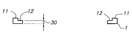
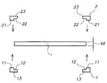
도 1은 제1 형태의 프레임 시스템의 제1 프레임 프로파일의 개략도를 도시한다.
도 2는 축(a-a)에 따른, 제1 형태의 프레임 시스템의 제1 프레임 프로파일의 단면의 개략도를 도시한다.
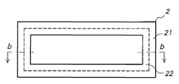
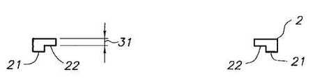
도 3은 제1 형태의 프레임 시스템의 제2 프레임 프로파일의 개략도를 도시한다.
도 4는 축(b-b)에 따른, 제1 형태의 프레임 시스템의 제2 프레임 프로파일의 단면의 개략도를 도시한다.
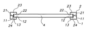
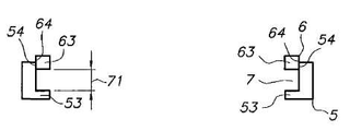
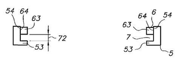
도 5는 제1 프레임 프로파일이 제2 프레임 프로파일 상에 겹친 제1 형태의 프레임 시스템의 단면의 개략도를 도시한다.
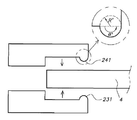
도 6 및 7은 제1 프레임 프로파일이 막 사이에서 제2 프레임 프로파일 상에 겹친 제1 형태의 프레임 시스템의 단면의 개략도를 도시한다.
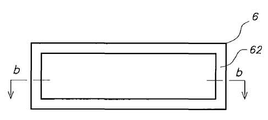
도 8은 제2 형태의 프레임 시스템의 제1 프레임 프로파일의 개략도를 도시한다.
도 9는 축(a-a)에 따른, 제2 형태의 프레임 시스템의 제1 프레임 프로파일의 단면의 개략도를 도시한다.
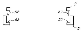
도 10은 제2 형태의 프레임 시스템의 제2 프레임 프로파일의 개략도를 도시한다.
도 11은 축(b-b)에 따른, 제2 형태의 프레임 시스템의 제2 프레임 프로파일의 단면의 개략도를 도시한다.
도 12 내지 14는 제2 프레임 프로파일 상에 제1 프레임 프로파일이 겹친 제2 형태의 프레임 시스템의 단면의 개략도를 도시한다.
도 15 및 16은 제1 프레임 프로파일이 막 사이에서 제2 프레임 프로파일 상에 겹친 제2 형태의 프레임 시스템의 단면의 개략도를 도시한다.
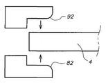
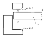
도 17 내지 20은 제1 프레임 프로파일이 막 사이에서 제2 프레임 프로파일 상에 겹치고 프레임 프로파일들의 내부 부분들에 곡선 가장자리들이 제공된 제1 및 제2 형태의 프레임 시스템들의 단면의 개략도를 도시한다.
도 21 및 22는 곡선 가장자리를 가진 내부 부분의 단면의 평면 개략도를 도시한다.
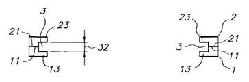
도 23 내지 26은 제1 프레임 프로파일이 막 사이에서 제2 프레임 프로파일 상에 겹치고 프레임 프로파일들의 내부 부분들에 곡선 가장자리가 제공되며 프레임 프로파일들의 내부 및 외부 부분들에 접착 허용 홈들 및 접착 홈이 제공되는 제1 및 제2 형태의 프레임 시스템들의 단면의 개략도를 도시한다.
도 27 내지 30은 제1 프레임 프로파일이 막 사이에서 제2 프레임 프로파일 상에 겹치고 프레임 프로파일들의 내부 부분들에 공간 바가 제공된 제1 및 제2 형태의 프레임 시스템들의 단면의 개략도를 도시한다.
도 31 및 32는 제1 프레임 프로파일이 막 사이에서 제2 프레임 프로파일 상에 겹치고 본 발명의 프레임 프로파일들의 내부 부분들이 막의 표면 상에 부착되며, 막의 표면에 부착된 내부 부분에 의해 형성되고, 액체를 여과하기 위해 사용되는 막의 영역에 가장 인접한, 코너가 밀봉되는 제1 및 제2 형태의 프레임 시스템들의 단면의 개략도를 도시한다.1 shows a schematic diagram of a first frame profile of a first type of frame system.
2 shows a schematic view of a cross section of a first frame profile of a first type of frame system, along axis aa.
3 shows a schematic diagram of a second frame profile of a first type of frame system.
4 shows a schematic view of a cross section of a second frame profile of a frame system of the first form, along axis bb.
5 shows a schematic diagram of a cross section of a frame system of the first type with a first frame profile superimposed on a second frame profile.
6 and 7 show schematic diagrams of cross-sections of a first type of frame system with a first frame profile superimposed on a second frame profile between films.
8 shows a schematic diagram of a first frame profile of a second type of frame system.
9 shows a schematic view of a cross section of a first frame profile of a second type of frame system, along axis aa.
10 shows a schematic diagram of a second frame profile of a second type of frame system.
11 shows a schematic view of a cross section of a second frame profile of a frame system of the second type, along the axis bb.
12-14 show schematic diagrams of cross-sections of a frame system of a second type with a first frame profile superimposed on a second frame profile.
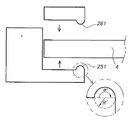
15 and 16 show schematic diagrams of a cross section of a frame system of a second type in which a first frame profile overlaps on a second frame profile between films.
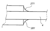
17-20 show schematic views of cross sections of first and second type frame systems in which a first frame profile overlaps a second frame profile between films and provided curved edges in the inner portions of the frame profiles.
21 and 22 show plan schematic views of the cross section of the inner part with curved edges.
23 to 26 show that the first frame profile overlaps between the membranes on the second frame profile and curved edges are provided on the inner portions of the frame profiles and adhesive allowance grooves and adhesive grooves are provided on the inner and outer portions of the frame profiles. A schematic diagram of the cross section of the frame systems of the first and second forms is shown.
27-30 show schematic views of cross sections of first and second type frame systems in which a first frame profile overlaps on a second frame profile between films and a space bar is provided at inner portions of the frame profiles.
31 and 32 show that the first frame profile overlaps between the membranes on the second frame profile and the inner portions of the frame profiles of the present invention are attached on the surface of the membrane and are formed by the inner portion attached to the surface of the membrane, A schematic view of the cross section of the first and second type of frame systems with corners sealed closest to the area of the membrane used for filtration is shown.
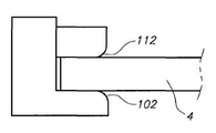
본 발명은 필터 요소를 제공하고, 이는 (i) 유연한 구조를 구비하고 상부 및 하부 막 층 및 사이 막 층들을 지지하기 위한 기질(substrate) 물질을 포함하는 통합된 투과 채널 막(4), 상기 기질은 기정의된 거리에서 단섬유 실들에 의해 함께 묶이고 이격된, 상부 및 하부 직물 표면을 구비하는 3D 공간 직물임, 상기 상부 및 하부 직물 표면 각각에는 상기 상부 및 하부 막 층을 형성하는 적어도 하나의 막 층이 제공되고 투과 채널은 상기 상부 및 하부 막 사이에 개재되고 통합된 투과 채널의 투과의 방출을 위한 출구 개구와 연결됨, 및 (ii) 막의 가장자리에서 상기 통합된 투과 채널을 밀봉하고 상기 막을 지지하는 프레임 시스템을 포함하고, 상기 프레임 시스템은 제1 프레임 프로파일(profile)(1 또는 5) 및 제2 프레임 프로파일(2 또는 6)을 포함하며, 그것들 각각은 막을 둘러쌀 수 있는 형태 및 치수들을 구비하고, 상기 제1 및 제2 프레임 프로파일 각각은 내부 부분들(12, 22 또는 52, 62) 및 외부 부분들(11, 21 또는 54, 64)을 구비하고, 상기 막(4)은 상기 제1 프레임 프로파일(1 또는 5) 및 상기 제2 프레임 프로파일(2 또는 6) 사이에 개재되어서 내부 부분들은 막의 주변에서 상부 및 하부 막 층들의 표면과 접촉하고, 두 개의 프레임 프로파일들의 외부 부분들은 서로 접촉하고 내부 부분들은 막에 맞춰지는 길이방향 채널(3 또는 7)을 형성하고, 막 층들의 표면들과 접촉하고 막 영역에 가장 가까운 내부 부분들의 가장자리는 곡선 형태를 가지고, 접착제가 내부 부분들을 막 층들에 그리고 외부 부분들을 서로 부착하는데 사용된다. 필터 요소의 프레임 시스템은 특히 통합된 투과 채널 막을 지지하고 일 단계 내에서 막의 가장자리를 밀봉하기에 적합하다.The present invention provides a filter element, which comprises: (i) an integrated permeable channel membrane (4) having a flexible structure and comprising a substrate material for supporting the upper and lower membrane layers and the interlayer membrane layers; Is a 3D spatial fabric having a top and bottom fabric surface, bound together and spaced by short fiber yarns at a defined distance, at least one film forming each of the top and bottom membrane layers on the top and bottom fabric surfaces A layer is provided and the permeate channel is connected between the upper and lower membranes and is connected with an outlet opening for the release of permeation of the permeate channel integrated therein, and (ii) sealing the integrated permeate channel at the edge of the membrane and supporting the membrane. A frame system, said frame system comprising a
통합된 투과 채널 막은 막 층들을 지지하는 기질 물질을 포함하고, 상기 기질은, 여기서 또한 "3D 공간 직물(3D spacer fabric)"로 언급되는, 삼-차원 공간 직물이다. 3D 공간 직물은, WO 2006/015461 A1, EP 1 992 400 A1 및 WO 2008/141935 A1에 정의된 바와 같이 기정의된 거리에서 단섬유 실에 의해 이격되고 함께 묶인, 상부 및 하부 직물 표면을 가진다.The integrated permeable channel membrane comprises a substrate material supporting the membrane layers, which is a three-dimensional space fabric, also referred to herein as a "3D spacer fabric". The 3D spatial fabrics have upper and lower fabric surfaces, spaced together by short fiber yarns and bound together at defined distances as defined in WO 2006/015461 A1,
바람직한 실시예에서, 3D 공간 직물의 단섬유들 및 직물 표면들은 WO 2006/015461 A1, EP 1 992 400 A1 및 WO 2008/141935 A1에 정의된 바와 같은 단섬유 실들 내 루프(loop)에 의해 연결된다. 바람직하게, 직물 표면들은 뜨거나(knitted), 짜지거나(woven) 짜지지 않은 형태이다. 상부 및 하부 직물 표면 사이의 거리는 바람직하게 0.5 및 10 mm 사이에 있다. 3D 공간 직물은 바람직하게 폴리에스테르, 나일론, 폴리아미드, 폴리페닐렌 설파이드, 폴리에틸렌 및 폴리프로필렌으로 구성된 그룹으로부터 선택된 물질을 포함한다.In a preferred embodiment, the short fibers and the fabric surfaces of the 3D spatial fabric are connected by loops in short fiber yarns as defined in WO 2006/015461 A1,
IPC 막은 상기 상부 및 하부 직물 표면 상에 적용된 막 층을 포함하고 투과 채널은 상기 두 개의 막 층들 사이에 개재되며, 막 층들은 WO 2006/015461 A1, EP 1 992 400 A1 및 WO 2008/141935 A1d 정의된 바와 같은 상기 상부 및 하부 직물 표면들과 다수의 포인트들에서 연결된다.An IPC membrane comprises a membrane layer applied on the upper and lower fabric surfaces and a permeation channel is interposed between the two membrane layers, the membrane layers being defined in WO 2006/015461 A1,
막 층들은 상기 상부 및 하부 직물 표면의 양 측들에, 바람직하게 코팅 장치 내 막 도프(dope)와 함께 코팅에 의해, 적용된다. 그 후에, 도프는 용제를 제거함으로써 응고되도록 만들어진다. 응고는 상반전(phase inversion) 공정에 의해 수행될 수 있고, 여기서 막 도프의 용제는 막 폴리머의 비-용제(non-solvent)에 의해 도프로부터 추출된다. 상반전은 상기 비-용제의 증기를 포함하는 대기 또는 액체(예를 들어 물) 내에서 수행될 수 있다. 막 형성은 또한 용제의 증발에 의해 얻어질 수 있다(건식 상반전). 상반전 공정은 외측으로부터 시작된다.Membrane layers are applied to both sides of the upper and lower fabric surfaces, preferably by coating with a film dope in the coating apparatus. Thereafter, the dope is made to solidify by removing the solvent. Solidification can be carried out by a phase inversion process, where the solvent of the membrane dope is extracted from the dope by non-solvents of the membrane polymer. Phase inversion can be performed in the atmosphere or liquid (eg water) containing the vapor of the non-solvent. Film formation can also be obtained by evaporation of the solvent (dry phase inversion). The phase inversion process starts from the outside.
IPC 막은 유연한 구조를 가져서 막은 롤러 상에서 접히거나 끝난다. 이는 막이 플레이트 물질의 강도를 가지지 않음을 의미한다.The IPC membrane has a flexible structure so that the membrane is folded or finished on a roller. This means that the membrane does not have the strength of the plate material.
막들은 보통 비대칭 구멍 크기 배치를 가지고, 여기서 가장 작은 구멍들은 공급 측에 존재한다. 그래서 큰 입자들은 막 층을 침투할 수 없고 막은, 예를 들어 백플러시(backflush)를 적용하는 것에 의해, 쉽게 세척된다. 또는, 입자들은 막을 침투할 수 있고 막 층 내부의 구멍을 막는다. 구멍 크기 배치는 응고 단계 동안 맞춰지고 IPC 막의 양 측들에서의 내부 및 외부 표면들은 동일 범위로 응고제에 노출되지 않아야 한다. 비대칭 구멍 크기 배치는 증기 상에서 응고에 의해 실현될 수 있다. 또한 3D 공간 직물이 코팅된 막 도프를 구비한 가장자리들이 응고제가 투과 채널 안으로 침투하는 것을 방지하기 위해 응고 단계 전에 밀봉될 때 이러한 비대칭 구멍 크기 배치를 얻을 수 있다. 본 기술에서, 이는 막을 코팅하기 전 분리 단계에서 이루어질 수 있고 이는 EP 1 992 400 A1 및 WO 2008/141935 A1에 기술된 바와 같은 코팅 단계와 함께 이루어질 수 있다. Membranes usually have an asymmetric pore size arrangement, where the smallest holes are on the feed side. So large particles cannot penetrate the membrane layer and the membrane is easily washed, for example by applying a backflush. Alternatively, the particles can penetrate the membrane and block the pores inside the membrane layer. The pore size placement is tailored during the solidification step and the inner and outer surfaces on both sides of the IPC membrane should not be exposed to the coagulant to the same extent. Asymmetric pore size placement can be realized by solidification on the vapor. This asymmetric pore size arrangement can also be obtained when the edges with the film dope coated with the 3D spatial fabric are sealed before the coagulation step to prevent the coagulant from penetrating into the permeation channel. In the present technique, this can be done in a separation step prior to coating the membrane and this can be done in conjunction with a coating step as described in
막 층은 바람직하게 폴리설폰(PSU), 폴리바닐린 클로라이드(PVC), 폴리아크릴로나이트릴(PAN), 폴리에스테르, 폴리에테르설폰(PES), 폴리에테르케톤(PEK), 폴리에테르에테르케톤(PEEK), 폴리바닐리덴 플루오라이드(PVDF), 폴리바닐 아세테이트(PVAc), 폴리바닐 알콜(PVA), 폴리아미드(PA), 폴리바닐피롤리돈(PVP), 교차결합된 PVP, 셀룰로스 아세테이트(CA) 및 셀룰로스 트리아세테이트(CTA)와 같은 셀룰로스 화합물들, 폴리카보네이트 블록 폴리머들로 구성된 그룹으로부터 선택된 막 폴리머를 포함하고, 실리콘 고무, 폴리메틸펜텐, 플로로그렌, SBR, NBR, 우레탄, 하이팔론(Hupalon®), 네오프렌, 니트릴, 부나, 우레탄, 데피클로로하이드린, 비톤(Viton®), EPDM, 부틸, 천연고무(Latex), 아크릴고무, 플로로엘라스토머들 및 펄플루오로엘라스토머들로 구성된 그룹으로부터 선택된 고무를 포함하거나 그것의 혼합물들/합성물들을 포함한다. 다른 적합한 막 폴리머들은 클로리네이티드 폴리바닐 클로라이드(CPVC), 예를 들어 바닐 클로라이드 또는 에틸 아크릴레이트와 같은 아크릴로나이트릴의 코폴리머들, 폴리에틸렌 석시네이트(PESU), 폴리우레탄들(PU), 폴리이미드들(PI), 폴리에테리미드(PEI) 및 하이트록시프로필 셀룰로스(HPC), 카르복실메틸 셀룰로스(CMC) 및 셀룰로스 트리카르바닐레이트(CTC)와 같은 셀룰로스 화합물, 그것의 혼합물/화합물들 및 그것들의 접합된 파생물들(술폰기, 아크린산염, 아민 등)을 포함한다. 막 층은 또한 폴리비닐 피롤리돈(PVP), 교차결합된 폴리비닐피롤리돈(PVPP), 폴리비닐 알콜, 폴리비닐 아세테이트, 메틸 셀룰로스 및 폴리에틸렌 산화물과 같은 친수성 폴리머들을 포함할 수 있다. 막 층은 또한 Ti02, Al203, Zr02, Zr3(P04)fY203, Si02, 페로브스키트(perovskite) 산화물 물질 및 SiC와 같은 친수성 무기 물질들을 포함할 수 있다.The membrane layer is preferably polysulfone (PSU), polyvanillin chloride (PVC), polyacrylonitrile (PAN), polyester, polyethersulfone (PES), polyetherketone (PEK), polyetheretherketone (PEEK) ), Polyvanylidene fluoride (PVDF), polyvanyl acetate (PVAc), polyvanyl alcohol (PVA), polyamide (PA), polyvanylpyrrolidone (PVP), crosslinked PVP, cellulose acetate (CA ) And cellulose compounds such as cellulose triacetate (CTA), membrane polymers selected from the group consisting of polycarbonate block polymers, silicone rubber, polymethylpentene, phlogrogene, SBR, NBR, urethane, hypalon ( Hupalon®), neoprene, nitrile, buna, urethane, depichlorohydrin, Viton®, EPDM, butyl, natural rubber (Latex), acrylic rubber, fluoroelastomers and perfluoroelastomers Selected high To include, or include it in the mixture / composite. Other suitable membrane polymers are chlorinated polyvanyl chloride (CPVC), for example copolymers of acrylonitrile, such as vanyl chloride or ethyl acrylate, polyethylene succinate (PESU), polyurethanes (PU), poly Cellulose compounds such as mids (PI), polyetherimides (PEI) and hydroxypropyl cellulose (HPC), carboxymethyl cellulose (CMC) and cellulose tricarvanylate (CTC), mixtures / compounds thereof, and Their conjugated derivatives (sulfone groups, acrates, amines, etc.). The membrane layer may also include hydrophilic polymers such as polyvinyl pyrrolidone (PVP), crosslinked polyvinylpyrrolidone (PVPP), polyvinyl alcohol, polyvinyl acetate, methyl cellulose and polyethylene oxide. The film layer may also include hydrophilic inorganic materials such as Ti02, Al203, Zr02, Zr3 (P04) fY203, Si02, perovskite oxide material and SiC.
막 도프는 막 폴리머를 포함하는 액체 중합 용액이고, 10,000 내지 50,000 s-1의 범위 내 점도를 가진, 10 s-1의 전단(shear)에서 바람직하게 1000 및 100,000 사이 점도를 가진다. 막 도프는 막 폴리머, 친수성 충전 물질, N-메틸-피롤리돈(NMP), N-에틸-피롤리돈(NEP), N,N-디메틸포르말마이드(DMF), 포르말마이드, 디에틸설포사이드(DMSO), N,N-디메틸아세트아미드(DMAC), 테트라하이드로푸란(THF), 아세톤, 트리에틸포스페이트 및 그것의 혼합물들과 같은 비양자성 용제 및 글리세롤과 같은 안정제를 포함한다. 글리세롤과 같은 친수 및 안정제들은 또한 상반전 공정이 완료된 후에 포함될 수 있지만, 건조 전에 포함될 수 있다. 친수성 충전제는 막의 친수 및 그것의 부착(fouling) 거동에 영향을 미친다. 종종 용제 혼합물 내 변화가 다른 필름 형태를 일으킬 것이어서 막 성능을 향상시킬 것이다. 물 안에 폴리술폰-NMP의 침전에 의해 형성된 필름들은 다공성이다. 그러나, 다른 막 구조들이 물 내에 폴리술폰-NMP-THF 용액의 침전시 얻어질 수 있다.The membrane dope is a liquid polymerization solution comprising a membrane polymer and preferably has a viscosity between 1000 and 100,000 at a shear of 10 s −1 having a viscosity in the range of 10,000 to 50,000 s −1. Membrane dope includes membrane polymers, hydrophilic fillers, N-methyl-pyrrolidone (NMP), N-ethyl-pyrrolidone (NEP), N, N-dimethylformalmide (DMF), formalamide, diethyl Aprotic solvents such as sulfoside (DMSO), N, N-dimethylacetamide (DMAC), tetrahydrofuran (THF), acetone, triethylphosphate and mixtures thereof and stabilizers such as glycerol. Hydrophilic and stabilizers such as glycerol may also be included after the phase inversion process is completed, but may be included before drying. Hydrophilic fillers affect the hydrophilicity of the membrane and its fouling behavior. Often changes in the solvent mixture will result in different film morphologies that will improve membrane performance. Films formed by precipitation of polysulfone-NMP in water are porous. However, other membrane structures can be obtained upon precipitation of the polysulfone-NMP-THF solution in water.
IPC 막은 WO 2006/015461 A1, EP 1 992 400 A1 및 WO 2008/141935 A1에 정의된 바와 같은 투과 채널로부터 투과를 추출하기 위해 제공된 배수 파이프를 더 포함한다.The IPC membrane further comprises a drain pipe provided for extracting the permeation from the permeation channel as defined in WO 2006/015461 A1,
프레임 시스템Framing system
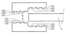
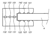
본 발명의 필터 요소는 막의 가장자리에서 통합된 투과 채널을 밀봉하고 IPC 막을 지지하기 위한, 여기서 또한 "프레임"으로 언급되는, 프레임 시스템을 더 포함한다. 프레임 시스템은 제1 프레임 프로파일(도 1 내지 7에서 도면부호 1 또는 도 8 내지 16에서 도면부호 5 참조) 및 제2 프레임 프로파일(도 1 내지 7에서 도면부호 2 또는 도 8 내지 16에서 도면부호 5 참조)를 포함하고, 그것들 각각은 막을 둘러쌀 수 있는 치수들 및 형태를 가진다. 두 형태의 프레임 시스템들은 본 발명 내에 정의되고, 일면 제1 형태의 프레임 시스템은 도 1 내지 7에 나타나고 제2 형태의 프레임 시스템은 도 8 내지 16에 나타난다.The filter element of the present invention further comprises a frame system, here also referred to as "frame", for sealing the integrated permeate channel at the edge of the membrane and for supporting the IPC membrane. The frame system comprises a first frame profile (
제1 및 제2 프레임 프로파일들 각각은 내부 부분들(도 1 내지 7에서 도면부호 12 및 22, 도 8 내지 16에서 도면부호 52 및 62 참조) 및 외부 부분들(도 1 내지 7에서 도면부호 11 및 21, 또는 도 8 내지 16에서 도면부호 54 및 64 참조)을 구비한다. IPC 막(4)은 제1 프레임 프로파일(1 또는 5) 및 제2 프레임 프로파일(2 또는 6) 사이에 개재되어서 내부 부분들은 막의 주변에서 상부 및 하부 막의 표면과 접촉하고, 두 개의 프레임 프로파일들의 외부 부분들은 서로 접촉하며, 내부 부분들은 막에 맞는 길이방향 채널(3 또는 7)을 형성한다. 이러한 길이방향 채널(3 또는 7)은, 도 5, 13 또는 1에 도시된 바와 같이, 제1 및 제2 프레임 프로파일의 내부 부분에 의해 형성된, 제1 및 제2 채널 플랜지(13, 23 또는 53, 63)를 구비한다.Each of the first and second frame profiles has internal portions (12 and 22 in FIGS. 1 through 7 and 52 and 62 in FIGS. 8 through 16) and external portions (11 in FIGS. 1 through 7). And 21 or 54 and 64 in FIGS. 8 to 16. The
상기 길이방향 채널(3 또는 7)의 폭(32 또는 71, 72)은 프로파일들이 제1 및 제2 프레임 프로파일 사이 막을 개재하기 위해 위에서 정의된 방식으로 서로 겹쳐질 때 내부 부분들(12 및 22, 또는 52 및 62) 사이의 거리이다.The
프레임 시스템의 제1 형태를 위해, 폭(32)은, 막의 두께에 매칭(matching)하는, 제1 및 제2 프레임 프로파일의 두 개의 두께들(30 및 31)의 합에 의해 형성된, 고정된 값을 가진다.For the first form of the frame system, the
제2 형태의 프레임 시스템에 대한 폭(71 또는 72)은 고정된 값이 아니고, 넓은 범위의 값들 내에서 변화할 수 있다. 최소값은 없고, 오직 최대 폭은 , 도 13 내지 16에 도시된 제1 프레임 프로파일의 외부 부분(54) 및 제2 프레임 프로파일의 외부 부분(64) 사이에 겹쳐진 표면의 거리에 의해 감소된, 막의 제1 프레임 프로파일의 외부 부분의 두께(70)에 따라 달라진다. 도 13에 예시된 바와 같이, 최소 표면 겹침은 양 부분들이 서로 충분히 강하게 고정되어서 막은 길이방향 채널 안으로 단단히 고정되게 유지되는 방식으로 제1 프레임 프로파일의 외부 부분(54) 및 제2 프레임 프로파일의 외부 부분(64)에 부착될 수 있기 위해 필요하다. 이러한 제2 형태의 프레임 시스템의 길이방향 채널(71 또는 72)을 위한 이러한 넓은 범위의 값들은 다른 두께들을 가지는 막들의 다른 형태들이 프레임 시스템의 오직 일 형태에 의해 지지될 수 있다는 이점을 가진다. 이는 다른 두께들을 가지는 막들의 다른 형태의 넓은 범위를 지지하기 위해 사용될 수 있는 오직 일 형태의 프레임 시스템만이 제조될 필요가 있기 때문에 훨씬 낮은 비용을 야기할 수 있다.The
막(4)은 접착제 의해 외부 부분들(11, 21 또는 54, 64) 및 막 층들의 각 측면의 표면에 내부 부분들(12, 22 또는 52, 62)을 부착함으로써 길이방향 채널 내에 고정된다. 접착제는 합성 또는 천연 수지, 압력 민감 핫-멜트(hot-melt) 수지들과 같은 핫-멜트 수지로부터 선택될 수 있고, 에폭시 또는 폴리우레탄 수지들이 사용될 수 있다. 접착제는 바람직하게 접착제를 형성하도록 서로 반응할 수 있는 적어도 두 개의 다른 혼합물들을 포함하는 혼합된 접착제이다. 두 성분의 폴리우레탄 수지 또는 두 성분의 에폭시 수지가 가장 바람직하고 적어도 두 개의 이소시아네이트 그룹들을 포함하는 혼합물 또는 적어도 두 개의 에폭시 그룹들을 포함하는 혼합물이 폴리올 혼합물 또는 폴리아민 혼합물, 즉 적어도 두 개의 하이드록실기 또는 아민 그룹들을 가지는 혼합물과 반응하도록 첨가될 수 있는 구성 내 하나의 반응 혼합물로서 이용된다. 본 발명의 실시예에서, "젖은(wet)" 막들, 즉 접착제를 적용하기 전에 건조되지 않은 막들의 부착을 위해, 물 흡수제들이 바람직하게 접착제에 첨가된다. 물 흡수제들은 천연 또는 합성 다공성 물질의 형태일 수 있다. 다공성 물질은 바람직하게 무기 실리케이트, 제올라이트 도는 분자체이고, 더 바람직하게는 분자체이다. 다공성 물질은 바람직하게, 0.2 및 0.8nm 사이의 범위, 더 바람직하게는 0.3 및 0.5nm 사이의 범위에 있는 구멍 크기를 가진다. 다공성 물질은 바람직하게 0.5nm보다 작은, 더 바람직하게는 100μTη보다 작은, 가장 바람직하게는 0.5 및 30μTη 사이의 입자 지름을 가진다. 젖은 조건들 내 막들에 대해, 분자체와 같은 물 흡수제는 바람직하게 1 및 50 중량% 사이, 더 바람직하게는 5 및 40 중량% 사이 범위의 야의 접착제에 첨가된다. 물 흡수제는 접착제에 추가되어 막 표면들에 프레임의 내부 부분들을 부착하고 외부 부분들을 서로 부착한다.The
막 층들의 표면들과 접촉하고 막 영역에 가장 가까운, 제1 및 제2 프레임 프로파일들의 내부 부분들의 가장자리는 곡선 형태(도 17 및 18에서 도면부호 82 및 92 또는 도 19 및 20에서 도면부호 102 및 112 참조)를 가진다. 이는, 막 표면이 프레임 프로파일들의 두 개의 내부 부분들 사이에서 접촉하고 막의 여과 영역에 가장 가까운, 제1 및 제2 프레임 프로파일들의 채널 플랜지들(13, 23, 53, 63)의 가장자리들이 곡선 형태를 가지는 것을 의미한다. 이러한 가장자리들의 곡선 형태가 도 17 내지 20에서 지시되지만 도 1 내지 16에서 그러한 가장자리의 곡선 형태는 나타나지 않음을 주목하라.The edges of the inner portions of the first and second frame profiles, which are in contact with the surfaces of the membrane layers and closest to the membrane area, are curved (see figures 82 and 92 in FIGS. 17 and 18 or 102 and in FIGS. 19 and 20). 112). This means that the edges of the
프레임 시스템에서 지지될 때 및/또는 여과 공정에서 사용될 때, 특히 세척 가스가 잠긴 여과 모듈 안으로 아래로부터 도입되고 가스의 더 높은 흐름 속도가 막 표면의 영역 내 프로펠러들이나 펌프들에 의해 침전물들로부터 여과 막들을 세척하기 위해 생성될 때, 곡선의 라운딩(rounding)은 막을 손상시킬 위험을 감소시키고 막을 손상시키지 않기 위해 충분히 클 필요가 있다. (이러한 세척 과정의 설명은 US 2008/827 A1에 기술된다.) 이러한 손상은 막 층 내 크랙이나 찢김일 수 있으며, 막의 누설을 야기한다. 가장자리의 라운딩은 반경(R) 및 각도를 가지는 원의 일부에 의해 나타날 수 있다. 이러한 라운딩은, 반경(R)이 클 때, 막 표면을 손상시키지 않기에 충분히 크다. 반경(R)이 작을 때, 각도는, 도 21 및 22에 도시된 바와 같이, 반경이 클 때보다 더 클 필요가 있다. 바람직한 실시예에서, 각도(α)는 3 및 120도 사이, 더 바람직하게는 5 및 90도 사이 범위에 있고, 반경(R)은 바람직하게, 0.5 및 50nm 사이, 더 바람직하게는 1 및 30nm 사이, 가장 바람직하게는 1.5 및 20nm 사이의 범위에 있다.When supported in the frame system and / or used in the filtration process, in particular the cleaning gas is introduced from below into the submerged filtration module and a higher flow rate of gas is introduced from the filtration membranes from the precipitates by propellers or pumps in the region of the membrane surface. When produced to clean the grass, the rounding of the curve needs to be large enough to reduce the risk of damaging the membrane and not damage the membrane. (A description of this cleaning procedure is described in US 2008/827 A1.) Such damage may be cracks or tears in the membrane layer, resulting in membrane leakage. The rounding of the edges can be represented by a portion of the circle having a radius R and an angle. This rounding is large enough not to damage the film surface when the radius R is large. When the radius R is small, the angle needs to be larger than when the radius is large, as shown in FIGS. 21 and 22. In a preferred embodiment, the angle α is in a range between 3 and 120 degrees, more preferably between 5 and 90 degrees, and the radius R is preferably between 0.5 and 50 nm, more preferably between 1 and 30 nm. Most preferably in the range between 1.5 and 20 nm.
상술한 바와 같은 방식으로 서로에 겹쳐질 때 제1 및 제2 프레임 프로파일들의 형태 및 치수들은 막의 형태 및 치수들과 매칭되어서 제1 및 제2 프레임 프로파일들은 막을 둘러쌀 수 있다.When superimposed on each other in the manner described above, the shape and dimensions of the first and second frame profiles can match the shape and dimensions of the film so that the first and second frame profiles can surround the film.
막을 둘러싸는 프레임 프로파일들의 형상은 직사각형, 정사각형, 다이아몬드형, 삼각형, 원형 또는 반원형일 수 있고, 바람직하게 직사각형일 수 있다.The shape of the frame profiles surrounding the membrane may be rectangular, square, diamond, triangular, circular or semicircular, and preferably rectangular.
바람직한 실시예에서, 제1 형태의 프레임 시스템의 두 개의 프레임 프로파일들은 동일한 형태를 가진다. 이는 오직 하나의 형태의 프레임 프로파일이 제조되고 이러한 프레임 프로파일은 제1 및 제2 프레임 프로파일로 사용될 수 있는 추가적인 이점을 가져서, 프레임 프로파일들의 제조 비용을 훨씬 더 낮춘다. 막의 가장자리에서 IPC를 밀봉하고 막을 지지하는 방법에서, 제1 및 제2 프레임 프로파일들은 서로 반사하고 서로에 대해 겹쳐져서 길이방향 채널 내 채널 플랜지들에 의해 막을 고정한다.In a preferred embodiment, two frame profiles of the first type of frame system have the same shape. This allows only one type of frame profile to be manufactured and this frame profile has the additional advantage that it can be used as the first and second frame profiles, thus lowering the manufacturing cost of the frame profiles even further. In the method of sealing the IPC at the edge of the membrane and supporting the membrane, the first and second frame profiles reflect from one another and overlap with each other to secure the membrane by channel flanges in the longitudinal channel.
본 발명의 다른 실시예에서, 상술한 바와 같이 각각이 내부 및 외부 부분을 가지는, 제1 형태의 프레임 시스템의 제1 및 제2 프레임 프로파일은 동일하거나 다른 형태를 가질 수 있다. "동일한 형태"는 필수적인 특징들이 동일하지만 필수적이지 않은 특징들은 다를 수 있음을 의미한다. "다른 형태"는 필수적인 특징들은 두 프레임 프로파일들 내에서 다름을 의미한다. 그러한 필수적인 특징들의 예들은 제2 프레임 프로파일의 두께(31)보다 클 수 있는 제1 프레임 프로파일의 두께(30), 도는 제2 프레임 프로파일보다 클 수 있는 제1 프레임 프로파일의 내부 부분들(12)의 표면, 또는 제2 프레임 프로파일(21)보다 클 수 있는 제1 프레임 프로파일의 외부 부분들(11)의 표면, 또는 제2 프레임 프로파일의 외부 부분 내에 존재하는 구멍들 안으로 맞춰질 수 있는 제1 프레임 프로파일의 외부 부분 내 융기들의 존재이다.In another embodiment of the present invention, the first and second frame profiles of the first type of frame system, each having internal and external portions as described above, may have the same or different shapes. "Identical form" means that essential features are the same, but non-essential features may be different. "Other forms" means that the essential features are different within the two frame profiles. Examples of such essential features are the
본 발명의 실시예에서, 필터 요소를 제조하는 방법이 제공되고, 상기 방법은 다음 단계들을 포함한다:In an embodiment of the invention, a method of manufacturing a filter element is provided, the method comprising the following steps:
- 위에 정의된 바와 같은 IPC 막(4)을 제공하는 단계,Providing an
- 위에 정의된 바와 같은 제1 프레임 프로파일(1 또는 5) 및 제2 프레임 프로파일(2 또는 6)을 제공하는 단계,Providing a
- 막이 제1 프레임 프로파일의 내부 부분(12 또는 52)과 접촉하도록 제1 프레임 프로파일 상에 막(4)을 장착하는 단계,Mounting the
- 제2 프레임 프로파일을 제1 프레임 프로파일에 겹치는 단계, 막이 제2 프레임 프로파일의 내부 부분(22 도는 62)과 접촉하고 제1 및 제2 프레임 프로파일들의 외부 부분들(11, 21 도는 54, 64)이 서로 접촉하도록 막이 존재함,Overlapping the second frame profile with the first frame profile, the film contacting the inner part (22 or 62) of the second frame profile and the outer parts (11, 21 or 54, 64) of the first and second frame profiles Membranes are present so that they contact each other,
- 막의 일 표면에 제1 프레임 프로파일의 내부 부분(12 또는 52) 사이에, 막의 다른 표면에 제2 프레임 프로파일의 내부 부분(22 또는 62) 사이에 그리고 제1 및 제2 프레임 프로파일들의 외부 부분들(11, 21 또는 54, 64) 사이에 접착제를 적용하는 단계, 및Between the
- 막의 표면 중 하나에 제1 및 제2 프레임 프로파일의 내부 부분 및 서로에 제1 및 제2 프레임 프로파일들의 외부 부분들을 부착하는 단계.-Attaching the inner part of the first and second frame profiles to one of the surfaces of the membrane and the outer parts of the first and second frame profiles to each other.
필터 요소의 프레임 시스템은 특히 IPC 막을 지지하기 적합하고 하나의 단일 단계 내에서 막의 가장자리를 밀봉하기 적합하다. 막의 가장자리들이 밀봉될 때, 두 막 표면들 사이에 개재된, 통합된 투과 채널은 여과 공정 동안 투과물(permeate)을 수집하기 위해 형성된다. 그러므로, 막의 가장자리들은 막의 주변에서 아주 조심스럽게 밀봉되어서 막 층을 통한 통과 없이 투과 채널로부터 또는 투과 채널로의 직접적인 유체 이동을 방지하여야 한다. 본 발명의 프레임 시스템은 막 상에 매우 편리하게 적용될 수 있어서 막의 주변에서의 가장자리가 길이방향 채널 내에서 그것을 부착함으로써, 즉 막 표면에 내부 부분들을 부착하고 외부 부분들을 서로 부착함으로써 밀봉된다는 이점을 가진다. 프레임 시스템의 존재는 가장자리의 밀봉을 안정화하고, 특히 프레임 프로파일들을 서로에 대한 그리고 막에 대한 모든 부착들이 점착제에 의해 수행될 때, 더 바람직하게는 위에서 정의된 바와 같이 두 성분의 폴리우레탄 또는 에폭시 수지에 의해 부착될 때, 누설들의 위험을 방지한다.The frame system of the filter element is particularly suitable for supporting the IPC membrane and for sealing the edges of the membrane in one single step. When the edges of the membrane are sealed, an integrated permeate channel, interposed between the two membrane surfaces, is formed to collect permeate during the filtration process. Therefore, the edges of the membrane must be very carefully sealed around the membrane to prevent direct fluid movement from or to the permeate channel without passing through the membrane layer. The frame system of the present invention has the advantage that it can be applied very conveniently on the membrane so that the edge at the periphery of the membrane is sealed by attaching it in the longitudinal channel, ie attaching the inner parts to the membrane surface and attaching the outer parts to each other. . The presence of the frame system stabilizes the sealing of the edges, especially when all the attachments of the frame profiles to each other and to the membrane are carried out by means of an adhesive, more preferably a two component polyurethane or epoxy resin as defined above When attached by means of, it prevents the risk of leaks.
이러한 가장자리들이 완벽한 밀봉은 여과 공정 동안 그리고 백워싱(backwashing) 공정 동안 고압들이 이용될 수 있는 추가적인 이점을 가진다.Perfect sealing of these edges has the additional advantage that high pressures can be used during the filtration process and during the backwashing process.
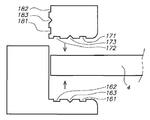
공간이 IPC 막 사이에 제공되고, 내부 부분들 상에 그리고 프레임 프로파일의 외부 부분들 상에 부착될 때, 프레임 시스템의 존재에 의한 가장자리들의 완벽한 밀봉은 내부 윤곽 채널(24 또는 25)이 프레임 시스템의 내측에 형성될 수 있는 추가적인 이점을 가진다. 이러한 추가적인 내부 투과 채널은 내부 투과 채널과 연결되고 배수 개구 또는 파이프와 연결된다. 배수 개구 또는 파이프는 도면에 도시되지 않는다. 이러한 추가적인 내부 투과 채널은 투과 액체의 증가한 유동을 제공하여서, 감소된 막힘을 더 야기할 수 있는 막의 투과 측에 감소된 압력 손실을 야기한다. 이러한 추가적인 내부 투과 채널의 존재는, 백워싱 공정 동안, 통합된 투과 채널 안으로 투과물의 역류율이 증가되어서 더 빠르고 효율적인 백워싱 공정을 야기한다는 이점을 가진다.When space is provided between the IPC films and attached on the inner parts and on the outer parts of the frame profile, complete sealing of the edges by the presence of the frame system results in an
본 발명의 프레임 시스템은 유연한 필터 요소의 강성 및 강도를 증가시키는 이점을 가지고, 3D 공간 직물은 지지부로서 이용된다. 이러한 증가된 강도로 인해, 막들 사이의 막간 거리는, 예를 들어 필터 모듈 내에서, 위쪽 공기 흐름에 의해 영향을 덜 받는다. 이는 여과 공정 동안 작은 막간 거리들의 발생이 줄어들고 막 층들을 손상시키고 막힘의 줄어든 경향을 야기함을 의미한다.The frame system of the present invention has the advantage of increasing the stiffness and strength of the flexible filter element, and 3D spatial fabrics are used as supports. Due to this increased strength, the intermembrane distance between the membranes is less affected by the upper air flow, for example within the filter module. This means that the occurrence of small interlude distances during the filtration process is reduced, damaging the membrane layers and causing a reduced tendency of clogging.
본 발명의 필터 요소는 모듈 필터 시스템으로서 이용될 수 있는 이점을 가지고, 필터 요소들은 필터 모듈 내에 쉽게 장착될 수 있고, 필터 요소가 누설이나 많은 막임으로 인해 효율적으로 작동하지 않을 때, 그것은 다른 필터 요소로 수비게 빠르게 대체될 수 있다.The filter element of the present invention has the advantage that it can be used as a modular filter system, and the filter elements can be easily mounted in the filter module, and when the filter element does not operate efficiently due to leakage or a large number of membranes, it is used as another filter element. Can be replaced quickly.
내부 및/또는 외부 부분 상의 접착제 허용 홈을 구비한 프레임 프로파일Frame profile with adhesive tolerant grooves on inner and / or outer parts
본 발명의 다른 실시예에서, 프레임 시스템들의 제1 및 제2 형태의 프레임 프로파일의 내부 부분들은 접착제의 이용에 의해 막의 표면에 부착되고, 이러한 내부 부분들에는 적어도 하나의 접착제 허용 홈, 즉 내부 부분 또는 막 표면 상에 가해진 초과 접착제가 모일 수 있는 홈이 제공된다. 본 발명의 바람직한 실시예에서, 접착제 허용 홈(121, 141, 161, 171)은, 접착제가 적용되고 막의 여과 영역에 가장 가까운 위치 옆에, 막 표면 상에 부착되도록 측면에 존재한다. 도 23 내지 26에서 두 개의 접착제 허용 홈들이 나타나 있고 도한 하나의 접착제 홈이 나타나 있음을 주목하라.In another embodiment of the invention, the inner parts of the frame profile of the first and second forms of the frame systems are attached to the surface of the membrane by the use of an adhesive, the inner parts having at least one adhesive accepting groove, ie the inner part. Or a groove is provided in which excess adhesive applied on the membrane surface can collect. In a preferred embodiment of the present invention, the
이러한 접착제 허용 홈의 존재는 부착 동안 뿌려진 초과 접착제가, 막 필터의 감소된 여과 능력을 야기하는, 여과 막 영역을 더럽히지 않거나, 가장자리에서 막을 손상시킬 증가된 위험을 야기하는, 내부 부분 상의 곡선 가장자리를 더럽히지 않도록 방지될 수 있다. 초과 접착제를 수용하기 위해서, 홈의 부피는 바람직하게 초과된 접착제의 양보다 크다. 바람직한 실시예에서, 홈은 0.3mm, 더 바람직하게는 0.5mm, 가장 바람직하게는 0.8mm의 깊이를 가지고, 적어도 0.5mm, 더 바람직하게 적어도 1mm, 가장 바람직하게 적어도 2mm의 폭을 가진다.The presence of such adhesive tolerant grooves results in the curved edge on the inner portion, which causes excess glue sprayed during attachment, which does not contaminate the filtration membrane area, which results in reduced filtration capability of the membrane filter, or increases the risk of damaging the membrane at the edge. Can be prevented from being soiled. In order to accommodate excess adhesive, the volume of the grooves is preferably greater than the amount of excess adhesive. In a preferred embodiment, the groove has a depth of 0.3 mm, more preferably 0.5 mm, most preferably 0.8 mm and a width of at least 0.5 mm, more preferably at least 1 mm, most preferably at least 2 mm.
위에 설명한 바와 같은 접착제 허용 홈의 존재에 더하여, 다른 접착제 허용 홈(122, 142, 162 및 172)이 제1 접착제 허용 홈과 같은 동일한 측면에 제1 프로파일의 내부 부분 상에 존재할 수 있다. 이러한 제2 접착제 허용 홈은 바람직하게 도 23 내지 26에서 나타난 바와 같이 접착제가 적용되는 위치의 다른 측면 옆에 존재한다. 제2 접착제 허용 홈은 프레임 프로파일의 내부 부분의 주변 상에 존재하고 적어도 0.3mm, 더 바람직하게 적어도 0.5mm, 가장 바람직하게 0.8mm의 깊이를 가지고, 적어도 0.5mm, 더 바람직하게 적어도 1mm, 가장 바람직하게 적어도 2mm의 폭을 가진다. 이러한 다른 홈은, 부착 동안 뿌려지는 초과하는 접착제가 프레임 시스템의 내측을 더럽히지 않도록 방지될 수 있는 이점을 가진다. 프레임 시스템의 내측 내에 존재하는 초과하는 접착제가 막의 여과 영역의 방향에서 막 내에서 이동할 수 있을 때, 이는, 본 발명의 프레임 시스템에 의해 지지된 IPC 막을 위해 위에서 정의된 바와 같은 프레임 시스템의 내측에 형성된, 내부 윤곽 채널을 방해하거나 막을 수 있다.In addition to the presence of adhesive allowances as described above, other
본 발명의 다른 실시예에서, 프레임 프로파일들의 외부 부분들이 접착제의 사용에 의해 서로 부착될 때, 적어도 하나의 이러한 외부 부분들, 바람직하게 두 개의 프레임 프로파일들의 양 외부 부분들에는 적어도 하나의 접착 허용 홈, 즉 외부 부분 상에 가해진 초과 접착제가 모일 수 있는 홈이 제공된다.In another embodiment of the invention, when the outer parts of the frame profiles are attached to each other by the use of an adhesive, at least one adhesive accepting groove is provided in at least one such outer parts, preferably in both outer parts of the two frame profiles. That is, a groove is provided in which excess adhesive applied on the outer portion can collect.
제1 형태의 프레임 시스템에 대해, 접착제 허용 홈(131, 151)은, 접착제가 가해지는 위치 옆에, 프레임 시스템의 내측에 가장 가까운, 다른 외부 부분들에 부착되도록 측면에서 외부 부분 상에 존재한다(도 23 및 24). 이러한 접착제 허용 홈은 프레임 프로파일의 주변 상에 존재하고 위에서 정의된 바와 같은 동일한 깊이와 폭을 가질 수 있다. 이러한 홈은 부착 동안 뿌려진 초과 접착제가 프레임 시스템의 내측을 더럽히지 않도록 하기 위해 방지될 수 있는 이점을 가진다. 프레임 시스템의 내측 내 초과 접촉제의 존재가 막의 여과 영역의 방향 내에서 막 안에서 일동할 때, 이는 또한 막 필터의 여과 능력을 감소시킬 수 있다. 위에서 설명한 바와 같은 이러한 접착제 허용 홈의 존재에 더하여, 제2 접착제 허용 홈(132, 152)이 이러한 외부 부분들 중 적어도 하나 위에 존재할 수 있고, 바람직하게 접착제가 가해지는 위치의 다른 측면 옆에, 두 개의 프레임 프로파일들의 양 외부 부분들 상에 존재할 수 있다(도 23 및 24). 이러한 제2 접착제 허용 홈은 프레임 프로파일의 주변 상에 존재할 수 있고 위에서 설명한 바와 동일한 깊이와 폭을 가질 수 있다. 이러한 다른 홈은, 부착 동안 뿌려지는, 접착제의 초과가 프레임 시스템의 외측을 더럽히지 않도록 하기 위해 방지될 수 있는 이점을 가진다.For the frame system of the first type, the adhesive accepting
제2 형태의 프레임 시스템에 대해, 제1 프레임 프로파일의 외부 부분(54)은 접착제의 이용에 의해 제2 프레임 프로파일의 외부 부분(64)에 부착되고, 외부 부분(54, 64) 중 하나 또는 양자에는 적어도 하나의 접착제 허용 홈, 즉 내부 부분 상에 가해진 초과 접착제가 모일 수 있는 홈이 제공되고, 바람직하게 접착제 홈은 도 25 및 26에 도시된 바와 같이 제2 프레임 프로파일의 외부 부분(64) 상에 존재한다. 바람직한 실시예에서, 접착제 허용 홈(181)은, 프레임 시스템의 내측에 가장 가까운, 접착제가 적용되는 장소 옆에, 제2 프레임 프로파일의 외부 부분 상에 존재한다(도 25 및 26). 이러한 접착제 허용 홈은 제2 프레임 프로파일의 주변 상에 존재하고 위에서 설명한 바와 동일한 깊이 및 폭을 가질 수 있다. 이러한 홈은, 부착 동안 뿌려진, 접착제의 초과가 프레임 시스템의 내측을 더럽히지 않도록 하기 위해 방지될 수 있는 이점을 가진다. 프레임 시스템의 내측 내 존재하는 초과 접착제가 막의 여과 영역의 방향 내에서 막 안에서 이동할 때, 이는, 본 발명의 프레임 시스템에 의해 지지된 IPC 막을 위해 위에서 정의된 바와 같은 프레임 시스템의 내측에 형성된, 내부 윤곽 채널을 방해하거나 막을 수 있다. 위에서 설명된 바와 같은 이러한 접착제 허용 홈의 존재에 더하여, 다른 접착제 허용 홈(182)이 동일한 외부 부분 상에 또는 다른 외부 부분들 상에 또는 양 외부 부분들 상에 존재할 수 있다. 바람직한 실시예에서, 제2 접착제 허용 홈은 도 25 및 26에서 도면부호 182로 도시된 바와 같은 제2 프레임 프로파일의 외부 부분 상에 접착제가 가해진 위치의 다른 측면 옆에 존재한다. 이러한 다른 접착제 허용 홈은 프레임 프로파일의 주변 상에 위치하고 위에서 정의된 바와 같은 동일한 깊이와 폭을 가질 수 있다. 이러한 외부 홈은, 부착 동안 뿌려진, 접착제의 초과가 프레임 시스템의 외측을 더럽히지 않기 위해 방지될 수 있는 이점을 가진다.For a frame system of the second type, the
내부 및/또는 외부 부분 상의 접착제 홈을 구비한 프레임 프로파일Frame profile with adhesive grooves on the inner and / or outer part
본 발명의 다른 바람직한 실시예에서, 프레임 프로파일의 내부 부분들이 접착제에 의해 막의 표면에 부착되거나 외부 부분들이 접착제에 의해 서로 부착될 때, 이러한 부분들에는 외부 부분 상에 도는 막 표면 상에 부착되도록 측면에서 적어도 하나의 접착 홈(123, 143, 133, 153, 163, 183)이 제공된다(도 23 및 24). 외부 부분들이 접착제에 의해 서로 부착될 때, 이러한 외부 부분들 중 적어도 하나에는 접착제 홈이 제공된다. 제1 형태의 프레임 시스템에 대해, 접착제 홈(133, 153)이 바람직하게 서로에 부착되도록 양 외부 부분들 상에 존재한다. 제2 형태의 프레임 시스템에 대해, 접착제 홈(183)은 바람직하게 제2 프레임 프로파일의 외부 부분 상에 존재한다.In another preferred embodiment of the invention, when the inner parts of the frame profile are attached to the surface of the membrane by an adhesive or the outer parts are attached to each other by an adhesive, these parts are laterally attached to the surface of the membrane which is turned on the outer part. At least one
내부 또는 외부 부분들 각각 상의 접착제 홈들은 바람직하게 부착 부분들의 표면의 중앙 또는 거의 중앙 내에, 그리고 프레임 프로파일들의 주변 상에 존재한다. 접착제는 바람직하게 0.3mm 및 2mm, 더 바람직하게 0.5mm 및 1.5mm, 가장 바람직하게 0.8mm 및 1.3mm 사이의 깊이를 가지고, 바람직하게 1mm 및 5mm, 더 바람직하게 2mm 및 4mm, 가장 바람직하게 3mm 및 3.5mm 사이의 폭을 가질 수 있는 접착제 홈 암으로 적용될 수 있다.Adhesive grooves on each of the inner or outer portions are preferably present in the center or near the center of the surface of the attachment portions and on the periphery of the frame profiles. The adhesive preferably has a depth between 0.3 mm and 2 mm, more preferably 0.5 mm and 1.5 mm, most preferably 0.8 mm and 1.3 mm, preferably 1 mm and 5 mm, more preferably 2 mm and 4 mm, most preferably 3 mm and It can be applied with an adhesive groove arm that can have a width between 3.5 mm.
접착제 홈의 존재는 부착을 위해 필요한 양의 접착제는 충분하지 않은 접착제가 균일하고 완전한 부착을 얻기 위해 두 표면들 사이에 존재하거나 초과 접착제가 너무 커서 너무 많은 접착제가 부착 동안 뿌려지는 너무 높은 양으로 접착제가 가해지는 것을 방지하기 위해 더 정확히 투여될 수 있다.The presence of the adhesive groove indicates that the amount of adhesive required for the attachment is not sufficient enough that the adhesive is present between the two surfaces to achieve a uniform and complete attachment, or that the excess adhesive is too large so that too much adhesive is sprayed during the attachment It can be administered more precisely to prevent the addition.
더 바람직한 실시예에서, 접착제 홈은 각각의 상황을 위해 위에서 정의된 바와 같은 이러한 접착제 홈 옆에 적어도 하나의 접착제 허용 홈의 존재와 함께, 가장 바람직하게 각각의 상황을 위해 위에서 정의된 바와 같은 이러한 접착제 홈의 각 측면 옆에 두 개의 접착제 허용 홈들의 존재와 함께 조합된다. 이러한 조합은 충분한 접착제가 부착을 위해 투여도리 수 있고 막의 여과 영역의 더럽힘 및/또는 프레임 시스템의 내측의 더럽힘 및/또는 프레임 시스템의 외측의 더럽힘이 방지될 수 있는 이점을 가진다. 결과적으로, 이러한 접착제의 투여의 범위는 향상될 수 있고 프레임 시스템에 의해 막을 지지하기 이한 더 빠른 제조 공정이 얻어질 수 있다.In a more preferred embodiment, the adhesive groove is most preferably such adhesive as defined above for each situation, with the presence of at least one adhesive tolerance groove next to such adhesive groove as defined above for each situation. Next to each side of the groove is combined with the presence of two adhesive acceptable grooves. This combination has the advantage that sufficient adhesive can be administered for attachment and that dirt on the filtration area of the membrane and / or dirt on the inside of the frame system and / or dirt on the outside of the frame system can be prevented. As a result, the range of administration of such adhesives can be improved and a faster manufacturing process can be obtained to support the membrane by the frame system.
내부 부분 상의 공간 바를 구비한 프레임 프로파일Frame profile with space bar on the inner part
본 발명의 다른 실시예에서, 제1 및 제2 형태의 프레임 시스템들의 프레임 프로파일의 내부 부분들에는 적어도 하나의 공간 바(spacer bar)가 제공될 수 있다. 공간 바(191, 201, 211, 221, 231, 241, 251, 261)(도 27 내지 30)는 막 표면 상에 부착되도록 측면에 존재한다. 공간 바(191, 201, 211, 221)는 내부 부분의 중앙 또는 중앙 주위에 존재하고, 바람직하게 두 개, 세 개 또는 그 이상의 공간 바들이 존재한다. 공간 바(들)는 프레임 프로파일의 주변 상에 존재한다. 공간 바(들)는 프레임 프로파일의 내부 부분의 통합된 부분일 수 있거나 프레임 프로파일의 내부 부분 상에 장착될 수 있는, 바람직하게 고무 또는 고무와 같은 물질의, 조인트 링 또는 패킹 링 또는 밀봉(sealing) 링일 수 있다.In another embodiment of the present invention, at least one space bar may be provided in the inner portions of the frame profile of the first and second type of frame systems.
공간 바의 존재는 막이 막 표면의 각 측면에 대해 제1 및 제2 프레임 프로파일의 내부 부분들을 통과함으로써 프레임 시스템 내에 고정될 수 있는 이점을 가지고, 막은 제1 및 제2 내부 부분들의 공간 바들 사이에 단단히 고정되고 막의 주변에서 닫힌다. 이러한 위치는 서로에 대해 외부 부분들을 부착함으로써 고정될 수 있다. 공간 바의 이용은 주변에서의 막의 밀봉이 향상되는 추가적인 이점을 가진다.The presence of the space bar has the advantage that the membrane can be fixed in the frame system by passing through the inner portions of the first and second frame profiles for each side of the membrane surface, the membrane being between the space bars of the first and second inner portions. Tightly fixed and closed around the membrane. This position can be fixed by attaching the outer parts to each other. The use of the space bar has the further advantage that the sealing of the membrane at the periphery is improved.
본 발명의 바람직한 실시예에서, 제1 및 제2 프레임 프로파일들이 막을 지지하도록 서로에 겹쳐질 때 막 표면과 접촉하는 공간 바의 측면은 반경(R') 및 각도(α')를 가지는 원형의 일부에 의해 정의될 수 있는 라운딩의 곡선 형태를 가진다. 바람직한 실시예에서, 각도(α')는 15 및 180 사이의 범위에 있고 반경(R')은 1 및 30mm 사이의 범위에 있으며, 더 바람직하게 2 및 20mm, 가장 바람직하게 3 및 10mm 사이의 범위에 있다. 이러한 라운딩을 가진 공간 바의 이용은 여과 공정 동안 및/또는 백워싱 공정 동안 막 층을 손상시키는 위험이 감소되는 추가적인 이점을 가진다.In a preferred embodiment of the invention, the side of the space bar in contact with the membrane surface when the first and second frame profiles overlap each other to support the membrane is part of a circle having a radius R 'and an angle α'. It has a curved form of rounding that can be defined by. In a preferred embodiment, the angle α 'is in the range between 15 and 180 and the radius R' is in the range between 1 and 30 mm, more preferably between 2 and 20 mm, most preferably between 3 and 10 mm. Is in. The use of space bars with such rounding has the additional advantage that the risk of damaging the membrane layer during the filtration process and / or during the backwashing process is reduced.
다른 바람직한 실시예에서, 공간 바(231, 241, 251, 261)(도 29 및 30)는, 막의 여과 영역에 가장 가까운, 내부 부분의 가장자리에 존재한다. 이러한 형태는 위에서 정의된 바와 같은 프레임 프로파일의 내부 부분의 곡선 가장자리가 곡선 형태를 가지는 이러한 공간 바에 의해 대체되어서 본 발명의 프레임 시스템 내 지지에 의한 이렇나 공간 바들 사이에 단단히 고정된 필터 막을 손상시키는 위험이 감소되는 이점을 가진다. 이러한 곡선 형태의 라운딩은 위에서 정의된 바와 같은 반경(R') 및 각도(α')를 가지는 원형의 부분에 의해 정의될 수 있다. In another preferred embodiment, the
막 상의 밀봉된 내부 부분을 구비한 필터 요소Filter element with sealed inner part on membrane
필터 요소를 제조하는 방법에서, 본 발명의 프레임 프로파일들의 내부 부분들은 위에서 정의된 바와 같은 접착제에 의해 막의 표면 상에 부착된다. 프레임 프로파일들의 내부 부분들에는 위에서 정의된 바와 같은 곡선 가장자리, 및/또는 위에서 정의된 바와 같은 공간 바, 및/또는 위에서 정의된 바와 같은 접착제 허용 홈, 및/또는 위에서 정의된 바와 같은 접착 홈이 제공될 수 있다. 제1 필터 요소의 제조 방법에서, 본 발명의 프레임 시스템들은 위에서 정의된 바와 같은 IPC 막을 위해 특히 관심이 있는 막의 전체 윤곽 위로의 가장자리에서 막의 밀봉을 나타낸다. 이러한 밀봉은, 막의 영역을 채우고, 액체를 여과하기 위해 사용되는 막의 영역에 가장 가까운, 막의 표면에 부착된 내부 부분에 의해 형성된, 코너에 접착제 혼합물이 적용되는 추가적인 밀봉 단계에 의해 더 고정될 수 있다. 곡선 가장자리 없이 그리고 이를 가지고 내부 부분을 위해 도 31 및 32에 도시된 바와 같은, 그러나 공간 바를 구비한 내부 부분을 위해 도시되지 않은 이러한 코너들(271, 281, 291, 301)은 접착제 혼합물로 채워지는 것에 의해 밀봉될 수 있어서, 액체를 여과하는데 사용되는 막의 영역에 가장 가까운, 내부 부분의 측벽의 적어도 일부, 및 내부 부분에 가장 가까운, 막 표면의 작은 영역이 접착제 혼합물에 의해 보호된다. 막 표면의 이러한 작은 영역은 바람직하게, 20mm의 폭, 더 바람직하게 10mm의 폭, 가장 바람직하게 5mm의 폭을 가지고, 막의 전체 주변과 대응하는 길이를 가지는 영역에 의해 정의된다.In the method of manufacturing the filter element, the inner parts of the frame profiles of the invention are attached on the surface of the membrane by an adhesive as defined above. The inner portions of the frame profiles are provided with a curved edge as defined above, and / or a space bar as defined above, and / or an adhesive permissive groove as defined above, and / or an adhesive groove as defined above. Can be. In the method of manufacturing the first filter element, the frame systems of the present invention exhibit a sealing of the membrane at the edge over the entire contour of the membrane of particular interest for the IPC membrane as defined above. Such a seal may be further secured by an additional sealing step in which the adhesive mixture is applied to the corner, formed by an inner part attached to the surface of the membrane closest to the region of the membrane used to fill the area of the membrane and filter the liquid. . These
본 발명의 바람직한 실시예에서, 접착제 혼합물은 탄성 특성을 가져서, 이러한 탄성 혼합물에 의해 보호되는, 막 표면의 영역은 여과 공정 동안 여전히 이동될 수 있다. 이러한 접착제 혼합물은 천연 또는 합성 고무, 폴리에틸렌에 기초한 폴리올레핀들, 폴리프로필렌, 폴리부텐, 부타디엔에 기초한 폴리디엔들, 이소프렌 또는 실리콘들, 엘라스토머 또는 열가소성 폴리머 등과 같은 중합체 혼합물들 도는 수지들일 수 있다. 이러한 추가적인 밀봉의 존재는, 특히 세척 가스가 잠긴 여과 모듈 안으로 아래로부터 도입되고 가스의 더 높은 흐름 속도가 침전물들로부터 필터 막들을 세척하기 위해 막 표면의 영역 내 펌프들 또는 프로펠러들에 의해 생성될 때, 막 층 내 크랙 또는 찢어짐 또는 막의 누설과 같은 막의 손상 위험이 감소되는 이점을 가진다.In a preferred embodiment of the invention, the adhesive mixture has elastic properties such that the area of the membrane surface, protected by this elastic mixture, can still be moved during the filtration process. Such adhesive mixtures can be natural or synthetic rubbers, polyolefins based on polyethylene, polydienes based on polypropylene, polybutene, butadiene, polymer mixtures or resins such as isoprene or silicones, elastomers or thermoplastic polymers and the like. The presence of this additional seal is especially introduced when the cleaning gas is introduced from below into the submerged filtration module and a higher flow rate of gas is produced by pumps or propellers in the area of the membrane surface to clean the filter membranes from the sediments. The risk of damaging the membrane, such as cracks or tears in the membrane layer, or leakage of the membrane, is reduced.
프레임 프로파일들의 구성 및 물질들Composition and Materials of Frame Profiles
본 발명의 프레임 시스템의 프레임 프로파일들은 합성 물질의 형태로 만들어질 수 있고, 특히 적합한 물질은 아크릴로나이트릴, 부타디엔 및 스티렌(ABS)의 중합체, 스티렌, 나일론과 같은 폴리아미드, 플루오르-포함 폴리머와 같은 공중합체 또는 테프론, 폴레에스테르, 폴리카보네이트, 폴리우레탄, 페놀 수지, 폴리비닐클로라이드와 같은 공중합체, 비닐클로라이드의 공중합체, 아크릴레이트 또는 메타크릴레이트 폴리머 또는 공중합체이고, 아주 바람직하게는 ABS 공중합체이다. 다른 적절한 물질은 철, 알루미늄 또는 구리와 같은 금속 도는 철, 알루미늄, 구리, 니켈, 크롬 또는 아연을 포함하는 금속 혼합물 또는 철, 아이녹스(inox) 또는 놋쇠와 같은 합금으로부터 선택될 수 있다. 다른 적절한 물질들은 또한 금속 또는 탄소섬유에 의해 강화된 합성 물질의 복합 물질로부터 선택될 수 있다.Frame profiles of the frame system of the present invention can be made in the form of synthetic materials, particularly suitable materials are polymers of acrylonitrile, butadiene and styrene (ABS), polyamides such as styrene, nylon, fluorine-containing polymers and the like. Copolymers such as teflon, polyester, polycarbonate, polyurethane, phenol resin, polyvinyl chloride, copolymers of vinyl chloride, acrylate or methacrylate polymers or copolymers, very preferably ABS It is coalescing. Other suitable materials may be selected from metals such as iron, aluminum or copper or metal mixtures including iron, aluminum, copper, nickel, chromium or zinc or alloys such as iron, inox or brass. Other suitable materials may also be selected from composite materials of synthetic materials reinforced with metals or carbon fibers.
본 발명의 프레임 시스템은 프레임 프로파일들 및 부착들이 KClO, NaClO(예를 들어 자벨(Javel)), 시트리산과 같은 필터 막을 세척하고/재생하기 위해 사용되는 전형적인 세척 액체들에 대해, 그리고 또한 높은 것 아래에서 사용되는 이러한 액체들에 대해 안정적이고 견디는 이점을 가진다.The frame system of the present invention is also high for typical cleaning liquids where frame profiles and attachments are used to clean and / or regenerate filter membranes such as KClO, NaClO (eg Javel), citric acid, and the like. It has the advantage of being stable and resistant to these liquids used below.
본 발명의 프레임 시스템은 응고 단계 전이나 후에, 그리고 막 건조 전에, 즉 젖은 막 상에서, 또는 건조 후에, 즉 건조 막 상에서 적용될 수 있는 이점을 가진다.The frame system of the invention has the advantage that it can be applied before or after the solidification step and before membrane drying, ie on wet membranes, or after drying, ie on dry membranes.
본 발명의 프레임 시스템은 백플러시 압력이 이러한 프레임 시스템에 의해 지지되는 필터 막 상에 가해질 수 있다는 이점을 가진다.The frame system of the present invention has the advantage that backflush pressure can be applied on the filter membrane supported by this frame system.
본 발명의 프레임 시스템은 프레임이 다른 필터 막을 지지하는데 필요할 수 있는 이점을 가진다.The frame system of the present invention has the advantage that the frame may be needed to support other filter membranes.
본 발명의 일 실시예에서, 본 발명의 복수의 필터 요소들을 포함하는 필터 모듈이 제공된다.In one embodiment of the invention, a filter module is provided comprising a plurality of filter elements of the invention.
본 발명의 프레임 시스템은 필터 요소들이 필터 모듈 내에서 쉽게 장착될 수 있고, 이러한 필터 모듈 내 각각의 필터 요소는 쉽게 제거되고 및/또는 다른 필터 요소에 의해 대체되는 이점을 가진다.The frame system of the present invention has the advantage that the filter elements can be easily mounted in the filter module, and each filter element in such a filter module is easily removed and / or replaced by another filter element.
본 발명의 필터 요소들은 마이크로여과, 초미세여과, 나노여과, 역삼투, 막 증류, 퍼베이포레이션(pervaporation), 가스 분리, 막 수축근(contractor)들 내, 효소 막 반응기들 또는 생물필름 반응기들과 같은, 생물학 활성 종 고정, 지지된 액체 막들, 퍼스트랙션(perstraction), 물 제거(water degrassing), 에어라트리온(aeratrion), 가습(증기 투과), 제어된 방출, 공기조화, 가스/공기 세정 등에 사용될 수 있다.The filter elements of the present invention are microfiltration, ultrafiltration, nanofiltration, reverse osmosis, membrane distillation, pervaporation, gas separation, in membrane contractors, enzyme membrane reactors or biofilm reactors. Biologically active species, such as, fixed liquid membranes, supported liquid membranes, perstraction, water degrassing, aeratrion, humidification (vapor permeation), controlled release, air conditioning, gas / air It can be used for cleaning and the like.
1, 5: 제1 프레임 프로파일
2, 6: 제2 프레임 프로파일
4: 막1, 5: first frame profile
2, 6: second frame profile
4: membrane
Claims (15)
막의 가장자리에서 상기 통합된 투과 채널을 밀봉하고 상기 막을 지지하는 프레임 시스템을 포함하고,
상기 프레임 시스템은, 각각이 막을 둘러쌀 수 있는 형태 및 치수를 가지는, 제1 프레임 프로파일(1 또는 5) 및 제2 프레임 프로파일(2 또는 6)을 포함하고,
상기 제1 및 제2 프레임 프로파일 각각은 내부 부분들(12, 22 또는 52, 62) 및 외부 부분들(11, 21 또는 54, 64)을 구비하고,
상기 막(4)은 상기 제1 프레임 프로파일(1 또는 5) 및 상기 제2 프레임 프로파일(2 또는 6) 사이에 개재되어서 내부 부분들은 막의 주변에서 상부 및 하부 막 층들의 표면과 접촉하고, 두 개의 프레임 프로파일들 중 외부 부분들은 서로 접촉하고 내부 부분들은 막에 맞춰지는 길이방향 채널(3 또는 7)을 형성하며,
막 영역에 가장 가까운, 막 층들의 표면과 접촉하는 내부 부분들의 가장자리는 곡선 형상을 가지고,
접착제가 내부 부분들을 막 층들에 부착하고 외부 부분들을 서로 부착하는데 사용되는, 필터 요소.
A flexible structure and comprising a top and bottom membrane layer and a substrate material for supporting the membrane layers, the substrate having top and bottom fabric surfaces spaced and bound together by short fiber yarns at a defined distance. 3D spatial fabric, wherein each of the upper and lower fabric surfaces is provided with at least one membrane forming the upper and lower membrane layers and the permeate channel is interposed between the upper and lower membrane layers and the emission of the permeate of the permeate channel is integrated. An integrated permeable channel membrane 4 in contact with the outlet opening for
A frame system for sealing the integrated permeate channel at the edge of the membrane and supporting the membrane;
The frame system comprises a first frame profile (1 or 5) and a second frame profile (2 or 6), each having a shape and dimensions that can surround the membrane,
Each of the first and second frame profiles has inner portions 12, 22 or 52, 62 and outer portions 11, 21 or 54, 64,
The film 4 is interposed between the first frame profile 1 or 5 and the second frame profile 2 or 6 such that the inner parts contact the surfaces of the upper and lower film layers at the periphery of the film, The outer parts of the frame profiles contact one another and the inner parts form a longitudinal channel 3 or 7 which fits into the membrane,
The edges of the inner parts in contact with the surface of the membrane layers, closest to the membrane area, have a curved shape,
Wherein the adhesive is used to attach the inner parts to the membrane layers and the outer parts to one another.
상기 제1 및 제2 프레임 프로파일들의 상기 내부 부분들(12, 22 또는 52, 62)에는 막 층들에 내부 부분들을 부착하기 위해 사용되는 상기 접착제의 초과를 허용하라 수 있는 접착제 허용 홈이 제공되는, 필터 요소.
The method of claim 1,
The inner portions 12, 22 or 52, 62 of the first and second frame profiles are provided with an adhesive allowance that can allow for excess of the adhesive used to attach the inner portions to the membrane layers. Filter element.
상기 접착제 허용 홈은, 막의 영역에 가장 가까운, 막 층들에 내부 부분들을 부착하기 위해 접착제가 적용되는 위치 옆에 존재하는 필터 요소.
The method of claim 2,
The adhesive accepting groove is next to the location where the adhesive is applied to attach the inner parts to the membrane layers, closest to the area of the membrane.
상기 제1 및 제2 프레임 프로파일들의 상기 내부 부분들(12, 22 또는 52, 62)에는 접착제가 막 층들에 내부 부분들을 부착하기 위해 적용되는 위치의 측면 중 하나 상에 적어도 두 개의 접착제 허용 홈들이 제공되고, 상기 홈들은 초과 접착제를 허용할 수 있는 필터 요소.
The method of claim 1,
The inner portions 12, 22 or 52, 62 of the first and second frame profiles have at least two adhesive accepting grooves on one of the sides of the position where adhesive is applied to attach the inner portions to the membrane layers. Filter elements, wherein the grooves are capable of allowing excess adhesive.
상기 제1 및 제2 프레임 프로파일들의 상기 내부 부분들(12, 22 또는 52, 62)에는 막 층들에 내부 부분들을 부착하기 위한 접착제를 적용하기 위한 적어도 하나의 접착제 홈이 제공되는 필터 요소.
5. The method according to any one of claims 1 to 4,
The inner parts (12, 22 or 52, 62) of the first and second frame profiles are provided with at least one adhesive groove for applying an adhesive for attaching the inner parts to the membrane layers.
상기 제1 또는 제2 프레임 프로파일의 상기 외부 부분들(11, 21 또는 54, 64) 중 적어도 하나에는 외부 부분들을 서로 부착하기 위해 이용되는 상기 초과 접착제를 허용할 수 있는 접착제 허용 홈이 제공되는 필터 요소.
The method of claim 1,
At least one of the outer portions 11, 21, or 54, 64 of the first or second frame profile is provided with an adhesive accepting groove capable of accepting the excess adhesive used to attach the outer portions to each other. Element.
상기 제1 및 제2 프레임 프로파일들의 상기 외부 부분들(11, 21 또는 54, 64) 각각에는 외부 부분들을 서로 부착하기 위해 사용되는 상기 초과 접착제를 허용할 수 있는 접착제 허용 홈이 제공되는 필터 요소.
The method of claim 1,
Each of the outer portions (11, 21 or 54, 64) of the first and second frame profiles is provided with an adhesive accepting groove capable of accepting the excess adhesive used to attach the outer portions to each other.
상기 접착제 허용 홈은, 막의 영역에 가장 가까운, 외부 부분을 서로 부착하는데 접착제가 적용되는 위치 옆에 존재하는 필터 요소.
8. The method according to claim 6 or 7,
The adhesive accepting groove is next to the location where the adhesive is applied to attach the outer parts to one another, closest to the area of the membrane.
상기 제1 또는 제2 프레임 프로파일의 상기 외부 부분들(11, 21 또는 54, 64) 중 적어도 하나에는 외부 부분들을 서로 부착하기 위해 접착제가 적용되는 위치의 측면 중 하나 위에 적어도 두 개의 접착제 허용 홈들이 제공되고, 상기 홈들은 초과 접착제를 허용할 수 있는 필터 요소.
The method of claim 1,
At least one of the outer portions 11, 21 or 54, 64 of the first or second frame profile has at least two adhesive accepting grooves on one of the sides of the position where the adhesive is applied to attach the outer portions to each other. Filter elements, wherein the grooves are capable of allowing excess adhesive.
상기 제1 및 제2 프레임 프로파일들의 상기 외부 부분들(11, 21 또는 54, 64) 각각에는 외부 부분들을 서로 부착하기 위해 접착제가 적용되는 일 측면 상에 적어도 두 개의 접착제 허용 홈들이 제공되고, 상기 홈들은 초과 접착제를 허용할 수 있는 필터 요소.
The method of claim 1,
Each of the outer portions 11, 21 or 54, 64 of the first and second frame profiles is provided with at least two adhesive accepting grooves on one side to which an adhesive is applied to attach the outer portions to each other, and the The grooves are filter elements capable of allowing excess adhesive.
상기 제1 및 제2 프레임 프로파일들의 상기 외부 부분들(11, 21 또는 54, 64)에는 외부 부분들을 서로 부착하기 위해 접착제를 적용하기 위한 적어도 하나의 접착제 홈이 제공되는 필터 요소.
11. The method according to any one of claims 1 to 10,
Said outer parts (11, 21 or 54, 64) of said first and second frame profiles are provided with at least one adhesive groove for applying an adhesive to attach the outer parts to each other.
추가적인 투과 윤곽 채널이 통합된 투과 채널로부터 상기 막의 출구 개구로 추출된 투과물의 이송 및 수집을 위한 막의 경계를 따라 상기 길이방향 채널 내에 형성되는 필터 요소.
12. The method according to any one of claims 1 to 11,
An additional permeate contour channel is formed in the longitudinal channel along the membrane boundary for transport and collection of permeate extracted from the permeate channel integrated into the outlet opening of the membrane.
제1항 내지 제11항 중 어느 한 항에 따른 제1 프레임 프로파일(1 도는 5) 및 제2 프레임 프로파일(2 또는 6)을 제공하는 단계,
제1 프레임 프로파일의 내부 부분(12 또는 52)과 막이 접촉하도록 제1 프레임 프로파일 상에 막(4)을 장착하는 단계,
막이 제2 프레임 프로파일의 내부 부분(22 또는 62)과 접촉하고 제1 및 제2 프레임 프로파일들의 외부 부분들(11, 21 도는 54, 64)이 서로 접촉하도록 막이 존재하는 제1 프레임 프로파일 상에 제2 프레임 프로파일을 겹치는 단계,
a가의 일 표면에 제1 프레임 프로파일의 내부 부분(12 도는 52) 사이에, 막의 다른 표면에 제2 프레임 프로파일의 내부 부분(22 또는 62) 사이에 그리고 제1 및 제2 프레임 프로파일들의 외부 부분들(11, 21 도는 54, 64) 사이에 접착제를 적용하는 단계, 및
막의 표면 중 하나에 제1 및 제2 프레임 프로파일들의 내부 부분들을 그리고 제1 및 제2 프레임 프로파일들의 외부 부분들을 서로 부착하는 단계를 포함하는 필터 요소를 제조하는 방법.
Providing an integrated permeable channel membrane 4 according to claim 1,
Providing a first frame profile (1 or 5) and a second frame profile (2 or 6) according to claim 1,
Mounting the membrane 4 on the first frame profile such that the membrane is in contact with the inner portion 12 or 52 of the first frame profile,
On the first frame profile where the film is in contact with the inner portion 22 or 62 of the second frame profile and the outer portions 11, 21 or 54, 64 of the first and second frame profiles contact each other. Overlapping 2 frame profiles,
a between one inner surface (12 or 52) of the first frame profile, between the inner portion 22 or 62 of the second frame profile and the outer portions of the first and second frame profiles on the other surface of the membrane Applying an adhesive between (11, 21 or 54, 64), and
Adhering the inner portions of the first and second frame profiles and the outer portions of the first and second frame profiles to one of the surface of the membrane with each other.
Filter module comprising a plurality of filter elements according to claim 1.
The membrane surface by improving the pressure applied during the filtration process and / or backwashing process, supporting the integrated permeate channel membrane according to claim 1 and sealing the integrated permeate channel at the edge of the membrane by the frame system according to claim 1. To reduce the risk of damage and / or leakage of the membrane.
Applications Claiming Priority (4)
| Application Number | Priority Date | Filing Date | Title |
|---|---|---|---|
| EP09169388.7 | 2009-09-03 | ||
| EP09169388 | 2009-09-03 | ||
| US24024509P | 2009-09-07 | 2009-09-07 | |
| US61/240,245 | 2009-09-07 |
Publications (1)
| Publication Number | Publication Date |
|---|---|
| KR20120099372A true KR20120099372A (en) | 2012-09-10 |
Family
ID=41466969
Family Applications (1)
| Application Number | Title | Priority Date | Filing Date |
|---|---|---|---|
| KR1020127005846A KR20120099372A (en) | 2009-09-03 | 2010-09-02 | Frame for supporting a filter membrane |
Country Status (15)
| Country | Link |
|---|---|
| US (1) | US20120132596A1 (en) |
| EP (1) | EP2473259B1 (en) |
| JP (1) | JP5474197B2 (en) |
| KR (1) | KR20120099372A (en) |
| CN (1) | CN102510771B (en) |
| AU (1) | AU2010291267B2 (en) |
| CA (1) | CA2770460A1 (en) |
| DK (1) | DK2473259T3 (en) |
| ES (1) | ES2457749T3 (en) |
| IN (1) | IN2012DN01794A (en) |
| PL (1) | PL2473259T3 (en) |
| RU (1) | RU2531820C2 (en) |
| SG (1) | SG178549A1 (en) |
| WO (1) | WO2011026879A1 (en) |
| ZA (1) | ZA201201598B (en) |
Cited By (1)
| Publication number | Priority date | Publication date | Assignee | Title |
|---|---|---|---|---|
| KR20180001917U (en) * | 2016-12-19 | 2018-06-27 | 홍용희 | Frame for filter and filter unit comprisinng the same |
Families Citing this family (20)
| Publication number | Priority date | Publication date | Assignee | Title |
|---|---|---|---|---|
| CN102481494B (en) * | 2009-09-14 | 2014-09-10 | 兰登姆科技有限责任公司 | Apparatus and methods for changing the concentration of gases in liquids |
| DE102009048607A1 (en) * | 2009-09-30 | 2011-04-07 | Fraunhofer-Gesellschaft zur Förderung der angewandten Forschung e.V. | Seal for fluid containing chamber |
| CN107081074A (en) * | 2011-06-22 | 2017-08-22 | 通用电气公司 | Film and preparation method thereof |
| JP6030952B2 (en) * | 2012-12-28 | 2016-11-24 | 旭化成株式会社 | Diaphragm for alkaline water electrolysis and method for producing the same |
| CN104415587B (en) * | 2013-08-29 | 2016-05-11 | 康准电子科技(昆山)有限公司 | Filter |
| FR3012978A1 (en) * | 2013-11-12 | 2015-05-15 | Biocarecell | BIOCOMPATIBLE FILTER AND METHOD FOR MANUFACTURING BIOCOMPATIBLE FILTER |
| WO2015140355A1 (en) | 2014-03-21 | 2015-09-24 | Vito Nv (Vlaamse Instelling Voor Technologisch Onderzoek Nv) | Supported filtration membranes and methods of manufacturing |
| JP6460856B2 (en) * | 2015-03-13 | 2019-01-30 | 株式会社クボタ | Membrane element manufacturing method |
| JP2018143898A (en) * | 2015-07-31 | 2018-09-20 | 株式会社村田製作所 | Filtration filter device |
| JP6975627B2 (en) * | 2017-12-04 | 2021-12-01 | 株式会社クボタ | Flat membrane element and its manufacturing method |
| KR102056938B1 (en) * | 2018-01-26 | 2019-12-17 | (주)메타포어 | Membrane structure with matrix structure and biomolecule filter using the same |
| CA3037541C (en) | 2018-12-11 | 2024-04-30 | Thetis Environmental Inc. | Method of potting flat plates in a cylindrical housing |
| CN111545069A (en) * | 2019-02-12 | 2020-08-18 | 日立化成株式会社 | Laminate |
| EP3930882A4 (en) | 2019-02-28 | 2022-10-05 | Thetis Environmental Inc. | Flat sheet membrane with integral posts |
| DE102019205811A1 (en) * | 2019-04-24 | 2020-10-29 | Audi Ag | Humidifier module, humidifier, fuel cell system with such, as well as method for humidifying a gas |
| EP3730101A1 (en) * | 2019-04-26 | 2020-10-28 | Aptar Radolfzell GmbH | Vented protective cap for a liquid dispenser |
| CN110669663A (en) * | 2019-07-10 | 2020-01-10 | 浙江理工大学 | Directional fixed enzyme membrane reactor and preparation method and application thereof |
| RU2748917C1 (en) * | 2020-05-18 | 2021-06-01 | Общество с ограниченной ответственностью "Научно-производственное предприятие "Микросистема" | Method for manufacture of air filter for rooms with higher requirements for dust particle content in air |
| BE1029894B1 (en) * | 2021-10-29 | 2023-06-05 | Blue Foot Membranes Nv | FILTRATION MEMBRANE MODULE |
| CN113955907A (en) * | 2021-12-22 | 2022-01-21 | 广东新泰隆环保集团有限公司 | Integrated sewage treatment equipment capable of efficiently degrading |
Family Cites Families (32)
| Publication number | Priority date | Publication date | Assignee | Title |
|---|---|---|---|---|
| US2443087A (en) * | 1945-03-26 | 1948-06-08 | Arnold Jacobowitz | Filter leaf |
| NL167867C (en) | 1972-05-18 | 1982-02-16 | Veco Zeefplatenfabriek N V | SIEVE. |
| DE3417248A1 (en) | 1984-05-10 | 1985-11-14 | Alois 4040 Neuss Ferch | Apparatus for separating out solids from liquids |
| SU1638601A1 (en) * | 1988-07-25 | 1991-03-30 | Уральский филиал Всесоюзного научно-исследовательского и проектного института галургии | Filter |
| FR2647512B1 (en) | 1989-05-24 | 1991-08-16 | Henri Prigent | METHOD AND SUPPORT FOR PRESSURE CRIMPING OF AN ELASTICALLY DEFORMABLE SURFACE |
| US5011555A (en) | 1989-09-15 | 1991-04-30 | Branson Ultrasonics Corporation | Method of ultrasonically cutting and sealing thermoplastic workpieces particularly a filter |
| US5316678A (en) * | 1992-05-13 | 1994-05-31 | Stavo Industries, Inc. | Filter cell seal assembly |
| CN1033491C (en) * | 1992-12-16 | 1996-12-11 | 久保田株式会社 | Filtration membrane cartridge |
| JPH06218239A (en) | 1993-01-26 | 1994-08-09 | Kubota Corp | Fixing structure for film |
| TW255835B (en) * | 1994-01-07 | 1995-09-01 | Kubota Kk | Filtration membrane module |
| US5681438A (en) | 1996-05-31 | 1997-10-28 | Millipore Corporation | Membrane module assembly |
| US5779897A (en) * | 1996-11-08 | 1998-07-14 | Permea, Inc. | Hollow fiber membrane device with inert filaments randomly distributed in the inter-fiber voids |
| JP3291488B2 (en) * | 1999-05-27 | 2002-06-10 | 三洋電機株式会社 | Fluid removal method |
| JP3316483B2 (en) * | 1999-05-27 | 2002-08-19 | 三洋電機株式会社 | Fluid removal device |
| AU777269B2 (en) * | 1999-08-09 | 2004-10-07 | Nielsen & Bainbridge Llc | Preservation mat board |
| JP3778758B2 (en) | 2000-02-04 | 2006-05-24 | 株式会社クボタ | Manufacturing method of submerged membrane cartridge |
| DE10151833A1 (en) | 2001-10-24 | 2003-05-08 | 3A Abwasser Abfall | filtration module |
| KR100715103B1 (en) * | 2001-10-26 | 2007-05-07 | 에스케이 주식회사 | Hydrogen purification module |
| JP2003135939A (en) | 2001-10-31 | 2003-05-13 | Toray Ind Inc | Separation membrane and manufacturing method therefor |
| JP2003144869A (en) | 2001-11-13 | 2003-05-20 | Toray Ind Inc | Separation membrane and manufacturing method therefor |
| DE10230342C1 (en) * | 2002-07-05 | 2003-10-30 | Daimler Chrysler Ag | Membrane module used in fuel cell system comprises planar membrane packets lying freely over each other and enclosed by a rotationally symmetrical pressure sleeve, and a supporting structure lying between the membrane groups |
| US7708809B2 (en) | 2002-11-20 | 2010-05-04 | Mitsubishi Materials Corporation | Hydrogen permeable membrane |
| EP1547676A1 (en) * | 2003-12-24 | 2005-06-29 | Corning Incorporated | Porous membrane microstructure devices and methods of manufacture |
| EP1722882B1 (en) * | 2004-03-09 | 2010-02-17 | Pierce Biotechnology, Inc. | Dialysis device |
| US7141198B2 (en) * | 2004-06-17 | 2006-11-28 | Millipore Corporation | Method for the manufacture of a composite filter plate |
| EP1625885A1 (en) * | 2004-08-11 | 2006-02-15 | Vlaamse Instelling Voor Technologisch Onderzoek (Vito) | Integrated permeate channel membrane |
| DE102004057107B8 (en) | 2004-11-26 | 2016-07-28 | A3 Water Solutions Gmbh | Frameless, plate-shaped filtration body and filtration module |
| EP1801178A1 (en) * | 2005-12-23 | 2007-06-27 | Sika Technology AG | An adhesive composition comprising a polyol base part and an isocyanate hardener and the use thereof |
| CN100537005C (en) * | 2006-09-28 | 2009-09-09 | 长丰股份有限公司 | Immersion type thin plate and frame film filter |
| WO2008067462A2 (en) | 2006-11-30 | 2008-06-05 | Donaldson Company, Inc. | Filter apparatus with pulse cleaning and methods for pulse cleaning filters |
| EP1992400A1 (en) * | 2007-05-18 | 2008-11-19 | Vlaamse Instelling Voor Technologisch Onderzoek (Vito) | Membrane bag and method of producing same |
| US8007668B2 (en) * | 2008-02-08 | 2011-08-30 | Pierce Biotechnology, Inc. | Dialysis device with access port |
-
2010
- 2010-09-02 KR KR1020127005846A patent/KR20120099372A/en not_active Application Discontinuation
- 2010-09-02 ES ES10749645.7T patent/ES2457749T3/en active Active
- 2010-09-02 US US13/388,245 patent/US20120132596A1/en not_active Abandoned
- 2010-09-02 PL PL10749645T patent/PL2473259T3/en unknown
- 2010-09-02 CN CN201080035950.8A patent/CN102510771B/en not_active Expired - Fee Related
- 2010-09-02 CA CA2770460A patent/CA2770460A1/en not_active Abandoned
- 2010-09-02 WO PCT/EP2010/062836 patent/WO2011026879A1/en active Application Filing
- 2010-09-02 RU RU2012112020/05A patent/RU2531820C2/en not_active IP Right Cessation
- 2010-09-02 EP EP10749645.7A patent/EP2473259B1/en active Active
- 2010-09-02 AU AU2010291267A patent/AU2010291267B2/en not_active Ceased
- 2010-09-02 DK DK10749645.7T patent/DK2473259T3/en active
- 2010-09-02 IN IN1794DEN2012 patent/IN2012DN01794A/en unknown
- 2010-09-02 JP JP2012527314A patent/JP5474197B2/en active Active
- 2010-09-02 SG SG2012012746A patent/SG178549A1/en unknown
-
2012
- 2012-03-02 ZA ZA2012/01598A patent/ZA201201598B/en unknown
Cited By (1)
| Publication number | Priority date | Publication date | Assignee | Title |
|---|---|---|---|---|
| KR20180001917U (en) * | 2016-12-19 | 2018-06-27 | 홍용희 | Frame for filter and filter unit comprisinng the same |
Also Published As
| Publication number | Publication date |
|---|---|
| ZA201201598B (en) | 2013-08-28 |
| RU2531820C2 (en) | 2014-10-27 |
| CA2770460A1 (en) | 2011-03-10 |
| PL2473259T3 (en) | 2014-08-29 |
| JP2013503734A (en) | 2013-02-04 |
| AU2010291267B2 (en) | 2016-07-14 |
| SG178549A1 (en) | 2012-03-29 |
| WO2011026879A1 (en) | 2011-03-10 |
| DK2473259T3 (en) | 2014-05-19 |
| CN102510771B (en) | 2014-07-23 |
| EP2473259A1 (en) | 2012-07-11 |
| AU2010291267A1 (en) | 2012-01-19 |
| CN102510771A (en) | 2012-06-20 |
| IN2012DN01794A (en) | 2015-06-05 |
| US20120132596A1 (en) | 2012-05-31 |
| JP5474197B2 (en) | 2014-04-16 |
| EP2473259B1 (en) | 2014-02-26 |
| ES2457749T3 (en) | 2014-04-29 |
| RU2012112020A (en) | 2013-10-10 |
Similar Documents
| Publication | Publication Date | Title |
|---|---|---|
| KR20120099372A (en) | Frame for supporting a filter membrane | |
| AU2005270675B9 (en) | Integrated permeate channel membrane | |
| CN102481522B (en) | Filtration module including membrane sheet with capillary channels | |
| KR20010087356A (en) | Fluid treatment elements, methods for cleaning fluid treatment elements and methods for treating fluids | |
| JP6475326B2 (en) | A spiral filtration assembly including an integral bioreactor | |
| KR20140130459A (en) | Backwashable filtration element | |
| CN107530631B (en) | Filtration assembly comprising a spiral wound bioreactor and membrane module positioned in separate pressure vessels | |
| JP2014036953A (en) | Fluid treatment assembly, fluid treatment segment and method for manufacturing fluid treatment system | |
| CN107531526A (en) | Filtering assembly comprising screw winding bioreactor and ultrafiltration film module | |
| WO2017070775A1 (en) | Potted flat sheet membrane filtration module | |
| JP2008221108A (en) | Liquid separation membrane module |
Legal Events
| Date | Code | Title | Description |
|---|---|---|---|
| A201 | Request for examination | ||
| E902 | Notification of reason for refusal | ||
| E601 | Decision to refuse application |