KR20120098632A - Method for measuring layer thickness by means of laser triangulation, and device - Google Patents
Method for measuring layer thickness by means of laser triangulation, and device Download PDFInfo
- Publication number
- KR20120098632A KR20120098632A KR1020127009905A KR20127009905A KR20120098632A KR 20120098632 A KR20120098632 A KR 20120098632A KR 1020127009905 A KR1020127009905 A KR 1020127009905A KR 20127009905 A KR20127009905 A KR 20127009905A KR 20120098632 A KR20120098632 A KR 20120098632A
- Authority
- KR
- South Korea
- Prior art keywords
- layer thickness
- structural members
- coating
- blades
- laser triangulation
- Prior art date
Links
Images
Classifications
-
- G—PHYSICS
- G01—MEASURING; TESTING
- G01B—MEASURING LENGTH, THICKNESS OR SIMILAR LINEAR DIMENSIONS; MEASURING ANGLES; MEASURING AREAS; MEASURING IRREGULARITIES OF SURFACES OR CONTOURS
- G01B11/00—Measuring arrangements characterised by the use of optical techniques
- G01B11/02—Measuring arrangements characterised by the use of optical techniques for measuring length, width or thickness
- G01B11/06—Measuring arrangements characterised by the use of optical techniques for measuring length, width or thickness for measuring thickness ; e.g. of sheet material
- G01B11/0616—Measuring arrangements characterised by the use of optical techniques for measuring length, width or thickness for measuring thickness ; e.g. of sheet material of coating
- G01B11/0683—Measuring arrangements characterised by the use of optical techniques for measuring length, width or thickness for measuring thickness ; e.g. of sheet material of coating measurement during deposition or removal of the layer
Landscapes
- Physics & Mathematics (AREA)
- General Physics & Mathematics (AREA)
- Turbine Rotor Nozzle Sealing (AREA)
- Length Measuring Devices By Optical Means (AREA)
Abstract
구조 부재를 코팅하기 이전과 코팅한 이후 레이저 삼각 측정을 실행함으로써 공정 모니터링은 자동화된다.Process monitoring is automated by performing laser triangulation before and after coating the structural members.

Description
본 발명은 레이저 삼각 측정을 이용하여 층 두께를 측정하기 위한 방법 및 장치에 관한 것이다.The present invention relates to a method and apparatus for measuring layer thickness using laser triangulation.
품질 평가를 위해, 그리고 차후 이용을 위해서, 코팅된 구조 부재는 모든 위치에서 요구되는 층 두께를 달성하는 것이 중요하다.For quality evaluation and for future use, it is important for the coated structural member to achieve the required layer thickness at all locations.
이는 예컨대 와전류 측정 방법과 같은 지금까지의 측정 방법으로는 불가능하다.This is not possible with conventional measuring methods such as the eddy current measuring method.
파괴 시험은 구조 부재의 차후 이용을 배제시키며, 그리고 파라미터 최적화를 위해서만 이용될 수 있다.Fracture tests preclude subsequent use of the structural members and can only be used for parameter optimization.
그러므로 본 발명의 목적은 앞서 언급한 문제를 해결하는 것에 있다.It is therefore an object of the present invention to solve the above mentioned problems.
상기 목적은 청구항 제1항에 따른 방법과 청구항 제1항 또는 제9항에 따른 장치에 의해 달성된다.This object is achieved by a method according to claim 1 and an apparatus according to claim 1.
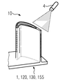
도 1 및 도 2는 본 발명에 따른 방법 및 장치의 진행 과정을 도시한 개략도이다.
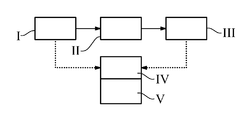
도 3은 방법의 진행 과정을 개략적으로 도시한 도면이다.
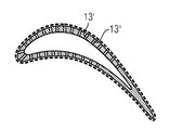
도 4는 층 두께 측정 위치를 도시한 단면도이다.
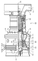
도 5는 가스 터빈을 도시한 도면이다.
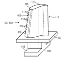
도 6은 터빈 블레이드를 도시한 도면이다.
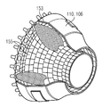
도 7은 연소실을 도시한 도면이다.
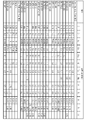
도 8은 초합금의 목록을 나타낸 도표이다.1 and 2 are schematic diagrams illustrating the progress of a method and apparatus according to the present invention.
3 is a diagram schematically illustrating a process of the method.
4 is a cross-sectional view showing the position of the layer thickness measurement.
5 shows a gas turbine.
6 shows a turbine blade.
7 shows a combustion chamber.
8 is a table showing a list of superalloys.
도면들과 설명은 본 발명의 실시예들만을 나타낸다.The drawings and description show only embodiments of the invention.
도 1에는 예시로서 이용되는 구조 부재(1)로서 터빈 블레이드(120, 130)가 도시되어 있다. 터빈 블레이드(120, 130)는 새 구조 부재일 수 있거나, 또는 이미 이용되었고, 예컨대 층 제거 공정에 의한 벽 두께 감소부를 보유하는 (재연마로부터) 층 제거된 구조 부재(120, 130)일 수 있다.1 shows
제1 단계에서 코팅 이전에 레이저 삼각 측정을 위한 센서(4)에 의해 블레이드(120, 130)는 층 두께의 검사가 의미가 있는 것으로 보이는 각각의 위치(13', 13")(도 4)에서 측정된다(도 3의 I). 이는 하나 이상의 지점에서 국소적으로 이루어질 수 있거나, 또는 코팅할 표면 전체에 걸쳐 전역에서 이루어질 수 있다.By the
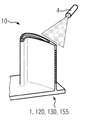
그런 후에 터빈 블레이드(120, 130)가 코팅되고(도 3의 II), 터빈 블레이드(120, 130)는 다시 레이저 삼각 측정에 의해 측정된다(도 2 또는 도 3의 III).The
레이저 삼각 측정을 이용한 측정은 바람직하게는 코팅(II) 도중에도 이루어질 수 있다.Measurements using laser triangulation can preferably be made during coating (II).
이에 따라 코팅 이전과 코팅 이후에, 또는 코팅 중에 획득된 데이터들은 컴퓨터(도 3의 IV)에 의해 서로 비교되고 이에 따라 각각의 목표하는 위치(도 4)에서 층 두께가 산출될 수 있고 바람직하게는 설정 값과 비교될 수 있다.The data obtained before and after coating or during coating are thus compared with each other by a computer (IV in FIG. 3) so that the layer thickness can be calculated at each target position (FIG. 4) and preferably Can be compared with the set value.
기하 구조 데이터들의 차이 계산을 통해 각각의 목표하는 위치(13', 13")(도 4)에서 층 두께가 결정된다(도 3의 V).The layer thickness is determined at each
층 두께는 금속 및 세라믹 층 용도로 형성될 수 있고 APS, VPS, PVP, CVD에 의해 결정될 수 있다.Layer thicknesses may be formed for metal and ceramic layer applications and may be determined by APS, VPS, PVP, CVD.
바람직하게는 측정은 사전 및 사후에 동일한 고정구에서, 바람직하게는 구조 부재(120, 130)의 조립 및 분해 없이 실행된다.Preferably the measurement is carried out before and after the same fixture, preferably without assembly and disassembly of the
바람직하게는 측정은 코팅 이전과 코팅 이후에만 실행되는데, 그 이유는 그럼으로써 기술적 구성이 다소 더욱 간단하기 때문이다.Preferably the measurement is carried out only before and after the coating, since the technical configuration is thus somewhat simpler.
바람직하게는 구조 부재가 광범위하게 스캐닝 되고, 터빈 블레이드(120, 130)의 경우는 터빈 베인 및 블레이드 플랫폼이 광범위하게 스캐닝 되는데, 그 이유는 특히 표면이 만곡된 경우 다양한 층 두께가 설정되기 때문이다.Preferably, the structural members are scanned extensively, in the case of
구조 부재(1, 120, 139, 155) 상에서, 특히 블레이드(120, 130)의 경우 기준점을 선택하는 것을 통해, 바람직하게는, 예컨대 [블레이드 기저부는 상당한 괴상체(massive)이기 때문에] 블레이드 기저부 상에서, 또는 고정구 상에서처럼 왜곡되지 않은 위치의 지점을 선택하는 것을 통해, 구조 부재(1, 120, 130, 155)의 왜곡률(distortion), 특히 코팅 공정(열)에 의해 발생하는 구조 부재, 즉 블레이드 베인의 훨씬 더 얇은 부분의 왜곡률이 고려될 수 있고, 실질적인 층 두께가 산출될 수 있다.On the
상기 공정은 높은 자동화율을 나타내며 공정 적격성 평가 동안 이용될 수 있거나, 또는 공정 수반 측정으로서, 또는 품질 관리로서 이용될 수 있다.The process exhibits a high degree of automation and can be used during process qualification, or can be used as a process accompanying measurement or as a quality control.
코팅 공정은 일반적으로 이루어지는, 요컨대 터빈 블레이드의 블레이드 베인처럼 국소적으로 이루어지는 재료 증착을 의미하거나, 블레이드 베인 상의 국소적 코팅이나, 완전한 코팅 공정, 또는 용접 코팅 방법도 의미한다.The coating process generally means locally deposited material, such as blade vanes of a turbine blade, or it also means a local coating on a blade vane, a complete coating process, or a welding coating method.
도 5에는 예시로서 가스 터빈(100)이 부분 종단면도로 도시되어 있다.In FIG. 5, the
가스 터빈(100)은 내부에, 회전축(102)을 중심으로 회전 가능하게 장착되고 샤프트를 구비한 회전자(103)를 포함하며, 회전자는 또한 터빈 회전자로서도 지칭된다. 회전자(103)를 따라서 흡기 하우징(104)과, 압축기(105)와, 동축으로 배치되는 복수의 버너(107)를 구비하는 예컨대 원환체형인 연소실(110), 특히 환형 연소실과, 터빈(108)과, 배기 하우징(109)이 연속해서 배치된다. 환형 연소실(110)은 예컨대 환형인 고온 가스 채널(111)과 연통된다. 상기 고온 가스 채널에서는 예컨대 연속해서 연결되는 4개의 터빈 단(112)(turbine stage)이 터빈(108)을 형성한다. 각각의 터빈 단(112)은 예컨대 2개의 블레이드 링으로 형성된다. 작동 매체(113)의 흐름 방향에서 볼 때, 고온 가스 채널(111) 내에서는 가이드 블레이드 열(115) 다음에, 회전 블레이드들(120)로 형성된 열(125)이 배치된다.The
이 경우, 가이드 블레이드들(130)은 고정자(143)의 내부 하우징(138)에 고정되며, 이에 반해서 열(125)의 회전 블레이드들(120)은 예컨대 터빈 디스크(133)에 의해 회전자(103)에 장착된다. 회전자(103)에는 발전기 또는 작업 기계(미도시)가 연결된다.In this case, the
가스 터빈(100)의 작동 중에 압축기(105)에 의해서는 흡기 하우징(104)을 통해 공기(135)가 흡입되어 압축된다. 압축기(105)의 터빈 측 단부에서 공급되는 압축된 공기는 버너들(107)로 안내되고 버너들에서 연료와 혼합된다. 그런 다음 혼합기는 연소실(110) 내에서 작동 매체(113)를 형성하면서 연소된다. 작동 매체(113)는 연소실로부터 고온 가스 채널(111)을 따라서 가이드 블레이드들(130) 및 회전 블레이드들(120)을 통과하여 흐른다. 회전 블레이드들(120)에서는 작동 매체(113)가 펄스를 전달하는 방식으로 팽창되며, 그럼으로써 회전 블레이드들(120)은 회전자(103)를 구동하고 회전자는 자체에 연결된 작업 기계를 구동한다.During operation of the
고온의 작동 매체(113)에 노출되는 구조 부재들은 가스 터빈(100)의 작동 중에 열적 부하를 받는다. 작동 매체(113)의 흐름 방향에서 볼 때 제1 터빈 단(112)의 가이드 블레이드들(130) 및 회전 블레이드들(120)은 환형 연소실(110)을 라이닝 하는 열차폐 부재들의 옆에서 열적 부하를 가장 많이 받는다. 이런 위치에서 존재하는 온도를 견디도록 하기 위해, 상기 블레이드들은 냉각제에 의해 냉각될 수 있다. 또한, 구조 부재의 기재들(substrates)은 방향성 구조를 포함할 수 있으며, 다시 말하면 기재들은 단결정성(SX 구조)이거나, 또는 종방향 입자(DS 구조)만을 포함한다. 구조 부재를 위한 재료로서, 특히 터빈 블레이드(120, 130)와, 연소실(110)의 구조 부재를 위한 재료로서는 예컨대 철 기반, 니켈 기반 또는 코발트 기반 초합금이 이용된다. 상기 초합금은 예컨대 EP 1 204 776 B1, EP 1 306 454, EP 1 319 729 A1, WO 99/67435 또는 WO 00/44949호로부터 공지되었다.Structural members exposed to the hot working
가이드 블레이드(130)는 터빈(108)의 내부 하우징(138)으로 향해 있는 가이드 블레이드 기저부(본원에서는 미도시)와, 가이드 블레이드 기저부와 마주보고 위치하는 가이드 블레이드 두부를 포함한다. 가이드 블레이드 두부는 회전자(103)로 향해 있으면서 고정자(143)의 고정 링(140)에 고정된다.The
도 6에는 종축(121)을 따라 연장되는 터빈식 기관의 회전 블레이드(120) 또는 가이드 블레이드(130)가 사시도로 도시되어 있다.6 shows a perspective view of a rotating
터빈식 기관은 비행기 또는 전기 생성용 발전소의 가스 터빈, 증기 터빈 또는 압축기일 수 있다.The turbine engine may be a gas turbine, steam turbine or compressor of an airplane or electricity generating plant.
블레이드(120, 130)는 종축(121)을 따라 연속적으로 고정 영역(400)과, 이 고정 영역에 인접하는 블레이드 플랫폼(403)뿐 아니라, 블레이드 베인(406)과, 블레이드 첨단(415)을 포함한다. 가이드 블레이드(130)로서 블레이드(130)는 자체의 블레이드 첨단(415)에 추가의 플랫폼을 포함할 수 있다(미도시).The
고정 영역(400)에는 샤프트 또는 디스크(미도시)에 회전 블레이드들(120, 130)을 고정하는 역할을 하는 블레이드 기저부(183)가 형성된다. 블레이드 기저부(183)는 예컨대 해머 헤드로서 구성된다. 전나무형 기저부나 제비 꼬리형 기저부로서 구성되는 또 다른 구현예도 가능하다. 블레이드(120, 130)는 블레이드 베인(406)을 통과하여 흐르는 매체를 위해 유입 에지(409) 및 유출 에지(412)를 포함한다.The
통상적인 블레이드들(120, 130)의 경우 블레이드(120, 130)의 모든 영역(400, 403, 406)에서는 예컨대 괴상의 금속 재료, 특히 초합금이 이용된다. 상기 초합금은 예컨대 EP 1 204 776 B1, EP 1 306 454, EP 1 319 729 A1, WO 99/67435 또는 WO 00/44949호로부터 공지되었다. 이 경우 블레이드(120, 130)는 주조 방법에 의해, 마찬가지로 방향성 응고를 이용한 주조 방법에 의해, 단조 방법에 의해, 밀링 방법에 의해, 또는 상기 방법들이 조합된 방법에 의해 제조될 수 있다.In the case of
단결정성 구조 또는 구조들을 보유하는 피가공재는 작동 시에 높은 기계적, 열적 및/또는 화학적 부하에 노출되는 기계를 위한 구조 부재로서 이용된다. 상기 유형의 단결정성 피가공재의 제조는 예컨대 용융물로부터 방향성 응고를 통해 이루어진다. 이는 액상 금속 합금이 단결정성 구조로, 다시 말하면 단결정성 피가공재로 응고되거나, 또는 방향성 응고되는 주조 방법이다.Workpieces having a monocrystalline structure or structures are used as structural members for machines that are exposed to high mechanical, thermal and / or chemical loads in operation. The production of monocrystalline workpieces of this type takes place, for example, via directional solidification from the melt. This is a casting method in which a liquid metal alloy is solidified in a monocrystalline structure, that is, in a monocrystalline workpiece, or directional solidified.
이 경우, 수지상 결정(dendritic crystal)은 열 흐름을 따라 배향되면서 주상 결정 입자 구조(주상, 즉 피가공재의 길이 전체에 걸쳐서 연장되고, 본원에서는 일반적인 표현에 따라 방향성 응고되는 것으로 지칭되는 입자)를 형성하거나, 또는 단결정 구조를 형성하며, 다시 말하면 전체의 피가공재가 단일 결정으로 구성된다. 이런 방법에서는 구상형(다결정) 응고로의 전환을 피해야만 하는데, 그 이유는 비방향성 성장에 의해 필연적으로 횡방향 및 종방향 결정 경계가 형성되고, 이들 결정 경계는 방향성 응고되거나 단결정인 구조 부재의 양호한 특성을 무산시키기 때문이다. 만일 일반적으로 문제의 대상이 방향성 응고된 구조라면, 이는 입자 경계를 갖지 않거나, 최대 소각립계(small-angle grain boundary)를 갖는 단결정뿐 아니라, 사실 종방향으로 연장되는 입자 경계를 갖긴 하지만 횡방향 입자 경계를 포함하지 않는 주상 결정 구조를 의미한다. 또한, 두 번째로 언급한 상기 결정 구조의 경우를 흔히 방향성 응고 구조(directionally solidified structures)라고도 한다. 상기 방법은 US-PS 6,024,792호와 EP 0 892 090 A1호로부터 공지되었다. 상기 공보들은 응고 방법과 관련하여 공지 기술의 일부이다.In this case, the dendritic crystals are oriented along the heat flow to form columnar crystal grain structures (particles which extend throughout the length of the columnar, ie, workpiece, referred to herein as directional solidified according to the general expression). Or form a single crystal structure, that is, the entire work piece consists of a single crystal. In this method, the transition to spherical (polycrystalline) coagulation should be avoided, because non-directional growth inevitably results in the formation of transverse and longitudinal crystalline boundaries, which are directional solidified or monocrystalline. This is because good characteristics are dissipated. If the subject in question is generally a directional solidified structure, it is a transverse particle that has no grain boundaries or single grains with maximum small-angle grain boundaries, but in fact longitudinal grain boundaries. It means columnar crystal structure without boundary. The second mentioned crystal structure is also often referred to as directionally solidified structures. The method is known from US Pat. No. 6,024,792 and EP 0 892 090 A1. These publications are part of the known art with regard to the solidification method.
또한, 블레이드들(120, 130)은 부식이나 산화에 대항하는 코팅층, 예컨대 MCrAlX 층을 포함할 수 있으며, MCrAlX에서 M은 철(Fe), 코발트(Co), 니켈(Ni)의 그룹 중 하나 이상의 원소이고, X는 능동 원소이면서 이트륨(Y) 및/또는 규소 및/또는 희토류 중 하나 이상의 원소 또는 하프늄(Hf)을 나타낸다. 상기 합금은 EP 0 486 489 B1, EP 0 786 017 B1, EP 0 412 397 B1 또는 EP 1 306 454 A1호로부터 공지되었다. 밀도는 바람직하게는 이론적인 밀도의 95%이다. (중간층으로서, 또는 최외부 층으로서의) MCrAlX 층 상에는 보호용 알루미늄 산화층(TGO = 열성장 산화층)이 형성된다.In addition, the
바람직하게는 층 조성은 Co-30Ni-28Cr-8Al-0,6Y-0,7Si 또는 Co-28Ni-24Cr-10Al-0,6Y를 함유한다. 이와 같은 코발트 기반 보호 코팅층 외에도 바람직하게는 Ni-10Cr-12Al-0,6Y-3Re 또는 Ni-12Co-21Cr-11Al-0,4Y-2Re 또는 Ni-25Co-17Cr-10Al-0,4Y-1,5Re와 같은 니켈 기반 보호층도 이용된다.Preferably the layer composition contains Co-30Ni-28Cr-8Al-0,6Y-0,7Si or Co-28Ni-24Cr-10Al-0,6Y. In addition to such a cobalt-based protective coating layer, preferably Ni-10Cr-12Al-0,6Y-3Re or Ni-12Co-21Cr-11Al-0,4Y-2Re or Ni-25Co-17Cr-10Al-0,4Y-1, Nickel-based protective layers such as 5Re are also used.
MCrAlX 상에는 단열층이 재차 제공될 수 있으며, 상기 단열층은 바람직하게는 최외부 층이고, 예컨대 ZrO2, Y2O3-ZrO2로 구성되며, 다시 말하면 상기 단열층은 산화 이트륨 및/또는 산화 칼슘 및/또는 산화 마그네슘에 의해 전혀 안정화되지 않거나, 부분적으로 또는 완전히 안정화된다. 단열층은 MCrAlX 층 전체를 덮는다. 예컨대 전자빔 증착(EB-PVD)과 같은 적합한 코팅 방법을 통해 단열층 내에 주상 입자들이 생성된다. 또 다른 코팅 방법, 예컨대 대기압 플라스마 용사(APS), LPPS, VPS 또는 CVD도 생각해볼 수 있다. 단열층은 보다 나은 내열충격성을 위한, 미세 균열 또는 거대 균열이 있는 다공성 입자들을 포함할 수 있다. 즉, 단열층은 바람직하게는 MCrAlX 층보다 더 다공성이다.And a heat insulating layer can be formed on some other time providing MCrAlX, wherein the heat insulating layer is preferably the outermost layer, such as ZrO 2, Y 2 O 3 -ZrO 2 is composed of, in other words the heat insulating layer is yttrium and / or calcium oxide and / Or not stabilized at all, or partially or fully, by magnesium oxide. The insulating layer covers the entire MCrAlX layer. Columnar particles are produced in the thermal insulation layer through suitable coating methods such as, for example, electron beam deposition (EB-PVD). Other coating methods can also be considered, such as atmospheric plasma spray (APS), LPPS, VPS or CVD. The thermal insulation layer may comprise porous particles with microcracks or macrocracks for better thermal shock resistance. That is, the thermal insulation layer is preferably more porous than the MCrAlX layer.
블레이드(120, 130)는 중공체 또는 괴상체로 형성될 수 있다. 블레이드(120, 130)가 냉각되어야 한다면, 블레이드는 중공체이고 경우에 따라 (파선으로 도시된) 막 냉각 구멍들(418)(film cooling hole)도 포함한다.The
도 7에는 가스 터빈(100)의 연소실(110)이 도시되어 있다. 연소실(110)은 예컨대 이른바 환형 연소실로서 구성되며, 이런 환형 연소실의 경우 회전축(102)의 둘레에 원주 방향으로 배치되는 복수의 버너(107)가 공동의 연소실 공간(154) 내로 통해 있으면서 불꽃(156)을 생성한다. 이를 위해 연소실(110)은 그 전체가 회전축(102)을 중심으로 배치되는 환형 구조로서 구성된다.7 shows the
비교적 높은 효율을 달성하기 위해 연소실(110)은 약 1000℃ 내지 1600℃의 작동 매체(M)의 비교적 높은 온도에 적합하게 설계된다. 또한, 작동 파라미터들이 재료에 대해 바람직하지 못한 경우에도 비교적 오랜 작동 시간을 가능하게 하기 위해, 연소실 벽부(153)는 작동 매체(M)로 향해 있는 자체의 측면에 열차폐 부재들(155)로 형성되는 내부 라이닝을 구비한다.In order to achieve a relatively high efficiency, the
또한, 연소실(110)의 내부에서 발생하는 높은 온도를 바탕으로, 차폐 부재들(155) 또는 이들 차폐 부재의 고정 부재들을 위해 냉각 시스템이 제공될 수 있다. 이런 경우 열차폐 부재들(155)은 예컨대 중공체이고, 경우에 따라 연소실 공간(154) 내로 통해 있는 냉각 구멍들(미도시)도 포함한다.In addition, a cooling system may be provided for the shielding
합금으로 이루어진 각각의 열차폐 부재(155)는 작동 매체 측에 특히 내열성이 강한 보호층(MCrAlX 층 및/또는 세라믹 코팅층)을 보유하거나, 또는 내고온성 재료(괴상 세라믹 스톤)으로 제조된다. 상기 보호층들은 터빈 블레이드와 유사할 수 있으며, 다시 말해 예컨대 MCrAlX를 의미하며, MCrAlX에서 M은 철(Fe), 코발트(Co), 니켈(Ni)의 그룹 중 하나 이상의 원소이고, X는 능동 원소이면서 이트륨(Y) 및/또는 규소 및/또는 희토류 중 하나 이상의 원소 또는 하프늄(Hf)을 나타낸다. 상기 합금은 EP 0 486 489 B1, EP 0 786 017 B1, EP 0 412 397 B1 또는 EP 1 306 454 A1호로부터 공지되었다.Each
MCrAlX 상에는 예컨대 세라믹 단열층이 제공될 수 있으며, 이런 단열층은 예컨대 ZrO2, Y2O3-ZrO2로 구성되며, 다시 말해 상기 단열층은 산화 이트륨 및/또는 산화 칼슘 및/또는 산화 마그네슘에 의해 안정화되지 않거나, 부분적으로 또는 완전히 안정화된다. 예컨대 전자빔 증착(EB-PVD)과 같은 적합한 코팅 방법을 통해 단열층 내에는 주상 입자들이 생성된다.For example, and a ceramic heat insulating layer may be provided formed on the MCrAlX, such a heat insulating layer, for example is composed of ZrO 2, Y 2 O 3 -ZrO 2, In other words, the heat insulating layer has been stabilized by yttrium oxide and / or calcium and / or magnesium oxide Or partially or fully stabilized. Columnar particles are produced in the thermal insulation layer through suitable coating methods such as, for example, electron beam deposition (EB-PVD).
또 다른 코팅 방법, 예컨대 대기압 플라스마 용사(APS), LPPS, VPS 또는 CVD도 생각해볼 수 있다. 단열층은 보다 나은 내열충격성을 위한, 미세 균열 또는 거대 균열이 있는 다공성 입자들을 포함할 수 있다.Other coating methods can also be considered, such as atmospheric plasma spray (APS), LPPS, VPS or CVD. The thermal insulation layer may comprise porous particles with microcracks or macrocracks for better thermal shock resistance.
재처리(재연마)는, 터빈 블레이드(120, 130) 또는 차폐 부재(155)가 이용된 후에 경우에 따라 상기 터빈 블레이드 또는 차폐 부재에서 보호층들이 (예컨대 모래 분사를 통해) 제거되어야 하는 것을 의미한다. 그런 후에 부식 및/또는 산화 층 또는 그 생성물의 제거가 이루어진다. 또한, 경우에 따라 터빈 블레이드(120, 130) 또는 차폐 부재(155) 내 균열이 수리된다. 그런 후에 터빈 블레이드(120, 130) 또는 차폐 부재(155)가 재코팅 되며, 그리고 터빈 블레이드(120, 130) 또는 차폐 부재(155)가 다시 이용된다.Reprocessing (regrinding) means that after the
Claims (9)
상기 장치는
구조 부재(1, 120, 130, 155)를 위한 고정구와,
구조 부재(1, 120, 130, 155)와,
레이저 삼각 측정을 위한 센서(4)와,
코팅(II) 이전에, 코팅 동안에, 또는 코팅 이후에 상기 구조 부재(1, 120, 130, 155)의 여러 측정치를 검출하여 상기 측정치들의 차이 계산(V)을 가능하게 함으로써 층 두께가 산출될 수 있게 하는 계산 유닛(IV)을 포함하고,
상기 고정구 또는 상기 구조 부재(1, 120, 130, 155)는 상기 구조 부재(1, 120, 130, 155)의 왜곡률을 측정하기 위한 기준점을 보유하는, 상기 층 두께 측정 방법을 실행하기 위한 장치.In particular the apparatus 10 for carrying out the method for measuring the layer thickness according to any one of the preceding claims,
The device
Fasteners for structural members 1, 120, 130, 155,
Structural members 1, 120, 130 and 155,
Sensor (4) for laser triangulation,
The layer thickness can be calculated by detecting several measurements of the structural members 1, 120, 130, 155 before coating (II), during or after coating to enable calculation of the difference (V) of the measurements. Includes a calculation unit (IV),
The fixture or the structural member (1, 120, 130, 155) has a reference point for measuring the distortion of the structural member (1, 120, 130, 155).
Applications Claiming Priority (2)
| Application Number | Priority Date | Filing Date | Title |
|---|---|---|---|
| EP09013170.7 | 2009-10-19 | ||
| EP09013170A EP2312267A1 (en) | 2009-10-19 | 2009-10-19 | Device and method for measuring thickness of coating with laser triangulation |
Publications (1)
| Publication Number | Publication Date |
|---|---|
| KR20120098632A true KR20120098632A (en) | 2012-09-05 |
Family
ID=41557637
Family Applications (1)
| Application Number | Title | Priority Date | Filing Date |
|---|---|---|---|
| KR1020127009905A KR20120098632A (en) | 2009-10-19 | 2010-06-21 | Method for measuring layer thickness by means of laser triangulation, and device |
Country Status (7)
| Country | Link |
|---|---|
| US (1) | US20120263866A1 (en) |
| EP (2) | EP2312267A1 (en) |
| JP (1) | JP2013508696A (en) |
| KR (1) | KR20120098632A (en) |
| CN (1) | CN102575927A (en) |
| RU (1) | RU2541440C2 (en) |
| WO (1) | WO2011047890A1 (en) |
Families Citing this family (7)
| Publication number | Priority date | Publication date | Assignee | Title |
|---|---|---|---|---|
| US9303983B2 (en) * | 2012-04-02 | 2016-04-05 | The Boeing Company | Sealant analysis system |
| DE102012217176A1 (en) | 2012-09-24 | 2014-03-27 | Evonik Litarion Gmbh | Method for aligning a laser sensor to a measured object |
| DE102012217175A1 (en) | 2012-09-24 | 2014-03-27 | Evonik Litarion Gmbh | Method for aligning two laser sensors to each other |
| CN103245291B (en) * | 2013-04-24 | 2015-12-09 | 中国船舶重工集团公司第十二研究所 | Blade parts assembly accuracy detection method |
| US9721044B2 (en) | 2013-05-10 | 2017-08-01 | General Electric Company | Systems and methods for non-destructive evaluation of molds and crucibles used in investment casting |
| DE102015217166A1 (en) * | 2015-09-09 | 2017-03-09 | Mtu Aero Engines Gmbh | Method for determining at least one surface property |
| GB201808325D0 (en) * | 2018-05-21 | 2018-07-11 | 3D Automated Metrology Inspection Ltd | Apparatus For Monitoring A Coating |
Family Cites Families (12)
| Publication number | Priority date | Publication date | Assignee | Title |
|---|---|---|---|---|
| US5013A (en) * | 1847-03-13 | Improvement in apparatus for the manufacture of malleable iron | ||
| US6024A (en) * | 1849-01-09 | Cast-iron gar-wheel | ||
| US10011A (en) * | 1853-09-13 | Improvement in the shape of scythes | ||
| US7027A (en) * | 1850-01-15 | Circulak | ||
| DE10313888A1 (en) * | 2003-03-27 | 2004-10-28 | Fraunhofer-Gesellschaft zur Förderung der angewandten Forschung e.V. | Continuous online measurement and regulation of the thickness of a coating to be applied to a technical workpiece uses a triangulation method with an optical sensor arrangement |
| US8315834B2 (en) * | 2003-12-17 | 2012-11-20 | Siemens Energy, Inc. | System and method for measuring coating thickness |
| EP1643209B1 (en) * | 2004-09-30 | 2020-11-04 | Ansaldo Energia IP UK Limited | Method for measuring a coating thickness |
| CA2605970A1 (en) * | 2005-04-29 | 2006-11-09 | National Research Council Of Canada | Method of on-line thickness measurement of applied coatings |
| EP1844892A1 (en) * | 2006-04-13 | 2007-10-17 | ALSTOM Technology Ltd | Method of laser removing of coating material from cooling holes of a turbine component |
| JP2008202969A (en) * | 2007-02-16 | 2008-09-04 | Toppan Printing Co Ltd | Film thickness measuring device and film thickness measuring method |
| RU82035U1 (en) * | 2008-08-28 | 2009-04-10 | Юрий Андреевич Сазонов | DEVICE FOR MEASURING THICKNESS OF MOVING FILM (OPTIONS) |
| US8031346B2 (en) * | 2008-10-31 | 2011-10-04 | Siemens Energy, Inc. | Coating evaluation process |
-
2009
- 2009-10-19 EP EP09013170A patent/EP2312267A1/en not_active Withdrawn
-
2010
- 2010-06-21 EP EP10728168A patent/EP2491338A1/en not_active Withdrawn
- 2010-06-21 RU RU2012120660/28A patent/RU2541440C2/en not_active IP Right Cessation
- 2010-06-21 US US13/502,381 patent/US20120263866A1/en not_active Abandoned
- 2010-06-21 WO PCT/EP2010/058722 patent/WO2011047890A1/en active Application Filing
- 2010-06-21 KR KR1020127009905A patent/KR20120098632A/en not_active Application Discontinuation
- 2010-06-21 CN CN2010800472248A patent/CN102575927A/en active Pending
- 2010-06-21 JP JP2012534593A patent/JP2013508696A/en active Pending
Also Published As
| Publication number | Publication date |
|---|---|
| JP2013508696A (en) | 2013-03-07 |
| CN102575927A (en) | 2012-07-11 |
| EP2312267A1 (en) | 2011-04-20 |
| US20120263866A1 (en) | 2012-10-18 |
| WO2011047890A1 (en) | 2011-04-28 |
| RU2541440C2 (en) | 2015-02-10 |
| EP2491338A1 (en) | 2012-08-29 |
| RU2012120660A (en) | 2013-11-27 |
Similar Documents
| Publication | Publication Date | Title |
|---|---|---|
| US8437010B2 (en) | Surface analysis for detecting closed holes, and device | |
| RU2490102C2 (en) | Method of welding and structural element | |
| KR20120098632A (en) | Method for measuring layer thickness by means of laser triangulation, and device | |
| US20110031226A1 (en) | Method for Welding Depending on a Preferred Direction of the Substrate | |
| US20130268107A1 (en) | Surface analysis for detecting closed holes and method for reopening | |
| US20120205355A1 (en) | Method for producing an asymmetric diffuser using different laser positions | |
| US20130115479A1 (en) | Porous ceramic coating system | |
| US9097127B2 (en) | Porous layer system having a porous inner layer | |
| US9421639B2 (en) | Component having weld seam and method for producing a weld seam | |
| JP2012140644A (en) | Masking material, masking layer, process for masking substrate, and process for coating substrate | |
| US20110143163A1 (en) | Method for the production of an optimized bonding agent layer by means of partial evaporation of the bonding agent layer, and a layer system | |
| JP2015536406A (en) | Modified surface around the hole | |
| US20160312622A1 (en) | Thermal barrier coating of a turbine blade | |
| US20110293431A1 (en) | Component having varying structures and method for production | |
| US8123105B2 (en) | Process for brazing wide gaps | |
| US20120099978A1 (en) | Turbine Component Having Easily Removable Protective Layer, Set of Turbine Components, a Turbine and a Method for Protecting a Turbine Component | |
| US20100288823A1 (en) | Application of Solder to Holes, Coating Processes and Small Solder Rods | |
| US20100224600A1 (en) | Two-step welding process | |
| US20110020127A1 (en) | Component Comprising Overlapping Weld Seams and Method for the Production Thereof | |
| US20110056919A1 (en) | Method for Fusing Curved Surfaces, and a Device | |
| US9957809B2 (en) | Modified interface around a hole | |
| US8616764B2 (en) | Method for testing a thermography apparatus, designed for carrying out a thermography method, for its correct operation, test component therefor and method for its production | |
| US10975463B2 (en) | Monitoring and control of a coating process on the basis of a heat distribution on the workpiece | |
| US20110062120A1 (en) | Device for welding using a process chamber and welding method | |
| US8689731B2 (en) | Apparatus and process for coating a component with aligning device |
Legal Events
| Date | Code | Title | Description |
|---|---|---|---|
| A201 | Request for examination | ||
| E902 | Notification of reason for refusal | ||
| E601 | Decision to refuse application |