JP2013508696A - Method and apparatus for measuring film thickness by laser triangulation - Google Patents
Method and apparatus for measuring film thickness by laser triangulation Download PDFInfo
- Publication number
- JP2013508696A JP2013508696A JP2012534593A JP2012534593A JP2013508696A JP 2013508696 A JP2013508696 A JP 2013508696A JP 2012534593 A JP2012534593 A JP 2012534593A JP 2012534593 A JP2012534593 A JP 2012534593A JP 2013508696 A JP2013508696 A JP 2013508696A
- Authority
- JP
- Japan
- Prior art keywords
- coating
- vane
- turbine
- film thickness
- blade
- Prior art date
- Legal status (The legal status is an assumption and is not a legal conclusion. Google has not performed a legal analysis and makes no representation as to the accuracy of the status listed.)
- Pending
Links
Images


Classifications
-
- G—PHYSICS
- G01—MEASURING; TESTING
- G01B—MEASURING LENGTH, THICKNESS OR SIMILAR LINEAR DIMENSIONS; MEASURING ANGLES; MEASURING AREAS; MEASURING IRREGULARITIES OF SURFACES OR CONTOURS
- G01B11/00—Measuring arrangements characterised by the use of optical techniques
- G01B11/02—Measuring arrangements characterised by the use of optical techniques for measuring length, width or thickness
- G01B11/06—Measuring arrangements characterised by the use of optical techniques for measuring length, width or thickness for measuring thickness ; e.g. of sheet material
- G01B11/0616—Measuring arrangements characterised by the use of optical techniques for measuring length, width or thickness for measuring thickness ; e.g. of sheet material of coating
- G01B11/0683—Measuring arrangements characterised by the use of optical techniques for measuring length, width or thickness for measuring thickness ; e.g. of sheet material of coating measurement during deposition or removal of the layer
Landscapes
- Physics & Mathematics (AREA)
- General Physics & Mathematics (AREA)
- Turbine Rotor Nozzle Sealing (AREA)
- Length Measuring Devices By Optical Means (AREA)
Abstract
部品のコーティング前後にレーザー三角測量の測定を行なうことによって、プロセスの監視が自動化される。 Process monitoring is automated by taking laser triangulation measurements before and after coating the part.
Description
本発明は、レーザー三角測量によって膜厚を測定するための方法および装置に関する。 The present invention relates to a method and apparatus for measuring film thickness by laser triangulation.
品質アセスメントおよびそれ以降の使用に向けて、コーティングされた部品が、そのすべての場所で必要な膜厚を達成していることは重要である。 For quality assessment and subsequent use, it is important that the coated parts achieve the required film thickness at all locations.
このことは、渦電流の測定方法などの既存の測定方法では確認不可能である。 This cannot be confirmed by existing measurement methods such as an eddy current measurement method.
破壊試験は、部品を後で使用することを不可能にし、パラメータの最適化に使用されうるにすぎない。 Destructive testing makes the part impossible to use later and can only be used for parameter optimization.
したがって、本発明の目的は上記の課題を解決することである。 Therefore, an object of the present invention is to solve the above problems.
本発明の目的は、請求項1に特許請求されている方法、および、請求項8に特許請求されている装置によって達成される。 The object of the invention is achieved by a method as claimed in claim 1 and by an apparatus as claimed in claim 8.
これらの図およびその説明は、本発明の例示的実施形態を示すにすぎない。 These figures and their description merely show exemplary embodiments of the invention.
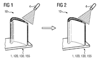
図1は、例として用いられる部品1として、タービンブレード120またはタービンベーン130を示す。
FIG. 1 shows a
タービンブレード120またはタービンベーン130は、新しい部品でもよく、または、(磨き直し(refurbishment)によって)被膜が取り除かれた、使用済みの、例として、被膜除去プロセスによって肉厚が減った部品120、130でもよい。
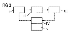
第1のステップでは、ブレード120またはベーン130は、コーティングの前に、膜厚を調べるのに都合のよいそれぞれの場所13'、13''(図4)で、レーザー三角測量の測定のためのセンサ4によって測定される(図3のI)。これは、1つまたは複数のポイントで局所的に行なわれてもよく、または、コーティングされる面全体にわたって全体的に行なわれてもよい。
In the first step, the
次に、タービンブレード120またはタービンベーン130は、コーティングされ(図3のII)、レーザー三角測量によって再度測定される(図2、および、図3のIII)。
The
好ましくは、レーザー三角測量による測定は、コーティング(II)の間に行なわれてもよい。 Preferably, measurement by laser triangulation may be performed during coating (II).
コーティング前後もしくはコーティング中にタービンブレード120またはタービンベーン130から得られたデータは、コンピュータによって互いに比較することができ(図3のIV)、それによって、それぞれの所望位置(図4)における膜厚が求められ、好ましくは、それらの膜厚が設定値と比較されうる。
Data obtained from
形状データの差を確定することによって、それぞれの所望位置13'、13''(図4)における膜厚が求められる(図3のV)。
By determining the difference in the shape data, the film thicknesses at the desired
膜厚は、金属層およびセラミック層に対してもたらされ、APS、VPS、PVD、CVDを用いて決めることができる。 Film thickness is provided for metal and ceramic layers and can be determined using APS, VPS, PVD, CVD.
測定は、好ましくは部品120、130の取り付けと取り外しをせずに、同じ取り付け台でコーティングの前後に行なわれることが好ましい。
Measurements are preferably made before and after coating on the same mounting base, preferably without attachment and removal of
この測定は、技術的準備がいくらか容易になることから、コーティングの前後だけで行なわれることが好ましい。 This measurement is preferably performed only before and after coating, since it makes the technical preparation somewhat easier.
タービンのメインブレードまたはベーン部分、および、ブレードプラットフォームまたはベーンプラットフォームからなるタービンブレード120またはタービンベーン130の場合、特に湾曲面では様々な膜厚が設定されているため、部品は、広範な範囲にわたってスキャンされることが好ましい。
In the case of
部品1、120、130、155の上に基準ポイントを選択することによって(特にブレード120またはベーン130の場合には、この基準ポイントは、非常に固いことによってブレードの付け根部分、もしくはベーンの付け根部分などの場所におけるポイント、または、取り付け台などの場所における変形することのないポイントであることが好ましい)、コーティングプロセス(熱)によって形成された部品1、120、130、155の変形、特に、具体的にはメインブレードまたはベーン部分である部品の非常に薄い部分における変形を考慮して、実際の膜厚を求めることができる。
By selecting a reference point on
このプロセスは、高度に自動化されており、プロセス認定の際に用いることができ、または、プロセスに付随する測定もしくは品質管理として用いることができる。 This process is highly automated and can be used during process qualification or as a measurement or quality control associated with the process.
概して、コーティングとは、物質を塗布することを意味し、狭義にはタービンブレードまたはタービンベーンにおけるメインブレードまたはベーン部分のように局所的に、メインブレードもしくはベーン部分の局所的なコーティングを意味するか、または全体的なコーティングを意味するが、さらに蒸着溶接プロセスも意味する。 In general, coating means applying a substance, or in a narrow sense, locally, like a main blade or vane part in a turbine blade or turbine vane, or a local coating on the main blade or vane part? Or an overall coating, but also an evaporation welding process.
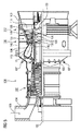
図5は、例として、ガスタービン100の部分的な縦方向の断面を示す。
FIG. 5 shows a partial longitudinal section of the
内部において、ガスタービン100は、回転軸102のまわりを回転できるように取り付けられた、タービンロータとも呼ばれる、シャフトをもつロータ103を有する。
Inside, the
このロータ103に沿って、吸気ハウジング104、コンプレッサ105、同軸上に配置された複数のバーナー107を有する、特に環状燃焼室である、例えばトロイダルの燃焼室110、タービン108、および排気ガスハウジング109が互いに続いている。
Along this
環状燃焼室110は、例えば、環状の高温ガス通路111と連通しており、この環状の高温ガス通路111では、例えば、連続した4つのタービン段112が、タービン108を形成している。
The
それぞれのタービン段112は、例えば2つのブレードリング、または2つのベーンリングから形成されている。作動媒体113が流れる方向に見られるように、高温ガス通路111では、ガイドベーンの並び115の後に、ロータブレード120から形成された並び125が続いている。
Each
ガイドベーン130は、ステータ143の内部ハウジング138に固定されており、並び125におけるロータブレード120は、例えばタービンディスク133によって、ロータ103に取り付けられている。
The
発電機(図示せず)は、ロータ103に結合している。
A generator (not shown) is coupled to the
ガスタービン100が動作する間、コンプレッサ105は、吸気ハウジング104を介して空気135を吸引し、その空気を圧縮する。コンプレッサ105のタービン側の端部で提供される圧縮された空気は、バーナー107に送られ、バーナー107で燃料と混ぜられる。次に、その混合物が燃焼室110で燃焼して、作動媒体113を発生させる。作動媒体113は、燃焼室110から、ガイドベーン130およびロータブレード120を通り過ぎて高温ガス通路111に沿って流れる。作動媒体113は、ロータブレード120の所で膨張して、作動媒体113の運動量を伝え、それによってロータブレード120はロータ103を駆動し、またロータ103は、ロータ103に結合している発電機を駆動する。
While the
ガスタービン100が動作する間、高温の作動媒体113にさらされる部品は熱応力を受ける。作動媒体113が流れる方向に見られる、第1のタービン段112におけるガイドベーン130およびロータブレード120、ならびに、環状燃焼室110の内側を覆う熱シールド素子は、最も強い熱応力を受ける。
While the
ガイドベーン130およびロータブレード120、ならびに熱シールド素子の所で生じる温度に耐えることができるように、ガイドベーン130およびロータブレード120、ならびに熱シールド素子は、冷却液によって冷却することができる。
The
さらに、これらの部品の基材は、方向性構造を有し、すなわち、単結晶形(SX構造)であるか、または、縦方向だけに配向した結晶粒を有する(DS構造)。 Furthermore, the base material of these parts has a directional structure, that is, a single crystal form (SX structure) or crystal grains oriented only in the longitudinal direction (DS structure).
例えば、特に、タービンブレード120またはタービンベーン130と、燃焼室110の部品とである部品の材料として、鉄基、ニッケル基、またはコバルト基の超合金が用いられる。
For example, iron-base, nickel-base, or cobalt-base superalloys are used, in particular, as materials for parts that are
このタイプの超合金は、例えば、EP 1 204 776 B1、EP 1 306 454、EP 1 319 729 A1、WO 99/67435、またはWO 00/44949より公知である。 Superalloys of this type are known, for example, from EP 1 204 776 B1, EP 1 306 454, EP 1 319 729 A1, WO 99/67435, or WO 00/44949.
ガイドベーン130は、タービン108の内部ハウジング138に対向するガイドベーンの付け根部分(図示せず)と、ガイドベーンの付け根部分の反対側の端にある、ガイドベーンの先端部分とを有する。ガイドベーンの先端部分は、ロータ103に対向しており、ステータ143の固定リング140に取り付けられている。
The
図6は、縦方向の軸121に沿って延びている、ターボ機械におけるロータブレード120またはガイドベーン130の斜視図を示す。
FIG. 6 shows a perspective view of a
このターボ機械は、飛行機もしくは発電所のガスタービン、蒸気タービン、またはコンプレッサでもよい。 The turbomachine may be an airplane or power plant gas turbine, steam turbine, or compressor.
ブレード120またはベーン130は、縦方向の軸121に沿って連続して、固定部400、隣接ブレードまたはベーンプラットフォーム403、メインブレードまたはベーン部分406、および、ブレード先端部またはベーン先端部415を有する。
The
ガイドベーン130として、ベーン130は、ベーン130のベーン先端部415の所にさらなるプラットフォーム(図示せず)を有する場合がある。
As
ロータブレード120、130をシャフトまたはディスク(図示せず)に固定するために用いられるブレードの付け根部分、またはベーンの付け根部分183は、固定部400に形成されている。
A root portion of a blade or a
ブレードの付け根部分、またはベーンの付け根部分183は、例えば、ハンマーの頭形(hammerhead form)で設計されている。もみの木形の付け根部分(fir-tree root)、または、あり継ぎの付け根部分(dovetail root)などの他の構成も可能である。
The base part of the blade or the
ブレード120またはベーン130は、メインブレードまたはベーン部分406のそばを通って流れる媒体のための前縁部409および後縁部412を有する。
従来のブレード120またはベーン130の場合、例えば、ブレード120またはベーン130のすべての部分400、403、406には、特に超合金である、中空でない金属材料が用いられる。
In the case of a
このタイプの超合金は、例えば、EP 1 204 776 B1、EP 1 306 454、EP 1 319 729 A1、WO 99/67435、またはWO 00/44949より公知である。 Superalloys of this type are known, for example, from EP 1 204 776 B1, EP 1 306 454, EP 1 319 729 A1, WO 99/67435, or WO 00/44949.
この場合、ブレード120またはベーン130は、鋳造プロセス、一方向性凝固、鍛造プロセス、切削プロセス、またはこれらの組み合わせによって作ることができる。
In this case, the
1つまたは複数の単結晶構造体を有する加工物は、運用時に強度の機械的応力、熱応力、および/または化学的応力を受ける、機械用の部品として用いられる。このタイプの単結晶の加工物は、溶融物からの一方向性凝固などによって作られる。これには、液体の金属合金が凝固して単結晶構造体、すなわち単結晶の加工物を形成する鋳造プロセス、または、液体の金属合金が一方向に凝固する鋳造プロセスが必要になる。 Workpieces having one or more single crystal structures are used as mechanical parts that are subjected to high mechanical, thermal and / or chemical stresses during operation. This type of single crystal workpiece is made, for example, by unidirectional solidification from a melt. This requires a casting process in which the liquid metal alloy solidifies to form a single crystal structure, ie, a single crystal workpiece, or a casting process in which the liquid metal alloy solidifies in one direction.
この場合、樹枝状結晶(dendritic crystals)は熱流の方向に沿って配向しており、柱状結晶粒子構造体(すなわち、加工物の長さ全体に及んでおり、慣例に従って用いられる言葉によって、本明細書では一方向に凝固したと呼ばれる結晶粒)か、または、加工物全体が単一の結晶からなる単結晶構造体のどちらかを形成する。これらのプロセスでは、全方向の(多結晶の)凝固への移行は避ける必要があるが、それは、一方向性凝固または単結晶の部品における好ましい特性を無効にする横方向と縦方向の結晶粒界を、方向性のない成長が必然的に形成するためである。 In this case, the dendritic crystals are oriented along the direction of heat flow and span the entire length of the columnar crystal grain structure (i.e., the length of the work piece, and the terminology used herein is Either the crystal grains that are solidified in one direction in the book) or the entire workpiece forms a single crystal structure consisting of a single crystal. In these processes, the transition to omnidirectional (polycrystalline) solidification has to be avoided, but it can be achieved by transverse and longitudinal grains that negate favorable properties in unidirectional solidification or single crystal parts. This is because growth with no directionality inevitably forms the field.
本明細書では、広義の用語として、一方向に凝固した微細構造体に言及する場合には、いかなる結晶粒界も有さないか、もしくは、せいぜい小角粒界を有する単結晶と、縦方向に及ぶ結晶粒界を有するが、いかなる横方向の結晶粒界も有さない柱状結晶構造体との両方を意味するものとして理解されるべきである。結晶構造体におけるこの第2の形態も、一方向に凝固した微細構造体(一方向に凝固した構造体)という言葉で記述される。 In this specification, as a broad term, when referring to a microstructure solidified in one direction, a single crystal having no grain boundary or having a small-angle grain boundary at most, and a longitudinal direction, It should be understood to mean both columnar crystal structures with a range of grain boundaries but without any lateral grain boundaries. This second form of the crystal structure is also described in terms of a fine structure solidified in one direction (a structure solidified in one direction).
このタイプのプロセスは、US-A 6,024,792およびEP 0 892 090 A1より公知であり、これらの文献は、凝固プロセスに関する本開示の一部をなしている。 This type of process is known from US-A 6,024,792 and EP 0 892 090 A1, which are part of the present disclosure relating to the coagulation process.
さらに、ブレード120またはベーン130は、MCrAlX(Mは、鉄(Fe)、コバルト(Co)、ニッケル(Ni)からなる群から選ばれた少なくとも1つの元素であり、Xは、活性元素であり、イットリウム(Y)、および/または、シリコン、および/または、少なくとも1つの希土類元素、またはハフニウム(Hf)を表す)などの、腐食または酸化から保護する被膜を有することができる。このタイプの合金は、EP 0 486 489 B1、EP 0 786 017 B1、EP 0 412 397 B1、またはEP 1 306 454 A1より公知である。
Further, the
密度は、理論密度である95%であることが好ましい。 The density is preferably 95% which is a theoretical density.
(中間層または最外層として)MCrAlX層の上には、保護用酸化アルミニウム層(TGO=熱成長酸化物層)が形成される。 A protective aluminum oxide layer (TGO = thermally grown oxide layer) is formed on the MCrAlX layer (as an intermediate layer or outermost layer).
MCrAlX層は、Co-30Ni-28Cr-8Al-0.6Y-0.7Si、または、Co-28Ni-24Cr-10Al-0.6Yの組成を有することが好ましい。これらのコバルト基の保護被膜に加えて、Ni-10Cr-12Al-0.6Y-3Re、または、Ni-12Co-21Cr-11Al-0.4Y-2Re、または、Ni-25Co-17Cr-10Al-0.4Y-1.5Reなどのニッケル基の保護層を使用することも好ましい。 The MCrAlX layer preferably has a composition of Co-30Ni-28Cr-8Al-0.6Y-0.7Si or Co-28Ni-24Cr-10Al-0.6Y. In addition to these cobalt-based protective coatings, Ni-10Cr-12Al-0.6Y-3Re or Ni-12Co-21Cr-11Al-0.4Y-2Re or Ni-25Co-17Cr-10Al-0.4Y- It is also preferable to use a nickel-based protective layer such as 1.5Re.
さらに、好ましくは最外層であり、例えばZrO2、Y2O3-ZrO2からなる断熱被膜であって、安定化されていないか、酸化イットリウムおよび/または酸化カルシウムおよび/または酸化マグネシウムによって部分的に安定化されているか、または完全に安定化された断熱被膜が、MCrAlXの上に設けられてもよい。 Furthermore, it is preferably the outermost layer, for example a thermal barrier coating made of ZrO 2 , Y 2 O 3 —ZrO 2, which is not stabilized or partially by yttrium oxide and / or calcium oxide and / or magnesium oxide A stabilized or fully stabilized thermal barrier coating may be provided on the MCrAlX.
この断熱被膜は、MCrAlX層全体を覆う。断熱被膜には、例えば電子ビーム物理蒸着法(EB-PVD)などの好適なコーティングプロセスによって柱状結晶粒が作られている。 This thermal barrier coating covers the entire MCrAlX layer. In the heat insulating coating, columnar crystal grains are formed by a suitable coating process such as electron beam physical vapor deposition (EB-PVD).
大気圧プラズマ溶射法(APS)、LPPS、VPS、またはCVDなどの他のコーティングプロセスも可能である。断熱被膜は、熱衝撃に対する耐性を改善するために、多孔性の、または、微視的なクラックもしくは巨視的なクラックを有する結晶粒を含むことができる。したがって、断熱被膜は、MCrAlX層より多孔性であることが好ましい。 Other coating processes such as atmospheric pressure plasma spraying (APS), LPPS, VPS, or CVD are possible. The thermal barrier coating can include crystal grains that are porous or have microscopic or macroscopic cracks to improve resistance to thermal shock. Therefore, it is preferable that the heat insulating coating is more porous than the MCrAlX layer.
ブレード120またはベーン130は、形状において中空であってもよく、また中空でなくてもよい。ブレード120またはベーン130が冷却される場合には、ブレード120またはベーン130は中空であり、(破線によって示されている)被膜冷却穴418を有することもできる。
図7は、ガスタービン100の燃焼室110を示す。この燃焼室110は、例えば、炎156を発生させ、回転軸102のまわりに円周方向に配置された複数のバーナー107が共通の燃焼室空間154に向けて開く、環状燃焼室として知られている、燃焼室として構成されている。このため、燃焼室110は、全体的に、回転軸102の周りに配置された環状構成となる。
FIG. 7 shows the
燃焼室110は、比較的高い効率を達成するために、約1000℃から約1600℃の作動媒体Mにおける比較的高い温度に合わせて設計されている。材料にとって好ましくないこれらの動作パラメータの場合でも比較的長い耐用年数を可能とするために、燃焼室壁153には、作動媒体Mに面する側に、熱シールド素子155から形成された内張りが設けられている。
The
さらに、燃焼室110の内部における高い温度を考慮して、熱シールド素子155、および/または、熱シールド素子155の保持素子のための冷却システムが設けられてもよい。さらに、例えば、熱シールド素子155は中空であり、燃焼室空間154に向かって開いている冷却孔(図示せず)を有することもできる。
Further, in view of the high temperature inside the
合金からなるそれぞれの熱シールド素子155は、特に耐熱性のある保護層(MCrAlX層および/またはセラミック被膜)を作動媒体の側に備えているか、または、高温に耐えることができる材料(中空でないセラミックれんが)から作られる。
Each heat-shielding
これらの保護層は、タービンブレードまたはタービンベーンと同様であってもよく、すなわち、例えばMCrAlXでもよい。ここで、Mは、鉄(Fe)、コバルト(Co)、ニッケル(Ni)からなる群から選ばれた少なくとも1つの元素であり、Xは、活性元素であり、イットリウム(Y)、および/または、シリコン、および/または、少なくとも1つの希土類元素、またはハフニウム(Hf)を表す。このタイプの合金は、EP 0 486 489 B1、EP 0 786 017 B1、EP 0 412 397 B1、またはEP 1 306 454 A1より公知である。 These protective layers may be similar to turbine blades or turbine vanes, i.e. for example MCrAlX. Here, M is at least one element selected from the group consisting of iron (Fe), cobalt (Co), nickel (Ni), X is an active element, yttrium (Y), and / or , Silicon and / or at least one rare earth element or hafnium (Hf). Alloys of this type are known from EP 0 486 489 B1, EP 0 786 017 B1, EP 0 412 397 B1, or EP 1 306 454 A1.
さらに、例えばZrO2、Y2O3-ZrO2からなる、例えばセラミックの、断熱被膜であって、安定化されていないか、酸化イットリウムおよび/または酸化カルシウムおよび/または酸化マグネシウムによって部分的に安定化されているか、または、完全に安定化された断熱被膜が、MCrAlXの上に設けられてもよい。 Furthermore, it is a thermal barrier coating, for example made of ZrO 2 , Y 2 O 3 -ZrO 2 , for example ceramic, which is not stabilized or partially stabilized by yttrium oxide and / or calcium oxide and / or magnesium oxide An insulated or fully stabilized thermal barrier coating may be provided on MCrAlX.
断熱被膜には、例えば電子ビーム物理蒸着法(EB-PVD)などの好適なコーティングプロセスによって柱状結晶粒が作られている。 In the heat insulating coating, columnar crystal grains are formed by a suitable coating process such as electron beam physical vapor deposition (EB-PVD).
大気圧プラズマ溶射法(APS)、LPPS、VPS、またはCVDなどの他のコーティングプロセスも可能である。断熱被膜は、熱衝撃に対する耐性を改善するために、多孔性の、または、微視的なクラックもしくは巨視的なクラックを有する結晶粒を含むことができる。 Other coating processes such as atmospheric pressure plasma spraying (APS), LPPS, VPS, or CVD are possible. The thermal barrier coating can include crystal grains that are porous or have microscopic or macroscopic cracks to improve resistance to thermal shock.
磨き直しは、保護層が使用された後に、その保護層がタービンブレード120またはタービンベーン130または熱シールド素子155から(例えば、サンドブラストによって)取り除かれる必要がありうることを意味する。次に、腐食層および/または酸化層および生成物が取り除かれる。さらに、タービンブレード120またはタービンベーン130または熱シールド素子155におけるクラックが適宜修復される。タービンブレード120またはタービンベーン130または熱シールド素子155の再コーティングがこれに続き、その後、タービンブレード120またはタービンベーン130または熱シールド素子155を再利用することができる。
Refurbishing means that after a protective layer has been used, it may need to be removed from
1 部品
4 センサ
10 装置
13' 位置
13'' 位置
100 ガスタービン
102 回転軸
103 ロータ
104 吸気ハウジング
105 コンプレッサ
107 バーナー
108 タービン
109 排気ガスハウジング
110 燃焼室
111 高温ガス通路
112 タービン段
113 作動媒体
115 ガイドベーンの並び
120 タービンブレード
125 ロータブレードから形成されている並び
130 タービンベーン
133 タービンディスク
135 空気
138 内部ハウジング
140 固定リング
143 ステータ
153 燃焼室壁
155 熱シールド素子
183 ブレードの付け根部分、またはベーンの付け根部分
400 固定部
403 隣接ブレードまたはベーンプラットフォーム
406 メインブレードまたはベーン部分
409 前縁部
412 後縁部
415 ブレード先端部またはベーン先端部
418 被膜冷却穴
I 膜厚を調べるためにタービンブレード120またはタービンベーン130が測定される。
II タービンブレード120またはタービンベーン130がコーティングされる。
III タービンブレード120またはタービンベーン130が再度測定される。
IV タービンブレード120またはタービンベーン130から得られたデータが比較される。
V 膜厚が求められる。
1 parts
4 Sensor
10 Equipment
13 'position
13 '' position
100 gas turbine
102 Rotation axis
103 rotor
104 Air intake housing
105 Compressor
107 burner
108 turbine
109 Exhaust gas housing
110 Combustion chamber
111 Hot gas passage
112 Turbine stage
113 Working medium
115 Arrangement of guide vanes
120 Turbine blade
125 Lines formed from rotor blades
130 Turbine vane
133 Turbine disc
135 Air
138 Internal housing
140 Retaining ring
143 Stator
153 Combustion chamber wall
155 Heat shield element
183 Blade root or vane root
400 fixed part
403 Adjacent blade or vane platform
406 Main blade or vane part
409 Front edge
412 Trailing edge
415 Blade tip or vane tip
418 Film cooling hole
The data obtained from the
V Thickness is required.
Claims (8)
前記部品(1、120、130、155)が、コーティングの前(I)、および、コーティング中(II)またはコーティングの後(III)にレーザー三角測量によって測定され、
前記部品(1、120、130、155)の様々な測定値から膜厚が計算され(V)、このうち、前記部品(1、120、130、155)の変形が考慮され、ブレードまたはベーン(120、130)の前記変形を求めるために、前記部品(1、120、130、155)に対する少なくとも1つの基準ポイントが用いられる、方法。 A method for determining the film thickness of a part to be coated (1, 120, 130, 155),
Said part (1, 120, 130, 155) is measured by laser triangulation before coating (I) and during coating (II) or after coating (III),
The film thickness is calculated from various measurements of the part (1, 120, 130, 155) (V), of which the deformation of the part (1, 120, 130, 155) is taken into account, the blade or vane ( A method in which at least one reference point for the part (1, 120, 130, 155) is used to determine the deformation of 120, 130).
部品(1、120、130、155)のための取り付け台と、
部品(1、120、130、155)と、
レーザー三角測量の測定のためのセンサ(4)と、
コーティング(II)の前、コーティング(II)中、またはコーティング(II)の後に前記部品(1、120、130、155)の様々な測定値を取得し、前記測定値の差を確定する(V)ことを可能にし、それによって膜厚が求められる、計算部(IV)と、
を備え、
前記取り付け台または前記部品(1、120、130、155)が、前記部品(1、120、130、155)の変形を求めるための基準ポイントを有する、装置(10)。 In particular, an apparatus (10) for carrying out the method claimed in claim 1, 2, 3, 4, 5, 6, or 7, comprising:
A mounting base for the parts (1, 120, 130, 155);
Parts (1, 120, 130, 155),
A sensor (4) for measuring laser triangulation,
Take various measurements of the part (1, 120, 130, 155) before coating (II), during coating (II) or after coating (II) and determine the difference between the measurements (V ), Thereby calculating the film thickness, and the calculation unit (IV),
With
The apparatus (10), wherein the mount or part (1, 120, 130, 155) has a reference point for determining deformation of the part (1, 120, 130, 155).
Applications Claiming Priority (3)
| Application Number | Priority Date | Filing Date | Title |
|---|---|---|---|
| EP09013170.7 | 2009-10-19 | ||
| EP09013170A EP2312267A1 (en) | 2009-10-19 | 2009-10-19 | Device and method for measuring thickness of coating with laser triangulation |
| PCT/EP2010/058722 WO2011047890A1 (en) | 2009-10-19 | 2010-06-21 | Method for measuring layer thickness by means of laser triangulation, and device |
Publications (2)
| Publication Number | Publication Date |
|---|---|
| JP2013508696A true JP2013508696A (en) | 2013-03-07 |
| JP2013508696A5 JP2013508696A5 (en) | 2013-11-14 |
Family
ID=41557637
Family Applications (1)
| Application Number | Title | Priority Date | Filing Date |
|---|---|---|---|
| JP2012534593A Pending JP2013508696A (en) | 2009-10-19 | 2010-06-21 | Method and apparatus for measuring film thickness by laser triangulation |
Country Status (7)
| Country | Link |
|---|---|
| US (1) | US20120263866A1 (en) |
| EP (2) | EP2312267A1 (en) |
| JP (1) | JP2013508696A (en) |
| KR (1) | KR20120098632A (en) |
| CN (1) | CN102575927A (en) |
| RU (1) | RU2541440C2 (en) |
| WO (1) | WO2011047890A1 (en) |
Families Citing this family (8)
| Publication number | Priority date | Publication date | Assignee | Title |
|---|---|---|---|---|
| US9303983B2 (en) * | 2012-04-02 | 2016-04-05 | The Boeing Company | Sealant analysis system |
| DE102012217176A1 (en) | 2012-09-24 | 2014-03-27 | Evonik Litarion Gmbh | Method for aligning a laser sensor to a measured object |
| DE102012217175A1 (en) | 2012-09-24 | 2014-03-27 | Evonik Litarion Gmbh | Method for aligning two laser sensors to each other |
| CN103245291B (en) * | 2013-04-24 | 2015-12-09 | 中国船舶重工集团公司第十二研究所 | Blade parts assembly accuracy detection method |
| US9721044B2 (en) | 2013-05-10 | 2017-08-01 | General Electric Company | Systems and methods for non-destructive evaluation of molds and crucibles used in investment casting |
| DE102015217166A1 (en) * | 2015-09-09 | 2017-03-09 | Mtu Aero Engines Gmbh | Method for determining at least one surface property |
| NL2016652B1 (en) | 2016-04-21 | 2017-11-16 | Innovative Mechanical Engineering Tech B V | Electrospinning device and method. |
| GB201808325D0 (en) * | 2018-05-21 | 2018-07-11 | 3D Automated Metrology Inspection Ltd | Apparatus For Monitoring A Coating |
Citations (5)
| Publication number | Priority date | Publication date | Assignee | Title |
|---|---|---|---|---|
| US5013A (en) * | 1847-03-13 | Improvement in apparatus for the manufacture of malleable iron | ||
| US6024A (en) * | 1849-01-09 | Cast-iron gar-wheel | ||
| US7027A (en) * | 1850-01-15 | Circulak | ||
| US10011A (en) * | 1853-09-13 | Improvement in the shape of scythes | ||
| JP2008202969A (en) * | 2007-02-16 | 2008-09-04 | Toppan Printing Co Ltd | Film thickness measuring device and film thickness measuring method |
Family Cites Families (7)
| Publication number | Priority date | Publication date | Assignee | Title |
|---|---|---|---|---|
| DE10313888A1 (en) * | 2003-03-27 | 2004-10-28 | Fraunhofer-Gesellschaft zur Förderung der angewandten Forschung e.V. | Continuous online measurement and regulation of the thickness of a coating to be applied to a technical workpiece uses a triangulation method with an optical sensor arrangement |
| US8315834B2 (en) * | 2003-12-17 | 2012-11-20 | Siemens Energy, Inc. | System and method for measuring coating thickness |
| EP1643209B1 (en) * | 2004-09-30 | 2020-11-04 | Ansaldo Energia IP UK Limited | Method for measuring a coating thickness |
| CA2605970A1 (en) * | 2005-04-29 | 2006-11-09 | National Research Council Of Canada | Method of on-line thickness measurement of applied coatings |
| EP1844892A1 (en) * | 2006-04-13 | 2007-10-17 | ALSTOM Technology Ltd | Method of laser removing of coating material from cooling holes of a turbine component |
| RU82035U1 (en) * | 2008-08-28 | 2009-04-10 | Юрий Андреевич Сазонов | DEVICE FOR MEASURING THICKNESS OF MOVING FILM (OPTIONS) |
| US8031346B2 (en) * | 2008-10-31 | 2011-10-04 | Siemens Energy, Inc. | Coating evaluation process |
-
2009
- 2009-10-19 EP EP09013170A patent/EP2312267A1/en not_active Withdrawn
-
2010
- 2010-06-21 US US13/502,381 patent/US20120263866A1/en not_active Abandoned
- 2010-06-21 WO PCT/EP2010/058722 patent/WO2011047890A1/en active Application Filing
- 2010-06-21 JP JP2012534593A patent/JP2013508696A/en active Pending
- 2010-06-21 KR KR1020127009905A patent/KR20120098632A/en not_active Application Discontinuation
- 2010-06-21 EP EP10728168A patent/EP2491338A1/en not_active Withdrawn
- 2010-06-21 CN CN2010800472248A patent/CN102575927A/en active Pending
- 2010-06-21 RU RU2012120660/28A patent/RU2541440C2/en not_active IP Right Cessation
Patent Citations (5)
| Publication number | Priority date | Publication date | Assignee | Title |
|---|---|---|---|---|
| US5013A (en) * | 1847-03-13 | Improvement in apparatus for the manufacture of malleable iron | ||
| US6024A (en) * | 1849-01-09 | Cast-iron gar-wheel | ||
| US7027A (en) * | 1850-01-15 | Circulak | ||
| US10011A (en) * | 1853-09-13 | Improvement in the shape of scythes | ||
| JP2008202969A (en) * | 2007-02-16 | 2008-09-04 | Toppan Printing Co Ltd | Film thickness measuring device and film thickness measuring method |
Also Published As
| Publication number | Publication date |
|---|---|
| EP2491338A1 (en) | 2012-08-29 |
| CN102575927A (en) | 2012-07-11 |
| KR20120098632A (en) | 2012-09-05 |
| WO2011047890A1 (en) | 2011-04-28 |
| EP2312267A1 (en) | 2011-04-20 |
| US20120263866A1 (en) | 2012-10-18 |
| RU2541440C2 (en) | 2015-02-10 |
| RU2012120660A (en) | 2013-11-27 |
Similar Documents
| Publication | Publication Date | Title |
|---|---|---|
| US8437010B2 (en) | Surface analysis for detecting closed holes, and device | |
| JP2013508696A (en) | Method and apparatus for measuring film thickness by laser triangulation | |
| US8847106B2 (en) | Welding process with a controlled temperature profile and a device therefor | |
| US20130115479A1 (en) | Porous ceramic coating system | |
| US10465535B2 (en) | Compressor blade or vane having an erosion-resistant hard material coating | |
| US20130268107A1 (en) | Surface analysis for detecting closed holes and method for reopening | |
| US20110135947A1 (en) | Masking Material, Masking Layer, Process for Masking a Substrate and Process for Coating a Substrate | |
| US9421639B2 (en) | Component having weld seam and method for producing a weld seam | |
| US20110143163A1 (en) | Method for the production of an optimized bonding agent layer by means of partial evaporation of the bonding agent layer, and a layer system | |
| US20130156966A1 (en) | Method for reprocessing a turbine blade having at least one platform | |
| US20160281511A1 (en) | Modified surface around a hole | |
| US20160312622A1 (en) | Thermal barrier coating of a turbine blade | |
| US20110020127A1 (en) | Component Comprising Overlapping Weld Seams and Method for the Production Thereof | |
| US20100288823A1 (en) | Application of Solder to Holes, Coating Processes and Small Solder Rods | |
| US8123105B2 (en) | Process for brazing wide gaps | |
| US20100224600A1 (en) | Two-step welding process | |
| US20120027931A1 (en) | Coating Having Thermal and Non-Thermal Coating Method | |
| US20110056919A1 (en) | Method for Fusing Curved Surfaces, and a Device | |
| US20160024941A1 (en) | Porous ceramic layer system | |
| US9957809B2 (en) | Modified interface around a hole | |
| US8616764B2 (en) | Method for testing a thermography apparatus, designed for carrying out a thermography method, for its correct operation, test component therefor and method for its production | |
| US10975463B2 (en) | Monitoring and control of a coating process on the basis of a heat distribution on the workpiece | |
| US20110062120A1 (en) | Device for welding using a process chamber and welding method | |
| US8689731B2 (en) | Apparatus and process for coating a component with aligning device | |
| US9212904B2 (en) | Device and method for passage measurement |
Legal Events
| Date | Code | Title | Description |
|---|---|---|---|
| A977 | Report on retrieval |
Free format text: JAPANESE INTERMEDIATE CODE: A971007 Effective date: 20130516 |
|
| A131 | Notification of reasons for refusal |
Free format text: JAPANESE INTERMEDIATE CODE: A131 Effective date: 20130521 |
|
| A601 | Written request for extension of time |
Free format text: JAPANESE INTERMEDIATE CODE: A601 Effective date: 20130820 |
|
| A602 | Written permission of extension of time |
Free format text: JAPANESE INTERMEDIATE CODE: A602 Effective date: 20130827 |
|
| A524 | Written submission of copy of amendment under section 19 (pct) |
Free format text: JAPANESE INTERMEDIATE CODE: A524 Effective date: 20130924 |
|
| A02 | Decision of refusal |
Free format text: JAPANESE INTERMEDIATE CODE: A02 Effective date: 20141117 |