KR20120074746A - Air circulation having illumination and sterilization ability - Google Patents
Air circulation having illumination and sterilization ability Download PDFInfo
- Publication number
- KR20120074746A KR20120074746A KR1020100136682A KR20100136682A KR20120074746A KR 20120074746 A KR20120074746 A KR 20120074746A KR 1020100136682 A KR1020100136682 A KR 1020100136682A KR 20100136682 A KR20100136682 A KR 20100136682A KR 20120074746 A KR20120074746 A KR 20120074746A
- Authority
- KR
- South Korea
- Prior art keywords
- housing
- air
- light
- fan
- led
- Prior art date
Links
Images


Classifications
-
- F—MECHANICAL ENGINEERING; LIGHTING; HEATING; WEAPONS; BLASTING
- F24—HEATING; RANGES; VENTILATING
- F24F—AIR-CONDITIONING; AIR-HUMIDIFICATION; VENTILATION; USE OF AIR CURRENTS FOR SCREENING
- F24F7/00—Ventilation
- F24F7/003—Ventilation in combination with air cleaning
-
- F—MECHANICAL ENGINEERING; LIGHTING; HEATING; WEAPONS; BLASTING
- F24—HEATING; RANGES; VENTILATING
- F24F—AIR-CONDITIONING; AIR-HUMIDIFICATION; VENTILATION; USE OF AIR CURRENTS FOR SCREENING
- F24F13/00—Details common to, or for air-conditioning, air-humidification, ventilation or use of air currents for screening
- F24F13/02—Ducting arrangements
- F24F13/06—Outlets for directing or distributing air into rooms or spaces, e.g. ceiling air diffuser
- F24F13/078—Outlets for directing or distributing air into rooms or spaces, e.g. ceiling air diffuser combined with lighting fixtures
-
- F—MECHANICAL ENGINEERING; LIGHTING; HEATING; WEAPONS; BLASTING
- F24—HEATING; RANGES; VENTILATING
- F24F—AIR-CONDITIONING; AIR-HUMIDIFICATION; VENTILATION; USE OF AIR CURRENTS FOR SCREENING
- F24F7/00—Ventilation
- F24F7/04—Ventilation with ducting systems, e.g. by double walls; with natural circulation
- F24F7/06—Ventilation with ducting systems, e.g. by double walls; with natural circulation with forced air circulation, e.g. by fan positioning of a ventilator in or against a conduit
- F24F7/10—Ventilation with ducting systems, e.g. by double walls; with natural circulation with forced air circulation, e.g. by fan positioning of a ventilator in or against a conduit with air supply, or exhaust, through perforated wall, floor or ceiling
-
- F—MECHANICAL ENGINEERING; LIGHTING; HEATING; WEAPONS; BLASTING
- F24—HEATING; RANGES; VENTILATING
- F24F—AIR-CONDITIONING; AIR-HUMIDIFICATION; VENTILATION; USE OF AIR CURRENTS FOR SCREENING
- F24F8/00—Treatment, e.g. purification, of air supplied to human living or working spaces otherwise than by heating, cooling, humidifying or drying
- F24F8/20—Treatment, e.g. purification, of air supplied to human living or working spaces otherwise than by heating, cooling, humidifying or drying by sterilisation
- F24F8/22—Treatment, e.g. purification, of air supplied to human living or working spaces otherwise than by heating, cooling, humidifying or drying by sterilisation using UV light
-
- Y—GENERAL TAGGING OF NEW TECHNOLOGICAL DEVELOPMENTS; GENERAL TAGGING OF CROSS-SECTIONAL TECHNOLOGIES SPANNING OVER SEVERAL SECTIONS OF THE IPC; TECHNICAL SUBJECTS COVERED BY FORMER USPC CROSS-REFERENCE ART COLLECTIONS [XRACs] AND DIGESTS
- Y02—TECHNOLOGIES OR APPLICATIONS FOR MITIGATION OR ADAPTATION AGAINST CLIMATE CHANGE
- Y02A—TECHNOLOGIES FOR ADAPTATION TO CLIMATE CHANGE
- Y02A50/00—TECHNOLOGIES FOR ADAPTATION TO CLIMATE CHANGE in human health protection, e.g. against extreme weather
- Y02A50/20—Air quality improvement or preservation, e.g. vehicle emission control or emission reduction by using catalytic converters
Abstract
Description
본 발명은 조명 및 살균 기능을 갖는 공기 흡배기 장치에 관한 것으로서, 보다 상세하게는, 실내에 설치되어 내부 공기를 환기시키거나 여과하여 재공급하는 환풍기 또는 송풍기 등의 공기 흡배기 장치에 조광 목적의 조명용엘이디 및 살균 목적의 자외선엘이디를 더 설치한 공기 흡배기 장치에 관한 것이다.
The present invention relates to an air intake and exhaust device having an illumination and sterilization function, and more particularly, an LED for lighting control in an air intake or exhaust device such as a blower or a blower that is installed indoors to ventilate, filter, or resupply internal air. And an air intake and exhaust device further provided with ultraviolet LEDs for sterilization purposes.
일반적으로 건물에는 오염된 실내 공기를 흡입 배출할 수 있는 환풍기가 설치되고, 환풍기 기능과 함께 오염된 공기를 여과하거나 외부의 맑은 공기를 공급하고, 적정 실내 온도를 유지하기 위하여 냉풍 및 온풍을 공급하는 공조 시스템이 설치되기도 한다.In general, the building is equipped with a ventilator for suctioning and exhausting the contaminated indoor air, and together with the ventilator function to filter the contaminated air or supply fresh air outside, and to supply cold and warm air to maintain an appropriate indoor temperature. An air conditioning system may be installed.
이와 같은 장치들은 실내의 천장 부위에서 공기를 흡입하거나 공기를 배출할 수 있는 기능이 구현되도록 이루어지는데, 그 원리는 본체에 내장된 팬이 회전하면서 흡입력과 토출력을 발생시킴으로 주변의 오염된 공기를 흡입하거나, 반대로 여과된 맑은 공기를 팬의 회전으로부터 실내에 배출하는 원리인 것이다.Such devices are designed to implement a function of sucking air or exhausting air from the ceiling of the room. The principle is that the fan inside the main body rotates to generate suction power and earth output, thereby preventing the surrounding polluted air. It is a principle of inhaling or, on the contrary, filtering filtered clean air into the room from the rotation of the fan.
상기와 같이 실내 천장에는 환풍 또는 송풍의 목적을 갖는 공기 흡배기 장치가 설치되는데, 기존의 공기 흡배기 장치는 내부 공기를 흡입하거나 여과된 공기를 배출하는 단순한 기능밖에 없기 때문에 효율성이 낮아지는 문제점이 있었다. As described above, an air intake and exhaust device having a purpose of venting or blowing is installed in the indoor ceiling. However, the conventional air intake and exhaust device has a problem in that efficiency is lowered because there is only a simple function of sucking internal air or exhausting filtered air.
그리고, 건물의 실내 천장에는 공기 흡배기 장치 이외에도 내부 조명을 위한 각종 조명수단이 더 설치되는데, 이는 건물 신축시 각 구성에 대한 배치가 복잡해지는 문제점이 있으며, 공기 흡배기 장치 및 조명과 같은 다양한 구성이 천장에 설치됨에 따라 공사비가 증가하는 문제점도 있었다.In addition, various lighting means for interior lighting are installed in the indoor ceiling of the building, in addition to the air intake apparatus, which has a problem in that the layout of each component is complicated when the building is newly constructed. There was also a problem that the construction cost increases as it is installed in.
뿐만 아니라, 실내공기를 환기하고 맑은 공기를 공급하는 기존의 공조시스템은 청결을 위한 관리가 어려워서 각종 세균이 포함된 공기가 실내에 공급될 수 있었으며, 이는 거주자의 호흡기 질환을 발생시키는 건강상의 문제점도 있었다.
In addition, the existing air conditioning system that ventilates the indoor air and supplies clean air is difficult to manage for cleanliness, so that air containing various germs could be supplied to the room, which is a health problem causing the respiratory disease of residents. there was.
따라서, 본 발명은 상술한 종래기술의 문제점을 해결하기 위해 안출된 것으로서, 환풍기 또는 송풍기 등의 공기 흡배기 장치에 조광 목적의 조명용엘이디 및 살균 목적의 자외선엘이디를 설치한 조명 및 살균 기능을 갖는 공기 흡배기 장치를 제공하는데 본 발명의 목적이 있다.
Therefore, the present invention has been made to solve the above-mentioned problems of the prior art, the air intake and exhaust fan having an illumination and sterilization function is installed in the air intake device, such as a blower or blower, the illumination LED for dimming purpose and the ultraviolet LED for sterilization purpose It is an object of the present invention to provide a device.
상술한 목적을 달성하기 위한 기술적 수단으로, 본 발명은 통상의 환풍기 또는 송풍기의 구성에서 내부에 조명용엘이디 및 자외선엘이디가 실장된 광원부를 더 설치하고, 하단에는 조명용 광을 굴절하여 빛을 확산시킬 수 있는 빛 확산용 투광패널을 더 형성하도록 한다.
As a technical means for achieving the above object, the present invention in the configuration of a conventional blower or blower is further provided with a light source for mounting the LED and the ultraviolet LED mounted therein, the lower end can be refracted light for lighting to diffuse the light It is to further form a light diffusion panel.
본 발명에 따른 조명 및 살균 기능을 갖는 공기 흡배기 장치에 의하면, 환풍기 또는 송풍기 등의 공기 흡배기 장치에 조명수단이 결합되므로 건물 신축시 조명장치의 배치를 간소화할 수 있으며, 그에 따른 공사비를 절감할 수 있는 효과가 있다.According to the air intake and exhaust device having a lighting and sterilization function according to the present invention, since the lighting means is coupled to the air intake and exhaust device, such as a fan or a blower, it is possible to simplify the arrangement of the lighting device when building new buildings, thereby reducing the construction cost It has an effect.
또한, 공기 흡배기 장치 내부에는 살균용 자외선엘이디가 형성되어 하우징 내부를 살균함에 따라 공기 흡배기 장치를 통해 흡입되거나 배출되는 공기를 청결하게 유지할 수 있는 효과도 있다.
In addition, the sterilizing ultraviolet LED is formed in the air intake and exhaust device, so that the inside of the housing can be sterilized, thereby keeping the air sucked or discharged through the air intake and exhaust device clean.
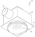
도 1은 본 발명에 따른 공기 흡배기 장치를 도시한 조립 사시도이며,
도 2는 본 발명에 따른 공기 흡배기 장치를 도시한 분해 사시도이며,
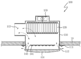
도 3은 본 발명에 따른 공기 흡배기 장치의 설치 단면도이며,
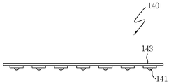
도 4는 본 발명의 제 1실시예에 따른 광원부의 구성도이며,
도 5는 본 발명의 제 2실시예에 따른 광원부의 구성도이다.1 is an assembled perspective view showing an air intake and exhaust device according to the present invention;
2 is an exploded perspective view illustrating an air intake and exhaust device according to the present invention;
3 is a cross-sectional view of the installation of the air intake and exhaust device according to the present invention;
4 is a configuration diagram of a light source unit according to a first embodiment of the present invention;
5 is a configuration diagram of a light source unit according to a second embodiment of the present invention.
이하, 첨부된 도면을 참조하면서 본 발명에 대해 상세하게 설명한다.Hereinafter, the present invention will be described in detail with reference to the accompanying drawings.
도 1은 본 발명의 실시예에 따른 공기 흡배기 장치를 도시한 조립 사시도이며, 도 2는 본 발명의 실시예에 따른 공기 흡배기 장치를 도시한 분해 사시도이며, 도 3은 본 발명의 실시예에 따른 공기 흡배기 장치의 설치 단면도이다.1 is an assembled perspective view showing an air intake and exhaust device according to an embodiment of the present invention, Figure 2 is an exploded perspective view showing an air intake and exhaust device according to an embodiment of the present invention, Figure 3 is according to an embodiment of the present invention It is installation sectional drawing of an air intake and exhaust device.
본 발명에 따른 공기 흡배기 장치(100)는 실내 천장패널(10)에 설치되어 오염된 실내공기를 흡입 배출하거나, 맑은 외부공기 또는 여과된 공기를 실내에 공급하는 것으로, 조명기능 및 살균기능이 더 형성된다.The air intake and
이와 같은 공기 흡배기 장치(100)는, 하우징(110)과, 팬(120)과, 모터(130)를 포함하여 이루어진 통상의 환풍기 또는 송풍기의 구성에서 광원부(140) 및 확산부(150)가 더 형성된 것이다.
The air intake and
상기에서 하우징(110)은 천장패널(10)에 결합 설치되는 것으로, 내부는 중공된 공간부를 형성하며, 하부 가장자리에는 플랜지(111)가 수평으로 형성되어 천장패널(10)에 맞대어 나사로 고정될 수 있도록 하였다.The
또한, 하우징(110) 하부는 팬(120)의 회전에 따라 공기를 흡입하거나 배출할 수 있도록 개구된 형태의 흡배기공(112)을 형성하고, 측방향에는 흡입 또는 배기되는 공기가 이동할 수 있는 공기이동통공(113)을 최소 하나 이상 형성한다.
In addition, the lower portion of the
상기에서 팬(120)과 모터(130)는 하우징(110) 내부에 설치되는 것으로, 모터(130)의 구동으로부터 팬(120)이 회전하되, 팬(120)의 회전 방향에 따라 하우징(110) 하부의 흡배기공(112)을 통해 실내 공기를 흡입하거나, 외부공기 또는 여과된 공기를 실내로 송풍하는 기능을 한다.
The
상기에서 광원부(140)는 팬(120)과 확산부(150) 사이에 위치하여 하우징(110) 또는 확산부(150)에 고정 설치되는 것으로, 하측 방향으로 조명용 광을 조사하거나 하우징(110) 내부의 공기를 살균하는 것이다.The
보다 상세하게는, 광원부(140)의 구성은 하측 방향으로 조명용 가시광선을 조사하도록 설치된 다수의 조명용엘이디(141)와, 하우징(110) 내부의 어느 일 방향으로 100nm ? 400nm의 파장값을 갖는 자외선을 조사하여 내부 공기를 살균하는 자외선엘이디(142)와, 구동회로가 형성된 인쇄회로기판(143)을 포함하여 구성된다.In more detail, the configuration of the
이와 같은 광원부(140)에서, 조명용엘이디(141) 및 자외선엘이디(142)의 배치는 다양한 실시 방법에 의해 구현될 수 있을 것이나, 도 4에 도시한 바와 같이 하나의 인쇄회로기판(143)에서 조명용엘이디(141) 및 자외선엘이디(142)를 혼합 배치하는 방법과, 도 5에 도시한 바와 같이 하나의 인쇄회로기판(143)을 기준으로 하측 방향에는 조명용엘이디(141)가 실장되고 상측 방향에는 자외선엘이디(142)가 실장되도록 구성하여 조명용 광은 하측을 조사하도록 하고 살균용 자외선은 하우징(110) 내부를 조사하도록 구성할 수도 있다.
In such a
상기에서 확산부(150)는 하우징(110) 하부에서 조명용엘이디(141)로부터 조사된 빛을 확산시킬 수 있도록 구성된 것으로, 빛 확산판(151) 및 다수의 지지대(152)를 포함하여 구성된다.The
상기에서 빛 확산판(151)은 조사되는 빛의 굴절로부터 빛을 확산시키는 것으로 요철부를 형성한 프레넬렌즈 타입의 투광성 패널이거나, 볼록 또는 오목하게 굴곡된 타입의 투광성 패널이 적용될 수 있다.The
지지대(152)는 상기 빛 확산판(151)의 내측면에서 하우징(110)을 향해 연장 형성된 것으로, 선단에는 하우징(110)과 고정될 수 있는 결합수단을 형성한다. 또한, 지지대(152)는 빛 확산판(151)을 하우징(110)으로부터 일정 거리 이격된 상태에서 고정할 수 있도록 구성된 것으로, 하우징(110)과 빛 확산판(151)의 이격된 공간으로 하우징(110) 내부 공기가 배출되거나, 실내 공기가 하우징(110) 측으로 흡입될 수 있는 것이다.
상기한 바와 같이, 본 발명의 기술적 사상을 바람직한 실시 예를 참조하여 설명하였지만 해당 기술분야의 숙련된 당업자라면 하기의 특허청구범위에 기재된 본 발명의 사상 및 영역으로부터 벗어나지 않는 범위 내에서 본 발명을 다양하게 수정 및 변경시킬 수 있는 것이다.
While the present invention has been particularly shown and described with reference to exemplary embodiments thereof, it will be understood by those of ordinary skill in the art that various changes in form and details may be made therein without departing from the spirit and scope of the invention as defined by the appended claims. And can be modified and changed.
10 : 천장패널 100 : 공기 흡배기 장치
110 : 하우징 111 : 플랜지
112 : 흡배기공 113 : 공기이동통공
120 : 팬 130 : 모터
140 : 광원부 141 : 조명용엘이디
142 : 자외선엘이디 143 : 인쇄회로기판
150 : 확산부 151 : 빛 확산판
152 : 지지대10: ceiling panel 100: air intake and exhaust device
110
112: intake and exhaust pores 113: air moving through
120: fan 130: motor
140: light source 141: LED for lighting
142: UV LED 143: printed circuit board
150 diffuser 151 light diffuser plate
152 support
Claims (2)
상기 하우징(110) 내부에 수용되어 회전함으로써 공기를 일 방향으로 흡입 또는 배출시키는 팬(120)과;
상기 하우징(110) 내부에 수용되어 상기 팬(120)을 구동시키는 모터(130)와;
상기 팬(120) 하부에 위치하는 것으로, 하측 방향으로 조명용 가시광선을 조사하도록 설치된 다수의 조명용엘이디(141)와, 하우징(110) 내부의 어느 일 방향으로 100nm ? 400nm의 파장값을 갖는 자외선을 조사하여 내부 공기를 살균하는 자외선엘이디(142)와, 구동회로가 형성된 인쇄회로기판(143)을 포함하는 광원부(140)와;
상기 하우징(110) 하부에서 조명용엘이디(141)로부터 조사된 빛을 확산시킬 수 있도록 구성된 것으로, 조사되는 빛을 굴절시켜 빛을 확산하는 빛 확산판(151)과, 상기 빛 확산판(151)의 내측면에서 하우징(110)을 향해 연장 형성되는 것으로 빛 확산판(151)이 하우징(110)과 일정 거리 이격된 상태에서 고정 지지될 수 있도록 형성된 지지대(152)를 포함하는 확산부(150);를 포함하여 구성된 것을 특징으로 하는 조명 및 살균 기능을 갖는 공기 흡배기 장치.
It is coupled to the indoor ceiling panel 10, the interior forms a hollow space portion, the lower portion forms an intake and exhaust hole 112 of the open shape, the air movement through the air can move to the 113 (113) At least one housing 110;
A fan (120) accommodated in the housing (110) and rotated to suck or discharge air in one direction;
A motor (130) accommodated in the housing (110) to drive the fan (120);
Located at the bottom of the fan 120, a plurality of LEDs for illumination 141 installed to irradiate visible light for downward in the downward direction, and 100nm in any one direction inside the housing 110. A light source unit 140 including an ultraviolet LED 142 for sterilizing internal air by irradiating ultraviolet rays having a wavelength value of 400 nm and a printed circuit board 143 on which a driving circuit is formed;
The light diffusion plate 151 is configured to diffuse light emitted from the lighting LED 141 under the housing 110, and diffuses light by refracting the irradiated light, and the light diffusion plate 151 of the light diffusion plate 151. A diffusion part 150 extending from the inner side toward the housing 110 and including a support 152 formed to be fixedly supported in a state where the light diffusion plate 151 is spaced apart from the housing 110 by a predetermined distance; Air intake and exhaust device having a lighting and sterilizing function, characterized in that configured to include.
상기 광원부(140)는, 하나의 인쇄회로기판(143)을 기준으로 하측 방향에는 조명용엘이디(141)가 실장되어 조명용 광을 하측 방향으로 조사하고, 상측 방향에는 자외선엘이디(142)가 실장되어 살균용 자외선이 하우징(110) 내부를 조사하도록 구성된 것을 특징으로 하는 조명 및 살균 기능을 갖는 공기 흡배기 장치.
The method of claim 1,
The light source unit 140 is mounted with a lighting LED 141 in the lower direction based on one printed circuit board 143 to irradiate the lighting light in the lower direction, and the ultraviolet LED 142 is mounted and sterilized in the upper direction. Ultraviolet intake and exhaust device having a lighting and sterilizing function, characterized in that the ultraviolet rays for the configuration configured to irradiate the housing (110).
Priority Applications (1)
| Application Number | Priority Date | Filing Date | Title |
|---|---|---|---|
| KR1020100136682A KR20120074746A (en) | 2010-12-28 | 2010-12-28 | Air circulation having illumination and sterilization ability |
Applications Claiming Priority (1)
| Application Number | Priority Date | Filing Date | Title |
|---|---|---|---|
| KR1020100136682A KR20120074746A (en) | 2010-12-28 | 2010-12-28 | Air circulation having illumination and sterilization ability |
Publications (1)
| Publication Number | Publication Date |
|---|---|
| KR20120074746A true KR20120074746A (en) | 2012-07-06 |
Family
ID=46708827
Family Applications (1)
| Application Number | Title | Priority Date | Filing Date |
|---|---|---|---|
| KR1020100136682A KR20120074746A (en) | 2010-12-28 | 2010-12-28 | Air circulation having illumination and sterilization ability |
Country Status (1)
| Country | Link |
|---|---|
| KR (1) | KR20120074746A (en) |
Cited By (4)
| Publication number | Priority date | Publication date | Assignee | Title |
|---|---|---|---|---|
| CN105987446A (en) * | 2014-11-06 | 2016-10-05 | 首尔伟傲世有限公司 | A compact air cleaner using a UV light emitting diode and a photocatalytic filter |
| KR20210082863A (en) * | 2019-12-26 | 2021-07-06 | 주식회사 알토 | Integrated lighting unit of air conditioning and lighting |
| KR20210155675A (en) * | 2020-06-16 | 2021-12-23 | 주식회사 힘펠 | Ventilator and Installation Method of Ventilator |
| KR20220040660A (en) | 2020-09-24 | 2022-03-31 | 정찬섭 | A tetrapod with concealed ring binder |
-
2010
- 2010-12-28 KR KR1020100136682A patent/KR20120074746A/en active IP Right Grant
Cited By (5)
| Publication number | Priority date | Publication date | Assignee | Title |
|---|---|---|---|---|
| CN105987446A (en) * | 2014-11-06 | 2016-10-05 | 首尔伟傲世有限公司 | A compact air cleaner using a UV light emitting diode and a photocatalytic filter |
| CN105987446B (en) * | 2014-11-06 | 2019-11-12 | 首尔伟傲世有限公司 | Compact air purifier including UV light emitting diode and photocatalytic filter |
| KR20210082863A (en) * | 2019-12-26 | 2021-07-06 | 주식회사 알토 | Integrated lighting unit of air conditioning and lighting |
| KR20210155675A (en) * | 2020-06-16 | 2021-12-23 | 주식회사 힘펠 | Ventilator and Installation Method of Ventilator |
| KR20220040660A (en) | 2020-09-24 | 2022-03-31 | 정찬섭 | A tetrapod with concealed ring binder |
Similar Documents
| Publication | Publication Date | Title |
|---|---|---|
| KR101842003B1 (en) | Ceiling type air cleaner | |
| US20210364178A1 (en) | Air and surface disinfecting system | |
| KR101320703B1 (en) | Multi-functional ventilating unit | |
| KR101125750B1 (en) | Lighting apparatus for bathroom and method for controlling the same | |
| JP2018162898A (en) | Air conditioning device | |
| KR20120074746A (en) | Air circulation having illumination and sterilization ability | |
| CN112402681A (en) | Ultraviolet sterilization panel light | |
| KR101767510B1 (en) | Lighting device | |
| US20220249729A1 (en) | Led light troffer with uv sanitized air return | |
| KR100668938B1 (en) | UV Sterilizing System of Elevator | |
| JP3160820U (en) | Ozone generator combined with lighting | |
| KR101715569B1 (en) | Ventilator with light for bathroom | |
| JP2013072626A (en) | Air conditioning apparatus with lighting equipment | |
| US20230220156A1 (en) | Combination mobile built-in air flow mechanism and led kill chamber | |
| JP6857843B2 (en) | Electrical equipment | |
| JP2005290754A (en) | Ventilator for door | |
| KR20220018694A (en) | Lighting apparatus having indoor sterilization function | |
| BR102021009899A2 (en) | AIR AND SURFACE DISINFECTION SYSTEM | |
| US20230213223A1 (en) | System and method for ventilation | |
| KR200362941Y1 (en) | Illuminator for elevator | |
| KR102594271B1 (en) | Air pollutant decomposition and sterilization device | |
| WO2023095327A1 (en) | Downlight | |
| JP6867719B1 (en) | Indoor lighting Air purification device and air purification method | |
| JP2010029553A (en) | Ion generating unit and illuminating apparatus | |
| KR100668941B1 (en) | Illuminator for elevator |
Legal Events
| Date | Code | Title | Description |
|---|---|---|---|
| A201 | Request for examination | ||
| E701 | Decision to grant or registration of patent right | ||
| NORF | Unpaid initial registration fee |