KR101715569B1 - Ventilator with light for bathroom - Google Patents
Ventilator with light for bathroom Download PDFInfo
- Publication number
- KR101715569B1 KR101715569B1 KR1020160109204A KR20160109204A KR101715569B1 KR 101715569 B1 KR101715569 B1 KR 101715569B1 KR 1020160109204 A KR1020160109204 A KR 1020160109204A KR 20160109204 A KR20160109204 A KR 20160109204A KR 101715569 B1 KR101715569 B1 KR 101715569B1
- Authority
- KR
- South Korea
- Prior art keywords
- cover
- led
- light
- fixing
- main body
- Prior art date
Links
Images


Classifications
-
- F—MECHANICAL ENGINEERING; LIGHTING; HEATING; WEAPONS; BLASTING
- F24—HEATING; RANGES; VENTILATING
- F24F—AIR-CONDITIONING; AIR-HUMIDIFICATION; VENTILATION; USE OF AIR CURRENTS FOR SCREENING
- F24F7/00—Ventilation
- F24F7/04—Ventilation with ducting systems, e.g. by double walls; with natural circulation
- F24F7/06—Ventilation with ducting systems, e.g. by double walls; with natural circulation with forced air circulation, e.g. by fan positioning of a ventilator in or against a conduit
- F24F7/10—Ventilation with ducting systems, e.g. by double walls; with natural circulation with forced air circulation, e.g. by fan positioning of a ventilator in or against a conduit with air supply, or exhaust, through perforated wall, floor or ceiling
-
- F—MECHANICAL ENGINEERING; LIGHTING; HEATING; WEAPONS; BLASTING
- F21—LIGHTING
- F21K—NON-ELECTRIC LIGHT SOURCES USING LUMINESCENCE; LIGHT SOURCES USING ELECTROCHEMILUMINESCENCE; LIGHT SOURCES USING CHARGES OF COMBUSTIBLE MATERIAL; LIGHT SOURCES USING SEMICONDUCTOR DEVICES AS LIGHT-GENERATING ELEMENTS; LIGHT SOURCES NOT OTHERWISE PROVIDED FOR
- F21K9/00—Light sources using semiconductor devices as light-generating elements, e.g. using light-emitting diodes [LED] or lasers
- F21K9/60—Optical arrangements integrated in the light source, e.g. for improving the colour rendering index or the light extraction
-
- F—MECHANICAL ENGINEERING; LIGHTING; HEATING; WEAPONS; BLASTING
- F21—LIGHTING
- F21V—FUNCTIONAL FEATURES OR DETAILS OF LIGHTING DEVICES OR SYSTEMS THEREOF; STRUCTURAL COMBINATIONS OF LIGHTING DEVICES WITH OTHER ARTICLES, NOT OTHERWISE PROVIDED FOR
- F21V23/00—Arrangement of electric circuit elements in or on lighting devices
- F21V23/001—Arrangement of electric circuit elements in or on lighting devices the elements being electrical wires or cables
- F21V23/002—Arrangements of cables or conductors inside a lighting device, e.g. means for guiding along parts of the housing or in a pivoting arm
-
- F—MECHANICAL ENGINEERING; LIGHTING; HEATING; WEAPONS; BLASTING
- F21—LIGHTING
- F21V—FUNCTIONAL FEATURES OR DETAILS OF LIGHTING DEVICES OR SYSTEMS THEREOF; STRUCTURAL COMBINATIONS OF LIGHTING DEVICES WITH OTHER ARTICLES, NOT OTHERWISE PROVIDED FOR
- F21V33/00—Structural combinations of lighting devices with other articles, not otherwise provided for
- F21V33/0088—Ventilating systems
-
- F—MECHANICAL ENGINEERING; LIGHTING; HEATING; WEAPONS; BLASTING
- F24—HEATING; RANGES; VENTILATING
- F24F—AIR-CONDITIONING; AIR-HUMIDIFICATION; VENTILATION; USE OF AIR CURRENTS FOR SCREENING
- F24F13/00—Details common to, or for air-conditioning, air-humidification, ventilation or use of air currents for screening
- F24F13/20—Casings or covers
-
- F—MECHANICAL ENGINEERING; LIGHTING; HEATING; WEAPONS; BLASTING
- F21—LIGHTING
- F21Y—INDEXING SCHEME ASSOCIATED WITH SUBCLASSES F21K, F21L, F21S and F21V, RELATING TO THE FORM OR THE KIND OF THE LIGHT SOURCES OR OF THE COLOUR OF THE LIGHT EMITTED
- F21Y2101/00—Point-like light sources
-
- F—MECHANICAL ENGINEERING; LIGHTING; HEATING; WEAPONS; BLASTING
- F24—HEATING; RANGES; VENTILATING
- F24F—AIR-CONDITIONING; AIR-HUMIDIFICATION; VENTILATION; USE OF AIR CURRENTS FOR SCREENING
- F24F2221/00—Details or features not otherwise provided for
- F24F2221/14—Details or features not otherwise provided for mounted on the ceiling
-
- F—MECHANICAL ENGINEERING; LIGHTING; HEATING; WEAPONS; BLASTING
- F24—HEATING; RANGES; VENTILATING
- F24F—AIR-CONDITIONING; AIR-HUMIDIFICATION; VENTILATION; USE OF AIR CURRENTS FOR SCREENING
- F24F2221/00—Details or features not otherwise provided for
- F24F2221/18—Details or features not otherwise provided for combined with domestic apparatus
Abstract
Description
본 발명은 화장실 또는 욕실의 천장에 설치되는 환풍기에 관한 것으로, 보다 상세하게는 욕실의 바닥과 욕조에 설치된 배수구 및 변기 등에서 발생하는 악취와 목욕 또는 샤워 도중에 발생하는 과도한 습기를 외부로 신속히 배출하고, 환기 장치가 설치된 본체의 하부로 결합되는 중간 커버에 구비된 흡입 그릴이 외부로 직접 노출되는 것을 방지하여 주변과 조화를 이룰 수 있는 가운데 환기가 원활하게 이루어지도록 하고, 아울러 흡입 그릴의 하부에 위치하는 하부 커버에 LED를 이용한 조명을 결합시켜 환기와 동시에 실내 공간을 밝힐 수 있도록 하여 천장에 조명등과 환기구를 별도로 각각 설치할 필요가 없으므로 시공 시간, 시공 비용을 절감할 수 있을 뿐만 아니라, 환풍기의 설치만으로 환기 기능과 조명 기능을 동시에 해결할 수 있도록 한 조명등을 겸한 욕실용 환풍기에 관한 것이다. BACKGROUND OF THE INVENTION 1. Field of the Invention The present invention relates to a ventilator installed in a ceiling of a bathroom or a bathroom, and more particularly to a ventilator installed in a ceiling of a bathroom or a bathroom, The suction grill provided on the intermediate cover coupled to the lower portion of the main body provided with the ventilation device is prevented from being directly exposed to the outside, so that the ventilation can be smoothly performed while the ventilation device is in harmony with the surroundings, It is possible to reduce the construction time and the installation cost by installing the lighting lamp and the ventilating hole separately on the ceiling since the indoor space can be illuminated simultaneously with the ventilation by combining the lighting using the LED on the lower cover, Lighting that can simultaneously solve functions and lighting functions A doubling relates to a fan for the bathroom.
일반적으로 욕실 내의 공기를 맑게 하기 위한 환기 방안으로 환풍기가 사용되고 있다.Generally, a ventilator is used as a ventilation system for clearing air in a bathroom.
환풍기는 실내의 천장이나 벽면에 고정되어 흡입구와 배출구를 구비하는 본체와, 상기 본체에 내장되어 실내의 공기를 외부로 배출시키는 팬과, 중간 커버에 구비되는 흡입 그릴과, 상기 본체의 배출구에 설치되어 팬의 구동시 자동으로 개폐되는 댐퍼 등으로 구성되어 있다.The ventilator is fixed to a ceiling or a wall surface of the room, and includes a main body having an inlet and an outlet, a fan built in the main body to discharge air to the outside, a suction grille provided in the middle cover, And a damper that is automatically opened and closed when the fan is driven.
환풍기는 본체에 내장된 팬이 회전됨과 동시에 발생하는 팬의 흡입력에 의하여 흡입 그릴을 통해 주변의 오염된 공기를 흡입하고, 흡입된 오염 공기가 배출구 및 댐퍼를 통해 배출되는 과정에서 환기가 이루어지게 된다.The ventilator sucks the polluted air around the suction grille by the suction force of the fan generated at the same time as the fan built in the main body rotates and ventilation is performed in the course of the suction of the polluted air through the discharge port and the damper .
이러한 환풍기는 단지 실내 환기를 위해서 사용되는 단순한 기능밖에 없기 때문에 효율성이 낮아지는 문제점이 있었다. Such a ventilator has only a simple function used for ventilation of the room, and thus has a problem in that efficiency is lowered.
또한, 중간 커버의 흡입구 측에 설치된 흡입 그릴이 외부에 그대로 노출됨에 따라 주변과 조화를 이루지 못하여 이질감을 불러 일으키는 또 다른 문제점이 있었다.Further, since the suction grille provided on the suction port side of the intermediate cover is directly exposed to the outside, there is another problem in that it can not harmonize with the surroundings and causes a sense of heterogeneity.
대한민국 등록실용신안공보 제 20-0433253호에서는 조명등이 결합된 환풍기의 커버를 제안한 바 있다. Korean Utility Model Registration No. 20-0433253 has proposed a cover for a ventilator which is combined with a lighting lamp.
상기 고안에서 제시한 LED 면상발광체는 두께가 매우 얇아서 미관상 보기 좋지만 무게가 무거우므로 상기 LED 면상발광체가 바닥으로 낙하할 위험이 있었다.The LED surface light emitter proposed in the above design has a very thin thickness, which is aesthetically pleasing, but is heavy in weight, so that the LED surface light emitter may fall to the floor.
또한, 상기 고안에서 LED 면상발광체를 작동시키는 구체적인 구성이 제시되어있지 않으므로 실제로 구현하기에는 어려움이 있었다.In addition, since the specific configuration for operating the LED surface light emitter is not disclosed in the above design, it has been difficult to actually implement the LED light emitter.
그리고 대한민국 등록실용신안공보 제 20-0466988호에서는 엘이디 그릴 조립체를 구비하는 환풍기를 제안한 바 있다.In Korean Utility Model Registration No. 20-0466988, a ventilator having an LED grill assembly has been proposed.
하지만, 상기 고안에서의 LED 조명은 천장에서 바로 수직 하방을 향하여 비추는 방식이므로 빛이 한 곳에 집중되어 자극적이기 때문에 사용자로 하여금 불편함을 초래할 수 있다. However, since the LED lighting in the above design is a method of directing downward from the ceiling toward the vertical direction, the light is concentrated in one place and is irritating, which may cause inconvenience to the user.
또한, 빛을 비추는 범위가 수직 하방의 일부 정도로 국한되므로 실내 공간을 전체적으로 밝히기 어렵다는 문제점이 있다.Further, since the range of illuminating the light is limited to a part of the vertical downward direction, there is a problem that it is difficult to illuminate the indoor space as a whole.
한편, 대한민국 공개실용신안공보 제 20-2011-0001397호에서는 조명등을 겸한 욕실용 환기팬을 제안한 바 있다.On the other hand, Korean Utility Model Publication No. 20-2011-0001397 proposes a ventilation fan for a bathroom which also functions as a lighting lamp.
하지만, 상기 고안의 LED 조명 장치는 그 규모가 크고 두께가 두꺼워서 환기팬의 중심에서 차지하는 공간이 크기 때문에 상기 환기팬의 소형화를 이루기 어려울 뿐만 아니라 설치 및 분해가 어렵다는 문제점이 있다.However, the designed LED lighting device has a large size and a large thickness so that the ventilation fan occupies a large space in the center of the ventilation fan, so that the ventilation fan is difficult to miniaturize and difficult to install and disassemble.
한편, 대한민국 공개실용신안공보 제 20-2011-0005268호에서는 LED 조명램프를 구비하는 환기장치를 제안한 바 있다.On the other hand, Korean Utility Model Laid-Open No. 20-2011-0005268 proposes a ventilation apparatus equipped with an LED illumination lamp.
하지만, 상기 고안에서 사용하는 환기용 팬은 시로코팬 또는 횡류팬으로 구성되어 그 구동 장치의 구성이 복잡하여 설치 및 시공 단가가 상승된다는 문제점이 있다. However, the ventilation fan used in the above-mentioned design is composed of a sirocco fan or a cross flow fan, and the structure of the driving device is complicated, raising the installation and construction cost.
상기한 바와 같은 종래의 문제점을 해결하기 위한 본 발명의 목적은 환풍기의 하부에 장착되는 하부 커버 외판의 중앙 하면에 간접조명식 엣지발광타입 LED 조명장치를 일체로 결합하여 실내를 조명할 수 있게 구성된 조명등을 겸한 욕실용 환풍기를 제공하고자 하는 것이다. According to an aspect of the present invention, there is provided an indoor lighting system comprising: a bottom cover plate mounted on a lower portion of a ventilator; To provide a ventilator for a bathroom.
또한, 엣지발광타입 LED 조명장치의 부피를 환풍기 커버의 두께 내에서 무시할 정도로 얇게 만들어서 종래의 것처럼 천장의 하방으로 조명 장치가 돌출되는 일이 없이 환풍기 본래의 커버 그대로 실내의 장식적 미감을 나타낼 수 있고, 조명등에서 열이 방출되지 않으므로 천장의 구성소재가 열로 인하여 변형되지 않을 뿐만 아니라 화재의 우려가 전혀 없고 보다 안전하고 편리하게 사용할 수 있는 환풍기를 제공하고자 하는 것이다.In addition, since the bulb of the edge-emitting type LED lighting apparatus is negligibly thinner than the thickness of the ventilator cover, the illuminating device does not protrude downward from the ceiling as in the prior art, The ceiling is not deformed due to heat, and there is no fear of fire, and it is intended to provide a ventilator that can be used more safely and conveniently.
또한, 환풍기를 천장에 설치하여 사용하는 중에 조명 기능을 위한 구성 부분의 수리 및 보수가 필요할 시, 환풍팬 부분과 엣지발광타입 LED 조명장치가 서로 완전히 분리 가능하여 해당 작업을 매우 편리하게 실시할 수 있는 환풍기를 제공하고자 하는 것이다.In addition, when the ventilation fan is installed on the ceiling and the repair and maintenance of the components for lighting function is required, the ventilation fan part and the edge emitting type LED lighting device can be completely separated from each other, To provide a ventilator.
또한, 간단한 구성요소를 이용하여 본체, 중간 커버, 하부 커버를 고정하여 엣지발광타입 LED 조명장치가 무거워도 낙하의 위험이 없게 하고자 하는 것이다. In addition, the main body, the intermediate cover, and the lower cover are fixed by using a simple component, so that there is no danger of falling even when the edge light-emitting type LED illumination device is heavy.
그러나 본 발명의 목적은 상기에 언급된 목적으로 제한되지 않으며, 언급되지 않았으나 아래 수단들 또는 실시예 상의 구체적인 구성에 따른 다른 목적들은 그 기재로부터 이 기술분야의 통상의 기술자에게 명확하게 이해될 수 있을 것이다.It is to be understood, however, that the intent of the invention is not to be limited to the above-mentioned objects, and that the following means or other objects according to the specific constructions of the embodiments may be clearly understood by those skilled in the art will be.
본 발명의 일실시예에 따르면, 조명등을 겸한 욕실용 환풍기(10)는 천장에 설치되어 공기를 흡입하는 본체(20)와; 상기 본체(20)에 결합되어 실내 공기가 유입되는 흡입 그릴(49)이 구비된 중간 커버(40); 및 상기 중간 커버(40)에 결합되어 실내 공기가 유입되는 경로가 되며, 전기 에너지를 제공받아 빛을 발생시키는 LED(83); 및 한 면이 금속 등으로 형성되어 빛이 투과할 수 없게 되어있으며 상기 LED(83)로부터 발산된 빛이 한 방향으로 진행될 수 있도록 하는 반사판(80), 모서리에 상기 LED(83)가 수평 방향으로 배치된 도광판(85), 도광판(85)의 내부에서 발산되는 LED(83)의 빛을 균일하게 확산시켜주는 역할을 하는 확산판(87), 상기 확산판(87)의 외부를 마감하는 조명 커버(89)로 구성되는 엣지발광타입 LED 조명장치가 설치된 하부 커버(60)를 포함하는 것을 특징으로 한다.According to an embodiment of the present invention, the
또한, 상기 본체(20)와 상기 중간 커버(40)를 연결하여 고정하며 한 쪽 끝에 숫나사부가 형성된 고정축(37)과; 상기 본체(20)의 하부 중심에 위치하며, 상기 고정축(37)을 상기 본체(20)에 고정하는 고정축 지지대(23)와; 상기 고정축(37)의 한 쪽 끝에 위치하며, 사각판 형상으로 형성되어 상기 고정축 지지대(23)의 모서리의 개방된 공간으로 진입하여 고정축(37)을 상기 본체(20)에 고정하는 고정축 결합부(33); 및 중심의 내부 면에 형성된 암나사부가 상기 고정축(37)의 한쪽 끝에 형성된 숫나사부에 끼워져서 회전되고, 상기 중간 커버(40)를 상기 본체(20)에 고정하는 중간 커버 고정손잡이(50)를 더 포함하는 것을 특징으로 한다.A
또한, 상기 고정축(37)의 길이 방향으로 옆면의 일부가 중심 범위까지 파여진 홈이 형성되어, 상기 홈으로 전선을 통과시켜서 엣지발광타입 LED 조명장치가 설치된 하부 커버(60)로 전원을 연결하는 것을 특징으로 한다.In addition, grooves are formed in the longitudinal direction of the
또한, 상기 중간 커버(40)의 하부 중심에 형성되어 상기 하부 커버(60)의 하부 커버 원통부(61)와 서로 회전 결합되는 중간 커버 원통부(41)와; 상기 중간 커버 원통부(41)의 하부 원주면의 내부 방향으로 서로 마주 보고 형성되어 상기 하부 커버 원통부(61)의 L형 홈(63)에 결합되는 고정 돌기(43)와; 상기 하부 커버(60)의 상부 중심에 형성되어 상기 중간 커버(40)의 중간 커버 원통부(41)와 서로 회전 결합되는 하부 커버 원통부(61); 및 상기 하부 커버 원통부(61)의 원주면에서 서로 마주 보고 L자 형태로 파여진 L형 홈(63)을 더 포함하는 것을 특징으로 한다.A middle cover
또한, 상기 중간 커버 원통부(41)와 상기 하부 커버 원통부(61)의 내부로 전선을 안내하여 외부로부터의 오염이나 습기에 대하여 상기 전선을 보호하는 것을 특징으로 한다.Further, the electric wire is guided into the intermediate cover
또한, 요구되는 광량에 따라서 상기 LED(83)를 도광판(85)의 한 모서리 내지 네 모서리의 옆면까지 선택하여 배치할 수 있는 것을 특징으로 한다.Also, the
또한, 상기 LED(83)가 설치된 면을 제외한 도광판(85)의 모서리 옆면은 빛을 차단할 수 있는 금속재 등이 추가되거나 접착되는 것을 특징으로 한다.In addition, a side surface of the edge of the
본 발명의 일실시예에 따르면 조명등을 겸한 욕실용 환풍기는 상기 환풍기의 중간 커버에 결합되는 하부 커버의 외판 중앙 하면에 간접조명식 엣지발광타입 LED 조명장치를 일체로 결합하여 실내를 조명할 수 있는 효과를 가진다.According to the embodiment of the present invention, the ventilator for a bathroom, which also serves as an illumination lamp, can be illuminated indoors by integrally connecting an indirect illumination type edge-emitting type LED illumination device to the lower surface of the center of the outer cover of the lower cover coupled to the middle cover of the ventilator .
또한, 엣지발광타입 LED 조명장치의 부피를 환풍기 커버의 두께 내에서 무시할 정도로 얇게 만들어서 천장의 하방으로 조명등이 돌출되는 일이 없이 환풍기 본래의 커버 그대로 실내의 장식적 미감을 나타낼 수 있고, 조명등에서 열이 방출되지 않으므로 천장의 구성소재가 열로 인하여 변형되지 않을 뿐만 아니라 화재의 우려가 전혀 없고 보다 안전하고 편리하게 사용할 수 있는 효과를 가진다.In addition, since the bulb of the edge light-emitting type LED illuminating device can be negligibly thin within the thickness of the ventilator cover, the decorative lightness of the interior can be displayed as it is the original cover of the ventilator without projecting the nightlight downward from the ceiling, So that the constituent material of the ceiling is not deformed due to heat, and there is no fear of fire, and it is safer and convenient to use.
또한, 환풍기 하부 커버 외판의 중앙 하면에 엣지발광타입 LED 조명장치를 일체로 부착되게 결합하여 그 구조가 매우 간단하고 고장이 없으며 엣지발광타입 LED 조명장치는 일반 전구와 달리 수명이 길기 때문에 빈번하게 전구를 교체하는 번거로운 불편이 없어서 보다 안전하고 편리하게 사용할 수 있는 효과를 가진다.In addition, the edge lighting type LED lighting device is integrally attached to the central bottom surface of the bottom plate of the ventilator bottom cover so that the structure thereof is very simple and does not breakdown. Since the edge lighting type LED lighting device has a long life, There is no inconvenience to replace the battery, so that the battery can be used more safely and conveniently.
또한, 환풍기를 천장에 설치하여 사용하는 중에 조명 기능을 위한 구성 부분의 수리 및 보수가 필요할 시, 환풍팬 부분과 엣지발광타입 LED 조명장치가 완전히 분리 가능하여 해당 작업을 매우 편리하게 실시할 수 있는 효과를 가진다.In addition, when the ventilation fan is installed on the ceiling and the repair and maintenance of the parts for lighting function is required, the ventilation fan part and the edge light emitting type LED lighting device can be completely separated, Effect.
또한, 간단한 구성요소를 이용하여 본체, 중간 커버, 하부 커버를 고정하여 엣지발광타입 LED 조명장치가 무거워도 낙하의 위험이 없도록 하는 효과를 가진다.In addition, the main body, the intermediate cover, and the lower cover are fixed using a simple component, so that there is no risk of falling even if the edge-emitting type LED lighting apparatus is heavy.
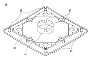
도 1은 본 발명의 일 실시예에 따른 조명등을 겸한 욕실용 환풍기(10)의 각 부분이 모두 결합된 전체적인 모습을 도시한 사시도이다.
도 2는 본 발명의 일 실시예에 따른 본체(20)를 분리하여 그 전체를 도시한 사시도이다.
도 3은 본 발명의 일 실시예에 따른 중간 커버(40)를 분리하여 그 전체를 아래에서 바라본 모습을 도시한 사시도이다.
도 4는 본 발명의 일 실시예에 따른 하부 커버(60)를 분리하여 그 전체를 위에서 바라본 모습을 도시한 사시도이다.
도 5는 본 발명의 일 실시예에 따른 하부 커버(60)의 하부 커버 고정부(65)를 확대한 모습을 도시한 확대도이다.
도 6은 본 발명의 일 실시예에 따른 하부 커버(60)의 엣지발광타입 LED 조명장치를 분리한 모습을 도시한 확대도이다.
도 7은 본 발명의 조명등을 겸한 욕실용 환풍기(10)를 욕실 공간 안에 설치한 모습을 도시한 참고도이다.FIG. 1 is a perspective view showing an overall structure in which all parts of a ventilator for a
FIG. 2 is a perspective view of the
FIG. 3 is a perspective view showing a state in which the
4 is a perspective view showing a state in which the
5 is an enlarged view showing an enlarged view of a lower
6 is an enlarged view showing a state in which the edge-emitting type LED lighting device of the
7 is a reference view showing a state in which a ventilator for a
본 발명의 특징 및 이점들은 첨부도면에 의거한 다음의 상세한 설명으로 더욱 명백해질 것이다. The features and advantages of the present invention will become more apparent from the following detailed description based on the accompanying drawings.
본 명세서 및 청구범위에 사용되는 용어나 단어는 통상적이고 사전적인 의미로 해석되어서는 아니 되며, 발명자가 그 자신의 발명을 가장 최선의 방법으로 설명하기 위하여 용어의 개념을 적절하게 정의한 것에 기초하고 있고 본 명세서의 기술적 용어는 단지 특정한 실시예를 설명하기 위하여 사용된 것으로, 본 발명을 한정하려는 의도가 아님을 유의하여 이러한 용어들에 대한 정의는 본 명세서 전반에 걸친 내용을 토대로 하여 내려져야 할 것이다. The terms and words used in the present specification and claims should not be construed in a conventional and dictionary sense and are based on the inventor having properly defined the concept of the term in order to describe its invention in the best way It is to be understood that the technical terminology used herein is for the purpose of describing particular embodiments only and is not intended to be limiting of the invention, and the definitions of such terms shall be based on their entirety throughout this specification.
또한, 본 명세서에서 사용되는 기술적 용어는 본 명세서에서 특별히 다른 의미로 정의되지 않는 한 본 발명이 속하는 기술 분야에서 통상의 지식을 가진 자에 의하여 일반적으로 이해되는 의미로 해석되어야 하며, 과도하게 포괄적인 의미로 해석되거나, 과도하게 축소된 의미로 해석되지 않아야 한다.Also, the technical terms used herein should be interpreted in a sense generally understood by a person skilled in the art to which the present invention belongs, unless otherwise defined in this specification, and it should be understood that an overly comprehensive It should not be construed as a meaning or an overly reduced meaning.
또한, 본 명세서에서 사용되는 단수의 표현은 문맥상 다르게 뜻하지 않는 한, 복수의 표현을 포함한다. Furthermore, the singular forms " a " as used herein include plural referents unless the context clearly indicates otherwise.
본 출원에서, "구성된다" 또는 "포함한다" 등의 용어는 명세서 상에 기재된 여러 구성 요소들 또는 여러 단계들을 반드시 모두 포함하는 것으로 해석되지 않아야 하며, 그 중 일부 구성 요소들 또는 일부 단계들은 포함되지 않을 수도 있고, 또는 추가적인 구성 요소 또는 단계들을 더 포함할 수 있는 것으로 해석되어야 하고 기술적 사상에 부합되는 의미와 개념으로 해석되어야 한다.In the present application, the term "comprising" or "comprising" or the like should not be construed as necessarily including the various elements or steps described in the specification, and some of the elements or portions thereof Or may include additional elements or steps, and should be construed as meaning and concept consistent with technical thought.
이하, 본 발명의 바람직한 실시예를 첨부된 도면을 참조하여 설명하기로 한다. 이 과정에서 도면에 도시된 선들의 두께나 구성요소의 크기 등은 설명의 명료함과 편의성을 위하여 과장되게 도시되어 있을 수 있다.Hereinafter, preferred embodiments of the present invention will be described with reference to the accompanying drawings. In this process, the thicknesses of the lines and the sizes of the components shown in the drawings may be exaggerated for clarity and convenience.
첨부된 도 1은 본 발명의 일 실시예에 따른 조명등을 겸한 욕실용 환풍기(10)의 각 부분이 모두 결합된 전체적인 모습을 도시한 사시도, 도 2는 본 발명의 일 실시예에 따른 본체(20)를 분리하여 그 전체를 도시한 사시도, 도 3은 본 발명의 일 실시예에 따른 중간 커버(40)를 분리하여 그 전체를 아래에서 바라본 모습을 도시한 사시도, 도 4는 본 발명의 일 실시예에 따른 하부 커버(60)를 분리하여 그 전체를 위에서 바라본 모습을 도시한 사시도, 도 5는 본 발명의 일 실시예에 따른 하부 커버(60)의 하부 커버 고정부(65)를 확대한 모습을 도시한 확대도, 도 6은 본 발명의 일 실시예에 따른 하부 커버(60)의 엣지발광타입 LED 조명장치를 분리한 모습을 도시한 확대도, 도 7은 본 발명의 조명등을 겸한 욕실용 환풍기(10)를 욕실 공간 안에 설치한 모습을 도시한 참고도이다.The accompanying Figure 1 is a perspective view showing the overall appearance of each part are both coupled in the bathroom exhaust fan (10) also serves as a night light according to an embodiment of the present invention, the main body according to an embodiment of the present invention Figure 2 is a (20 FIG. 3 is a perspective view showing a state in which the
본 발명에 따른 조명등을 겸한 욕실용 환풍기(10)는 욕실이나 화장실의 천장에 설치되는 것으로써 배출구가 덕트와 연결되어 공기 통로를 통해 실내 공기를 실외로 배출하는 본체(20)와, 상기 본체(20)의 하부에 장착되어 실내 공기를 흡입하는 흡입 그릴(49)이 구비된 중간 커버(40)와, 공기가 흡입되는 경로의 일부가 되는 동시에 LED(83)를 이용하여 실내를 조명하는 엣지발광타입 LED 조명장치가 포함된 하부 커버(60)로 구성된다. The ventilator ( 10 ) for a bathroom, which also serves as an illumination lamp, is installed on a ceiling of a bathroom or a toilet. The ventilator ( 10 ) is connected to a duct to discharge indoor air to the outside through an air passage. An
도 1에서는 위에서부터 아래의 순서로 본체(20), 중간 커버(40), 하부 커버(60)가 모두 결합되어 조립된 상태의 환풍기를 도시하고 있는데, 실제로 상기 환풍기가 천장에 설치될 때 본체(20)의 하부에 위치한 4개의 천장 지지대(27)는 천장의 상부에 위치하고, 중간 커버(40)의 테두리 부분은 천장의 하부에 위치하게 된다. FIG. 1 shows a ventilator in which the
실제로 조명등을 겸한 욕실용 환풍기(10)가 욕실 등의 천장에 설치되어 중간 커버(40)의 테두리 부분이 천장의 하부에 위치하고 있는 모습을 도 7에서 확인할 수 있다.In FIG. 7, a
도 2에서는 환풍기의 하부 커버(60)와 중간 커버(40)를 제거한 상태에서 본체(20)만을 따로 도시하였다.In FIG. 2, only the
하부가 개방되어있는 직육면체 형상의 본체(20)의 내부 중앙 상측에는 외부의 공기를 흡입하는 동력 장치가 설치되어있고, 상기 본체(20)의 옆면에 공기가 흐를 때는 개방되고, 공기가 흐르지 않을 때는 폐쇄되는 배출구 댐퍼가 설치되어있다.A power unit for sucking outside air is provided on the upper center of the inside of the rectangular parallelepiped-shaped
조명등을 겸한 욕실용 환풍기(10)를 설치하기 위하여 천장에 형성된 사각형 구멍의 모서리 상부에 천장 지지대(27)가 안착되어 상기 본체(20)가 천장의 상부에 고정될 수 있다.In order to install the
또한, 천장의 하부에서 상부로 끼워진 나사 등이 상기 천장 지지대(27)의 옆에 형성된 구멍으로 삽입되어 천장 지지대(27)가 천장에 견고하게 고정될 수 있다.Further, a screw or the like, which is fitted upward from the lower part of the ceiling, is inserted into the hole formed in the side of the
상기 천장 지지대(27)에 의하여 천장의 상부에 견고하게 고정된 본체(20)에 중간 커버(40)와 하부 커버(60)가 차례로 결합되어 조명등을 겸한 욕실용 환풍기(10)의 구성이 완성되는데, 먼저 중간 커버(40)를 본체(20)에 고정시키는 역할을 하는 고정축(37)을 설명하면 다음과 같다.The
고정축(37)의 확대된 형상은 도 2에서 확인할 수 있다.The enlarged shape of the fixed
도 2에서 고정축(37) 부분을 확대한 도면에서 보는 바와 같이, 고정축(37)의 한 쪽 끝의 일부 구간에는 숫나사부가 형성되어 있고, 다른 한 쪽 끝은 사각판 형상의 고정축 결합부(33)가 형성되어있다. As shown in the enlarged view of the fixed
원기둥 형상 고정축(37)의 길이 방향에 대하여 옆면의 일부는 고정축(37)의 중심 범위까지 파여진 형상이며, 사각판 형상의 고정축 결합부(33)의 한 쪽 모서리는 고정축 지지대(23)에 형성되어있는 결합홈(25)에 걸릴 수 있도록 걸이 형상으로 된 탄성 결합부(35)가 형성되어 있다.A part of the side surface of the cylindrical fixing
상기 고정축(37)의 길이 방향에 대하여 옆면의 일부가 중심 범위까지 파여진 형상으로 인하여, 본체(20) 쪽에 구비된 전선이 상기 고정축(37)의 중심을 통하여 중간 커버(40)의 하부로 나와서 엣지발광타입 LED 조명장치에 전력을 공급할 수 있다.A part of the side surface of the fixed
한편, 고정축 지지대(23)는 본체(20)의 동력 장치 하부 중심에 구비되어있고, 상기 고정축 결합부(33)가 진입할 수 있도록 한 옆면 부분이 개방되어있으며, 상기 고정축 지지대(23)의 중심에 고정축(37)이 위치할 수 있도록 상기 고정축 지지대(23)의 한 옆면으로부터 횡방향으로 파여있되, 상기 고정축 지지대(23)의 하부는 더 깊게 중심까지 파여진 형상이다.The fixed
고정축 결합부(33)는 횡방향으로 파여있는 고정축 지지대(23)의 개방된 한 옆면에 진입하여 삽입되되, 끝 부분이 걸이 형상으로 된 탄성 결합부(35)가 상기 고정축 지지대(23)에 형성된 결합홈(25)에 끼워져서 걸릴 때까지 삽입됨으로써, 본체(20)와 고정축(37)이 일체로 견고하게 결합될 수 있다.The fixed
중간 커버 고정손잡이(50)는 도 2에서 보는 바와 같이, 고정축 결합부(33)의 한 쪽 끝에 형성된 숫나사부에 돌려서 결합시킬 수 있도록 상기 중간 커버 고정손잡이(50)의 중심 내부 면에는 암나사부가 형성되어 있다.As shown in FIG. 2, the intermediate
중간 커버(40)의 중심에 형성된 구멍을 본체(20)에 결합된 고정축(37)에 대고 중간 커버(40)를 윗 방향으로 밀면 상기 고정축(37)이 중간 커버(40)의 중심에 형성된 구멍의 아래 방향으로 돌출되게 된다.The hole formed in the center of the
그리고 중간 커버 고정손잡이(50)의 중심 내면에 형성된 암나사부를 아래 방향으로 돌출된 상기 고정축(37)의 한 쪽 끝에 형성된 숫나사부에 돌려서 조여주면 상기 중간 커버 고정손잡이(50)의 직경이 중간 커버(40) 중심에 형성된 구멍의 직경보다 더 크므로 상기 중간 커버(40)가 아래 방향으로 떨어지지 않고 고정되게 된다.When the female screw portion formed on the center inner surface of the intermediate
또한, 상기 중간 커버 고정손잡이(50)를 회전시키며 조여줌에 따라 상기 중간 커버 고정손잡이(50)가 고정축(37)의 한 쪽 끝에 형성된 숫나사면을 따라 위로 더 상승하게 되어 상기 중간 커버 고정손잡이(50)의 상면이 상기 중간 커버(40)의 중심에 형성된 구멍 부근의 부재에 대하여 위로 압력을 가하게 되므로 본체(20)와 상기 중간 커버(40)가 견고하게 고정되는 효과를 가진다.The intermediate
상기의 과정을 거치면, 천장 위에 고정된 본체(20)에 삽입되어 견고하게 고정된 고정축(37)에 중간 커버(40)가 삽입되어 본체(20)와 중간 커버 고정손잡이(50) 사이에서 중간 커버(40)가 견고하게 고정될 수 있다.The
한편, 본체(20)에 결합된 중간 커버(40)와 하부 커버(60)가 서로 결합되는 과정은 다음과 같다.The process of coupling the
도 3에서 보는 바와 같이 중간 커버(40)는, 실내에서 천장을 바라보았을 때 환풍기의 테두리가 되며 천장에 노출되는 아래 부분과, 천장에 형성된 사각형 구멍 및 본체(20)에 형성된 4개의 천장 지지대(27)의 안쪽으로 삽입되는 윗 부분으로 나누어진다.As shown in FIG. 3, the
중간 커버(40)의 하부 중심에는 하방으로 개방된 중간 커버 원통부(41)가 있고, 상기 중간 커버 원통부(41)는 도 4에서 보는 바와 같이 상방으로 개방된 하부 커버 원통부(61)와 서로 맞물려 결합되되, 상기 중간 커버 원통부(41)의 직경이 더 커서 하부 커버 원통부(61)가 중간 커버 원통부(41)에 끼워지게 된다.The
또한, 상기 중간 커버(40)의 하부 네 귀퉁이에 형성된 하부 커버 체결홀(45)과 하부 커버(60)의 상부 네 귀퉁이에 형성된 하부 커버 고정부(65)가 서로 맞물려서 결합된다.The lower
중간 커버(40)와 하부 커버(60)가 서로 결합되는 과정을 더 자세하게 설명하면 다음과 같다.The process of coupling the
상기 중간 커버 원통부(41)는 일정한 길이를 가지는 파이프 형상으로 도 3에서 보는 바와 같이 중간 커버 원통부(41)의 하부 끝에 원주면에서 서로 마주보며 안쪽으로 향하고 있는 2개의 고정 돌기(43)가 형성되어있다.As shown in FIG. 3, the intermediate cover
상기 고정 돌기(43)는 하부 커버 원통부(61)에 형성된 L형 홈(63)에 끼워져 결합되되, 중간 커버 원통부를 하부 커버 원통부에 끼운 상태에서 결합한다.The fixing
중간 커버 원통부(41)의 고정 돌기(43)는 하부 커버 원통부(61)의 상부에서 진입했다가, 하부 커버(60)를 돌려줌으로써 L형 홈(63)의 횡방향으로 형성되어있는 수평 방향의 홈으로 진입할 수 있게 된다.The fixing
L형 홈(63)의 수평 방향의 홈에 상기 고정 돌기(43)가 진입하면 하부 커버(60)가 중간 커버(40)에 고정될 수 있고, 하부 커버 고정부(65)와 하부 커버 체결홀(45)이 서로 체결될 수 있도록 일직선 상에 위치하게 된다.The
중간 커버(40)의 하부에는 외부의 공기를 흡입하기 위한 흡입 그릴(49)이 형성되어 있다.A
상기 흡입 그릴(49)은 격자형의 구멍들이 중간 커버 원통부(41) 외부면에서부터 시작되어 일정한 직경을 가지는 원 범위 안에 형성되어있다. The
하부 커버 체결홀(45)에 삽입되어 고정되는 하부 커버 고정부(65)를 더 자세하게 확대 도시한 도면을 도 5에서 확인할 수 있다.FIG. 5 shows a further enlarged view of the lower
상기 하부 커버 고정부(65)는 도 5에서 확대 도시된 바와 같이 절개 탄성부(67)와 반발 지지대(69)로 구성되어 있다.The lower
절개 탄성부(67)는 원통형의 하부 커버 고정부(65)의 일부가 절개된 형상이며, 상기 절개 탄성부(67)의 안쪽에서 상기 절개 탄성부(67)를 외부 방향으로 지지하여 탄성을 확보하여주는 반발 지지대(69)에 의하여 탄성력을 확보한다.The incision
도 5에서 보는 바와 같이 상기 절개 탄성부(67)에서 걸이 형상으로 형성된 부분의 끝이 중간 커버(40)의 하부 커버 체결홀(45)의 상부에 걸리면 하부 커버 고정부(65)가 하부 커버 체결홀(45)에 견고하게 고정될 수 있다.5, when the end of the hook-shaped portion of the incision
중간 커버(40)와 하부 커버(60)를 결합시키는 하부 커버 체결홀(45)과 하부 커버 고정부(65)는 네 쌍인 것이 바람직하다.It is preferable that the lower
상기 과정을 거쳐 중간 커버(40)에 형성된 중간 커버 원통부(41), 고정 돌기(43), 하부 커버 체결홀(45)과 하부 커버(60)에 형성된 하부 커버 원통부(61), L형 홈(63), 하부 커버 고정부(65)에 의하여 중간 커버(40)와 하부 커버(60)가 견고하게 고정될 수 있다. The
한편, 본 발명의 조명등을 겸한 욕실용 환풍기(10)는 실내 공기를 환기시키는 환풍의 기능뿐만 아니라 엣지발광타입 LED 조명장치를 이용하여 실내로 빛을 비추는 조명 기능도 가지고 있다.Meanwhile, the
도 4에서 반사판(80)의 상부를 볼 수 있고, 도 6에서는 더 구체적으로 엣지발광타입 LED 조명장치의 세부적인 부분을 분리하여 나타낸 모습을 볼 수 있다.In FIG. 4, the upper part of the
도 6에서 보는 바와 같이, 엣지발광타입 LED 조명장치의 가장 상부에 반사판(80)이 위치한다. As shown in FIG. 6, the
반사판(80)의 윗 부분은 금속재 등으로 형성되어 빛이 위로 투과될 수 없게 되어있으며 LED(83)로부터 발산된 빛이 모두 아래로 향할 수 있도록 한다.The upper portion of the
반사판(80)의 아래 부분은 백색으로 도색되어 있되, 환풍기를 설치하는 위치와 용도에 따라 그 도색 색상을 달리할 수 있다.The lower part of the
반사판(80)의 아래에는 도광판(85)이 위치한다. 도광판(85)의 한 모서리에는 LED(83)가 배치되고, 상기 LED(83)는 일정한 두께를 가진 도광판(85)의 모서리 옆면에서 도광판(85)의 면에 대하여 수평 방향으로 가로지르며 빛을 발산하게 된다.A
도광판(85)의 한 면에는 LED(83)의 빛이 손실없이 균일하게 퍼질 수 있도록 일정한 패턴이 형성되어 있다.A predetermined pattern is formed on one side of the
LED(83)가 설치된 모서리를 제외한 도광판(85)의 세 모서리에는 빛을 차단할 수 있는 금속재 등이 추가되거나 접착된다. A metal material or the like capable of blocking light is added to or bonded to the three corners of the
상기 금속재가 접착되는 이유는 LED(83)에서부터 발산된 모든 빛이 다른 모서리의 옆 면으로 새어나가지 않고 도광판(85) 내부에서만 머물도록 하기 위함이다.The reason why the metallic material is bonded is that all the light emitted from the
LED(83)는 도광판(85)의 한 모서리에 설치될 수도 있지만, 2면 내지 4면에 모두 설치되는 것도 가능하다.The
도광판(85)의 하부에는 확산판(87)이 위치하고, 상기 확산판(87)은 도광판(85)의 내부에서 발산되고 있는 LED(83)의 빛을 균일하게 확산시켜주는 역할을 한다.A
확산판(87)의 하부에는 조명 커버(89)가 위치하며, 상기 조명 커버(89)는 엣지발광타입 LED 조명 장치의 가장 외부에 설치된다. An illuminating
상기 반사판(80), 도광판(85), 도광판(85) 옆면의 LED(83), 확산판(87), 조명 커버(89)에 의하여 엣지발광타입 LED 조명장치의 구성이 완성된다.The structure of the edge light emitting type LED illumination device is completed by the
이상 구체적으로 첨부된 도면을 참조하여 본 발명의 실시예를 설명하였지만, 본 발명이 속하는 기술분야의 당업자는 본 발명이 그 기술적 사상이나 필수적 특징을 변경하지 않고 다른 구체적인 형태로 실시될 수 있다는 것을 이해할 수 있을 것이다.While the present invention has been particularly shown and described with reference to exemplary embodiments thereof, it is to be understood that the invention is not limited to the exemplary embodiments and constructions. It will be possible.
그러므로 이상에서 기술한 실시예는 모든 면에서 예시적인 것이고, 한정적인 것이 아닌 것으로 이해되어야 하며, 상기 상세한 설명에서 기술된 본 발명의 범위는 후술하는 특허청구범위에 의하여 나타내어지며, 특허청구범위의 의미 및 범위 그리고 그 등가 개념으로부터 도출되는 모든 변경 또는 변형된 형태가 본 발명의 범위에 포함되는 것으로 해석되어야 한다.It is therefore to be understood that the above-described embodiments are illustrative and not restrictive in all aspects and that the scope of the invention described in the foregoing specification is defined by the appended claims, And all equivalents and modifications that come within the meaning and range of equivalency of the claims are to be embraced within their scope.
10 : 조명등을 겸한 욕실용 환풍기
20 : 본체
23 : 고정축 지지대
25 : 결합홈
27 : 천장 지지대
33 : 고정축 결합부
35 : 탄성 결합부
37 : 고정축
40 : 중간 커버
41 : 중간 커버 원통부
43 : 고정 돌기
45 : 하부 커버 체결홀
49 : 흡입 그릴
50 : 중간 커버 고정손잡이
60 : 하부 커버
61 : 하부 커버 원통부
63 : L형 홈
65 : 하부 커버 고정부
67 : 절개 탄성부
69 : 반발 지지대
80 : 반사판
83 : LED
85 : 도광판
87 : 확산판
89 : 조명 커버 10 : Ventilator for bathroom with lighting
20:
23: Fixed shaft support
25: Coupling groove
27: Ceiling support
33: fixed shaft coupling portion
35: elastic coupling portion
37: Fixed shaft
40: middle cover
41: intermediate cover cylindrical portion
43: Fixing projection
45: Lower cover fastening hole
49: suction grill
50: Middle cover fixing knob
60: Lower cover
61: Lower cover cylinder part
63: L-shaped groove
65: Lower cover fixing portion
67: incision elastic part
69: rebound support
80: reflector
83: LED
85: light guide plate
87: diffuser plate
89: Lighting cover
Claims (7)
상기 본체(20)에 결합되어 실내 공기가 유입되는 흡입 그릴(49)이 구비된 중간 커버(40);
상기 중간 커버(40)에 결합되어 실내 공기가 유입되는 경로가 되며, 전기 에너지를 제공 받아 빛을 발생시키는 LED(83);
한 면이 금속으로 형성되어 빛이 투과할 수 없게 되어 있으며 상기 LED(83)로부터 발산된 빛이 한 방향으로 진행될 수 있도록 하는 반사판(80), 모서리에 상기 LED(83)가 수평 방향으로 배치된 도광판(85), 도광판(85)의 내부에서 발산되는 LED(83)의 빛을 균일하게 확산시켜주는 역할을 하는 확산판(87) 및 상기 확산판(87)의 외부를 마감하는 조명 커버(89)로 구성되는 엣지발광타입 LED 조명장치가 설치된 하부 커버(60);
상기 본체(20)와 상기 중간 커버(40)를 연결하여 고정하며 한 쪽 끝에 숫나사부가 형성된 고정축(37);
상기 본체(20)의 하부 중심에 위치하며, 상기 고정축(37)을 상기 본체(20)에 고정하는 고정축 지지대(23);
상기 고정축(37)의 한 쪽 끝에 위치하며, 사각판 형상으로 형성되어 상기 고정축 지지대(23)의 모서리의 개방된 공간으로 진입하여 삽입되되 끝부분이 걸이 형상으로 된 탄성결합부(35)에 끼워져서 걸릴 때까지 삽입됨으로써 상기 고정축(37)을 상기 본체(20)에 고정하는 고정축 결합부(33); 및
중심의 내부 면에 형성된 암나사부가 상기 고정축(37)의 한쪽 끝에 형성된 숫나사부에 끼워져서 회전되고, 상기 중간 커버(40)를 상기 본체(20)에 고정하는 중간 커버 고정손잡이(50)를 포함하고,
상기 고정축(37)의 길이 방향으로 옆면의 일부가 중심 범위까지 파여진 홈이 형성되어, 상기 홈으로 전선을 통과시켜서 엣지발광타입 LED 조명장치가 설치된 하부 커버(60)로 전원을 연결하는 것을 특징으로 하는 조명등을 겸한 욕실용 환풍기(10).
A main body 20 installed on the ceiling and sucking air;
An intermediate cover 40 coupled to the main body 20 and having a suction grill 49 into which room air flows;
An LED (83) coupled to the intermediate cover (40) and serving as a path through which indoor air flows, generating light by receiving electric energy;
A reflector 80 formed on the one surface of the reflector 80 so that the light emitted from the LED 83 can propagate in one direction and the LED 83 is arranged in the horizontal direction A diffusion plate 87 serving to uniformly diffuse the light of the LED 83 emitted from the inside of the light guide plate 85 and an illumination cover 89 closing the outside of the diffusion plate 87 A bottom cover 60 provided with an edge light-emitting type LED lighting device composed of a bottom cover 60;
A fixed shaft 37 fixedly connected to the main body 20 and the intermediate cover 40 and having a male screw part at one end;
A fixing shaft support 23 located at the lower center of the main body 20 and fixing the fixing shaft 37 to the main body 20;
An elastic coupling part 35 formed at one end of the fixed shaft 37 and formed in a rectangular plate shape and inserted into the open space at the corner of the fixed shaft support 23 and inserted at the end thereof, A fixed shaft coupling portion 33 for fixing the fixed shaft 37 to the main body 20 by being inserted into the main shaft 20 until it is engaged; And
And a middle cover fixing handle 50 for fixing the intermediate cover 40 to the main body 20 while being rotatably fitted to a male screw portion formed at one end of the fixing shaft 37 and,
A groove is formed in the longitudinal direction of the fixing shaft 37 so that a part of the side surface extends to the central range so that electric power is connected to the lower cover 60 provided with the edge light emitting type LED illumination device by passing the electric wire through the groove A bathroom ventilator ( 10 ) which also functions as an illumination lamp.
상기 중간 커버(40)의 하부 중심에 형성되어 상기 하부 커버(60)의 하부 커버 원통부(61)와 서로 회전 결합되는 중간 커버 원통부(41);
상기 중간 커버 원통부(41)의 하부 원주면의 내부 방향으로 서로 마주 보고 형성되어 상기 하부 커버 원통부(61)의 L형 홈(63)에 결합되는 고정 돌기(43);
상기 하부 커버(60)의 상부 중심에 형성되어 상기 중간 커버(40)의 중간 커버 원통부(41)와 서로 회전 결합되는 하부 커버 원통부(61); 및
상기 하부 커버 원통부(61)의 원주면에서 서로 마주 보고 L자 형태로 파여진 L형 홈(63)을 더 포함하는 것을 특징으로 하는 조명등을 겸한 욕실용 환풍기(10).
The method according to claim 1,
A middle cover cylindrical portion 41 formed at the lower center of the intermediate cover 40 and rotatably coupled with the lower cover cylindrical portion 61 of the lower cover 60;
Fixing projections (43) formed facing each other in the inner direction of the lower circumferential surface of the intermediate cover cylindrical portion (41) and engaged with the L-shaped grooves (63) of the lower cover cylindrical portion (61);
A lower cover cylindrical portion 61 formed at the upper center of the lower cover 60 and rotatably coupled with the intermediate cover cylindrical portion 41 of the intermediate cover 40; And
The lower cover cylindrical portion (61) lights for bathroom fans (10) also serves as a characterized in that facing each other on the peripheral surface further comprises a L-shape wave excitation L-shaped groove 63 of the.
Priority Applications (1)
| Application Number | Priority Date | Filing Date | Title |
|---|---|---|---|
| KR1020160109204A KR101715569B1 (en) | 2016-08-26 | 2016-08-26 | Ventilator with light for bathroom |
Applications Claiming Priority (1)
| Application Number | Priority Date | Filing Date | Title |
|---|---|---|---|
| KR1020160109204A KR101715569B1 (en) | 2016-08-26 | 2016-08-26 | Ventilator with light for bathroom |
Publications (1)
| Publication Number | Publication Date |
|---|---|
| KR101715569B1 true KR101715569B1 (en) | 2017-03-10 |
Family
ID=58410821
Family Applications (1)
| Application Number | Title | Priority Date | Filing Date |
|---|---|---|---|
| KR1020160109204A KR101715569B1 (en) | 2016-08-26 | 2016-08-26 | Ventilator with light for bathroom |
Country Status (1)
| Country | Link |
|---|---|
| KR (1) | KR101715569B1 (en) |
Cited By (3)
| Publication number | Priority date | Publication date | Assignee | Title |
|---|---|---|---|---|
| KR200487506Y1 (en) | 2017-11-22 | 2018-09-28 | 도스코산업 주식회사 | Ceiling embedded type ventilator |
| KR20200121462A (en) | 2019-04-16 | 2020-10-26 | 주식회사 성삼 | Bathroom ventilator |
| KR102594968B1 (en) | 2022-09-15 | 2023-10-27 | (주)서원에어테크 | Bathroom space ventilation system for emergency evacuation with intake and ventilation |
Citations (8)
| Publication number | Priority date | Publication date | Assignee | Title |
|---|---|---|---|---|
| KR200433253Y1 (en) | 2006-09-15 | 2006-12-08 | 이부규 | A cover with an led illuminator for a ventilation fan |
| KR20110001397U (en) | 2009-08-03 | 2011-02-10 | 도스코산업 주식회사 | Ventilation fan with light for bathroom |
| KR20110005268U (en) | 2009-11-20 | 2011-05-26 | (주)두영에너텍 | A ventilating apparatus having illumination lamp |
| KR20110076248A (en) * | 2009-12-29 | 2011-07-06 | 금호전기주식회사 | Led illuminating device |
| KR200466988Y1 (en) | 2011-01-21 | 2013-05-21 | 주식회사 힘펠 | Ventilator with the led grill assembly |
| KR20130117417A (en) * | 2012-04-17 | 2013-10-28 | 강성실 | Diffuser with lighting |
| KR20150140066A (en) * | 2014-06-05 | 2015-12-15 | 강성실 | LED Lighting is for a Bathroom Ventilation Device |
| KR101604290B1 (en) * | 2015-04-21 | 2016-03-17 | 구소연 | Lighting for edge |
-
2016
- 2016-08-26 KR KR1020160109204A patent/KR101715569B1/en active IP Right Grant
Patent Citations (8)
| Publication number | Priority date | Publication date | Assignee | Title |
|---|---|---|---|---|
| KR200433253Y1 (en) | 2006-09-15 | 2006-12-08 | 이부규 | A cover with an led illuminator for a ventilation fan |
| KR20110001397U (en) | 2009-08-03 | 2011-02-10 | 도스코산업 주식회사 | Ventilation fan with light for bathroom |
| KR20110005268U (en) | 2009-11-20 | 2011-05-26 | (주)두영에너텍 | A ventilating apparatus having illumination lamp |
| KR20110076248A (en) * | 2009-12-29 | 2011-07-06 | 금호전기주식회사 | Led illuminating device |
| KR200466988Y1 (en) | 2011-01-21 | 2013-05-21 | 주식회사 힘펠 | Ventilator with the led grill assembly |
| KR20130117417A (en) * | 2012-04-17 | 2013-10-28 | 강성실 | Diffuser with lighting |
| KR20150140066A (en) * | 2014-06-05 | 2015-12-15 | 강성실 | LED Lighting is for a Bathroom Ventilation Device |
| KR101604290B1 (en) * | 2015-04-21 | 2016-03-17 | 구소연 | Lighting for edge |
Cited By (3)
| Publication number | Priority date | Publication date | Assignee | Title |
|---|---|---|---|---|
| KR200487506Y1 (en) | 2017-11-22 | 2018-09-28 | 도스코산업 주식회사 | Ceiling embedded type ventilator |
| KR20200121462A (en) | 2019-04-16 | 2020-10-26 | 주식회사 성삼 | Bathroom ventilator |
| KR102594968B1 (en) | 2022-09-15 | 2023-10-27 | (주)서원에어테크 | Bathroom space ventilation system for emergency evacuation with intake and ventilation |
Similar Documents
| Publication | Publication Date | Title |
|---|---|---|
| CA2487548C (en) | Lighting and ventilating apparatus and method | |
| JP3231621B2 (en) | Lighted ventilation fan | |
| US20180266722A1 (en) | Illumination grille and assembly method | |
| CA2754514C (en) | Lighting and ventilating system and method | |
| US9004723B2 (en) | Lighting and ventilating system and method | |
| CN204611553U (en) | lamp with ventilating fan | |
| KR101715569B1 (en) | Ventilator with light for bathroom | |
| KR100984252B1 (en) | Ventilation fan for bathroom | |
| KR20120005436U (en) | motorized diffuser of VAV type with an LED light | |
| CA3065882A1 (en) | Integrated ventilation and illumination system | |
| JP6295438B2 (en) | Air conditioner | |
| JP4502851B2 (en) | Embedded ceiling air conditioner | |
| JP4721736B2 (en) | Embedded ceiling air conditioner | |
| KR20110005268U (en) | A ventilating apparatus having illumination lamp | |
| WO2019233350A1 (en) | Ceiling lamp having air flow guide wheel | |
| JP6803546B2 (en) | lighting equipment | |
| KR20120000170U (en) | Ventilation fan for bathroom having light emitting module | |
| KR20120074746A (en) | Air circulation having illumination and sterilization ability | |
| KR20110023636A (en) | Apparatus for both lighting and ventilating | |
| KR101398115B1 (en) | Illumination device with fan | |
| KR20150140066A (en) | LED Lighting is for a Bathroom Ventilation Device | |
| CN111810880A (en) | Connecting piece with multiple functions | |
| KR101369291B1 (en) | Diffuser with lighting | |
| CN110159566A (en) | A kind of no leaf Ceiling fan lamp | |
| JP2002042544A (en) | Lighting ventilation device |
Legal Events
| Date | Code | Title | Description |
|---|---|---|---|
| E701 | Decision to grant or registration of patent right | ||
| GRNT | Written decision to grant | ||
| FPAY | Annual fee payment |
Payment date: 20200304 Year of fee payment: 4 |