KR20120052902A - Battery - Google Patents
Battery Download PDFInfo
- Publication number
- KR20120052902A KR20120052902A KR1020117030459A KR20117030459A KR20120052902A KR 20120052902 A KR20120052902 A KR 20120052902A KR 1020117030459 A KR1020117030459 A KR 1020117030459A KR 20117030459 A KR20117030459 A KR 20117030459A KR 20120052902 A KR20120052902 A KR 20120052902A
- Authority
- KR
- South Korea
- Prior art keywords
- battery
- wound
- winding
- current collector
- electrode plate
- Prior art date
- Legal status (The legal status is an assumption and is not a legal conclusion. Google has not performed a legal analysis and makes no representation as to the accuracy of the status listed.)
- Granted
Links
Images


Classifications
-
- H—ELECTRICITY
- H01—ELECTRIC ELEMENTS
- H01M—PROCESSES OR MEANS, e.g. BATTERIES, FOR THE DIRECT CONVERSION OF CHEMICAL ENERGY INTO ELECTRICAL ENERGY
- H01M50/00—Constructional details or processes of manufacture of the non-active parts of electrochemical cells other than fuel cells, e.g. hybrid cells
- H01M50/30—Arrangements for facilitating escape of gases
- H01M50/317—Re-sealable arrangements
- H01M50/325—Re-sealable arrangements comprising deformable valve members, e.g. elastic or flexible valve members
-
- H—ELECTRICITY
- H01—ELECTRIC ELEMENTS
- H01M—PROCESSES OR MEANS, e.g. BATTERIES, FOR THE DIRECT CONVERSION OF CHEMICAL ENERGY INTO ELECTRICAL ENERGY
- H01M10/00—Secondary cells; Manufacture thereof
- H01M10/04—Construction or manufacture in general
- H01M10/0431—Cells with wound or folded electrodes
-
- H—ELECTRICITY
- H01—ELECTRIC ELEMENTS
- H01M—PROCESSES OR MEANS, e.g. BATTERIES, FOR THE DIRECT CONVERSION OF CHEMICAL ENERGY INTO ELECTRICAL ENERGY
- H01M10/00—Secondary cells; Manufacture thereof
- H01M10/05—Accumulators with non-aqueous electrolyte
- H01M10/052—Li-accumulators
-
- H—ELECTRICITY
- H01—ELECTRIC ELEMENTS
- H01M—PROCESSES OR MEANS, e.g. BATTERIES, FOR THE DIRECT CONVERSION OF CHEMICAL ENERGY INTO ELECTRICAL ENERGY
- H01M10/00—Secondary cells; Manufacture thereof
- H01M10/05—Accumulators with non-aqueous electrolyte
- H01M10/058—Construction or manufacture
- H01M10/0587—Construction or manufacture of accumulators having only wound construction elements, i.e. wound positive electrodes, wound negative electrodes and wound separators
-
- H—ELECTRICITY
- H01—ELECTRIC ELEMENTS
- H01M—PROCESSES OR MEANS, e.g. BATTERIES, FOR THE DIRECT CONVERSION OF CHEMICAL ENERGY INTO ELECTRICAL ENERGY
- H01M10/00—Secondary cells; Manufacture thereof
- H01M10/42—Methods or arrangements for servicing or maintenance of secondary cells or secondary half-cells
- H01M10/52—Removing gases inside the secondary cell, e.g. by absorption
-
- H—ELECTRICITY
- H01—ELECTRIC ELEMENTS
- H01M—PROCESSES OR MEANS, e.g. BATTERIES, FOR THE DIRECT CONVERSION OF CHEMICAL ENERGY INTO ELECTRICAL ENERGY
- H01M4/00—Electrodes
- H01M4/02—Electrodes composed of, or comprising, active material
- H01M4/64—Carriers or collectors
- H01M4/66—Selection of materials
- H01M4/661—Metal or alloys, e.g. alloy coatings
-
- H—ELECTRICITY
- H01—ELECTRIC ELEMENTS
- H01M—PROCESSES OR MEANS, e.g. BATTERIES, FOR THE DIRECT CONVERSION OF CHEMICAL ENERGY INTO ELECTRICAL ENERGY
- H01M50/00—Constructional details or processes of manufacture of the non-active parts of electrochemical cells other than fuel cells, e.g. hybrid cells
- H01M50/50—Current conducting connections for cells or batteries
- H01M50/531—Electrode connections inside a battery casing
- H01M50/538—Connection of several leads or tabs of wound or folded electrode stacks
-
- Y—GENERAL TAGGING OF NEW TECHNOLOGICAL DEVELOPMENTS; GENERAL TAGGING OF CROSS-SECTIONAL TECHNOLOGIES SPANNING OVER SEVERAL SECTIONS OF THE IPC; TECHNICAL SUBJECTS COVERED BY FORMER USPC CROSS-REFERENCE ART COLLECTIONS [XRACs] AND DIGESTS
- Y02—TECHNOLOGIES OR APPLICATIONS FOR MITIGATION OR ADAPTATION AGAINST CLIMATE CHANGE
- Y02E—REDUCTION OF GREENHOUSE GAS [GHG] EMISSIONS, RELATED TO ENERGY GENERATION, TRANSMISSION OR DISTRIBUTION
- Y02E60/00—Enabling technologies; Technologies with a potential or indirect contribution to GHG emissions mitigation
- Y02E60/10—Energy storage using batteries
-
- Y—GENERAL TAGGING OF NEW TECHNOLOGICAL DEVELOPMENTS; GENERAL TAGGING OF CROSS-SECTIONAL TECHNOLOGIES SPANNING OVER SEVERAL SECTIONS OF THE IPC; TECHNICAL SUBJECTS COVERED BY FORMER USPC CROSS-REFERENCE ART COLLECTIONS [XRACs] AND DIGESTS
- Y02—TECHNOLOGIES OR APPLICATIONS FOR MITIGATION OR ADAPTATION AGAINST CLIMATE CHANGE
- Y02P—CLIMATE CHANGE MITIGATION TECHNOLOGIES IN THE PRODUCTION OR PROCESSING OF GOODS
- Y02P70/00—Climate change mitigation technologies in the production process for final industrial or consumer products
- Y02P70/50—Manufacturing or production processes characterised by the final manufactured product
Landscapes
- Chemical & Material Sciences (AREA)
- Chemical Kinetics & Catalysis (AREA)
- Electrochemistry (AREA)
- General Chemical & Material Sciences (AREA)
- Engineering & Computer Science (AREA)
- Manufacturing & Machinery (AREA)
- Materials Engineering (AREA)
- Connection Of Batteries Or Terminals (AREA)
- Secondary Cells (AREA)
- Gas Exhaust Devices For Batteries (AREA)
- Sealing Battery Cases Or Jackets (AREA)
Abstract
전지(1)는, 원통 형상의 축심(45)과, 제1 전극판(10), 제2 전극판(20) 및 세퍼레이터(30)를 축심(45)의 외주에 권회하여 이루어지는 권회 전극체(40)를 구비한다. 권회 전극체(40)는, 제1 전극판(10)의 제1 활물질 미도포 시공부(13)가 권회되어 이루어지는 제1 권회부(44), 제2 전극판(20)의 제2 활물질 미도포 시공부(23)가 권회되어 이루어지는 제2 권회부(46) 및 제1 권회부(44)와 제2 권회부(46) 사이에 위치하고, 제1 전극판(10)과 제2 전극판(20)과 세퍼레이터(30)가 권회되어 이루어지는 발전부(42)를 갖는다. 축심(45)은, 금속제의 집전부(45b)이며, 제1 권회부(44) 또는 제2 권회부(46)와 접합하는 집전 접합부(45d)를 포함하는 집전부(45b)를 갖는다. 제1 권회부(44) 또는 제2 권회부(46) 중 집전 접합부(45d)에 대해 축심의 직경 방향 외측에 위치하는 부위(44b)를 겹쳐, 집전 접합부(45d)에 용접하고 있다.The battery 1 is a wound electrode body formed by winding a cylindrical shaft core 45, a first electrode plate 10, a second electrode plate 20, and a separator 30 on the outer circumference of the shaft core 45 ( 40). The wound electrode body 40 includes a first wound part 44 formed by winding the first uncoated portion 13 of the first electrode plate 10 and a second active material uneven of the second electrode plate 20. It is located between the 2nd winding part 46 by which the application | coating construction part 23 is wound, and the 1st winding part 44 and the 2nd winding part 46, and the 1st electrode plate 10 and the 2nd electrode plate ( 20 and the separator 30 are wound around the power generation unit 42. The shaft center 45 is a metal current collector 45b and includes a current collector 45b including a current collector junction 45d joined to the first winding portion 44 or the second winding portion 46. The part 44b located in the radial direction outer side of the axial center is overlapped with the current collector junction part 45d among the 1st winding part 44 or the 2nd winding part 46, and is welded to the current collector junction part 45d.
Description
본 발명은, 전지에 관한 것이다.The present invention relates to a battery.
최근, 에너지 밀도가 높은 전지로서, 권회 전극체를 갖는 전지가 제안되어 있다(예를 들어, 특허문헌 1 참조).In recent years, as a battery with high energy density, the battery which has a wound electrode body is proposed (for example, refer patent document 1).
특허문헌 1의 전지는, 축선 방향으로 연장되는 축 구멍을 갖는 원통 형상의 축심(권선)과, 정극판, 부극판 및 세퍼레이터를 축심의 외주에 권회하여 이루어지는 권회 전극체(전극 권회군)를 갖는다. 이 전지에서는, 권회 전극체의 정극판이, 리드편을 통해, 정극 집전판에 전기적으로 접속되어 있다. 마찬가지로, 권회 전극체의 부극판도, 리드편을 통해, 부극 집전판에 전기적으로 접속되어 있다.The battery of
그러나 권회 전극체의 전극판(정극판 또는 부극판)을, 리드편을 통해, 집전부(정극 집전판 또는 부극 집전판)에 전기적으로 접속하는 집전 구조에서는, 전극판과 집전부 사이의 전기 저항이 커진다. 이로 인해, 전극판과 집전부 사이의 전기 저항을 작게 할 수 있는 집전 구조가 요구되고 있었다.However, in the current collector structure in which the electrode plate (positive electrode plate or negative electrode plate) of the wound electrode body is electrically connected to the current collector portion (positive electrode collector plate or negative electrode collector plate) via a lead piece, electrical resistance between the electrode plate and the collector portion. Will grow. For this reason, the electrical power collector structure which can make small the electrical resistance between an electrode plate and an electrical power collector part was calculated | required.
본 발명은 이러한 현상에 비추어 이루어진 것이며, 전극판과 집전부 사이의 전기 저항을 작게 할 수 있는 전지를 제공하는 것을 목적으로 한다.This invention is made | formed in view of this phenomenon, and an object of this invention is to provide the battery which can make electric resistance between an electrode plate and a collector part small.
본 발명의 일 형태는, 축선 방향으로 연장되는 축 구멍을 갖는 원통 형상의 축심과, 제1 전극판, 제2 전극판 및 세퍼레이터를 상기 축심의 외주에 권회하여 이루어지는 권회 전극체이며, 상기 축선 방향에 대해 상기 권회 전극체의 선단부를 이루고, 상기 제1 전극판의 제1 활물질 미도포 시공부가 권회되어 이루어지는 제1 권회부, 상기 축선 방향에 대해 상기 권회 전극체의 후단부를 이루고, 상기 제2 전극판의 제2 활물질 미도포 시공부가 권회되어 이루어지는 제2 권회부 및 상기 축선 방향에 대해 상기 제1 권회부와 상기 제2 권회부 사이에 위치하고, 상기 제1 전극판과 상기 제2 전극판과 상기 세퍼레이터가 권회되어 이루어지는 발전부를 갖는 권회 전극체를 구비하는 전지이며, 상기 축심은, 금속제의 집전부이며, 상기 제1 권회부 또는 상기 제2 권회부와 접합하는 집전 접합부를 포함하는 집전부를 갖고, 상기 제1 권회부 또는 상기 제2 권회부 중 상기 집전 접합부에 대해 상기 축심의 직경 방향 외측에 위치하는 부위를 겹쳐, 상기 집전 접합부에 용접하여 이루어지는 전지이다.One embodiment of the present invention is a cylindrical shaft core having a shaft hole extending in the axial direction, and a wound electrode body formed by winding a first electrode plate, a second electrode plate, and a separator on the outer periphery of the shaft core, in the axial direction. A first winding portion formed by winding the first electrode plate uncoated portion of the first electrode plate, a rear end portion of the wound electrode body in the axial direction, and forming the second end portion of the wound electrode body with respect to the second electrode. It is located between the 1st winding part and the said 2nd winding part with respect to the 2nd winding part and the axial direction in which the 2nd active material uncoated construction part of the board was wound, and the said 1st electrode plate, the said 2nd electrode plate, and the said It is a battery provided with the winding electrode body which has a power generation part by which a separator is wound, The said core is a metal collector part, The said 1st winding part or said 2nd winding part And a current collecting part including a current collecting junction to be bonded to each other, and overlapping a portion located in the radially outer side of the axial center with respect to the current collecting joint of the first winding part or the second winding part, and welding the current collecting junction. It is a battery.
상술한 전지에서는, 축심이, 금속제의 집전부이며, 제1 권회부 또는 제2 권회부와 접합하는 집전 접합부를 포함하는 집전부를 갖고 있다. 그리고 제1 권회부 또는 제2 권회부 중 집전 접합부에 대해 축심의 직경 방향 외측에 위치하는 부위를 겹쳐, 집전 접합부에 용접하고 있다. 환언하면, 제1 권회부 또는 제2 권회부 중, 집전 접합부에 대해 축심의 직경 방향 외측에 위치하는 부위가, 겹쳐진 상태에서 집전 접합부에 용접되어 있다.In the above-described battery, the shaft is a metal current collector and has a current collector including a current collector joint to be joined to the first wound part or the second wound part. And the site | part located in the radial direction outer side of an axial center with respect to a current collector junction part among a 1st winding part or a 2nd winding part is overlapped, and is welded to a current collector junction part. In other words, the site | part located in the radially outer side of an axial center with respect to a current collector junction part among the 1st winding part or 2nd winding part is welded to the current collector junction part in the superimposed state.
이와 같이, 리드를 개재시키는 일 없이, 제1 전극판 또는 제2 전극판(상세하게는, 제1 권회부 또는 제2 권회부)을 직접, 집전부에 용접함으로써, 전극판(제1 전극판 또는 제2 전극판)과 집전부 사이의 전기 저항을 작게 할 수 있다.In this way, the electrode plate (first electrode plate) is welded directly to the current collector by welding the first electrode plate or the second electrode plate (in detail, the first winding part or the second winding part) without interposing the lead. Alternatively, the electrical resistance between the second electrode plate) and the current collector can be made small.
또한, 상술한 전지에서는, 제1 권회부 또는 제2 권회부 중 집전 접합부에 대해 축심의 직경 방향 외측에 위치하는 부위(집전 접합부에 용접하는 부위)를 겹치고 있으므로, 전극판(제1 전극판 또는 제2 전극판)과 집전부 사이의 집전 경로를 짧게 할 수 있고, 또한 집전 경로를 증대(제1 권회부 또는 제2 권회부의 권회수까지 증대)시킬 수 있다. 이에 의해, 전극판(제1 전극판 또는 제2 전극판)과 집전부 사이의 전기 저항을 한층 더 작게 할 수 있다.In the above-described battery, the electrode plate (first electrode plate or The current collecting path between the second electrode plate) and the current collecting part can be shortened, and the current collecting path can be increased (up to the number of turns of the first winding part or the second winding part). Thereby, the electrical resistance between an electrode plate (1st electrode plate or 2nd electrode plate) and a collector part can be made further smaller.
또한, 상술한 전지에서는, 종래의 전지(예를 들어, 특허문헌 1의 전지)에 비해, 전극판(제1 전극판 또는 제2 전극판)과 집전부 사이의 전기적 접속에 리드를 사용하지 않는 만큼, 부품 개수를 삭감할 수 있다. 또한, 상술한 전지에서는, 축심이 집전부를 포함하고 있으므로(집전부를 축심의 일부 또는 전부로 하고 있으므로), 종래의 전지(예를 들어, 특허문헌 1의 전지)와 같이, 축심과 집전부(집전판)를 별개의 부품으로 하는 경우에 비해, 부품 개수를 삭감할 수 있다.Moreover, in the above-mentioned battery, compared with the conventional battery (for example, the battery of patent document 1), a lead is not used for the electrical connection between an electrode plate (1st electrode plate or 2nd electrode plate) and a collector part. As a result, the number of parts can be reduced. In addition, in the above-described battery, the shaft center includes the current collector portion (since the current collector part is part or all of the shaft center), and thus, the shaft core and the current collector portion are the same as in the conventional battery (for example, the battery of Patent Document 1). The number of parts can be reduced compared with the case where (current collector) is used as a separate part.
또한, 제1 전극판의 제1 활물질 미도포 시공부라 함은, 제1 활물질(예를 들어, 니켈산 리튬)을 포함하는 제1 합재층을 갖는 일 없이, 제1 전극판을 구성하는 제1 집전박(예를 들어, 알루미늄박)만으로 이루어지는 부위를 말한다. 또한, 제2 전극판의 제2 활물질 미도포 시공부라 함은, 제2 활물질(예를 들어, 흑연)을 포함하는 제2 합재층을 갖는 일 없이, 제2 전극판을 구성하는 제2 집전박(예를 들어, 구리박)만으로 이루어지는 부위를 말한다.In addition, the 1st active material uncoated part of a 1st electrode plate is the 1st which comprises a 1st electrode plate, without having the 1st mixture layer containing a 1st active material (for example, lithium nickelate). The part which consists only of an electrical power collector foil (for example, aluminum foil) is said. In addition, the 2nd active material uncoated part of a 2nd electrode plate means the 2nd electrical power collector foil which comprises a 2nd electrode plate, without having a 2nd mixture layer containing a 2nd active material (for example, graphite). The part which consists only of (for example, copper foil) is said.
또한, 상기한 전지이며, 상기 집전 접합부는, 평탄 형상인 전지로 하면 좋다.The battery may be the battery described above, and the current collector junction portion may be a flat battery.
상술한 전지에서는, 집전 접합부가 평탄 형상이다. 이로 인해, 제1 권회부 또는 상기 제2 권회부 중 집전 접합부에 대해 축심의 직경 방향 외측에 위치하는 부위(이하, 권회 용접부라고도 함)를 겹쳐 집전 접합부에 용접할 때, 양자(권회 용접부와 집전 접합부)를 적절하게 용접(접합)할 수 있다. 구체적으로는, 예를 들어 초음파 용접이나 저항 용접 등에 의해, 권회 용접부를 집전 접합부에 용접할 때, 원호 형상의 집전 접합부와 권회 용접부를 압접하는 경우보다도, 평탄 형상의 집전 접합부와 권회 용접부를 압접하는 경우의 쪽이, 양자를 적절하게(충분히) 압접할 수 있으므로, 양자를 적절하게(충분히) 용접할 수 있다.In the battery described above, the current collecting junction is flat. For this reason, when overlapping the position (henceforth a winding welding part) of the 1st winding part or the said 2nd winding part located in the radial direction outer side of an axial center with respect to the current collector junction part, and welding it to a current collector junction part, both (a winding weld part and a current collector) Joining) can be appropriately welded (joined). Specifically, for example, when welding the wound welding portion to the current collecting junction by ultrasonic welding, resistance welding, or the like, the flat current collecting junction portion and the wound welding portion are pressed more than when the arc welding current collector portion and the wound welding portion are pressed. In this case, since both can be appropriately (sufficiently) pressed, both can be welded appropriately (sufficiently).
또한, 상기 어느 하나의 전지이며, 상기 권회 전극체를 수용하는 바닥이 있는 통 형상의 케이스 본체와, 상기 케이스 본체의 개구를 폐색하는 덮개 부재이며, 상기 권회 전극체가 권회되어 이루어지는 상기 축심 중 상기 권회 전극체로부터 축선 방향 선단측으로 돌출되는 돌출부가 삽입되는 삽입 구멍을 갖는 덮개 부재와, 상기 돌출부의 선단측 개구를 폐색하는 안전 밸브이며, 상기 전지의 내압이 소정의 밸브 개방압에 도달한 경우에 밸브 개방하여, 상기 전지 내에 있어서 상기 축심의 상기 축 구멍 내에 도입된 가스를, 상기 축 구멍을 통해 당해 안전 밸브로부터 전지 외부로 배출하는 안전 밸브를 구비하고, 상기 축심의 상기 돌출부는, 상기 덮개 부재보다도 상기 축선 방향 후단측의 위치에서 당해 돌출부를 이루는 벽부를 관통하는 관통 구멍, 또는 자신의 선단으로부터 상기 덮개 부재보다도 상기 축선 방향 후단측의 위치까지 당해 돌출부를 이루는 벽부를 절결한 절결부를 갖는 전지로 하면 좋다.Moreover, it is any one of said batteries, It is a bottom-shaped cylindrical case main body which accommodates the said winding electrode body, The cover member which closes the opening of the said case main body, The said winding center among the said shaft cores by which the said winding electrode body is wound. A lid member having an insertion hole into which a protrusion protruding from the electrode body toward the tip end side in the axial direction, and a safety valve for closing the tip side opening of the protrusion, wherein the valve is provided when the internal pressure of the battery reaches a predetermined valve opening pressure. And a safety valve which opens and discharges gas introduced into the shaft hole of the shaft core from the safety valve to the outside of the battery through the shaft hole, and the projecting portion of the shaft core is larger than the lid member. A through hole penetrating the wall portion forming the protruding portion at a position on the rear end side of the axial direction; It may be a battery, having a wall section integral parts of the cutout constituting the art projection to the position of the rear end side than the axial direction of the cover member from its distal end.
상술한 전지에서는, 축심의 돌출부(축심 중 권회 전극체로부터 축선 방향 선단측으로 돌출되는 부위)의 선단측 개구(축선 방향 선단측의 개구)를 폐색하는 안전 밸브를 구비하고 있다. 이 안전 밸브는, 전지의 내압이 소정의 밸브 개방압에 도달한 경우에 밸브 개방하여, 전지 내에 있어서 축심의 축 구멍 내에 도입된 가스를, 축심의 축 구멍을 통해 당해 안전 밸브로부터 전지 외부로 배출한다.The battery described above is provided with a safety valve that closes the tip side opening (opening at the tip end side in the axial direction) of the protrusion of the shaft core (the part projecting from the wound electrode body toward the tip end side in the axial direction). The safety valve opens the valve when the internal pressure of the battery reaches a predetermined valve opening pressure, and discharges gas introduced into the shaft hole of the shaft core in the battery to the outside of the battery from the safety valve through the shaft hole of the shaft core. do.
그런데, 종래의 전지(예를 들어, 특허문헌 1의 전지)에서는, 전지의 내압이 소정값(밸브 개방압)에 도달한 경우에 밸브 개방(개열)하여, 전지 내의 가스를 외부로 배출하는 안전 밸브를 구비하고 있다. 상세하게는, 특허문헌 1의 전지에서는, 권회 전극체의 하단측(축선 방향 후단측)으로부터 권회 전극체의 외부로 방출된 가스를, 축심의 하단측(축선 방향 후단측)으로부터 축심의 축 구멍(중공부) 내에 도입하여, 축심의 축 구멍을 통해, 밸브 개방된 안전 밸브로부터 전지 외부로 배출한다.By the way, in the conventional battery (for example, the battery of patent document 1), when the internal pressure of a battery reaches | attains a predetermined value (valve opening pressure), it opens valve | bulb (opens) and discharge | releases the gas in a battery outside. It is equipped with a valve. In detail, in the battery of
그러나 이러한 구조의 전지에서는, 권회 전극체의 상단측(축선 방향 선단측)으로부터 권회 전극체 외부로 방출된 가스를, 축심의 축 구멍(중공부) 내로 도입할 수 없어, 밸브 개방된 안전 밸브로부터 전지 외부로 배출할 수 없었다. 이로 인해, 안전 밸브를 밸브 개방시킨 후에도, 전지 내 중 권회 전극체의 상단측(축선 방향 선단측)의 공간 내의 압력을 저하시킬 수 없어, 과승압으로 될 우려가 있었다.However, in the battery of such a structure, the gas discharged out of the wound electrode body from the upper end side (axial direction end side) of the wound electrode body cannot be introduced into the shaft hole (hollow part) of the shaft core, Could not be discharged outside the battery. For this reason, even after opening a safety valve, the pressure in the space of the upper end side (axial direction front end side) of the wound electrode body in a battery could not be reduced, and there existed a possibility that it might become overpressure.
이에 대해, 상술한 전지에서는, 축심의 돌출부(축심 중 권회 전극체로부터 축선 방향 선단측으로 돌출되는 부위)가, 덮개 부재보다도 축선 방향 후단측(권회 전극체측)의 위치에서 당해 돌출부를 이루는 벽부를 관통하는 관통 구멍을 갖고 있다. 또는, 축심의 돌출부가, 자신의 선단(축선 방향 선단)으로부터 덮개 부재보다도 축선 방향 후단측(권회 전극체측)의 위치까지 당해 돌출부를 이루는 벽부를 절결한 절결부를 갖고 있다. 이에 의해, 권회 전극체의 축선 방향 선단측으로부터 권회 전극체 외부로 방출된 가스를, 상기 관통 구멍 또는 절결부를 통해, 축심의 축 구멍 내에 도입할 수 있다. 이에 의해, 권회 전극체의 축선 방향 선단측으로부터 권회 전극체 외부로 방출된 가스를, 축심의 축 구멍을 통해, 밸브 개방된 안전 밸브로부터 전지 외부로 적절하게 배출할 수 있다.On the other hand, in the above-mentioned battery, the protrusion part (the part which protrudes from the wound electrode body to the axial direction front end side of the shaft core) penetrates the wall part which comprises the said projection part at the position of the axial direction rear end side (winding electrode body side) rather than a lid member. It has a through hole. Alternatively, the projection of the shaft core has a notch that cuts off the wall portion that forms the projection from its own tip (axial tip) to the position of the rear end side (the wound electrode body side) in the axial direction than the lid member. Thereby, the gas discharged | emitted from the axial direction front end side of the wound electrode body to the outside of the wound electrode body can be introduce | transduced into the axial hole of an axial center through the said through hole or the notch. Thereby, the gas discharged | emitted outside the wound electrode body from the axial direction front end side of the wound electrode body can be suitably discharge | emitted from the valve | bulb opening safety valve to the exterior of a battery through the shaft hole of an axial center.
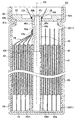
도 1은 제1 실시예에 관한 전지의 종단면도이다.
도 2는 제1 실시예에 관한 축심의 사시도이다.
도 3은 제1 실시예에 관한 축심의 종단면도이다.
도 4는 도 1의 B부 확대도이다.
도 5는 축심에 권회된 권회 전극체의 횡단면도이다.
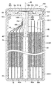
도 6은 제1 실시예의 전지에 있어서의 밸브 개방시의 가스 배출의 모습을 도시하는 도면이다.
도 7은 제1 실시예에 관한 제1 전극판을 도시하는 도면이다.
도 8은 제1 실시예에 관한 제2 전극판을 도시하는 도면이다.
도 9는 제1 실시예에 관한 권회 공정을 설명하는 도면이다.
도 10은 축심에 권회한 권회 전극체의 종단면도이다.
도 11은 제1 실시예에 관한 제1 용접 공정을 설명하는 도면이다.
도 12는 제1 실시예에 관한 수용 공정을 설명하는 도면이다.
도 13은 제1 실시예에 관한 제2 용접 공정을 설명하는 도면이다.
도 14는 제2 실시예에 관한 전지의 종단면도이다.
도 15는 제2 실시예에 관한 축심의 사시도이다.
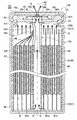
도 16은 제2 실시예의 전지에 있어서의 밸브 개방시의 가스 배출의 모습을 도시하는 도면이다.1 is a longitudinal sectional view of a battery according to the first embodiment.
2 is a perspective view of an axis in accordance with the first embodiment.
3 is a longitudinal sectional view of the shaft center according to the first embodiment.
4 is an enlarged view of a portion B of FIG. 1.
5 is a cross-sectional view of a wound electrode body wound around an axis.
Fig. 6 is a diagram showing a state of gas discharge upon valve opening in the battery of the first embodiment.
7 is a diagram showing a first electrode plate according to the first embodiment.
8 is a diagram showing a second electrode plate according to the first embodiment.
It is a figure explaining the winding process concerning a 1st Example.
It is a longitudinal cross-sectional view of the wound electrode body wound around the shaft center.
11 is a view for explaining a first welding step according to the first embodiment.
It is a figure explaining the accommodation process concerning a 1st Example.
It is a figure explaining the 2nd welding process which concerns on a 1st Example.
14 is a longitudinal sectional view of the battery according to the second embodiment.
15 is a perspective view of an axis in accordance with a second embodiment.
FIG. 16 is a diagram showing a state of gas discharge upon valve opening in the battery of the second embodiment.
(제1 실시예)(First embodiment)
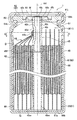
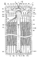
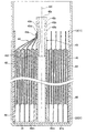
도 1은, 제1 실시예에 관한 전지(1)의 종단면도(축선 AX를 따라 절단한 단면도)이다. 본 제1 실시예의 전지(1)는, 원통 형상의 전지이다(도 1 참조). 이 전지(1)는, 권회 전극체(40)와, 이 권회 전극체(40)를 수용하는 전지 케이스(60)를 갖는다. 이 중, 권회 전극체(40)는, 제1 전극판(10)(정극판)과 제2 전극판(20)(부극판)과 세퍼레이터(30)가, 축심(45)의 외주에 권회된 원통 형상의 권회 전극체이다.1 is a longitudinal cross-sectional view (sectional view taken along the axis AX) of the
또한, 권회 전극체(40)는, 권회수 50의 권회 전극체[제1 전극판(10), 제2 전극판(20) 및 세퍼레이터(30)를 적층한 적층체를, 축심(45)의 주위에 50회 감은 권회 전극체]이지만, 도 1 등에서는, 권회 전극체(40)의 권취수를 간략화(5회 권취로 간략화)하고 있다. 또한, 권회 전극체(40)의 외주면과 전지 케이스(60)[케이스 본체(61)]의 내주면 사이에는, 전기 절연성 수지로 이루어지는 절연 시트(68)가 배치되어 있다.In addition, the
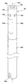
축심(45)은, 도 2 및 도 3에 도시하는 바와 같이, 축선 방향(축선 AX가 연장되는 방향, 도 2 및 도 3에 있어서 상하 방향)으로 연장되는 축 구멍(45j)을 갖는 원통 형상을 이루고 있다. 이 축심(45)은, 금속(예를 들어, 알루미늄)으로 이루어지는 원통 형상의 집전부(45b)와, 수지(예를 들어, 폴리프로필렌)로 이루어지는 원통 형상의 수지부(45f)를 갖고 있다. 상세하게는, 집전부(45b)의 축선 방향 후단부(45c)를, 수지부(45f)의 축선 방향 선단부(45g)의 내측에 압입함으로써, 집전부(45b)와 수지부(45f)를 일체로 하여, 축심(45)을 구성하고 있다(도 3 참조). 또한, 축심(45) 중, 권회 전극체(40)로부터 축선 방향 선단측(도 1에 있어서 상측)으로 돌출되는 부위를 돌출부(45t)로 한다. 본 제1 실시예에서는, 돌출부(45t)는, 집전부(45b)에 의해 구성된다(도 1 내지 도 3 참조).As shown in FIGS. 2 and 3, the
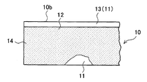
제1 전극판(10)은, 도 7에 도시하는 바와 같이, 제1 집전박(11)이 연장되는 길이 방향(도 7에 있어서 좌우 방향)의 한쪽 변(10b)을 따라 연장되어, 제1 집전박(11) 및 제1 합재층(12)을 갖는 제1 활물질 도포 시공부(14)와, 이 제1 활물질 도포 시공부(14)와 인접하여 길이 방향의 한쪽 변(10b)을 따라 연장되어, 제1 합재층(12)을 갖는 일 없이, 제1 집전박(11)만으로 이루어지는 제1 활물질 미도포 시공부(13)를 갖고 있다.As shown in FIG. 7, the
또한, 제1 집전박(11)으로서는, 예를 들어 알루미늄박을 사용할 수 있다. 또한, 제1 합재층(12)은, 제1 활물질이나 바인더 등에 의해 구성되어 있다. 제1 활물질로서는, 예를 들어 니켈산 리튬을 사용할 수 있다.As the first
제2 전극판(20)은, 도 8에 도시하는 바와 같이, 제2 집전박(21)이 연장되는 길이 방향(도 8에 있어서 좌우 방향)의 한쪽 변(20b)을 따라 연장되어, 제2 집전박(21) 및 제2 합재층(22)을 갖는 제2 활물질 도포 시공부(24)와, 이 제2 활물질 도포 시공부(24)와 인접하여 길이 방향의 한쪽 변(20b)을 따라 연장되어, 제2 합재층(22)을 갖는 일 없이, 제2 집전박(21)만으로 이루어지는 제2 활물질 미도포 시공부(23)를 갖고 있다.As shown in FIG. 8, the
또한, 제2 집전박(21)으로서는, 예를 들어 구리박을 사용할 수 있다. 또한, 제2 합재층(22)은, 제2 활물질이나 바인더 등에 의해 구성되어 있다. 제2 활물질로서는, 예를 들어 천연 흑연을 사용할 수 있다.Moreover, as 2nd electrical
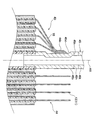
또한, 축선 방향(축선 AX가 연장되는 방향, 도 1에 있어서 상하 방향)에 대해 권회 전극체(40)의 선단부(도 1에 있어서 상단부)를 이루고, 제1 전극판(10)의 제1 활물질 미도포 시공부(13)만이 권회되어 있는 부위를, 제1 권회부(44)로 한다. 또한, 축선 방향에 대해 권회 전극체(40)의 후단부(도 1에 있어서 하단부)를 이루고, 제2 전극판(20)의 제2 활물질 미도포 시공부(23)만이 권회되어 있는 부위를, 제2 권회부(46)로 한다. 또한, 제1 권회부(44)와 제2 권회부(46) 사이에 위치하고, 제1 전극판(10)[제1 활물질 도포 시공부(14)]과 제2 전극판(20)[제2 활물질 도포 시공부(24)]과 세퍼레이터(30)가 권회되어 이루어지는 부위를, 발전부(42)로 한다.Moreover, the front-end | tip part (upper part in FIG. 1) of the rolled
전지 케이스(60)는, 원통형의 전지 케이스이며, 바닥이 있는 원통 형상을 이루는 금속제의 케이스 본체(61)와, 원판 형상을 이루는 금속제의 덮개 부재(62)를 갖는다(도 1 참조). 덮개 부재(62)는, 케이스 본체(61)의 개구(61j)를 폐색하도록 배치되고, 개구(61j)를 구성하는 개구부(61h)의 코킹에 의해, 케이스 본체(61)에 고정되어 있다. 또한, 덮개 부재(62)와 개구부(61h) 사이에는, 전기 절연성 수지로 이루어지는 원환상의 가스킷(69)이 배치되어 있다. 이에 의해, 케이스 본체(61)와 덮개 부재(62) 사이를 전기적으로 절연하면서, 권회 전극체(40)를 수용한 케이스 본체(61)와 덮개 부재(62)가 일체로 되어, 전지 케이스(60)를 이루고 있다.The
덮개 부재(62)는, 축심(45)의 돌출부(45t)가 삽입되는 원통 형상의 삽입 구멍(62b)을 갖는다(도 1 참조). 본 제1 실시예의 전지(1)에서는, 덮개 부재(62)의 삽입 구멍(62b)에 삽입된 축심(45)의 돌출부(45t)[집전부(45b)의 일부]가, 덮개 부재(62)와 용접되어 있다. 이와 같이, 축심(45)의 돌출부(45t)와 덮개 부재(62)를 용접하여, 양자를 전기적으로 접속하고 있으므로, 축심(45)의 집전부(45b)와 덮개 부재(62) 사이의 전기 저항을 작게 할 수 있다. 또한, 도 1에서는, 덮개 부재(62)와 축심(45)의 돌출부(45t)가 용접되어 있는 부위를, 용접부(W)(도 1에 있어서 검게 칠해져 있는 부위)로 하고 있다.The
또한, 후술하는 바와 같이, 축심(45)의 집전부(45b)[집전 접합부(45d)]에는, 제1 권회부(44)[제1 전극판(10)]가 용접되어, 양자가 전기적으로 접속되어 있다. 따라서, 본 제1 실시예의 전지(1)에서는, 덮개 부재(62)[안전 밸브(63)를 포함함]가, 축심(45)의 집전부(45b)를 통해 제1 권회부(44)[제1 전극판(10)]와 전기적으로 접속되어, 제1 외부 단자(정극 외부 단자)로 된다.Moreover, as mentioned later, the 1st winding part 44 (1st electrode plate 10) is welded to the
또한, 제2 권회부(46)[제2 활물질 미도포 시공부(23)]는, 그 단부면(46b)에 있어서, 대략 원판 형상을 이루는 금속제의 제2 집전 부재(72)에 용접되어 있다(도 1 참조). 또한, 제2 집전 부재(72)는, 케이스 본체(61)의 저부(61b)에 용접되어 있다. 이에 의해, 본 제1 실시예의 전지(1)에서는, 케이스 본체(61)의 저부(61b)가, 제2 집전 부재(72)를 통해 제2 권회부(46)[제2 전극판(20)]와 전기적으로 접속되어, 제2 외부 단자(부극 외부 단자)로 된다.Moreover, the 2nd winding part 46 (2nd uncoated part 23) is welded to the metal 2nd electrical
또한, 덮개 부재(62)의 외면 중앙에는, 축선 방향 후단측으로 움푹 들어간 원형의 오목부(62c)가 형성되어 있다(도 1 참조). 이 오목부(62c)의 표면에는, 대략 원판 형상의 안전 밸브(63)가 용접되어 있다. 이 안전 밸브(63)에 의해, 축심(45)[돌출부(45t)]의 선단측 개구(45k)가 폐색된다. 이 안전 밸브(63)는, 전지(1)의 내압[전지 케이스(60)의 내압]이 상승하여 소정의 밸브 개방압에 도달한 경우에, 자신이 개열됨으로써 밸브 개방되도록 형성되어 있다. 안전 밸브(63)가 밸브 개방됨으로써, 전지(1) 내[전지 케이스(60) 내]의 가스를 외부로 배출하여, 전지(1)의 내압[전지 케이스(60)의 내압]의 과승압을 방지한다.Moreover, the circular recessed
여기서, 본 제1 실시예의 전지(1)에 대해, 상세하게 설명한다.Here, the
본 제1 실시예의 축심(45)은, 전술한 바와 같이, 금속(알루미늄)으로 이루어지는 원통 형상의 집전부(45b)를 갖고 있다. 이 집전부(45b)는, 평탄 형상의 집전 접합부(45d)를 포함하고 있다(도 2 및 도 3 참조). 이 집전 접합부(45d)는, 예를 들어 원통 형상의 금속 파이프의 일부[집전 접합부(45d)에 대응하는 부위]를 프레스 성형에 의해 평탄 형상으로 성형한 것이다.As described above, the
또한, 도 4 및 도 5에 도시하는 바와 같이, 본 제1 실시예의 전지(1)에서는, 제1 권회부(44)의 일부를, 집전부(45b)의 집전 접합부(45d)에 접합하고 있다. 상세하게는, 제1 권회부(44) 중, 집전 접합부(45d)에 대해 축심(45)의 직경 방향 외측[도 4 및 도 5에 있어서 집전 접합부(45d)의 좌측]에 위치하는 부위[권회 용접부(44b)라 함]를 겹쳐, 집전 접합부(45d)에 용접(본 제1 실시예에서는, 초음파 용접)하고 있다. 환언하면, 제1 권회부(44) 중, 집전 접합부(45d)에 대해 축심(45)의 직경 방향 외측에 위치하는 부위가, 겹쳐진 상태에서 집전 접합부(45d)에 용접되어 있다. 또한, 도 4는 도 1의 B부 확대도이다. 또한, 도 5는, 축심(45)에 권회된 권회 전극체(40)의 횡단면도이며, 도 1의 C-C 화살표 단면도[도 1의 C-C 절단선의 위치에서 전지(1)를 절단하였을 때의 단면도]에 상당한다.4 and 5, in the
이와 같이, 리드선을 개재시키는 일 없이, 제1 전극판(10)[상세하게는, 제1 권회부(44)]을 직접, 집전부(45b)[집전 접합부(45d)]에 용접함으로써, 제1 전극판(10)과 집전부(45b) 사이의 전기 저항을 작게 할 수 있다.In this manner, the first electrode plate 10 (in detail, the first winding portion 44) is directly welded to the
또한, 본 제1 실시예의 전지(1)에서는, 제1 권회부(44) 중 집전 접합부(45d)에 대해 축심(45)의 직경 방향 외측에 위치하는 부위[권회 용접부(44b)]를 겹치고 있으므로, 제1 전극판(10)과 집전부(45b) 사이의 집전 경로를 짧게 할 수 있고, 또한 집전 경로를 증대[제1 권회부(44)의 권회수 50까지 증대]시킬 수 있다. 이에 의해, 제1 전극판(10)과 집전부(45b) 사이의 전기 저항을 한층 더 작게 할 수 있다.In addition, in the
또한, 도 4 및 도 5에서는, 제1 권회부(44)의 권취수를 간략화(5회 권취로 간략화)하고 있지만, 실제로는, 제1 권회부(44)의 권취수는 50이다. 따라서, 도 4 및 도 5에서는, 4개소의 권회 용접부(44b)만이 나타내어져 있지만, 실제로는, 50개소의 권회 용접부(44b)가 존재한다. 즉, 본 제1 실시예의 전지(1)에서는, 50개소의 권회 용접부(44b)[제1 권회부(44) 중 집전 접합부(45d)에 대해 축심(45)의 직경 방향 외측에 위치하는 부위]를 겹쳐, 집전 접합부(45d)에 용접하고 있다. 환언하면, 50개소의 권회 용접부(44b)가, 겹쳐진 상태에서 집전 접합부(45d)에 용접되어 있다.In addition, although the winding number of the
또한, 본 제1 실시예의 전지(1)에서는, 종래의 전지(예를 들어, 특허문헌 1의 전지)에 비해, 제1 전극판(10)과 집전부(45b) 사이의 전기적 접속에 리드선을 사용하지 않는 만큼, 부품 개수를 삭감할 수 있다. 또한, 본 제1 실시예의 전지(1)에서는, 축심(45)이 집전부(45b)를 포함하고 있으므로[집전부(45b)를 축심(45)의 일부로 하고 있으므로], 종래의 전지(예를 들어, 특허문헌 1의 전지)와 같이, 축심과 집전부(집전판)를 별개의 부품으로 하는 경우에 비해, 부품 개수를 삭감할 수 있다.In addition, in the
또한, 본 제1 실시예의 전지(1)에서는, 전술한 바와 같이, 집전 접합부(45d)가 평탄 형상이다. 이로 인해, 권회 용접부(44b)를 겹쳐 집전 접합부(45d)에 용접할 때, 양자[권회 용접부(44b)와 집전 접합부(45d)]를 적절하게 용접(접합)할 수 있다. 구체적으로는, 후술하는 바와 같이, 초음파 용접에 의해, 권회 용접부(44b)를 집전 접합부(45d)에 용접할 때, 원호 형상의 집전 접합부와 권회 용접부를 압접하는 경우보다도, 평탄 형상의 집전 접합부(45d)와 권회 용접부(44b)를 압접하는 경우의 쪽이, 양자를 적절하게(충분히) 압접할 수 있으므로, 양자를 적절하게(충분히) 용접할 수 있다.In the
다음에, 제1 실시예의 전지(1)에 있어서, 전지(1) 내의 가스를 외부로 배출하는 구조에 대해, 상세하게 설명한다.Next, in the
도 2 및 도 3에 도시하는 바와 같이, 본 제1 실시예의 축심(45)에서는, 자신의 축선 방향 후단부(도 2 및 도 3에 있어서 하단부)에, 자신의 축선 방향 후단(도 2 및 도 3에 있어서 하단)으로부터 축선 방향 선단측(도 2 및 도 3에 있어서 상측)으로 연장되는 형태로, 수지부(45f)를 이루는 벽부를 절결한 절결부(45m)가 2개 형성되어 있다.As shown in FIG. 2 and FIG. 3, in the
이에 의해, 도 6의 하방에 화살표로 나타내는 바와 같이, 권회 전극체(40)의 발전부(42)의 축선 방향 후단측(도 6에 있어서 하단측)으로부터 발전부(42)의 외부[제2 권회부(46)의 간극]로 방출된 가스(G)를, 축심(45)의 절결부(45m)를 통해, 축심(45)의 축 구멍(45j) 내에 도입할 수 있다. 따라서, 전지(1)의 내압[전지 케이스(60)의 내압]이 상승하여 안전 밸브(63)가 밸브 개방(개열)되었을 때에는, 도 6에 화살표로 나타내는 바와 같이, 권회 전극체(40)의 발전부(42)의 축선 방향 후단측으로부터 발전부(42)의 외부[제2 권회부(46)의 간극]로 방출된 가스(G)는, 축심(45)의 축 구멍(45j)을 통해, 밸브 개방된 안전 밸브(63)로부터 전지(1)의 외부로 배출된다.Thereby, as shown by the arrow below FIG. 6, the outside (2nd) of the
그런데, 종래의 전지(예를 들어, 특허문헌 1의 전지)에서는, 권회 전극체의 축선 방향 선단측(상단측)으로부터 권회 전극체의 외부로 방출된 가스를, 축심의 축 구멍 내에 도입할 수 없어, 밸브 개방된 안전 밸브로부터 전지 외부로 배출할 수 없었다. 이로 인해, 안전 밸브가 밸브 개방된 후에도, 전지 내 중 권회 전극체의 축선 방향 선단측(상단측)의 공간 내의 압력을 저하시킬 수 없어, 과승압으로 될 우려가 있었다.By the way, in the conventional battery (for example, the battery of patent document 1), the gas discharged | emitted from the axial direction front end side (upper side) of the wound electrode body to the outside of the wound electrode body can be introduce | transduced into the shaft hole of an axial center. There was no discharge from the battery from the valve open safety valve. For this reason, even after a safety valve was opened, the pressure in the space of the axial direction front end side (upper end side) of the wound electrode body in a battery could not be reduced, and there existed a possibility that it might become overpressure.
이에 대해, 본 제1 실시예의 전지(1)에서는, 도 1 내지 도 3에 도시하는 바와 같이, 축심(45)의 돌출부(45t)가, 덮개 부재(62)보다도 축선 방향 후단측[도 1에 있어서 하측, 권회 전극체(40)측]의 위치[또한, 집전 접합부(45d)보다도 축선 방향 선단측]에서, 돌출부(45t)를 이루는 벽부를 관통하는 관통 구멍(45h)을 갖고 있다. 이 관통 구멍(45h)은, 돌출부(45t)의 주위 방향으로 등간격으로 4개 형성되어 있다.In contrast, in the
이에 의해, 본 제1 실시예의 전지(1)에서는, 도 6의 상방에 화살표로 나타내는 바와 같이, 권회 전극체(40)의 축선 방향 선단측(도 6에 있어서 상단측)으로부터 권회 전극체(40)의 외부로 방출된 가스(G)를, 돌출부(45t)의 관통 구멍(45h)을 통해, 축심(45)의 축 구멍(45j) 내에 도입할 수 있다. 따라서, 전지(1)의 내압[전지 케이스(60)의 내압]이 상승하여 안전 밸브(63)가 밸브 개방(개열)되었을 때에는, 도 6에 화살표로 나타내는 바와 같이, 권회 전극체(40)의 축선 방향 선단측으로부터 권회 전극체(40)의 외부로 방출된 가스(G)를, 축심(45)의 축 구멍(45j)을 통해, 밸브 개방된 안전 밸브(63)로부터 전지(1)의 외부로 배출할 수 있다. 이에 의해, 안전 밸브(63)가 밸브 개방되었을 때에는, 전지(1) 내 중 권회 전극체(40)의 축선 방향 선단측의 공간(S1) 내에 대해서도, 압력을 저하시킬 수 있어, 과승압으로 되는 것을 방지할 수 있다.Thereby, in the
다음에, 제1 실시예에 관한 전지(1)의 제조 방법에 대해, 이하에 설명한다.Next, the manufacturing method of the
우선, 도 7에 도시하는 바와 같이, 띠 형상의 제1 집전박(11)의 표면에 제1 합재층(12)을 형성한 제1 전극판(10)을 준비한다. 이 제1 전극판(10)은, 제1 집전박(11)이 연장되는 길이 방향(도 7에 있어서 좌우 방향)의 한쪽 변(10b)을 따라 연장되어, 제1 집전박(11) 및 제1 합재층(12)을 갖는 제1 활물질 도포 시공부(14)와, 이 제1 활물질 도포 시공부(14)와 인접하여 길이 방향의 한쪽 변(10b)을 따라 연장되어, 제1 합재층(12)을 갖는 일 없이, 제1 집전박(11)만으로 이루어지는 제1 활물질 미도포 시공부(13)를 갖고 있다.First, as shown in FIG. 7, the
또한, 도 8에 도시하는 바와 같이, 띠 형상의 제2 집전박(21)의 표면에 제2 합재층(22)을 형성한 제2 전극판(20)을 준비한다. 이 제2 전극판(20)은, 제2 집전박(21)이 연장되는 길이 방향(도 8에 있어서 좌우 방향)의 한쪽 변(20b)을 따라 연장되어, 제2 집전박(21) 및 제2 합재층(22)을 갖는 제2 활물질 도포 시공부(24)와, 이 제2 활물질 도포 시공부(24)와 인접하여 길이 방향의 한쪽 변(20b)을 따라 연장되어, 제2 합재층(22)을 갖는 일 없이, 제2 집전박(21)만으로 이루어지는 제2 활물질 미도포 시공부(23)를 갖고 있다.As shown in FIG. 8, the
다음에, 적층 공정에 있어서, 제2 전극판(20), 세퍼레이터(30), 제1 전극판(10) 및 세퍼레이터(30)를, 이 순서로 적층한다(도 9 참조). 구체적으로는, 제1 전극판(10)의 제1 활물질 미도포 시공부(13)와 제2 전극판(20)의 제2 활물질 미도포 시공부(23)가, 폭 방향(도 9에 있어서 상하 방향)에서 서로 배향하는 방향이며, 제1 활물질 미도포 시공부(13)가 세퍼레이터(30) 및 제2 전극판(20)과 겹쳐지지 않도록, 또한 제2 활물질 미도포 시공부(23)가 세퍼레이터(30) 및 제1 전극판(10)과 겹쳐지지 않도록 적층한다.Next, in the lamination step, the
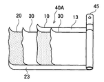
이어서, 권회 공정으로 진행하여, 도 9에 도시하는 바와 같이, 제2 전극판(20), 제1 전극판(10) 및 세퍼레이터(30)를 적층한 적층체(40A)를, 원통 형상의 축심(45)의 주위에 권회한다. 이에 의해, 원통 형상의 권회 전극체(40)를 형성할 수 있다(도 10 참조). 또한, 본 제1 실시예에서는, 적층체(40A)를, 축심(45)의 주위에 50회 권회하였다.Subsequently, it progresses to a winding process and as shown in FIG. 9, 40 A of laminated bodies which laminated | stacked the
그 후, 제2 권회부(46)에 제2 집전 부재(72)를 용접하였다(도 10 참조). 구체적으로는, 제2 집전 부재(72)에, 제2 권회부(46)의 단부면(46b)을 접촉한 상태에서, 제2 집전 부재(72)의 표면에 레이저 빔을 조사하여, 제2 권회부(46)와 제2 집전 부재(72)를 레이저 용접하였다.Thereafter, the second current collecting
다음에, 제1 용접 공정으로 진행하여, 초음파 용접에 의해, 권회 용접부(44b)를 집전 접합부(45d)에 용접하였다. 구체적으로는, 도 11에 도시하는 바와 같이, 앤빌(82)을 축심(45)[집전부(45b)]의 축 구멍(45j) 내에 삽입하고, 앤빌(82)의 압박부(82b)를 축심(45)의 집전 접합부(45d)의 내면(평탄면)에 접촉시킨다. 또한, 초음파 혼(81)의 압박부(81b)에 의해, 제1 권회부(44)의 권회 용접부(44b)[집전 접합부(45d)에 대해 축심(45)의 직경 방향 외측에 위치하는 부위, 도 5 참조]를 직경 방향 내측에 겹치는 동시에, 겹친 권회 용접부(44b)를 축심(45)의 집전 접합부(45d)의 외면(평탄면)에 압접한다. 이 상태에서, 초음파 혼(81)의 압박부(81b)를 초음파 진동시켜, 권회 용접부(44b)를 집전 접합부(45d)에 용접하였다.Next, it progressed to the 1st welding process, and the
이와 같이, 리드선을 개재시키는 일 없이, 제1 전극판(10)[상세하게는, 제1 권회부(44)]을 직접, 집전부(45b)[집전 접합부(45d)]에 용접함으로써, 제1 전극판(10)과 집전부(45b) 사이의 전기 저항을 작게 할 수 있다.In this manner, the first electrode plate 10 (in detail, the first winding portion 44) is directly welded to the
또한, 제1 용접 공정에서는, 제1 권회부(44) 중 집전 접합부(45d)에 대해 축심(45)의 직경 방향 외측에 위치하는 부위[권회 용접부(44b)]를 겹치고 있으므로, 제1 전극판(10)과 집전부(45b) 사이의 집전 경로를 짧게 할 수 있고, 또한 집전 경로를 증대[제1 권회부(44)의 권회수 50까지 증대]시킬 수 있다. 이에 의해, 제1 전극판(10)과 집전부(45b) 사이의 전기 저항을 한층 더 작게 할 수 있다.In addition, in the 1st welding process, since the site | part (
또한, 본 제1 실시예에서는, 집전 접합부(45d)를 평탄 형상으로 하고 있다. 이에 의해, 제1 용접 공정에 있어서, 권회 용접부(44b)와 집전 접합부(45d)를 적절하게 용접(접합)할 수 있다. 구체적으로는, 상술한 바와 같이, 초음파 혼(81)과 앤빌(82)을 사용하여, 권회 용접부(44b)와 집전 접합부(45d)를 초음파 용접할 때, 앤빌(82)의 압박부(82b)와 초음파 혼(81)의 압박부(81b)에 의해, 원호 형상의 집전 접합부와 권회 용접부를 압접하는 경우보다도, 평탄 형상의 집전 접합부(45d)와 권회 용접부(44b)를 압접하는 경우의 쪽이, 양자를 적절하게(충분히) 압접할 수 있으므로, 양자를 적절하게(충분히) 용접할 수 있다.In the first embodiment, the current
다음에, 수용 공정으로 진행하여, 도 12에 도시하는 바와 같이, 축심(45)의 외주에 권회하여 이루어지는 권회 전극체(40)를, 축심(45)과 함께 케이스 본체(61)의 내부에 수용한다. 이때, 제2 권회부(46)에 용접되어 있는 제2 집전 부재(72)는, 케이스 본체(61)의 저부(61b)에 접한다. 또한, 권회 전극체(40)를 케이스 본체(61)의 내부에 수용하는 것에 앞서, 권회 전극체(40)의 외주에 절연 시트(68)를 권회해 둔다.Next, the process proceeds to the housing step, and as illustrated in FIG. 12, the
그 후, 제2 집전 부재(72)를 케이스 본체(61)의 저부(61b)에 용접한다. 구체적으로는, 케이스 본체(61)의 저부(61b)의 외표면에 레이저 빔을 조사하여, 제2 집전 부재(72)와 케이스 본체(61)의 저부(61b)를 레이저 용접하였다. 이에 의해, 케이스 본체(61)의 저부(61b)가, 제2 집전 부재(72)를 통해 제2 권회부(46)[제2 전극판(20)]와 전기적으로 접속되어, 제2 외부 단자로 된다.Thereafter, the second current collecting
다음에, 도 13에 도시하는 바와 같이, 케이스 본체(61)의 축선 방향 선단측(도 13에 있어서 상측)의 일부를, 케이스 본체(61)의 전체 둘레에 걸쳐 직경 방향 내측(축선 AX측)으로 변형시켜, 환 형상 단차부(61k)를 형성한다. 그 후, 케이스 본체(61)의 개구부(61h)의 내측에, 원환상의 가스킷(69)을 배치한다. 또한, 가스킷(69)은, 환 형상 단차부(61k) 상에 적재됨으로써, 케이스 본체(61)에 대해 위치 결정된다.Next, as shown in FIG. 13, a part of the axial direction front end side (upper side in FIG. 13) of the case
계속해서, 배치 공정으로 진행하여, 덮개 부재(62)의 삽입 구멍(62b)에 축심(45)의 돌출부(45t)를 삽입시키도록 하여, 덮개 부재(62)를 케이스 본체(61)의 개구(61j)의 내측[상세하게는, 가스킷(69)의 내측]에 배치한다. 또한, 덮개 부재(62)는, 가스킷(69)의 단차부(69b) 상에 적재됨으로써, 케이스 본체(61)에 대해 위치 결정된다.Subsequently, the process proceeds to the arranging step so that the
다음에, 제2 용접 공정으로 진행하여, 덮개 부재(62)의 삽입 구멍(62b)에 삽입된 축심(45)의 돌출부(45t)를, 덮개 부재(62)와 용접한다. 구체적으로는, 도 13에 도시하는 바와 같이, 덮개 부재(62)의 외측으로부터, 돌출부(45t)의 전체 둘레에 걸쳐 레이저 빔(LB)을 조사하여, 덮개 부재(62)와 축심(45)[돌출부(45t)]을 레이저 용접한다. 이와 같이, 축심(45)의 돌출부(45t)와 덮개 부재(62)(제1 외부 단자)를 용접하여, 양자를 전기적으로 접속함으로써, 양자간의 전기 저항을 작게 할 수 있다. 또한, 축심(45)[돌출부(45t)]을 덮개 부재(62)에 전체 둘레 용접함으로써, 덮개 부재(62)의 삽입 구멍(62b)이 밀봉된다.Next, it progresses to a 2nd welding process, and the
이어서, 케이스 본체(61)의 개구(61j)를 구성하는 개구부(61h)를 코킹하여, 가스킷(69)과 함께 덮개 부재(62)를, 케이스 본체(61)에 고정한다(도 1 참조). 이에 의해, 케이스 본체(61)와 덮개 부재(62) 사이를 가스킷(69)에 의해 전기적으로 절연하면서, 케이스 본체(61)와 덮개 부재(62)가 일체로 되어, 전지 케이스(60)가 형성된다. 그 후, 축심(45)의 선단측 개구(45k)를 통해, 케이스 본체(61)의 내부에 전해액을 주입한다. 그 후, 덮개 부재(62)의 오목부(62c)의 표면에, 안전 밸브(63)를 전체 둘레 용접한다. 이에 의해, 축심(45)의 선단측 개구(45k)가 폐색되어, 밀폐형 전지(1)가 완성된다.Next, the
(제2 실시예)(2nd Example)
다음에, 제2 실시예에 관한 전지(100)에 대해 설명한다. 본 제2 실시예의 전지(100)는, 제1 실시예의 전지(1)와 비교하여, 축심의 집전부의 형상이 다르고, 그 밖에 대해서는 제1 실시예와 마찬가지이다. 따라서, 여기서는, 제1 실시예와 다른 점을 중심으로 설명하고, 마찬가지인 점에 대해서는 설명을 생략 또는 간략화한다.Next, the
도 14는, 제2 실시예에 관한 전지(100)의 종단면도(축선 AX를 따라 절단한 단면도)이다. 본 제2 실시예의 전지(100)는, 제1 실시예의 축심(45) 대신에, 축심(145)을 구비하고 있다. 또한, 권회 전극체(40)는, 권회수 50의 권회 전극체이지만, 도 14 등에서는, 권회 전극체(40)의 권취수를 간략화(5회 권취로 간략화)하고 있다.14 is a longitudinal sectional view (sectional view taken along the axis AX) of the
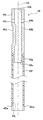
축심(145)은, 도 15에 도시하는 바와 같이, 금속(예를 들어, 알루미늄)으로 이루어지는 원통 형상의 집전부(145b)와, 수지(예를 들어, 폴리프로필렌)로 이루어지는 원통 형상의 수지부(45f)를 갖고 있다. 이 중, 집전부(145b)[상세하게는, 돌출부(145t)]는, 제1 실시예의 집전부(45b)[돌출부(45t)]와 달리, 자신의 선단(축선 방향 선단, 도 14 및 도 15에 있어서 상단)으로부터 덮개 부재(62)보다도 축선 방향 후단측[권회 전극체(40)측, 도 14에 있어서 하방]의 위치까지 돌출부(145t)를 이루는 벽부를 절결한 절결부(145h)를 갖고 있다. 환언하면, 본 제2 실시예의 돌출부(145t)에는, 제1 실시예의 관통 구멍(45h) 대신에, 절결부(145h)가 형성되어 있다. 또한, 절결부(145h)는, 돌출부(145t)의 직경 방향에 대향하는 위치에 총 2개 형성되어 있다.As shown in FIG. 15, the
이에 의해, 본 제2 실시예의 전지(100)에서는, 도 16의 상방에 화살표로 나타내는 바와 같이, 권회 전극체(40)의 축선 방향 선단측(도 16에 있어서 상단측)으로부터 권회 전극체(40)의 외부로 방출된 가스(G)를, 돌출부(145t)의 절결부(145h)를 통해, 축심(145)의 축 구멍(145j) 내에 도입할 수 있다. 따라서, 전지(100)의 내압[전지 케이스(60)의 내압]이 상승하여 안전 밸브(63)가 밸브 개방(개열)되었을 때에는, 도 16에 화살표로 나타내는 바와 같이, 권회 전극체(40)의 축선 방향 선단측으로부터 권회 전극체(40)의 외부로 방출된 가스(G)를, 축심(145)의 축 구멍(145j)을 통해, 밸브 개방된 안전 밸브(63)로부터 전지(100)의 외부로 배출할 수 있다. 이에 의해, 안전 밸브(63)가 밸브 개방되었을 때에는, 전지(100) 내 중 권회 전극체(40)의 축선 방향 선단측의 공간(S1) 내에 대해서도, 압력을 저하시킬 수 있어, 과승압으로 되는 것을 방지할 수 있다.As a result, in the
또한, 도 16의 하방에 화살표로 나타내는 바와 같이, 권회 전극체(40)의 발전부(42)의 축선 방향 후단측(도 16에 있어서 하단측)으로부터 발전부(42)의 외부[제2 권회부(46)의 간극]로 방출된 가스(G)를, 축심(145)의 절결부(45m)를 통해, 축심(145)의 축 구멍(145j) 내에 도입할 수 있다. 따라서, 전지(100)의 내압[전지 케이스(60)의 내압]이 상승하여 안전 밸브(63)가 밸브 개방(개열)되었을 때에는, 도 16에 화살표로 나타내는 바와 같이, 권회 전극체(40)의 발전부(42)의 축선 방향 후단측으로부터 발전부(42)의 외부[제2 권회부(46)의 간극]로 방출된 가스(G)에 대해서도, 축심(145)의 축 구멍(145j)을 통해, 밸브 개방된 안전 밸브(63)로부터 전지(100)의 외부로 배출할 수 있다.Moreover, as shown by the arrow below FIG. 16, the outer side of the
또한, 본 제2 실시예의 전지(100)에서도, 제1 실시예의 전지(1)와 마찬가지로, 제1 권회부(44) 중, 집전 접합부(45d)에 대해 축심(145)의 직경 방향 외측[도 14에 있어서 집전 접합부(45d)의 좌측]에 위치하는 부위[권회 용접부(44b)]를 겹쳐, 집전 접합부(45d)에 용접(본 제2 실시예에서도, 초음파 용접)하고 있다. 환언하면, 제1 권회부(44) 중, 집전 접합부(45d)에 대해 축심(145)의 직경 방향 외측에 위치하는 부위가, 겹쳐진 상태에서 집전 접합부(45d)에 용접되어 있다.In addition, also in the
이와 같이, 리드선을 개재시키는 일 없이, 제1 전극판(10)[상세하게는, 제1 권회부(44)]을 직접, 집전부(145b)[집전 접합부(45d)]에 용접함으로써, 제1 전극판(10)과 집전부(145b) 사이의 전기 저항을 작게 할 수 있다.In this manner, the first electrode plate 10 (in detail, the first winding portion 44) is directly welded to the
또한, 제1 권회부(44) 중 집전 접합부(45d)에 대해 축심(145)의 직경 방향 외측에 위치하는 부위[권회 용접부(44b)]를 겹치고 있으므로, 제1 전극판(10)과 집전부(145b) 사이의 집전 경로를 짧게 할 수 있고, 또한 집전 경로를 증대[제1 권회부(44)의 권회수 50까지 증대]시킬 수 있다. 이에 의해, 제1 전극판(10)과 집전부(145b) 사이의 전기 저항을 한층 더 작게 할 수 있다.Moreover, since the part (
또한, 본 제2 실시예의 전지(100)에서도, 종래의 전지(예를 들어, 특허문헌 1의 전지)에 비해, 제1 전극판(10)과 집전부(145b) 사이의 전기적 접속에 리드선을 사용하지 않는 만큼, 부품 개수를 삭감할 수 있다. 또한, 본 제2 실시예의 전지(100)에서도, 축심(145)이 집전부(145b)를 포함하고 있으므로[집전부(145b)를 축심(145)의 일부로 하고 있으므로], 종래의 전지(예를 들어, 특허문헌 1의 전지)와 같이, 축심과 집전부(집전판)를 별개의 부품으로 하는 경우에 비해, 부품 개수를 삭감할 수 있다.In addition, also in the
또한, 본 제2 실시예의 전지(100)에서도, 집전 접합부(45d)를 평탄 형상으로 하고 있다. 이로 인해, 권회 용접부(44b)를 겹쳐 집전 접합부(45d)에 용접할 때, 양자[권회 용접부(44b)와 집전 접합부(45d)]를 적절하게 용접(접합)할 수 있다. 구체적으로는, 초음파 용접에 의해, 권회 용접부(44b)를 집전 접합부(45d)에 용접할 때, 앤빌(82)의 압박부(82b)와 초음파 혼(81)의 압박부(81b)에 의해, 원호 형상의 집전 접합부와 권회 용접부를 압접하는 경우보다도, 평탄 형상의 집전 접합부(45d)와 권회 용접부(44b)를 압접하는 경우의 쪽이, 양자를 적절하게(충분히) 압접할 수 있으므로, 양자를 적절하게(충분히) 용접할 수 있다.Also, in the
이상에 있어서, 본 발명을 제1, 제2 실시예에 입각하여 설명하였지만, 본 발명은 상기 실시예에 한정되는 것은 아니며, 그 요지를 일탈하지 않는 범위에서, 적절하게 변경하여 적용할 수 있는 것은 물론이다.As mentioned above, although this invention was demonstrated based on the 1st, 2nd Example, this invention is not limited to the said Example, It is possible to change suitably and to apply in the range which does not deviate from the summary. Of course.
1, 100 : 전지
10 : 제1 전극판
13 : 제1 활물질 미도포 시공부
20 : 제2 전극판
23 : 제2 활물질 미도포 시공부
30 : 세퍼레이터
40 : 권회 전극체
42 : 발전부
44 : 제1 권회부
45, 145 : 축심
45b, 145b : 집전부
45d : 집전 접합부
45h : 관통 구멍
45j, 145j : 축 구멍
45t, 145t : 돌출부
46 : 제2 권회부
61 : 케이스 본체
62 : 덮개 부재
62b : 삽입 구멍
63 : 안전 밸브
145h : 절결부1, 100: battery
10: first electrode plate
13: uncoated portion of the first active material
20: second electrode plate
23: uncoated portion of the second active material
30: Separator
40: wound electrode body
42: power generation unit
44: the first roll
45, 145: center of gravity
45b, 145b: current collector
45d: current collector junction
45h: through hole
45j, 145j: shaft hole
45t, 145t: protrusion
46: the second winding department
61 case body
62: cover member
62b: insertion hole
63: safety valve
145h: cutout
Claims (3)
제1 전극판, 제2 전극판 및 세퍼레이터를 상기 축심의 외주에 권회하여 이루어지는 권회 전극체이며,
상기 축선 방향에 대해 상기 권회 전극체의 선단부를 이루고, 상기 제1 전극판의 제1 활물질 미도포 시공부가 권회되어 이루어지는 제1 권회부,
상기 축선 방향에 대해 상기 권회 전극체의 후단부를 이루고, 상기 제2 전극판의 제2 활물질 미도포 시공부가 권회되어 이루어지는 제2 권회부 및
상기 축선 방향에 대해 상기 제1 권회부와 상기 제2 권회부 사이에 위치하고, 상기 제1 전극판과 상기 제2 전극판과 상기 세퍼레이터가 권회되어 이루어지는 발전부를 갖는 권회 전극체를 구비하는 전지이며,
상기 축심은, 금속제의 집전부이며, 상기 제1 권회부 또는 상기 제2 권회부와 접합하는 집전 접합부를 포함하는 집전부를 갖고,
상기 제1 권회부 또는 상기 제2 권회부 중 상기 집전 접합부에 대해 상기 축심의 직경 방향 외측에 위치하는 부위를 겹쳐, 상기 집전 접합부에 용접하여 이루어지는, 전지.A cylindrical shaft having an axial hole extending in the axial direction,
It is a wound electrode body formed by winding a first electrode plate, a second electrode plate, and a separator on the outer periphery of the shaft core,
The first winding part which forms the front-end | tip of the said winding electrode body with respect to the said axial direction, and the 1st active material uncoated part of the said 1st electrode plate is wound,
A second winding portion formed of a rear end of the wound electrode body with respect to the axial direction, and a second uncoated portion of the second electrode plate being uncoated;
It is a battery provided with the wound electrode body which is located between the said 1st winding part and the said 2nd winding parts with respect to the said axial direction, and has a power generation part by which the said 1st electrode plate, the said 2nd electrode plate, and the said separator are wound,
The shaft center is a metal current collector, and has a current collector including a current collector joint that is joined to the first wound part or the second wound part,
The battery formed by overlapping the site | part located in the radial direction outer side of the said shaft center with respect to the said electrical power collector junction part among the said 1st winding part or said 2nd winding part, and welding to the said electrical power collector junction part.
상기 케이스 본체의 개구를 폐색하는 덮개 부재이며, 상기 권회 전극체가 권회되어 이루어지는 상기 축심 중 상기 권회 전극체로부터 축선 방향 선단측으로 돌출되는 돌출부가 삽입되는 삽입 구멍을 갖는 덮개 부재와,
상기 돌출부의 선단측 개구를 폐색하는 안전 밸브이며, 상기 전지의 내압이 소정의 밸브 개방압에 도달한 경우에 밸브 개방하여, 상기 전지 내에 있어서 상기 축심의 상기 축 구멍 내에 도입된 가스를, 상기 축 구멍을 통해 당해 안전 밸브로부터 전지 외부로 배출하는 안전 밸브를 구비하고,
상기 축심의 상기 돌출부는, 상기 덮개 부재보다도 상기 축선 방향 후단측의 위치에서 당해 돌출부를 이루는 벽부를 관통하는 관통 구멍, 또는 자신의 선단으로부터 상기 덮개 부재보다도 상기 축선 방향 후단측의 위치까지 당해 돌출부를 이루는 벽부를 절결한 절결부를 갖는, 전지.
The bottom-shaped cylindrical case body for accommodating the wound electrode body according to claim 1 or 2,
A lid member for closing an opening of the case body, the lid member having an insertion hole into which a protrusion which protrudes from the wound electrode body to an axially distal end side of the shaft core in which the wound electrode body is wound is inserted;
A safety valve for closing the tip side opening of the protruding portion, wherein the valve is opened when the internal pressure of the battery reaches a predetermined valve opening pressure, and the gas introduced into the shaft hole of the shaft center in the battery is stored in the shaft. A safety valve which discharges from the safety valve to the outside of the battery through the hole;
The protruding portion of the shaft core is a through hole penetrating through the wall portion constituting the protruding portion at a position at the rear end side of the axial direction than the lid member, or the protruding portion from its own end to a position at the rear end side of the axial direction than the lid member. The battery which has the notch part which cut out the wall part which comprises.
Applications Claiming Priority (3)
| Application Number | Priority Date | Filing Date | Title |
|---|---|---|---|
| JP2009294134A JP4780231B2 (en) | 2009-12-25 | 2009-12-25 | battery |
| JPJP-P-2009-294134 | 2009-12-25 | ||
| PCT/JP2010/061597 WO2011077775A1 (en) | 2009-12-25 | 2010-07-08 | Battery |
Publications (2)
| Publication Number | Publication Date |
|---|---|
| KR20120052902A true KR20120052902A (en) | 2012-05-24 |
| KR101166661B1 KR101166661B1 (en) | 2012-07-18 |
Family
ID=44195324
Family Applications (1)
| Application Number | Title | Priority Date | Filing Date |
|---|---|---|---|
| KR1020117030459A Active KR101166661B1 (en) | 2009-12-25 | 2010-07-08 | Battery |
Country Status (5)
| Country | Link |
|---|---|
| US (1) | US8852771B2 (en) |
| JP (1) | JP4780231B2 (en) |
| KR (1) | KR101166661B1 (en) |
| CN (1) | CN102549810A (en) |
| WO (1) | WO2011077775A1 (en) |
Cited By (1)
| Publication number | Priority date | Publication date | Assignee | Title |
|---|---|---|---|---|
| US10256455B2 (en) | 2015-10-02 | 2019-04-09 | Samsung Sdi Co., Ltd. | Secondary battery |
Families Citing this family (21)
| Publication number | Priority date | Publication date | Assignee | Title |
|---|---|---|---|---|
| JP5510051B2 (en) * | 2010-05-13 | 2014-06-04 | トヨタ自動車株式会社 | Battery, vehicle and battery-equipped equipment |
| JP5598988B2 (en) * | 2011-01-21 | 2014-10-01 | 日立オートモティブシステムズ株式会社 | Winding battery |
| JP6127967B2 (en) * | 2011-02-24 | 2017-05-17 | 日立化成株式会社 | Secondary battery and lithium ion battery |
| US9356264B2 (en) | 2012-04-26 | 2016-05-31 | Medtronic, Inc. | Electrode assemblies including a mandrel and at least one insulative portion |
| US8778521B2 (en) | 2012-04-26 | 2014-07-15 | Medtronic, Inc. | Mandrel for electrode assemblies |
| US9130223B2 (en) | 2012-04-26 | 2015-09-08 | Medtronic, Inc. | Mandrel for electrode assemblies |
| KR102069150B1 (en) * | 2013-03-26 | 2020-01-23 | 에스케이이노베이션 주식회사 | Current Collector for Battery and Secondary Battery Comprising the Same |
| CN103579669B (en) * | 2013-11-22 | 2015-08-05 | 江苏风迅新能源科技有限公司 | A kind of high-capacity cylindrical or rectangular lithium ion battery |
| WO2015098865A1 (en) * | 2013-12-26 | 2015-07-02 | 新神戸電機株式会社 | Capacitor |
| KR102262668B1 (en) | 2014-01-28 | 2021-06-09 | 리튬 웍스 테크놀로지 비.브이. | Cylindrical electrochemical cells and method of manufacture |
| CN104577190A (en) * | 2014-12-30 | 2015-04-29 | 山东精工电子科技有限公司 | Steel-shell cylindrical lithium ion battery and preparation method thereof |
| KR102417637B1 (en) * | 2015-10-02 | 2022-07-06 | 삼성에스디아이 주식회사 | A secondary battery |
| KR102355109B1 (en) * | 2017-12-21 | 2022-01-25 | 주식회사 엘지에너지솔루션 | Cylindrical Secondary Battery Having Pilar for Welding |
| WO2019218283A1 (en) * | 2018-05-16 | 2019-11-21 | 深圳前海优容科技有限公司 | Battery and electronic device |
| KR102480958B1 (en) * | 2018-10-05 | 2022-12-23 | 주식회사 엘지에너지솔루션 | Rechargeable battery |
| CN111244381A (en) * | 2020-03-05 | 2020-06-05 | 清华大学 | An all-tab type button battery and its manufacturing method |
| JPWO2022181338A1 (en) * | 2021-02-26 | 2022-09-01 | ||
| CN116897460B (en) * | 2021-12-01 | 2025-09-16 | 宁德时代新能源科技股份有限公司 | Battery cell, battery, electric equipment and manufacturing method and equipment of battery cell |
| EP4235885A1 (en) * | 2022-02-23 | 2023-08-30 | Branson Ultraschall Niederlassung der Emerson Technologies GmbH & Co. oHG | Manufacturing method of an intermediate product for a battery cell, intermediate product for a battery cell and ultrasonic device for manufacturing the intermediate product |
| JP2024015927A (en) * | 2022-07-25 | 2024-02-06 | 株式会社村田製作所 | secondary battery |
| WO2025204963A1 (en) * | 2024-03-27 | 2025-10-02 | パナソニックIpマネジメント株式会社 | Secondary battery |
Family Cites Families (12)
| Publication number | Priority date | Publication date | Assignee | Title |
|---|---|---|---|---|
| US5523178A (en) * | 1992-12-14 | 1996-06-04 | Nippondenso Co., Ltd. | Chemical cell |
| JP4192291B2 (en) * | 1998-06-16 | 2008-12-10 | 株式会社デンソー | Wound electrode battery |
| JP3733403B2 (en) * | 1999-02-04 | 2006-01-11 | トヨタ自動車株式会社 | Electrode wound type battery |
| JP2000268803A (en) * | 1999-03-19 | 2000-09-29 | Nec Corp | Non-aqueous electrolyte secondary battery |
| JP4003377B2 (en) * | 2000-06-14 | 2007-11-07 | 新神戸電機株式会社 | Non-aqueous electrolyte secondary battery |
| JP3627645B2 (en) | 2000-10-24 | 2005-03-09 | 新神戸電機株式会社 | Lithium secondary battery |
| JP2002222666A (en) * | 2001-01-25 | 2002-08-09 | Ngk Insulators Ltd | Lithium secondary battery |
| JP4433650B2 (en) * | 2001-10-03 | 2010-03-17 | 日本碍子株式会社 | Lithium secondary cell and connection structure of lithium secondary cell |
| JP4207451B2 (en) | 2002-04-19 | 2009-01-14 | パナソニック株式会社 | Cylindrical lithium ion secondary battery and manufacturing method thereof |
| JP4315231B2 (en) | 2008-01-22 | 2009-08-19 | トヨタ自動車株式会社 | Battery manufacturing method |
| JP2009181812A (en) * | 2008-01-30 | 2009-08-13 | Toyota Motor Corp | Winding type battery and manufacturing method thereof |
| KR100971744B1 (en) * | 2008-05-07 | 2010-07-21 | 삼성에스디아이 주식회사 | Secondary battery |
-
2009
- 2009-12-25 JP JP2009294134A patent/JP4780231B2/en active Active
-
2010
- 2010-07-08 KR KR1020117030459A patent/KR101166661B1/en active Active
- 2010-07-08 CN CN201080042825XA patent/CN102549810A/en active Pending
- 2010-07-08 US US13/376,930 patent/US8852771B2/en active Active
- 2010-07-08 WO PCT/JP2010/061597 patent/WO2011077775A1/en not_active Ceased
Cited By (1)
| Publication number | Priority date | Publication date | Assignee | Title |
|---|---|---|---|---|
| US10256455B2 (en) | 2015-10-02 | 2019-04-09 | Samsung Sdi Co., Ltd. | Secondary battery |
Also Published As
| Publication number | Publication date |
|---|---|
| KR101166661B1 (en) | 2012-07-18 |
| US8852771B2 (en) | 2014-10-07 |
| CN102549810A (en) | 2012-07-04 |
| US20120251854A1 (en) | 2012-10-04 |
| WO2011077775A1 (en) | 2011-06-30 |
| JP2011134641A (en) | 2011-07-07 |
| JP4780231B2 (en) | 2011-09-28 |
Similar Documents
| Publication | Publication Date | Title |
|---|---|---|
| KR101166661B1 (en) | Battery | |
| JP5590391B2 (en) | Secondary battery | |
| JP4436587B2 (en) | Battery and battery pack | |
| JP6093874B2 (en) | Prismatic secondary battery | |
| JP5011664B2 (en) | Sealed secondary battery | |
| JP5081932B2 (en) | Sealed battery and manufacturing method thereof | |
| JP5337586B2 (en) | Sealed battery and method for manufacturing sealed battery | |
| JP2016225014A (en) | Cylindrical secondary battery | |
| EP2136425A1 (en) | Rechargeable Battery and Manufacturing Method thereof | |
| JP5418261B2 (en) | Battery and manufacturing method thereof | |
| JP6729137B2 (en) | Secondary battery, manufacturing method thereof, and assembled battery using the same | |
| JP7088008B2 (en) | Secondary battery and its manufacturing method | |
| CN115275455A (en) | Battery cell structure, manufacturing method of battery cell structure, battery and vehicle | |
| JP6935798B2 (en) | How to manufacture a secondary battery | |
| JP2016091670A (en) | Cylindrical secondary battery | |
| JPWO2020137714A1 (en) | Rechargeable battery | |
| KR101173865B1 (en) | Rechargeable battery | |
| KR101257633B1 (en) | Method for manufacturing battery | |
| JP2001155711A (en) | Electric energy storage device | |
| JP7443321B2 (en) | Secondary batteries and assembled batteries, and their manufacturing methods | |
| JP2018101568A (en) | Square secondary battery and manufacturing method thereof | |
| JP2005071677A (en) | Battery and battery unit using this | |
| JP6133680B2 (en) | Prismatic secondary battery | |
| JP5158435B2 (en) | Battery and manufacturing method thereof | |
| JP2001118561A (en) | Current collecting structure and secondary battery |
Legal Events
| Date | Code | Title | Description |
|---|---|---|---|
| A201 | Request for examination | ||
| A302 | Request for accelerated examination | ||
| PA0105 | International application |
Patent event date: 20111220 Patent event code: PA01051R01D Comment text: International Patent Application |
|
| PA0201 | Request for examination |
Patent event code: PA02012R01D Patent event date: 20111220 Comment text: Request for Examination of Application |
|
| PA0302 | Request for accelerated examination |
Patent event date: 20111220 Patent event code: PA03022R01D Comment text: Request for Accelerated Examination |
|
| PG1501 | Laying open of application | ||
| E701 | Decision to grant or registration of patent right | ||
| PE0701 | Decision of registration |
Patent event code: PE07011S01D Comment text: Decision to Grant Registration Patent event date: 20120628 |
|
| GRNT | Written decision to grant | ||
| PR0701 | Registration of establishment |
Comment text: Registration of Establishment Patent event date: 20120711 Patent event code: PR07011E01D |
|
| PR1002 | Payment of registration fee |
Payment date: 20120711 End annual number: 3 Start annual number: 1 |
|
| PG1601 | Publication of registration | ||
| FPAY | Annual fee payment |
Payment date: 20150618 Year of fee payment: 4 |
|
| PR1001 | Payment of annual fee |
Payment date: 20150618 Start annual number: 4 End annual number: 4 |
|
| FPAY | Annual fee payment |
Payment date: 20160617 Year of fee payment: 5 |
|
| PR1001 | Payment of annual fee |
Payment date: 20160617 Start annual number: 5 End annual number: 5 |
|
| FPAY | Annual fee payment |
Payment date: 20170616 Year of fee payment: 6 |
|
| PR1001 | Payment of annual fee |
Payment date: 20170616 Start annual number: 6 End annual number: 6 |
|
| FPAY | Annual fee payment |
Payment date: 20180619 Year of fee payment: 7 |
|
| PR1001 | Payment of annual fee |
Payment date: 20180619 Start annual number: 7 End annual number: 7 |
|
| PR1001 | Payment of annual fee |
Payment date: 20200622 Start annual number: 9 End annual number: 9 |
|
| PR1001 | Payment of annual fee |
Payment date: 20220620 Start annual number: 11 End annual number: 11 |
|
| PR1001 | Payment of annual fee |
Payment date: 20230620 Start annual number: 12 End annual number: 12 |
|
| PR1001 | Payment of annual fee |
Payment date: 20240620 Start annual number: 13 End annual number: 13 |
|
| PR1001 | Payment of annual fee |
Payment date: 20250618 Start annual number: 14 End annual number: 14 |