KR20120052317A - Support for filiform elements containing an active material - Google Patents
Support for filiform elements containing an active material Download PDFInfo
- Publication number
- KR20120052317A KR20120052317A KR1020127003874A KR20127003874A KR20120052317A KR 20120052317 A KR20120052317 A KR 20120052317A KR 1020127003874 A KR1020127003874 A KR 1020127003874A KR 20127003874 A KR20127003874 A KR 20127003874A KR 20120052317 A KR20120052317 A KR 20120052317A
- Authority
- KR
- South Korea
- Prior art keywords
- support
- lamp
- philippine
- powder
- active material
- Prior art date
Links
- 239000011149 active material Substances 0.000 title claims abstract description 35
- 230000000903 blocking effect Effects 0.000 claims abstract description 37
- 239000000843 powder Substances 0.000 claims abstract description 32
- 239000000463 material Substances 0.000 claims description 24
- QSHDDOUJBYECFT-UHFFFAOYSA-N mercury Chemical compound [Hg] QSHDDOUJBYECFT-UHFFFAOYSA-N 0.000 claims description 24
- 229910052753 mercury Inorganic materials 0.000 claims description 24
- 238000000034 method Methods 0.000 claims description 24
- 150000002632 lipids Chemical class 0.000 claims description 22
- 150000001875 compounds Chemical class 0.000 claims description 14
- 239000013543 active substance Substances 0.000 claims description 13
- PXHVJJICTQNCMI-UHFFFAOYSA-N Nickel Chemical group [Ni] PXHVJJICTQNCMI-UHFFFAOYSA-N 0.000 claims description 8
- 230000009467 reduction Effects 0.000 claims description 7
- XEEYBQQBJWHFJM-UHFFFAOYSA-N Iron Chemical compound [Fe] XEEYBQQBJWHFJM-UHFFFAOYSA-N 0.000 claims description 6
- 229910052759 nickel Inorganic materials 0.000 claims description 4
- 238000002788 crimping Methods 0.000 claims description 3
- 229910052742 iron Inorganic materials 0.000 claims description 3
- 229910000831 Steel Inorganic materials 0.000 claims description 2
- 239000010959 steel Substances 0.000 claims description 2
- 238000004519 manufacturing process Methods 0.000 abstract description 10
- 238000001994 activation Methods 0.000 description 12
- 229910052751 metal Inorganic materials 0.000 description 12
- 239000002184 metal Substances 0.000 description 12
- 238000010438 heat treatment Methods 0.000 description 10
- 230000000694 effects Effects 0.000 description 9
- 230000009471 action Effects 0.000 description 8
- 230000008569 process Effects 0.000 description 8
- 238000003466 welding Methods 0.000 description 8
- 230000006835 compression Effects 0.000 description 6
- 238000007906 compression Methods 0.000 description 6
- 230000004913 activation Effects 0.000 description 5
- RYGMFSIKBFXOCR-UHFFFAOYSA-N Copper Chemical compound [Cu] RYGMFSIKBFXOCR-UHFFFAOYSA-N 0.000 description 4
- 229910052802 copper Inorganic materials 0.000 description 4
- 239000010949 copper Substances 0.000 description 4
- 238000005520 cutting process Methods 0.000 description 4
- 239000000203 mixture Substances 0.000 description 4
- 238000001179 sorption measurement Methods 0.000 description 4
- 229910000838 Al alloy Inorganic materials 0.000 description 3
- ATJFFYVFTNAWJD-UHFFFAOYSA-N Tin Chemical compound [Sn] ATJFFYVFTNAWJD-UHFFFAOYSA-N 0.000 description 3
- 239000000853 adhesive Substances 0.000 description 3
- 230000001070 adhesive effect Effects 0.000 description 3
- DNXNYEBMOSARMM-UHFFFAOYSA-N alumane;zirconium Chemical compound [AlH3].[Zr] DNXNYEBMOSARMM-UHFFFAOYSA-N 0.000 description 3
- 238000005452 bending Methods 0.000 description 3
- 239000007789 gas Substances 0.000 description 3
- 230000006698 induction Effects 0.000 description 3
- 230000014759 maintenance of location Effects 0.000 description 3
- 230000003647 oxidation Effects 0.000 description 3
- 238000007254 oxidation reaction Methods 0.000 description 3
- 239000010453 quartz Substances 0.000 description 3
- VYPSYNLAJGMNEJ-UHFFFAOYSA-N silicon dioxide Inorganic materials O=[Si]=O VYPSYNLAJGMNEJ-UHFFFAOYSA-N 0.000 description 3
- 229910052718 tin Inorganic materials 0.000 description 3
- 239000010936 titanium Substances 0.000 description 3
- 229910052727 yttrium Inorganic materials 0.000 description 3
- VWQVUPCCIRVNHF-UHFFFAOYSA-N yttrium atom Chemical compound [Y] VWQVUPCCIRVNHF-UHFFFAOYSA-N 0.000 description 3
- 229910000946 Y alloy Inorganic materials 0.000 description 2
- COHCXWLRUISKOO-UHFFFAOYSA-N [AlH3].[Ba] Chemical compound [AlH3].[Ba] COHCXWLRUISKOO-UHFFFAOYSA-N 0.000 description 2
- 229910052784 alkaline earth metal Inorganic materials 0.000 description 2
- 150000001342 alkaline earth metals Chemical class 0.000 description 2
- 229910045601 alloy Inorganic materials 0.000 description 2
- 239000000956 alloy Substances 0.000 description 2
- 238000009826 distribution Methods 0.000 description 2
- 239000012535 impurity Substances 0.000 description 2
- 239000002245 particle Substances 0.000 description 2
- 229910052761 rare earth metal Inorganic materials 0.000 description 2
- 229910052710 silicon Inorganic materials 0.000 description 2
- 239000010703 silicon Substances 0.000 description 2
- 229910052709 silver Inorganic materials 0.000 description 2
- 239000004332 silver Substances 0.000 description 2
- 239000007858 starting material Substances 0.000 description 2
- 230000009466 transformation Effects 0.000 description 2
- WFKWXMTUELFFGS-UHFFFAOYSA-N tungsten Chemical compound [W] WFKWXMTUELFFGS-UHFFFAOYSA-N 0.000 description 2
- 229910052721 tungsten Inorganic materials 0.000 description 2
- 239000010937 tungsten Substances 0.000 description 2
- OYPRJOBELJOOCE-UHFFFAOYSA-N Calcium Chemical compound [Ca] OYPRJOBELJOOCE-UHFFFAOYSA-N 0.000 description 1
- 229910052684 Cerium Inorganic materials 0.000 description 1
- VYZAMTAEIAYCRO-UHFFFAOYSA-N Chromium Chemical compound [Cr] VYZAMTAEIAYCRO-UHFFFAOYSA-N 0.000 description 1
- 229910000640 Fe alloy Inorganic materials 0.000 description 1
- UFHFLCQGNIYNRP-UHFFFAOYSA-N Hydrogen Chemical compound [H][H] UFHFLCQGNIYNRP-UHFFFAOYSA-N 0.000 description 1
- 229910000576 Laminated steel Inorganic materials 0.000 description 1
- FYYHWMGAXLPEAU-UHFFFAOYSA-N Magnesium Chemical compound [Mg] FYYHWMGAXLPEAU-UHFFFAOYSA-N 0.000 description 1
- 229910052779 Neodymium Inorganic materials 0.000 description 1
- OAICVXFJPJFONN-UHFFFAOYSA-N Phosphorus Chemical compound [P] OAICVXFJPJFONN-UHFFFAOYSA-N 0.000 description 1
- 229910052777 Praseodymium Inorganic materials 0.000 description 1
- XUIMIQQOPSSXEZ-UHFFFAOYSA-N Silicon Chemical compound [Si] XUIMIQQOPSSXEZ-UHFFFAOYSA-N 0.000 description 1
- BQCADISMDOOEFD-UHFFFAOYSA-N Silver Chemical compound [Ag] BQCADISMDOOEFD-UHFFFAOYSA-N 0.000 description 1
- RTAQQCXQSZGOHL-UHFFFAOYSA-N Titanium Chemical compound [Ti] RTAQQCXQSZGOHL-UHFFFAOYSA-N 0.000 description 1
- QCWXUUIWCKQGHC-UHFFFAOYSA-N Zirconium Chemical compound [Zr] QCWXUUIWCKQGHC-UHFFFAOYSA-N 0.000 description 1
- NDUKHFILUDZSHZ-UHFFFAOYSA-N [Fe].[Zr] Chemical compound [Fe].[Zr] NDUKHFILUDZSHZ-UHFFFAOYSA-N 0.000 description 1
- AWMQFESIHTVQBK-UHFFFAOYSA-N [Fe].[Zr].[Y] Chemical compound [Fe].[Zr].[Y] AWMQFESIHTVQBK-UHFFFAOYSA-N 0.000 description 1
- DGOYAXLMFSUETO-UHFFFAOYSA-N [Hg].[Cu].[Ti] Chemical compound [Hg].[Cu].[Ti] DGOYAXLMFSUETO-UHFFFAOYSA-N 0.000 description 1
- 229910052782 aluminium Inorganic materials 0.000 description 1
- XAGFODPZIPBFFR-UHFFFAOYSA-N aluminium Chemical compound [Al] XAGFODPZIPBFFR-UHFFFAOYSA-N 0.000 description 1
- PNEYBMLMFCGWSK-UHFFFAOYSA-N aluminium oxide Inorganic materials [O-2].[O-2].[O-2].[Al+3].[Al+3] PNEYBMLMFCGWSK-UHFFFAOYSA-N 0.000 description 1
- 229910052788 barium Inorganic materials 0.000 description 1
- DSAJWYNOEDNPEQ-UHFFFAOYSA-N barium atom Chemical compound [Ba] DSAJWYNOEDNPEQ-UHFFFAOYSA-N 0.000 description 1
- 230000004888 barrier function Effects 0.000 description 1
- 229910002056 binary alloy Inorganic materials 0.000 description 1
- 229910052791 calcium Inorganic materials 0.000 description 1
- 239000011575 calcium Substances 0.000 description 1
- 230000015556 catabolic process Effects 0.000 description 1
- ZMIGMASIKSOYAM-UHFFFAOYSA-N cerium Chemical compound [Ce][Ce][Ce][Ce][Ce][Ce][Ce][Ce][Ce][Ce][Ce][Ce][Ce][Ce][Ce][Ce][Ce][Ce][Ce][Ce][Ce][Ce][Ce][Ce][Ce][Ce][Ce][Ce][Ce][Ce][Ce][Ce][Ce][Ce][Ce][Ce][Ce][Ce] ZMIGMASIKSOYAM-UHFFFAOYSA-N 0.000 description 1
- 229910052804 chromium Inorganic materials 0.000 description 1
- 239000011651 chromium Substances 0.000 description 1
- 239000011248 coating agent Substances 0.000 description 1
- 238000000576 coating method Methods 0.000 description 1
- 229910017052 cobalt Inorganic materials 0.000 description 1
- 239000010941 cobalt Substances 0.000 description 1
- GUTLYIVDDKVIGB-UHFFFAOYSA-N cobalt atom Chemical compound [Co] GUTLYIVDDKVIGB-UHFFFAOYSA-N 0.000 description 1
- 239000003086 colorant Substances 0.000 description 1
- 230000000052 comparative effect Effects 0.000 description 1
- 238000011109 contamination Methods 0.000 description 1
- 238000005260 corrosion Methods 0.000 description 1
- 230000007797 corrosion Effects 0.000 description 1
- 230000008878 coupling Effects 0.000 description 1
- 238000010168 coupling process Methods 0.000 description 1
- 238000005859 coupling reaction Methods 0.000 description 1
- 238000006731 degradation reaction Methods 0.000 description 1
- 230000006866 deterioration Effects 0.000 description 1
- 230000002542 deteriorative effect Effects 0.000 description 1
- 230000005672 electromagnetic field Effects 0.000 description 1
- 230000008020 evaporation Effects 0.000 description 1
- 238000001704 evaporation Methods 0.000 description 1
- 230000005669 field effect Effects 0.000 description 1
- 239000000945 filler Substances 0.000 description 1
- 239000011521 glass Substances 0.000 description 1
- 229910052739 hydrogen Inorganic materials 0.000 description 1
- 239000001257 hydrogen Substances 0.000 description 1
- 230000001771 impaired effect Effects 0.000 description 1
- 229910052738 indium Inorganic materials 0.000 description 1
- APFVFJFRJDLVQX-UHFFFAOYSA-N indium atom Chemical compound [In] APFVFJFRJDLVQX-UHFFFAOYSA-N 0.000 description 1
- 229910052746 lanthanum Inorganic materials 0.000 description 1
- FZLIPJUXYLNCLC-UHFFFAOYSA-N lanthanum atom Chemical compound [La] FZLIPJUXYLNCLC-UHFFFAOYSA-N 0.000 description 1
- 229910052749 magnesium Inorganic materials 0.000 description 1
- 239000011777 magnesium Substances 0.000 description 1
- 229940100892 mercury compound Drugs 0.000 description 1
- 150000002731 mercury compounds Chemical class 0.000 description 1
- 150000002739 metals Chemical class 0.000 description 1
- 239000011812 mixed powder Substances 0.000 description 1
- QEFYFXOXNSNQGX-UHFFFAOYSA-N neodymium atom Chemical compound [Nd] QEFYFXOXNSNQGX-UHFFFAOYSA-N 0.000 description 1
- 229910000986 non-evaporable getter Inorganic materials 0.000 description 1
- 238000005457 optimization Methods 0.000 description 1
- 230000005693 optoelectronics Effects 0.000 description 1
- 238000013021 overheating Methods 0.000 description 1
- 239000011574 phosphorus Substances 0.000 description 1
- 229910052698 phosphorus Inorganic materials 0.000 description 1
- 239000004033 plastic Substances 0.000 description 1
- 229920000642 polymer Polymers 0.000 description 1
- PUDIUYLPXJFUGB-UHFFFAOYSA-N praseodymium atom Chemical compound [Pr] PUDIUYLPXJFUGB-UHFFFAOYSA-N 0.000 description 1
- 230000002028 premature Effects 0.000 description 1
- 238000002360 preparation method Methods 0.000 description 1
- 150000002910 rare earth metals Chemical class 0.000 description 1
- 238000002407 reforming Methods 0.000 description 1
- 230000000452 restraining effect Effects 0.000 description 1
- 238000012216 screening Methods 0.000 description 1
- 238000007789 sealing Methods 0.000 description 1
- 239000010935 stainless steel Substances 0.000 description 1
- 229910001220 stainless steel Inorganic materials 0.000 description 1
- 230000000638 stimulation Effects 0.000 description 1
- 239000000126 substance Substances 0.000 description 1
- 239000011135 tin Substances 0.000 description 1
- 229910052719 titanium Inorganic materials 0.000 description 1
- 229910052726 zirconium Inorganic materials 0.000 description 1
Images


Classifications
-
- H—ELECTRICITY
- H01—ELECTRIC ELEMENTS
- H01J—ELECTRIC DISCHARGE TUBES OR DISCHARGE LAMPS
- H01J7/00—Details not provided for in the preceding groups and common to two or more basic types of discharge tubes or lamps
- H01J7/14—Means for obtaining or maintaining the desired pressure within the vessel
- H01J7/18—Means for absorbing or adsorbing gas, e.g. by gettering
- H01J7/186—Getter supports
-
- H—ELECTRICITY
- H01—ELECTRIC ELEMENTS
- H01J—ELECTRIC DISCHARGE TUBES OR DISCHARGE LAMPS
- H01J61/00—Gas-discharge or vapour-discharge lamps
- H01J61/02—Details
- H01J61/24—Means for obtaining or maintaining the desired pressure within the vessel
- H01J61/26—Means for absorbing or adsorbing gas, e.g. by gettering; Means for preventing blackening of the envelope
-
- H—ELECTRICITY
- H01—ELECTRIC ELEMENTS
- H01J—ELECTRIC DISCHARGE TUBES OR DISCHARGE LAMPS
- H01J61/00—Gas-discharge or vapour-discharge lamps
- H01J61/02—Details
- H01J61/24—Means for obtaining or maintaining the desired pressure within the vessel
- H01J61/28—Means for producing, introducing, or replenishing gas or vapour during operation of the lamp
-
- H—ELECTRICITY
- H01—ELECTRIC ELEMENTS
- H01J—ELECTRIC DISCHARGE TUBES OR DISCHARGE LAMPS
- H01J7/00—Details not provided for in the preceding groups and common to two or more basic types of discharge tubes or lamps
- H01J7/14—Means for obtaining or maintaining the desired pressure within the vessel
- H01J7/20—Means for producing, introducing, or replenishing gas or vapour during operation of the tube or lamp
Landscapes
- Discharge Lamp (AREA)
- Solid-Sorbent Or Filter-Aiding Compositions (AREA)
- Fastening Of Light Sources Or Lamp Holders (AREA)
Abstract
본원에는 파우더 형태의 활성 물질을 수용하는 필리폼 요소를 위한 지지체가 개시되며, 이것은 지지체의 고정 수단과 필리폼 요소를 위한 차단 수단을 포함하고, 상기 지지체 및 상기 지지체가 사용된 램프를 제조하는 방법이 개시된다.Disclosed herein is a support for a Philippine element containing an active material in powder form, which comprises a fixing means for the support and a blocking means for the Philips element, wherein the support and a method of making a lamp using the support are disclosed. This is disclosed.
Description
본 발명은 활성 물질을 수용하는 필리폼 요소를 위한 지지체에 관한 것이며, 지지체는 지지체를 위한 고정 수단과 필리폼 요소를 위한 차단 수단을 포함한다.The present invention relates to a support for a lipid element containing an active substance, the support comprising a fixing means for the support and a blocking means for the lipid element.
상기 종류의 지지체는 램프에 사용되는데, 특히 업계에 약자 'FL'로 알려진 소위 형광성의 저압 수은 램프, 소위 버너가 존재하는 램프, 즉 고압 방전 램프( 고휘도 방전 램프라고도 알려짐), 및 일반적으로 인(phsophor)을 수용하는 램프에서 사용되지만 반드시 그러한 것은 아니다. 또한, 이 지지체는 예를 들어 큰 크기의 디스플레이 제조를 위해 사용되는 감소된 크기의 조명 장치와 같은, 열이온 효과 또는 전계 효과에 의해 발생한 전자의 방출에 의해 야기된 자극을 활용하는 기타 전계 발광 공급원에 사용될 수 있다.Supports of this kind are used in lamps, in particular so-called fluorescent low pressure mercury lamps known in the art as 'FL', lamps with so-called burners, ie high pressure discharge lamps (also known as high brightness discharge lamps), and generally phosphorus ( used in lamps that accept phsophor, but not necessarily. In addition, this support can be used for other electroluminescent sources that utilize stimuli caused by the release of electrons caused by thermal ionic or field effects, such as, for example, reduced size lighting devices used for the manufacture of large size displays. Can be used for
상기 종류의 램프 및 장치는, 다른 성질과 특징에 불구하고, 공통적인 문제를 가지며, 이 문제는 활성 물질을 주입하는 단계이며, 상기 물질은 램프 또는 장치의 종류에 따라 다르다.Lamps and devices of this kind, in spite of their different properties and features, have a common problem, which is the step of injecting the active material, which material depends on the type of lamp or device.
작동을 위해 "전자 자극 방출"로 업계에 알려진 기술을 활용하는 램프와 장치에서, 활성 물질은 증발하기 쉬운 게터(getter) 조성물일 수 있으며, 이것은 예를 들어, 마그네슘, 칼슘 및 바륨 중에서 선택된 알칼리 토금속의 필요한 양을 분배하는 것을 허용한다. 고휘도 방전 램프에서 대개 사용되는 활성 물질은 비증발성 게터 합금이지만, 일부 경우에 활성 물질은 증발할 수 있는 게터 조성물일 수도 있다.In lamps and devices that utilize techniques known in the art as "electron stimulation emission" for operation, the active material may be a getter composition that is prone to evaporation, which is, for example, an alkaline earth metal selected from magnesium, calcium and barium Allow to dispense the necessary amount of. The active material usually used in high brightness discharge lamps is a non-evaporable getter alloy, but in some cases the active material may be a getter composition that can evaporate.
FL 램프에서 주요 문제는 수은 투여량인 것에 비하여, 부수적인 문제는 램프 내에 게터 물질이 도입되어야 하는 필요성이다. 본 출원인의 명의의 국제 출원 공개 제WO98/53479호에 개시된 것과 같은 일부 해법은, 램프 구성요소에 직접 고정될 수 있는 수은 방출을 위한 화합물을 수용하는 필리폼 요소의 이용을 개시한다.A major problem with FL lamps is the mercury dose, while a minor problem is the need for getter material to be introduced into the lamp. Some solutions, such as those disclosed in International Application Publication No. WO98 / 53479 in the applicant's name, disclose the use of a lipid element containing a compound for mercury release that can be fixed directly to the lamp component.
본 출원인의 명의의 국제 특허 출원 공개 제WO2006/0900423호는, 방출된 빛의 디밍(dimming) 효과를 최소화하기 위해서 게터 물질(램프의 작동을 위태롭게 할 수 있는 기체 불순물 제거에 필요함)을 램프에 주입하는 해법을 개시하는 것에 비해, 본 출원인의 명의의 특허 출원 공개 제WO2009/156334호는 램프 안에 필리폼 요소를 배열하는 방법을 개시한다.International Patent Application Publication No. WO2006 / 0900423 in the name of the applicant discloses a getter material (needed to remove gaseous impurities which may jeopardize the operation of the lamp) in order to minimize the dimming effect of the emitted light. In contrast to disclosing a solution to this, WO2009 / 156334, in the name of the applicant, discloses a method of arranging a Philippine element in a lamp.
특허 출원 제US2009/0021173호는 활성 물질을 위한 운반 요소를 개시한다. 필리폼 요소가 캐리어 상에 용접 또는 접착제에 의해 고정되는 경우, 캐리어는 정방형 평면 또는 롤 형태의 좁은 밴드이다. 필리폼 요소는 램프의 전력 선에 고정되도록 넓은 면적을 가진 운반 요소의 러그 또는 함몰부에 설치된다.Patent application US2009 / 0021173 discloses a transport element for the active substance. When the Philippine element is fixed by welding or adhesive on the carrier, the carrier is a narrow band in the form of a square plane or roll. The Philippine element is installed in the lug or depression of the carrying element with a large area so as to be fixed to the power line of the lamp.
이전의 모든 해법들은, 필리폼 요소를 램프 안에 도입하기에 적합하지만, 여전히 일부 결점을 가진다. 실제로 필리폼 요소를 장치에 고정하는 가장 간단한 공정은 용접 공정을 요구하며, 전형적으로는 소위 스팟 용접 공정에 의한 전기 용접 또는 가능하게는 레이저 용접을 요구하며, 이는 필리폼 요소의 일부 부분을 높은 온도로, 일부 경우에 500℃ 넘게 가열하는 국부 가열을 수반한다.All previous solutions are suitable for introducing the Philippine element into the lamp, but still have some drawbacks. Indeed, the simplest process of securing the Philippine element to the device requires a welding process, which typically requires electrical welding or possibly laser welding by means of a so-called spot welding process, which is responsible for the high temperature In some cases, accompanied by local heating to heat above 500 ° C.
이 열은 필리폼 요소 내에 수용된 활성 물질을 형성하는 파우더의 종류와 관련된 다양한 결점을 수반할 수 있다. 특히 게터 물질의 경우에, 상기 가열은 램프 제조 과정의 중간 단계 동안, 예를 들어 기밀 밀봉 전에, 조기 활성을 야기하며, 그 결과 물질의 산화로 인한 가스 흡착 능력의 감소를 야기할 수 있다. 만약 수은 방출 물질이 존재한다면, 국부 가열은 공정의 중간 단계에서 수은의 원하지 않은 방출을 야기할 수 있고, 그 결과 수은으로부터 발생한 오염으로 인한 문제를 야기할 수 있다. 게다가 이 요소의 방출에 있어서의 소득률 감소가 또한 산화 현상의 영향으로서 관찰될 수 있다. 일부 종류의 램프에서는 필리폼 요소가 수은 방출 파우더와 게터 파우더 둘 모두를 수용하고 있으며, 그래서 이 경우에 활성 물질의 열화 현상과 조기 방출 둘 모두가 일어날 수 있다.This heat can involve a variety of drawbacks associated with the type of powder that forms the active material contained within the Philippine element. Especially in the case of getter materials, the heating can lead to premature activity during the intermediate stages of the lamp manufacturing process, for example prior to hermetic sealing, which can result in a decrease in the gas adsorption capacity due to the oxidation of the material. If mercury releasing material is present, local heating can cause undesirable release of mercury in the intermediate stages of the process, resulting in problems due to contamination from mercury. In addition, a decrease in income rates in the release of this element can also be observed as an effect of oxidation. In some types of lamps, the Philippine element contains both mercury releasing powder and getter powder, so in this case both degradation and early release of the active substance can occur.
활성 물질이 알칼리 토금속 방출의 목적을 가질 때, 원하지 않은 산화 현상에 의한 위의 결점이 역시 존재한다. 또한 이 경우, 열화는 램프 생산 공정 종료 직전에 발생하고 전형적으로 사용되는 활성 물질에 따라 400℃ 내지 900℃의 온도로 15초 내지 수 분 동안 가열하는 것으로 이루어지는 활성 물질의 정상 활성화 단계 외의 가열과 연관된다.When the active substance has the purpose of alkaline earth metal release, the above drawbacks due to unwanted oxidation phenomena also exist. Also in this case, deterioration occurs immediately before the end of the lamp production process and is typically associated with heating outside the normal activation step of the active substance, which consists of heating at temperatures between 400 ° C. and 900 ° C. for 15 seconds to several minutes, depending on the active substance used. do.
필리폼 요소를 지지체에 고정하는 다른 방법으로서 러그 또는 함몰부에 접착제를 사용하는 것은 대개 좋은 선택으로 받아들여지지 않는데, 이는 접착제가 대개 활성 물질에 의해 요구되는 활성화 온도에 견디지 못하기 때문이다.The use of adhesives in lugs or depressions as another method of securing the Philippine element to the support is usually not a good choice because the adhesives usually do not withstand the activation temperatures required by the active material.
또한, 장치의 크기에 관련된 산업상의 문제가 있다. 점진적인 소형화의 관점에서, 점점 더 작은 크기를 가지는 필리폼 요소를 장치 구성요소에 고정하기 위해서는 개선된 정확성과 방법이 요구된다.There is also an industrial problem related to the size of the device. In view of gradual miniaturization, improved accuracy and methodologies are needed to secure smaller and smaller sized Filipino elements to device components.
매우 작은 장치에서, 원하지 않는 부수적인 영향 없이 활성 물질을 수용하는 요소를 양호하게 고정하는 것은 제조 과정에 있어서 당면한 문제이다. 예를 들어, 소형 광전자 장치 또는 램프의 "쉐도우 효과(shadow effect)"는 장치 내의 필리폼 요소의 특별한 위치의 선택으로만 잠정적으로 회피할 수 있으며, 이것은 장치 구조, 즉 필리폼이 놓일 수 있는 특정 구조 요소의 존재와 매우 관련이 있기 때문에 항상 적용될 수 있는 것은 아니다. 그러므로 본 발명의 목적은 활성 물질을 수용하는 필리폼 요소를 램프 또는 장치에 도입하기 위한 지지체로서 램프 또는 장치의 기존 요소 또는 구성요소에 쉽게 설치될 수 있고, 디밍, 열화, 또는 제시간에 활성 물질이 효과적으로 활성화되는 것과 관련된 어려움과 같은 부수적인 작용없이 도입 및 고정 단계에 이은 하나 이상의 부품의 국부 가열을 회피할 수 있는 지지체를 제공하는 것이다.In very small devices, good fixation of the element containing the active material without unwanted side effects is a challenge in the manufacturing process. For example, the "shadow effect" of a small optoelectronic device or lamp can only be temporarily avoided by the selection of a special position of the Philippine element within the device, which is the device structure, i. It is not always applicable because it is very related to the existence of the structural element. It is therefore an object of the present invention to be easily installed on an existing element or component of a lamp or device as a support for introducing a Philippine element containing the active material into the lamp or device, and dimming, deteriorating, or in time for the active material It is to provide a support that can avoid the local heating of one or more components following the introduction and fixation step without the side effects such as the difficulties associated with this effective activation.
이런 결과는 본 발명에 의해 달성되며, 본 발명의 일 태양은 파우더 형태인 활성 물질을 수용하는 필리폼 요소를 위한 지지체이며, 지지체는 상기 지지체 상의 각각의 필리폼 요소 차단 수단 및 상기 지지체를 위한 고정 수단을 포함하고, 상기 차단 수단은 필리폼 요소에 25MPa 내지 90MPa의 압력을 가하는 것을 특징으로 한다.This result is achieved by the present invention, one aspect of the present invention is a support for a Philippine element containing an active material in powder form, the support being a respective means for blocking the Philippine element on the support and fixing for the support And means for applying a pressure of 25 MPa to 90 MPa to the element.
발명은 첨부된 도면들을 참조하여 아래에 설명될 것이다.
도 1은 본 발명에 따른 지지체의 가능한 실시예를 도시한다.
도 2는 본 발명에 따른 지지체의 바람직한 실시예를 도시한다.
도 3은 필리폼 요소를 위한 지지체의 다른 바람직한 실시예를 도시한다.
도 4는 본 발명에 따른 지지체의 가능한 실시예를 도시한다.
도 4a는 도 4에 도시된 실시예의 측면도를 도시한다.
도 5는 적어도 두 개의 필리폼 요소를 위한 지지체의 다른 실시예를 도시한다.
도 6은 도 5에 도시된 지지체의 실시예의 변형을 도시한다.
도 6a는 도 6에 도시된 실시예의 측면도를 도시한다.
도 7은 본 발명에 따른 필리폼 요소를 위한 지지체의 가능한 다른 실시예를 도시한다.
도 8은 본 발명에 따라 만들어진 활성 물질을 수용하는 필리폼 요소를 위한 지지체를 포함하는 램프의 단면도를 도시한다.
도면에서, 다양한 요소들의 크기와 치수 비율은 정확하지 않으며, 이해를 향상시키기 위해서 때때로 변경된다. 예를 들어 활성 물질의 파우더는 도시되지 않지만, 활성물질은 다양한 도면에서 색을 사용하여 도시된다.The invention will be described below with reference to the accompanying drawings.
1 shows a possible embodiment of the support according to the invention.
2 shows a preferred embodiment of the support according to the invention.
3 shows another preferred embodiment of a support for a Philippine element.
4 shows a possible embodiment of the support according to the invention.
4A shows a side view of the embodiment shown in FIG. 4.
5 shows another embodiment of a support for at least two conformal elements.
FIG. 6 shows a variant of the embodiment of the support shown in FIG. 5.
6A shows a side view of the embodiment shown in FIG. 6.
Figure 7 shows another possible embodiment of the support for the lipid element according to the invention.
8 shows a cross-sectional view of a lamp comprising a support for a lipid element containing an active material made according to the invention.
In the drawings, the size and dimension ratios of the various elements are not accurate and are sometimes changed to improve understanding. For example, the powder of the active material is not shown, but the active material is shown using colors in the various figures.
상세한 설명과 청구항에서, 필리폼 요소는 가늘고 긴 모양을 가진 요소를 의미하며, 길이와 측면 크기의 비율을 참조하면, 비율은 적어도 2일 것이다. 전형적으로 측면 크기는 1.5mm보다 작다. 복잡한 형상(예를 들어, 사다리꼴)의 측면 섹션을 가지는 필리폼 요소의 경우에, 비율은 더 큰 측면 크기로 참조된다.In the description and claims, the Filipino element refers to an element having an elongated shape, with reference to the ratio of length to lateral size, the ratio will be at least two. Typically the side size is less than 1.5 mm. In the case of a Philippine element having side sections of complex shape (eg trapezoidal), the proportion is referred to the larger side size.
필리폼 수은 분배와 관련된 국제 출원 공개 제WO98/53479호에서 설명되듯이, 단일 요소는 전형적으로 더 긴 길이를 가지는 요소로부터 시작하여 절단 단계에 의해 제조된다. 이것은 공업 제조 공정을 간소화하는 것과 필리폼 길이의 적합한 선택에 의해 요구되는 수은 및/또는 게터 물질의 양을 선택하는 것을 가능하게 한다. 기계적 절단 공정이 바람직한데, 이는 절단 단계 다음에 형성된 측면 개구가 파우더의 압축 작용에 의해 특징지워져, 필리폼 장치 내의 파우더 보유를 유리하게 하기 때문이다.As described in WO 98/53479 relating to the mercury distribution, a single element is typically produced by a cutting step starting from an element with a longer length. This simplifies the industrial manufacturing process and makes it possible to select the amount of mercury and / or getter material required by the appropriate choice of the length of the form. A mechanical cutting process is preferred because the side openings formed after the cutting step are characterized by the compacting action of the powder, which favors powder retention in the reforming device.
필리폼 요소 및 그 제조 과정의 또 다른 타입은 본 출원인 명의의 국제 출원 공개 제WO01/67479호에 설명된다. 이 장치에서도, 절단 단계가 단일 필리폼 요소를 얻기 위해 사용된다.Another type of Philippine element and its manufacturing process is described in WO01 / 67479 in Applicant's name. In this device too, a cutting step is used to obtain a single form element.
게다가, 선택적으로 필리폼 요소는 예를 들어, 수은 방출을 유리하게 하는 것에 의해, 또는 활성물질을 형성하는 파우더가 또한 게터 물질을 포함하는 경우, 기체 불순물 흡착을 유리하게 하기 위해서 필리폼 바깥쪽과 직접 접촉하는 표면을 증가시키는 것에 의해 기능적 특징을 개선하는 목적을 가지는 측면 슬릿을 가지는 것이 가능하다.In addition, optionally the lipform element may be combined with the outside of the lipform to favor gas impurity adsorption, for example by favoring mercury release, or when the powder forming the active material also contains a getter material. By increasing the surface in direct contact it is possible to have side slits with the aim of improving functional features.
활성 물질의 정의에 관하여는, 활성 물질은 일반적으로 파우더의 혼합물로 형성되며, 이것은 수은 방출을 위한 복수의 화합물의 파우더, 복수의 게터 물질의 파우더 또는 그 혼합물의 파우더일 수 있다.With regard to the definition of the active substance, the active substance is generally formed as a mixture of powders, which may be powders of a plurality of compounds, powders of a plurality of getter substances or powders of mixtures thereof for mercury release.
발명자들은, 파우더 형태의 활성 물질을 수용하는 필리폼 요소를 램프에 도입하는 것을 허용하는 해법을 연구하는 과정에서, 제조를 위해 사용되는 공정으로부터 파생하는 이런 장치의 특수성을 해소하여야만 한다.The inventors must address the specificity of such devices derived from the process used for manufacturing in the course of studying a solution that allows the introduction of a lipid element containing a powdered active substance into a lamp.
그 결과, 거시적으로 필리폼 요소의 구조를 손상시키는 것을 피해야 할 뿐만 아니라, 활성 물질 파우더의 누설을 야기할 수 있는 힘을 가하지 않아야 하는 것이 장치 구조 및 가능한 차단 시스템의 중요한 측면이다.As a result, it is an important aspect of the device structure and possible barrier system that not only should it avoid macroscopically damaging the structure of the Philippine element, but also not exert a force which would cause the leakage of the active material powder.
특히, 발명자들은, 그 길이의 제한된 부분에만 작동하는 차단 수단을 사용하는 것과 같이 필리폼 요소를 위한 결합 지지체를 사용하는 것이 가능하지만, 이 지지체들은 필리폼 요소들 위에 지나친 압축 작용을 가하지 않아야 하는 것을 알아냈다. 이 작용은 90MPa보다 높지 않아야 하며, 이 한계 위에서는 필리폼 요소의 기능이 훼손된다. 바람직하게는, 활성화 과정의 결과로서 고조되고 예측할 수 없는 파티클 손실의 가능한 위험을 피하기 위해서, 필리폼 요소가 받는 압력은 55MPa보다 높지 않다.In particular, it is possible for the inventors to use a bonding support for the Philippine element, such as to use a blocking means that works only on a limited part of its length, but these supports should not exert excessive compression on the Philippine elements. Figured out. This action should not be higher than 90 MPa, and above this limit the functionality of the Philippine element is impaired. Preferably, in order to avoid a possible risk of undesired and unpredictable particle loss as a result of the activation process, the pressure exerted by the Philippine element is not higher than 55 MPa.
또 다른 가장 중요한 변수는 작동하는 동안 필리폼 요소의 보유를 보장하기 위해서 차단 수단 가해야 하는 최소의 압력이다. 이 값은 바람직하게는 25MPa 보다 낮지 않다. 실제로 발명자들은 활성화 과정의 효율성(예를 들어, 요구될 때 게터를 활성화시키기 위해 그리고/또는 수은을 방출하기 위해 가열하는 것)은 필리폼 요소의 차단 효과와 강하게 관련된다는 것을 발견했다.Another most important variable is the minimum pressure that the blocking means must apply to ensure the retention of the Philippine element during operation. This value is preferably not lower than 25 MPa. Indeed, the inventors have found that the efficiency of the activation process (eg, heating to activate the getter and / or releasing mercury when required) is strongly related to the blocking effect of the lipid element.
바람직한 해법인 필리폼 요소의 적어도 하나의 단부에 대응하게 배열된 차단 요소들의 경우에, 이것은 필리폼 요소 단부에서 측면 면적의 감소에 한계를 갖는 것에 대응한다. 이 감소는 중심 부분의 단면적에 대하여, 또는 더 일반적으로 차단 요소에 대응하지 않는 필리폼 요소의 일부분에 대하여 쉽게 측정될 수 있다. 필리폼 요소의 기하학적인 특징들의 관점에서, 일단 지지체 상에 장착되면, 장치 내의 파우더가 앞서 언급된 임계 압력 값에 영향을 받지 않는 것을 보장하기 위해서 단면적의 감소는 8%보다 낮고 바람직하게는 5%보다 낮아야 한다. 본 발명의 바람직한 실시예에 따르면, 필리폼 단면적의 감소는 1.5% 내지 4%라는 것이 밝혀졌다: 이것은 필리폼 요소 장착의 최적화를 보장하고, 그리고 부수적이고 예상외의 측면으로서, 활성 효율을 보장한다.In the case of blocking elements arranged correspondingly to at least one end of the Philippine element, which is a preferred solution, this corresponds to having a limit on the reduction of the lateral area at the Philippine element end. This reduction can be easily measured with respect to the cross-sectional area of the central portion or more generally with respect to the portion of the lipid element that does not correspond to the blocking element. In view of the geometrical features of the Philippine element, once mounted on the support, the reduction in cross-sectional area is lower than 8% and preferably 5% to ensure that the powder in the device is not affected by the aforementioned critical pressure values. Should be lower. According to a preferred embodiment of the present invention, it has been found that the reduction in the cross-sectional area of the form is from 1.5% to 4%: this ensures the optimization of the mounting of the element of the form and, as a side and unexpected aspect, the activity efficiency.
바람직한 해법 중 하나인 필리폼 요소의 단부에 있는 차단 요소의 경우, 이것은 중심 섹션의 면적에 대하여, 또는 더 일반적으로 차단 수단과 대응하지 않는 필리폼 요소의 일부분에 대하여, 필리폼 요소의 단부에서 측면 면적의 감소에 한계를 갖지 않는 것에 대응한다.In the case of the blocking element at the end of the Philippine element, which is one of the preferred solutions, this is to the side at the end of the Philippine element, relative to the area of the central section, or more generally with respect to the portion of the Philippine element that does not correspond to the blocking means. Corresponds to no reduction in area reduction.
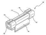
도 1은 활성 물질(12)의 파우더를 수용하는 필리폼 요소(11)를 위한 지지체(10)를 도시하며, 그 위에 차단 수단(13, 13') 및 지지체를 장치의 구성요소에 결합하기 위한 고정 수단(14)이 제공된다.1 shows a
도 1에 도시된 바람직한 실시예에서, 고정 수단(14)의 구조는 예를 들어 버너를 지지하는 금속 요소인 방전 램프를 원통형의 구성요소 위에 설치하기 쉽게 하게 하기 위해 플러그 인 가압 타입이다. 고정 수단을 구성하는 또 하나의 대안적인 방법은 지지체 위에 있는 적합한 금속 요소를 크림핑하는 것에 의한 것이다.In the preferred embodiment shown in FIG. 1, the structure of the fastening means 14 is of a plug-in press type to make it easy to install a discharge lamp, for example a metal element supporting the burner, on a cylindrical component. Another alternative way of constructing the fastening means is by crimping a suitable metal element on the support.
게다가, 필리폼 요소(11)는 그 상부 부분에 슬릿(15)을 갖지만, 앞서 언급되듯이, 본 발명에 따른 지지체는 또한 측면에 슬릿이 제공되지 않은 않는 필리폼 요소에 적용될 수 있다. 또한, 필리폼 요소(11)는, 슬릿이 반드시 지지체의 상부 부분을 향하는 것이 아니라, 그 밖의 어느 곳이라도, 심지어 지지체 바닥을 향하도록 위치될 수 있다.In addition, although the
필리폼 요소의 슬릿의 존재와 위치결정에 관한 이러한 고려사항들은 다음 도면에도 적용된다.These considerations regarding the presence and positioning of the slit of the Philippine element also apply to the following figure.
지지체의 제1 대체 실시예는 필리폼 요소의 중심 부분에 위치된 단일 차단 요소를 포함한다.A first alternative embodiment of the support comprises a single blocking element located in the central portion of the lipid element.
도 2에서, 지지체(20)의 차단 수단은 기능적으로 두 부분을 특징으로 하며, 제1 부분(13)은 필리폼 요소의 측면 표면의 압축에 의해 차단 작용을 가하며, 반면에 차단 부분의 말단 부분(23)은 필리폼 요소의 측면 부분을 향해 만곡된다; 이것은 필리폼 요소 표면 위의 차단 수단에 의해 가해지는 힘의 작용에 의해서뿐만 아니라 기하하적 결속의 작용에 의해서도 필리폼 요소가 지지체 위에 보유되는 것을 한정한다.In FIG. 2, the blocking means of the
도 2에서, 도 1과 공통된 요소는 시적으로 표시되어 있지 않으며, 그리고 추가로 차단 수단(13)의 말단 부분(23)의 만곡부들은 요소(13') 상에도 존재한다(만곡부 23'). 도 2는 차단 수단의 말단 부분의 만곡, 특히 두 개의 측면 플랩의 만곡을 갖는 본 발명에 따른 타입의 지지체를 도시하지만, 단일 플랩에 의해서 또는 더 일반적으로, 차단 수단의 하나 이상의 부분을 만곡시키는 것에 의해서도 동일한 결과가 얻어진다.In FIG. 2, the elements common to FIG. 1 are not marked poetic, and further, the bends of the
또한, 도 2에는 90°의 만곡부가 도시되어 있지만, 구부려진 후에 차단 수단의 단면의 단부에서의 면적이 필리폼 요소의 단면적보다 더 작은 한, 더 낮은 각도의 만곡도 동일한 기능을 제공한다. 이 경우에, 차단 수단은 수은 방출을 방지 또는 제한하고 그리고/또는 흡착 속도를 특별히 참조하여 게터 기능을 제한하는 것인 그 기능을 지키기 위해, 필리폼 단부 면적의 60%를 초과하며 덮지 않는 것이 바람직하다.In addition, although a 90 ° bend is shown in FIG. 2, lower angle curvatures provide the same function as long as the area at the end of the cross section of the blocking means after bending is smaller than the cross-sectional area of the form element. In this case, it is preferred that the blocking means not exceed and cover 60% of the end area of the reformed form to ensure its function of preventing or limiting mercury release and / or limiting the getter function with particular reference to the adsorption rate. Do.
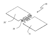
도 3은 본 발명에 따른 필리폼 요소를 위한 지지체의 다른 실시예(30)를 도시한다: 이 경우, 도 2에서 도시된 것과 같은 지지체(20)는 측면 금속 연장부 (31, 31')를 가지며, 측면 금속 연장부는 수은 방출, 게터 물질 활성, 또는 둘 모두를 위한 활성 물질의 활성화 과정 동안의 가열을 위해 일반적으로 사용되는 전자기장의 차단을 개선하는 기능을 갖는다.FIG. 3 shows another embodiment 30 of a support for a lipid element according to the invention: in this case the
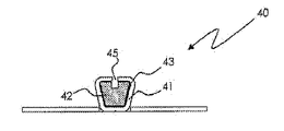
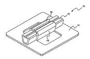
FL에서 사용하는 경우, 금속 측면 연장부는 필리폼 요소의 활성 물질의 활성화 과정을 돕는 것뿐만 아니라 램프에서 전극을 위한 소위 차폐 구조를 형성하는데 유용할 수 있으며, 차폐 구조는 전극 주위에 링처럼 구성되거나 전극 위에 모자처럼 위치되며, 이것은 전형적으로 수 mm 또는 일부 경우에 10mm정도의 거리에 위치된다. 도 4 및 도 4a는 활성 물질(42)의 파우더를 포함하는 필리폼 요소(41)를 위한 지지체(40)를 도시하며, 그 일 단부에 차단 수단(43, 43') 및 지지체를 장치 구성요소에 구속하는 고정 수단(44, 44',44'',...)이 제공된다. 도면은 같은 길이를 가지는 세 개의 고정수단을 도시한다. 그러나, 장치 및 요구되는 고정 타입에 따르면, 당해 업계의 숙련자들이 착안할 수 있는 모든 변형을 기초로 하여 모양과 크기뿐만 아니라 고정 수단의 개수도 변할 수 있다.When used in FL, the metal side extensions can be useful in forming a so-called shielding structure for the electrode in the lamp as well as in assisting in the activation process of the active material of the Philippine element, the shielding structure being constructed like a ring around the electrode or It is positioned like a hat on the electrode, which is typically located at a distance of a few mm or in some cases as much as 10 mm. 4 and 4a show a
차단 수단은 서로에 대하여 상이한 크기를 가지는 것으로 도시된다. 그러나, 본 발명은 차단 수단이 전부 같은 크기를 가지는 특별한 경우도 포함한다.The blocking means are shown to have different sizes with respect to each other. However, the present invention also encompasses the special case in which the blocking means are all the same size.
또한, 필리폼 요소는 상부 부분에 슬릿(45)을 갖지만, 앞서 논의되듯이, 발명의 지지체는 또한 슬라이드 슬릿을 가지지 않는 필리폼 요소에 적용될 수 있거나 또는 대안적으로, 슬릿이 어느 곳도 향할 수 있고, 또한 지지체의 바닥을 향할 수 있다. 필리폼 요소의 슬릿의 존재 및 배열에 관한 이런 고려사항들은 본 발명에 개시된 모든 가능한 실시예들에 적용된다.In addition, the Philippine element has a slit 45 in its upper portion, but as discussed above, the inventive support can also be applied to a Philippine element that does not have a slide slit, or alternatively, the slit can be directed anywhere. And may also face the bottom of the support. These considerations regarding the presence and arrangement of the slit of the Philippine element apply to all possible embodiments disclosed herein.
바람직한 실시예에서, 고정 요소는 탄성적으로 또는 소성 변형에 의해 필리폼 요소를 위한 지지체를 램프를 구성하는 구성요소 중 하나에 구속하며, 고정 요소는 예를 들어 버너를 지지하는 와이어, 또는 고압 방전 램프의 전기적 피드스루(feedthrough) 또는 리드-와이어로 불리는 텅스텐 필라멘트를 지지하는 와이어, 또는 FL 내의 차폐 부재를 지지하기 위한, 제3 전극이라는 명칭으로 알려진 추가적인 와이어 등이다. In a preferred embodiment, the securing element constrains the support for the Philippine element to one of the components constituting the lamp, either elastically or by plastic deformation, the securing element being for example a wire supporting the burner, or a high pressure discharge. Wires supporting tungsten filaments called electrical feedthroughs or lead-wires of lamps, or additional wires known as third electrodes for supporting shielding members in FL.
가능한 대안은 고정 수단을 벽에 부착되는 플래그로서 사용하며 지지체가 최종 장치에 존재하는 관 모양의 부재의 미리 정한 부분의 내부에, 예를 들어 부분적으로 램프의 일단부와 연결되고 업계에 "배출 튜브"로 알려진 배출 파이프 부분에 구속되도록 하는 것이다. 후자의 경우에 발명의 지지체의 목적은, 물리적으로 또는 동일한 고정 핀(fin)들의 신축 효과에 의해, 줄어든 단면을 갖는 상기 튜브의 일부에 대응하게 구속되는 것이다. 일반적으로, 이 목적을 위해 사용될 수 있는 지지체는 예를 들어 크림핑, 용접 또는 가압 플러그인 공정에 적합한 것보다 짧은 길이를 가지는 고정 수단을 특징으로 한다.A possible alternative is to use the fastening means as a flag to be attached to the wall and the support is connected to the inside of the predetermined part of the tubular member present in the final device, for example partly with one end of the lamp, and to the "outtake tube" To be confined to the discharge pipe portion, known as " The object of the inventive support in the latter case is to correspond to a part of the tube having a reduced cross section, either physically or by the stretching effect of the same fixing fins. In general, the support which can be used for this purpose is characterized by fastening means having a shorter length than that suitable for, for example, crimping, welding or pressure plug-in processes.
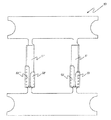
실시예의 하나에서, 예를 들어 도 5에서 도시된 실시예에서, 본 발명은 하나 이상의 필리폼 요소를 차단하는 지지체를 사용하는 것을 제공한다. 이 도면에 구체적으로 도시된 경우에서는 슬릿(55, 55')을 가지는 두 개의 필리폼 요소(51, 51')가 제공되며, 도 4에 도시된 것들과 유사하게, 필리폼 요소들은 차단 수단(53, 53',...)에 의해 차단되고 있다.In one of the embodiments, for example in the embodiment shown in FIG. 5, the present invention provides the use of a support that blocks one or more of the lipid elements. In the case shown specifically in this figure, two
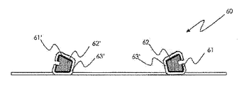
또한, 도 6 및 도 6a는 이 실시예의 가능한 변형예를 도시한다. 슬릿(65, 65')들이 지지체(30)의 양 측면을 향하도록 구성된 필리폼 요소(61, 61')의 동등한 상대 위치결정시에, 차단 수단(63, 63',...)의 모양과 크기는 최종 장치가 요구하는 경우에 필리폼 요소의 슬릿을 차단하지 않도록 최적화될 수 있다. 또한, 도 5 및 도 6에 도시된 실시예의 두 변형예들은 최종 장치 내의 지지체로의 고정을 위해 지지 스트립(64, 64')의 부분을 사용하는 것을 제공한다. 실시예가 단일 필리폼 요소를 지지하는 것을 제공할 때에도 일어날 수 있는 이런 사용은 고정 공정으로서 용접의 사용을 가능하게 하며, 이는 필리폼 요소의 원치않는 과열의 위험을 야기하지 않기 때문이다. 예를 들어, 일부 종류의 램프에 존재하는 차폐물의 표면 위에 직접 지지체를 고정하는데 사용될 수도 있다. 또한, 한 쌍의 필리폼 요소들의 지지체를 특징으로 하는 실시예를 특히 참조하면, 이 지지체는 활성 물질의 활성화 과정을 특히 효과적으로 만드는 부수적인 효과를 가진다.6 and 6a also show possible variations of this embodiment. In the equivalent relative positioning of the
본 발명에 따른 지지체를 구성하는데 유용한 재료는 예를 들어 니켈 도금된 철, 콜드 라미네이티드 강, 스테인리스 강이며; 바람직한 실시예에서 지지체의 재료의 필리폼 요소의 재료와 같다.Materials useful for constructing the support according to the invention are, for example, nickel plated iron, cold laminated steel, stainless steel; In a preferred embodiment it is the same as the material of the Philippine element of the material of the support.
삽입될 필리폼 요소가 오직 하나일 때면 언제든(도 5 및 도 6의 실시예에서와 같이 적어도 두 개가 아님), RF 소스에 의한 활성화 과정의 효율을 최대할 수 있는 본 발명에 따른 또 하나의 대안적인 실시예가 도 7에서 도시된다. 지지체(70)는 두 개의 차단 수단(73, 73')에 의해 지지체에 고정되는 필리폼 요소(71)와 대응하여 유도 가열 흐름을 개선시킬 수 있는 천공된 측면 금속 연장부(72)에 의해 개선되었다. 측면 금속 연장부는 오직 선택적으로만 (예를 들어 용접에 의해)장치에 대한 고정 수단으로 작용할 수 있다. 실제로, 기계적 고정 요소가 존재하더라도 유사한 실시예들이 적용될 수 있다. 발명을 수행하는데 관여하는 게터 물질들 중에서는, 모두 본 출원인 명의의, 미국 특허 제US3,203,901호(지르코늄-알루미늄 합금), 미국 특허 제US4,306,887호(지르코늄-철 합금), 및 미국 특허 제US5,961,750호(지르코늄-코발트-희토류)에 설명된 것들이 있다. 웨스팅하우스 일레트릭 코포레이션의 특허 제GB1,248,184호 또는 본 출원인 명의의 국제 특허 출원 공개 제WO03/029502호 및 제WO2007/099575호에서 설명된 바와 같이, 특히 높은 온도에서의 수소 흡착을 위해 이트륨 또는 이것의 합금을 사용하는 것이 알려져 있다.Another alternative according to the invention which can maximize the efficiency of the activation process by the RF source at any time (but not at least two as in the embodiment of FIGS. 5 and 6) when there is only one Philippine element to be inserted An exemplary embodiment is shown in FIG. The
활성 물질이 수은 방출을 위한 파우더를 포함하는 경우에, 이들은 바람직하게는 미국 특허 제US3657589호에 설명된 화합물 즉, TixZyHgz 로 구성되며, 여기서, x와 y는 이들의 합이 3 내지 13 사이라는 조건으로 0부터 13까지 변하고, z는 1 또는 2이다. 특히, Ti3Hg의 사용이 바람직하다. 이 화합물들은 수은 방출을 최대화하는 프로모터와 결합하여 사용될 수도 있다. 상기 프로모터는 유럽 특허 제EP 0669639호에서 설명된 바와 같이 구리와 주석, 인듐, 은 중에서 선택된 적어도 하나의 제2 요소로 형성되거나, 유럽 특허 제EP0691670호에서 설명된 바와 같이 구리와 실리콘으로 형성되거나, 유럽 특허 제EP0737995호에 설명된 바와 같이 구리, 주석 및 희토류로 형성된다.If the active substance comprises a powder for mercury release, they preferably consist of the compound described in US Pat. No. US3657589, ie Ti x Z y Hg z , where x and y are the sum of these 3 And from 13 to 13, and z is 1 or 2. In particular, the use of Ti 3 Hg is preferred. These compounds may be used in conjunction with a promoter that maximizes mercury release. The promoter is formed of at least one second element selected from copper, tin, indium, silver, as described in EP 0669639, or formed of copper and silicon, as described in EP EP 0691670, It is formed of copper, tin and rare earths, as described in European Patent No. EP0737995.
대안적으로, 수은 방출 화합물은 국제 공개 제WO2006/008771호에 설명된 바와 같이 10중량% 내지 중량 42중량% 범위의 티타늄, 14중량% 내지 50중량% 범위의 구리, 20중량% 내지 50중량% 범위의 수은 및 1중량% 내지 20중량%인 주석, 크롬 및 실리콘 중의 하나 이상의 원소를 포함하거나, 영국 특허 제GB2056490호에 설명된 바와 같이 티타늄-구리-수은의 3원 화합물을 포함하는 수은-방출 화합물이 사용될 수 있다.Alternatively, the mercury releasing compound may comprise titanium in the range of 10% to 42% by weight, copper in the range of 14% to 50% by weight, 20% to 50% by weight, as described in WO2006 / 008771. Mercury-emitting comprising mercury in the range and 1 to 20% by weight of at least one element of tin, chromium and silicon, or comprising ternary compounds of titanium-copper-mercury as described in GB 2056490. Compounds can be used.
활성 물질은 유리하게는 수은 화합물에 추가하여, 예를 들어 미국 특허 제 US3203901호에서 설명된 16%의 알루미늄을 포함하는 지르코늄-알루미늄 합금, 또는, 80중량%의 지르코늄, 15중량%의 코발트 그리고 나머지 MM을 포함하는 지르코늄-코발트-MM (여기서, MM은 이트륨, 란타늄, 세륨, 프라세오디뮴, 네오디뮴, 희토류 금속 또는 원소들의 화합물을 나타냄)과 같은 게터 물질을 포함할 수도 있다. 이 경우 수은 방출 화합물과 게터 물질은 둘 모두 혼합된 파우더의 형태로 필리폼 요소 안에 존재하고, 대체로 125㎛보다 작은 입자크기를 갖는다.The active material is advantageously in addition to the mercury compound, for example, a zirconium-aluminum alloy comprising 16% aluminum, as described in US Pat. No. US3203901, or 80% zirconium, 15% by weight cobalt and the rest. Zirconium-cobalt-MM including MM, where MM represents yttrium, lanthanum, cerium, praseodymium, neodymium, rare earth metals or compounds of elements. In this case both the mercury releasing compound and the getter material are present in the Philippine element in the form of a mixed powder and generally have a particle size of less than 125 μm.
전형적으로, 수은 방출 화합물의 파우더와 게터 물질의 파우더 사이의 중량비는 8:2 와 9:1 사이로 구성된다.Typically, the weight ratio between the powder of the mercury releasing compound and the powder of the getter material is comprised between 8: 2 and 9: 1.
결국, 활성 물질이 오직 게터 물질일 때, 활성 물질은 예를 들어 바륨-알루미늄 또는 바륨-알루미늄 합금과 니켈의 조합물과 같은 증발성 타입 또는 예를 들어 이트륨 및 그것의 이원 합금, 지르코늄-알루미늄, 지르코늄-코발트-MM, 지르코늄-철-이트륨 합금 또는 더 일반적으로 지르코늄-M-이트륨 합금과 같은 비증발성 타입일 수 있다.After all, when the active material is only a getter material, the active material is of evaporative type, for example barium-aluminum or a combination of barium-aluminum alloys and nickel or for example yttrium and its binary alloys, zirconium-aluminum, It may be a non-evaporable type such as zirconium-cobalt-MM, zirconium-iron-yttrium alloy or more generally zirconium-M-yttrium alloy.
본 발명에 따른 활성 물질을 포함하는 필리폼 요소를 위한 지지체의 제조 방법에 관해서, 바람직하게는 금속 스트립으로 형성된 개시 물질(바람직하게는, 강 또는 니켈 도금된 철)의 사용이 수반되며, 개시 물질은 기계적인 또는 미학적인 특징 또는 부식 현상에 대한 저항 특징을 개선하는 목적을 가진 가능한 금속 또는 중합체 코팅을 가질 수 있다. 스트립은 두 개의 연속적이고 자동화된 단계에 의해 형성되며, 이들은 각각 스탬핑과 벤딩이다. 가능한 마지막 리베팅 단계는 활성 물질을 포함하는 필리폼 요소의 상기 지지 요소를 고정하는 것을 허용한다.Regarding the process for the preparation of the support for the Philippine element comprising the active material according to the invention, it is preferably accompanied by the use of a starting material (preferably steel or nickel plated iron) formed from a metal strip, starting material Silver may have a possible metal or polymer coating with the aim of improving mechanical or aesthetic features or resistance to corrosion phenomena. The strip is formed by two successive, automated steps, each of which is stamping and bending. The last possible riveting step allows for fixing the support element of the lipid element comprising the active material.
제 2 태양에서, 본 발명은 파우더 형태의 활성 물질을 수용하고 있는 필리폼 요소를 위한 지지체를 포함하는 램프에 관한 것이며, 이것은 상기 지지체 위의 필리폼 요소의 차단 수단, 상기 지지체를 위한 고정 수단을 포함하며, 상기 차단 수단은 필리폼 요소 위에 25MPa 내지 90MPa의 압력을 가하는 것을 특징으로 한다.In a second aspect, the present invention relates to a lamp comprising a support for a Philippine element containing an active material in powder form, which comprises a means for blocking the Philippine element on the support, a fixing means for the support. And the blocking means is adapted to apply a pressure of 25 MPa to 90 MPa on the form element.
도 8에는, 본 발명에 따른 지지체를 수용할 수 있는 램프의 단면도가 도시된다. 특히, 단면도는 포괄적인 고압 방전 램프(80)를 대표하며, 전기 커넥터가 램프의 한 측면에만 있는 타입으로, 일반적으로 유리 또는 석영인 벌브(81)로 형성되며, 그 안에 반투명한 알루미나 또는 석영으로 만들어진 대체로 구형 또는 원통형의 용기로 형성된 소위 버너(82)가 제공된다. 버너의 두 개의 단부에 두 개의 전극(83, 83')이 제공되며, 그 안에 필러 가스와 증기형태이거나 램프가 켜짐으로써 증기화 될 수 있는 하나 이상의 금속 또는 화합물(방전이 발생하는 매체임)이 제공되며; 석영으로 만들어질 때, 버너의 두 단부(84, 84')는 고온 압력에 의해 폐쇄된다. 버너는 두 개의 금속 지지 부품(85, 86)에 의해 제 위치에 유지되며, 지지 부품들은 전기적으로 전극들을 접속하는 기능을 가지며, 그 중 하나는 일반적으로 버너 구조체와 평행하게 위치된 부분을 갖는다.In figure 8 a cross-sectional view of a lamp capable of receiving a support according to the invention is shown. In particular, the cross-sectional view represents a comprehensive high-
도 8에서 도시된 실시예에서, 지지체(86) 상에는 램프 발광의 최소한의 가능한 디밍을 유발하기 위해 본 발명에 따라서 만들어지고 요소(86)에 평행하게 요소(86)와 벌브(81) 사이에 위치된 필리폼 요소를 위한 지지체(20)가 위치된다.In the embodiment shown in FIG. 8, on the
램프의 구조체는 외부 접점(88, 88'), 금속 피드스루(87, 87') 및 벌브(89)의 하나의 폐쇄부에 의해 더 완성된다.The structure of the lamp is further completed by one closure of the
바람직한 실시예에서, 고정 수단은 기계적인 변형에 의해 또는 탄성적으로 필리폼 요소를 위한 지지체를, 예를 들어, 버너의 지지 나사(도 8에서 도시되듯이) 또는 고압 방전 램프 내의 전기적 피드스루 또는 리드 와이어라 불리는 텅스텐 필라멘트의 지지 와이어, 또는 FL 내에 스크리닝 요소를 지지하기 위한 제3 전극으로 알려진 추가적인 와이어 같은 램프의 구조 요소 중 하나에 구속함으로써 고정된다.In a preferred embodiment, the fastening means is provided by means of mechanical deformation or elastically by means of a support for the form element, for example by a support screw of the burner (as shown in figure 8) or by an electrical feedthrough in a high-pressure discharge lamp or It is secured by restraining either one of the tungsten filament's supporting wires, called lead wires, or a structural element of the lamp, such as an additional wire known as a third electrode for supporting the screening element in the FL.
FL 램프의 경우에, 활성 물질은 수은 방출 화합물의 파우더 및 선택적으로 게터 물질 파우더를 포함하며, 고 휘도 방전 램프의 경우에, 활성 물질은 게터 물질 파우더를 포함한다.In the case of FL lamps, the active material comprises a powder of mercury emitting compound and optionally a getter material powder, and in the case of a high brightness discharge lamp, the active material comprises a getter material powder.
특정 실시예에서, 램프는 측면 연장부가 제공된 필리폼 요소를 위한 지지체를 포함하며, 이 지지체는 램프의 리드 와이어들 중 하나에 또는 고정 수단에 의해 소위 제3 전극에 고정된다. 가능하다면, 적절한 길이를 가지는 측면 연장부는 전극 주위에 폐쇄된 또는 절반만 폐쇄된 링의 형태인 차폐부를 갖도록 만곡되고 형상이 결정되거나, 상술한 바와 같이 전극 위로 적절한 거리에 위치될 수 있다.In a particular embodiment, the lamp comprises a support for a Philippine element provided with a lateral extension, which is fixed to one of the lead wires of the lamp or to the so-called third electrode by a fixing means. If possible, the lateral extension having an appropriate length may be curved and shaped to have a shield in the form of a closed or half closed ring around the electrode, or positioned at an appropriate distance over the electrode as described above.
본 발명은 다음의 예시들에 의해 추가적으로 설명될 것이다. 이런 제한없는 예시는 통상의 기술자가 어떻게 발명을 실시하는지를 교시하고 발명을 실행하기 위한 최선의 형태를 기술하기 위한 의도의 일부 실시예를 설명한다.The invention will be further illustrated by the following examples. This non-limiting example describes some embodiments of the intention to teach the skilled person how to practice the invention and to describe the best mode for carrying out the invention.
예 1Example 1
약 42MPa의 압축 작용으로 필리폼 요소(길이 약 5mm, 약 1mm의 최대 횡단 폭 및 약 0.8mm 높이를 가지는 사다리꼴 단면)를 도 4에서 도시된 본 발명에 따른 지지체에 고정함으로써 활성 물질 수용 시스템이 얻어진다. 진공상태(10 - 4 mbar보다 낮은 압력)에서, 시스템은 40mm의 직경을 가진 유도 코일에 의해 20 내지 30초 동안 가열되었고, 코일은 2KW의 정격 출력을 가진 RF 전력 공급원에 접속되었다. 테스트 동안, 시스템은 직각으로 전기 자기장에 커플링된다. 표 1에는, 압축 작용의 영향인 필리폼 요소의 단면의 변형 및 RF 유도에 의해 얻어진 유효 온도가 기록되어 있다.The compression action of about 42 MPa results in the active material receiving system being obtained by securing the Philippine element (a trapezoidal cross section having a length of about 5 mm, a maximum transverse width of about 1 mm and a height of about 0.8 mm) to the support according to the invention shown in FIG. Lose. Vacuum-in (10 a pressure of less than 4 mbar), the system was heated for 20 to 30 seconds by an induction coil with a diameter of 40mm, the coil was connected to an RF power source with a rated power of 2KW. During the test, the system is coupled to the electric magnetic field at right angles. In Table 1, the effective temperature obtained by the deformation | transformation of the cross-section of a Filipino element and RF induction which are the influence of a compression action is recorded.
예 2(비교)Example 2 (comparison)
활성 물질 수용 시스템은 예 1에서와 같이 필리폼 분배 요소를 고정함으로써 그러나 약 18MPa의 압력 작용을 사용하여 얻어졌다. 표 1에는, 압축 작용의 영향인 필리폼 요소의 단면의 변형 및 RF에 의해 얻어진 유효 온도가 기록되어 있다.The active substance receiving system was obtained by fixing the lipid distribution element as in Example 1 but using a pressure action of about 18 MPa. In Table 1, the deformation | transformation of the cross section of the lipform element which is an influence of a compression action, and the effective temperature obtained by RF are recorded.
(MPa)Compression
(MPa)
(%)transform
(%)
(초)time
(second)
(℃)(° C)
One
2
예에 의해 나타난 바와 같이, 본 발명에 따라 얻어진 지지체는 필리폼 요소의 효과적인 차단을 보장할 수 있을 뿐만 아니라 활성화 과정 동안 개선된 가열을 보장할 수 있다: 예 1에 설명된 본 발명에 따른 샘플은 사실상 몇몇 장치의 제조 생산 라인에서 요구되듯이, 30초 후에 (가장 대중적인 활성 물질에 의해 요구되는바와 같이) 500℃를 초과하여 가열된다. 비교 예는 필리폼 요소가 지지체 상에서 차단되더라도 활성화 단계의 요구 효율에 부합하지 못하는데, 온도가 요구된 것보다 낮게 관찰되기 때문이다.
As can be seen by the examples, the support obtained according to the present invention can not only ensure effective blocking of the lipid element, but also ensure improved heating during the activation process: The sample according to the invention described in Example 1 In fact, as required in the manufacturing production line of some devices, after 30 seconds they are heated above 500 ° C. (as required by the most popular active materials). The comparative example does not meet the required efficiency of the activation step even if the lipform element is blocked on the support, since the temperature is observed lower than required.
Claims (19)
상기 차단 수단은 필리폼 요소에 25MPa 내지 90MPa의 압력을 가하는 것을 특징으로 하는
지지체.A support (10; 20; 30; 40; 50; 60; 70) for at least one Philippi element (11; 41; 51; 61; 71) containing an active substance in the form of a powder (12), said A support comprising blocking means 13, 13 ′; 23, 23 ′;. To
The blocking means is characterized in that to apply a pressure of 25MPa to 90MPa to the Philippine element
Support.
지지체.The method of claim 1, wherein the pressure is 25MPa to 55MPa
Support.
지지체.The method of claim 1, wherein the cross-sectional area of the Philippine corresponding to the blocking means is reduced by less than 8% with respect to the cross-sectional area of the Philippine element not corresponding to the blocking means.
Support.
지지체.4. The method of claim 3, wherein the reduction in cross-sectional area is between 1.5% and 4% of the cross-sectional area of the lipid element that does not correspond to the blocking means.
Support.
지지체.The method of claim 1 wherein said securing means is maintained by crimping or by only elastic force.
Support.
지지체.The method of claim 1, wherein said blocking means is at the end of the Filipino element and has a curved end section.
Support.
지지체.7. The curved end section of claim 6 wherein the curved end section does not cover more than 60% of the area of the end of the Filipino element.
Support.
지지체.A side extension (31, 31 ') is provided according to claim 1,
Support.
지지체.The material of claim 1 wherein the material of the support is nickel plated iron or steel.
Support.
지지체.The method of claim 1, wherein the element is a slit (15; 45) is provided on the side surface
Support.
지지체.The method of claim 1, wherein the lipid element contains a powder of one or more getter materials.
Support.
지지체.The method of claim 1, wherein the lipid element contains a powder of one or more compounds for mercury release.
Support.
지지체.13. The method of claim 12, wherein the lipid element also contains a powder of one or more getter materials.
Support.
램프.A support for a lipid element containing a powder of the active material according to claim 1
lamp.
램프.15. The lamp of claim 14 wherein the lamp is a low pressure mercury lamp.
lamp.
램프.The method of claim 14, wherein the active substance comprises a powder of one or more compounds for mercury release.
lamp.
램프.The method of claim 16, wherein the active material comprises a powder of one or more getter materials
lamp.
램프.15. The lamp of claim 14 wherein the lamp comprises a burner
lamp.
램프.19. The method of claim 18, wherein the active material comprises a powder of one or more getter materials
lamp.
Applications Claiming Priority (4)
| Application Number | Priority Date | Filing Date | Title |
|---|---|---|---|
| ITMI2009A001255 | 2009-07-15 | ||
| IT001255A ITMI20091255A1 (en) | 2009-07-15 | 2009-07-15 | SUPPORT FOR ELEMENTS FILIFORMS CONTAINING AN ACTIVE MATERIAL |
| ITMI20100085 ITMI20100085U1 (en) | 2010-03-24 | 2010-03-24 | SUPPORT FOR ELEMENTS FILIFORMS CONTAINING AN ACTIVE MATERIAL |
| ITMI2010U000085 | 2010-03-24 |
Publications (1)
| Publication Number | Publication Date |
|---|---|
| KR20120052317A true KR20120052317A (en) | 2012-05-23 |
Family
ID=43448966
Family Applications (1)
| Application Number | Title | Priority Date | Filing Date |
|---|---|---|---|
| KR1020127003874A KR20120052317A (en) | 2009-07-15 | 2010-07-07 | Support for filiform elements containing an active material |
Country Status (8)
| Country | Link |
|---|---|
| US (1) | US8427051B2 (en) |
| EP (1) | EP2319066B1 (en) |
| JP (1) | JP5560330B2 (en) |
| KR (1) | KR20120052317A (en) |
| CN (1) | CN102473566B (en) |
| AT (1) | ATE539443T1 (en) |
| TW (1) | TW201133545A (en) |
| WO (1) | WO2011006811A1 (en) |
Families Citing this family (5)
| Publication number | Priority date | Publication date | Assignee | Title |
|---|---|---|---|---|
| ITMI20120940A1 (en) * | 2012-05-31 | 2013-12-01 | Getters Spa | PERFECT COMPOSITIONS FOR MERCURY DOSAGE |
| ITMI20131171A1 (en) * | 2013-07-11 | 2015-01-11 | Getters Spa | IMPROVED DISPENSER OF METAL VAPORS |
| ITMI20131658A1 (en) * | 2013-10-08 | 2015-04-09 | Getters Spa | COMBINATION OF MATERIALS FOR MERCURY RELEASE DEVICES AND DEVICES CONTAINING THIS MATERIAL COMBINATION |
| JP6368053B2 (en) | 2015-02-26 | 2018-08-01 | フィリップス ライティング ホールディング ビー ヴィ | Lighting device having a dispenser of reactive substances |
| CN107400854B (en) * | 2017-07-17 | 2019-01-22 | 云南师范大学 | Non-evaporation type low temp activation Zr base Fe Getter Films Prepared and preparation method thereof |
Family Cites Families (28)
| Publication number | Priority date | Publication date | Assignee | Title |
|---|---|---|---|---|
| US1733809A (en) * | 1928-06-26 | 1929-10-29 | Westinghouse Lamp Co | Means for gettering electrical discharge devices |
| US2928925A (en) * | 1956-08-15 | 1960-03-15 | Rca Corp | Getter structure |
| US3203901A (en) * | 1962-02-15 | 1965-08-31 | Porta Paolo Della | Method of manufacturing zirconiumaluminum alloy getters |
| GB1248184A (en) | 1969-04-03 | 1971-09-29 | Westinghouse Electric Corp | Yttrium alloy getter |
| US3657589A (en) * | 1969-10-20 | 1972-04-18 | Getters Spa | Mercury generation |
| GB1575890A (en) * | 1978-03-31 | 1980-10-01 | Thorn Electrical Ind Ltd | Heating of dosing capsule |
| IT1115156B (en) * | 1979-04-06 | 1986-02-03 | Getters Spa | ZR-FE ALLOYS FOR HYDROGEN ABSORPTION AT LOW TEMPERATURES |
| IT1193796B (en) | 1979-07-19 | 1988-08-24 | Getters Spa | COMPOSITION AND DEVICE FOR THE EMISSION OF MERCURY AND ELECTRONIC TUBES INCLUDING SUCH DEVICE |
| JPH03285232A (en) | 1990-03-30 | 1991-12-16 | Sanyo Electric Co Ltd | Wire getter support structure |
| JP3285232B2 (en) | 1992-09-25 | 2002-05-27 | 松下電工株式会社 | Switch with indicator light |
| JPH06111775A (en) * | 1992-09-30 | 1994-04-22 | Toshiba Lighting & Technol Corp | Low pressure discharge lamp |
| IT1273338B (en) | 1994-02-24 | 1997-07-08 | Getters Spa | COMBINATION OF MATERIALS FOR MERCURY DISPENSING DEVICES PREPARATION METHOD AND DEVICES SO OBTAINED |
| IT1270598B (en) | 1994-07-07 | 1997-05-07 | Getters Spa | COMBINATION OF MATERIALS FOR MERCURY DISPENSING DEVICES PREPARATION METHOD AND DEVICES SO OBTAINED |
| IT1273531B (en) | 1995-04-10 | 1997-07-08 | Getters Spa | COMBINATIONS OF MATERIALS FOR INTEGRATED DEVICES GETTERS AND MERCURY DISPENSERS AND DEVICES SO OBTAINED |
| IT1290451B1 (en) | 1997-04-03 | 1998-12-03 | Getters Spa | NON-EVAPORABLE GETTER ALLOYS |
| IT1291974B1 (en) | 1997-05-22 | 1999-01-25 | Getters Spa | DEVICE AND METHOD FOR THE INTRODUCTION OF SMALL QUANTITIES OF MERCURY IN FLUORESCENT LAMPS |
| US6452322B1 (en) * | 1998-11-27 | 2002-09-17 | Sony Corporation | Cathode-ray tube and its getter supporter |
| JP2000317247A (en) * | 1999-05-14 | 2000-11-21 | Sumitomo Metal Ind Ltd | Gas absorption getter and its production |
| US6456004B1 (en) * | 1999-09-10 | 2002-09-24 | General Electric Company | Fluorescent lamp having uniquely configured container containing amalgam for regulating mercury vapor equilibrium |
| IT1317117B1 (en) | 2000-03-06 | 2003-05-27 | Getters Spa | METHOD FOR THE PREPARATION OF MERCURY DISPENSING DEVICES FOR USE IN FLUORESCENT LAMPS |
| ITMI20012033A1 (en) | 2001-09-28 | 2003-03-28 | Getters Spa | GETTER ALLOYS FOR HYDROGEN ABSORPTION AT HIGH TEMPERSTURES |
| ITMI20041494A1 (en) | 2004-07-23 | 2004-10-23 | Getters Spa | COMPOSITIONS FOR THE RELEASE OF MERCURY AND PROCESS FOR THEIR PRODUCTION |
| ITMI20050281A1 (en) * | 2005-02-23 | 2006-08-24 | Getters Spa | MINIATURIZED HIGH PRESSURE DISCHARGE LAMP CONTAINING A GETTER DEVICE |
| ITMI20060361A1 (en) | 2006-02-28 | 2007-09-01 | Getters Spa | HYDROGEN ABSORPTION THROUGH THE USE OF NON EVAPORABLE GETTER ALLOYS METHOD AND APPLICATIONS |
| GB0605960D0 (en) | 2006-03-24 | 2006-05-03 | Galley Geoffrey H | Expandable spinal prosthesis |
| CN201048119Y (en) * | 2007-06-15 | 2008-04-16 | 南京泰欧科技开发有限公司 | Minitype mercury-releasing suction gas element |
| DE102007033879A1 (en) * | 2007-07-20 | 2009-01-22 | Osram Gesellschaft mit beschränkter Haftung | Carrier element, on which a Hg-containing material is designed for attachment in a discharge lamp, and discharge lamp with such a support element |
| ITRM20080334A1 (en) | 2008-06-25 | 2009-12-26 | Getters Spa | FLUORESCENT LAMP WITH HOT CATODO CONTAINING A DEVICE FOR RELEASING MERCURY AND GETTER |
-
2010
- 2010-07-07 WO PCT/EP2010/059706 patent/WO2011006811A1/en active Application Filing
- 2010-07-07 CN CN201080029342.6A patent/CN102473566B/en not_active Expired - Fee Related
- 2010-07-07 AT AT10732691T patent/ATE539443T1/en active
- 2010-07-07 KR KR1020127003874A patent/KR20120052317A/en not_active Application Discontinuation
- 2010-07-07 US US12/936,388 patent/US8427051B2/en active Active
- 2010-07-07 EP EP10732691A patent/EP2319066B1/en not_active Not-in-force
- 2010-07-07 JP JP2012519977A patent/JP5560330B2/en not_active Expired - Fee Related
- 2010-07-09 TW TW099122665A patent/TW201133545A/en unknown
Also Published As
| Publication number | Publication date |
|---|---|
| TW201133545A (en) | 2011-10-01 |
| WO2011006811A1 (en) | 2011-01-20 |
| US8427051B2 (en) | 2013-04-23 |
| EP2319066A1 (en) | 2011-05-11 |
| CN102473566A (en) | 2012-05-23 |
| JP5560330B2 (en) | 2014-07-23 |
| CN102473566B (en) | 2015-08-05 |
| EP2319066B1 (en) | 2011-12-28 |
| JP2012533160A (en) | 2012-12-20 |
| US20110204774A1 (en) | 2011-08-25 |
| ATE539443T1 (en) | 2012-01-15 |
Similar Documents
| Publication | Publication Date | Title |
|---|---|---|
| JP5174148B2 (en) | Low pressure mercury discharge lamp with amalgam capsule with amalgam chamber | |
| KR20120052317A (en) | Support for filiform elements containing an active material | |
| RU2340033C1 (en) | High pressure gas-dicharge tube that contains gas absorbing device | |
| US3549937A (en) | Low pressure mercury vapour discharge lamp including an alloy type getter coating | |
| US3504215A (en) | Planar fluorescent lamp with integral amalgam type mercury-vapor pressure control component | |
| US8314553B2 (en) | Discharge lamp | |
| US6707246B1 (en) | Low-pressure mercury vapor discharge lamp with improved auxiliary amalgam | |
| WO2009156334A1 (en) | Hot cathode fluorescent lamp containing a device for mercury release and a getter | |
| US3069581A (en) | Low pressure discharge lamp | |
| JP5449391B2 (en) | Mercury supply system for fluorescent lamps | |
| KR970005770B1 (en) | A low pressure mercury vapour discharge lamp | |
| US20050200257A1 (en) | Fluorescent lamp with reduced end blackening and mount therefor | |
| JP2002515636A (en) | Low pressure mercury vapor discharge lamp | |
| JP2004525494A (en) | Low pressure mercury vapor discharge lamp | |
| US3549936A (en) | Low pressure mercury vapor discharge lamps including an alloy type getter coating | |
| US20060097617A1 (en) | Cathode unit for fluorescent lamps | |
| JP4861680B2 (en) | Fluorescent lamp | |
| EP2395540A1 (en) | Positioning of auxiliary amalgam in compact fluorescent lamp | |
| JP3405672B2 (en) | Light bulb type fluorescent lamp | |
| JP4221654B2 (en) | Light bulb-type fluorescent lamp and lighting device | |
| EP0555619A1 (en) | Cathode screen for gas discharge lamps | |
| JP2733342B2 (en) | Electrodeless discharge lamp | |
| US20020158566A1 (en) | Low-pressure mercury vapor discharge lamp | |
| AU2015271874A1 (en) | Ceramic metal halide lamp | |
| JP2010232024A (en) | Luminous tube for fluorescent lamp, and method of manufacturing the same and fluorescent lamp with built-in stabilizer using the same |
Legal Events
| Date | Code | Title | Description |
|---|---|---|---|
| WITN | Application deemed withdrawn, e.g. because no request for examination was filed or no examination fee was paid |