KR20120042693A - Direct marking printing system and substrate media registration system in printing system - Google Patents
Direct marking printing system and substrate media registration system in printing system Download PDFInfo
- Publication number
- KR20120042693A KR20120042693A KR1020110108683A KR20110108683A KR20120042693A KR 20120042693 A KR20120042693 A KR 20120042693A KR 1020110108683 A KR1020110108683 A KR 1020110108683A KR 20110108683 A KR20110108683 A KR 20110108683A KR 20120042693 A KR20120042693 A KR 20120042693A
- Authority
- KR
- South Korea
- Prior art keywords
- substrate medium
- tilt correction
- substrate
- medium
- tilt
- Prior art date
Links
Images


Classifications
-
- B—PERFORMING OPERATIONS; TRANSPORTING
- B41—PRINTING; LINING MACHINES; TYPEWRITERS; STAMPS
- B41J—TYPEWRITERS; SELECTIVE PRINTING MECHANISMS, i.e. MECHANISMS PRINTING OTHERWISE THAN FROM A FORME; CORRECTION OF TYPOGRAPHICAL ERRORS
- B41J11/00—Devices or arrangements of selective printing mechanisms, e.g. ink-jet printers or thermal printers, for supporting or handling copy material in sheet or web form
- B41J11/0095—Detecting means for copy material, e.g. for detecting or sensing presence of copy material or its leading or trailing end
-
- B—PERFORMING OPERATIONS; TRANSPORTING
- B41—PRINTING; LINING MACHINES; TYPEWRITERS; STAMPS
- B41J—TYPEWRITERS; SELECTIVE PRINTING MECHANISMS, i.e. MECHANISMS PRINTING OTHERWISE THAN FROM A FORME; CORRECTION OF TYPOGRAPHICAL ERRORS
- B41J2/00—Typewriters or selective printing mechanisms characterised by the printing or marking process for which they are designed
- B41J2/005—Typewriters or selective printing mechanisms characterised by the printing or marking process for which they are designed characterised by bringing liquid or particles selectively into contact with a printing material
- B41J2/01—Ink jet
-
- B—PERFORMING OPERATIONS; TRANSPORTING
- B41—PRINTING; LINING MACHINES; TYPEWRITERS; STAMPS
- B41J—TYPEWRITERS; SELECTIVE PRINTING MECHANISMS, i.e. MECHANISMS PRINTING OTHERWISE THAN FROM A FORME; CORRECTION OF TYPOGRAPHICAL ERRORS
- B41J13/00—Devices or arrangements of selective printing mechanisms, e.g. ink-jet printers or thermal printers, specially adapted for supporting or handling copy material in short lengths, e.g. sheets
- B41J13/26—Registering devices
-
- B—PERFORMING OPERATIONS; TRANSPORTING
- B41—PRINTING; LINING MACHINES; TYPEWRITERS; STAMPS
- B41J—TYPEWRITERS; SELECTIVE PRINTING MECHANISMS, i.e. MECHANISMS PRINTING OTHERWISE THAN FROM A FORME; CORRECTION OF TYPOGRAPHICAL ERRORS
- B41J2/00—Typewriters or selective printing mechanisms characterised by the printing or marking process for which they are designed
- B41J2/005—Typewriters or selective printing mechanisms characterised by the printing or marking process for which they are designed characterised by bringing liquid or particles selectively into contact with a printing material
- B41J2/01—Ink jet
- B41J2/015—Ink jet characterised by the jet generation process
- B41J2/04—Ink jet characterised by the jet generation process generating single droplets or particles on demand
- B41J2/045—Ink jet characterised by the jet generation process generating single droplets or particles on demand by pressure, e.g. electromechanical transducers
- B41J2/04501—Control methods or devices therefor, e.g. driver circuits, control circuits
- B41J2/04505—Control methods or devices therefor, e.g. driver circuits, control circuits aiming at correcting alignment
-
- B—PERFORMING OPERATIONS; TRANSPORTING
- B41—PRINTING; LINING MACHINES; TYPEWRITERS; STAMPS
- B41J—TYPEWRITERS; SELECTIVE PRINTING MECHANISMS, i.e. MECHANISMS PRINTING OTHERWISE THAN FROM A FORME; CORRECTION OF TYPOGRAPHICAL ERRORS
- B41J25/00—Actions or mechanisms not otherwise provided for
- B41J25/001—Mechanisms for bodily moving print heads or carriages parallel to the paper surface
-
- B—PERFORMING OPERATIONS; TRANSPORTING
- B41—PRINTING; LINING MACHINES; TYPEWRITERS; STAMPS
- B41J—TYPEWRITERS; SELECTIVE PRINTING MECHANISMS, i.e. MECHANISMS PRINTING OTHERWISE THAN FROM A FORME; CORRECTION OF TYPOGRAPHICAL ERRORS
- B41J29/00—Details of, or accessories for, typewriters or selective printing mechanisms not otherwise provided for
- B41J29/38—Drives, motors, controls or automatic cut-off devices for the entire printing mechanism
- B41J29/393—Devices for controlling or analysing the entire machine ; Controlling or analysing mechanical parameters involving printing of test patterns
-
- B—PERFORMING OPERATIONS; TRANSPORTING
- B65—CONVEYING; PACKING; STORING; HANDLING THIN OR FILAMENTARY MATERIAL
- B65H—HANDLING THIN OR FILAMENTARY MATERIAL, e.g. SHEETS, WEBS, CABLES
- B65H7/00—Controlling article feeding, separating, pile-advancing, or associated apparatus, to take account of incorrect feeding, absence of articles, or presence of faulty articles
- B65H7/02—Controlling article feeding, separating, pile-advancing, or associated apparatus, to take account of incorrect feeding, absence of articles, or presence of faulty articles by feelers or detectors
- B65H7/06—Controlling article feeding, separating, pile-advancing, or associated apparatus, to take account of incorrect feeding, absence of articles, or presence of faulty articles by feelers or detectors responsive to presence of faulty articles or incorrect separation or feed
- B65H7/08—Controlling article feeding, separating, pile-advancing, or associated apparatus, to take account of incorrect feeding, absence of articles, or presence of faulty articles by feelers or detectors responsive to presence of faulty articles or incorrect separation or feed responsive to incorrect front register
-
- B—PERFORMING OPERATIONS; TRANSPORTING
- B65—CONVEYING; PACKING; STORING; HANDLING THIN OR FILAMENTARY MATERIAL
- B65H—HANDLING THIN OR FILAMENTARY MATERIAL, e.g. SHEETS, WEBS, CABLES
- B65H7/00—Controlling article feeding, separating, pile-advancing, or associated apparatus, to take account of incorrect feeding, absence of articles, or presence of faulty articles
- B65H7/20—Controlling associated apparatus
-
- B—PERFORMING OPERATIONS; TRANSPORTING
- B65—CONVEYING; PACKING; STORING; HANDLING THIN OR FILAMENTARY MATERIAL
- B65H—HANDLING THIN OR FILAMENTARY MATERIAL, e.g. SHEETS, WEBS, CABLES
- B65H9/00—Registering, e.g. orientating, articles; Devices therefor
- B65H9/002—Registering, e.g. orientating, articles; Devices therefor changing orientation of sheet by only controlling movement of the forwarding means, i.e. without the use of stop or register wall
-
- B—PERFORMING OPERATIONS; TRANSPORTING
- B41—PRINTING; LINING MACHINES; TYPEWRITERS; STAMPS
- B41J—TYPEWRITERS; SELECTIVE PRINTING MECHANISMS, i.e. MECHANISMS PRINTING OTHERWISE THAN FROM A FORME; CORRECTION OF TYPOGRAPHICAL ERRORS
- B41J2202/00—Embodiments of or processes related to ink-jet or thermal heads
- B41J2202/01—Embodiments of or processes related to ink-jet heads
- B41J2202/21—Line printing
-
- B—PERFORMING OPERATIONS; TRANSPORTING
- B65—CONVEYING; PACKING; STORING; HANDLING THIN OR FILAMENTARY MATERIAL
- B65H—HANDLING THIN OR FILAMENTARY MATERIAL, e.g. SHEETS, WEBS, CABLES
- B65H2511/00—Dimensions; Position; Numbers; Identification; Occurrences
- B65H2511/20—Location in space
- B65H2511/24—Irregularities, e.g. in orientation or skewness
-
- B—PERFORMING OPERATIONS; TRANSPORTING
- B65—CONVEYING; PACKING; STORING; HANDLING THIN OR FILAMENTARY MATERIAL
- B65H—HANDLING THIN OR FILAMENTARY MATERIAL, e.g. SHEETS, WEBS, CABLES
- B65H2511/00—Dimensions; Position; Numbers; Identification; Occurrences
- B65H2511/50—Occurence
- B65H2511/51—Presence
- B65H2511/514—Particular portion of element
-
- B—PERFORMING OPERATIONS; TRANSPORTING
- B65—CONVEYING; PACKING; STORING; HANDLING THIN OR FILAMENTARY MATERIAL
- B65H—HANDLING THIN OR FILAMENTARY MATERIAL, e.g. SHEETS, WEBS, CABLES
- B65H2513/00—Dynamic entities; Timing aspects
- B65H2513/10—Speed
-
- B—PERFORMING OPERATIONS; TRANSPORTING
- B65—CONVEYING; PACKING; STORING; HANDLING THIN OR FILAMENTARY MATERIAL
- B65H—HANDLING THIN OR FILAMENTARY MATERIAL, e.g. SHEETS, WEBS, CABLES
- B65H2701/00—Handled material; Storage means
- B65H2701/10—Handled articles or webs
- B65H2701/13—Parts concerned of the handled material
- B65H2701/131—Edges
- B65H2701/1311—Edges leading edge
-
- B—PERFORMING OPERATIONS; TRANSPORTING
- B65—CONVEYING; PACKING; STORING; HANDLING THIN OR FILAMENTARY MATERIAL
- B65H—HANDLING THIN OR FILAMENTARY MATERIAL, e.g. SHEETS, WEBS, CABLES
- B65H2801/00—Application field
- B65H2801/03—Image reproduction devices
- B65H2801/15—Digital printing machines
Abstract
Description
개시된 본 실시예는 인쇄 시스템에서의 기판 매체 등록 시스템에 관한 것이다.This disclosed embodiment relates to a substrate media registration system in a printing system.
통상적으로, 고성능 정전복사 및 직접 표시 매체 등록 시스템은 처리 방향; 횡처리 방향; 및 기울기방향으로 종이를 등록한다. 이들 등록 시스템은 통상적으로 3 자유도에 대하여 등록을 수행하므로, 등록 시스템은 상대적으로 비효율적이고, 복잡하며, 비싸고, 속도에 제한이 따른다. 이들 시스템에서, 종이는 통상적으로 이들 자유도에 따라 변위되어 종이 위에 배치되는 이미지에 대하여 종이를 정렬하도록 되어 있다.Typically, high performance electrostatic radiation and direct display medium registration systems include a processing direction; Transverse direction; And register the paper in the tilt direction. Since these registration systems typically perform registration for three degrees of freedom, the registration system is relatively inefficient, complex, expensive, and speed limited. In these systems, the paper is typically arranged to align the paper with respect to the image being displaced according to these degrees of freedom and placed on the paper.
일부 정전복사 시스템에서, 매체의 횡방향 평균 위치는 생산 시에 측정되며, 그에 따라 감광체 상에 기록된 이미지의 위치는 이 평균 측정값에 기초하여 조정된다. 이들 시스템은 횡방향 이미지의 종이 등록 오류의 감소를 돕지만, 개별 시트 순서 대로 횡방향 오류를 수정하지 않는다. 시스템들은 기울어진 종이가 벨트에 대해서 움직이지 않도록 매체가 종이의 기울기를 보정하지 않으면서 상대적으로 긴 안내벨트 위로 뒤따라 뿌려지는 방식으로 제안되어 왔다. 이들 인쇄 시스템에서, 종이는 안내 벨트 상의 종이의 위치를 측정함으로써 등록되며, 종이 위에 배치되는 이미지는 매체의 위치와 대응하도록 휘어진다. 이러한 프로세스는 매체 운반에 심각한 복잡성을 더하며, 이미지를 매체 위치에 맞추기 위해 휘게 하는 것은 특히 큰 기울기를 수정할 때 완성 이미지를 만들 수 있다.In some electrostatic radiation systems, the transverse average position of the medium is measured at the time of production, and the position of the image recorded on the photoreceptor is then adjusted based on this average measurement. These systems help to reduce the paper registration error of the lateral image, but do not correct the lateral error in the order of the individual sheets. Systems have been proposed in such a way that the medium is sprayed over a relatively long guide belt without compensating the tilt of the paper so that the tilted paper does not move relative to the belt. In these printing systems, paper is registered by measuring the position of the paper on the guide belt, and the image placed on the paper is bent to correspond to the position of the medium. This process adds significant complexity to media transport, and warping the image to fit the media position can produce a finished image, especially when correcting large tilts.
본 발명의 목적은 인쇄 시스템에서의 기판 매체 등록 시스템을 제공하는 것이다. It is an object of the present invention to provide a substrate media registration system in a printing system.
여기에 예시된 특징에 따르면, 이미지의 휨없이 기판을 등록하도록 구성된 직접 표시 인쇄 시스템이 제공된다. 시스템은 인쇄 노즐를 갖는 인쇄 헤드, 매체 운반 유닛, 기울기 보정 시스템, 반사 시스템, 및 컨트롤러를 포함한다. 매체 운반 유닛은 인쇄 헤드를 통과하는 기판 매체를 운반한다. 기울기 보정 시스템은 기판 매체의 기울기를 보정하기 위해 적어도 하나의 롤러를 갖는다. 반사 시스템은 기판 매체가 매체 운반 유닛에 의해 처리 방향으로 운반됨에 따라 적어도 하나의 기판 매체 선단 모서리 및 후단 모서리와 매체 운반 벨트 상에서의 기판 매체의 횡방향 위치를 검출하기 위한 하나 이상의 센서를 갖는다. 컨트롤러는 인쇄 헤드와 반사 시스템에 작동 가능하게 결합된다. 컨트롤러는 매체 운반 벨트 상의 기판 매체의 횡방향 위치를 기초로 하여 잉크가 분사되는 인쇄 노즐의 서브 세트를 선택하며, 모서리 센서에 의해 적어도 하나의 선단 모서리와 후단 모서리를 검출함에 따라 인쇄 노즐의 하위조합으로부터 잉크가 분사되는 시기를 결정한다. According to the features illustrated herein, there is provided a direct display printing system configured to register a substrate without warping the image. The system includes a print head having a print nozzle, a media conveying unit, a tilt correction system, a reflection system, and a controller. The media carrying unit carries the substrate medium passing through the print head. The tilt correction system has at least one roller to correct the tilt of the substrate medium. The reflective system has at least one substrate media leading edge and trailing edge and one or more sensors for detecting the transverse position of the substrate media on the media carrying belt as the substrate media is carried in the processing direction by the media carrying unit. The controller is operatively coupled to the print head and the reflection system. The controller selects a subset of print nozzles from which ink is ejected based on the transverse position of the substrate medium on the media transport belt, and a subcombination of print nozzles as the at least one leading edge and trailing edge is detected by the edge sensor. From when the ink is ejected is determined.
예시된 다른 특징에 따르면, 기울기 보정 시스템, 반사 시스템, 및 컨트롤러를 포함하는 인쇄 시스템 내의 기판 매체 등록 시스템이 제공된다. 기울기 보정 시스템은 기판 매체의 기울기를 보정하도록 구성되어 있다. 반사 시스템은 기판 매체의 횡방향 위치와, 처리 방향으로 운반되는 기판 매체의 적어도 하나의 선단 모서리 및 후단 모서리를 검출하도록 구성되어 있다. 컨트롤러는 반사 시스템에 작동 가능하게 결합되어 있으며, 기판 매체의 적어도 하나의 선단 모서리 및 후단 모서리와 기판의 횡방향 위치 검출에 응답하여 반사 시스템의 인쇄 헤드로부터의 잉크 분사를 제어하도록 구성되어 있다. According to another illustrated feature, a substrate media registration system in a printing system including a tilt correction system, a reflection system, and a controller is provided. The tilt correction system is configured to correct the tilt of the substrate medium. The reflection system is configured to detect a lateral position of the substrate medium and at least one leading edge and trailing edge of the substrate medium carried in the processing direction. The controller is operably coupled to the reflective system and is configured to control ink jetting from the print head of the reflective system in response to detecting at least one leading and trailing edge of the substrate medium and the transverse position of the substrate.
도 1 및 도 2 는 기판 매체 등록 프로세스가 구현될 수 있는 예시적인 인쇄 시스템을 도시한다.
도 3 은 인쇄 시스템에서 사용되는 예시적인 인쇄 헤드의 배열을 도시한다.
도 4 는 기판 매체 등록 시스템이 구현될 수 있는 다른 예시적인 인쇄 시스템을 도시한다.
도 5 는 예시적인 기판 매체 등록 시스템이다.
도 6 은 기판 매체 등록 시스템에 의해 구현될 수 있는 예시적인 등록 프로세스의 흐름도이다.1 and 2 illustrate an example printing system in which a substrate media registration process may be implemented.
3 shows an arrangement of an exemplary print head used in a printing system.
4 illustrates another example printing system in which a substrate media registration system may be implemented.
5 is an exemplary substrate media registration system.
6 is a flowchart of an example registration process that may be implemented by a substrate media registration system.
예시적인 실시예는 직접 표시 인쇄 시스템과 같은 인쇄 시스템에 사용되는 기판 매체 등록 시스템에 관한 것이다. 등록 시스템의 실시예는 단일 통과(single pass) 시스템, 다중 통과(multi-pass) 시스템, 단일 경로(simplex path) 시스템, 이중 경로(duplex path) 시스템 등과 함께 사용될 수 있다. 등록 시스템의 실시예는 이미지 온 페이퍼(image-on-paper) 등록을 달성하기 위한 기판 매체 취급 시스템의 가격을 감소 및/또는 간소화시킬 수 있다. 단일 통과 시스템에 구현된 실시예에서, 등록 시스템은 횡방향 카트리지 재설정을 피할 수 있고 구동력이 최소로 사용될 수 있으므로, 고속 동작을 쉽게 할 수 있다.An exemplary embodiment relates to a substrate media registration system for use in a printing system, such as a direct display printing system. Embodiments of a registration system may be used with single pass systems, multi-pass systems, simple path systems, duplex path systems, and the like. Embodiments of a registration system may reduce and / or simplify the cost of a substrate media handling system to achieve image-on-paper registration. In the embodiment implemented in the single pass system, the registration system can avoid the transverse cartridge resetting and the driving force can be used at a minimum, thereby facilitating high speed operation.
여기에서 사용된 것처럼, "기판 매체"는 이미지를 인쇄 또는 배치할 수 있는 (예를 들어, 1 장의 종이, 긴 두루마리 용지, 1 연의 종이 등의) 종이, 투명체, 양피지, 필름, 천, 플라스틱 또는 기타의 기판과 같은 유형의 (tangible) 매체를 의미한다.As used herein, a "substrate medium" refers to paper, transparent, parchment, film, cloth, plastic or the like that can print or place an image (e.g., a sheet of paper, a long roll of paper, a sheet of paper, etc.) By tangible media, such as other substrates.
여기에서 사용된 것처럼, "잉크" 및 "토너"는 벨트 및/또는 기판 매체 상에 이미지를 형성하는데 사용되는 물질을 의미한다. 잉크는 통상적으로 액체 형태로 저장되고, 토너는 통상적으로 고체 형태로 저장되지만, 잉크 및/또는 토너는 다양한 형태로 저장될 수 있다. 예를 들어, 잉크는 액체 형태로 또는 고체 형태로 저장될 수 있다. 잉크라는 용어는 여기에서 통상적으로 잉크 또는 토너 중 어느 하나를 의미하는 것으로 사용된다.As used herein, “ink” and “toner” refer to the materials used to form the image on the belt and / or substrate medium. The ink is typically stored in liquid form, and the toner is typically stored in solid form, but the ink and / or toner may be stored in various forms. For example, the ink can be stored in liquid form or in solid form. The term ink is commonly used herein to mean either ink or toner.
여기에서 사용된 것처럼, "인쇄 시스템"은 잉크, 토너, 기타 등등을 사용하여 기판 매체 상에 이미지를 형성하는 기구, 기계, 장치 등을 의미하며, "다색 인쇄 시스템"은 기판 매체 상에 이미지를 형성하기 위해서 두 가지 이상의 색상 (예를 들어, 빨강, 파랑, 초록, 검정, 청록, 자홍, 노랑, 청색 등과 같은) 을 사용하는 인쇄 시스템을 의미한다. "인쇄 시스템"은 프린터, 디지털 복사기, 제책기, 팩시밀리, 복합기 등과 같은 인쇄 출력 기능을 수행하는 모든 장치를 포괄할 수 있다. 인쇄 시스템의 몇몇 예로는 직접용지(Direct-to-Paper) 방식 (예를 들어, 직접 표시 방식과 같은), 모듈 중첩 인쇄 프레스(MOD) 방식, 잉크젯 방식, 고체 잉크 방식 뿐만 아니라 기타 방식의 인쇄 시스템들을 들 수 있다.As used herein, “printing system” means an apparatus, machine, apparatus, etc. that forms an image on a substrate medium using ink, toner, and the like, and “multicolor printing system” refers to an image on a substrate medium. By means of a printing system that uses two or more colors (such as red, blue, green, black, cyan, magenta, yellow, blue, etc.) to form. A "printing system" can encompass any device that performs a print output function, such as a printer, a digital copier, a book making machine, a facsimile, a multifunction printer, or the like. Some examples of printing systems include direct-to-paper (for example, direct display), modular overlay printing press (MOD), inkjet, solid ink as well as other printing systems. Can be heard.
여기에서 사용된 것처럼, "직접표시 인쇄 시스템" 또는 "직접 용지 방식 인쇄 시스템"은 중간 전달 벨트 또는 드럼 상에 이미지를 만든 다음, 이 이미지를 기판 매체를 순차 전달하는 것과는 반대로 잉크가 기판 매체로 직접 배치되는 인쇄 시스템을 의미한다.As used herein, a "direct mark printing system" or "direct paper type printing system" creates an image on an intermediate transfer belt or drum, and then inks are transferred directly to the substrate medium as opposed to sequential transfer of the substrate medium. It means a printing system arranged.
여기에서 사용된 것처럼, "인쇄 헤드"는 기판 매체 상에 이미지를 배치하고, 전달하고, 형성하거나 또는 생성하는 기구를 의미하며, "인쇄 노즐"은 기판 매체 상에 이미지를 배치하고, 전달하고, 형성하거나 또는 생성하도록 잉크가 분사되는 인쇄 헤드 상의 구멍 또는 개구부를 의미한다.As used herein, “print head” means a mechanism for placing, transferring, forming, or creating an image on a substrate medium, and “print nozzle” means placing, transferring, an image on a substrate medium, A hole or opening on a print head from which ink is ejected to form or produce.
여기에서 사용된 것처럼, "이미지"는 인쇄 시스템에 의해 시각적으로 만들어진 컴퓨터 파일 컨텐츠의 시각적 표현, 재현 또는 모사를 의미한다. 이미지는 문자; 그래픽; 사진; 패턴; 그림; 문자, 그래픽, 사진, 및 패턴의 조합;을 포함할 수 있으나, 이들로 제한되지는 않는다.As used herein, "image" refers to the visual representation, reproduction or simulation of computer file content visually produced by a printing system. Image is character; graphic; Picture; pattern; Drawing; Combinations of characters, graphics, photographs, and patterns; but is not limited thereto.
여기에서 사용된 것처럼, "휨"은 기판 매체 상에 배치되는 이미지 그 원래의 또는 본래의 치수 또는 방향이 왜곡되는 것을 의미한다.As used herein, “warping” means that the original or original dimension or orientation of an image disposed on a substrate medium is distorted.
여기에서 사용된 것처럼, "매체 운반 유닛"은 인쇄 시스템의 인쇄부를 통과한 기판 매체를 운반하는 장치를 의미한다. 매체 운반 유닛의 몇몇 예로는 매체 운반 벨트 및 회전 매체 드럼을 들 수 있다.As used herein, "medium conveying unit" means an apparatus for conveying a substrate medium that has passed through a printing portion of a printing system. Some examples of media conveying units include media conveying belts and rotating media drums.
여기에서 사용된 것처럼, "센서"는 물리적인 자극에 응답하여, 제어 동작 및/또는 측정을 위한 출력 임펄스를 전달하는 기구를 의미한다. 이와 같은 센서는 압력, 빛, 동작, 열, 소리 및 자력을 사용하는 것들을 포함한다. 또한, 여기에서 언급된 것들과 같은 센서들 각각은 기판 매체의 설정위치, 위치, 속도, 방향, 처리 또는 횡처리 위치 등과 같은 인쇄 시스템 내의 특성 또는 변수를 검출 및/또는 측정하는 하나 이상의 포인트 센서 및/또는 센서 어레이를 포함할 수 있다.As used herein, "sensor" means a mechanism that delivers output impulses for control actions and / or measurements in response to a physical stimulus. Such sensors include those that use pressure, light, motion, heat, sound and magnetic force. In addition, each of the sensors, such as those referred to herein, may comprise one or more point sensors that detect and / or measure a characteristic or variable within a printing system, such as a set position, position, speed, direction, processing or cross processing position, and the like of the substrate medium; And / or a sensor array.
여기에서 사용된 것처럼, "검출"은 기판 매체의 존재와 같은 대상체 또는 대상물 자체의 존재 또는 결핍을 확인, 발견 또는 인식하는 것을 의미한다.As used herein, “detecting” means identifying, discovering, or recognizing the presence or absence of an object or the object itself, such as the presence of a substrate medium.
여기에서 사용된 것처럼, "롤러"는 인쇄 시스템을 통해 처리 방향으로 기판 매체를 안내 및/또는 운반하는 닙(nip) 또는 캠을 의미한다.As used herein, “roller” means a nip or cam that guides and / or transports substrate media in the processing direction through a printing system.
여기에서 사용된 것처럼, "기울어진"이란 대상체 또는 대상물이 기준선 또는 기준면에 대해 직각도 또는 평행하지도 않은 위치에서의 기준선 또는 기준면에 대한 대상체 또는 대상물의 위치를 의미한다. 예를 들어, 기판 매체는 기판 매체의 선단 모서리가 횡처리 방향에 대해 실질적으로 평행하지 않은 때 기울어진 것이라 할 수 있다.As used herein, "leaned" refers to the position of an object or object relative to the reference line or reference plane at a location where the object or object is not perpendicular or parallel to the reference line or reference plane. For example, the substrate medium may be inclined when the leading edge of the substrate medium is not substantially parallel to the transverse direction.
여기에서 사용된 것처럼, "기울기 보정"이란 기울기를 제거하는 프로세스를 의미한다.As used herein, "tilt correction" refers to the process of removing the tilt.
여기에서 사용된 것처럼, "기판 매체 등록"은 적어도 하나의 기울기, 횡처리 방향, 및 처리 방향에 대해 기판 매체의 위치 오류를 보정하는 것을 의미한다.As used herein, "substrate medium registration" means correcting the positional error of the substrate medium with respect to at least one inclination, transverse direction, and processing direction.
여기에서 사용된 것처럼, "기판 매체 등록 시스템"은 기판 매체 등록을 수행하는 시스템을 의미한다.As used herein, "substrate media registration system" means a system for performing substrate media registration.
여기에서 사용된 것처럼, "기울기 보정 시스템"은 기울어진 기판 매체의 기울기를 보정하는 시스템을 의미한다.As used herein, "tilt correction system" means a system that corrects the tilt of a tilted substrate medium.
여기에서 사용된 것처럼, "반사 시스템"은 인쇄 시스템에서 등록 오류의 보정 및/또는 수정을 용이하게 하도록 검출된 자극을 기초로 반응하는 시스템이다.As used herein, a "reflection system" is a system that responds based on detected stimuli to facilitate correction and / or correction of registration errors in a printing system.
여기에서 사용된 것처럼, "처리 방향"은 기판 매체가 인쇄 기구를 통해 처리되는 방향을 의미하며, "횡처리 방향" 또는 "횡방향"은 처리 방향에 대해 실질적으로 직각을 이루는 방향을 의미한다.As used herein, "processing direction" means the direction in which the substrate medium is processed through the printing mechanism, and "cross processing direction" or "lateral direction" means the direction substantially perpendicular to the processing direction.
여기에서 사용된 것처럼, "횡방향 위치"는 횡처리 방향으로의 대상체 또는 대상물의 위치를 의미한다.As used herein, "lateral position" means the position of the object or object in the transverse direction.
여기에서 사용된 것처럼, "하류"는 처리 방향에 기초한 다른 대상체의 위치에 대한 한 대상체의 상대적인 위치를 의미하며, 여기에서 대상체는 다른 대상체로부터 처리 방향으로 멀리 떨어져 위치할 때 다른 대상체로부터 하류 측에 있는 것이다.As used herein, "downstream" refers to the position of one object relative to the position of another object based on the processing direction, where the object is located downstream from the other object when positioned away from the other object in the processing direction. It is.
여기에서 사용된 것처럼, "상류"는 처리 방향에 기초한 다른 대상체의 위치에 대한 한 대상체의 상대적인 위치를 의미하며, 여기에서 대상체는 다른 대상체로부터 처리 방향과 반대되는 방향으로 멀리 떨어져 위치할 때 다른 대상체로부터 상류 측에 있는 것이다.As used herein, "upstream" refers to the position of one object relative to the position of another object based on the direction of treatment, where the object is positioned away from the other object in a direction opposite to the direction of treatment. It is upstream from.
여기에서 사용된 것처럼, "선단 모서리"는 남아 있는 기판 매체보다 더 하류 측에 있는 기판 매체의 모서리를 의미한다.As used herein, “leading edge” means the edge of the substrate medium that is further downstream than the remaining substrate medium.
여기에서 사용된 것처럼, "보드 내" 및 "보드 외"는 인쇄 시스템의 (예컨대, 선단 모서리 및/또는 후단 모서리에 직각인 매체 측변과 같은) 횡측변을 나타내도록 사용 및 임의로 결정된다.As used herein, "in board" and "out of board" are used and arbitrarily determined to represent the side edges of the printing system (eg, media side edges perpendicular to the leading edge and / or trailing edge).
여기에서 사용된 것처럼, "운반"은 한 쪽 위치에서 다른 쪽 위치로 이미지 또는 기판 매체와 같은 대상체 또는 대상물을 전달 및/또는 이동시키는 것을 의미한다.As used herein, "carrying" means delivering and / or moving an object or object, such as an image or substrate medium, from one position to another.
여기에서 사용된 것처럼, "정렬"은 원하는, 의도한, 기대한 또는 특정된 위치로 조정하는 것을 의미한다.As used herein, "alignment" means adjusting to the desired, intended, expected or specified position.
여기에서 사용된 것처럼, "위치"는 예를 들어, 매체 운반 유닛의 보드 내 또는 보드 외 측변 및/또는 인쇄 헤드에 대한 기판 매체의 위치와 같은 다른 대상체 또는 대상물에 대한 한 대상체 또는 대상물의 위치를 의미한다.As used herein, “position” refers to the position of an object or object with respect to another object or object, such as, for example, the position of the substrate medium relative to the print head and / or off-board side of the media transport unit. it means.
여기에서 사용된 것처럼, "고정된"은 구속된, 정위치된, 쉽게 움직이지 않는 등의 상태를 의미한다.As used herein, “fixed” means a state of being constrained, in place, not easily moving, and the like.
여기에서 사용된 것처럼, "구성"은 동작을 수행하기 위해 기구를 특정, 조정 또는 프로그래밍하는 것을 의미한다. As used herein, “configuration” means specifying, adjusting or programming an instrument to perform an action.
여기에서 사용된 것처럼, "보정"은 등록 오류를 오프셋, 조정 또는 수정하는 것을 의미한다.As used herein, "correction" means offsetting, adjusting or correcting a registration error.
여기에서 사용된 것처럼, "분사"는 분출, 방출 또는 토출을 의미한다.As used herein, "injection" means ejection, ejection or ejection.
여기에서 사용된 것처럼, "컨트롤러"는 인쇄 시스템의 하나 이상의 구성요소를 제어하고 및/또는 인쇄 시스템에 의해서 시행된 하나 이상의 프로세스를 수행하는 처리 기구를 의미한다. As used herein, “controller” means a processing mechanism that controls one or more components of a printing system and / or performs one or more processes implemented by the printing system.
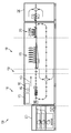
도 1 및 도 2는 이미지 용지(image-to-paper) 또는 직접 용지 인쇄 시스템(100)(이후, 인쇄 시스템(100)이라고 함.)을 도시한다. 인쇄 시스템(100)은 운반 구역(110), 기울기 보정 구역(130), 이미지 전사 구역(150), 하나 이상의 컨트롤러(170), 저장부(180), 기판 매체부(200; 도 2), 경화 유닛(210; 도 2), 및 출력 유닛(220; 도 2)를 포함할 수 있다. 인쇄 시스템의 구성요소 및 동작이 구역들과 관련하여 설명되어 있지만, 당해 기술분야의 숙련자는 구역들이 인쇄 시스템 내의 물리적인 구역을 형성할 수도 형성하지 않을 수도 있다는 것을 알 것이다. 인쇄 시스템은 인쇄 시스템(100)의 구성요소로부터 형성된 등록 시스템에 의해 시행될 수 있으며, 이 구성요소들은 인쇄 시스템(100)의 하나 이상의 구역 내에 분포될 수 있다. 등록 시스템은 기판 매체를 기울기 보정하도록 구성되고, 기판 매체의 횡방향 위치를 기초로 인쇄 프로세스를 조정하며, 잉크 분출과 기판 매체의 도달을 동기시킬 수 있도록 구성될 수 있다.1 and 2 illustrate an image-to-paper or direct paper printing system 100 (hereinafter referred to as printing system 100). The
운반 구역(110)은 기판 매체 피더(200; 도 2)로부터 기울기 보정 구역(130)으로 기판 매체(102)를 운반할 수 있는데, 기울어진 구역에서 기판 매체 피더(200)는 기판 매체를 저장 및 공급한다. 운반 구역(110)은 선등록 운반 닙(112; 이후 "운반 닙(112)"이라고 함.)을 포함하여 화살표(190)로 표시된 처리 방향으로 기판 매체(102)의 운반을 용이하게 할 수 있도록 되어 있다. 운반 닙(112)은 구동축(114) 주위에 지지될 수 있으며, 이 구동축은 구동모터(116)에 의해 회전 구동될 수 있다. 각각의 구동축(114)은 도 1에 화살표(195)로 표시된 것처럼 횡방향 또는 횡처리 방향을 따라 길이방향으로 연장될 수 있으며, 하나 이상의 운반 닙(112)을 지지할 수 있다. 구동모터(116)는 예를 들어, 구동축(114)에 작동가능하게 결합된 구동 벨트(118)를 사용하는 속도 프로파일을 기초로 하여 일정한 속도로 운반 닙(112)을 구동하도록 구성될 수 있다. 운반 닙(112)은 기판 매체 피더(200)로부터 운반 구역(110)으로 들어오는 기판 매체(102)를 맞물림하여 운반 구역(110)을 통해 기울기 보정 구역(130)을 향하여 기판 매체(102)를 몰고 갈 수 있도록 되어 있다. The
기울기 보정 구역(130)은 운반 구역(110)으로부터 수용된 기판 매체(102)를 수용할 수 있으며, 기판 매체(102)는 기울기 보정 구역(130) 내에서 기울기를 보정할 수 있다. 예를 들어, 기판 매체(102)는 기울기 보정 구역(130)에서 기울기를 보정할 수 있으므로, 기판 매체(102)의 선단 모서리(104) 및/또는 후단 모서리(106)는 (예를 들어, 횡처리 방향에 평행한) 처리 방향에 실질적으로 직각이 되도록 변위되며, 기판 매체(102)의 (예를 들어, 보드 내 및 보드 외 모서리와 같은) 측변 모서리(108)는 (예를 들어, 횡처리 방향에 직각인) 처리 방향에 실질적으로 평행하게 된다. 일부 실시예에서, 기판 매체(102)는 소정의 간극 내로 기울기 보정된다. 기울기 보정 구역(130)은 기울기 보정 롤러(132), 기울기 보정 롤러(134), 및 기울기 보정 센서(136)를 포함할 수 있다. 일부 실시예에서, 기울기 보정 롤러(132 및 134)는 기판 매체(102)가 이미지 전사 구역(150)으로 들어오기 전에 기판 매체(102)를 정렬함으로써 기판 매체(102)의 기울기를 조정할 수 있다. 기울기 보정 롤러(132 및 134)는 하나 이상의 기울기 보정 센서(136)의 출력에 응답하여 기판 매체를 정렬할 수 있다.The
기울기 보정 롤러(132)는 축(138) 주위에 지지될 수 있으며, 이 축은 구동 벨트(118)를 통하여 구동모터(116)에 작동 가능하게 결합될 수 있으므로, 기울기 보정 롤러(132)는 속도 프로파일에 따라 일정한 속도로 회전할 수 있게 된다. 구동축(138)은 횡처리 방향을 따라 길이방향으로 연장될 수 있다. 일부 실시예에서, 기울기 보정 롤러(132)는 운반 닙(112)과 실질적으로 동일한 속도로 회전하도록 구성될 수 있다. 본 실시예는 구동축(138) 상에 배치된 하나의 기울기 보정 롤러를 포함하고 있지만, 당해 기술분야의 숙련자는 추가의 기울기 보정 롤러가 구동축(138)에 의해 지지될 수 있다는 것을 알 수 있을 것이다. 더욱이, 당해 기술분야의 숙련자는 기울기 보정 롤러(132)가 구동모터(116)와 다른 구동모터에 의해 구동될 수 있다는 것을 알 것이다. 예를 들어, 일부 실시예에서, 기울기 보정 롤러(132)는 그 자체의 구동모터에 의해 구동될 수 있다. The
기울기 보정 롤러(134)는 횡처리 방향을 따라 길이방향으로 연장된 축(140) 주위에 지지될 수 있다. 일부 실시예에서, 구동축(140)은 구동 벨트(143)를 통해 가변 속도 구동모터(142; 이후 "구동모터(142)"라고 함)에 작동 가능하게 결합될 수 있다. 구동모터(142)는 검출된 기판 매체의 기울기를 수정하도록 가변 속도에서 기울기 보정 롤러(134)를 회전시키도록 구성될 수 있다. 일부 경우에, 구동모터(142)는 공칭 초기 속도로 기울기 보정 롤러(134)를 구동하도록 구성될 수 있으며, 이 속도는 기울기 보정 롤러(132)가 구동되는 속도와 실질적으로 동일할 수 있다. 일부 경우에, 구동모터(142)는 기판 매체(102)를 기울기 보정시킨 때와 같이, 공칭 초기 속도보다 더 작고 및/또는 큰 속도로 기울기 보정 롤러(134)를 구동하도록 구성될 수 있다. The
일부 실시예에서, 롤러(134)의 위치는 롤러(134)가 기판 매체를 맞물림하는 압력 및 롤러(134)가 회전하는 속도를 변화시키도록 기판 매체를 향하고 및/또는 기판 매체에서 멀어지게 롤러를 이동시키도록 조정될 수 있다. 이러한 접근을 사용하면, 기울기 보정는 가변 속도 구동모터에 의해 또는 구동모터에 의하지 않고 달성될 수 있다. 롤러(134)가 기판 매체를 맞물림하는 압력은 수정될 기판 매체의 기울기에 기초할 수 있다.In some embodiments, the position of the
본 실시예는 구동축(140) 주위에 지지된 하나의 기울기 보정 롤러를 포함하지만, 당해 기술 분야의 숙련자는 추가 기울기 보정 롤러가 구동축(140)에 의해 지지될 수 있다는 것을 알 것이다. 더욱이, 당해 기술 분야의 숙련자는 기울기 보정 롤러(132 및 134)가 둘 다 가변 속도 구동모터에 의해 제어될 수 있다는 것을 알 것이다. 아울러, 본 실시예가 축(138 및 140)에 의해 각각 지지된 롤러(132 및 134)를 예시하지만, 당해 기술분야의 숙련자는 추가 기울기 보정 롤러가 추가의 축에 의해 지지될 수 있으며, 추가 롤러가 구동모터(116), 구동모터(142)에 의해서 또는 다른 구동모터에 의해서 구동될 수 있다는 것을 알 것이다.Although this embodiment includes one tilt correction roller supported around the
본 실시예에서 기울기 보정 센서(144 및 146)를 포함하는 기울기 보정 센서(136)는 기판 매체(102)가 기울기 보정 구역(130)을 통과함에 따라 기판 매체(102)의 존재를 감지할 수 있다. 본 실시예에서, 기울기 보정 센서(136)는 기울기 보정 롤러(132 및 134)로부터 하류측에 배치되며, 횡처리 방향으로 직선형으로 배열된다. 기울기 보정 센서(136)는 선단 모서리(104)가 기울기 보정 센서(136)를 통과함에 따라 기판 매체(102)의 선단 모서리(104)를 검출할 수 있다. 기울기 보정 센서(136)가 본 실시예에서 기울기 보정 롤러(132 및 134)의 하류측에 있지만, 당해 기술분야의 숙련자는 기울기 보정 센서(136)가 기울기 보정 롤러(132 및 134)의 상류측에 위치할 수 있다는 것을 알 것이다. 더욱이, 당해 기술분야의 숙련자는 기울기 보정 센서(136)가 기판 매체(102)의 기울기를 검출한 때 기판 매체(102)의 선단 모서리(104), 후단 모서리(106), 보드 내 모서리 및/또는 보드 외 모서리를 검출할 수 있다는 것을 알 수 있다.In this embodiment, the tilt correction sensor 136 including the
각각의 기울기 보정 센서(144 및 146)가 실질적으로 동시에 및/또는 소정의 시기 내에 기판 매체(102)의 선단 모서리(104)를 검출하면, 인쇄 시스템(100)의 컨트롤러(170)는 기판 매체(102)가 기울어지지 않고 기울기 보정 롤러(132 및 134)가 실질적으로 동일한 속도로 구동되어 기판 매체(102)의 재정렬이 발생하지 않도록 (즉, 기판 매체가 기울기 보정되지 않도록) 하는 것을 결정할 수 있다.When each
기울기 보정 센서(136)의 하나가 다른 기울기 보정 센서(136) 중 하나 뒤에 및/또는 소정의 시기를 지나 기판 매체(102)의 선단 모서리(104)를 검출하면, 인쇄 시스템(100)의 컨트롤러(170)는 기판 매체(102)가 기울어진 것을 결정할 수 있다. 기판 매체의 기울기에 대한 결정에 따라, 인쇄 시스템(100)의 컨트롤러(170)는 기울기 보정 롤러(134)의 속도를 변화시킴으로써 기판 매체(102)를 기울기 보정시킬 수 있다. 일부 실시예에서, 기울기 보정 롤러(134)가 구동되는 속도는 기울기 보정 센서(136) 중 하나가 기판 매체(102)의 선단 모서리(104)를 감지한 때와 기울기 보정 센서(136)의 다른 하나가 기판 매체(102)의 선단 모서리를 감지한 때 사이의 시간차를 기초로 할 수 있다. 기울기 보정 롤러(134)가 회전하는 속도는 구동모터(142)가 롤러(134)를 회전시키는 속도를 변화시킴으로써 및/또는 기판 매체에 대한 롤러의 위치를 변화시킴으로써 변화될 수 있다.When one of the tilt correction sensors 136 detects the
하나의 예로서, 기판 매체(102)가 기울어져 센서(144)에 의한 선단 모서리(104)의 검출이 센서(146)에 의한 선단 모서리(104)의 검출을 지연시키게 되면, 구동모터(142)는 컨트롤러(170)에 의해 제어되어 기울기 보정 롤러(134)가 회전하는 속도를 감소시킬 수 있도록 되어 있다. 또 다른 예로서, 기판 매체(102)가 기울어져서 센서(146)에 의한 선단 모서리(104)의 검출이 센서(144)에 의한 선단 모서리(104)의 검출을 지연시키게 되면, 구동모터(142)는 컨트롤러(170)에 의해 제어되어 기울기 보정 롤러(134)가 회전하는 속도를 증가시킬 수 있도록 되어 있다.As one example, if the
본 실시예는 기판 매체를 기울기 보정하는 기술의 예시지만, 당해 기술분야의 숙련자는 기울기 보정 기판 매체에 대한 다른 방향의 접근이 시도될 수 있다는 것을 알 것이다. 예를 들어, 정지된 롤러는 기판 매체의 기울기를 보정하기 위해 사용될 수 있으며, 양 롤러(132 및 134)의 회전 속도가 변화할 수 있거나 롤러(132 및/또는 134)의 닙 압력이 변화할 수 있다.Although this embodiment is an illustration of a technique for tilt correcting a substrate medium, those skilled in the art will appreciate that other directions of access to the tilt correcting substrate medium may be attempted. For example, a stationary roller may be used to correct the tilt of the substrate medium, and the rotational speed of both
이미지 전사 구역(150)은 (예를 들어, 매체 전달 유닛과 같은) 매체 전달 벨트(152), 적어도 하나의 횡방향 매체 위치 센서(154; 이후 "횡방향 센서(154)"라고 함), 적어도 하나의 선단 모서리 센서(156), 및 인쇄부(158)를 포함할 수 있다. 기판 매체(102)는 기울기 보정 롤러(132 및 134)에 의해 이미지 전사 구역(150)의 매체 전달 벨트(152)로 전달된다. 일부 실시예에서, 매체 전달 벨트(152)는 정전 전달 벨트 또는 진공 전달 벨트가 될 수 있다.The
매체 전달 벨트(152)가 정전 전달 벨트로서 활용될 때, 정전 전하는 기판 매체를 정전 전달 벨트로 끌어당기는데 사용될 수 있다. 정전 전하는 기판 매체가 매체 전달 벨트로 "들러붙게" 하여 인쇄 프로세스 동안 기판 매체의 운동을 금지하도록 되어 있다. 기판 매체가 정전 전달 벨트 상에 있더라도, 기판 매체는 정전 전하로부터 야기된 인력을 극복한 기판 매체로 힘이 작용하지 않고 및/또는 정전 전하가 제거되지 않으면, 통상적으로 변위되지 않는다. 따라서, 기판 매체는 통상적으로 정전 전달 벨트 상에 배치되어 있어도 변위되지 않는다.When the
매체 전달 벨트(152)가 진공 전달 벨트인 때, 기판 매체를 진공 전달 벨트 상에 정위치로 유지하기 위해 흡착이 사용된다. 흡착은 기판 매체가 매체 전달 벨트에 "들러붙게" 하여 인쇄 프로세스 중에 기판 매체의 움직임을 금지시키도록 되어 있다. 기판 매체는 진공 전달 벨트 상에 있더라도, 흡착으로부터 야기된 인력을 극복한 기판 매체로 힘이 작용하지 않고 및/또는 흡착이 제거되지 않으면, 통상적으로 변위되지 않는다. 따라서, 기판 매체는 통상적으로 진공 전달 벨트 상에 배치되어 있어도 변위되지 않는다.When the
기판 매체(102)가 기울기 보정 구역(130)으로부터 이미지 전사 구역(150)으로 통과함에 따라, 횡방향 센서(154)는 기판 매체(102)의 횡방향 위치를 검출할 수 있다. 횡방향 센서(154)는 매체 전달 벨트(152)의 일 측변 상에 위치될 수 있다. 예를 들어, 본 실시예에서, 횡방향 센서(154)는 매체 전달 벨트(152)의 보드 내 측변(164) 상에 위치된다. 일부 실시예에서, 횡방향 센서(154)는 매체 전달 벨트(152)의 보드 외 측변(166) 상에 위치될 수 있다.As the
일부 실시예에서, 횡방향 센서(154)는 기울기 보정된 기판 매체가 기대한, 의도된, 및/또는 원하는 횡방향 위치로부터 벗어나는 거리를 검출할 수 있으며, 컨트롤러(170)로 횡방향 센서 신호를 출력할 수 있다. 일부 실시예에서, 횡방향 센서(154)는 기판 매체의 횡방향 위치를 검출할 수 있으며, 컨트롤러(170)로 횡방향 센서 신호를 출력할 수 있다. 횡방향 센서(154)의 출력 신호는 인쇄부(158)에 의해 잉크의 위치설정을 조정함으로써, 운반 벨트 상의 기판 매체의 재정렬 또는 기판 매체 상에 배치되는 이미지의 휨을 필요로 하지 않으면서 기판 매체(102)에 대하여 이미지의 횡방향 등록을 수행하도록 컨트롤러(170)에 의해 사용될 수 있다. 이러한 방식으로, 횡방향 처리 등록은 기판 매체의 횡방향 위치의 검출과, 기판 매체의 횡방향 위치를 보정하기 위한 인쇄부에서의 잉크 분출의 조정에 따라 달성될 수 있다. 당해 기술분야의 숙련자는 다른 시행방법이 기판 매체의 횡방향 위치를 검출하는데 사용될 수 있다는 것을 알 것이다.In some embodiments,
기판 매체(102)가 처리 방향으로 계속됨에 따라, 모서리 센서(156)는 예를 들어, 기판 매체(102)의 선단 모서리(104) 및/또는 후단 모서리(106)를 모서리 센서(156)를 통과하는 동안 검출함으로써 기판 매체의 처리 방향 위치가 정해진 때를 검출할 수 있다. 처리 방향 위치가 검출된 상태에서, 모서리 센서(156)는 컨트롤러로 모서리 센서 신호를 출력할 수 있으며, 이 신호는 인쇄부(158)에 의해 잉크의 분출이 개시되는 시점을 결정하도록 컨트롤러에 의해 사용될 수 있다. 일부 실시예에서, 횡방향 센서(154) 및 모서리 센서(156)는 단일 센서 또는 통합 센서로서 활용될 수 있다. 센서들은 포인트 센서 및/또는 어레이 센서로서 활용될 수 있다. 당해 기술분야의 숙련자는 시트의 처리 방향 위치가 시트의 선단 모서리를 검출하도록 위치된 센서를 제공하는 대신 또는 제공함과 더불어 시트의 후단 에지와 인접 위치된 센서를 사용하여 선택적으로 검출될 수 있다는 것을 알 것이다.As the
인쇄부(158)는 하나 이상의 인쇄 헤드(160)를 포함할 수 있다. 인쇄 헤드(160)는 기판 매체(102)가 매체 운반 벨트(152)에 의해 인쇄부(158)를 통과하여 운반됨에 따라 기판 매체(102) 상에 잉크를 방출하도록 동작할 수 있다. 일부 실시예에서, 인쇄 헤드(160)는 페이지폭 크기의 인쇄 헤드로서 형성될 수 있으므로, (예를 들어, 횡처리 방향의 기판 매체의 폭과 같은) 기판 매체의 횡방향 폭은 인쇄 헤드로부터 잉크를 수용할 수 있도록 되어 있다. 일부 실시예에서, 인쇄 헤드(160)는 기판 매체의 횡방향 폭보다 더 넓을 수 있으며 및/또는 인쇄 헤드(160)는 횡처리 방향으로 변위될 수 있다. 인쇄 헤드(160)는 기판 매체 상에 동일 및/또는 상이한 색상의 잉크를 분사할 수 있다. 예를 들어, 일부 실시예에서, 각각의 인쇄 헤드(160)는 기판 매체 상에 서로 다른 색상의 잉크를 방출할 수 있으므로, 인쇄 시스템은 다색 프린터일 수 있다.The
잉크의 분사 타이밍은 모서리 센서(156)에 의한 기판 매체의 처리 방향 위치의 검출에 기초할 수 있다. 예를 들어, 컨트롤러(170)는 모서리 센서(156)에 의한 선단 모서리(104) 및/또는 후단 모서리(106)의 검출로부터 소정의 시간이 경과한 후, 기판 매체(102) 상에 잉크를 분사하기 위해 인쇄 헤드(160)에 명령을 내리도록 구성될 수 있다. 일부 실시예에서, 소정의 시간은 모서리 센서(156)와 인쇄부(158) 사이의 거리 뿐만 아니라 매체 운반 벨트(152)가 처리 방향으로 기판 매체(102)를 운반하는 속도를 기초로 할 수 있다. 또 다른 실시예에서, 운반 벨트(152)의 구동축 상의 암호기는 처리 방향 위치가 측정되고 암호기로부터의 신호가 잉크 젯 인쇄 노즐의 분사를 촉발하는데 사용될 수 있으므로, 매체가 이동한 거리를 추측하는데 사용될 수 있다.The ejection timing of the ink may be based on the detection of the processing direction position of the substrate medium by the
이러한 방식으로, 처리 방향 등록은 매체의 선단 모서리 및/또는 후단 모서리를 감지하고, 인쇄 헤드(160)의 분사를 조정하여, 기판 매체 상에 배치되는 이미지를 휘게 하지 않도록 하고 처리 방향으로의 기판 매체 위치 상의 오류를 수정하도록 기판 매체를 조정하지 않도록 하면서 기판 매체의 위치와 타이밍을 일치시키게 되는 것에 따라 달성될 수 있다. 시트 절단(cut-sheet) 잉크 젯 시스템으로서 활용된 실시예에 있어서, 인쇄부로 기판 매체(102)를 나르기 위해 정밀한 타이밍 또는 운율(cadence)이 필요하지는 않다. 기판 매체(102)는 타이밍 오류를 갖고 도착할 수 있으며, 처리 방향 등록에 있어서는 여전히 정확하게 이미지화될 수 있다. In this way, the processing direction registration senses the leading edge and / or trailing edge of the medium, adjusts the ejection of the
하나 이상의 컨트롤러(170)가 인쇄 시스템(100) 내에서 등록 프로세스(182)를 용이하게 하도록 활용될 수 있다. 하나 이상의 컨트롤러(170)는 롤러(112,132 및 134)의 회전을 제어하기 위해 구동모터(116 및/또는 142)와; 센서 신호를 수신 및 처리하기 위해 센서(136,154 및 156)와; 잉크 방출을 제어하기 위해 인쇄 헤드(160)와; 그리고 비일시적 컴퓨터 판독가능 저장매체로서 활용될 수 있는 저장부(180)와 연결될 수 있다. 저장부(180)는 인쇄 시스템(100)의 하나 이상의 컨트롤러에 의해 실행된 때 등록 시스템이 등록 프로세스(182)를 활용하도록 하는 명령을 저장할 수 있다. 비일시적 컴튜터 판독가능 저장매체의 몇 가지 예로는 플로피 드라이브, 하드 드라이브, 컴팩트 드라이브, 테이프 드라이브, 플래시 드라이브, 광학 드라이브, 리드 온리 메모리(ROM), 랜덤 어세스 메모리(RAM) 등이 포함된다. One or
도 2를 참조하면, 경화 유닛(210)은 인쇄부(158)의 하류측에 있을 수 있으며, 인쇄 헤드(160)에 의해 기판 매체 상에 방출되는 잉크를 경화시키는데 사용될 수 있다. 경화 유닛은 예를 들어, 자외선, 적외선, 및/또는 기타 발열 기술을 사용하여 발생된 열을 사용할 수 있다. 출력 유닛(220)은 경화 유닛(210)의 하류 측이 될 수 있으며, 경화 유닛(210)에 의해 이미지가 위에 경화되게 하는 기판 매체를 수용할 수 있다. 출력 유닛(220)은 기판 매체를 출력할 수 있다.Referring to FIG. 2, the
도 3을 참조하면, 하나 이상의 배열로 인해 헤드(160)의 바닥을 횡단하여 분포된 인쇄 노즐(302)을 포함할 수 있다. 잉크는 인쇄 노즐(302)로부터 선택적으로 분사되어 기판 매체(102) 상에 이미지를 인쇄할 수 있도록 되어 있다. 인쇄 헤드(160)는 이미지를 인쇄하는데 사용된 노즐 세트가 하나 이상의 노즐 또는 픽셀만큼 변위되어, 기판 매체의 측정된 횡방향 위치와 일치할 수 있도록 하기에 충분한 크기와 밀도를 갖는 인쇄 노즐 어레이를 포함한다. 인쇄 헤드(160)는 기판 매체 상의 위치에 기초하여 선택된 인쇄 노즐(302)로부터 잉크를 분사하도록 제어될 수 있다. 예를 들어, 인쇄 노즐(302)의 초기 세트(304)는 횡방향으로 벗어난 기판 매체에 대한 보정이 이루어지지 않은 때 선택될 수 있으며 인쇄 노즐의 다른 세트(306)는 기판 매체의 횡방향 이탈에 상응하는 보정이 이루어진 때 선택될 수 있다.Referring to FIG. 3, one or more arrangements may include
예를 들어, 횡방향 센서(14)의 출력에 따라 컨트롤러(170)는 선택된 인쇄 노즐이 횡처리 방향으로 검출된 기판 매체의 이탈을 보정하여 잉크를 분사하도록 인쇄 헤드(160)를 제어할 수 있다. 일부 실시예에서, 인쇄 헤드(160)는 횡처리 방향으로 검출된 기판 매체의 이탈을 보정하여 기판 매체의 횡방향 위치를 보정하도록 횡처리 방향으로 변위될 수 있다. 따라서, 횡방향 매체 등록은 이미지 기록 및/또는 횡처리 방향으로의 인쇄 헤드(160)의 변위 시 사용할 적절한 노즐의 하위조합을 선택함으로써 달성될 수 있다. 이러한 접근을 사용하여 잉크의 분사에 의해 기판 매체 상에 배치되는 이미지는 기판 매체의 횡방향 위치를 보정하도록 횡처리 방향으로 일정하게 변위되므로, 기판 매체에 배치되는 이미지가 휘지 않게 된다. For example, according to the output of the transverse sensor 14, the
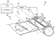
도 4는 기판 매체 등록이 활용될 수 있는 인쇄 시스템(400)이 기판 매체의 기울기를 보정하고, 기판 매체의 횡방향 위치에 기초하여 인쇄 프로세스를 조정하며, 기판 매체의 도착과 잉크 분출을 동기시키는 것을 도시한다. 인쇄 시스템(400)은 운반 구역(410), 기울기 보정 구역(430), 및 이미지 전사 구역(450)을 포함할 수 있다. 운반 구역은 운반 롤러(412)를 사용하여 기울기 보정 구역(430)을 향하여 화살표(490)로 표시된 처리 방향으로 기판 매체(402)를 운반할 수 있다. 기울기 보정 구역(430)은 기판 매체(402)를 수용할 수 있으며, 정지된 기울기 보정 롤러(432)를 사용하여 기판 매체의 기울기를 보정할 수 있는데, 이 롤러는 기판 매체의 선단 모서리(404)의 기울기를 보정하도록 처리 방향으로 기판 매체(402)의 진행에 저항을 일으킨다. 기울기 보정 기판 매체는 이미지 전사 구역(450)의 (예를 들어, 매체 운반 유닛과 같은) 회전 매체 드럼(452)으로 전달된다. 일부 실시예에서, 드럼(452)은 매체 진공 드럼이 될 수 있다. 일부 실시예에서, 드럼(452)은 정전 매체 드럼이 될 수 있다.4 shows a
드럼(452)이 정전 매체 드럼으로서 활용될 때, 정전 전하는 기판 매체를 드럼으로 끌어당기는데 사용될 수 있다. 정전 전하는 인쇄 프로세스 동안 기판 매체의 움직임을 금지하도록 기판 매체가 드럼에 "들러 붙게" 한다. 기판 매체가 정전 드럼 상에 위치하더라도, 기판 매체는 정전 전하로부터 야기된 인력을 극복한 기판 매체로 힘이 작용하지 않고 및/또는 정전 전하가 제거되지 않으면, 통상 변위되지 않는다.When
드럼(452)이 진공 매체 드럼인 때, 흡착은 기판 매체가 드럼 상에 정위치로 유지되도록 하는데 사용될 수 있다. 흡착은 기판 매체가 드럼에 "들러붙게" 하여 인쇄 프로세스 동안 기판 매체의 움직임을 금지하도록 되어 있다. 기판 매체는 드럼 상에 있더라도, 흡착으로부터 야기된 인력을 극복한 기판 매체로 힘이 작용하지 않고 및/또는 흡착이 제거되지 않으면, 통상 변위되지 않는다.When the
하나 이상의 인쇄 헤드(454)는 기판 매체가 인쇄 헤드(454)를 통과함에 따라 기판 매체 상으로 잉크를 분출하도록 드럼(452) 주위로 분포될 수 있다. 일부 실시예에서, 기판 매체(402)는 여러 차례의 회전 동안 드럼(452) 상에 남아 있을 수 있으므로, 기판 매체 상에 이미지를 형성하도록 한 차례 이상 인쇄 헤드를 통과하게 된다. 인쇄 헤드는 인쇄 노즐 어레이(456)를 포함할 수 있다. 잉크는 기판 매체(402) 상에 이미지를 인쇄하도록 인쇄 노즐(456)로부터 선택적으로 분사될 수 있다. 인쇄 헤드(454)는 이미지를 인쇄하기 위해 사용되는 노즐 세트가 기판 매체의 측정된 횡방향 위치와 일치하게 하나 이상의 픽셀만큼 변위될 수 있도록 하기에 충분한 크기와 밀도의 인쇄 노즐 어레이를 포함한다. 인쇄 헤드(454)는 드럼(452) 상의 기판 매체(402)의 횡방향 위치를 기초로 선택된 인쇄 노즐(456)로부터 잉크를 분사하도록 제어될 수 있다.One or more print heads 454 may be distributed around the
드럼 상의 기판 매체의 위치는 횡방향 센서(458)에 의해 검출될 수 있다. 센서(458)의 출력에 따라, 컨트롤러(470)는 저장부(480) 내의 등록 프로세스(482)를 기초로 인쇄 헤드(454)를 제어할 수 있으므로, 선택된 인쇄 노즐은 횡처리 방향으로 검출된 기판 매체(402)의 이탈을 보정하도록 잉크를 분사하게 된다. 일부 실시예에서, 인쇄 헤드(454)는 횡처리 방향으로 검출된 기판 매체(402)의 이탈을 보정하기 위해 기판 매체(402)의 횡방향 위치를 보정하도록 횡처리 방향으로 변위될 수 있다. 따라서, 횡방향 매체 등록은 이미지 기록 및/또는 횡처리 방향으로의 인쇄 헤드(454)의 변위 시 사용할 적절한 인쇄 노즐의 하위조합을 선택함으로써 달성될 수 있다. 이러한 접근을 사용하여 잉크의 분사에 의해 기판 매체 상에 배치되는 이미지는 기판 매체의 횡방향 위치를 보정하도록 횡처리 방향으로 일정하게 변위되므로, 기판 매체에 배치되는 이미지는 휘지 않게 된다. The position of the substrate medium on the drum can be detected by the
횡방향 센서(458)는 또한 처리 방향 위치 센서로서 동작할 수 있으며, 또는 개별 모서리 센서(460)는 기판 매체의 (예를 들어, 선단 모서리 및/또는 후단 모서리와 같은) 처리 방향 위치를 감지하는데 사용될 수 있다. 잉크 분사 타이밍은 센서(458 또는 460)에 의한 기판 매체 선단 모서리의 검출을 기초로 할 수 있다. 예를 들어, 컨트롤러(470)는 저장부(480) 내에 저장된 등록 프로세스를 기초로 하여 센서(458 또는 460)에 의해 선단 모서리(404)가 검출된 때로부터 소정 시간이 경과한 뒤, 기판 매체(402) 상에 잉크를 분사하도록 인쇄 헤드(454)에 명령을 내리게 구성될 수 있다. 일부 실시예에서, 소정 시간은 드럼(452)이 회전하는 속도 뿐만 아니라 선단 모서리를 검출하는데 사용된 센서와 인쇄 헤드(454) 사이의 거리를 기초로 할 수 있다. 일부 실시예에서, 드럼 상의 암호기는 매체의 선단 모서리가 검출되었기 때문에 드럼이 회전한 거리를 측정하는데 사용될 수 있으며 암호기로부터의 신호는 인쇄 노즐로부터의 잉크 분사를 촉발하는데 사용될 수 있다. 이러한 방식으로, 처리 방향 등록은 매체의 선단 모서리를 감지하고, 인쇄 헤드(454)의 분사를 조정하여, 기판 매체 상에 배치되는 이미지를 휘게 하지 않도록 하고 처리 방향으로의 기판 매체 위치 상의 오류를 수정하도록 기판 매체를 조정하지 않도록 하면서 기판 매체의 위치와 타이밍을 일치시키게 되는 것에 따라 달성될 수 있다.The
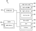
도 5는 인쇄 시스템(100 및/또는 400)과 같은 인쇄 시스템을 위한 예시적인 등록 시스템(500)의 블럭도를 도시한다. 등록 시스템(500)은 하나 이상의 컨트롤러(510), 등록 프로세스(182 및/또는 482)와 같은 등록 프로세스(522)를 저장하는 저장부(520), 기울기 보정 시스템(530), 및 반사 시스템(550)을 포함할 수 있다. 등록 시스템(500)의 구성요소는 인쇄 시스템의 하나 이상의 구역 내에 분포될 수 있다. 등록 시스템(500)은 기판 매체의 기울기를 보정하고, 기판 매체의 횡방향 위치에 기초하여 횡처리 방향 또는 횡방향으로의 잉크 분출을 조정하며, 잉크의 분출을 기판 매체의 도착과 동기시키도록 구성될 수 있다. 등록 시스템(500)의 실시예는 횡처리 방향 및 처리 방향 오류 수정하기 위해 기판 매체를 변위시키지 않고도 또한 기판 매체 상에 배치되는 이미지를 휘게 하지 않고도 기울기, 횡방향 위치 오류, 및 처리 방향 오류에 대하여 기판 매체를 등록할 수 있다.5 shows a block diagram of an
본 실시예에서, 기울기 보정 시스템(530)은 롤러(132 및 134)와 같은 기울기 보정 롤러(532) 또는 정지 롤러(432)와 같은 기울기 보정 롤러를 포함할 수 있으며, 반사 시스템(550)은 센서(154,156,458 및/또는 460)와 같은 센서(552), 및 인쇄 헤드(160) 또는 인쇄 헤드(454)와 같은 인쇄 헤드(554)를 포함할 수 있다. 일부 실시예에서, 기울기 보정 시스템(530)은 또한 기울기 보정 센서(136)와 같은 기울기 보정 센서(532), 및 구동모터(142)와 같은 가변 속도 구동모터(536)를 포함할 수 있다. 컨트롤러(510), 저장부(520), 및 기울기 보정 시스템(530)과 반사 시스템(550)의 구성요소는 여기에서 설명한 바와 같이 활용될 수 있다.In the present embodiment, the
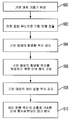
도 6은 인쇄 시스템(100 및/또는 400)과 같은 인쇄 시스템의 등록 시스템(500)에 의해 활용되는 등록 프로세스의 예시적인 실시예를 도시하는 흐름도이다. 등록 프로세스는 이미지를 휘게 하지 않으면서 달성된다. 인쇄 시스템을 통해 운반되는 기판 매체는 기울기 보정 시스템(600)에 의해 기울기가 보정된다. 기울기 보정 시스템은 기판 매체가 기울어진 것을 검출함에 따라 기판 매체의 기울기를 보정할 수 있다. 기판 매체가 기울기 보정된 이후, 기판 매체는 기판 매체의 위치가 고정되는 매체 운반 유닛(602)으로 전달된다. 기울기가 보정된 기판 매체의 횡방향 위치는 반사 시스템(604)을 사용하여 감지되며, 인쇄 시스템의 인쇄 헤드 내 노즐의 서브 세트는 컨트롤러(606)에 의해 기판 매체의 횡방향 위치를 보정하도록 선택된다. 이러한 접근을 사용하여 잉크의 분사에 의해 기판 매체 상에 배치되는 이미지는 기판 매체의 횡방향 위치를 보정하도록 횡처리 방향으로 일정하게 변위될 수 있으므로, 기판 매체에 배치되는 이미지는 휘지 않게 된다. 기판 매체의 (예를 들어, 선단 모서리 및/또는 후단 모서리와 같은) 처리 방향 위치는 반사 시스템(608)을 사용하여 감지되며, 잉크는 처리 방향 위치(610)의 방향을 기초로 하여 인쇄 헤드로부터 분사된다. 6 is a flowchart illustrating an exemplary embodiment of a registration process utilized by a
Claims (10)
복수의 인쇄 노즐을 구비한 인쇄 헤드;
인쇄 헤드를 통과하도록 기판 매체를 운반하는 매체 운반 유닛;
기판 매체의 기울기를 보정하기 위해 적어도 하나의 롤러를 가진 기울기 보정 시스템;
기판 매체가 매체 운반 유닛에 의해 처리 방향으로 운반됨에 따라 기판 매체의 적어도 하나의 선단 및 후단 모서리와 매체 운반 유닛 상의 기판 매체의 횡방향 위치를 검출하는 하나 이상의 센서를 가진 반사 시스템; 및
인쇄 헤드 및 반사 시스템에 작동 가능하게 결합되며, 잉크가 매체 운반 유닛 상의 기판 매체의 횡방향 위치를 기초로 하여 잉크가 분사되는 인쇄 노즐의 서브 세트 (subset) 를 선택하고, 기판 매체의 적어도 하나의 선단 모서리 및 후단 모서리를 검출함에 따라 인쇄 노즐의 서브 세트로부터 잉크가 분사되는 시점을 결정하는 컨트롤러
를 포함하는 것을 특징으로 하는 직접 표시 인쇄 시스템.A direct display printing system configured for substrate media registration without warping the image,
A print head having a plurality of print nozzles;
A media conveying unit for conveying the substrate medium to pass through the print head;
A tilt correction system having at least one roller for correcting a tilt of the substrate medium;
A reflection system having at least one leading and trailing edge of the substrate medium and one or more sensors for detecting the transverse position of the substrate medium on the medium carrying unit as the substrate medium is carried in the processing direction by the medium carrying unit; And
Operatively coupled to the print head and the reflective system, the ink selects a subset of the print nozzles from which the ink is ejected based on the transverse position of the substrate medium on the media transport unit, and at least one of the substrate media Controller that determines when ink is ejected from a subset of print nozzles by detecting leading and trailing edges
Direct display printing system comprising a.
상기 기울기 보정 시스템은 기울기 보정 센서와 기울기 보정 롤러를 포함하며, 기울기 보정 센서는 기판 매체가 기울어졌는지 여부를 검출하고, 기울기 보정 시스템이 매체 운반 유닛에 의한 기판 매체의 수용에 앞서 기판 매체의 기울기를 보정하기 위해, 제1 기울기 보정 롤러는 제1 속도로 구동되고, 기판 매체가 기울어진 것을 검출하는 기울기 보정 센서에 응답하여 제1 기울기 보정 롤러의 제1 속도에 대해 상대적으로 조정되는 제2 속도로 구동되는 것을 특징으로 하는 직접 표시 인쇄 시스템.The method of claim 1,
The tilt correction system includes a tilt correction sensor and a tilt correction roller, the tilt correction sensor detects whether the substrate medium is tilted, and the tilt correction system tilts the substrate medium prior to receiving the substrate medium by the medium carrying unit. To correct, the first tilt correction roller is driven at a first speed and at a second speed adjusted relative to the first speed of the first tilt correction roller in response to a tilt correction sensor detecting that the substrate medium is tilted. Direct display printing system, characterized in that driven.
상기 컨트롤러는 기울기 보정 시스템에 작동 가능하게 결합되어, 제2 모터가 매체의 기울기를 보정하기 위해, 제1 기울기 보정 롤러의 속도가 일정하게 되도록 제어하고, 제2 기울기 보정 롤러를 회전시키는 속도를 제어하도록 되어 있는 것을 특징으로 하는 직접 표시 인쇄 시스템.The method of claim 2,
The controller is operatively coupled to the tilt correction system, so that the second motor controls the speed of the first tilt correction roller to be constant so as to correct the tilt of the medium, and controls the speed of rotating the second tilt correction roller. Direct display printing system, characterized in that the
상기 컨트롤러는 잉크가 분사되는 인쇄 노즐의 서브 세트를 선택하여, 인쇄 헤드에 의해 형성되는 이미지를 기판 매체의 횡방향 위치와 정렬시키는 것을 특징으로 하는 직접 표시 인쇄 시스템.The method of claim 1,
And said controller selects a subset of print nozzles from which ink is ejected to align the image formed by the print head with the transverse position of the substrate medium.
기판 매체의 적어도 하나의 선단 모서리 및 후단 모서리의 검출을 기초로 한 인쇄 헤드로부터의 잉크 분사 타이밍에 의해 처리 방향 등록이 제어되는 것을 특징으로 하는 직접 표시 인쇄 시스템.The method of claim 1,
The direct display printing system characterized in that the processing direction registration is controlled by the ink ejection timing from the print head based on detection of at least one leading edge and trailing edge of the substrate medium.
하나 이상의 센서는 상기 매체의 모서리를 검출함으로써 횡방향 센서로서 기능하는 것을 특징으로 하는 시스템.The method of claim 1,
At least one sensor functions as a transverse sensor by detecting an edge of the medium.
기판 매체의 기울기를 보정하기 위해 구성된 기울기 보정 시스템;
처리 방향으로 운반되는 기판 매체의 적어도 하나의 선단 모서리 및 후단 모서리와 기판 매체의 횡방향 위치를 검출하도록 구성된 반사 시스템; 및
반사 시스템에 작동 가능하게 결합되어, 기판 매체의 적어도 하나의 선단 모서리 및 후단 모서리와 기판의 횡방향 위치를 검출함에 따라 반사 시스템의 인쇄 헤드로부터의 잉크 분사를 제어하도록 구성되는 컨트롤러
를 포함하는 것을 특징으로 하는 기판 매체 등록 시스템.In a substrate medium registration system in a printing system,
A tilt correction system configured to correct a tilt of the substrate medium;
A reflection system configured to detect at least one leading and trailing edge of the substrate medium and the transverse position of the substrate medium carried in the processing direction; And
A controller operatively coupled to the reflective system, the controller configured to control ink jetting from the print head of the reflective system in response to detecting at least one leading and trailing edge of the substrate medium and the transverse position of the substrate
Substrate medium registration system comprising a.
상기 기울기 보정 시스템은 기울기 보정 센서와 기울기 보정 롤러를 포함하며, 기울기 보정 센서는 기판 매체가 기울어졌는지 여부를 검출하며, 기울기 보정 시스템이 매체 운반 벨트에 의한 기판 매체의 수용에 앞서 기판 매체의 기울기를 보정하기 위해 기판 매체가 기울어진 것을 검출하는 기울기 보정 센서에 응답하여 제1 기울기 보정 롤러가 제2 기울기 보정 롤러와 다른 속도로 구동되는 것을 특징으로 하는 기판 매체 등록 시스템.The method of claim 7, wherein
The tilt correction system includes a tilt correction sensor and a tilt correction roller, the tilt correction sensor detects whether the substrate medium is tilted, and the tilt correction system tilts the substrate medium prior to receiving the substrate medium by the medium carrying belt. And the first tilt correction roller is driven at a different speed than the second tilt correction roller in response to a tilt correction sensor detecting that the substrate medium is tilted to correct.
상기 기울기 보정 시스템은 적어도 하나의 구동모터를 포함하고, 상기 컨트롤러는 기울기 보정 시스템에 작동 가능하게 결합되어, 적어도 하나의 기울기 보정 롤러를 회전시키는 적어도 하나의 구동 모터의 속도를 제어하는 것을 특징으로 하는 기판 매체 등록 시스템.The method of claim 8,
The tilt correction system includes at least one drive motor, and the controller is operatively coupled to the tilt correction system to control the speed of at least one drive motor for rotating the at least one tilt correction roller. Substrate Media Registration System.
상기 기울기 보정 시스템은 기판 매체의 선단 모서리가 인쇄 시스템의 횡처리 방향과 실질적으로 평행하도록 또는 측변 모서리가 인쇄 시스템의 처리 방향과 실질적으로 평행하도록 기판 매체를 정렬하고, 상기 컨트롤러는 기판 매체 상에 배치되는 이미지가 기판 매체와 적절하게 정렬되도록 기판 매체의 횡방향 위치를 기초로 하여 기판 매체 상에 배치되는 이미지의 횡방향 위치를 조정하는 것을 특징으로 하는 기판 매체 등록 시스템.
The method of claim 7, wherein
The tilt correction system aligns the substrate medium such that the leading edge of the substrate medium is substantially parallel to the transverse direction of the printing system or the side edge is substantially parallel to the processing direction of the printing system, and the controller is disposed on the substrate medium. And lateral position of an image disposed on the substrate medium based on the lateral position of the substrate medium such that the image to be properly aligned with the substrate medium.
Applications Claiming Priority (2)
| Application Number | Priority Date | Filing Date | Title |
|---|---|---|---|
| US12/911,129 | 2010-10-25 | ||
| US12/911,129 US8469476B2 (en) | 2010-10-25 | 2010-10-25 | Substrate media registration system and method in a printing system |
Publications (1)
| Publication Number | Publication Date |
|---|---|
| KR20120042693A true KR20120042693A (en) | 2012-05-03 |
Family
ID=45219897
Family Applications (1)
| Application Number | Title | Priority Date | Filing Date |
|---|---|---|---|
| KR1020110108683A KR20120042693A (en) | 2010-10-25 | 2011-10-24 | Direct marking printing system and substrate media registration system in printing system |
Country Status (6)
| Country | Link |
|---|---|
| US (1) | US8469476B2 (en) |
| JP (1) | JP2012091511A (en) |
| KR (1) | KR20120042693A (en) |
| CN (1) | CN102555532B (en) |
| DE (1) | DE102011084739A1 (en) |
| GB (1) | GB2485037A (en) |
Cited By (2)
| Publication number | Priority date | Publication date | Assignee | Title |
|---|---|---|---|---|
| KR20190132206A (en) * | 2018-05-17 | 2019-11-27 | 제록스 코포레이션 | System and method for de-skewing substrates and laterally registering images on the substrates in a printer |
| WO2020060082A1 (en) * | 2018-09-19 | 2020-03-26 | 주식회사 직지 | Rotary drum printing device |
Families Citing this family (39)
| Publication number | Priority date | Publication date | Assignee | Title |
|---|---|---|---|---|
| US10632740B2 (en) | 2010-04-23 | 2020-04-28 | Landa Corporation Ltd. | Digital printing process |
| US9902147B2 (en) | 2012-03-05 | 2018-02-27 | Landa Corporation Ltd. | Digital printing system |
| US9498946B2 (en) | 2012-03-05 | 2016-11-22 | Landa Corporation Ltd. | Apparatus and method for control or monitoring of a printing system |
| US10569534B2 (en) | 2012-03-05 | 2020-02-25 | Landa Corporation Ltd. | Digital printing system |
| US9643403B2 (en) | 2012-03-05 | 2017-05-09 | Landa Corporation Ltd. | Printing system |
| EP4019596A1 (en) | 2012-03-05 | 2022-06-29 | Landa Corporation Ltd. | Method for manufacturing an ink film construction |
| US10642198B2 (en) | 2012-03-05 | 2020-05-05 | Landa Corporation Ltd. | Intermediate transfer members for use with indirect printing systems and protonatable intermediate transfer members for use with indirect printing systems |
| US10434761B2 (en) | 2012-03-05 | 2019-10-08 | Landa Corporation Ltd. | Digital printing process |
| JP6393190B2 (en) | 2012-03-15 | 2018-09-19 | ランダ コーポレイション リミテッド | Endless flexible belt for printing system |
| US9682573B2 (en) * | 2012-04-16 | 2017-06-20 | Xerox Corporation | Printer having edge control apparatus for web media |
| US8915497B2 (en) | 2013-01-04 | 2014-12-23 | Tamarack Products, Inc. | Method and apparatus for sheet and carton blank aligning using caster effect |
| WO2014107897A1 (en) * | 2013-01-14 | 2014-07-17 | Hewlett-Packard Development Company, L.P. | Media alignment |
| GB201401173D0 (en) | 2013-09-11 | 2014-03-12 | Landa Corp Ltd | Ink formulations and film constructions thereof |
| DE102016202118A1 (en) * | 2015-03-19 | 2016-09-22 | Heidelberger Druckmaschinen Ag | Additional sheet edge sensor |
| GB2536489B (en) | 2015-03-20 | 2018-08-29 | Landa Corporation Ltd | Indirect printing system |
| GB2537813A (en) | 2015-04-14 | 2016-11-02 | Landa Corp Ltd | Apparatus for threading an intermediate transfer member of a printing system |
| CN108367578B (en) * | 2015-12-08 | 2021-02-12 | 惠普发展公司有限责任合伙企业 | Media alignment calibration |
| US10933661B2 (en) | 2016-05-30 | 2021-03-02 | Landa Corporation Ltd. | Digital printing process |
| GB201609463D0 (en) | 2016-05-30 | 2016-07-13 | Landa Labs 2012 Ltd | Method of manufacturing a multi-layer article |
| US11260681B2 (en) | 2017-02-07 | 2022-03-01 | Hewlett-Packard Development Company, L.P. | Print medium position detection |
| US10277756B2 (en) | 2017-09-27 | 2019-04-30 | Xerox Corporation | Apparatus and method for overcoating a rendered print |
| CN111212736B (en) | 2017-10-19 | 2021-11-23 | 兰达公司 | Endless flexible belt for a printing system |
| JP6977479B2 (en) * | 2017-10-30 | 2021-12-08 | コニカミノルタ株式会社 | Drive device and image forming device |
| WO2019097464A1 (en) | 2017-11-19 | 2019-05-23 | Landa Corporation Ltd. | Digital printing system |
| US11511536B2 (en) | 2017-11-27 | 2022-11-29 | Landa Corporation Ltd. | Calibration of runout error in a digital printing system |
| US11707943B2 (en) | 2017-12-06 | 2023-07-25 | Landa Corporation Ltd. | Method and apparatus for digital printing |
| WO2019111223A1 (en) | 2017-12-07 | 2019-06-13 | Landa Corporation Ltd. | Digital printing process and method |
| US10442219B2 (en) * | 2018-01-16 | 2019-10-15 | Xerox Corporation | Dual edge registered sheets to mitigate print head jet dry out on short sheets within inkjet cut sheet printing |
| US10894681B2 (en) * | 2018-04-26 | 2021-01-19 | Xerox Corporation | Sheet registration using rotatable frame |
| CN112399918B (en) | 2018-06-26 | 2023-01-31 | 兰达公司 | Intermediate transmission member of digital printing system |
| WO2020023030A1 (en) | 2018-07-25 | 2020-01-30 | Hewlett-Packard Development Company, L.P. | Media sheet skew correction |
| US10994528B1 (en) | 2018-08-02 | 2021-05-04 | Landa Corporation Ltd. | Digital printing system with flexible intermediate transfer member |
| US11318734B2 (en) | 2018-10-08 | 2022-05-03 | Landa Corporation Ltd. | Friction reduction means for printing systems and method |
| EP3902680A4 (en) | 2018-12-24 | 2022-08-31 | Landa Corporation Ltd. | A digital printing system |
| US10770854B2 (en) * | 2019-01-25 | 2020-09-08 | Dell Products, L.P. | High integration assembly process for AC adapter with foldable prongs |
| JP7225972B2 (en) * | 2019-03-18 | 2023-02-21 | 株式会社リコー | Image forming apparatus and signal control method in image forming apparatus |
| EP4066064A4 (en) | 2019-11-25 | 2024-01-10 | Landa Corp Ltd | Drying ink in digital printing using infrared radiation absorbed by particles embedded inside itm |
| US11321028B2 (en) | 2019-12-11 | 2022-05-03 | Landa Corporation Ltd. | Correcting registration errors in digital printing |
| CN116811447B (en) * | 2023-08-25 | 2023-11-24 | 季华实验室 | Substrate deviation rectifying and positioning method and related equipment |
Family Cites Families (17)
| Publication number | Priority date | Publication date | Assignee | Title |
|---|---|---|---|---|
| JPS5842059U (en) * | 1981-09-18 | 1983-03-19 | 株式会社日立製作所 | Print paper conveyance mechanism |
| US5678159A (en) | 1996-06-26 | 1997-10-14 | Xerox Corporation | Sheet registration and deskewing device |
| JP3592038B2 (en) * | 1997-07-03 | 2004-11-24 | キヤノン株式会社 | Sheet conveying device, and image reading device and image forming device provided with the same |
| JP4790107B2 (en) * | 2000-10-13 | 2011-10-12 | オリンパス株式会社 | Printer |
| US6578844B2 (en) * | 2001-04-10 | 2003-06-17 | Xerox Corporation | Sheet feeder |
| JP3664163B2 (en) | 2002-12-04 | 2005-06-22 | ブラザー工業株式会社 | Printing device |
| JP2005186475A (en) * | 2003-12-25 | 2005-07-14 | Olympus Corp | Image forming range variable system of image forming apparatus and method of varying image forming range therefor |
| JP4622400B2 (en) | 2004-09-08 | 2011-02-02 | 富士ゼロックス株式会社 | Image recording device |
| US7422211B2 (en) | 2005-01-21 | 2008-09-09 | Xerox Corporation | Lateral and skew registration using closed loop feedback on the paper edge position |
| US7431421B2 (en) * | 2005-04-26 | 2008-10-07 | Hewlett-Packard Development Company, L.P. | Printing system and method |
| KR100708469B1 (en) * | 2005-10-24 | 2007-04-18 | 삼성전자주식회사 | Apparatus for automatically adjusting using nozzles, image forming apparatus having the same, and method for automatically adjusting using nozzles thereof |
| JP2007276348A (en) | 2006-04-10 | 2007-10-25 | Ricoh Co Ltd | Image forming apparatus and resist adjusting method of image forming apparatus |
| JP4175391B2 (en) * | 2006-06-12 | 2008-11-05 | ブラザー工業株式会社 | Inkjet recording device |
| JP4876747B2 (en) * | 2006-07-19 | 2012-02-15 | 富士ゼロックス株式会社 | Image recording apparatus and program |
| JP2009083350A (en) * | 2007-10-01 | 2009-04-23 | Brother Ind Ltd | Inkjet recorder |
| JP2009113231A (en) * | 2007-11-02 | 2009-05-28 | Olympus Corp | Image recorder, method for adjusting image recorder and program |
| US7806404B2 (en) * | 2007-11-09 | 2010-10-05 | Xerox Corporation | Skew adjustment of print sheets by loading force adjustment of idler wheel |
-
2010
- 2010-10-25 US US12/911,129 patent/US8469476B2/en active Active
-
2011
- 2011-10-04 JP JP2011220303A patent/JP2012091511A/en active Pending
- 2011-10-17 CN CN201110330346.4A patent/CN102555532B/en not_active Expired - Fee Related
- 2011-10-19 DE DE102011084739A patent/DE102011084739A1/en not_active Withdrawn
- 2011-10-19 GB GB1117988.4A patent/GB2485037A/en not_active Withdrawn
- 2011-10-24 KR KR1020110108683A patent/KR20120042693A/en not_active Application Discontinuation
Cited By (3)
| Publication number | Priority date | Publication date | Assignee | Title |
|---|---|---|---|---|
| KR20190132206A (en) * | 2018-05-17 | 2019-11-27 | 제록스 코포레이션 | System and method for de-skewing substrates and laterally registering images on the substrates in a printer |
| WO2020060082A1 (en) * | 2018-09-19 | 2020-03-26 | 주식회사 직지 | Rotary drum printing device |
| KR20200032829A (en) * | 2018-09-19 | 2020-03-27 | 주식회사 직지 | Rotating type Drum Printing Device |
Also Published As
| Publication number | Publication date |
|---|---|
| GB201117988D0 (en) | 2011-11-30 |
| DE102011084739A1 (en) | 2012-04-26 |
| CN102555532A (en) | 2012-07-11 |
| CN102555532B (en) | 2015-09-02 |
| US20120098879A1 (en) | 2012-04-26 |
| US8469476B2 (en) | 2013-06-25 |
| JP2012091511A (en) | 2012-05-17 |
| GB2485037A (en) | 2012-05-02 |
Similar Documents
| Publication | Publication Date | Title |
|---|---|---|
| KR20120042693A (en) | Direct marking printing system and substrate media registration system in printing system | |
| US10279605B2 (en) | Printing system | |
| JP6242190B2 (en) | Improved image quality by adjusting printing frequency using belt surface speed measurement | |
| US7967407B2 (en) | Use of a sense mark to control a printing system | |
| US8506038B2 (en) | Method and system for aligning printheads that eject clear ink in an inkjet printer | |
| US8840223B2 (en) | Compensation for alignment errors in an optical sensor | |
| JP2002172773A (en) | Registering system for digital printer for printing a large number of images on sheet | |
| JP5774509B2 (en) | Printing system | |
| WO2009005766A2 (en) | Use of a sense mark to control a printing system | |
| US11148892B2 (en) | Sheet conveying device, image forming apparatus incorporating the sheet conveying device, sheet conveying method using the image forming apparatus incorporating the sheet conveying device, and image forming method using the image forming apparatus incorporating the sheet conveying device | |
| US20140085368A1 (en) | System and Method for First and Second Side Process Registration in a Single Print Zone Duplex Web Printer | |
| US9180690B2 (en) | System and method for decurling media in a printing system | |
| JP2020088641A (en) | Image reading apparatus, printing device, and image formation system | |
| US8075092B2 (en) | Inkjet recording apparatus | |
| JP6966908B2 (en) | Printing equipment and printing method | |
| JP2007216480A (en) | Recording device control method and recording device | |
| US20150266326A1 (en) | Printing apparatus and printing method | |
| JP2004292068A (en) | Image forming apparatus | |
| JP2009196769A (en) | Image forming device | |
| JP2011126203A (en) | Recording position correcting device, and recording apparatus | |
| US7398047B2 (en) | Image tracking control algorithm | |
| JP2015189079A (en) | Image formation device and image formation method | |
| JP2005177989A (en) | Inkjet recording apparatus and inkjet recording method | |
| JP2001138594A (en) | Image recorder | |
| JP2004181697A (en) | Method for detecting registration shift of ink jet printer |
Legal Events
| Date | Code | Title | Description |
|---|---|---|---|
| A201 | Request for examination | ||
| A302 | Request for accelerated examination | ||
| E902 | Notification of reason for refusal | ||
| E601 | Decision to refuse application |