KR20120015269A - Image processor, stereoscopic display, stereoscopic display system, method of detecting parallax displacement in stereoscopic display and method of manufacturing stereoscopic display - Google Patents
Image processor, stereoscopic display, stereoscopic display system, method of detecting parallax displacement in stereoscopic display and method of manufacturing stereoscopic display Download PDFInfo
- Publication number
- KR20120015269A KR20120015269A KR1020110077331A KR20110077331A KR20120015269A KR 20120015269 A KR20120015269 A KR 20120015269A KR 1020110077331 A KR1020110077331 A KR 1020110077331A KR 20110077331 A KR20110077331 A KR 20110077331A KR 20120015269 A KR20120015269 A KR 20120015269A
- Authority
- KR
- South Korea
- Prior art keywords
- parallax
- image
- deviation
- shift
- specific
- Prior art date
Links
Images


Classifications
-
- H—ELECTRICITY
- H04—ELECTRIC COMMUNICATION TECHNIQUE
- H04N—PICTORIAL COMMUNICATION, e.g. TELEVISION
- H04N13/00—Stereoscopic video systems; Multi-view video systems; Details thereof
-
- H—ELECTRICITY
- H04—ELECTRIC COMMUNICATION TECHNIQUE
- H04N—PICTORIAL COMMUNICATION, e.g. TELEVISION
- H04N13/00—Stereoscopic video systems; Multi-view video systems; Details thereof
- H04N13/30—Image reproducers
- H04N13/398—Synchronisation thereof; Control thereof
-
- G—PHYSICS
- G02—OPTICS
- G02B—OPTICAL ELEMENTS, SYSTEMS OR APPARATUS
- G02B30/00—Optical systems or apparatus for producing three-dimensional [3D] effects, e.g. stereoscopic images
- G02B30/20—Optical systems or apparatus for producing three-dimensional [3D] effects, e.g. stereoscopic images by providing first and second parallax images to an observer's left and right eyes
- G02B30/26—Optical systems or apparatus for producing three-dimensional [3D] effects, e.g. stereoscopic images by providing first and second parallax images to an observer's left and right eyes of the autostereoscopic type
- G02B30/27—Optical systems or apparatus for producing three-dimensional [3D] effects, e.g. stereoscopic images by providing first and second parallax images to an observer's left and right eyes of the autostereoscopic type involving lenticular arrays
-
- H—ELECTRICITY
- H04—ELECTRIC COMMUNICATION TECHNIQUE
- H04N—PICTORIAL COMMUNICATION, e.g. TELEVISION
- H04N13/00—Stereoscopic video systems; Multi-view video systems; Details thereof
- H04N13/10—Processing, recording or transmission of stereoscopic or multi-view image signals
- H04N13/106—Processing image signals
- H04N13/128—Adjusting depth or disparity
-
- H—ELECTRICITY
- H04—ELECTRIC COMMUNICATION TECHNIQUE
- H04N—PICTORIAL COMMUNICATION, e.g. TELEVISION
- H04N13/00—Stereoscopic video systems; Multi-view video systems; Details thereof
- H04N13/30—Image reproducers
- H04N13/302—Image reproducers for viewing without the aid of special glasses, i.e. using autostereoscopic displays
- H04N13/305—Image reproducers for viewing without the aid of special glasses, i.e. using autostereoscopic displays using lenticular lenses, e.g. arrangements of cylindrical lenses
-
- H—ELECTRICITY
- H04—ELECTRIC COMMUNICATION TECHNIQUE
- H04N—PICTORIAL COMMUNICATION, e.g. TELEVISION
- H04N13/00—Stereoscopic video systems; Multi-view video systems; Details thereof
- H04N13/30—Image reproducers
- H04N13/302—Image reproducers for viewing without the aid of special glasses, i.e. using autostereoscopic displays
- H04N13/31—Image reproducers for viewing without the aid of special glasses, i.e. using autostereoscopic displays using parallax barriers
-
- H—ELECTRICITY
- H04—ELECTRIC COMMUNICATION TECHNIQUE
- H04N—PICTORIAL COMMUNICATION, e.g. TELEVISION
- H04N13/00—Stereoscopic video systems; Multi-view video systems; Details thereof
- H04N13/30—Image reproducers
- H04N13/302—Image reproducers for viewing without the aid of special glasses, i.e. using autostereoscopic displays
- H04N13/317—Image reproducers for viewing without the aid of special glasses, i.e. using autostereoscopic displays using slanted parallax optics
-
- G—PHYSICS
- G02—OPTICS
- G02B—OPTICAL ELEMENTS, SYSTEMS OR APPARATUS
- G02B30/00—Optical systems or apparatus for producing three-dimensional [3D] effects, e.g. stereoscopic images
- G02B30/20—Optical systems or apparatus for producing three-dimensional [3D] effects, e.g. stereoscopic images by providing first and second parallax images to an observer's left and right eyes
- G02B30/26—Optical systems or apparatus for producing three-dimensional [3D] effects, e.g. stereoscopic images by providing first and second parallax images to an observer's left and right eyes of the autostereoscopic type
- G02B30/30—Optical systems or apparatus for producing three-dimensional [3D] effects, e.g. stereoscopic images by providing first and second parallax images to an observer's left and right eyes of the autostereoscopic type involving parallax barriers
-
- Y—GENERAL TAGGING OF NEW TECHNOLOGICAL DEVELOPMENTS; GENERAL TAGGING OF CROSS-SECTIONAL TECHNOLOGIES SPANNING OVER SEVERAL SECTIONS OF THE IPC; TECHNICAL SUBJECTS COVERED BY FORMER USPC CROSS-REFERENCE ART COLLECTIONS [XRACs] AND DIGESTS
- Y10—TECHNICAL SUBJECTS COVERED BY FORMER USPC
- Y10T—TECHNICAL SUBJECTS COVERED BY FORMER US CLASSIFICATION
- Y10T29/00—Metal working
- Y10T29/49—Method of mechanical manufacture
- Y10T29/49002—Electrical device making
- Y10T29/49004—Electrical device making including measuring or testing of device or component part
Abstract
Description
본 발명은, 예를 들면 패럴랙스 배리어 방식(parallax barrier system)에 의한 입체 화상 표시를 행하기 위한 화상 처리 장치, 입체 화상 표시 장치 및 입체 화상 표시 시스템, 및 입체 화상 표시 장치의 시차 어긋남 검출 방법 및 입체 화상 표시 장치의 제조 방법에 관한 것이다.The present invention provides an image processing apparatus, a stereoscopic image display apparatus, and a stereoscopic image display system for performing stereoscopic image display by, for example, a parallax barrier system, and a parallax deviation detection method of the stereoscopic image display apparatus. A manufacturing method of a three-dimensional image display device.
입체표시를 행하는 기술은, 관찰자가 안경을 이용하는 것과, 관찰자가 안경을 이용하지 않고서 나안(naked eye)으로의 입체시(stereoscopic vision)가 가능한 것으로 분류할 수 있다. 후자의 표시 방법을 나안 입체표시 방법이라고 부른다. 나안 입체표시 방법의 대표적인 것으로서는, 패럴랙스 배리어 방식과 렌티큘러 렌즈 방식이 있다. 패럴랙스 배리어 방식이나 렌티큘러 방식의 경우, 2차원 표시 패널에 입체시용의 시차 화상(2시점의 경우에는 우안용 화상과 좌안용 화상)을 공간분할하여 표시하고, 그 시차 화상을 시차 분리 구조에 의해 수평 방향으로 시차 분리함으로써 입체시가 행하여진다. 패럴랙스 배리어 방식의 경우, 시차 분리 구조로서 슬릿 형상의 개구가 개구된 패럴랙스 배리어를 통한다. 렌티큘러 방식의 경우, 시차 분리 구조로서, 원통상의 분할 렌즈를 복수 병렬 배치한 렌티큘러 렌즈가 사용된다.The technique of performing stereoscopic display can be classified into that an observer uses glasses and that an observer can use stereoscopic vision to the naked eye without using the glasses. The latter display method is called a naked eye stereoscopic display method. Representative examples of the naked eye stereoscopic display method include a parallax barrier method and a lenticular lens method. In the parallax barrier method or the lenticular method, a parallax image (a right eye image and a left eye image in the case of two views) is spatially divided and displayed on a two-dimensional display panel, and the parallax image is separated by a parallax separation structure. Stereoscopic vision is performed by parallax separation in the horizontal direction. In the parallax barrier system, a parallax separation structure passes through a parallax barrier in which an slit-shaped opening is opened. In the case of the lenticular system, as a parallax separation structure, a lenticular lens in which a plurality of cylindrical split lenses are arranged in parallel is used.
도 31 및 도 32는, 패럴랙스 배리어 방식에 의한 입체 화상 표시 장치의 일반적인 구성례를 도시하고 있다. 이 입체 화상 표시 장치는, 2차원 표시 패널(102)의 앞면에, 패럴랙스 배리어(101)를 대향 배치한 것이다. 패럴랙스 배리어(101)의 일반적인 구조는, 2차원 표시 패널(102)로부터의 표시 화상광을 차폐하는 차폐부(111)와, 표시 화상광을 투과한 스트라이프 형상의 개구부(슬릿부)(112)를 수평 방향으로 교대로 마련한 것이다.31 and 32 show a general configuration example of a stereoscopic image display device using a parallax barrier method. This three-dimensional image display apparatus arrange | positions the
2차원 표시 패널(102)에는, 3차원 화상 데이터에 의거한 화상을 표시한다. 예를 들면, 서로 시차 정보가 다른 복수의 시차 화상을 3차원 화상 데이터로서 준비하고, 각 시차 화상은 수직 방향으로 연재되는 복수의 스트라이프 형상의 분할 화상으로 분할된다. 그리고, 그 분할 화상을, 각 시차 화상마다 수평 방향으로 교대로 배열함에 의해 1 화면 내에 스트라이프 형상의 복수의 시차 화상이 포함되는 합성 화상을 생성하고, 그 합성 화상을 2차원 표시 패널(102)에 표시한다. 패럴랙스 배리어 방식의 경우, 2차원 표시 패널(102)에 표시된 합성 화상이 패럴랙스 배리어(101)를 통하여 관찰된다. 표시하는 분할 화상의 폭이나 패럴랙스 배리어(101)에서의 슬릿 폭 등을 적절하게 설정함으로써, 소정의 위치, 방향에서 관찰자가 입체 화상 표시 장치를 본 경우에, 슬릿부(112)를 통하여 관찰자의 좌우의 눈(10L, 10R)에 다른 시차 화상의 광을 제각기 입사시킬 수 있다. 이와 같이 하여, 소정의 위치 및 방향에서 관찰자가 입체 화상 표시 장치를 본 경우에, 입체상이 지각된다. 입체시를 실현하기 위해서는, 좌안(10L)과 우안(10R)에 다른 시차 화상을 보일 필요가 있기 때문에, 적어도 우안용 화상과 좌안용 화상의 2개의 시차 화상이 필요해진다. 3개 이상의 시차 화상을 이용한 경우에는, 다안시(multi-view vision)를 실현할 수 있다. 시차 화상의 수가 많을수록, 관찰자의 시점의 변화에 응한 입체시를 실현할 수 있다. 즉, 운동 시차를 얻을 수 있다.The two-
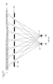
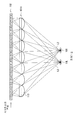
도 33은, 복수의 시차 화상으로부터 합성 화상이 생성되기까지의 과정을 모식적으로 도시하고 있다. 도 33에서는, 제1 내지 제4의 4개의 시차 화상을 이용한 예를 도시하고 있다. 도 33의 상단에 도시한 바와 같은 제1 내지 제4의 시차 화상은 도 33의 중단에 도시한 바와 같이, 각각 스트라이프 형상의 분할 화상으로 분할된다. 이러한 분할 화상을, 각 시차 화상마다 수평 방향으로 교대로 배열함으로써, 도 33의 하단에 도시한 바와 같은 합성 화상을 생성한다. 결과적으로, 합성 화상은, 제1 내지 제4의 시차 화상으로부터 각각 분할된 스트라이프 형상의 분할 화상이, 제1, 제2, 제3 및 제4의 시차 화상의 순서로 수평 방향으로 교대로 순환적으로 배열된 합성 화상이 된다.33 schematically illustrates a process from generation of a plurality of parallax images to generation of a synthesized image. In FIG. 33, the example which used the 4th to 4th parallax image is shown. As shown in the middle of FIG. 33, the first to fourth parallax images as shown in the upper part of FIG. 33 are divided into stripe-shaped divided images, respectively. By arranging such divided images alternately in the horizontal direction for each parallax image, a synthesized image as shown at the bottom of FIG. 33 is generated. As a result, in the composite image, stripe-shaped divided images divided from the first to fourth parallax images are cyclically alternated in the horizontal direction in the order of the first, second, third and fourth parallax images. A composite image is arranged.
도 32에서는, 도 33에 도시한 합성 화상을 2차원 표시 패널(102)에 표시함으로써, 다안식의 입체표시를 하고 있는 상태를 나타내고 있다. 2차원 표시 패널(102)에 표시된 합성 화상을, 패럴랙스 배리어(101)를 통하여 관찰함으로써, 어느 특정한 시점에서 본 때에, 좌안(10L)과 우안(10R)에, 어느 특정한 시차 화상만이 보이는 상황으로 됨으로써 입체상이 지각된다. 도 32에서는, 좌안(10L)에는 제3의 시차 화상으로부터의 광(L3)만이 인식되고, 우안(10R)에는 제2의 시차 화상으로부터의 광(L2)만이 인식된 상황으로 됨으로써, 제3의 시차 화상과 제2의 시차 화상에 의거한 입체상이 지각되고 있다.In FIG. 32, the composite image shown in FIG. 33 is displayed on the
도 34 및 도 35는, 렌티큘러 방식에 의한 입체 화상 표시 장치의 일반적인 구성례를 도시하고 있다. 이 입체 화상 표시 장치는, 도 31 및 도 32에 도시한 패럴랙스 배리어 방식에 의한 입체 화상 표시 장치에 대해, 시차 분리 구조로서, 패럴랙스 배리어(101)에 대신하여 렌티큘러 렌즈(101A)를 2차원 표시 패널(102)의 표시면측에 대향 배치한 것이다.34 and 35 show a general configuration example of a three-dimensional image display device by a lenticular method. This three-dimensional image display device uses a parallax separation structure as a parallax separation structure for the three-dimensional image display device according to the parallax barrier system shown in FIGS. 31 and 32 to two-dimensional the
렌티큘러 렌즈(101A)는, 예를 들면 수직 방향으로 연재되고, 수평 방향으로만 굴절력을 갖는 실린드리컬 렌즈(분할 렌즈)(113)을, 수평 방향으로 다수 병렬 배치한 것이다. 실린드리컬 렌즈(113)의 렌즈 피치는, 표시하는 시차수에 응하여 적절하게 설정되어 있다. 예를 들면 4시차로의 다안시를 행하는 경우, 하나의 실린드리컬 렌즈(113)에 대해 시차가 다른 4개의 분할 화상이 대응하도록 설정되어 있다. 이와 같이 설정함으로써, 2차원 표시 패널(102)로부터의 표시 화상광을, 각 시차 화상마다 다른 방향으로 편향하여 출사시킨다.The
도 35에서는, 이 입체 화상 표시 장치에서, 도 33에 도시한 합성 화상을 2차원 표시 패널(102)에 표시함으로써, 다안식의 입체표시를 하고 있는 상태를 나타내고 있다. 2차원 표시 패널(102)에 표시된 합성 화상을, 렌티큘러 렌즈(101A)를 통하여 관찰함으로써, 어느 특정한 시점에서 본 때에, 좌안(10L)과 우안(10R)에, 어느 특정한 시차 화상만이 보이는 상황으로 됨으로써 입체상이 지각된다. 도 35에서는, 좌안(10L)에는 제3의 시차 화상으로부터의 광(L3)만이 인식되고, 우안(10R)에는 제2의 시차 화상으로부터의 광(L2)만이 인식되는 상황으로 됨으로써, 제3의 시차 화상과 제2의 시차 화상에 의거한 입체상이 지각되어 있다.In this stereoscopic image display apparatus, the composite image shown in FIG. 33 is displayed on the
상기한 바와 같은 패럴랙스 배리어 방식이나 렌티큘러 방식 등의 입체 화상 표시 장치에서는, 관찰자의 좌우의 눈에, 다른 시차 화상으로부터의 광을 입사시킴으로써, 입체시를 실현하고 있다. 이 때문에, 양호한 입체시를 실현하기 위해서는, 표시 패널의 각 화소와 패럴랙스 배리어의 슬릿부 등과의 상대 위치를 설계치에 정확하게 맞출 필요가 있고, 어떠한 요인으로 그 위치에 어긋남이 생기면, 입체시의 품질에 열화가 발생하는 문제가 있다.In the stereoscopic image display apparatuses such as the parallax barrier system and the lenticular system as described above, stereoscopic vision is realized by injecting light from another parallax image into the left and right eyes of the observer. For this reason, in order to realize good stereoscopic vision, it is necessary to accurately match the relative position of each pixel of the display panel with the slit portion of the parallax barrier and the like according to the design value. There is a problem that deterioration occurs.
일본국 특개2004-179806호 공보에는, CRT(음극선관)와 패럴랙스 배리어를 조합시킨 입체 화상 표시 장치에서, 패럴랙스 배리어의 위치 어긋남을, CRT의 주사 위치 등의 조정을 행함으로써 보정하고 있다. 상기 일본국 특개2004-179806호 공보에 기재된 기술에서는, CRT의 주사 위치의 시작 위치나 주사선의 폭의 조정을 행함으로써, 패럴랙스 배리어의 위치 어긋남의 보정을 행하고 있지만, 화소 단위로 위치 어긋남이 발생하는 경우에는 대응할 수가 없다.Japanese Laid-Open Patent Publication No. 2004-179806 corrects the positional shift of the parallax barrier by adjusting the scanning position of the CRT and the like in a three-dimensional image display device combining a CRT (cathode ray tube) and a parallax barrier. In the technique described in Japanese Patent Laid-Open No. 2004-179806, the positional shift of the parallax barrier is corrected by adjusting the start position of the scanning position of the CRT and the width of the scanning line, but the positional shift occurs in units of pixels. If you do not respond.
본 발명은 이러한 문제점을 감안하여 이루어진 것으로, 그 목적은, 시차 어긋남을 억제한 양호한 입체 화상 표시를 행할 수 있도록 한 화상 처리 장치, 입체 화상 표시 장치 및 입체 화상 표시 시스템, 및 입체 화상 표시 장치의 시차 어긋남 검출 방법 및 입체 화상 표시 장치의 제조 방법을 제공하는 것에 있다.The present invention has been made in view of the above problems, and an object thereof is to provide a parallax between an image processing device, a stereoscopic image display device and a stereoscopic image display system, and a stereoscopic image display device capable of performing satisfactory stereoscopic image display with suppressed parallax deviation. It is providing the deviation detection method and the manufacturing method of a three-dimensional image display apparatus.
본 발명에 의한 화상 처리 장치는, 입체 화상 표시 장치에서 생긴 시차 어긋남에 관한 시차 어긋남 데이터를 기억하는 기억부와, 시차 어긋남 데이터에 의거하여, 입체 화상 표시 장치에 표시되는 입체 화상을 보정하는 시차 어긋남 보정부를 구비한 것이다. 여기서의 입체 화상 표시 장치는, 복수의 화소가 2차원적으로 배열되고, 복수의 시차 화상을 합성한 시차 합성 화상을 표시하는 표시부와, 시차 합성 화상에 포함되는 복수의 시차 화상을 분리하는 시차 분리 구조를 포함하는 것이다.The image processing apparatus according to the present invention includes a storage unit that stores parallax shift data relating to parallax shifts generated in a stereoscopic image display device, and a parallax shift that corrects a stereoscopic image displayed on the stereoscopic image display device based on the parallax shift data. The correction part is provided. The three-dimensional image display device here includes a display unit for displaying a parallax synthesized image in which a plurality of pixels are arranged two-dimensionally and combining a plurality of parallax images, and parallax separation for separating a plurality of parallax images included in the parallax synthesized image. It includes the structure.
본 발명에 의한 입체 화상 표시 장치는, 복수의 화소가 2차원적으로 배열되고, 복수의 시차 화상을 합성한 시차 합성 화상을 표시하는 표시부와, 복수의 화소의 각각에 대응지어지고, 시차 합성 화상에 포함되는 복수의 시차 화상을 분리하는 시차 분리 부품과, 시차 어긋남 데이터에 의거하여 시차 합성 화상을 보정하는 시차 어긋남 보정부를 구비한 것이다.In the three-dimensional image display device according to the present invention, a plurality of pixels are two-dimensionally arranged, a display unit for displaying a parallax composite image obtained by synthesizing a plurality of parallax images, and a parallax composite image, respectively. It is provided with the parallax separation component which isolate | separates the some parallax image contained in the, and the parallax deviation correction part which correct | amends a parallax difference image based on parallax deviation data.
본 발명에 의한 입체 화상 표시 시스템은, 입체 화상 표시 장치와, 입체 화상 표시 장치에서 생긴 시차 어긋남을 검출하고, 시차 어긋남에 관한 시차 어긋남 데이터를 생성하는 시차 어긋남 해석 수단과, 시차 어긋남 데이터를 기억하는 기억부와, 시차 어긋남 데이터에 의거하여, 입체 화상 표시 장치에 표시되는 입체 화상을 보정하는 시차 어긋남 보정부를 구비한 것이다. 여기서의 입체 화상 표시 장치는, 복수의 화소가 2차원적으로 배열되고, 복수의 시차 화상을 합성한 시차 합성 화상을 표시하는 표시부와, 시차 합성 화상에 포함되는 복수의 시차 화상을 분리하는 시차 분리 구조를 포함하는 것이다.The stereoscopic image display system according to the present invention detects parallax deviations generated in a stereoscopic image display device, a stereoscopic image display device, stores parallax deviation analysis means for generating parallax deviation data relating to parallax deviation, and stores parallax deviation data. A storage unit and a parallax shift correction unit for correcting a stereoscopic image displayed on the stereoscopic image display device based on the parallax shift data. The three-dimensional image display device here includes a display unit for displaying a parallax synthesized image in which a plurality of pixels are arranged two-dimensionally and combining a plurality of parallax images, and parallax separation for separating a plurality of parallax images included in the parallax synthesized image. It includes the structure.
본 발명의 화상 처리 장치, 입체 화상 표시 장치 또는 입체 화상 표시 시스템에서는, 시차 어긋남에 관한 시차 어긋남 데이터에 의거하여, 시차 어긋남 보정부에 의해 시차 합성 화상이 보정된다.In the image processing apparatus, the three-dimensional image display device, or the three-dimensional image display system of the present invention, the parallax shift correction unit corrects the parallax shift image based on the parallax shift data regarding the parallax shift.
예를 들면, 시차 어긋남 보정부는, 특정한 시점에서 관측한 때에 특정한 시차 화상 이외의 다른 시차 화상이 관찰되는 시차 어긋남이 생기는 상태가 된 경우에, 특정한 시점에서 관찰되는 다른 시차 화상의 비율을 감소시키도록, 복수의 시차 화상의 각각을 표시하는 화소 위치의 이동을 행한다.For example, the parallax misalignment correction unit reduces the ratio of other parallax images observed at a specific time point when a parallax shift occurs in which a parallax shift is observed when other parallax images other than the specific parallax image are observed when observed at a specific time point. Then, the pixel position for displaying each of the plurality of parallax images is moved.
보다 구체적으로는, 시차 어긋남 보정부는 예를 들면, 시차 어긋남의 값이 1화소의 정수배에 상당하는 경우에는, 시차 어긋남의 값에 응하여 다른 시차 화상과 특정한 시차 화상을 표시하는 화소 위치의 이동을 행하고, 시차 어긋남의 값이 1화소 미만의 값을 포함하는 경우에는, 시차 어긋남의 값에 응하여 다른 시차 화상의 화소치와 특정한 시차 화상의 화소치를 합성하는 보정을 행한다.More specifically, the parallax misalignment correction unit, for example, when the value of the parallax misalignment corresponds to an integer multiple of one pixel, moves the pixel position displaying a different parallax image and a specific parallax image in response to the parallax misalignment value. When the value of parallax shift contains less than 1 pixel, correction is performed to synthesize pixel values of another parallax image and pixel values of a specific parallax image in response to the value of parallax shift.
본 발명에 의한 입체 화상 표시 장치의 시차 어긋남 검출 방법은, 서브 픽셀 단위로 복수의 화소가 2차원적으로 배열되고, 복수의 시차 화상을 합성한 시차 합성 화상을 표시하는 표시부와, 시차 합성 화상에 포함되는 복수의 시차 화상을 분리하는 시차 분리 구조를 포함하는 입체 화상 표시 장치에서의 시차 어긋남의 검출 방법으로서, 특정한 시점에 대응하는 서브 픽셀과 다른 시점에 대응하는 다른 서브 픽셀을 특정한 계측용 패턴 화상을 형성하기 위해 발광시키고, 특정한 시점에서 입체 화상 표시 장치를 촬영하는 스텝과, 촬영된 특정한 계측용 패턴 화상을 해석함으로써 시차 어긋남을 검출하는 스텝을 포함하는 것이다.A parallax shift detection method of a three-dimensional image display device according to the present invention includes a display unit for displaying a parallax synthesized image in which a plurality of pixels are two-dimensionally arranged in sub-pixel units and combining a plurality of parallax images, and a parallax synthesized image. A method for detecting parallax deviation in a stereoscopic image display device including a parallax separation structure for separating a plurality of parallax images included, the measurement pattern image specifying a subpixel corresponding to a specific viewpoint and another subpixel corresponding to a different viewpoint Emitting light to form light, and detecting the parallax deviation by analyzing the stereoscopic image display device at a specific time point and analyzing the photographed specific measurement pattern image.
본 발명에 의한 입체 화상 표시 장치의 제조 방법은, 서브 픽셀 단위로 복수의 화소가 2차원적으로 배열되고, 복수의 시차 화상을 합성한 시차 합성 화상을 표시하는 표시부와, 시차 합성 화상에 포함되는 복수의 시차 화상을 분리하는 시차 분리 구조와, 시차 어긋남에 관한 시차 어긋남 데이터를 기억하는 기억부와, 시차 어긋남 데이터에 의거하여 시차 합성 화상을 보정하는 시차 어긋남 보정부를 포함하는 입체 화상 표시 장치의 제조 방법으로서, 특정한 시점에 대응하는 서브 픽셀과 다른 시점에 대응하는 다른 서브 픽셀을 특정한 계측용 패턴 화상을 형성하기 위해 발광시키고, 특정한 시점에서 입체 화상 표시 장치를 촬영하는 촬영 공정과, 촬영된 특정한 계측용 패턴 화상을 해석함으로써 시차 어긋남을 검출하는 공정과, 검출된 시차 어긋남에 관한 시차 어긋남 데이터를 기억부에 기억시키는 기억 공정을 갖는 것이다.A manufacturing method of a three-dimensional image display device according to the present invention includes a display unit that displays a parallax synthesized image in which a plurality of pixels are arranged two-dimensionally in subpixel units, and synthesizes a plurality of parallax images, and a parallax synthesized image. Manufacture of a stereoscopic image display device including a parallax separation structure for separating a plurality of parallax images, a storage unit for storing parallax shift data regarding parallax shifts, and a parallax shift correction unit for correcting parallax shifted images based on parallax shift data As a method, a photographing process of causing a subpixel corresponding to a specific viewpoint and another subpixel corresponding to a different viewpoint to emit light to form a specific measurement pattern image, and photographing a stereoscopic image display device at a specific viewpoint; The step of detecting the parallax deviation by analyzing the pattern image for It has a memory | storage process which stores a parallax shift | offset data concerning a memory | storage part.
본 발명의 화상 처리 장치, 입체 화상 표시 장치 또는 입체 화상 표시 시스템에 의하면, 시차 어긋남 데이터에 의거하여 시차 합성 화상을 보정하도록 하였기 때문에, 화면 전체에 걸쳐서 시차 어긋남을 억제한 양호한 입체 화상 표시를 행할 수 있다.According to the image processing apparatus, the stereoscopic image display apparatus or the stereoscopic image display system of the present invention, since the parallax composite image is corrected based on the parallax deviation data, it is possible to perform satisfactory stereoscopic image display with suppressed parallax deviation over the entire screen. have.
본 발명의 입체 화상 표시 장치의 시차 어긋남 검출 방법 또는 입체 화상 표시 장치의 제조 방법에 의하면, 특정한 시점에 대응하는 서브 픽셀과 다른 시점에 대응하는 다른 서브 픽셀을 특정한 계측용 패턴 화상을 형성하기 위해 발광시키고, 특정한 시점에서 입체 화상 표시 장치를 촬영하고, 그 촬영된 특정한 계측용 패턴 화상을 해석함으로써 시차 어긋남을 검출하도록 하였기 때문에, 시차 어긋남에 관한 시차 어긋남 데이터를 서브 픽셀 마다 구할 수 있다. 이에 의거하여, 화면 전체에 걸쳐서 시차 어긋남을 억제한 양호한 입체 화상 표시를 행할 수 있다.According to the parallax shift detection method of the stereoscopic image display apparatus or the manufacturing method of the stereoscopic image display apparatus of the present invention, light is emitted to form a measurement pattern image for specifying a subpixel corresponding to a specific viewpoint and another subpixel corresponding to a different viewpoint. Since the parallax deviation is detected by capturing the stereoscopic image display device at a specific viewpoint and analyzing the photographed specific measurement pattern image, parallax deviation data relating to parallax deviation can be obtained for each subpixel. Based on this, favorable stereoscopic image display which suppressed parallax deviation can be performed over the whole screen.
도 1은 본 발명의 제1의 실시예에 관한 입체 화상 표시 시스템의 한 구성례를 도시하는 블록도.
도 2는 표시 패널의 화소 배열의 한 예를 도시하는 평면도.
도 3은 도 1에 도시한 입체 화상 표시 시스템에서, 시차 어긋남 검출시의 카메라에 의한 촬영에 관한 설명도.
도 4(A)는 도 1에 도시한 입체 화상 표시 시스템에서의 시차 어긋남 검출 처리를 도시하는 흐름도. 도 4(B)는 도 1에 도시한 입체 화상 표시 시스템에서의 시차 어긋남 데이터를 이용한 입체 화상 표시의 처리를 도시하는 흐름도.
도 5는 시차 어긋남 검출 처리의 개요를 도시하는 설명도.
도 6은 시차 어긋남 계측용의 계측용 패턴 화상의 한 예를 도시하는 설명도.
도 7은 패럴랙스 배리어의 배리어 패턴의 한 예를 도시하는 평면도.
도 8은 도 6에 도시한 계측용 패턴 화상과 도 7에 도시한 패럴랙스 배리어와의 조합을 모식적으로 도시하는 설명도.
도 9는 도 6에 도시한 계측용 패턴 화상을 도 7에 도시한 패럴랙스 배리어를 통하여 관찰한 상태의 한 예를 모식적으로 도시하는 설명도.
도 10은 패럴랙스 배리어에 위치 어긋남이 있는 경우의 배리어 패턴의 한 예를 도시하는 설명도.
도 11은 도 6에 도시한 계측용 패턴 화상과 도 10에 도시한 패럴랙스 배리어와의 조합을 모식적으로 도시하는 설명도.
도 12는 도 6에 도시한 계측용 패턴 화상을 도 10에 도시한 패럴랙스 배리어를 통하여 관찰한 상태의 한 예를 모식적으로 도시하는 설명도.
도 13은 데이터의 솎아냄에 관한 설명도.
도 14는 시점수가 5개인 경우의 패럴랙스 배리어의 배리어 패턴의 한 예를 도시하는 평면도.
도 15는 5시점에서의 입체표시를 행하는 경우에 있어서, 도 6에 도시한 계측용 패턴 화상을 도 14의 패럴랙스 배리어를 통하여 제2 시점에서 관찰한 상태의 한 예를 모식적으로 도시하는 단면도.
도 16은 5시점에서의 입체표시를 행하는 경우에 있어서, 도 6에 도시한 계측용 패턴 화상을 도 14의 패럴랙스 배리어를 통하여 제2 시점에서 관찰한 상태의 한 예를 모식적으로 도시하는 평면도.
도 17은 시점수가 5개인 경우에 적합한 계측용 패턴 화상의 한 예를 도시하는 설명도.
도 18은 도 17에 도시한 계측용 패턴 화상을 도 14의 패럴랙스 배리어를 통하여 제3 시점에서 관찰한 상태의 한 예를 모식적으로 도시하는 설명도.
도 19는 시점수가 5개인 경우의 각 서브 픽셀과 각 시점와의 대응 관계를 도시하는 설명도.
도 20은 시차 어긋남이 적은 상태에서, 시분할로 시점 마다의 계측용 패턴 화상을 표시한 경우에 제2 시점에서 관측되는 휘도 분포의 한 예를 도시하는 설명도.
도 21은 시차 어긋남이 큰 상태에서, 시분할로 시점 마다의 계측용 패턴 화상을 표시한 경우에 제2 시점에서 관측되는 휘도 분포의 한 예를 도시하는 설명도.
도 22는 시차 합성 화상의 보정에 관한 설명도.
도 23(A)는 시차 어긋남이 없는 상태를 도시하는 설명도, 도 23(B)는 시차 어긋남이 있는 상태를 도시하는 설명도.
도 24는 시차 어긋남량의 산출 방법의 한 예를 도시하는 설명도.
도 25는 시차 어긋남이 없는 상태에서의 서브 픽셀과 슬릿부와의 관계를 도시하는 설명도.
도 26(A)는 도 25에 대해 1서브 픽셀에 상당하는 시차 어긋남이 있는 상태를 모식적으로 도시하는 설명도. 도 26(B)는 도 26(A)의 시차 어긋남에 대응하는 화상 보정의 수법의 한 예를 도시하는 설명도. 도 26(C)는 도 26(A)에 대해 화상 보정을 행한 후의 상태를 도시하는 설명도.
도 27(A)는 도 25에 대해 서브 픽셀의 정수배가 아닌 시차 어긋남이 있는 상태를 모식적으로 도시하는 설명도. 도 27(B)는 도 27(B)의 시차 어긋남에 대응하는 화상 보정의 수법의 한 예를 도시하는 설명도. 도 27(C)는 도 27(B)에 대해 화상 보정을 행한 후의 상태를 도시하는 설명도.
도 28은 본 발명의 제4의 실시예에 관한 입체 화상 표시 시스템의 한 구성례를 도시하는 블록도.
도 29는 패럴랙스 배리어의 배리어 패턴의 제1의 변형례를 도시하는 설명도.
도 30은 패럴랙스 배리어의 배리어 패턴의 제2의 변형례를 도시하는 설명도.
도 31은 일반적인 패럴랙스 배리어 방식에 의한 입체표시의 개념을 도시하는 설명도.
도 32는 일반적인 패럴랙스 배리어 방식에 의한 입체표시의 개념을 도시하는 설명도.
도 33은 시차 화상의 합성에 관한 설명도.
도 34는 일반적인 렌티큘러 방식에 의한 입체표시의 개념을 도시하는 설명도.
도 35는 일반적인 렌티큘러 방식에 의한 입체표시의 개념을 도시하는 설명도.1 is a block diagram showing a configuration example of a stereoscopic image display system according to a first embodiment of the present invention.
2 is a plan view illustrating an example of a pixel array of a display panel;
3 is an explanatory diagram of photographing by a camera at the time of parallax deviation detection in the three-dimensional image display system shown in FIG.
FIG. 4A is a flowchart showing the parallax shift detection processing in the stereoscopic image display system shown in FIG. FIG. 4B is a flowchart showing a process of stereoscopic image display using parallax deviation data in the stereoscopic image display system shown in FIG. 1; FIG.
5 is an explanatory diagram showing an outline of a parallax shift detection process;
6 is an explanatory diagram showing an example of a pattern image for measurement for parallax deviation measurement.
7 is a plan view illustrating an example of a barrier pattern of a parallax barrier.
FIG. 8 is an explanatory diagram schematically showing a combination of the measurement pattern image shown in FIG. 6 and the parallax barrier shown in FIG. 7.
FIG. 9 is an explanatory diagram schematically showing an example of a state in which the measurement pattern image shown in FIG. 6 is observed through the parallax barrier shown in FIG. 7. FIG.
10 is an explanatory diagram showing an example of a barrier pattern when there is a positional shift in the parallax barrier.
FIG. 11 is an explanatory diagram schematically showing a combination of the measurement pattern image shown in FIG. 6 and the parallax barrier shown in FIG. 10.
FIG. 12 is an explanatory diagram schematically showing an example of a state where the measurement pattern image shown in FIG. 6 is observed through the parallax barrier shown in FIG. 10.
Fig. 13 is an explanatory diagram concerning the removal of data;
14 is a plan view illustrating an example of a barrier pattern of a parallax barrier when there are five viewpoints.
15 is a cross-sectional view schematically showing an example of a state in which the measurement pattern image shown in FIG. 6 is observed at a second viewpoint through the parallax barrier of FIG. 14 when stereoscopic display is performed at five views. .
16 is a plan view schematically showing an example of a state in which the measurement pattern image shown in FIG. 6 is observed at a second viewpoint through the parallax barrier of FIG. 14 when stereoscopic display is performed at five points in time. .
17 is an explanatory diagram showing an example of a measurement pattern image suitable for a case where five viewpoints are used;
18 is an explanatory diagram schematically showing an example of a state in which the measurement pattern image shown in FIG. 17 is observed at a third viewpoint through the parallax barrier of FIG. 14.
Fig. 19 is an explanatory diagram showing a correspondence relationship between each sub-pixel and each viewpoint when the number of viewpoints is five;
20 is an explanatory diagram showing an example of a luminance distribution observed at a second viewpoint when displaying the measurement pattern image for each viewpoint by time division in a state where there is little parallax deviation;
FIG. 21 is an explanatory diagram showing an example of a luminance distribution observed at a second viewpoint when displaying the measurement pattern image for each viewpoint by time division in a state where large parallax deviation is present; FIG.
Fig. 22 is an explanatory diagram concerning the correction of a parallax composite image.
FIG. 23A is an explanatory diagram showing a state without parallax deviation, and FIG. 23B is an explanatory diagram showing a state with parallax deviation.
24 is an explanatory diagram illustrating an example of a method for calculating the amount of parallax deviation.
25 is an explanatory diagram showing a relationship between a subpixel and a slit portion in a state where there is no parallax shift;
FIG. 26A is an explanatory diagram schematically showing a state where there is a parallax shift corresponding to one sub pixel with respect to FIG. 25. FIG. FIG. 26B is an explanatory diagram showing an example of a method of image correction corresponding to the parallax deviation of FIG. 26A. FIG. FIG. 26C is an explanatory diagram showing a state after image correction is performed with respect to FIG. 26A. FIG.
FIG. 27 (A) is an explanatory diagram schematically showing a state where there is a parallax shift, not an integer multiple of a subpixel, in FIG. 25. FIG. FIG. 27B is an explanatory diagram showing an example of a method of image correction corresponding to the parallax deviation of FIG. 27B. FIG. FIG. 27C is an explanatory diagram showing a state after image correction is performed with respect to FIG. 27B. FIG.
Fig. 28 is a block diagram showing a configuration example of a stereoscopic image display system according to a fourth embodiment of the present invention.
29 is an explanatory diagram showing a first modification of the barrier pattern of the parallax barrier.
30 is an explanatory diagram showing a second modification of the barrier pattern of the parallax barrier.
Fig. 31 is an explanatory diagram showing the concept of stereoscopic display by a general parallax barrier method.
Fig. 32 is an explanatory diagram showing the concept of stereoscopic display by a general parallax barrier method.
33 is an explanatory diagram of synthesizing a parallax image.
Explanatory drawing which shows the concept of three-dimensional display by a general lenticular system.
Explanatory drawing which shows the concept of three-dimensional display by a general lenticular system.
이하, 본 발명의 실시예에 관해 도면을 참조하여 상세히 설명한다.Hereinafter, embodiments of the present invention will be described in detail with reference to the drawings.
(제1의 실시예)(First Embodiment)
[입체 화상 표시 시스템의 구성][Configuration of Stereoscopic Image Display System]
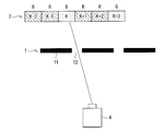
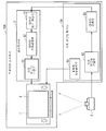
도 1은, 본 발명의 제1의 실시예에 관한 입체 화상 표시 시스템의 한 구성례를 도시하고 있다. 이 입체 화상 표시 시스템은, 카메라(4)와, 시차 어긋남 해석부(5)와, 입체 화상 표시 장치(10)를 구비하고 있다. 시차 어긋남 해석부(5)는, 계측용 화상 출력부(51)와, 시차 어긋남 검출부(52)와, 데이터 압축부(53)를 갖고 있다. 입체 화상 표시 장치(10)는, 패럴랙스 배리어(1) 및 표시 패널(2)과, 화상 처리부(3)를 갖고 있다. 화상 처리부(3)는, 데이터 보존 메모리(31)와, 데이터 압축 해제부(32)와, 시차 어긋남 보정부(33)를 갖고 있다. 패럴랙스 배리어(1)는, 예를 들면 도 3 및 도 7에 도시한 바와 같이, 차폐부(11)와, 슬릿부(12)를 갖고 있다.1 shows an example of the configuration of a three-dimensional image display system according to a first embodiment of the present invention. This stereoscopic image display system is provided with the
패럴랙스 배리어(1)는, 본 발명에서의 "시차 분리 구조"의 하나의 구체예에 대응하고 있다. 표시 패널(2)은, 본 발명에서의 "표시부"의 하나의 구체예에 대응하고 있다. 데이터 보존 메모리(31)는, 본 발명에서의 "기억부"의 하나의 구체예에 대응하고 있다. 시차 어긋남 보정부(33)는, 본 발명에서의 "시차 어긋남 보정부"의 하나의 구체예에 대응하고 있다. 카메라(4)와 시차 어긋남 해석부(5)는, 본 발명에서의 "시차 어긋남 해석 수단"의 하나의 구체예에 대응하고 있다. 카메라(4)는, 본 발명에서의 "촬영부"의 하나의 구체예에 대응하고 있다.The
표시 패널(2)은, 액정 표시 패널, 일렉트릭 루미넌스 방식의 표시 패널, 또는 플라즈마 디스플레이 등의 2차원 표시 디스플레이로 구성되어 있다. 표시 패널(2)의 표시 화면에는, 복수의 화소가 2차원적으로 배열되어 있다. 표시 패널(2)의 표시 화면에는, 예를 들면 도 2에 도시한 바와 같이, 복수의 화소로서, 복수색의 서브 픽셀이 주기적으로 2차원적으로 배열되어 있다. 도 2에서는, 수평 방향으로 R(적색)의 서브 픽셀과, G(녹색)의 서브 픽셀과, B(청색)의 서브 픽셀이 교대로 배열되고, 수직 방향으로는 동일색의 서브 픽셀이 배열된 예를 도시하고 있다. 표시 패널(2)에는, 복수의 시차 화상을 합성한 시차 합성 화상이 표시되도록 되어 있다.The
패럴랙스 배리어(1)는, 표시 패널(2)에 표시된 시차 합성 화상에 포함되는 복수의 시차 화상을 입체시가 가능하게 되도록 분리하는 것이고, 입체시를 가능하게 하도록 표시 패널(2)에 대해 소정의 위치 관계로 대향 배치되어 있다. 패럴랙스 배리어(1)는, 예를 들면 도 3 및 도 7에 도시한 바와 같이, 광을 차폐하는 차폐부(11)와, 광을 투과하고, 표시 패널(2)의 화소에 대해 입체시가 가능하게 되도록 대응지어진 시차 분리 부품으로서의 슬릿부(12)를 갖고 있다. 패럴랙스 배리어(1)는, 예를 들면 투명한 평면판의 위에, 차폐부(11)로서, 광을 통과시키지 않는 흑색의 물질이나, 광을 반사하는 박막형상의 금속 등을 설치함으로써 형성되어 있다.The
패럴랙스 배리어(1)는, 이상적인 상태에서는, 특정한 시점에서 표시 패널(2)을 관측한 때에 특정한 시차 화상만이 관찰되도록, 표시 패널(2)의 화면상의 시차 합성 화상에 포함되는 복수의 시차 화상을 분리하도록 되어 있다. 패럴랙스 배리어(1)의 슬릿부(12)와, 표시 패널(2)의 각 화소와의 위치 관계로부터, 표시 패널(2)의 각 화소에서 발하여진 광의 출사 각도가 제한된다. 표시 패널(2)에서의 각 화소는, 슬릿부(12)와의 위치 관계에 의해, 표시되는 방향이 다르게 된다. 관찰자는, 좌우의 눈에서 다른 영상을 관찰하는 상태가 됨으로써 입체 영상으로서 지각할 수 있다. 각 화소는 표시되는 방향이 다르기 때문에, 표시 패널(2)에서, 표시되는 각도에 대응한 시차 화상을 표시함으로써 입체시가 가능하게 된다.In the ideal state, the
또한, 이 입체 화상 표시 장치(10)에서의 입체표시(입체시)의 기본 원리는, 종래 기술의 일반적인 패럴랙스 배리어 방식에 의한 입체 화상 표시 장치(도 31 및 도 32 참조)와 마찬가지이다. 도 31의 패럴랙스 배리어(101)에서는 수직 방향으로 연재되는 슬릿부(112)를 설치한 예를 도시하고, 도 7에서는 경사 방향으로 스텝 형상으로 슬릿부(12)를 마련한 예를 도시하고 있지만, 슬릿부(12)의 설치 패턴(배리어 패턴)이 다를 뿐으로, 시차 분리를 행하는 기능 자체는 배리어 패턴의 차이에 관계없이 마찬가지이다. 표시 패널(2)에 표시되는 시차 합성 화상은, 배리어 패턴에 응한 패턴으로 복수의 시차 화상이 합성된 것이 된다. 도 33에 도시한 합성 화상은, 수직 방향으로 연재되는 배리어 패턴에 대응한 예이다. 도 7에 도시한 바와 같은 스텝 형상의 배리어 패턴인 경우에는, 복수의 시차 화상을, 그 배리어 패턴에 응하여 경사 방향으로 단차 형상으로 분할하여 합성한다.In addition, the basic principle of stereoscopic display (stereoscopic) in the stereoscopic
여기서는, 표시 패널(2)의 화면에 표시된 시차 화상, 패럴랙스 배리어(1)의 슬릿부(12) 등, 및 양쪽 눈의 상대적인 위치 관계가, 양호한 입체시를 실현하기 위해 중요해진다. 특히 횡방향의 위치 어긋남은, 입체시를 실현하고 있는 시차 화상에 대해 영향이 크기 때문에, 중요하다. 그러나, 실제의 입체 화상 표시 장치(10)에서는, 표시 패널(2)의 화면이 국소적으로 면내에서 늘어나거나 줄어들거나 한다. 또한, 면과 수직한 방향으로 휘거나(변형되거나) 한다. 또한 패럴랙스 배리어(1)에 관해서 도, 마찬가지로, 국소적으로 면내에서 늘어나거나 줄어들거나, 또한 면과 수직한 방향으로 휘거나(변형되거나) 한다. 또한, 표시 패널(2)의 화면과 패럴랙스 배리어(1)와의 거리에 관해서도, 정확한 설계 위치로 완전히 조정되지 않는 경우가 있다. 또한, 실제의 입체 화상 표시 장치의 제조시에는 다양한 편차가 생긴다.Here, the relative positional relationship between the parallax image displayed on the screen of the
이와 같은 경우에, 표시 패널(2)의 각 화소와 패럴랙스 배리어(1)의 슬릿부(12)와의 상대적인 위치 관계가, 정확한 설계치에 일치하지 않게 되는 문제가 생긴다. 그 결과로서, 특히 횡방향의 위치 관계에 어긋남이 있는 경우에는, 관찰자의 눈에 대해 시차 화상이 정상적으로 입사되지 않고, 입체시의 품질에 열화가 발생하는 문제가 있다. 이 때문에, 본 실시예에서는, 예를 들면, 입체 화상 표시 장치(10)의 제조시의 장치 조립에 있어서, 표시 패널(2)의 화면의 서브 픽셀과 패럴랙스 배리어(1)의 슬릿부(12)와의 상대적인 위치 관계에, 조립 오차, 편차 등에 의해 어긋남이 발생한 경우에 시차 어긋남의 보상을 행하도록 되어 있다. 본 실시예에 의하면, 예를 들면 액정 디스플레이 등의 최근의 고정밀한 표시 패널(2)과 패럴랙스 배리어(1)를 조합시킨 입체 화상 표시 장치(10)에서, 화소 단위로의 세밀한 위치 어긋남 보정을 하는 것이 가능하다.In such a case, there arises a problem that the relative positional relationship between each pixel of the
예를 들면, 카메라(4)는 도 3에 도시한 바와 같이, 특정한 계측용 패턴 화상을 표시 패널(2)에 표시한 상태에서, 특정한 시점에서 입체 화상 표시 장치(10)(패럴랙스 배리어(1) 및 표시 패널(2))을 촬영하는 것이다. 계측용 화상 출력부(51)는, 예를 들면 후술하는 도 6에 도시하는 바와 같은, 복수의 시차 화상이 서브 픽셀 단위로 주기적으로 표시되는 특정한 계측용 패턴 화상을 표시 패널(2)에 표시하는 것이다. 또한, 도 3에서, 표시 패널(2)의 부분에 붙인 번호 1, 2, 3, 4, 5, 6은, 제1 내지 제6의 시점에 대응하는 시차 화상의 번호(시점 번호)를 나타내고 있다. 즉, 도 3에서는, 6시차분의 시차 화상을, 도 6에 도시하는 바와 같은 R, G, B의 서브 픽셀 단위로 주기적으로 표시하고 있다. 또한, 도 3에서는, 패럴랙스 배리어(1)를 통하여, 2번째의 시차 화상이 특정한 시점 화상으로서 관찰되는 특정한 시점(여기서는 제2 시점)로부터 입체 화상 표시 장치(10)를 촬영하고 있는 예를 도시하고 있다. 패럴랙스 배리어(1)는, 이상적인 상태에서는, 특정한 시점에서 관측한 때에 특정한 시차 화상만이 관찰되도록 시차 합성 화상에 포함되는 복수의 시차 화상을 분리한다. 따라서, 특정한 시점에서 관측한 때에 특정한 시차 화상 이외의 다른 시차 화상이 관찰되는 경우에는, 그것이 시차 어긋남으로서 관측된다. 도 3의 예에서는, 2번째의 시차 화상 이외의 다른 시차 화상이 관측된 경우에는, 시차 어긋남이 생기게 된다.For example, as shown in Fig. 3, the
시차 어긋남 해석부(5)는, PC(퍼스널 컴퓨터) 등의 컴퓨터 장치로 구성할 수 있다. 시차 어긋남 검출부(52)는, 카메라(4)에 의해 촬영된 화상을 해석함으로써 시차 어긋남을 검출하는 것이다. 시차 어긋남은, 표시 패널(2)의 각 화소(서브 픽셀)와 패럴랙스 배리어(1)의 각 슬릿부(12)와의 상대적인 위치 관계의 어긋남에 의해 생긴다. 시차 어긋남 검출부(52)는, 후술하는 바와 같은 수법으로, 특정한 계측용 패턴 화상의 색의 변화 등을 해석함으로써, 그 시차 어긋남을 검출하도록 되어 있다. 시차 어긋남 검출부(52)는, 해석한 시차 어긋남에 관한 시차 어긋남 데이터를 데이터 압축부(53)에 출력한다. 데이터 압축부(53)는, 시차 어긋남 검출부(52)로부터 출력된 시차 어긋남 데이터를 압축 처리하여 출력한다. 또한, 시차 어긋남 검출부(52)가, 예를 들면 후술하는 도 13에 도시하는 바와 같이 하여, 복수의 화소중에서 샘플링된 일부의 화소에 관한 시차 어긋남 데이터를 출력하도록 하여도 좋다.The parallax
데이터 보존 메모리(31)는, 데이터 압축부(53)에서 압축된 후의 시차 어긋남 데이터를 기억하는 것이다. 데이터 압축 해제부(32)는, 데이터 보존 메모리(31)에 기억된 시차 어긋남 데이터를 압축 해제(decompression) 처리하여 시차 어긋남 보정부(33)에 출력하는 것이다.The
시차 어긋남 보정부(33)는, 입체 화상 표시 장치(10)에서, 시차 어긋남을 억제하는 입체 화상 표시를 행하게 하기 위한 것이다. 시차 어긋남 보정부(33)는, 데이터 압축 해제부(32)로부터 출력된 시차 어긋남 데이터에 의거하여, 표시 패널(2)의 화소 마다(서브 픽셀 마다)에 시차 어긋남이 보상되도록 표시 패널(2)에 표시하는 시차 합성 화상을 보정하도록 되어 있다. 시차 어긋남 보정부(33)는, 특정한 시점에서 관측한 때에 특정한 시차 화상 이외의 다른 시차 화상이 관찰되는 시차 어긋남이 생기는 상태가 된 경우에, 특정한 시점에서 관찰되는 다른 시차 화상의 비율을 감소시키도록, 복수의 시차 화상의 각각을 표시하는 화소 위치의 이동을 행한다.The parallax
예를 들면, 시차 어긋남 보정부(33)는, 후술하는 도 26(A)에 도시하는 바와 같이 시차 어긋남의 값이 1화소(서브 픽셀)의 정수배에 상당하는 경우에는, 후술하는 도 26(B), (C)에 도시하는 바와 같이 시차 어긋남의 값에 응하여 다른 시차 화상과 특정한 시차 화상을 표시하는 화소 위치의 이동을 행한다. 또한 예를 들면 후술하는 도 27(A)에 도시하는 바와 같이 시차 어긋남의 값이 1화소 미만의 값을 포함하는 경우에는, 후술하는 도 27(B), (C)에 도시하는 바와 같이 시차 어긋남의 값에 응하여 다른 시차 화상의 화소치와 특정한 시차 화상의 화소치를 합성하는 보정을 행하도록 되어 있다. 또한, 시차 어긋남 검출부(52)가, 복수의 화소중에서 샘플링된 일부의 화소에 관한 시차 어긋남 데이터를 출력하고 있는 경우에는, 시차 어긋남 보정부(33)는, 데이터 압축 해제부(32)로부터 출력된 시차 어긋남 데이터에 의거하여, 일부의 화소 이외의 다른 화소에 관한 시차 어긋남 데이터를 보간 연산(interpolation operation)하여 구하고, 보간 연산 후의 모든 화소분의 시차 어긋남 데이터에 의거하여 시차 합성 화상을 보정하도록 되어 있다.For example, as shown in FIG. 26 (A) to be described later, the parallax
[입체 화상 표시 시스템의 동작][Operation of Stereoscopic Image Display System]
이 입체 화상 표시 시스템에서는, 패럴랙스 배리어 방식의 입체 화상 표시 장치(10)에서, 표시 패널(2)의 각 화소(서브 픽셀)와 패럴랙스 배리어(1)의 각 슬릿부(12)와의 상대적인 위치 관계의 어긋남이 발생한 경우에, 입체시를 실현하는데 있어서 문제가 되는 시차의 어긋남을 산출하고, 그 어긋남량으로부터 어긋남의 보상을 행한다. 시차 어긋남의 보상은, 시차 어긋남량에 응하여, 표시 패널(2)에 표시하는 시차 합성 화상을 화소 마다 보정함으로써 행한다. 각 화소(서브 픽셀)와 각 슬릿부(12)와의 상대적인 위치 관계의 어긋남이 발생하는 요인은, 면내 방향에서의 화소와 슬릿부(12)와의 상대적인 위치 어긋남이나, 화면에 수직한 방향에서의 화소와 슬릿부(12)와의 상대적인 위치 어긋남(표시 패널(2)의 화면과 패럴랙스 배리어(1)와의 거리의 편차)가 있다. 또한, 표시 패널(2)의 화면과 패럴랙스 배리어(1)의 물리적인 신축, 및 왜곡 등이 존재한다. 이 입체 화상 표시 시스템에서는, 그와 같은 다양한 시차 어긋남 요인에 대해, 종합적으로 시차 어긋남 보상을 행할 수가 있다.후술하는 바와 같이, 도 4(A) 및 도 4(B)에 도시하는 순서로 이하에서 설명하는 바와 같이 시차 어긋남을 보상한다.In this three-dimensional image display system, in the three-dimensional
(시차 어긋남 검출 처리의 요약)(Summary of parallax gap detection processing)
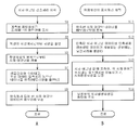
도 4(A)는, 이 입체 화상 표시 시스템에서의 시차 어긋남 검출 처리의 개략을 도시하고 있다. 시차 어긋남 해석부(5)에서는, 시차 어긋남을 입체 화상 표시 장치(10)의 표시 화면 전체에서 계측하고, 개략, 이하의 순서로 시차 어긋남 데이터를 작성한다. 시차 어긋남 데이터의 취득은, 입체 화상 표시 장치(10)의 사용의 시작에 1회 행하면 좋다. 또한, 경시변화 등으로 시차 어긋남량이 변한 때에, 재차 행하여도 좋다. 먼저, 계측용 화상 출력부(51)에 의해, 특정한 계측용 패턴 화상을 표시 패널(2)에 표시한다(스텝 S1). 다음에, 특정한 시점에서 입체 화상 표시 장치(10)의 화면을 카메라(4)로 촬영한다(스텝 S2). 그 후, 카메라(4)에 의해 촬영된 화상을 시차 어긋남 검출부(52)에서의 해석함으로써 시차 어긋남을 검출한다(스텝 S3).Fig. 4A shows the outline of the parallax shift detection processing in this stereoscopic image display system. In the parallax
예를 들면 도 5에 도시한 바와 같이, 표시 패널(2)의 각 색의 서브 픽셀이, 수평 방향으로 제k-2, 제k-1, 제k, 제k+1, 제k+2, 제k+3의 시점에 대응하고, 각 서브 픽셀에 각 시점에 대응하는 시차 화상이 표시되는 것으로 한다. 시차 어긋남이 없는 이상적인 상태에서는, 제k의 시점에서 카메라(4)로 입체 화상 표시 장치(10)를 촬영하면, 제k의 시점에 대응하는 서브 픽셀만이 관찰된다. 시차 어긋남이 있는 상태에서는, 제k 이외의 시점에 대응하는 서브 픽셀이 관찰된다. 그래서, 특정한 시점(예를 들면 제k의 시점)에 대응하는 서브 픽셀과 다른 시점에 대응하는 다른 서브 픽셀을 특정한 계측용 패턴 화상을 형성하기 위해 발광시키고, 특정한 시점에서 입체 화상 표시 장치(10)를 촬영한다. 그리고, 촬영된 특정한 계측용 패턴 화상을 해석함으로써 시차 어긋남을 검출한다. 이 계측용 패턴 화상의 해석 방법으로서는, 후술하는 바와 같이 예를 들면, 계측용 패턴 화상의 색의 변화를 해석하는 방법과, 휘도의 변화를 해석하는 방법이 있다.For example, as shown in FIG. 5, the subpixels of each color of the
예를 들면, 특정한 시점에 대응하는 특정한 색의 서브 픽셀과, 다른 시점에 대응하는 다른 색의 서브 픽셀이 동시에 발광하는 특정한 계측용 패턴 화상을 표시 패널(2)에 표시한 상태에서, 특정한 시점에서 입체 화상 표시 장치(10)를 촬영한다. 그리고, 특정한 시점에서 촬영된 특정한 계측용 패턴 화상의 색의 변화를 해석함으로써 시차 어긋남을 검출한다(후술하는 구체예 1 및 2). 또는, 특정한 시점에 대응하는 서브 픽셀과, 다른 시점에 대응하는 서브 픽셀이 시분할로 발광하는 특정한 계측용 패턴 화상을 표시 패널(2)에 표시한 상태에서, 특정한 시점에서 입체 화상 표시 장치(10)를 촬영한다. 그리고, 특정한 시점에서 촬영된 특정한 계측용 패턴 화상의 휘도의 변화를 해석함으로써 시차 어긋남을 검출한다(후술하는 구체예 3).For example, in a state where a specific measurement pattern image in which subpixels of a specific color corresponding to a specific viewpoint and subpixels of different colors corresponding to different viewpoints simultaneously emit light is displayed on the
시차 어긋남 검출부(52)에서는, 필요에 응하여 샘플링하여 데이터를 솎아낸 시차 어긋남 데이터를 생성한다. 또한, 데이터 압축부(53)에서 기존의 데이터 압축 처리 등으로 데이터를 압축한 시차 어긋남 데이터를 생성한다(스텝 S4). 이에 의해, 데이터 보존 메모리(31)에서 보존하기 위한 메모리량을 줄인다. 압축 처리 등이 된 시차 어긋남 데이터를 데이터 압축부(53)로부터 입체 화상 표시 장치(10)의 데이터 보존 메모리(31)에 기록하여, 시차 어긋남 데이터를 보존한다(스텝 S5).The parallax
(입체 화상의 표시 처리의 요약)(Summary of display processing of stereoscopic image)
도 4(B)는, 이 입체 화상 표시 시스템에서의 시차 어긋남 데이터를 이용한 입체 화상 표시의 처리의 개략을 도시하고 있다. 입체 화상 표시 장치(10)에서는, 입체표시용의 시차 합성 화상을 표시 패널(2)에 표시하는 경우에, 개략, 이하의 순서로 시차 어긋남 데이터에 따라 화상의 보정을 한 후에 표시한다. 먼저, 데이터 보존 메모리(31)에 보존되어 있는 압축된 시차 어긋남 데이터를 판독한다(스텝 S11). 다음에, 판독 시차 어긋남 데이터를 데이터 압축 해제부(32)에서 압축해제하여 시차 어긋남 보정부(33)에 출력한다. 샘플링된 시차 어긋남 데이터인 경우에는, 시차 어긋남 보정부(33)는, 화소에 관한 시차 어긋남 데이터를 보간 연산하여 구한다(스텝 S12). 시차 어긋남 보정부(33)는, 시차 어긋남 데이터에 의거하여, 표시 패널(2)의 화소 마다(서브 픽셀 마다)에 시차 어긋남이 보상되도록, 화소 위치의 이동 등을 행하여, 표시 패널(2)에 표시하는 시차 합성 화상을 보정한다(스텝 S13). 보정 후의 시차 합성 화상을 표시 패널(2)의 화면에 표시한다(스텝 S14).Fig. 4B shows an outline of a process of stereoscopic image display using parallax deviation data in this stereoscopic image display system. In the stereoscopic
(시차 어긋남 검출 처리의 구체예 1)(Specific example 1 of parallax deviation detection processing)
상기한 시차 어긋남 검출 처리의 상세한 구체예를 이하에 설명한다.The specific example of said parallax shift detection process is demonstrated below.
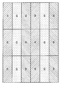
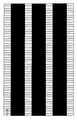
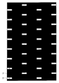
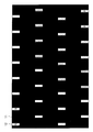
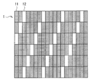
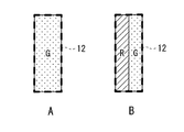
계측용 화상 출력부(51)에 의해, 특정한 계측용 패턴 화상을 표시 패널(2)에 표시한다. 계측용의 패턴은, 표시 패널(2)의 화면에 표시하는 화상 데이터로서, 시차 순서로 R, G, B, R, G, B, …와 같이, R, G, B를 처례로 시차마다 반복한 화상을 준비한다. 또한, 화면의 픽셀 화소(서브 픽셀)와 패럴랙스 배리어(1)의 슬릿부(12)와의 상대적인 위치 관계에서, 수직 방향의 시차 어긋남의 계측 데이터에의 영향을 경감하기 위해, 이 화상의 수직 방향을 솎아낸다. 이와 같이 함으로써, 입체표시의 시차에 직접 강한 영향이 있는 수평 방향에서는, 화면의 서브 픽셀과 슬릿부(12)와의 상대적인 위치 관계의 어긋남이, 시차 어긋남이 되고, 그 시차 어긋남이 직접 색의 변화로서 나타난다. 한편, 수직 방향에서는, 어긋남이 발생한 경우에도, 패턴을 솎아내고 있기 때문에 (어긋났다고 하여도 수직 방향의 옆은 솎아내고 있기 때문에), 다른 색이 되지 않고 무색의 흑(black)으로 될 뿐이고, 색의 변화로서 나타나지 않는다. 이 방법에 의한, 계측용 패턴 화상의 예를, 도 6에 도시한다. 도 6의 패턴 예에서는, 6시차의 경우를 나타내고 있다. 시차의 순서로, 화상의 왼쪽부터 R, G, B, R, G, B, …의 컬러로 배열되고 있다. 또한, 수직 방향의 화소는 2/3로 솎아내고 있다. 이 도 6에서는, R, G, B의 직사각형 패턴의 각각이 서브 픽셀이다. 그리고, 인접하는 R, G, B의 직사각형을 통합한 것이, 통상의 2차원 표시를 행하는 경우의 1화소에 상당한다. R, G, B의 3색의 합성으로 백(white)이 표시된다. 도 6에서, 흑으로 되어 있는 부분은 화소의 발광이 없고, 검게 표시되어 있는 부분이다. 즉, 수평 방향으로 백(white)의 선이 표시되고, 수직 방향에서는 2개 걸러서의 백선 표시로 되어 있다. 이 패턴을 화면상에 표시한다. 도 6에 도시한 예로 한하지 않고, 계측용 패턴 화상으로서는, 시차 어긋남의 대소나 치우침 등에 응하여, 후의 데이터 해석을 행하기 쉬운 적절한 패턴을 적절히 이용하면 좋다.The measurement
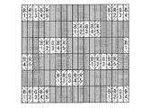
도 6에 도시한 바와 같은 계측용 패턴 화상을 표시한 상태에서, 시점의 하나로부터 보이는 화면의 R, G, B의 컬러 줄무늬를 카메라(4)로 촬영한다. 촬영된 화상은, 서브 픽셀을 판별할 수 있는 해상도는 필요없고, R, G, B의 색이 서서히 변화하는 줄무늬의 패턴을 얻을 수 있으면 좋다. 도 3에서는, 2번째의 시차 화상(제2 시점 화상)의 G색이 특정한 시점 화상으로서 관찰되는 특정한 시점에서 입체 화상 표시 장치(10)를 촬영하고 있는 예를 도시하고 있다. 도 8은, 도 3의 특정한 시점에서 관찰하는 경우에 있어서의, 도 6에 도시한 계측용 패턴 화상과 도 7에 도시한 패럴랙스 배리어와의 조합을 모식적으로 나타내고 있다. 도 9에서는 다시, 계측용 패턴 화상에서 검게 표시되어 있는 부분에 대응하는 슬릿부(12)를 검게 한 상태를 나타내고 있다. 도 9에 도시한 상태를, 카메라 촬영의 화상으로 보면, 각 서브 픽셀 사이가 분리하여 보이지 않고, 전체가 일양한 색으로 보인다. 이 도 9의 예에서는, 이상적으로는, 전체가 일양한 녹색으로 보이고 있다. 이 경우의 이상적이란, 표시 패널(2)의 각 화소(서브 픽셀)와 각 슬릿부(12)의 상대적인 위치 관계의 어긋남이 없는(시차 어긋남이 없다) 경우이다.With the measurement pattern image as shown in FIG. 6 being displayed, color stripes of R, G and B of the screen seen from one of the viewpoints are photographed by the
화면의 서브 픽셀과 슬릿부(12)와의 상대적인 위치 관계의 어긋남이 있는 경우에는, 촬영 화상의 분석으로부터 시차 어긋남을 검출한다. 상대적인 위치 관계의 어긋남이 있는 경우의 예로서, 도 10에 도시하는 바와 같이 패럴랙스 배리어(1)의 슬릿부(12)의 위치가, 도 7이 이상적인 배리어 패턴에 대해 어긋나 있는 경우로 설명한다. 도 10에서는, 우하측의 슬릿부(12)의 위치가 1서브 픽셀, 또는 0.5서브 픽셀, 왼쪽으로 어긋나 있는 상황을 나타내고 있다. 이 상황하에서, 도 6에 도시한 계측용 패턴 화상을 표시하여 카메라(4)로 촬영한 상태를 도시한 도면이, 도 11이다. 또한, 패럴랙스 배리어(1)의 슬릿부(12)에 광이 오지 않는 부분을 흑으로 표시한 상태를 나타냈던 것이, 도 12이다. 도 12에서는, 우하측의 슬릿부(12)의 위치가 1서브 픽셀, 또는 0.5서브 픽셀, 왼쪽으로 어긋나 있는 부분에서는, G의 왼편의 R이 1서브 픽셀, 또는 0.5서브 픽셀 보이는 상황을 나타내고 있다. 이것을, 카메라 촬영의 화상으로 보면, 각 서브 픽셀 사이가 분리되어 보이지 않고, 전체가 색을 띠어 보인다. 단, 전체가 균일한 녹색으로 보이지 않고, 이 도면에서는 녹색이 붉게 변화하고 있는 양상이 보인다. 시차 어긋남 검출부(52)에서는, 이 색의 변화를 해석하고, 시차 어긋남량을 산출한다. 구체적인 어긋남량의 산출 방법은 후술한다.When there is a shift in the relative positional relationship between the subpixels of the screen and the
입체 화상 표시 장치(10) 내의 데이터 보존 메모리(31)에 기록 보존하기 위해, 샘플링하여 데이터를 솎아낸다. 또한, 데이터 압축부(53)에서 기존의 데이터 압축 처리 등으로 데이터를 압축한다. 샘플링하여 데이터를 솎아내는 방법을, 도 13에 도시한다. 시차 어긋남 보상을 위한 시차 어긋남 데이터는 각 서브 픽셀수 필요하게 되고, 도 13과 같은 풀 HD의 화면에서는, 모든 서브 픽셀수=6220800(1920×3×1080)에서 되고, 방대한 데이터가 된다. 그러나, 실제의 시차 어긋남값은 완만한 변화를 하기 때문에, 도 13의 샘플링점과 같은 솎아냄을 행하는 것이 가능하다. 이 경우에는, 시차 어긋남 데이터 수는, 샘플링점의 수=231(33샘플×7샘플)이 된다. 또한 솎아냄을 행하여도, 시차 어긋남 보정부(33)에서 시차 어긋남 데이터를 사용할 때에 용이하게 보간을 할 수 있기 때문에, 샘플링점의 데이터만을 취하여, 시차 어긋남 데이터로 한다. 또한, 샘플링한 시차 어긋남 데이터에, 기존의 압축 기술 등을 사용하여 더욱, 시차 어긋남 데이터를 압축한다.In order to record and save the data in the
압축 처리 등이 된 시차 어긋남 데이터를 데이터 압축부(53)로부터 입체 화상 표시 장치(10)의 데이터 보존 메모리(31)에 기록하여, 시차 어긋남 데이터를 보존한다.The parallax shift data which became compression processing etc. is recorded from the
(카메라(4)에 의한 촬영 화상으로부터 시차 어긋남을 산출하는 방법의 구체예 1)(Specific example 1 of the method of calculating parallax shift | offset from the picked-up image by camera 4)
카메라(4)에 의한 촬영 화상을 해석하여, 시차 어긋남값을 산출하는 방법에 관해, 더한층의 구체예를 이하에 설명한다. 기본적으로는, 촬영 화상의 R, G, B의 색의 줄무늬의 상황으로부터, 시차 어긋남값을 산출한다.A specific example of the method of analyzing the picked-up image by the
제1의 스텝에 있어서, 측정계의, R, G, B의 신호 레벨의 조정을 행한다. 표시 패널(2)의 화면이나 카메라(4)의 화이트 밸런스 등이 맞지 않으면, 촬영 화상을 해석하여 시차 어긋남값을 산출할 때에 오차가 생기기 때문에, 처음에 화이트 밸런스 등의 조정을 행하여, R, G, B의 신호 레벨을 맞추어 둔다. 맞추는 방법은, 모든 시차에 R의 신호만, G의 신호만, 또는 B의 신호만을 입력하고, 카메라(4)로 촬영한 때의, R의 신호만, G의 신호만, 또는, B의 신호만의 촬영 화상의, R, G, B의 각각의 컬러의 값이 같게 되도록 조정한다.In the first step, the signal levels of R, G, and B of the measurement system are adjusted. If the screen of the
제2의 스텝에 있어서, 표시 패널(2)의 화면에 계측용 패턴 화상을 표시하고, 그것을 시점의 하나로부터 카메라(4)로 촬영한다. 제3의 스텝에 있어서, 촬영하는 촬영 화상으로부터, 화면 부분을 오려내고, 해석을 시작한다. 제4의 스텝에 있어서, 화면 부분의 촬영 화상을, R, G, B의 각각의 색으로 분해한다.제5의 스텝에 있어서, 서브 픽셀 마다, 분해된 R, G, B의 각각의 컬러의 값을 구한다. 제6의 스텝에 있어서, 구한, R, G, B의 각각의 컬러의 값중에서, 최대 컬러와 다음의 컬러로부터 그 비율을 구한다. 비율 50%에서 그 서브 픽셀은, 이웃하는 서브 픽셀이 50%씩 보이고 있는 것이 되고, 시차 어긋남값은 -0.5 또는 +0.5가 된다(도 22 참조).In a 2nd step, the pattern image for a measurement is displayed on the screen of the
제7의 스텝에 있어서, 또한, R, G, B의 각각의 컬러의 값중에서, 최대 컬러의 신호의 값이, 항목 1. 에서 R, G, B의 신호 레벨을 맞추고 있는데, 이 조정하고 같게 한 R, G, B의 각각의 컬러의 값과 같은 값이 나와 있는 서브 픽셀은, 시차 어긋남이 없고, 시차 어긋남값은 0이 된다. 제8의 스텝에 있어서, 시차 어긋남이 없고, 패럴랙스 배리어(1)의 슬릿부(12)와, 표시 패널(2)의 서브 픽셀과의 관계가 도 23(A)와 같이 되어 있는 경우는, 단색이 된다. 이 경우의 가(temporary)시차 어긋남량은 0이 된다. 슬릿부(12)와 표시 패널(2)의 서브 픽셀의 관계가 도 23(B)와 같이 되어, 시차 어긋남이 생긴 경우(도 23(B)의 경우는 시차 어긋남량이 0.5)는, 녹색으로부터 어긋난 색으로서 관측된다. 도 23(B)에서는, 옆의 서브 픽셀로부터의 광이 입사하고 있고, 녹+적=황색으로서 관측된다. 이 경우, 측정된 색으로부터, 녹색과 적색의 비율이 몇%인지를 계산할 수 있다. 구체적으로는, xy 또는 uv색도 좌표에서의 녹 100%와 적 100%의 2개의 색도점에 대해, 혼색한 측정 색도점이 어느 좌표에 있는지를 계산하고, 녹 100%와 적 100%의 색도점까지의 거리에 의해 안분하면 좋다. 녹과 청색의 화소의 혼합이나, 적과 청색의 화소의 혼합에서도 같은 수법을 이용할 수 있다. 이에 의해, 각 화소의 가시차 어긋남의 값을 0보다 크게, 1.0 미만의 값에 가(temporally)설정할 수 있다.In the seventh step, among the values of the respective colors of R, G, and B, the value of the signal of the maximum color adjusts the signal levels of R, G, and B in
제9의 스텝에서. 다음에 최종적인 시차 어긋남량의 산출을 행한다. 그를 위해 각각의 서브 픽셀에서의 시차 어긋남값은, 연속성이 유지되어 있다고 한다. 즉, 이웃하는 서브 픽셀의 시차 어긋남의 값은 대체로 같은 값이 되고, 매끈하게 변화하고, 가파르게는 변화하지 않는다고 한다. 이 조건하에서, 각각의 서브 픽셀의, 항목 8.에서 산출한 가시차 어긋남값으로부터, 최종적인 시차 어긋남값을 구한다. 이 때, 연속성과 함께, 각각의 서브 픽셀에서의 R, G, B의 각각의 컬러의 값중에서의 최대 컬러의 색을 고려한다. 계측용 패턴 화상은, 각각의 시차에, 표시 패널(2)의 화면에 표시하는 화상 데이터로, 시차 순서로 R, G, B, R, G, B, …와 같이, R, G, B를 차례로 시차마다 반복한 화상으로 하고 있기 때문에, 그 색의 천이로 시차 어긋남이 어느 방향으로 어긋나 있지를 알 수 있다. 한쪽 방향으로 서서히 어긋나 있는 경우는, 시차 순서로 세트한 R, G, B, R, G, B, … 순서로 최대 컬러의 신호치의 색이 변한다. 또한, 역방향으로 서서히 어긋나 있는 경우는, 시차 순서로 세트한 R, G, B, R, G, B, …의 순서와는 역으로, B, G, R, B, G, R, …의 순서로 최대 컬러의 신호치의 색이 변한다. 이 색의 천이를 기초로 어느 방향으로 어긋나 있는지를 알 수 있다. 따라서, 연속성과 색의 변화를 쫓음으로써, 전체의 각각의 서브 픽셀의 ±의 값을 정할 수 있다. 연속하여, 시차 어긋남량이 변함에 의해, 최종적으로 시차 어긋남량을 결정할 수 있다. 도 24에 도시하는 바와 같이, 상기 8.에서 가설정한 시차 어긋남량과, 컬러의 변화량으로부터 최종적인 시차 어긋남량을 계산할 수 있다.In the ninth step. Next, the final amount of parallax deviation is calculated. For this reason, it is assumed that the parallax shift value in each sub-pixel is maintained in continuity. That is, it is said that the value of parallax shift | offset of neighboring subpixel becomes substantially the same value, changes smoothly, and does not change sharply. Under this condition, the final parallax shift value is obtained from the visible difference shift value calculated in
이와 같이, 시차 어긋남 보정에 사용하는 각각의 서브 픽셀 마다의 시차 어긋남값을 산출할 수 있다.In this way, the parallax shift value for each sub-pixel used for parallax shift correction can be calculated.
(시차 어긋남 검출 처리, 시차 어긋남 산출 방법의 구체예 2)(Specific example 2 of parallax deviation detection processing, parallax deviation calculation method)
상기한 구체예 1에 의한 시차 어긋남 검출 처리에서는, 3시점, 6시점, 또는 9시점등의, 3의 배수의 시차수로 입체표시를 행하는 것을 전제하였다. 5시점 등의 시차수가 3의 배수가 아닌 경우에는, 도 6에 도시한 계측용 패턴 화상을 표시하면, 시차 어긋남이 없는 경우라도, 이하에서 설명하는 바와 같이, 패럴랙스 배리어(1)를 통하여 같은 색의 표시가 관측되지 않는 상태가 된다.In the parallax misalignment detection process according to the specific example 1 described above, it is assumed that stereoscopic display is performed with a parallax of multiples of three, such as three, six, or nine. When the parallax such as 5 o'clock is not a multiple of 3, if the measurement pattern image shown in Fig. 6 is displayed, even when there is no parallax deviation, the same through the
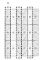
이하에서는, 시점수 5인 경우의 패럴랙스 배리어(1)를 이용하는 경우를 예로 설명을 행한다. 도 14는, 패럴랙스 배리어(1)가, 시점수 5의 스텝 배리어 방식인 경우의 구성례를 도시하고 있다. 수평 방향으로는, 표시 패널(2)의 5개의 서브 픽셀 마다 슬릿부(12)가 설치되어 있다. 또한, 서브 픽셀의 크기가 수평 1 : 수직 3의 비율인 것으로 하면, 수평 1 : 수직 3의 각도로, 경사 방향으로 연속하여 슬릿부(12)가 설치되어 있다.Hereinafter, the case where the
도 15 및 도 16은, 입체 화상 표시 장치(10)에서 5시점에서의 입체표시를 행하는 경우에, 도 6에 도시한 계측용 패턴 화상을 도 14의 패럴랙스 배리어를 통하여 제2 시점에서 관찰한 상태를 모식적으로 도시하고 있다. 도 16의 A-A선 부분의 단면이 도 15에 대응하고 있다. 표시 패널(2)의 서브 픽셀 부분에 붙인 번호 1, 2, 3, 4, 5는, 제1 내지 제5의 시점에 대응하는 시차 화상의 번호(시점 번호)를 나타내고 있다. 시차 어긋남이 없는 이상적인 상태에서는, 카메라(4)에는 화면 전체에서, 제2의 시점에 대응하는 시차 화상(제2 시점 화상)만이 촬영된다. 상기한 구체예 1에서는, 촬영 화상은, 도 9에 도시한 바와 같이 전체에 동일 색(G)의 서브 픽셀만이 관측되는 상태가 된다. 그러나, 도 15 및 도 16의 경우에는, 같은 제2의 시점라도, R, G, B의 3색이 측정되어 버리고, 단색으로 표시되지 않는다. 이 때문에, 상기한 구체예 1의 방법으로는, 시차 어긋남량을 측정할 수가 없다.15 and 16 show that the measurement pattern image shown in FIG. 6 is observed from the second viewpoint through the parallax barrier of FIG. 14 when the stereoscopic
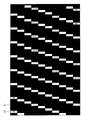
따라서, 시차 어긋남이 없는 경우에 패럴랙스 배리어(1)를 통하여 카메라(4)로 관측되는 화상이 단색으로 되도록, 도 6과는 다른 계측용 패턴 화상을 결정할 필요가 있다. 5시점의 경우에는, 계측용 패턴 화상을 도 17과 같이 하면 좋다. 5시점의 경우에는, 제1 내지 제5까지의 임의의 어느 시점(예를 들면 제3 시점이라고 한다)을 특정한 시점으로 정하고, 또한, 그 특정한 시점에 대응하는 서브 픽셀에 표시하는 색을 R, G, B중 임의의 1색으로 정한다(이 경우는 G). 그리고, 특정한 시점인 제3 시점에 대응하는 서브 픽셀중, G에 대응하는 서브 픽셀과, 그 좌우에 존재하는 다른 시점(제1 시점, 제2 시점, 제4 시점, 및 제5 시점)의 서브 픽셀만을 발광시키는 화상을 계측용 패턴 화상(도 17)으로 한다. 이에 의해, 시차 어긋남이 없는 이상적인 상태에서는, 카메라(4)로 특정한 제3 시점에서 촬영하면, 예를 들면 도 18에 도시한 바와 같이, 단색의 색(G)이 화면 전체에서 관측된다. 시차 어긋남이 있는 경우는, 1색이 아니라, 복수의 색이 측정되게 되기 때문에, 상기한 구체예 1과 같은 원리로 촬영 화상의 색의 변화를 해석함으로써 시차 어긋남을 검출할 수 있다. 이에 의해, 3의 배수 이외의 시점수로의 입체표시를 행하는 경우라도, 시차 어긋남량을 산출할 수 있다.Therefore, it is necessary to determine the measurement pattern image different from FIG. 6 so that the image observed with the
(시차 어긋남 검출 처리, 시차 어긋남 산출 방법의 구체예 3)(Specific example 3 of parallax deviation detection processing, parallax deviation calculation method)
상기 구체예 1 및 구체예 2에서는, 계측용 패턴 화상의 색의 변화를 해석함으로써 시차 어긋남을 검출하도록 하였지만, 구체예 3으로서, 색의 변화를 이용하지 않고서 시차 어긋남을 검출하는 수법을 설명한다. 카메라(4)는, 도 3이나 도 15인 경우와 마찬가지로, 시차 어긋남이 없는 이상적인 상태에서는, 어느 특정한 시점(도 3, 도 15에서는 제2 시점)에 대응하는 서브 픽셀로부터의 광만이 입사하고, 다른 시점에 대응하는 서브 픽셀로부터의 광은 입사하지 않는 위치 부근에 설치한다.In Example 1 and Example 2, the parallax shift was detected by analyzing the change in the color of the pattern image for measurement, but as Example 3, a method of detecting the parallax shift without using the change in color is described. As in the case of FIG. 3 or FIG. 15, in the
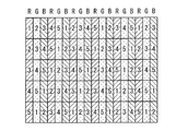
이하에서는, 상기 구체예 2와 마찬가지로, 시점수 5인 경우의 패럴랙스 배리어(1)(도 25)를 이용하는 경우를 예로 설명을 행한다. 도 19는, 시점수가 5개인 경우의 표시 패널(2)의 각 서브 픽셀과 각 시점와의 대응 관계를 도시하고 있다. 도 19에어서, 표시 패널(2)의 서브 픽셀 부분에 붙인 번호 1, 2, 3, 4, 5는, 제1 내지 제5의 시점에 대응하는 시차 화상의 번호(시점 번호)를 나타내고 있다. 본 구체예에서는, 특정한 시점(예를 들면 제2 시점)에서 입체 화상 표시 장치(10)를 촬영하는데, 표시 패널(2)에는 특정한 시점에 대응하는 서브 픽셀과, 다른 시점에 대응하는 서브 픽셀이 시분할로 발광하는 특정한 계측용 패턴 화상을 표시 패널(2)에 표시한다. 다른 시점에 대응하는 서브 픽셀에 관해서는, 적어도 특정한 시점(예를 들면 제2 시점)에 대해 이웃하는 시점(예를 들면 제1 시점 및 제3 시점)에 대응하는 서브 픽셀에 관해 시분할로 발광시킨다. 여기서는, 모든 시점에 대응하는 서브 픽셀을 순차적으로, 시분할로 발광시키는 것으로 한다. 예를 들면, 우선, 제1의 시점에 대응하는 서브 픽셀만을 점등(발광)시키고, 그 밖의 서브 픽셀을 소등한다. 이 때, 제1 시점에 대응하는 R, G, B의 모든 색의 서브 픽셀을 점등하고, 이 제1 시점 화상을 특정한 시점(예를 들면 제2 시점)에서 카메라(4)로 촬영하고, 기록한다. 그리고, 다음에 제2 시점에 대응하는 R, G, B의 모든 색의 서브 픽셀을 점등하고, 그 제2 시점 화상을 특정한 시점(예를 들면 제2 시점)에서 카메라(4)로 촬영하고, 기록한다. 이하, 마찬가지로 하여 순차적으로, 제5 시점까지 촬영하고, 기록을 행하다. 또한, 하나의 시점 화상에 관해 R, G, B의 모든 서브 픽셀을 점등시켜도, 서브 픽셀의 크기는 충분 작기 때문에, 화면 전체로서는 흑백의 농담으로서 관찰된다.Hereinafter, similarly to the specific example 2, the case where the parallax barrier 1 (FIG. 25) in the case of the
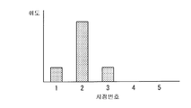
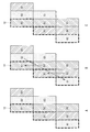
그리고, 화면상의 어느 화소의 휘도에 관해, 점등시킨 시점 마다의 분포를 평가한다. 도 20, 도 21에 도시하는 그래프는, 화면상의 어느 위치에서, 각 시점 마다의 촬영 화상의 휘도를 나타내고 있다.Then, the distribution for each time of lighting is evaluated for the luminance of any pixel on the screen. The graphs shown in FIG. 20, FIG. 21 show the brightness | luminance of the picked-up image for every viewpoint at some position on the screen.
카메라(4)를 제2 시점에 설치한 경우, 시차 어긋남이 없는 이상적인 상태에서는 5종류의 시점 화상중, 제2 시점 화상의 휘도가 가장 높고, 인접하는 제1 시점 화상, 제3 시점 화상의 휘도는 소량이고, 거의 동일하게 된다(도 20). 이에 대해, 시차 어긋남이 있는 경우에는, 예를 들면 도 21과 같이 된다. 시차 어긋남이 있음으로써, 예를 들면, 제2 시점 화상으로부터 뿐만 아니라, 제3 시점 화상으로부터의 광도 카메라(4)에 입사하는 경우는, 제1 시점 화상의 휘도가 감소하고, 제3 시점 화상의 휘도가 증가한다.When the
이 시차 어긋남량은, 예를 들면, 이하와 같이 구할 수 있다. 시분할로 각 시점 화상을 표시하기 때문에, 화면의 임의의 포인트에서의, 각 시점 화상마다의 휘도의 중심 위치를 계산할 수 있다. 입체 화상 표시 장치(10)의 화면의 중앙에서의, 각 시점 화상마다의 중심 위치를 뺌에 의해, 화면 내의 중심 위치의 변화량을 구할 수 있다.This amount of parallax shift can be calculated | required as follows, for example. Since each viewpoint image is displayed by time division, the center position of the brightness | luminance for every viewpoint image can be calculated in arbitrary points of a screen. By subtracting the center position of each viewpoint image in the center of the screen of the stereoscopic
예를 들면 화면을 어느 영역으로 분할(예를 들면 32×32개의 영역으로 분할)하고, 각각의 분할 영역에서, 도 20, 도 21에 도시하는 바와 같은 시점 화상마다의 휘도 분포를 구한다. 화면 중심의 시점 휘도의 중심 위치가 2.5라고 한다. 시차 어긋남이 없는 경우는, 제2 시점에 카메라(4)를 설치한 경우는, 화면 중심의 시차 어긋남량은, 2.5-2=+0.5라고 구할 수 있다. 그리고, 화면의 오른쪽 끝의, 중심 시점가 3.5였은 경우는, 3.5와 2.0의 차인 +1.5의 시차 어긋남값으로서 구할 수 있다.For example, the screen is divided into certain regions (e.g., divided into 32 x 32 regions), and the luminance distribution for each viewpoint image as shown in Figs. 20 and 21 is obtained in each divided region. The center position of the viewpoint luminance at the center of the screen is 2.5. When there is no parallax shift, when the
상기 구체예 3의 수법을 이용함으로써, 색의 변화량에 의하지 않고, 휘도량에 의해 시차 어긋남량을 구할 수 있다. 색의 변화량을 구하는 것은, 휘도의 변화량을 구한 것보다도 계산량이 많기 때문에, 휘도량에 의해 시차 어긋남량을 구하는 수법의 쪽이 시차 어긋남 검출부(52)의 구성을 단순한 것으로 할 수 있는 이점이 있다. 또한, 상기 설명에서는, 시점수가 5인 경우를 예로 하였지만, 전문가법은 입체표시의 시점수에 관계없이 이용할 수 있다는 이점이 있다.By using the method of the said specific example 3, the amount of parallax shift | offset | difference can be calculated | required not with the amount of change of color. Since the amount of change in color is larger than that in which the amount of change in luminance is calculated, the method of calculating the amount of parallax deviation based on the amount of luminance has an advantage that the configuration of the parallax
(입체 화상의 표시 처리의 상세한 구체예)(Detailed example of display processing of a stereoscopic image)
상기한 입체 화상의 표시 처리의 상세한 구체예를 이하에 설명한다.The specific example of the display process of the above-mentioned three-dimensional image is demonstrated below.
먼저, 데이터 보존 메모리(31)에 보존되어 있는 압축된 시차 어긋남 데이터를 판독한다. 그 후, 판독 시차 어긋남 데이터를 데이터 압축 해제부(32)에서 압축해제하여 시차 어긋남 보정부(33)에 출력한다. 샘플링된 시차 어긋남 데이터인 경우에는, 시차 어긋남 보정부(33)는, 화소에 관한 시차 어긋남 데이터를 보간 연산하여 구한다. 이 때에, 가장 용이한 것은 선형보간이다. 각각의 샘플링점 사이의 시차 어긋남값을, 선형보간으로 구함으로써, 화면 전체의 서브 픽셀의, 시차 어긋남 데이터를 얻는다. 샘플링 보간 방법은, 직선보간만이 아니라, 적절히 곡선보간, 또는 다른 방법을 사용하여도 좋다.First, the compressed parallax deviation data stored in the
시차 어긋남 보정부(33)는, 얻어진 화면 전체의 서브 픽셀의 시차 어긋남 데이터에 의거하여, 표시 패널(2)의 화소 마다(서브 픽셀 마다)에 시차 어긋남이 보상되도록, 화소 위치의 이동 등을 행하여, 표시 패널(2)에 표시하는 시차 합성 화상을 보정한다. 보정 방법에 관해서는, 그 기본을 도 22에 도시한다. 도 22(A)는 시차 어긋남의 값의 예를 도시하고 있다. 도 22(B)는, 도 22(A)의 시차 어긋남의 값에 의거하여 도 22(C)의 서브 픽셀의 화상을 보정한 예를 도시하고 있다. 도 22(B)에서는, 예를 들면, 시차 어긋남값이 +0.1인 경우에는, 좌측의 화소치를 90%로 하고, 우측의 화소치를 10%로 하여 합성하고 있다.The parallax
또한, 도 25 내지 도 27에는 시차 합성 화상의 보정의 구체예를 도시하고 있다. 도 25는, 시차 어긋남이 없는 상태에서의 서브 픽셀과 슬릿부(12)와의 관계를 도시하고 있다. 도 25 내지 도 27에서, R1, G1, B1은 도 3에서의 번호 1(제1 시점)의 시차 화상에 대응하고, R2, G2, B2는 도 3에서의 번호 2(제2 시점)의 시차 화상에 대응하고, R3, G3, B3은 도 3에서의 번호 3(제3 시점)의 시차 화상에 대응하고 있다. 시차 어긋남이 없기 때문에, 도 25에서, 슬릿부(12)는 화소(G2, R2, B2)의 위에 위치하고 있다. 도 26은, 시차 어긋남의 값이 -1.0인 경우이다. 슬릿부(12)는 도 25의 이상 상태에 대해 1서브 픽셀 왼쪽으로 시프트하고 있다. 시차 어긋남 보정부(33)는, 도 26(A)에 도시하는 바와 같이 시차 어긋남의 값이 1서브 픽셀(또는 2서브 픽셀, 3서브 픽셀 등, 서브 픽셀의 정수배)에 상당하는 경우에는, 도 26(B), (C)에 도시하는 바와 같이 시차 어긋남의 값에 응하여 다른 시차 화상(여기서는 R1, R3 등)과 특정한 시차 화상(여기서는 R2 등)을 표시하는 화소 위치의 이동을 행한다. 이에 의해, 슬릿부(12)의 바로 아래에 있는 서브 픽셀이, R2, G2, B2의 값을 표시하게 되어 보정이 실시된다.25 to 27 show specific examples of correction of parallax synthesized images. FIG. 25 shows the relationship between the subpixel and the
도 27은, 시차 어긋남의 값이 -0.7인 경우이다. 시차 어긋남의 값이 1화소 미만의 값을 포함하는 경우에는, 도 27(B), 도 27(C)에 도시하는 바와 같이 시차 어긋남의 값에 응하여 다른 시차 화상의 화소치(여기서는 R1, R3 등)와 특정한 시차 화상(여기서는 R2 등)의 화소치를 합성하는 보정을 행한다. 도 27(A)에서, 슬릿부(12)의 바로 아래는, R1, B1, G1이 70%, R2, B2, G2가 30%의 비율로 위치하고 있다. 슬릿부(12)가 서브 픽셀의 화소 사이에 걸쳐져 위치하고 있기 때문에, 시차 어긋남량에 따라, 각 서브 픽셀에서 표시하는 화상을 결정한다. 구체적으로는, 슬릿부(12)의 바로 아래에 70% 존재하는, 원래의 R1, B1, G1의 서브 픽셀에는, 70%을 제2 시점에 대응하는 R2, B2, G2로 하고, 나머지 30%을, 제1 시점에 대응하는 R1, B1, G1로 하여 혼합한다. 원래의 R2, B2, G2의 서브 픽셀에는, 70%을 제3 시점에 대응하는 R3, B3, G3로 하고, 나머지 30%을, 제2 시점에 대응하는 R2, B2, G2로 하여 혼합한다.27 is a case where the value of parallax deviation is -0.7. When the value of the parallax deviation includes a value of less than one pixel, as shown in FIGS. 27B and 27C, pixel values of different parallax images (here, R1, R3, etc.) in response to the value of parallax deviation ) And pixel values of a specific parallax image (here, R2, etc.) are combined. In Fig. 27A, just below the
이상과 같이 하여, 화상을 표시 패널(2)의 화면에 표시하는 경우에, 표시 화상의 서브 픽셀을, 표시 패널(2)의 화면의 서브 픽셀에 1대1로 대응시킨다. 시차 어긋남이 있는 경우는, 시차 어긋남분 만큼 비켜놓아 표시되도록 보정하는데, 이 때, 시차 어긋남값이 정수인 경우는, 그 수만큼, 상당하는 서브 픽셀을 시프트한다(도 25, 도 26). 그러나, 시차 어긋남값이 정수가 아닌 경우에는 단순하게 비켜놓을 수가 없기 때문에, 도 27에 도시하는 방법으로, 화상의 합성을 행한다. 서브 픽셀의 시차 어긋남값의 정수분을 제외한, 소수점 이하의 수치 비율에 따라, 서브 픽셀 값을 산출한 보정 화상을 작성한다. As described above, when the image is displayed on the screen of the
보정 후의 시차 합성 화상은 표시 패널(2)의 화면에 표시한다. The parallax composite image after correction is displayed on the screen of the
[효과][effect]
본 실시예에 관한 입체 화상 표시 시스템에 의하면, 이하의 효과를 얻을 수 있다.According to the stereoscopic image display system according to the present embodiment, the following effects can be obtained.
시차 어긋남 데이터를 데이터 보존 메모리(31)에 기억하고, 그 데이터 보존 메모리(31)에 기억된 시차 어긋남 데이터에 의거하여, 화소(서브 픽셀)마다 시차 어긋남이 보상되도록 시차 합성 화상을 보정하도록 하였기 때문에, 화면 전체에 걸쳐서 화소 마다 시차 어긋남을 억제한 양호한 입체 화상 표시를 행할 수 있다. 특히, 카메라(4)로 1시점에서 촬영한 화상만으로부터 화면 전체의 시차 어긋남값을 화상 처리에서 산출하기 때문에, PC 등을 사용하여 해석을 할 수 있고, 수초로부터 수십초에서 용이하게 해석이 가능하다. 이에 의해, 양산시의 라인의 스피드에도 대응할 수 있는 속도로의 해석을 행할 수 있다.Since the parallax shift data is stored in the
(제2의 실시예)(Second Embodiment)
다음에, 본 발명의 제2의 실시예에 관한 입체 화상 표시 시스템에 관해 설명한다. 또한, 상기 제1의 실시예에 관한 입체 화상 표시 시스템과 실질적으로 동일한 구성 부분에는 동일한 부호를 붙이고, 적절히 설명을 생략한다.Next, the three-dimensional image display system according to the second embodiment of the present invention will be described. In addition, the same code | symbol is attached | subjected to the substantially same component part as the stereoscopic image display system which concerns on the said 1st Example, and description is abbreviate | omitted suitably.
상기 제1의 실시예에서는, 특정한 계측용 패턴 화상을 표시 패널(2)에 표시하고, 화면을 카메라(4)로 촬영하여 화상 해석함으로써, 화면 전체의 시차 어긋남 데이터를 얻도록 하였다. 이에 대신하여, 시차 어긋남의 검출을 예를 들면, 현미경에 의한 계측이나, 레이저 계측기에 의한 종래로부터 알려져 있는 계측 수법으로 행하여도 좋다.In the first embodiment, a specific measurement pattern image is displayed on the
(제3의 실시예)(Third Embodiment)
다음에, 본 발명의 제3의 실시예에 관한 입체 화상 표시 시스템에 관해 설명한다. 또한, 상기 제1의 실시예에 관한 입체 화상 표시 시스템과 실질적으로 동일한 구성 부분에는 동일한 부호를 붙이고, 적절히 설명을 생략한다.Next, the three-dimensional image display system according to the third embodiment of the present invention will be described. In addition, the same code | symbol is attached | subjected to the substantially same component part as the stereoscopic image display system which concerns on the said 1st Example, and description is abbreviate | omitted suitably.
상기 제1의 실시예는, 예를 들면, 입체 화상 표시 장치(10)의 제조시의 장치 조립에 있어서, 표시 패널(2)의 화면의 서브 픽셀과 패럴랙스 배리어(1)의 슬릿부(12)와의 상대적인 위치 관계에, 조립 오차, 편차 등에 의해 어긋남이 발생한 경우의 시차 어긋남의 보상이다.In the first embodiment, for example, in the assembly of a device in the manufacture of the stereoscopic
본 실시예는, 입체 화상 표시 장치(10)의 생산시가 아니라, 입체 화상 표시 장치(10)의 사용시에 관한 것이다. 입체 화상 표시 장치(10)를 계속 사용한 경우에, 경시변화로 화면의 서브 픽셀과 패럴랙스 배리어(1)의 슬릿부(12)와의 상대적인 위치 관계에 어긋남이 생겨 온 경우에, 상기 제1의 실시예와 마찬가지의 시차 어긋남 검출 처리를 행하고, 새로운 시차 어긋남값을 작성하고, 입체 화상 표시 장치(10) 내의 데이터 보존 메모리(31)에 기록하고, 오래된 시차 어긋남값을 그 시점이 새롭게 작성한 시차 어긋남값으로 치환한다. 입체 화상 표시 장치(10)의 사용시에, 시차 어긋남에 대해, 입체 화상 표시 장치(10)의 생산시의 시차 어긋남이 없는 상태로 되돌릴 수 있다. 본 실시예는 예를 들면, 입체 화상 표시 장치(10)의 메인터넌스(maintenance)로서 행할 수 있다.This embodiment relates to the use of the stereoscopic
(제4의 실시예)(4th Example)
다음에, 본 발명의 제4의 실시예에 관한 입체 화상 표시 시스템에 관해 설명한다. 또한, 상기 제1의 실시예에 관한 입체 화상 표시 시스템과 실질적으로 동일한 구성 부분에는 동일한 부호를 붙이고, 적절히 설명을 생략한다.Next, a stereoscopic image display system according to a fourth embodiment of the present invention will be described. In addition, the same code | symbol is attached | subjected to the substantially same component part as the stereoscopic image display system which concerns on the said 1st Example, and description is abbreviate | omitted suitably.
상기 제3의 실시예에서는, 입체 화상 표시 장치(10)의 사용시의 시차 어긋남의 계측에는, 장치 메이커의 서비스나, 장치의 관측자의 카메라(4)를 상정하고 있다. 본 실시예에서는, 카메라 부착의 입체 화상 표시 장치에 관한 것이다. 본 실시예에서는, 도 28에 도시한 바와 같이, 도 1의 시차 어긋남 해석부(5)에 상당하는 시차 어긋남 해석부(5A)를 입체 화상 표시 장치(10A)가 내장하고 있다. 카메라(4)에서는, 에너지 절약용의 사람 감지 센서 카메라, 방의 밝기나 색조로의, 텔레비전의 자동 색조절을 행하기 위한 카메라 등의 입체 화상 표시 장치(10A)에 부속한 카메라를 시차 어긋남 계측용의 카메라로서 공용한다. 입체 화상 표시 장치(10A)와 카메라(4)는 떼어냄 가능하게 하고, 시차 어긋남 계측시는 떼어내서, 계측 위치에 갖고 와서 사용한다. 카메라(4)로부터의 데이터는, 카메라(4)는 떼어냄부의 커넥터 방식, 케이블 끌어내는 방식, 광 또는 전파에 의한 무선 방식 등이면 좋다. 이 경우, 시차 어긋남 계측용의 카메라(4)를 특별하게 준비하지 않더라도, 시차 어긋남 데이터의 갱신을 행할 수 있다. 또는, 계측 전용의 카메라(4)를 입체 화상 표시 장치(10)에 부속하여도 좋다.In the third embodiment, the service of the device manufacturer and the
(제5의 실시예)(Fifth Embodiment)
다음에, 본 발명의 제5의 실시예에 관한 입체 화상 표시 시스템에 관해 설명한다. 또한, 상기 제1의 실시예에 관한 입체 화상 표시 시스템과 실질적으로 동일한 구성 부분에는 동일한 부호를 붙이고, 적절히 설명을 생략한다.Next, the three-dimensional image display system according to the fifth embodiment of the present invention will be described. In addition, the same code | symbol is attached | subjected to the substantially same component part as the stereoscopic image display system which concerns on the said 1st Example, and description is abbreviate | omitted suitably.
상기 제1의 실시예에서는, 입체 화상 표시 장치(10)의 입체표시를 위한 설계 관점이, 생산시에 어긋남이 발생한 경우의 보상이다. 즉, 입체 화상 표시 장치(10)의 생산시의 장치 조립에 있어서, 표시 패널(2)의 화면의 서브 픽셀과 패럴랙스 배리어(1)의 슬릿부(12)와의 상대적인 위치 관계에, 조립 오차, 편차 등에 의해 어긋남이 발생한 경우의, 입체 화상 표시 장치(10)의 설계 시점에서의, 시차 어긋남의 보상이다. 본 실시예에서는, 입체 화상 표시 장치(10)의 설계 시점이 아니라, 관찰자가 보는 위치에서의 시차 어긋남의 보상을 행한다. 즉, 관찰자가 소파에 앉아서 보는 경우 등의 설계 시점이 아닌 경우의 보정이다. 예를 들면 소파에 앉았던 관측자의 눈의 위치에서 촬영한 촬영 화상을 기초로 시차 어긋남 계측을 행하고, 데이터 해석하여 시차 어긋남값을 산출하고, 그 값으로 시차 어긋남 보상을 행한다.In the first embodiment, the design viewpoint for the stereoscopic display of the stereoscopic
본 실시예에 의하면, 입체 화상 표시 장치(10)의 설계 시점이 아니라, 관찰자가 보고 싶은 위치에서의 조정이 가능해진다. 결과로서, 관측자의 위치에 맞추어서, 입체 화상 표시 장치(10)의 3D를 관찰하는 경우의, 눈의 위치에 대한 입체표시의 시점의 최적화를 행할 수 있다.According to this embodiment, the adjustment can be made at the position that the viewer wants to see, not at the design time of the stereoscopic
(제6의 실시예)(Sixth Embodiment)
다음에, 본 발명의 제6의 실시예에 관한 입체 화상 표시 시스템에 관해 설명한다. 또한, 상기 제1의 실시예에 관한 입체 화상 표시 시스템과 실질적으로 동일한 구성 부분에는 동일한 부호를 붙이고, 적절히 설명을 생략한다.Next, a stereoscopic image display system according to a sixth embodiment of the present invention will be described. In addition, the same code | symbol is attached | subjected to the substantially same component part as the stereoscopic image display system which concerns on the said 1st Example, and description is abbreviate | omitted suitably.
상기 각 실시예에서는, 패럴랙스 배리어 방식의 입체 화상 표시 시스템에 관해 설명하였지만, 렌티큘러 방식에 의한 입체 화상 표시 시스템에서도, 관찰자의 눈에 대해 시차 화상이 정상적으로 입사되지 않고, 입체시의 품질에 열화가 발생하는 문제가 있기 때문에, 마찬가지의 시차 어긋남 보상을 행하는 것이 효과적이다. 이 경우, 입체 화상 표시 장치의 표시부의 기본 구성, 및 입체표시(입체시)의 기본 원리는, 종래의 일반적인 렌티큘러 방식에 의한 입체 화상 표시 장치(도 34 및 도 35)와 마찬가지이다. 즉, 예를 들면 도 1의 입체 화상 표시 장치(10)에서의 패럴랙스 배리어(1)에 대신하여, 시차 분리 구조로서, 복수의 시차 분리 부품으로서 기능하는 복수의 실린드리컬 렌즈(분할 렌즈)(113)를 갖는 렌티큘러 렌즈(101A)를 이용한다. 이 경우, 시차 어긋남은, 표시 패널(2)의 복수의 화소(서브 픽셀)와 복수의 분할 렌즈(113)의 초점 위치와의 상대적인 위치 관계의 어긋남에 의해 생긴 것을 계측하면 좋다.In each of the above embodiments, the parallax barrier type stereoscopic image display system has been described. However, even in the lenticular stereoscopic image display system, parallax images do not normally enter the observer's eyes, and deterioration in the quality of stereoscopic vision is caused. Since there is a problem that occurs, it is effective to perform similar disparity shift compensation. In this case, the basic configuration of the display portion of the stereoscopic image display device and the basic principle of stereoscopic display (in stereoscopic) are similar to those of the stereoscopic image display device (Figs. 34 and 35) by the conventional general lenticular method. That is, for example, instead of the
(제7의 실시예)(Seventh embodiment)
다음에, 본 발명의 제7의 실시예에 관한 입체 화상 표시 시스템에 관해 설명한다. 또한, 상기 제1의 실시예에 관한 입체 화상 표시 시스템과 실질적으로 동일한 구성 부분에는 동일한 부호를 붙이고, 적절히 설명을 생략한다.Next, the three-dimensional image display system according to the seventh embodiment of the present invention will be described. In addition, the same code | symbol is attached | subjected to the substantially same component part as the stereoscopic image display system which concerns on the said 1st Example, and description is abbreviate | omitted suitably.
상기 제1의 실시예에서는, 입체 화상 표시 장치(10) 각각의 시차 어긋남값의 계측을 행하여 얻어진 시차 어긋남 데이터를, 데이터 보존 메모리(31)에 기록 보존하도록 하였다. 이에 대해, 양산시 등에서, 표시 패널(2)의 화면의 서브 픽셀과 패럴랙스 배리어(1)의 슬릿부(12)와의 상대적인 위치 관계의 어긋남이, 제조 로트에서 안정되어 있고, 입체 화상 표시 장치 사이에서 차가 적은 때에는, 하나의 입체 표시 장치의 시차 어긋남값을, 또는, 복수의 입체 표시 장치의 시차 어긋남값의 평균을 사용하여, 안정된 로트의 시차 어긋남값으로서 이용하여, 하나의 입체 표시장치로부터 다른 입체 표시 장치까지의 시차 어긋남값의 계측을 줄이도록 하여도 좋다. 이에 의해, 공정수의 삭감을 행할 수 있다.In the first embodiment, the parallax deviation data obtained by measuring the parallax deviation value of each of the stereoscopic
(그 밖의 실시예)(Other Embodiments)
본 발명은, 상기 각 실시예로 한정되지 않고 여러가지의 변형 실시가 가능하다.The present invention is not limited to the above embodiments, and various modifications can be made.
예를 들면 패럴랙스 배리어(1)의 배리어 패턴은, 도 7이나 도 25에 도시한 바와 같은 것으로는 한정되지 않고, 다른 배리어 패턴을 이용하여도 좋다. 도 29는, 패럴랙스 배리어(1)의 배리어 패턴의 제1의 변형례를 도시하고 있다. 도 30은, 패럴랙스 배리어(1)의 배리어 패턴의 제2의 변형례를 도시하고 있다. 도 29의 예에서는, 예를 들면 제1의 시차 화상에 관한 1화소분의 각 색의 서브 픽셀(R1, G1, B1)을, 연속하는 수평 방향의 3개의 서브 픽셀로 구성하고 있다. 패럴랙스 배리어(1)의 슬릿 폭은 서브 픽셀 3개분의 크기에 대응하고 있다. 도 30의 예에서는, 도 31의 패럴랙스 배리어(101)와 마찬가지로, 슬릿부(12)를 수직 방향으로 연재되도록 마련한 예를 도시하고 있다.For example, the barrier pattern of the
Claims (18)
상기 시차 어긋남 데이터에 의거하여, 상기 입체 화상 표시 장치에 표시되는 입체 화상을 보정하는 시차 어긋남 보정부를 구비하고,
상기 입체 화상 표시 장치는, 복수의 화소가 2차원적으로 배열되고, 복수의 시차 화상을 합성한 시차 합성 화상을 표시하는 표시부와, 상기 시차 합성 화상에 포함되는 상기 복수의 시차 화상을 분리하는 시차 분리 구조를 포함하는 것을 특징으로 하는 화상 처리 장치.A storage unit for storing parallax deviation data relating to parallax deviations generated in the stereoscopic image display device;
A parallax shift correction unit configured to correct a stereoscopic image displayed on the stereoscopic image display device based on the parallax shift data,
The three-dimensional image display device includes a display unit configured to display a parallax synthesized image in which a plurality of pixels are arranged two-dimensionally and synthesize a plurality of parallax images, and a parallax for separating the plurality of parallax images included in the parallax synthesized image. An image processing apparatus comprising a separation structure.
상기 시차 어긋남 보정부는, 상기 시차 어긋남 데이터에 의거하여, 상기 화소 마다 상기 시차 어긋남이 보상되도록 상기 시차 합성 화상을 보정하는 것을 특징으로 하는 화상 처리 장치.The method of claim 1,
And the parallax deviation correcting unit corrects the parallax composite image such that the parallax deviation is compensated for each pixel based on the parallax deviation data.
상기 시차 분리 구조는, 상기 복수의 화소의 각각에 대응지어진 복수의 시차 분리 부품을 가지며,
상기 시차 어긋남은, 상기 복수의 화소와 상기 복수의 시차 분리 부품과의 상대적인 위치 관계의 어긋남에 의해 생긴 것을 특징으로 하는 화상 처리 장치.The method of claim 1,
The parallax separation structure has a plurality of parallax separation components corresponding to each of the plurality of pixels,
The parallax shift is caused by a shift in a relative positional relationship between the plurality of pixels and the plurality of parallax separation components.
상기 시차 분리 구조는, 이상적인 상태에서는, 특정한 시점에서 관측한 때에 특정한 시차 화상만이 관찰되도록 상기 시차 합성 화상에 포함되는 상기 복수의 시차 화상을 분리하는 것이고,
상기 시차 어긋남 보정부는, 상기 특정한 시점에서 관측한 때에 상기 특정한 시차 화상 이외의 다른 시차 화상이 관찰되는 시차 어긋남이 생기는 상태가 된 경우에, 상기 특정한 시점에서 관찰되는 상기 다른 시차 화상의 비율을 감소시키도록, 상기 복수의 시차 화상의 각각을 표시하는 화소 위치의 이동을 행하는 것을 특징으로 하는 화상 처리 장치.The method of claim 1,
In the ideal state, the parallax separation structure separates the plurality of parallax images included in the parallax synthesis image such that only a specific parallax image is observed when observed at a specific viewpoint.
The parallax shift correction unit reduces the ratio of the other parallax images observed at the specific viewpoint when the parallax shift occurs in a state where parallax shifts other than the specific parallax image are observed when observed from the specific viewpoint. And a pixel position for displaying each of the plurality of parallax images is shifted.
상기 시차 어긋남 보정부는, 상기 시차 어긋남의 값이 1화소의 정수배에 상당하는 경우에는, 상기 시차 어긋남의 값에 응하여 상기 다른 시차 화상과 상기 특정한 시차 화상을 표시하는 화소 위치의 이동을 행하고,
상기 시차 어긋남의 값이 1화소 미만의 값을 포함하는 경우에는, 상기 시차 어긋남의 값에 응하여 상기 다른 시차 화상의 화소치와 상기 특정한 시차 화상의 화소치를 합성하는 보정을 행하는 것을 특징으로 하는 화상 처리 장치.The method of claim 4, wherein
When the value of the parallax deviation is equivalent to an integer multiple of one pixel, the parallax deviation correction unit moves a pixel position displaying the other parallax image and the specific parallax image in response to the parallax deviation value,
When the value of the parallax deviation includes a value of less than one pixel, correction is performed to synthesize pixel values of the other parallax image and pixel values of the specific parallax image in response to the value of the parallax deviation. Device.
상기 기억부는, 상기 복수의 화소중에서 샘플링된 일부의 화소에 관한 시차 어긋남 데이터를 기억하고,
상기 화상 보정부는, 상기 기억부에 기억된 상기 시차 어긋남 데이터에 의거하여, 상기 일부의 화소 이외의 다른 화소에 관한 시차 어긋남 데이터를 보간 연산하여 구하고, 상기 보간 연산 후의 모든 화소분의 시차 어긋남 데이터에 의거하여 상기 시차 합성 화상을 보정하는 것을 특징으로 하는 화상 처리 장치.The method of claim 1,
The storage unit stores parallax shift data for some pixels sampled from the plurality of pixels,
The image correction unit interpolates and calculates parallax deviation data for pixels other than the partial pixels based on the parallax deviation data stored in the storage unit, and calculates the parallax deviation data for all pixels after the interpolation operation. And the parallax composition image is corrected based on the image processing apparatus.
상기 기억부는, 상기 시차 어긋남 데이터를 압축된 상태로 기억하고,
상기 시차 어긋남 보정부는, 상기 압축된 시차 어긋남 데이터를 압축해제처리한 후의 시차 어긋남 데이터에 의거하여 상기 시차 합성 화상을 보정하는 것을 특징으로 하는 화상 처리 장치.The method of claim 1,
The storage unit stores the parallax deviation data in a compressed state,
And the disparity shift correcting unit corrects the disparity composite image based on the disparity shift data after the compressed disparity shift data is decompressed.
상기 표시부에는, 상기 복수의 화소로서, 복수색의 서브 픽셀이 주기적으로 2차원적으로 배열되고,
상기 시차 어긋남 보정부는, 상기 서브 픽셀 마다 상기 시차 어긋남이 보상되도록 상기 시차 합성 화상을 보정하는 것을 특징으로 하는 화상 처리 장치.The method of claim 1,
In the display unit, a plurality of subpixels of a plurality of colors are periodically two-dimensionally arranged as the plurality of pixels,
And the parallax deviation correcting unit corrects the parallax composite image such that the parallax deviation is compensated for each of the sub-pixels.
상기 시차 분리 구조는, 광을 투과하고, 상기 복수의 시차 분리 부품으로서 기능하는 복수의 슬릿부와, 광을 차폐하는 차폐부를 갖는 패럴랙스 배리어이고,
상기 시차 어긋남은, 상기 복수의 화소와 상기 복수의 슬릿부와의 상대적인 위치 관계의 어긋남에 의해 생긴 것을 특징으로 하는 화상 처리 장치.The method of claim 3,
The parallax separation structure is a parallax barrier that has a plurality of slit portions that transmit light and function as the plurality of parallax separation components, and a shielding portion that shields light,
The parallax shift is caused by a shift in a relative positional relationship between the plurality of pixels and the plurality of slit portions.
상기 시차 분리 구조는, 상기 복수의 시차 분리 부품으로서 기능하는 복수의 분할 렌즈를 갖는 렌티큘러 렌즈이고,
상기 시차 어긋남은, 상기 복수의 화소와 상기 복수의 분할 렌즈의 초점 위치와의 상대적인 위치 관계의 어긋남에 의해 생긴 것을 특징으로 하는 화상 처리 장치.The method of claim 3,
The parallax separation structure is a lenticular lens having a plurality of split lenses functioning as the plurality of parallax separation components,
The parallax shift is caused by a shift in the relative positional relationship between the focus positions of the plurality of pixels and the plurality of divided lenses.
상기 복수의 화소의 각각에 대응지어지고, 상기 시차 합성 화상에 포함되는 상기 복수의 시차 화상을 분리하는 시차 분리 부품과,
시차 어긋남 데이터에 의거하여 상기 시차 합성 화상을 보정하는 시차 어긋남 보정부를 구비한 것을 특징으로 하는 입체 화상 표시 장치.A display unit displaying a parallax synthesized image in which a plurality of pixels are arranged two-dimensionally and synthesized a plurality of parallax images;
A parallax separation component that corresponds to each of the plurality of pixels and separates the plurality of parallax images included in the parallax composite image;
And a parallax deviation correction unit for correcting the parallax composite image based on parallax deviation data.
상기 입체 화상 표시 장치에서 생긴 시차 어긋남을 검출하고, 상기 시차 어긋남에 관한 시차 어긋남 데이터를 생성하는 시차 어긋남 해석 수단과,
상기 시차 어긋남 데이터를 기억하는 기억부와,
상기 시차 어긋남 데이터에 의거하여, 상기 입체 화상 표시 장치에 표시되는 입체 화상을 보정하는 시차 어긋남 보정부를 구비하고,
상기 입체 화상 표시 장치는, 복수의 화소가 2차원적으로 배열되고, 복수의 시차 화상을 합성한 시차 합성 화상을 표시하는 표시부와, 상기 시차 합성 화상에 포함되는 상기 복수의 시차 화상을 분리하는 시차 분리 구조를 포함하는 것을 특징으로 하는 입체 화상 표시 시스템.A stereoscopic image display device,
Parallax shift analysis means for detecting a parallax shift generated in the stereoscopic image display device and generating parallax shift data relating to the parallax shift;
A storage unit for storing the parallax deviation data;
A parallax shift correction unit configured to correct a stereoscopic image displayed on the stereoscopic image display device based on the parallax shift data,
The three-dimensional image display device includes a display unit configured to display a parallax synthesized image in which a plurality of pixels are arranged two-dimensionally and synthesize a plurality of parallax images, and a parallax that separates the plurality of parallax images included in the parallax synthesized image. A stereoscopic image display system comprising a separation structure.
상기 시차 어긋남 해석 수단은,
특정한 시점에서 상기 입체 화상 표시 장치의 화상을 촬영하는 촬영부와,
상기 촬영부에 의해 촬영된 화상을 해석함으로써 상기 시차 어긋남을 검출하는 시차 어긋남 검출부를 갖는 것을 특징으로 하는 입체 화상 표시 시스템.The method of claim 12,
The parallax deviation analysis means,
A photographing unit which photographs an image of the stereoscopic image display device at a specific time point;
And a parallax shift detection section for detecting the parallax shift by analyzing the image photographed by the photographing section.
상기 표시부에는, 상기 복수의 화소로서, 복수색의 서브 픽셀이 주기적으로 2차원적으로 배열되고,
상기 촬영부는, 특정한 시점에 대응하는 서브 픽셀과 다른 시점에 대응하는 다른 서브 픽셀을 특정한 계측용 패턴 화상을 형성하기 위해 발광시킨 상태에서, 상기 특정한 시점에서 상기 입체 화상 표시 장치의 화상을 촬영하고,
상기 시차 어긋남 검출부는, 상기 특정한 계측용 패턴 화상을 해석함으로써 상기 시차 어긋남을 검출하는 것을 특징으로 하는 입체 화상 표시 시스템.The method of claim 13,
In the display unit, a plurality of subpixels of a plurality of colors are periodically two-dimensionally arranged as the plurality of pixels,
The photographing unit captures an image of the stereoscopic image display apparatus at the specific viewpoint in a state in which the subpixel corresponding to a specific viewpoint and another subpixel corresponding to a different viewpoint emit light to form a specific measurement pattern image,
The parallax deviation detection unit detects the parallax deviation by analyzing the specific measurement pattern image.
특정한 시점에 대응하는 서브 픽셀과 다른 시점에 대응하는 다른 서브 픽셀 양쪽 모두를 특정한 계측용 패턴 화상을 형성하기 위해 발광시키고, 상기 특정한 시점에서 상기 입체 화상 표시 장치의 화상을 촬영하는 스텝과,
촬영된 상기 특정한 계측용 패턴 화상을 해석함으로써 상기 시차 어긋남을 검출하는 스텝을 포함하는 것을 특징으로 하는 입체 화상 표시 장치의 시차 어긋남 검출 방법.A display unit for displaying a parallax synthesized image obtained by synthesizing a plurality of parallax images, and a parallax separation structure for separating the plurality of parallax images included in the parallax synthesized image. As a detection method of parallax shift | offset in the stereoscopic image display apparatus containing,
Causing both the subpixels corresponding to the specific viewpoint and the other subpixels corresponding to the different viewpoint to emit light to form a specific measurement pattern image, and photographing the image of the stereoscopic image display device at the specific viewpoint;
And a step of detecting the parallax deviation by analyzing the photographed specific measurement pattern image.
상기 표시부에는, 복수색의 서브 픽셀이 주기적으로 2차원적으로 배열되고,
특정한 시점에 대응하는 특정한 색의 서브 픽셀과, 다른 시점에 대응하는 다른 색의 서브 픽셀 양쪽 모두가 동시에 발광하는 특정한 계측용 패턴 화상을 상기 표시부에 표시한 상태에서, 상기 특정한 시점에서 상기 입체 화상 표시 장치의 화상을 촬영하고,
상기 특정한 시점에서 촬영된 상기 특정한 계측용 패턴 화상의 색의 변화를 해석함으로써 상기 시차 어긋남을 검출하는 것을 특징으로 하는 입체 화상 표시 장치의 시차 어긋남 검출 방법.16. The method of claim 15,
In the display unit, a plurality of subpixels of a plurality of colors are periodically arranged two-dimensionally,
The stereoscopic image is displayed at the specific viewpoint in a state in which a specific measurement pattern image in which both a subpixel of a specific color corresponding to a specific viewpoint and a subpixel of another color corresponding to another viewpoint simultaneously emits light is displayed on the display unit. Take a picture of the device,
The parallax deviation detection method of the three-dimensional image display device characterized by detecting the parallax deviation by analyzing the change of the color of the said specific measurement pattern image picked up at the said specific viewpoint.
특정한 시점에 대응하는 서브 픽셀과, 다른 시점에 대응하는 서브 픽셀이 시분할로 발광하는 특정한 계측용 패턴 화상을 상기 표시부에 표시한 상태에서, 상기 특정한 시점에서 상기 입체 화상 표시 장치의 화상을 촬영하고,
상기 특정한 시점에서 촬영된 상기 특정한 계측용 패턴 화상의 휘도의 변화를 해석함으로써 상기 시차 어긋남을 검출하는 것을 특징으로 하는 입체 화상 표시 장치의 시차 어긋남 검출 방법.16. The method of claim 15,
Image of the stereoscopic image display device is photographed at the specific time point in a state in which a sub-pixel corresponding to a specific time point and a specific measurement pattern image in which the sub pixel corresponding to another time point emits light in time division are displayed on the display unit,
The parallax shift detection method of the stereoscopic image display device characterized by detecting the parallax shift by analyzing the change of the brightness | luminance of the said specific measurement pattern image picked up at the said specific viewpoint.
특정한 시점에 대응하는 서브 픽셀과 다른 시점에 대응하는 다른 서브 픽셀 양쪽 모두를 특정한 계측용 패턴 화상을 형성하기 위해 발광시키고, 상기 특정한 시점에서 상기 입체 화상 표시 장치의 화상을 촬영하는 촬영 공정과,
촬영된 상기 특정한 계측용 패턴 화상을 해석함으로써 상기 시차 어긋남을 검출하는 공정과,
검출된 시차 어긋남에 관한 시차 어긋남 데이터를 상기 기억부에 기억시키는 기억 공정을 갖는 것을 특징으로 하는 입체 화상 표시 장치의 제조 방법.A display unit configured to display a parallax synthesized image obtained by synthesizing a plurality of parallax images, and a parallax separation structure separating the plurality of parallax images included in the parallax synthesized image; A manufacturing method of a stereoscopic image display device comprising a storage unit for storing parallax deviation data relating to parallax deviation, and a parallax deviation correction unit for correcting the parallax deviation image based on the parallax deviation data,
A photographing step of emitting both a subpixel corresponding to a specific viewpoint and another subpixel corresponding to a different viewpoint to form a specific measurement pattern image, and photographing the image of the stereoscopic image display device at the specific viewpoint;
Detecting the parallax deviation by analyzing the photographed specific measurement pattern image;
And a storage step of storing the parallax deviation data relating to the detected parallax deviation, in the storage unit.
Applications Claiming Priority (4)
| Application Number | Priority Date | Filing Date | Title |
|---|---|---|---|
| JPJP-P-2010-180232 | 2010-08-11 | ||
| JP2010180232 | 2010-08-11 | ||
| JPJP-P-2010-260075 | 2010-11-22 | ||
| JP2010260075A JP5673008B2 (en) | 2010-08-11 | 2010-11-22 | Image processing apparatus, stereoscopic image display apparatus and stereoscopic image display system, parallax deviation detection method for stereoscopic image display apparatus, and manufacturing method for stereoscopic image display apparatus |
Publications (1)
| Publication Number | Publication Date |
|---|---|
| KR20120015269A true KR20120015269A (en) | 2012-02-21 |
Family
ID=44644973
Family Applications (1)
| Application Number | Title | Priority Date | Filing Date |
|---|---|---|---|
| KR1020110077331A KR20120015269A (en) | 2010-08-11 | 2011-08-03 | Image processor, stereoscopic display, stereoscopic display system, method of detecting parallax displacement in stereoscopic display and method of manufacturing stereoscopic display |
Country Status (6)
| Country | Link |
|---|---|
| US (1) | US20120038632A1 (en) |
| EP (1) | EP2418868A2 (en) |
| JP (1) | JP5673008B2 (en) |
| KR (1) | KR20120015269A (en) |
| CN (2) | CN202652426U (en) |
| TW (1) | TW201219834A (en) |
Cited By (4)
| Publication number | Priority date | Publication date | Assignee | Title |
|---|---|---|---|---|
| KR20180055213A (en) * | 2016-11-16 | 2018-05-25 | 삼성전자주식회사 | Method for correcting distortion of 3d imaging apparatus and apparatus using the same |
| US10271041B2 (en) | 2015-08-07 | 2019-04-23 | Samsung Electronics Co., Ltd. | Method of estimating parameter of three-dimensional (3D) display device and 3D display device using the method |
| KR20200069012A (en) * | 2018-12-06 | 2020-06-16 | 한국광기술원 | Apparatus and Method for Discriminating whether Display Serves Function of Accommodation to the Observer or not by Generating Patterns |
| US10771771B2 (en) | 2014-11-24 | 2020-09-08 | Samsung Electronics Co., Ltd. | Method of determining calibration parameter for three-dimensional (3D) display device and 3D display device using the method |
Families Citing this family (36)
| Publication number | Priority date | Publication date | Assignee | Title |
|---|---|---|---|---|
| EP2461238B1 (en) | 2010-12-02 | 2017-06-28 | LG Electronics Inc. | Image display apparatus including an input device |
| WO2012157585A1 (en) * | 2011-05-19 | 2012-11-22 | 株式会社東芝 | Medical image diagnostic apparatus and image-processing apparatus |
| KR101803571B1 (en) * | 2011-06-17 | 2017-11-30 | 엘지디스플레이 주식회사 | Stereoscopic Image Display Device and Driving Method thereof |
| US9363504B2 (en) * | 2011-06-23 | 2016-06-07 | Lg Electronics Inc. | Apparatus and method for displaying 3-dimensional image |
| WO2013027280A1 (en) * | 2011-08-24 | 2013-02-28 | 株式会社東芝 | Image processing apparatus, method therefor, and three-dimensional image display apparatus |
| US20130106891A1 (en) * | 2011-11-01 | 2013-05-02 | Au Optronics Corporation | Method of sub-pixel rendering for a delta-triad structured display |
| JP5818674B2 (en) * | 2011-12-21 | 2015-11-18 | 株式会社東芝 | Image processing apparatus, method, program, and image display apparatus |
| JP5319808B2 (en) * | 2012-02-29 | 2013-10-16 | 株式会社東芝 | Pixel processing apparatus and pixel processing method |
| JP5687654B2 (en) * | 2012-03-29 | 2015-03-18 | 株式会社東芝 | Image processing apparatus, stereoscopic image display apparatus, image processing method, and image processing program |
| TWI563471B (en) * | 2012-04-24 | 2016-12-21 | Altek Corp | Image processing device and processing method thereof |
| CN102802003A (en) * | 2012-08-15 | 2012-11-28 | 四川大学 | Real-time shooting and real-time free stereoscopic display system based on both GPU and network cameras |
| JP5696107B2 (en) * | 2012-09-11 | 2015-04-08 | 株式会社東芝 | Image processing apparatus, method, program, and stereoscopic image display apparatus |
| US9560343B2 (en) | 2012-11-23 | 2017-01-31 | Samsung Electronics Co., Ltd. | Apparatus and method for calibrating multi-layer three-dimensional (3D) display |
| US9406253B2 (en) * | 2013-03-14 | 2016-08-02 | Broadcom Corporation | Vision corrective display |
| KR102076598B1 (en) * | 2013-05-24 | 2020-03-02 | 삼성전자주식회사 | Display apparatus and method for displaying multi view image using the same |
| TWI471611B (en) * | 2013-08-20 | 2015-02-01 | Sumika Technology Co Ltd | Method of fabricating stereoscopic display panel |
| CN105578175B (en) * | 2014-10-11 | 2018-03-30 | 深圳超多维光电子有限公司 | 3 d display device detecting system and its detection method |
| CN105572883B (en) * | 2014-10-11 | 2018-01-30 | 深圳超多维光电子有限公司 | The correction system of 3 d display device and its bearing calibration |
| EP3024231A1 (en) * | 2014-11-21 | 2016-05-25 | Thomson Licensing | A method, apparatus and system for correcting for errors of stereoscopic displays |
| CN104536578B (en) * | 2015-01-13 | 2018-02-16 | 京东方科技集团股份有限公司 | Control method and device, the bore hole 3D display device of bore hole 3D display device |
| EP3070943B1 (en) * | 2015-03-20 | 2019-11-06 | Nintendo Co., Ltd. | Method and apparatus for calibrating an autostereoscopic display device |
| CN104765158B (en) * | 2015-05-06 | 2017-08-29 | 合肥京东方光电科技有限公司 | Parallax baffle and display device |
| JP6931268B2 (en) * | 2015-06-08 | 2021-09-01 | キヤノン株式会社 | Image processing device and image processing method |
| KR102401202B1 (en) | 2015-09-11 | 2022-05-24 | 삼성전자주식회사 | Optical layer and desplay device including the same and back light unit |
| CN105572888B (en) * | 2016-02-04 | 2018-01-30 | 无锡博一光电科技有限公司 | A kind of 3D display correction system and bearing calibration |
| CN107292810B (en) * | 2016-03-30 | 2020-01-24 | 上海弼智仿生高科技有限公司 | Image processing method and system of vision system |
| EP3514607B1 (en) * | 2016-09-16 | 2024-02-07 | National Institute of Advanced Industrial Science and Technology | Information processing device for display devices, information processing method for display devices, and program for display devices |
| EP3554068B1 (en) * | 2016-12-07 | 2022-05-18 | Kyocera Corporation | Image projection apparatus |
| WO2018105533A1 (en) * | 2016-12-07 | 2018-06-14 | 京セラ株式会社 | Image projection device, image display device, and moving body |
| CN107801019B (en) * | 2017-10-31 | 2019-12-27 | 广东云股传媒股份有限公司 | Multi-view naked eye 3D display area compensation method based on lenticular grating |
| WO2020203236A1 (en) * | 2019-03-29 | 2020-10-08 | ソニー株式会社 | Image processing device, image processing method, and program |
| CN112929640A (en) * | 2019-12-05 | 2021-06-08 | 北京芯海视界三维科技有限公司 | Multi-view naked eye 3D display device, display method and display screen correction method |
| CN112929635A (en) * | 2019-12-05 | 2021-06-08 | 北京芯海视界三维科技有限公司 | Display control method of naked eye 3D display screen and multi-view naked eye 3D display |
| CN112130325B (en) * | 2020-09-25 | 2022-07-12 | 东风汽车有限公司 | Parallax correction system and method for vehicle-mounted head-up display, storage medium and electronic device |
| CN114967170B (en) * | 2021-02-18 | 2023-07-18 | 清华大学 | Display processing method and device based on flexible naked eye three-dimensional display equipment |
| CN116990983B (en) * | 2023-09-27 | 2023-11-28 | 成都工业学院 | Stereoscopic display device based on viewpoint morphology record |
Family Cites Families (13)
| Publication number | Priority date | Publication date | Assignee | Title |
|---|---|---|---|---|
| SE8103773L (en) * | 1981-06-16 | 1982-12-17 | Asea Ab | OPTICAL DIGITIZER / DOCTOR |
| JPH09201473A (en) * | 1996-01-24 | 1997-08-05 | Taito Corp | Game machine for displaying stereoscopic image, capable of exchanging left and right image |
| JP3441911B2 (en) * | 1997-02-20 | 2003-09-02 | キヤノン株式会社 | Information processing apparatus and method |
| TW457510B (en) * | 1999-05-21 | 2001-10-01 | Sony Corp | Image control device and method, and image display device |
| JP4236428B2 (en) * | 2001-09-21 | 2009-03-11 | 三洋電機株式会社 | Stereoscopic image display method and stereoscopic image display apparatus |
| CN101092400A (en) | 2001-11-16 | 2007-12-26 | 日本化学医药株式会社 | Xanthine oxidase inhibitor |
| JP2004179806A (en) | 2002-11-26 | 2004-06-24 | Matsushita Electric Ind Co Ltd | Stereoscopic image display apparatus and manufacturing method thereof |
| JP4272464B2 (en) * | 2003-05-02 | 2009-06-03 | 日本放送協会 | Stereoscopic image correction apparatus and method |
| JP4227076B2 (en) * | 2004-05-24 | 2009-02-18 | 株式会社東芝 | Display device for displaying stereoscopic image and display method for displaying stereoscopic image |
| JP2009251098A (en) * | 2008-04-02 | 2009-10-29 | Mitsubishi Electric Corp | Image display |
| JP5354252B2 (en) * | 2008-05-13 | 2013-11-27 | 独立行政法人情報通信研究機構 | 3D display manufacturing system, 3D display system, and 3D display system manufacturing method |
| KR101588877B1 (en) * | 2008-05-20 | 2016-01-26 | 펠리칸 이매징 코포레이션 | Capturing and processing of images using monolithic camera array with heterogeneous imagers |
| JP5278150B2 (en) | 2009-05-01 | 2013-09-04 | 新日鐵住金株式会社 | Plate rolling machine and control method thereof |
-
2010
- 2010-11-22 JP JP2010260075A patent/JP5673008B2/en not_active Expired - Fee Related
-
2011
- 2011-07-18 TW TW100125346A patent/TW201219834A/en unknown
- 2011-08-03 KR KR1020110077331A patent/KR20120015269A/en not_active Application Discontinuation
- 2011-08-04 CN CN2011202811296U patent/CN202652426U/en not_active Expired - Fee Related
- 2011-08-04 CN CN201110222038XA patent/CN102378024A/en active Pending
- 2011-08-04 EP EP11176586A patent/EP2418868A2/en not_active Withdrawn
- 2011-08-04 US US13/197,802 patent/US20120038632A1/en not_active Abandoned
Cited By (4)
| Publication number | Priority date | Publication date | Assignee | Title |
|---|---|---|---|---|
| US10771771B2 (en) | 2014-11-24 | 2020-09-08 | Samsung Electronics Co., Ltd. | Method of determining calibration parameter for three-dimensional (3D) display device and 3D display device using the method |
| US10271041B2 (en) | 2015-08-07 | 2019-04-23 | Samsung Electronics Co., Ltd. | Method of estimating parameter of three-dimensional (3D) display device and 3D display device using the method |
| KR20180055213A (en) * | 2016-11-16 | 2018-05-25 | 삼성전자주식회사 | Method for correcting distortion of 3d imaging apparatus and apparatus using the same |
| KR20200069012A (en) * | 2018-12-06 | 2020-06-16 | 한국광기술원 | Apparatus and Method for Discriminating whether Display Serves Function of Accommodation to the Observer or not by Generating Patterns |
Also Published As
| Publication number | Publication date |
|---|---|
| US20120038632A1 (en) | 2012-02-16 |
| EP2418868A2 (en) | 2012-02-15 |
| JP2012060625A (en) | 2012-03-22 |
| JP5673008B2 (en) | 2015-02-18 |
| TW201219834A (en) | 2012-05-16 |
| CN202652426U (en) | 2013-01-02 |
| CN102378024A (en) | 2012-03-14 |
Similar Documents
| Publication | Publication Date | Title |
|---|---|---|
| JP5673008B2 (en) | Image processing apparatus, stereoscopic image display apparatus and stereoscopic image display system, parallax deviation detection method for stereoscopic image display apparatus, and manufacturing method for stereoscopic image display apparatus | |
| JP6061852B2 (en) | Video display device and video display method | |
| US7506984B2 (en) | Stereoscopic display device and method | |
| US8902300B2 (en) | Autostereoscopic display apparatus | |
| JP4832833B2 (en) | Arrangement lens specification deriving method, program, information storage medium, and arrangement lens specification deriving device | |
| CN102917235B (en) | Image processing apparatus and image processing method | |
| US9110296B2 (en) | Image processing device, autostereoscopic display device, and image processing method for parallax correction | |
| US10229528B2 (en) | Method for visualizing three-dimensional images on a 3D display device and 3D display device | |
| JP2010078768A (en) | Stereoscopic image capturing apparatus and stereoscopic image capturing system | |
| EP1971159A2 (en) | Three-dimensional image display device, method for displaying three-dimensional image, and structure of three-dimensional image data | |
| JP4714116B2 (en) | 3D image display apparatus and 3D image display method | |
| EP1842179A1 (en) | Multi-view display device | |
| TW201320717A (en) | Method of displaying 3D image | |
| WO2012070103A1 (en) | Method and device for displaying stereoscopic image | |
| JP2013527932A5 (en) | ||
| CN103947199A (en) | Image processing device, three-dimensional image display device, image processing method and image processing program | |
| WO2015132828A1 (en) | Image display method and image display apparatus | |
| JP5818674B2 (en) | Image processing apparatus, method, program, and image display apparatus | |
| CN114554174B (en) | Naked eye three-dimensional image measuring system, image processing method and device and display equipment | |
| AU2015289185B2 (en) | Method for the representation of a three-dimensional scene on an auto-stereoscopic monitor | |
| KR20120082364A (en) | 3d image display device | |
| WO2013030905A1 (en) | Image processing device, stereoscopic image display device, and image processing method | |
| CN1949028A (en) | Liquid crystal screen 3D grating sheet and displaying thereof | |
| CN113302549B (en) | Autostereoscopic display | |
| CN114286076A (en) | Image generation method, test method and system of lenticular grating naked eye 3D display screen |
Legal Events
| Date | Code | Title | Description |
|---|---|---|---|
| WITN | Application deemed withdrawn, e.g. because no request for examination was filed or no examination fee was paid |