KR20120000050A - Device for detecting abnormality in construction machine - Google Patents
Device for detecting abnormality in construction machine Download PDFInfo
- Publication number
- KR20120000050A KR20120000050A KR1020117018995A KR20117018995A KR20120000050A KR 20120000050 A KR20120000050 A KR 20120000050A KR 1020117018995 A KR1020117018995 A KR 1020117018995A KR 20117018995 A KR20117018995 A KR 20117018995A KR 20120000050 A KR20120000050 A KR 20120000050A
- Authority
- KR
- South Korea
- Prior art keywords
- sensor
- engine
- correlation coefficient
- oil
- abnormality
- Prior art date
Links
Images


Classifications
-
- F—MECHANICAL ENGINEERING; LIGHTING; HEATING; WEAPONS; BLASTING
- F04—POSITIVE - DISPLACEMENT MACHINES FOR LIQUIDS; PUMPS FOR LIQUIDS OR ELASTIC FLUIDS
- F04B—POSITIVE-DISPLACEMENT MACHINES FOR LIQUIDS; PUMPS
- F04B49/00—Control, e.g. of pump delivery, or pump pressure of, or safety measures for, machines, pumps, or pumping installations, not otherwise provided for, or of interest apart from, groups F04B1/00 - F04B47/00
- F04B49/10—Other safety measures
-
- E—FIXED CONSTRUCTIONS
- E02—HYDRAULIC ENGINEERING; FOUNDATIONS; SOIL SHIFTING
- E02F—DREDGING; SOIL-SHIFTING
- E02F9/00—Component parts of dredgers or soil-shifting machines, not restricted to one of the kinds covered by groups E02F3/00 - E02F7/00
- E02F9/26—Indicating devices
-
- E—FIXED CONSTRUCTIONS
- E02—HYDRAULIC ENGINEERING; FOUNDATIONS; SOIL SHIFTING
- E02F—DREDGING; SOIL-SHIFTING
- E02F9/00—Component parts of dredgers or soil-shifting machines, not restricted to one of the kinds covered by groups E02F3/00 - E02F7/00
- E02F9/26—Indicating devices
- E02F9/267—Diagnosing or detecting failure of vehicles
-
- F—MECHANICAL ENGINEERING; LIGHTING; HEATING; WEAPONS; BLASTING
- F04—POSITIVE - DISPLACEMENT MACHINES FOR LIQUIDS; PUMPS FOR LIQUIDS OR ELASTIC FLUIDS
- F04B—POSITIVE-DISPLACEMENT MACHINES FOR LIQUIDS; PUMPS
- F04B49/00—Control, e.g. of pump delivery, or pump pressure of, or safety measures for, machines, pumps, or pumping installations, not otherwise provided for, or of interest apart from, groups F04B1/00 - F04B47/00
- F04B49/06—Control using electricity
- F04B49/065—Control using electricity and making use of computers
-
- G—PHYSICS
- G05—CONTROLLING; REGULATING
- G05B—CONTROL OR REGULATING SYSTEMS IN GENERAL; FUNCTIONAL ELEMENTS OF SUCH SYSTEMS; MONITORING OR TESTING ARRANGEMENTS FOR SUCH SYSTEMS OR ELEMENTS
- G05B23/00—Testing or monitoring of control systems or parts thereof
- G05B23/02—Electric testing or monitoring
- G05B23/0205—Electric testing or monitoring by means of a monitoring system capable of detecting and responding to faults
- G05B23/0218—Electric testing or monitoring by means of a monitoring system capable of detecting and responding to faults characterised by the fault detection method dealing with either existing or incipient faults
- G05B23/0224—Process history based detection method, e.g. whereby history implies the availability of large amounts of data
- G05B23/024—Quantitative history assessment, e.g. mathematical relationships between available data; Functions therefor; Principal component analysis [PCA]; Partial least square [PLS]; Statistical classifiers, e.g. Bayesian networks, linear regression or correlation analysis; Neural networks
-
- F—MECHANICAL ENGINEERING; LIGHTING; HEATING; WEAPONS; BLASTING
- F04—POSITIVE - DISPLACEMENT MACHINES FOR LIQUIDS; PUMPS FOR LIQUIDS OR ELASTIC FLUIDS
- F04B—POSITIVE-DISPLACEMENT MACHINES FOR LIQUIDS; PUMPS
- F04B2201/00—Pump parameters
- F04B2201/12—Parameters of driving or driven means
- F04B2201/1201—Rotational speed of the axis
-
- F—MECHANICAL ENGINEERING; LIGHTING; HEATING; WEAPONS; BLASTING
- F04—POSITIVE - DISPLACEMENT MACHINES FOR LIQUIDS; PUMPS FOR LIQUIDS OR ELASTIC FLUIDS
- F04B—POSITIVE-DISPLACEMENT MACHINES FOR LIQUIDS; PUMPS
- F04B2203/00—Motor parameters
- F04B2203/02—Motor parameters of rotating electric motors
- F04B2203/0209—Rotational speed
-
- F—MECHANICAL ENGINEERING; LIGHTING; HEATING; WEAPONS; BLASTING
- F04—POSITIVE - DISPLACEMENT MACHINES FOR LIQUIDS; PUMPS FOR LIQUIDS OR ELASTIC FLUIDS
- F04B—POSITIVE-DISPLACEMENT MACHINES FOR LIQUIDS; PUMPS
- F04B2205/00—Fluid parameters
- F04B2205/03—Pressure in the compression chamber
-
- F—MECHANICAL ENGINEERING; LIGHTING; HEATING; WEAPONS; BLASTING
- F04—POSITIVE - DISPLACEMENT MACHINES FOR LIQUIDS; PUMPS FOR LIQUIDS OR ELASTIC FLUIDS
- F04B—POSITIVE-DISPLACEMENT MACHINES FOR LIQUIDS; PUMPS
- F04B2205/00—Fluid parameters
- F04B2205/05—Pressure after the pump outlet
-
- F—MECHANICAL ENGINEERING; LIGHTING; HEATING; WEAPONS; BLASTING
- F04—POSITIVE - DISPLACEMENT MACHINES FOR LIQUIDS; PUMPS FOR LIQUIDS OR ELASTIC FLUIDS
- F04B—POSITIVE-DISPLACEMENT MACHINES FOR LIQUIDS; PUMPS
- F04B2205/00—Fluid parameters
- F04B2205/11—Outlet temperature
-
- F—MECHANICAL ENGINEERING; LIGHTING; HEATING; WEAPONS; BLASTING
- F04—POSITIVE - DISPLACEMENT MACHINES FOR LIQUIDS; PUMPS FOR LIQUIDS OR ELASTIC FLUIDS
- F04B—POSITIVE-DISPLACEMENT MACHINES FOR LIQUIDS; PUMPS
- F04B2207/00—External parameters
- F04B2207/03—External temperature
Abstract
건설 기계의 엔진이나 펌프 등의 기구 부위의 이상을 복수의 센서 정보의 관계에 기초하여 추정하여, 기계의 고장을 미연에 방지할 수 있는 건설 기계의 이상 검출 장치를 제공한다. 복수의 센서(101)에 의해 얻어지는 시계열적인 센서값으로부터, 상관 계수 산출부(102)에 의해 서로의 상관 계수를 산출하고, 상관 계수 비교부(103)에 의해 상기 상관 계수끼리를 비교하여 상관 계수의 각각에 대한 다른 상관 계수와의 차이의 정도를 산출하고, 이상 판정부(104)에 의해, 산출된 차이의 정도가 미리 정해진 값을 초과하고 있는 경우에, 대응하는 센서에 관련되는 부위에 이상이 있었다고 판정한다.An abnormality detection device for a construction machine, which can estimate an abnormality in a mechanism part such as an engine or a pump of a construction machine based on a relationship of a plurality of sensor information, and can prevent a failure of the machine in advance. From the time-series sensor values obtained by the plurality of sensors 101, correlation coefficients are calculated by the correlation coefficient calculating unit 102, and the correlation coefficients are compared by the correlation coefficient comparison unit 103 to compare the correlation coefficients. The degree of the difference with the other correlation coefficient for each of is calculated, and when the degree of difference calculated by the abnormality determining unit 104 exceeds a predetermined value, the abnormality in the site associated with the corresponding sensor Determine that there was.

Description
본 발명은, 유압 셔블 등의 건설 기계의 이상을 검출하는 이상 검출 장치에 관한 것이다.This invention relates to the abnormality detection apparatus which detects the abnormality of construction machines, such as a hydraulic excavator.
광산 등에서 가동되는 대형 유압 셔블 등의 건설 기계에 있어서는, 1일 24시간 거의 정지하는 일 없이 365일 연속 가동되도록 요구되는 것이 있어, 이상 정지되기 전에 미리 보수 작업에 의해 기기를 완전한 상태로 유지할 필요가 있다. 일반적으로는, 정기적으로 점검 작업에 의해 전문 보수원이 점검을 실시하여, 이상 개소가 없는지를 조사하는 동시에, 이상이 발견된 경우에는, 필요한 보수 작업을 행함으로써 양호한 기기 상태가 유지된다. 한편, 점검 보수 작업을 실시하기 위해서는, 기기를 정지시킬 필요가 발생하므로, 연속 가동시키고자 하는 운용자에게 있어서는, 기기 상태가 양호한 한, 점검 보수 작업은 운용에 있어서의 장해가 될 수 있다.In construction machinery such as a large hydraulic excavator that operates in a mine, it is required to operate continuously for 365 days without stopping almost 24 hours a day, and it is necessary to maintain the equipment in a perfect state by maintenance beforehand. have. In general, a professional maintenance worker inspects regularly and inspects whether there are any abnormal points, and when abnormalities are found, the necessary state of maintenance is maintained by maintaining necessary equipment. On the other hand, in order to perform the inspection and maintenance work, it is necessary to stop the equipment, so for an operator who wants to operate continuously, the maintenance and maintenance work can be an obstacle in operation as long as the state of the equipment is good.
이로 인해, 각종 센서를 사용하여 기계의 상태를 측정하여, 이상이 없는지를 감시하는 이상 진단 기술이 개발되어 있다. 진단 기술에 의해 고장 정지되기 전에 이상을 검출하여, 조기에 보수 대책을 행함으로써, 기기의 고장을 미연에 방지하는 예방 보수가 중시되고 있다.For this reason, an abnormality diagnosis technique has been developed which measures the state of the machine using various sensors and monitors whether there are no abnormalities. Preventive maintenance that prevents the failure of the device in advance is emphasized by detecting an abnormality before taking a stop by the diagnostic technique and taking a repair measure early.
한편, 이상 진단을 위한 진단 알고리즘의 개발에는 기계 메이커가 예의 몰두하고 있지만 알고리즘 개발의 어려움으로부터, 적절한 판정을 할 수 없는 경우가 있었다. 적절한 판정이 어려운 이유는, 알고리즘 개발시에 행한 실험 환경과 기계를 이용하는 사용자가 있는 사용 환경이나 운용 형태가 다른 점에 있다.On the other hand, although machine makers have been keen to develop diagnostic algorithms for abnormal diagnosis, there have been cases in which proper judgment cannot be made due to the difficulty of algorithm development. The reason why it is difficult to make a proper judgment is that the experimental environment performed at the time of algorithm development differs from the usage environment and operation mode in which the user who uses the machine is used.
이에 대해, 실제 환경상에서의 계측 결과로부터 판정하려고 하는 발명이 이루어져 있다. 예를 들어, 특허 문헌 1에서는, 엔진의 기통에 배치된 온도 센서의 출력의 평균화 온도를 산출하고, 평균화 온도와의 차이가 일정 이상으로 되면 기통의 이상이라고 판정하는 것이다.On the other hand, the invention which tries to determine from the measurement result on an actual environment is made | formed. For example, in
그러나 광산용 유압 셔블 등 대형의 엔진을 탑재하는 기계에 있어서는, 엔진의 냉각 기구의 배치에 의해 기통 사이에서 온도차가 있어, 최근의 엔진 제어에 있어서는 저연비화를 향상시키기 위해 마력이 필요 없을 때에는, 엔진의 편측 뱅크를 휴지시키는 것과 같은 복잡한 제어를 행하고 있다. 이러한 상황에 있어서 평균화 온도를 기준으로 하는 것은 오검출을 초래하게 된다. 또한, 유압 펌프의 제어는 작업자의 조작에 따라서 행해지지만, 그 제어는 복잡하여, 엔진의 제어에 사용하는 이상의 판정 방법과는 별도의 판정 방법을 사용할 필요가 있었다.However, in a machine equipped with a large engine such as a hydraulic excavator for a mine, there is a temperature difference between cylinders due to the arrangement of the engine cooling mechanism, and in recent engine control, when horsepower is not needed to improve fuel efficiency, Complex control such as pausing one side bank of the terminal is performed. In this situation, reference to the averaging temperature will result in false detection. In addition, although the control of the hydraulic pump is performed according to the operator's operation, the control is complicated, and it was necessary to use the determination method separate from the above determination method used for engine control.
본 발명은 이상의 문제점에 비추어 이루어진 것으로, 건설 기계의 엔진이나 펌프 등의 기구 부위의 이상을 복수의 센서 정보의 관계에 기초하여 추정하여, 기계의 고장을 미연에 방지할 수 있는 건설 기계의 이상 검출 장치를 제공하는 것을 목적으로 한다.SUMMARY OF THE INVENTION The present invention has been made in view of the above problems, and abnormality detection of a mechanical part such as an engine or a pump of a construction machine is estimated based on a relationship of a plurality of sensor information, and an abnormality detection of a construction machine capable of preventing the failure of the machine in advance. It is an object to provide a device.
상기 목적을 달성하기 위해, 본 발명은, 건설 기계의 복수의 부위에 각각 배치되어 복수의 관련되는 물리 상태를 검출하고, 복수의 센서 정보를 출력하는 복수의 센서 수단을 구비한 건설 기계의 이상 검출 장치에 있어서, 상기 복수의 센서 수단으로부터 출력되는 복수의 센서 정보를 입력하여 상기 복수의 센서 수단에 대응하는 복수의 센서 정보의 각각의 소정 기간에 있어서의 시계열적(時系列的) 물리 상태 정보를 생성하고, 상기 복수의 센서 정보의 각각의 시계열적 물리 상태 정보에 대해, 시계열적 물리 상태 정보간의 복수의 상관 계수를 산출하는 상관 계수 산출 수단과, 상기 상관 계수 산출 수단에 의해 산출된 복수의 상관 계수끼리를 비교하여 상기 복수의 상관 계수의 각각에 대한 다른 상관 계수와의 차이의 정도를 산출하는 상관 계수 비교 수단과, 상기 상관 계수 비교 수단에 의해 산출된 차이의 정도가 미리 정해진 값을 초과하고 있는 경우에, 대응하는 센서 수단에 관련되는 부위에 이상이 있었다고 판정하는 이상 판정 수단을 구비한 것을 특징으로 하는 것이다.In order to achieve the above object, the present invention is an abnormality detection of a construction machine provided with a plurality of sensor means, respectively disposed at a plurality of sites of the construction machine, detects a plurality of related physical states and outputs a plurality of sensor information. An apparatus comprising: inputting a plurality of sensor information output from the plurality of sensor means to obtain time-series physical state information in each predetermined period of a plurality of sensor information corresponding to the plurality of sensor means A correlation coefficient calculating means for generating and calculating a plurality of correlation coefficients between time series physical state information with respect to time series physical state information of the plurality of sensor informations, and a plurality of correlations calculated by the correlation coefficient calculating means. Correlation coefficient ratio for comparing coefficients and calculating the degree of difference with other correlation coefficients for each of the plurality of correlation coefficients. Means and an abnormality judging means for judging that there is an abnormality in a portion associated with the corresponding sensor means, when the degree of difference calculated by the correlation coefficient comparing means exceeds a predetermined value. will be.
또한, 본 발명의 이상 검출 장치는, 상기 복수의 센서 수단은, 상기 복수의 관련되는 물리 상태로서 3개 이상의 동일한 물리 상태를 검출하는 3개 이상의 센서 수단이고, 상기 상관 계수 산출 수단은, 상기 3개 이상의 센서 수단으로부터 출력되는 3개 이상의 센서 정보를 입력하여, 센서 수단마다 동일 기간에 있어서의 3개 이상의 시계열적 물리 상태 정보를 생성하고, 상기 센서 수단마다의 3개 이상의 시계열적 물리 상태 정보로부터 상기 복수의 상관 계수를 산출하는 것을 특징으로 하는 것이다.Moreover, the abnormality detection apparatus of this invention is the said several sensor means is three or more sensor means which detects three or more same physical state as said plurality of related physical states, The said correlation coefficient calculation means is said 3 Input three or more sensor information output from the one or more sensor means, and generate three or more time-series physical state information in the same period for each sensor means, and from three or more time-series physical state information for each sensor means The plurality of correlation coefficients are calculated.
또한, 본 발명의 이상 검출 장치는, 상기 복수의 센서 수단은, 상기 복수의 관련되는 물리 상태로서 2개 이상의 관련되어 변화되는 물리 상태를 검출하는 2개 이상의 센서 수단이고, 상기 상관 계수 산출 수단은, 상기 2개 이상의 센서 수단으로부터 출력되는 2개 이상의 센서 정보를 3개 이상의 다른 기간의 각각에 있어서 입력하여, 센서 수단마다 동일 기간에 있어서의 3개 이상의 시계열적 물리 상태 정보를 생성하고, 상기 센서 수단마다의 3개 이상의 시계열적 물리 상태 정보로부터 상기 복수의 상관 계수를 산출하는 것을 특징으로 하는 것이다.In addition, the abnormality detecting device of the present invention, wherein the plurality of sensor means are two or more sensor means for detecting two or more associated and changed physical states as the plurality of related physical states, and the correlation coefficient calculating means Inputting two or more sensor information output from the two or more sensor means in each of three or more different periods to generate three or more time-series physical state information in the same period for each sensor means, and The plurality of correlation coefficients are calculated from three or more pieces of time-series physical state information for each means.
또한, 본 발명의 이상 검출 장치는, 상기 상관 계수 비교 수단은, 상기 상관 계수 산출 수단에 의해 산출된 복수의 상관 계수의 각각에 대해 상기 복수의 상관 계수간의 정규화한 편차를 구하고, 이 정규화한 편차에 기초하여 상기 차이의 정도를 산출하는 것을 특징으로 하는 것이다.In addition, in the abnormality detection apparatus of the present invention, the correlation coefficient comparing means obtains a normalized deviation between the plurality of correlation coefficients for each of the plurality of correlation coefficients calculated by the correlation coefficient calculating means, and the normalized deviation. The degree of difference is calculated based on the above.
또한, 본 발명의 이상 검출 장치는, 상기 상관 계수 비교 수단은, 상기 상관 계수 산출 수단에 의해 산출된 복수의 상관 계수로부터 그들의 평균값과 표준 편차를 사용하여 상기 복수의 상관 계수간의 정규화한 편차를 구하고, 이 정규화한 편차의 절대값에 따라서 이상 정보 플래그로서의 상관 비교값을 결정하고, 이 상관 비교값을 집계하여 상기 차이의 정도를 나타내는 값을 산출하는 것을 특징으로 하는 것이다.In addition, the abnormality detection device of the present invention, the correlation coefficient comparing means obtains a normalized deviation between the plurality of correlation coefficients using their average value and standard deviation from the plurality of correlation coefficients calculated by the correlation coefficient calculating means, The correlation comparison value as the abnormality information flag is determined according to the absolute value of the normalized deviation, and the correlation comparison value is aggregated to calculate a value indicating the degree of the difference.
또한, 본 발명의 이상 검출 장치는, 상기 건설 기계는 복수의 유압 펌프를 구비하고, 상기 복수의 센서 수단은, 상기 복수의 유압 펌프에 각각 배치되어 상기 복수의 유압 펌프의 압력을 검출하고, 압력 정보를 출력하는 복수의 압력 센서를 포함하고, 상기 이상 판정 수단은, 상기 상관 계수 비교 수단에 의해 산출된 차이의 정도가 미리 정해진 값을 초과하고 있는 경우에, 대응하는 상관 계수의 압력 센서에 관련되는 유압 펌프에 이상이 있었다고 판정하는 것을 특징으로 하는 것이다.Moreover, the abnormality detection apparatus of this invention is the said construction machine provided with the some hydraulic pump, The said some sensor means is respectively arrange | positioned at the said several hydraulic pump, and detects the pressure of the said several hydraulic pump, And a plurality of pressure sensors for outputting information, wherein the abnormality determining means relates to the pressure sensor of the corresponding correlation coefficient when the degree of difference calculated by the correlation coefficient comparing means exceeds a predetermined value. It is characterized by determining that there is an abnormality in the hydraulic pump.
또한, 본 발명의 이상 검출 장치는, 상기 건설 기계의 조작 정보를 검출하는 조작 정보 검출 수단과, 상기 조작 정보에 기초하여 각 유압 펌프의 동작 상태를 판정하는 유압 펌프 동작 판정 수단을 구비하고, 상기 상관 계수 산출 수단은, 상기 동작 판정 수단의 판정 결과에 기초하여, 동작하고 있는 유압 펌프만의 압력 정보를 사용하여 상기 상관 계수를 산출하는 것을 특징으로 하는 것이다.Moreover, the abnormality detection apparatus of this invention is equipped with the operation information detection means which detects the operation information of the said construction machine, and the hydraulic pump operation determination means which determines the operation state of each hydraulic pump based on the said operation information, The correlation coefficient calculating means calculates the correlation coefficient using the pressure information of only the hydraulic pump operating on the basis of the determination result of the operation determining means.
또한, 본 발명의 이상 검출 장치는, 상기 건설 기계는 복수의 기통이 배치된 엔진을 구비하고, 상기 복수의 센서 수단은, 상기 엔진의 복수의 기통에 각각 배치되어 상기 복수의 기통의 온도를 검출하고, 온도 정보를 출력하는 복수의 온도 센서를 포함하고, 상기 이상 판정 수단은, 상기 상관 계수 비교 수단에 의해 산출된 차이의 정도가 미리 정해진 값을 초과하고 있는 경우에, 대응하는 온도 센서에 관련되는 기통에 이상이 있었다고 판정하는 것을 특징으로 하는 것이다.Moreover, the abnormality detection apparatus of this invention is the said construction machine provided with the engine in which the some cylinder was arrange | positioned, The said some sensor means is respectively arrange | positioned in the some cylinder of the said engine, and detects the temperature of the said some cylinder. And a plurality of temperature sensors for outputting temperature information, wherein the abnormality determining means relates to a corresponding temperature sensor when the degree of difference calculated by the correlation coefficient comparing means exceeds a predetermined value. It is characterized by determining that there is an abnormality in the cylinder.
또한, 본 발명의 이상 검출 장치는, 상기 엔진의 엔진 회전수를 검출하는 회전수 검출 수단을 구비하고, 상기 상관 계수 산출 수단은, 상기 회전수 검출 수단에 의해 검출된 상기 엔진 회전수가 소정의 값 이상인 경우만의 상기 온도 정보를 사용하여 상기 상관 계수를 산출하는 것을 특징으로 하는 것이다.Moreover, the abnormality detection apparatus of this invention is equipped with the rotation speed detection means which detects the engine speed of the said engine, The said correlation coefficient calculation means is the said engine speed detected by the said speed detection means, The predetermined value The correlation coefficient is calculated using the temperature information only in the above case.
또한, 본 발명의 이상 검출 장치는, 상기 건설 기계는, 엔진과, 상기 엔진에 의해 구동되고, 탱크 내의 작동유를 퍼올려 토출하는 유압 펌프와, 상기 유압 펌프로부터 토출된 작동유가 컨트롤 밸브를 통해 공급되고, 그 작동유에 의해 구동되는 유압 액추에이터와, 상기 유압 액추에이터로부터 상기 컨트롤 밸브를 통해 탱크로 복귀되는 작동유를 냉각하는 작동유 냉각 장치를 구비하고, 상기 작동유 냉각 장치는, 작동유가 복귀되는 경로에 배치되고, 상기 작동유를 냉각하는 작동유 쿨러와, 상기 작동유 쿨러를 냉각하는 냉각 팬을 갖고, 상기 복수의 센서 수단은, 외기 온도를 검출하는 제1 온도 센서와, 상기 탱크 내의 작동유의 온도를 검출하는 제2 온도 센서와, 상기 작동유 쿨러의 입구측에 있어서의 작동유의 온도를 검출하는 제3 온도 센서와, 상기 작동유 쿨러의 출구측에 있어서의 작동유의 온도를 검출하는 제4 온도 센서를 포함하고, 상기 이상 판정 수단은, 상기 상관 계수 비교 수단에 의해 산출된 차이의 정도가 미리 정해진 값을 초과하고 있는 경우에, 대응하는 온도 센서에 관련되는 상기 작동 냉각 장치의 부위에 이상이 있었다고 판정하는 것을 특징으로 하는 것이다.In the abnormality detecting apparatus of the present invention, the construction machine includes an engine, a hydraulic pump driven by the engine, for pumping up and discharging hydraulic oil in a tank, and hydraulic oil discharged from the hydraulic pump through a control valve. And a hydraulic actuator driven by the hydraulic oil and a hydraulic oil cooling device for cooling the hydraulic oil returned from the hydraulic actuator to the tank through the control valve, wherein the hydraulic oil cooling device is disposed in a path through which the hydraulic oil is returned. And a hydraulic oil cooler for cooling the hydraulic oil, a cooling fan for cooling the hydraulic oil cooler, and the plurality of sensor means includes a first temperature sensor for detecting an outside air temperature and a second for detecting a temperature of the hydraulic oil in the tank. A temperature sensor, a third temperature sensor that detects a temperature of hydraulic oil at an inlet side of the hydraulic oil cooler, and And a fourth temperature sensor for detecting the temperature of the working oil on the outlet side of the kerosene cooler, wherein the abnormality determining means includes a case where the degree of difference calculated by the correlation coefficient comparing means exceeds a predetermined value. And it is determined that there is an abnormality in the site of the working cooling device related to the corresponding temperature sensor.
또한, 본 발명의 이상 검출 장치는, 상기 건설 기계는, 엔진과, 상기 엔진에 의해 구동되고, 오일 팬 내의 엔진 오일을 퍼올려 토출하여 엔진 내를 순환시키는 오일 펌프, 상기 엔진 내를 순환한 엔진 오일이 상기 오일 팬으로 복귀되는 경로에 배치되고, 상기 작동유를 냉각하는 오일 쿨러를 갖는 엔진 오일 냉각 계통과, 상기 오일 쿨러를 냉각하는 워터 재킷, 상기 엔진에 의해 구동되고, 냉각수를 상기 워터 재킷에 공급하는 워터 펌프, 상기 워터 재킷을 통과한 냉각수가 상기 워터 펌프로 복귀되는 경로에 배치되고, 상기 냉각수를 냉각하는 라디에이터, 상기 엔진에 의해 구동되고, 상기 라디에이터를 냉각하는 냉각 팬을 갖는 냉각수 냉각 계통을 구비하고, 상기 복수의 센서 수단은, 상기 엔진의 엔진 회전수를 검출하는 회전수 센서와, 상기 오일 펌프로부터 토출된 엔진 오일의 압력을 검출하는 제1 압력 센서와, 상기 워터 펌프로부터 토출된 냉각수의 압력을 검출하는 제2 압력 센서를 포함하고, 상기 상관 함수 산출 수단은, 상기 회전수 센서로부터 출력되는 엔진 회전수 정보와 상기 제1 및 제2 압력 센서로부터 출력되는 압력 정보의 각각에 대해 다른 정보와의 상관 계수를 산출하고, 상기 상관 계수 비교 수단은, 상기 상관 계수 산출 수단에 의해 산출된 상관 계수끼리를 비교하여 차이의 정도를 산출하고, 상기 이상 판정 수단은, 상기 상관 계수 비교 수단에 의해 산출된 차이의 정도가 미리 정해진 값을 초과하고 있는 경우에, 대응하는 센서 수단에 관련되는 기기에 이상이 있었다고 판정하는 것을 특징으로 하는 것이다.In addition, in the abnormality detecting apparatus of the present invention, the construction machine is driven by an engine and the engine, an oil pump that pumps and discharges engine oil in an oil pan to circulate the engine, and an engine that circulates in the engine. An engine oil cooling system having an oil cooler for cooling the working oil, disposed in a path where oil is returned to the oil pan, a water jacket for cooling the oil cooler, driven by the engine, and cooling water to the water jacket. Cooling water cooling system having a water pump for supplying, a radiator for cooling water passing through the water jacket is returned to the water pump, a radiator for cooling the cooling water, driven by the engine, and a cooling fan for cooling the radiator And the plurality of sensor means includes a rotation speed sensor for detecting an engine rotation speed of the engine, and the oil pump. A first pressure sensor for detecting the pressure of the engine oil discharged from the air, and a second pressure sensor for detecting the pressure of the cooling water discharged from the water pump, wherein the correlation function calculating means is output from the rotation speed sensor. The correlation coefficient between the engine speed information and each of the pressure information output from the first and second pressure sensors is calculated, and the correlation coefficient comparing means is a correlation coefficient calculated by the correlation coefficient calculating means. The degree of difference is calculated by comparing with each other, and the abnormality determining means is abnormal to the apparatus associated with the corresponding sensor means when the degree of difference calculated by the correlation coefficient comparing means exceeds a predetermined value. It is characterized by determining that there was.
또한, 본 발명의 이상 검출 장치는, 상기 엔진 오일 냉각 계통과, 상기 냉각수 냉각 계통을 구비하고, 상기 복수의 센서 수단은, 상기 엔진 오일의 온도를 검출하는 제1 온도 센서와, 상기 냉각수의 온도를 검출하는 제2 온도 센서를 포함하고, 상기 이상 판정 수단은, 상기 상관 계수 비교 수단에 의해 산출된 차이의 정도가 미리 정해진 값을 초과하고 있는 경우에, 상기 엔진 오일 냉각 계통 및 상기 냉각수 냉각 계통 중, 대응하는 온도 센서에 관련되는 것에 이상이 있었다고 판정하는 것을 특징으로 하는 것이다.Moreover, the abnormality detection apparatus of this invention is provided with the said engine oil cooling system and the said cooling water cooling system, The said some sensor means is the 1st temperature sensor which detects the temperature of the said engine oil, and the temperature of the said cooling water. And a second temperature sensor for detecting a temperature, wherein the abnormality determining means includes the engine oil cooling system and the cooling water cooling system when the degree of difference calculated by the correlation coefficient comparing means exceeds a predetermined value. Among them, it is determined that there is an abnormality associated with the corresponding temperature sensor.
또한, 본 발명의 이상 검출 장치는, 상기 상관 계수 산출 수단 및 상관 계수 비교 수단 대신에, 상기 복수의 센서 정보의 각각의 시계열적 물리 상태 정보에 대해, 시계열적 물리 상태 정보간의 복수의 상대비를 산출하는 상대비 산출 수단과, 상기 상대비 산출 수단에 의해 산출된 상대비끼리를 비교하여 상기 복수의 상대값의 각각에 대한 다른 상대값과의 차이의 정도를 산출하는 상대비 비교 수단을 구비하고, 상기 이상 판정 수단은, 상기 상대비 비교 수단에 의해 산출된 차이의 정도가 미리 정해진 값을 초과하고 있는 경우에, 대응하는 센서 수단에 관련되는 부위에 이상이 있었다고 판정하는 것을 특징으로 하는 것이다.In addition, the abnormality detection apparatus of the present invention, in place of the correlation coefficient calculating means and the correlation coefficient comparing means, provides a plurality of relative ratios between time-series physical state information with respect to time-series physical state information of the plurality of sensor information. And a relative ratio comparison means for comparing the relative ratios calculated by the relative ratio calculation means with the relative ratio calculation means for calculating and calculating a degree of difference between the other relative values for each of the plurality of relative values. The abnormality determining means is characterized in that, when the degree of the difference calculated by the relative ratio comparing means exceeds a predetermined value, it is determined that there is an abnormality in a portion related to the corresponding sensor means.
본 발명의 이상 검출 장치는, 엔진이나 유압 펌프 등의 기구 부위의 제어 상태에 따라서 복수의 온도 센서 혹은 압력 센서 등의 센서 수단으로부터 얻은 센서 정보의 상관 계수의 비교 정보에 의해 이상 검출을 행하기 때문에, 미리 건설 기계의 상태에 따른 판정 임계값이나 학습값을 계측 데이터로부터 산출할 필요가 없으므로, 건설 기계의 다른 사용 환경이나 운용 형태에 있어서, 동일한 판정 방법에 의해 기계에 적절한 판정을 행하여, 기계의 고장을 미연에 방지할 수 있다.Since the abnormality detection apparatus of the present invention detects abnormality by comparison information of correlation coefficients of sensor information obtained from sensor means such as a plurality of temperature sensors or pressure sensors in accordance with a control state of a mechanical part such as an engine or a hydraulic pump. Since it is not necessary to calculate the determination threshold value or learning value according to the state of the construction machine from the measurement data beforehand, the judgment is appropriate to the machine by the same determination method in other use environments and operating modes of the construction machine. Failure can be prevented beforehand.
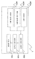
도 1은 본 발명의 이상 검출 장치의 시스템 전체의 구성도를 도시하는 도면이다.
도 2는 본 발명이 적용되는 건설 기계인 유압 셔블의 전체 구성을 도시하는 도면이다.
도 3은 본 발명이 적용되는 건설 기계(유압 셔블)의 유압 시스템을 도시하는 도면이다.
도 4는 본 발명의 제1 실시예의 이상 검출 장치의 시스템 전체의 구성도로, 도 1의 센서를 펌프 케이스 드레인 압력 센서로 치환한 것이다.
도 5는 제1 실시예에서 정상 상태의 펌프 압력을 계측한 결과를 나타내는 도면이다.
도 6은 제1 실시예에서 정상 상태에서의 상관 계수를 산출한 결과를 나타내는 도면이다.
도 7은 제1 실시예의 유압 펌프의 정상시에 있어서의 상관 계수에 대응하는 정규화한 편차를 나타내는 도면이다.
도 8은 제1 실시예의 정상 상태에서의 상관 계수 비교부의 출력을 나타내는 도면이다.
도 9는 제1 실시예에서 이상이 발생하였을 때의 펌프 압력을 계측한 결과를 나타내는 도면이다.
도 10은 제1 실시예에서 이상이 발생하였을 때의 상관 계수를 산출한 결과를 나타내는 도면이다.
도 11은 제10 실시예의 유압 펌프의 이상시에 있어서의 상관 계수에 대응하는 정규화한 편차를 나타내는 도면이다.
도 12는 제1 실시예에서 이상이 발생하였을 때의 상관 계수 비교부의 출력을 나타내는 도면이다.
도 13은 본 발명의 제2 실시예의 시스템 전체의 구성도이다.
도 14는 본 발명의 제3 실시예의 시스템 전체의 구성도이다.
도 15는 제3 실시예의 엔진 기통 온도를 나타내는 도면이다.
도 16은 제3 실시예에서 이상이 발생하였을 때의 상관 계수를 산출한 결과를 나타내는 도면이다.
도 17은 제3 실시예에서 이상이 발생하였을 때의 상관 계수 비교부의 출력을 나타내는 도면이다.
도 18은 본 발명의 제4 실시예의 시스템 전체의 구성도이다.
도 19는 본 발명의 제5 실시예의 시스템 전체의 구성도이다.
도 20은 제5 실시예에서 이상이 발생하였을 때의 상관 계수를 산출한 결과를 나타내는 도면이다.
도 21은 제5 실시예에서 이상이 발생하였을 때의 상관 계수 비교부의 출력을 나타내는 도면이다.
도 22는 도 3에 도시한 유압 시스템에 작동유 냉각 장치를 설치한 경우의 구성을 도시하는 도면이다.
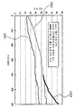
도 23은 작동유 냉각 장치에 있어서의 릴리프 밸브가 정상시의 온도 변화와 릴리프 밸브가 고장시의 온도 변화를 나타내는 도면이다.
도 24는 본 발명의 제6 실시예의 시스템 전체의 구성도이다.
도 25는 유압 셔블의 엔진 오일 냉각 계통 및 냉각수 냉각 계통의 구성을 도시하는 도면이다.
도 26은 엔진 회전수, 엔진 오일 압력, 냉각수 압력의 시계열 변화를 나타내는 도면이다.
도 27은 본 발명의 제7 실시예의 시스템 전체의 구성도이다.
도 28은 라디에이터 입구 냉각수 온도 Tr과 엔진 오일 온도 Te의 시계열 변화를 나타내는 도면이다.
도 29는 본 발명의 제8 실시예의 시스템 전체의 구성도이다.BRIEF DESCRIPTION OF THE DRAWINGS It is a figure which shows the block diagram of the whole system of the abnormality detection apparatus of this invention.
It is a figure which shows the whole structure of the hydraulic excavator which is a construction machine to which this invention is applied.
3 is a view showing a hydraulic system of a construction machine (hydraulic shovel) to which the present invention is applied.
4 is a configuration diagram of the entire system of the abnormality detecting device of the first embodiment of the present invention, in which the sensor of FIG. 1 is replaced with a pump case drain pressure sensor.
FIG. 5 is a diagram showing a result of measuring a pump pressure in a steady state in the first embodiment. FIG.
FIG. 6 is a diagram showing a result of calculating a correlation coefficient in a steady state in the first embodiment. FIG.
It is a figure which shows the normalized deviation corresponding to the correlation coefficient in the normal state of the hydraulic pump of 1st Example.
Fig. 8 is a diagram showing the output of the correlation coefficient comparing unit in the steady state of the first embodiment.
FIG. 9 is a diagram showing a result of measuring a pump pressure when an abnormality occurred in the first embodiment. FIG.
10 is a diagram illustrating a result of calculating a correlation coefficient when an abnormality occurs in the first embodiment.
It is a figure which shows the normalized deviation corresponding to the correlation coefficient at the time of abnormality of the hydraulic pump of 10th Example.
12 is a diagram showing an output of the correlation coefficient comparison unit when an abnormality occurs in the first embodiment.
Fig. 13 is a configuration diagram of the whole system of the second embodiment of the present invention.
14 is a configuration diagram of the whole system of the third embodiment of the present invention.
Fig. 15 is a diagram showing the engine cylinder temperature in the third embodiment.
FIG. 16 is a diagram illustrating a result of calculating a correlation coefficient when an abnormality occurs in the third embodiment. FIG.
FIG. 17 is a diagram showing an output of the correlation coefficient comparison unit when an abnormality occurs in the third embodiment. FIG.
18 is a configuration diagram of the whole system of the fourth embodiment of the present invention.
19 is a configuration diagram of the whole system of the fifth embodiment of the present invention.
20 is a diagram illustrating a result of calculating a correlation coefficient when an abnormality occurs in the fifth embodiment.
21 is a diagram illustrating an output of the correlation coefficient comparison unit when an abnormality occurs in the fifth embodiment.
It is a figure which shows the structure at the time of installing the hydraulic fluid cooling device in the hydraulic system shown in FIG.
It is a figure which shows the temperature change at the time of relief valve normal in a hydraulic fluid cooling device, and the temperature change at the time of relief valve failure.
24 is a configuration diagram of the whole system of the sixth embodiment of the present invention.
It is a figure which shows the structure of the engine oil cooling system and cooling water cooling system of a hydraulic excavator.
It is a figure which shows the time-series change of engine speed, engine oil pressure, and cooling water pressure.
27 is a configuration diagram of the whole system of the seventh embodiment of the present invention.
It is a figure which shows the time-series change of radiator inlet cooling water temperature Tr and engine oil temperature Te.
29 is a configuration diagram of the whole system of the eighth embodiment of the present invention.
이하, 본 발명의 실시예를 도면을 사용하여 설명한다.Best Mode for Carrying Out the Invention Embodiments of the present invention will now be described with reference to the drawings.
제1 실시예First embodiment
[펌프의 사례 (1)에 대해][About Pump Case (1)]
본 발명의 일 실시예에 대해, 건설 기계인 유압 셔블을 예로 들어, 도 1 내지 도 12를 사용하여 설명한다. 본 실시예는, 복수의 센서가 복수의 관련되는 물리 상태로서 3개 이상의 동일한 물리 상태를 검출하는 경우의 것이다. 또한, 본 발명은 유압 셔블에 한정되지 않고, 크레인차, 휠 로더, 불도저 등의 그 밖의 건설 기계에도 적용 가능하다.An embodiment of the present invention will be described with reference to FIGS. 1 to 12 by taking a hydraulic excavator which is a construction machine as an example. This embodiment is a case where a plurality of sensors detect three or more identical physical states as a plurality of related physical states. Moreover, this invention is not limited to a hydraulic excavator, but is applicable also to other construction machines, such as a crane car, a wheel loader, a bulldozer, etc.
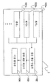
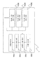
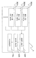
도 1은 본 발명의 이상 검출 장치의 시스템 전체의 구성도를 도시한 것이다.1 is a block diagram of the entire system of the abnormality detecting device of the present invention.
본 발명의 이상 검출 장치(1)는 복수의 센서(101a, 101b, 101c, …)를 구비한 구성을 도시하고 있다. 그리고 이들 복수의 센서(101a, 101b, 101c, …)(이하, 적절하게 101로 대표함)로부터의 센서 신호(센서 정보)를 도시하지 않은 A/D 변환부를 통해 상관 계수 산출부(102)에 입력한다. 상관 계수 산출부(102)에서는, 소정의 동일 기간의 복수(3개 이상)의 센서 신호를 입력하고, 그 센서 신호에 시각 정보를 부가하여 동일 기간에 있어서의 복수(3개 이상)의 시계열적 물리 상태 정보를 생성하고, 그 시계열적 물리 상태 정보인 복수의 센서 신호의 시계열값에 대해 서로의 상관 계수를 산출한다. 그리고 이들 상관 계수는 상관 계수 비교부(103)에 입력되고, 상관 계수 비교부(103)는 상관 계수에 기초하여 정규화한 편차를 산출한다. 상관 계수로부터 정규화한 편차를 산출하는 수순에 대해서는 후술하지만, 개요로서는 산출한 상관 계수로부터 그 평균값과 표준 편차를 사용하여 편차의 정규화를 행한다. 그 후, 구한 정규화한 편차의 절대값에 따른 정규화한 편차를 상관 비교값으로서 치환하여, 각 상관 계수마다 이들의 상관 비교값의 합계값을 산출하여 상관 비교 합계값을 구한다. 상관 계수 비교부(103)는, 이 상관 비교 합계값의 백분율을 출력으로 하여, 이상 판정부(104)에 전달한다.The
이상 판정부(104)에서는, 예를 들어 상관 비교 합계값의 백분율이 50% 이상에 대해서는, 「경고 판정」, 80% 이상에 대해서는, 「이상 판정」을 출력하도록 구성한다.The
또한, 도 2는 본 발명의 이상 검출 장치의 시스템 전체를 탑재한, 건설 기계의 전체 구성도를 도시하는 것이다.2 shows the whole block diagram of the construction machine which mounted the whole system of the abnormality detection apparatus of this invention.
도 2를 사용하여 건설 기계인 유압 셔블(852)의 동작에 대해 설명한다. 유압 셔블(852)은, 구비된 각 조작 기구에 의해 굴삭 등의 동작을 행할 수 있다. 버킷(861), 아암(862), 붐(863)은, 유압 실린더(871, 872, 873)에 의해 구동된다. 이들 굴삭에 관한 부위 전체는 프론트라 불리는 경우가 많다. 유압 실린더(871, 872, 873)가 신축 동작을 함으로써, 버킷(861), 아암(862), 붐(863) 등이 동작한다. 붐(863)의 기단부는 상부 선회체(856)의 전방부에 회전 가능하게 장착되어 있다. 상부 선회체(856)는, 선회 기구(854)를 통해 하부 주행체(855) 상을 선회 가능하다.The operation of the
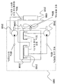
또한, 도 3에 유압 실린더(871, 872, 873)의 유압을 발생시키는 유압 시스템의 구성을 도시한다.3, the structure of the hydraulic system which generate | occur | produces the hydraulic pressure of the
도 3에 있어서, 엔진(902)으로부터의 토크에 의해 유압 펌프(904)가 구동된다. 이에 의해 탱크(940)에 수납되어 있는 오일이 유압을 제어하는 컨트롤 밸브(906)로 보내지게 된다. 컨트롤 밸브(906)는 외부로부터 조작 기구 및 제어 장치(여기서는 도시하지 않음)에 의해 제어되고, 예를 들어 유압 실린더(871, 872, 873) 등을 가동시켜, 버킷(861), 아암(862), 붐(863)을 움직이는 유압을 발생시킨다. 또한, 컨트롤 밸브(906)로부터 제어에 수반하여 불필요해지는 오일에 대해서는 탱크(942)로 배출되도록 되어 있다.In FIG. 3, the
그리고 이 실시예에서는 유압 펌프(904)에 후술하는 펌프 케이스 드레인 압력 센서(201)가 설치되어 있고, 또한 엔진(902)에도 엔진 기통 온도 센서(301)가 설치되어 있다.In this embodiment, the pump case
엔진(902)에 의해 구동되는 유압 펌프(904)는 복수개, 예를 들어 5개 있고, 그것에 따라서 펌프 케이스 드레인 압력 센서(201)도 복수개, 예를 들어 5개 있다. 이하에 있어서, 복수개의 유압 펌프 및 압력 센서를 각각 1개의 부호로 대표하여 설명하는 경우는 부호 904, 201을 사용하고, 개별의 유압 펌프 및 압력 센서를 나타내는 경우에는, 첨자 a, b, c, …를 부여한 부호 904a, 904b, 904c, … 및 201a, 201b, 201c, …를 사용하여 설명한다.There are a plurality, for example, five
유압 셔블(852)의 엔진(902)에는 복수개, 예를 들어 16개의 기통이 구비되어 있고, 그것에 따라서 엔진 기통 온도 센서(301)도 복수개, 예를 들어 19개 있다. 이하에 있어서, 엔진 기통 온도 센서를 1개의 부호로 대표하여 설명하는 경우에는 부호 301을 사용하고, 개별의 엔진 기통 온도 센서를 나타내는 경우는, 첨자 a, b, c, …를 부여한 부호 301a, 301b, 301c, …를 사용하여 설명한다.The
유압 셔블(852)의 상부 선회체(856)의 캡(856a) 내에는 모니터에 접속된 컨트롤러(856b)가 배치되어 있고, 상술한 A/D 변환부(도시하지 않음), 상관 계수 산출부(102), 상관 계수 비교부(103), 이상 판정부(104)는 그 컨트롤러(856b)에 의해 구성되어 있다. 또한, 컨트롤러(856b)는 관리실 등에 별도 배치로 하고, 유압 셔블(852)에서는 센서에 의해 검출된 데이터를 일단 데이터베이스에 보존하고, 그 데이터를 정기적으로 취출하여 컨트롤러로 송신 혹은 다운로드해도 된다.The controller 856b connected to the monitor is disposed in the cap 856a of the
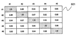
도 4는 도 1에 있어서의 센서(101)를 펌프 케이스 드레인 압력 센서(201)로 치환한 것으로, 전술한 건설 기계(852)에 사용되고 있는 것이다. 유압 펌프(904)는, 전달하는 압력을 조정하는 중요한 부품이다. 펌프 케이스 드레인 압력 센서(201)를 사용하여, 건설 기계(852)가 정상적으로 운전 동작하고 있을 때의 정상 상태의 펌프 내의 압력을 계측한 결과를 도 5에 나타낸다. 측정한 경과 시간대에 있어서 펌프 내의 압력은 돌출된 높은 압력이 발생되어 있지 않은 것을 나타내고 있다. 여기서는, 펌프 케이스 드레인 압력 센서(201)는 펌프 케이스 드레인 압력 센서(201a 내지 201e)(도시하지 않음)까지의 5개의 펌프(904a 내지 904e)에 대해 계측하고 있는 것으로 한다. 상관 계수 산출부(102)에서는, 동일 기간의 복수의 센서 신호를 시계열적으로 입력하고, 동일 기간에 있어서의 5개의 시계열적인 압력 정보를 생성하고, 이들 압력 정보의 시계열값에 대해, 상관 계수 산출부(102)를 사용하여 서로의 상관 계수를 산출한다. 그 결과를 도 6의 표 601에 나타낸다. 상관 계수의 산출 방법은, 이하의 수학식 1과 같다.FIG. 4 replaces the sensor 101 in FIG. 1 with the pump case
입력값[여기서는 펌프 케이스 드레인 압력 센서(201)를 사용하여 측정된 드레인 압력값] 중, 임의의 2개의 입력값을 Xi와 Xj(i, j=1, …, n)(n은 입력값으로 되는 센서의 수, 본 실시예에서는 5)로 하고, Xi, Xj의 시각 t의 계측값을 Xi(t), Xj(t)로 나타내는 것으로 하고, 시각 t=0으로부터 시각 t=T-1까지의 계측값에 대해 산출하면, 입력값 Xi와 Xj의 상관 계수 ρ(i, j)는, 평균 μi, μj와 표준 편차 σi, σj를 사용하여 하기의 식으로 산출된다.Among the input values (here, the drain pressure values measured using the pump case drain pressure sensor 201), any two input values are Xi and Xj (i, j = 1, ..., n) (n is an input value. In the present embodiment, the number of sensors to be used is 5), and the measured values of time t of Xi and Xj are represented by Xi (t) and Xj (t), and from time t = 0 to time t = T-1 When calculated | required about the measured value of, the correlation coefficient (rho (i, j)) of input value Xi and Xj is computed by the following formula using average (micro) i, (microj), and standard deviation (sigma) i, (sigma) j.

상관 계수는, -1로부터 1까지의 값을 취하고, 도 6에 나타낸 값은 모두 1에 가까운 값을 나타내고 있어(동일한 값끼리의 상관이 1인 것은 당연함), 강한 상관이 있는 것을 알 수 있다.The correlation coefficient takes a value from -1 to 1, and all the values shown in FIG. 6 represent values close to 1 (it is obvious that the correlations between the same values are 1), and it is understood that there is a strong correlation. .
상관 계수 비교부(103)는, 표 401에 나타낸 상관 계수에 기초하여 정규화한 편차를 산출한다. 상관 계수로부터 정규화한 편차를 산출하는 수순에 대해서는, 후술한다. 상관 계수에 기초하여 산출된 정규화한 편차를 도 7의 표 701에 나타낸다. 상관 계수 비교부(103)는, 이 편차를 사용하여, 편차의 절대값이 3.0 이상일 때에는 1.0, 3.0 미만 1.5 이상일 때에는 0.5, 1.5 미만일 때에는 0의 상관 비교값으로서 치환한다. 이 결과가 도 8에 나타낸 표 801이다. 상관 비교값 1.0, 0, 5, 0은 이상 플래그 정보로서 사전에 정한 값이다. 상관 계수 비교부(103)는, 마지막으로 이들 합계값을 각 상관 계수에 대해 산출하고, 도 8의 표 802에 나타내는 상관 비교 합계값을 산출하고, 이것을 백분율로서 산출한다. 상관 비교 합계값 혹은 그 백분율은 상관 비교값을 집계하여 얻은 각 상관 계수의 다른 상관 계수에 대한 차이의 정도를 나타내는 값이다. 상관 비교 합계값이 50% 미만인 경우에는, 정상이라고 판정된다. 상관 비교 합계값으로부터 직접 이상을 판정해도 된다.The correlation
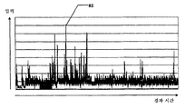
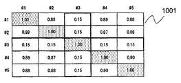
다음에, 도 9에 이상이 발생하였을 때의 펌프 압력을 계측한 결과를 나타낸다. 도 9에서 알 수 있는 바와 같이, #3의 펌프의 압력이 높아져 있다. 이때의 상관 계수를 상관 계수 산출부(102)를 사용하여 산출하면, 도 10의 표 1001에 나타내는 바와 같이 된다. #3 이외의 상관 계수에 큰 변화는 나타나 있지 않지만, #3의 상관 계수가 작아져 있는 것을 알 수 있다. 즉, #3의 펌프는 다른 펌프의 움직임과는 다른 경향을 나타내고 있는 것을 나타내고 있다. 이 상관 계수에 관하여, 상관 계수 비교부(103)를 사용하여, 상관 계수의 변화, 즉 정규화한 편차를 검출한다. 예를 들어, 도 10의 표 1001에 있어서, #1로부터 본 각 펌프의 상관 계수는, 1.00, 0.88, 0.15, 0.89, 0.88이다. 상관 계수 비교부(103)에서는, 이들 상관 계수 ρ(1, j)(j=1, …, 5)에 대해, 그 평균 μ(ρ1)과 표준 편차 σ(ρ1)를 사용하여 정규화를 행한다. 정규화한 값을 ρs(1, j)(j=1, … , 5)로 하면,Next, the result of having measured the pump pressure at the time of abnormality in FIG. 9 is shown. As can be seen from FIG. 9, the pressure of the pump of # 3 is increased. If the correlation coefficient at this time is computed using the correlation
![]()
![]()
로 되고, #1의 펌프의 상관 계수 1.00, 0.88, 0.15, 0.89, 0.88에 대응하는 정규화한 편차는, 각각 도 11의 표 1101에 나타낸 바와 같이 0.70, 0.35, -1.77, 0.38, 0.35로 된다. 수학식 2를 #1 내지 #5 전체에 대해 일반화하면, 수학식 3와 같이 된다.Normalized deviations corresponding to the correlation coefficients 1.00, 0.88, 0.15, 0.89, and 0.88 of the pump of # 1 are 0.70, 0.35, -1.77, 0.38, and 0.35, respectively, as shown in Table 1101 of FIG. If

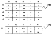
상관 계수 비교부(103)는, 이 편차를 사용하여, 편차의 절대값이 3 이상일 때에는 1.0, 3 미만 1.5 이상일 때에는 0.5, 1.5 미만일 때에는 0의 상관 비교값으로서 치환한다. 이 결과가 도 12에 나타낸 표 1201이다. 상관 계수 비교부(103)에서는, 마지막으로 이들의 합계값을 각 상관 계수에 대해 산출한다. 도 12의 표 1202에 나타내는 바와 같이, #1 내지 #5까지의 펌프 압력에 대한 상관 비교 합계값은, 각각 0, 0, 2.5, 0, 0으로 되고, 이것을 백분율로 나타내면, 0%, 0%, 50%, 0%, 0%로 된다. 상관 계수 비교부(103)는, 이 상관 비교 합계값의 백분율을 출력으로 하여, 이상 판정부(104)에 전달한다.The correlation
이상 판정부(104)에서는, 상관 비교 합계값의 백분율이 50% 이상에 대해서는, 「경고 판정」, 80% 이상에 대해서는, 「이상 판정」을 출력한다. 도 12의 예에서는, 이상 판정부(104)에 의한 판정 결과는, #3의 펌프에 대해 「경고 판정」을 출력하게 된다. 「이상 판정」의 출력 방법으로서는, 예를 들어 「경고 판정」 혹은 「이상 판정」의 문자를 모니터에 표시한다.The
본 실시예에 따르면, 유압 펌프의 제어 상태에 따라서 복수의 압력 센서로부터 얻은 센서 정보의 상관 계수의 비교 정보에 의해 이상 검출을 행하기 때문에, 미리 유압 셔블의 상태에 따른 판정 임계값이나 학습값을 계측 데이터로부터 산출할 필요가 없으므로, 유압 셔블의 다른 사용 환경이나 운용 형태에 있어서, 동일한 판정 방법에 따라 기계에 적절한 판정을 행하여, 기계의 고장을 미연에 방지할 수 있다.According to this embodiment, since abnormality is detected by comparison information of correlation coefficients of sensor information obtained from a plurality of pressure sensors according to the control state of the hydraulic pump, the determination threshold value or learning value according to the state of the hydraulic excavator is previously determined. Since it is not necessary to calculate from the measurement data, it is possible to make an appropriate judgment on the machine according to the same determination method in another use environment and operation mode of the hydraulic excavator, thereby preventing the failure of the machine in advance.
제2 실시예Second embodiment
[펌프의 사례 (2)에 대해][About pump case 2]
본 발명의 다른 실시예를 상술한 실시예 및 도 13을 사용하여 설명한다. 본 실시예는 제1 실시예의 변형예이다.Another embodiment of the present invention will be described using the above-described embodiment and FIG. This embodiment is a modification of the first embodiment.
도 13에 있어서, 본 실시예에 있어서의 이상 검출 장치(1)는, 도 2에 도시한 구성에 더하여, 유압 셔블(852)(도 18 참조)의 조작 정보를 검출하는 조작 정보 검출부(202)와, 그 조작 정보에 기초하여 각 유압 펌프(904)의 동작 상태를 판정하는 펌프 동작 판정부(203)를 더 구비하고 있다. 유압 셔블(852)은, 조작 기구로서, 레버 조작량에 따른 조작 파일럿압을 생성하고, 그 조작 파일럿압에 의해 컨트롤 밸브(906)를 구동하는 컨트롤 레버 장치를 구비하고 있다. 조작 정보 검출부(202)는, 예를 들어 그 조작 파일럿압을 검출하는 압력 센서이다. 그 경우, 펌프 동작 판정부(203)는 조작 파일럿압이 일정값을 초과하면, 그 조작 파일럿압에 의해 구동되는 컨트롤 밸브(906)에 영향을 미치는 유압 펌프(904)는 동작 상태에 있다고 판정한다.In FIG. 13, in addition to the configuration shown in FIG. 2, the
상관 계수 산출부(102)는, 펌프 동작 판정부(203)의 판정 결과에 기초하여, 동작하고 있는 유압 펌프(904)만의 압력 정보를 사용하여 상관 계수를 산출한다.The correlation
본 실시 형태에 따르면, 동작하고 있지 않은 유압 펌프는 진단으로부터 제외되므로, 보다 정확한 이상 검출을 할 수 있다.According to this embodiment, since the hydraulic pump which is not operating is excluded from diagnosis, more accurate abnormality detection can be performed.
제3 실시예Third embodiment
[엔진의 사례 (1)에 대해][About engine case (1)]
본 발명의 또 다른 실시예에 대해, 건설 기계인 유압 셔블을 예로 들어, 상술한 실시예 및 도 14 내지 도 17을 사용하여 설명한다. 본 실시예도, 복수의 센서가 복수의 관련되는 물리 상태로서 3개 이상의 동일한 물리 상태를 검출하는 경우의 것이다.Another embodiment of the present invention will be described using the above-described embodiment and FIGS. 14 to 17 by taking a hydraulic excavator as a construction machine as an example. This embodiment is also a case where a plurality of sensors detect three or more identical physical states as a plurality of related physical states.
도 14는, 도 1에 있어서의 센서(101)를 엔진 기통 온도 센서(301)로 치환한 것이다. 전술한 바와 같이, 유압 셔블(852)의 엔진(902)에는 16개의 기통이 구비되어 있고, 엔진 기통 온도 센서(301a 내지 301p)(도시하지 않음)까지의 16개의 엔진 기통 온도 센서에 의해 각 기통의 온도가 측정되어, 엔진의 동작 상태를 알 수 있다.FIG. 14 replaces the sensor 101 in FIG. 1 with the engine
도 15는 이상 상태로서, 예를 들어 엔진 기통에 연료를 공급하는 인젝션 기구에 이상이 발생하여, 연료가 공급 과다로 되었을 때의 엔진 기통 온도 센서(301a) 내지 엔진 기통 온도 센서(301p)에 의해 측정된 엔진 기통 온도를 나타낸 것이다. 도 15로부터, #3의 기통 온도는 다른 기통 온도에 비교하여 높고, #4와 #9의 기통 온도는 다른 기통 온도와는 다른 변화를 나타내고 있다. 이들 기통 온도에 대해, 상술한 제1 실시예와 마찬가지로, 상관 계수 산출부(102)에 의해 상관 계수가 산출된 결과를 도 16에 나타낸다. 그리고 이것을 상관 계수 비교부(103)에 의해 비교한 결과를 도 17에 나타낸다. 상관 비교 합계값의 백분율은, #4의 엔진이 41%, #9의 엔진이 94%이다. 이것을 이상 판정부(104)에 의해 판정하면, #9의 엔진만이「이상 판정」으로서 출력된다(#4의 엔진은 41%이므로, 「경고 판정」의 50%에는 달하지 않음).15 is an abnormal state, for example, by an engine
제4 실시예Fourth Embodiment
[엔진의 사례 (2)에 대해][About engine case (2)]
본 발명의 또 다른 실시예를 상술한 실시예 및 도 18을 사용하여 설명한다. 본 실시예는 제3 실시예의 변형예이다.Another embodiment of the present invention will be described using the above-described embodiment and FIG. 18. This embodiment is a modification of the third embodiment.
도 18에 있어서, 본 실시예에 있어서의 이상 검출 장치(1)는, 도 14에 나타낸 구성에 더하여, 엔진(902)(도 3 참조)의 회전수를 검출하는 회전수 센서(302)를 더 구비하고 있다.In FIG. 18, in addition to the configuration shown in FIG. 14, the
상관 계수 산출부(102)는, 회전수 센서(302)에 의해 검출된 엔진 회전수가 소정의 값 이상인 경우만의 온도 정보를 사용하여 상관 계수를 산출한다.The correlation
본 실시 형태에 따르면, 엔진(902)이 소정치 미만의 회전수로 동작하고 있을 때의 온도 정보는 진단으로부터 제외되므로, 보다 정확한 이상 검출을 할 수 있다.According to this embodiment, since the temperature information when the
제5 실시예Fifth Embodiment
[엔진의 사례 (3)에 대해][About engine case (3)]
본 발명의 또 다른 실시예에 대해, 건설 기계인 유압 셔블을 예로 들어, 상술한 실시예 및 도 19 내지 도 21을 사용하여 설명한다. 본 실시예도, 복수의 센서가 복수의 관련되는 물리 상태로서 3개 이상의 동일한 물리 상태를 검출하는 경우의 것이다.Another embodiment of the present invention will be described using the above-described embodiment and FIGS. 19 to 21 by taking a hydraulic excavator as a construction machine as an example. This embodiment is also a case where a plurality of sensors detect three or more identical physical states as a plurality of related physical states.
제3 실시예에서는, #9의 엔진에 이상이 있는 것을 판정하여, #4의 엔진에 있어서는 그 징후가 있는 것을 알 수 있었지만, #3의 엔진의 이상은 판정할 수 없었다. 이것은, #3의 엔진에 대해서는, 온도 범위가 다른 기통과 다르지만, 변화의 방식은 다른 기통과 동일한 것이었기 때문이다.In the third embodiment, it was determined that there was an abnormality in the engine of # 9, and it was found that there was a symptom in the engine of # 4, but the abnormality of the engine of # 3 could not be determined. This is because, for the engine of # 3, the temperature range is different from the other cylinders, but the mode of change was the same as the other cylinders.
이로 인해, 본 실시예는 #3의 엔진과 같은 이상을 검출하는 것을 나타낸 것이다.For this reason, this embodiment shows detecting abnormality like the engine of # 3.
도 19에, 본 실시예의 구성을 도시한다. 제3 실시예의 도 14의 구성에 있어서의 상관 계수 산출부(102) 및 상관 계수 비교부(103) 대신으로서, 상대비 산출부(402) 및 상대비 비교부(403)를 구비한 구성으로 되어 있다.19 shows the configuration of this embodiment. Instead of the correlation
입력값[여기서는 엔진 기통 온도 센서(301)를 사용하여 측정된 기통 온도] 중, 임의의 2개의 입력값을 Xi와 Xj(i, j=1, …, n)(n은 입력값으로 되는 센서의 수, 본 실시예에서는 16)로 하고, Xi, Xj의 시각 t의 계측값을 Xi(t), Xj(t)로 나타내는 것으로 하고, 시각 t=0으로부터 시각 t=T-1까지의 계측값에 대해 산출하면, 입력값 Xi에 대한 Xj의 상대비 ν(i, j)는, 하기의 식으로 산출된다.Among the input values (in this case, the cylinder temperature measured using the engine cylinder temperature sensor 301), any two input values are defined as Xi and Xj (i, j = 1, ..., n) (n is a sensor that becomes an input value). In the present embodiment, the measurement value of time t of Xi and Xj is represented by Xi (t) and Xj (t), and measurement from time t = 0 to time t = T-1 When it calculates about a value, the relative ratio (nu, i, j) of Xj with respect to input value Xi is computed with the following formula.
![]()
![]()
상대비 산출부(402)를 사용하여, 엔진 기통 온도의 상대비를 산출하면, 도 20의 표에 나타내는 결과로 된다. 그리고 상대비 비교부(403)를 사용하여 상대비 비교 합계값 및 그 백분율을 산출하면, 도 21과 같이 된다. 이 상대비 비교 합계값의 산출 방법은, 상술한 제3 실시예에 있어서의 상관 계수를 상대비로 치환하여 산출한 것이다. 도 21에 나타내는 바와 같이, 상대비 비교 합계값의 백분율이, 상대비 산출부(402)로부터 이상 판정부(104)에 출력되고, 이상 판정부(104)에 의해, 「이상 판정」이 출력되게 된다.When the relative ratio of the engine cylinder temperature is calculated using the relative
또한, 본 실시예는 제3 실시예의 일부를 변경하는 것으로 하여 설명하였지만, 다른 실시예에 대해서도 마찬가지로 본 실시예의 생각을 적용할 수 있는 것이다.Incidentally, the present embodiment has been described by changing a part of the third embodiment, but the idea of the present embodiment can be similarly applied to other embodiments.
제6 실시예Sixth embodiment
(작동유 냉각 장치의 사례)(Example of working oil cooling unit)
본 발명의 또 다른 실시예에 대해, 건설 기계인 유압 셔블을 예로 들어, 상술한 실시예 및 도 22 내지 도 24를 사용하여 설명한다. 본 실시예는, 복수의 센서가 복수의 관련되는 물리 상태로서 2개 이상의 관련되어 변화되는 물리 상태를 검출하는 경우의 것이다.Another embodiment of the present invention will be described using the above-described embodiment and FIGS. 22 to 24 by taking a hydraulic excavator which is a construction machine as an example. This embodiment is a case where a plurality of sensors detects two or more associated and changed physical states as a plurality of related physical states.
도 22는 도 3에 도시한 유압 시스템에 작동유 냉각 장치를 설치한 경우의 구성을 도시하는 도면이다.It is a figure which shows the structure at the time of installing the hydraulic fluid cooling device in the hydraulic system shown in FIG.
도 22에 있어서, 전술한 바와 같이, 엔진(902)에 의해 발생된 운동 에너지는, 유압 펌프(904)를 구동하여, 작동유 탱크(940)로부터 작동유를 퍼올려, 컨트롤 밸브(906)를 경유하여 유압 실린더(871, 872, 873) 등으로 보내고, 유압 실린더(871, 872, 873) 등을 가동시켜, 버킷(861), 아암(862), 붐(863)을 움직이는 유압을 발생시킨다.In FIG. 22, as described above, the kinetic energy generated by the
유압 실린더(871, 872, 873) 등이 신축하는 데 수반하여, 작동유가 작동유 탱크(940)로 복귀된다. 작동유는 유압 실린더(871, 872, 873) 등을 구동할 때에 그 압력에 의해 온도 상승하므로, 작동유 탱크(940)로 복귀시키기 전에 작동유 쿨러(1904)를 통해 냉각된다. 작동유 쿨러(1904)는, 엔진(902)에 접속된 냉각 팬(1908)을 회전시켜, 외기를 흡입함으로써 냉각되고, 그것에 의해 작동유가 냉각되어 작동유 탱크(940)로 복귀된다. 릴리프 밸브(1905)는, 컨트롤 밸브(906)로부터 복귀된 작동유의 압력이 높음으로써, 작동유 쿨러(1904)가 파괴되지 않도록 하기 위한 안전 밸브이다. 릴리프 밸브(1905)는 필요에 따라서 개방되도록 되어 있고, 릴리프 밸브(1905)가 고장나면, 각 부의 압력이나 온도에 이상이 발생한다.As the
작동유 쿨러(1904)는, 외기온에 의해 냉각되므로, 외기 온도 Ta가 상승하는 것에 수반하여, 작동유 온도 To, 쿨러 입구 온도 Tin, 쿨러 출구 온도 Tout도 상승하게 된다.Since the
도 23에 릴리프 밸브(1905) 정상시의 온도 변화 2001과 릴리프 밸브(1905) 고장시의 온도 변화 2002를 나타낸다.23 shows the
릴리프 밸브(1905)가 고장나, 개방된 상태인 채로 된 경우를 생각한다. 릴리프 밸브(1905)가 개방된 채로 되어 있으므로, 작동유 쿨러(1904)로 유입되는 작동유가 감소하므로, 작동유가 충분히 냉각되지 않는다고 하는 상태로 된다. 온도 변화 2002에 나타내는 바와 같이, 쿨러 출구 온도 Tout는, 작동유 쿨러(1904)에 유입되는 작동유가 감소하는 만큼 온도가 내려가지만, 작동유 쿨러(1904)에 유입되지 않는 작동유가 증가하는 만큼 작동유 온도 To는 상승한다. 결과적으로, 작동유 쿨러 입구 온도 Tin도 상승하게 된다.Consider a case where the
본 실시예의 이상 검출 장치는, 상기 외기 온도 Ta, 작동유 온도 To, 쿨러 입구 온도 Tin, 쿨러 출구 온도 Tout를 각각 온도 센서(501a, 501b, 501c, 501d)에 의해 검출하고, 그 센서값을 입력으로서, 정상 동작시의 상관 계수를 기준으로 하여, 이상 동작시의 상관 계수의 변화를 검출한다. 이에 의해 작동유 냉각 장치의 이상[상기한 예에서는 릴리프 밸브(1905)의 고장]을 검출할 수 있다.The abnormality detecting device of the present embodiment detects the outside air temperature Ta, the hydraulic oil temperature To, the cooler inlet temperature Tin, and the cooler outlet temperature Tout by the
여기서, 본 실시예에서는, 정상 동작시의 상관 계수를 얻기 위해 다른 기간의 상관 계수를 이용한다.Here, in this embodiment, correlation coefficients of different periods are used to obtain correlation coefficients in normal operation.
즉, 도 23에 있어서, 다른 기간 A, B, C를 생각한다. 기간 A는 릴리프 밸브(1905) 고장 직후의 기간이다. 기간 B는 릴리프 밸브(1905) 고장 직전의 기간이다. 기간 C는 기간 B 전의 기간이다. 기간 B와 기간 C에서는, 외기 온도 Ta가 상승하는 것에 수반하여, 작동유 온도 To, 쿨러 입구 온도 Tin, 쿨러 출구 온도 Tout가 상승하고 있다. 따라서, 기간 B와 기간 C의 센서값을 사용하여 기간 B와 기간 C의 각각에 있어서 상관 계수를 산출하고, 그 상관 계수와 기간 A의 센서값을 사용하여 산출한 상관 계수를 비교함으로써, 기간 A에서 무언가의 이상이 발생한 것을 검지할 수 있다.That is, in FIG. 23, another period A, B, and C are considered. Period A is a period immediately after the
또한, 기간 A에 있어서의 상관 계수로부터, 쿨러 출구 온도 Tout가 쿨러 입구 온도 Tin 및 작동유 온도 To와는 외기 온도 Ta에 대해 다른 변화를 하고 있는 것을 알 수 있고, 온도 센서(401d)에 관계되는 부위에 이상이 발생하였다고 판정할 수 있어, 릴리프 밸브(1905)에 고장이 발생한 것을 추정할 수 있다.From the correlation coefficient in the period A, it can be seen that the cooler outlet temperature Tout is different from the cooler inlet temperature Tin and the hydraulic oil temperature To with respect to the outside temperature Ta, and thus, at the site related to the temperature sensor 401d. It can be determined that an abnormality has occurred, and it can be estimated that a failure has occurred in the
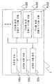
도 24는 본 실시예에 있어서의 이상 검출 장치(1)의 구성을 도시하는 도면이다. 본 실시예에 있어서의 이상 검출 장치(1)는, 도 1에 있어서의 센서(101)를 온도 센서(501a, 501b, 501c, 501d)로 치환하고, 상관 계수 산출부(102)를 상관 계수 산출부(502)로 치환한 것이다.24 is a diagram illustrating the configuration of the
온도 센서(501a, 501b, 501c, 501d)는, 각각 상기 외기 온도 Ta, 작동유 온도 To, 쿨러 입구 온도 Tin, 쿨러 출구 온도 Tout를 검출한다.The
상관 계수 산출부(502)는, 온도 센서(501a, 501b, 501c, 501d)로부터 출력되는 센서 신호를 3개 이상의 다른 소정 기간(상기한 예에서는 기간 A, B, C)의 각각에 있어서 입력하고, 센서마다 동일 기간에 있어서의 3개 이상의 시계열적 물리 상태 정보(상기한 예에서는 외기 온도 Ta, 작동유 온도 To, 쿨러 입구 온도 Tin, 쿨러 출구 온도 Tou의 각각에 대해 3개 이상의 시계열적인 센서값)를 생성한다. 그리고 그 온도 센서마다의 3개 이상의 시계열적 물리 상태 정보로부터 상관 계수를 6개 이상 산출한다.The correlation
상관 계수 비교부(103) 및 이상 판정부(104)는, 제1 실시예 등과 마찬가지의 처리를 행하여, 상관 비교 합계값의 백분율이 50% 이상에 대해서는, 「경고 판정」, 80% 이상에 대해서는, 「이상 판정」을 출력한다.The correlation
또한, 상기 실시예에서는, 센서 신호를 입력하는 기간의 수는 3개로 하였지만, 3개보다도 많아도 된다. 센서 신호를 입력하는 기간의 수가 증가하면 증가할수록, 정상 동작시의 센서 신호가 도입되는 확률이 높아져, 보다 정확한 이상 검출을 할 수 있다.In the above embodiment, the number of periods for inputting the sensor signal is three, but may be more than three. As the number of time periods for inputting the sensor signal increases, the probability that the sensor signal in the normal operation is introduced increases, and more accurate abnormality detection can be performed.
또한, 상기 실시예에서는, 센서 신호를 입력하는 3개의 기간을 연속적인 3개의 기간으로 하였지만, 이들 기간은 비연속적이어도 된다.In the above embodiment, the three periods for inputting the sensor signal are three consecutive periods, but these periods may be discontinuous.
제7 실시예Seventh Embodiment
[엔진 오일 냉각 계통 및 냉각수 냉각 계통의 사례 (1)에 대해][About Case (1) of Engine Oil Cooling System and Cooling Water Cooling System]
본 발명의 또 다른 실시예에 대해, 건설 기계인 유압 셔블을 예로 들어, 상술한 실시예 및 도 25 내지 도 27을 사용하여 설명한다. 본 실시예도, 복수의 센서가 복수의 관련되는 물리 상태로서 2개 이상의 관련되어 변화되는 물리 상태를 검출하는 경우의 것이다.Another embodiment of the present invention will be described using the above-described embodiment and FIGS. 25 to 27 by taking a hydraulic excavator which is a construction machine as an example. This embodiment is also a case where a plurality of sensors detects two or more associated and changed physical states as a plurality of related physical states.
도 25는 유압 셔블의 엔진 오일 냉각 계통 및 냉각수 냉각 계통의 구성을 도시하는 도면이다.It is a figure which shows the structure of the engine oil cooling system and cooling water cooling system of a hydraulic excavator.
도 25에 있어서, 엔진(1901)은 그 온도를 냉각시키기 위해 엔진 오일을 사용한다. 오일 펌프(2102)는 엔진(1901)의 회전부와 접속되어 있고, 그 엔진(1901)의 회전에 맞추어 구동한다. 오일 펌프(2102)는, 오일 팬(2106)으로부터 엔진 오일을 퍼올려 오일 쿨러(2103)로 송입한다. 오일 쿨러(2103)는 워터 재킷(2104)에 채워진 냉각수에 의해 냉각되고, 오일 쿨러(2103)에 의해 냉각된 엔진 오일은 오일 팬(2106)으로 복귀된다. 또한, 워터 펌프(2105)도 엔진(1901)의 회전부에 접속되어, 워터 재킷(2104)으로부터 냉각수를 퍼올려 라디에이터(2101)에 의해 냉각수를 냉각시켜, 워터 재킷(2104)으로 복귀시킨다. 라디에이터(2101)는, 엔진(1901)의 회전부에 접속된 냉각 팬(1908)에 의해 공냉된다.In FIG. 25,
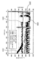
도 26에 엔진 회전수 Re, 엔진 오일 압력 Pe, 냉각수 압력 Pc의 시계열 변화를 나타낸다. 엔진 회전수 Re(도면에서는 그래프 2201)의 변화에 맞추어, 엔진 오일 압력 Pe(도면에서는 그래프 2202)와 냉각수 압력 Pc(도면에서는 그래프 2203)가 변화된다. 이것은, 도 25에 도시한 바와 같이, 오일 펌프(2102)와 워터 펌프(2105)가 엔진(1901)의 회전부에 장착되어 있고, 엔진(1901)의 회전에 맞추어 구동하는 것을 나타내고 있다.26 shows time series changes of the engine speed Re, the engine oil pressure Pe, and the coolant pressure Pc. The engine oil pressure Pe (
여기서, 워터 펌프(2105)가 무언가의 요인에 의해 고장난 경우를 생각한다. 워터 펌프(2105)가 고장남으로써, 냉각수가 순환하지 않거나, 혹은 충분한 순환량이 얻어지지 않는다고 하는 상황이 발생한다. 이 경우, 도 26의 그래프 2204에 나타내는 바와 같이, 냉각수 압력에 통상과는 다른 변동이 발생한다. 이에 의해, 엔진 회전수 Re, 엔진 오일 압력 Pe, 냉각수 압력 Pc 사이의 상관에 변화가 발생하게 된다.Here, the case where the
본 실시예의 이상 검출 장치는, 그러한 생각에 기초하는 것이며, 상기 엔진 회전수 Re, 엔진 오일 압력 Pe, 냉각수 압력 Pc를 각각 회전수 센서(601a), 엔진 오일 압력 센서(601b), 냉각수 센서(601c)에 의해 검출하고, 그 센서값을 입력으로서, 정상 동작시의 상관 계수를 기준으로 하여, 이상 동작시의 상관 계수의 변화를 검출한다. 이에 의해 엔진 오일 계통 혹은 냉각수 냉각 계통의 이상[상기한 예에서는 워터 펌프(210)의 고장]을 검출할 수 있다.The abnormality detection apparatus of this embodiment is based on such a thought, and the engine speed Re, the engine oil pressure Pe, and the coolant pressure Pc are respectively set by the
본 실시예에 있어서도 정상 동작시의 상관 계수를 얻기 위해서는, 상술한 제6 실시예와 마찬가지로 다른 기간의 상관 계수를 사용한다.Also in this embodiment, in order to obtain the correlation coefficient in normal operation, the correlation coefficient of another period is used similarly to the sixth embodiment described above.
도 27은 본 실시예에 있어서의 이상 검출 장치(1)의 구성을 도시하는 도면이다. 본 실시예에 있어서의 이상 검출 장치(1)는, 도 24에 있어서의 온도 센서(501a, 501b, 501c, 501d)를 회전수 센서(601a), 엔진 오일 압력 센서(601b), 냉각수 압력 센서(601c)로 치환한 것이다.FIG. 27 is a diagram showing the configuration of the
회전수 센서(601a), 엔진 오일 압력 센서(601b), 냉각수 압력 센서(601c)는, 각각 상기 엔진 회전수 Re, 엔진 오일 압력 Pe, 냉각수 압력 Pc를 검출한다.The
상관 계수 산출부(502)는, 회전수 센서(601a), 엔진 오일 압력 센서(601b), 냉각수 압력 센서(601)로부터 출력되는 센서 신호를 3개 이상의 다른 소정 기간의 각각에 있어서 입력하고, 센서마다 동일 기간에 있어서의 3개 이상의 시계열적 물리 상태 정보를 생성한다. 그리고 그 센서마다의 3개 이상의 시계열적 물리 상태 정보로부터 상관 계수를 3개 이상 산출한다.The correlation
상관 계수 비교부(103) 및 이상 판정부(104)는, 제1 실시예 등과 동일한 처리를 행하여, 상관 비교 합계값의 백분율이 50% 이상에 대해서는, 「경고 판정」, 80% 이상에 대해서는, 「이상 판정」을 출력한다.The correlation
제8 실시예Eighth embodiment
[엔진 오일 냉각 계통 및 냉각수 냉각 계통의 사례 (2)에 대해][About Case (2) of Engine Oil Cooling System and Cooling Water Cooling System]
본 발명의 또 다른 실시예를 상술한 실시예 및 도 28 및 도 29를 사용하여 설명한다.Another embodiment of the present invention will be described using the above-described embodiment and FIGS. 28 and 29.
본 실시예도, 복수의 센서가 복수의 관련되는 물리 상태로서 2개 이상의 관련되어 변화되는 물리 상태를 검출하는 경우의 것이다. 또한, 본 실시예는, 검출되는 물리 상태가 2개인 경우의 것이다.This embodiment is also a case where a plurality of sensors detects two or more associated and changed physical states as a plurality of related physical states. In addition, this embodiment is a case where two physical states are detected.
도 28은 도 25에 나타낸 엔진 오일 냉각 계통 및 냉각수 냉각 계통에 있어서의 라디에이터 입구 냉각수 온도 Tr(도면에서는 그래프 2301)과 엔진 오일 온도 Te(도면에서는 그래프 2302)의 시계열 변화를 나타내는 도면이다. 도 28에 나타내는 바와 같이, 라디에이터 입구 냉각수 온도 Tr(도면에서는 그래프 2301)과 엔진 오일 온도 Te(도면에서는 그래프 2302)를 보면, 정상시에는 엔진 오일 온도 Te의 상승에 맞추어 라디에이터 입구 냉각수 온도 Tr도 상승하지만, 무언가의 고장에 의해 엔진 오일 온도 Te가 급격하게 상승한다고 하는 상황이 발생한 경우, 이들 2개의 온도의 상관 계수의 변화로부터, 어느 쪽인가의 온도에 이상이 발생하였다고 하는 것만큼은 판정할 수 있다. 3개의 센서 데이터(3개의 물리 상태)의 관계를 이용하면, 어느 센서 데이터에 통상과는 다른 경향이 발생하였는지를 검지할 수 있지만, 2개의 센서 데이터(2개의 물리 상태) 뿐인 경우에는, 그들 2개의 센서에 관계되는 부위에 이상이 발생하였다고 하는 것만을 판정할 수 있다.It is a figure which shows time-series change of the radiator inlet cooling water temperature Tr (
본 실시예의 이상 검출 장치는, 그러한 생각에 기초하는 것이며, 상기 엔진 오일 온도 Te 및 라디에이터 입구 냉각수 온도 Tr을 각각 엔진 오일 온도 센서(601a) 및 라디에이터 입구 냉각수 온도 센서(601b)에 의해 검출하고, 그 센서값을 입력으로서, 정상 동작시의 상관 계수를 기준으로 하여, 이상 동작시의 상관 계수의 변화를 검출한다. 이에 의해 엔진 오일 계통과 냉각수 냉각 계통 중 어느 하나가 이상인 것을 검출할 수 있다.The abnormality detection apparatus of this embodiment is based on such a thought, and the engine oil temperature Te and the radiator inlet coolant temperature Tr are detected by the engine
본 실시예에 있어서도 정상 동작시의 상관 계수를 얻기 위해서는, 상술한 제6 실시예와 마찬가지로 다른 기간의 상관 계수를 사용한다.Also in this embodiment, in order to obtain the correlation coefficient in normal operation, the correlation coefficient of another period is used similarly to the sixth embodiment described above.
도 29는 본 실시예에 있어서의 이상 검출 장치(1)의 구성을 도시하는 도면이다. 본 실시예에 있어서의 이상 검출 장치(1)는, 도 24에 있어서의 온도 센서(501a, 501b, 501c, 501d)를 엔진 오일 온도 센서(701a) 및 라디에이터 입구 냉각수 온도 센서(701b)로 치환한 것이다.FIG. 29 is a diagram showing the configuration of the
엔진 오일 온도 센서(701a) 및 라디에이터 입구 냉각수 온도 센서(701b)는, 각각 상기 엔진 오일 온도 Te 및 라디에이터 입구 냉각수 온도 Tr을 검출한다.The engine
상관 계수 산출부(502)는, 엔진 오일 온도 센서(701a) 및 라디에이터 입구 냉각수 온도 센서(701b)로부터 출력되는 센서 신호를 3개의 다른 소정 기간의 각각에 있어서 입력하고, 센서마다 동일 기간에 있어서의 3개의 시계열적 물리 상태 정보를 생성한다. 그리고 그 센서마다의 3개의 시계열적 물리 상태 정보로부터 상관 계수를 6개 산출한다.The correlation
상관 계수 비교부(103) 및 이상 판정부(104)는, 제1 실시예 등과 마찬가지의 처리를 행하여, 상관 비교 합계값의 백분율이 50% 이상에 대해서는, 「경고 판정」, 80% 이상에 대해서는, 「이상 판정」을 출력한다.The correlation
건설 기계 전반에 본 발명을 널리 적용하는 것이 가능하다.It is possible to apply the present invention to construction machinery in general.
1 : 이상 검출 장치
101(101a, 101b, 101c) : 센서
102 : 상관 계수 산출부
103 : 상관 계수 비교부
104 : 이상 판정부
201(201a, 201b, 201c) : 펌프 케이스 드레인 압력 센서
202 : 조작 정보 검출부
203 : 펌프 동작 판정부
301(301a, 301b, 301c) : 엔진 기통 온도 센서
302 : 회전수 센서
402 : 상대비 산출부
403 : 상대비 비교부
501a : 외기 온도 센서
501b : 작동유 온도 센서
501c : 작동유 쿨러 입구 온도 센서
501d : 작동유 쿨러 출구 온도 센서
502 : 상관 계수 산출 수단
601a : 회전수 센서
601b : 엔진 오일 압력 센서
601c : 냉각수 압력 센서
701a : 엔진 오일 온도 센서
701b : 냉각수 온도 센서
871, 872, 873 : 유압 실린더
902 : 엔진
904 : 유압 펌프
906 : 컨트롤 밸브
1901 : 엔진
1902 : 컨트롤 밸브
1903 : 유압 실린더
1904 : 작동유 쿨러
1905 : 릴리프 밸브
1906 : 작동유 탱크
1907 : 유압 펌프
1908 : 냉각 팬
2101 : 라디에이터
2102 : 오일 펌프
2103 : 오일 쿨러
2104 : 워터 재킷
2105 : 워터 펌프
2106 : 오일 팬1: abnormal detection device
101 (101a, 101b, 101c): sensor
102: correlation coefficient calculation unit
103: correlation coefficient comparison unit
104: abnormality determination unit
201 (201a, 201b, 201c): pump case drain pressure sensor
202: operation information detection unit
203: pump operation determination unit
301 (301a, 301b, 301c): engine cylinder temperature sensor
302: speed sensor
402: relative ratio calculation unit
403: relative ratio comparison unit
501a: outside temperature sensor
501b: Hydraulic oil temperature sensor
501c: Hydraulic oil cooler inlet temperature sensor
501d: Oil Cooler Outlet Temperature Sensor
502: correlation coefficient calculation means
601a: rotation speed sensor
601b: Engine Oil Pressure Sensor
601c: Coolant Pressure Sensor
701a: Engine Oil Temperature Sensor
701b: Coolant Temperature Sensor
871, 872, 873: Hydraulic Cylinder
902: engine
904: Hydraulic Pump
906: Control Valve
1901: engine
1902: control valve
1903: Hydraulic Cylinder
1904: Working oil cooler
1905: relief valve
1906: working oil tank
1907: Hydraulic Pump
1908: cooling fan
2101: radiator
2102: Oil Pump
2103: Oil Cooler
2104: water jacket
2105: Water Pump
2106: Oil Pan
Claims (13)
상기 복수의 센서 수단으로부터 출력되는 복수의 센서 정보를 입력하여 상기 복수의 센서 수단에 대응하는 복수의 센서 정보의 각각의 소정 기간에 있어서의 시계열적 물리 상태 정보를 생성하고, 상기 복수의 센서 정보의 각각의 시계열적 물리 상태 정보에 대해, 시계열적 물리 상태 정보간의 복수의 상관 계수를 산출하는 상관 계수 산출 수단과,
상기 상관 계수 산출 수단에 의해 산출된 복수의 상관 계수끼리를 비교하여 상기 복수의 상관 계수의 각각에 대한 다른 상관 계수와의 차이의 정도를 산출하는 상관 계수 비교 수단과,
상기 상관 계수 비교 수단에 의해 산출된 차이의 정도가 미리 정해진 값을 초과하고 있는 경우에, 대응하는 센서 수단에 관련되는 부위에 이상이 있었다고 판정하는 이상 판정 수단을 구비한 것을 특징으로 하는, 이상 검출 장치.In the abnormality detection device of a construction machine provided with a plurality of sensor means, respectively disposed on a plurality of sites of the construction machine, detects a plurality of related physical states and outputs a plurality of sensor information,
Inputs a plurality of sensor information output from the plurality of sensor means to generate time-series physical state information in each predetermined period of the plurality of sensor information corresponding to the plurality of sensor means, Correlation coefficient calculating means for calculating a plurality of correlation coefficients between time-series physical state information, for each time-series physical state information;
Correlation coefficient comparing means for comparing a plurality of correlation coefficients calculated by the correlation coefficient calculating means and calculating a degree of difference with other correlation coefficients for each of the plurality of correlation coefficients;
In the case where the degree of the difference calculated by the correlation coefficient comparing means exceeds a predetermined value, abnormality detection means for determining that there is an abnormality in a portion related to the corresponding sensor means is provided. Device.
상기 상관 계수 산출 수단은, 상기 3개 이상의 센서 수단으로부터 출력되는 3개 이상의 센서 정보를 입력하여, 동일 기간에 있어서의 3개 이상의 시계열적 물리 상태 정보를 생성하고, 상기 3개 이상의 시계열적 물리 상태 정보로부터 상기 복수의 상관 계수를 산출하는 것을 특징으로 하는, 이상 검출 장치.The method according to claim 1, wherein the plurality of sensor means are three or more sensor means for detecting three or more identical physical states as the plurality of related physical states,
The correlation coefficient calculating means inputs three or more sensor information outputted from the three or more sensor means to generate three or more time-series physical state information in the same period, and the three or more time-series physical state The abnormality detection device, characterized in that the plurality of correlation coefficients are calculated from the information.
상기 상관 계수 산출 수단은, 상기 2개 이상의 센서 수단으로부터 출력되는 2개 이상의 센서 정보를 3개 이상의 다른 기간의 각각에 있어서 입력하여, 센서 수단마다 동일 기간에 있어서의 3개 이상의 시계열적 물리 상태 정보를 생성하고, 상기 센서 수단마다의 3개 이상의 시계열적 물리 상태 정보로부터 상기 복수의 상관 계수를 산출하는 것을 특징으로 하는, 이상 검출 장치.The method according to claim 1, wherein the plurality of sensor means are two or more sensor means for detecting two or more related and changed physical states as the plurality of related physical states,
The correlation coefficient calculating means inputs two or more sensor information output from the two or more sensor means in each of three or more different periods, so that three or more time-series physical state information in the same period for each sensor means. And generating the plurality of correlation coefficients from three or more time-series physical state information for each of the sensor means.
상기 복수의 센서 수단은, 상기 복수의 유압 펌프에 각각 배치되어 상기 복수의 유압 펌프의 압력을 검출하고, 압력 정보를 출력하는 복수의 압력 센서를 포함하고,
상기 이상 판정 수단은, 상기 상관 계수 비교 수단에 의해 산출된 차이의 정도가 미리 정해진 값을 초과하고 있는 경우에, 대응하는 상관 계수의 압력 센서에 관련되는 유압 펌프에 이상이 있었다고 판정하는 것을 특징으로 하는, 이상 검출 장치.The construction machine according to claim 1 or 2, wherein the construction machine comprises a plurality of hydraulic pumps,
The plurality of sensor means each includes a plurality of pressure sensors disposed in the plurality of hydraulic pumps to detect pressures of the plurality of hydraulic pumps and output pressure information,
The abnormality determining means determines that there is an abnormality in the hydraulic pump related to the pressure sensor of the corresponding correlation coefficient when the degree of difference calculated by the correlation coefficient comparing means exceeds a predetermined value. Abnormal detection device.
상기 조작 정보에 기초하여 각 유압 펌프의 동작 상태를 판정하는 유압 펌프 동작 판정 수단을 구비하고,
상기 상관 계수 산출 수단은, 상기 동작 판정 수단의 판정 결과에 기초하여, 동작하고 있는 유압 펌프만의 압력 정보를 사용하여 상기 상관 계수를 산출하는 것을 특징으로 하는, 이상 검출 장치.7. The apparatus according to claim 6, further comprising: operation information detecting means for detecting operation information of the construction machine;
Hydraulic pump operation determination means for determining the operation state of each hydraulic pump based on the operation information,
The correlation coefficient calculating means calculates the correlation coefficient using pressure information of only the hydraulic pump that is operating based on the determination result of the operation determining means.
상기 복수의 센서 수단은, 상기 엔진의 복수의 기통에 각각 배치되어 상기 복수의 기통의 온도를 검출하고, 온도 정보를 출력하는 복수의 온도 센서를 포함하고,
상기 이상 판정 수단은, 상기 상관 계수 비교 수단에 의해 산출된 차이의 정도가 미리 정해진 값을 초과하고 있는 경우에, 대응하는 온도 센서에 관련되는 기통에 이상이 있었다고 판정하는 것을 특징으로 하는, 이상 검출 장치.The construction machine according to claim 1 or 2, wherein the construction machine includes an engine in which a plurality of cylinders are arranged,
The plurality of sensor means includes a plurality of temperature sensors, each disposed in a plurality of cylinders of the engine to detect the temperature of the plurality of cylinders, and outputs temperature information,
The abnormality determining means determines that there is an abnormality in the cylinder associated with the corresponding temperature sensor when the degree of the difference calculated by the correlation coefficient comparing means exceeds a predetermined value. Device.
상기 상관 계수 산출 수단은, 상기 회전수 검출 수단에 의해 검출된 상기 엔진 회전수가 소정의 값 이상인 경우만의 상기 온도 정보를 사용하여 상기 상관 계수를 산출하는 것을 특징으로 하는, 이상 검출 장치.9. A rotation speed detecting means for detecting an engine speed of the engine according to claim 8,
And the correlation coefficient calculating means calculates the correlation coefficient using the temperature information only when the engine speed detected by the rotation speed detecting means is equal to or greater than a predetermined value.
엔진과,
상기 엔진에 의해 구동되고, 탱크 내의 작동유를 퍼올려 토출하는 유압 펌프와,
상기 유압 펌프로부터 토출된 작동유가 컨트롤 밸브를 통해 공급되고, 그 작동유에 의해 구동되는 유압 액추에이터와,
상기 유압 액추에이터로부터 상기 컨트롤 밸브를 통해 탱크로 복귀되는 작동유를 냉각하는 작동유 냉각 장치를 구비하고,
상기 작동유 냉각 장치는,
작동유가 복귀되는 경로에 배치되고, 상기 작동유를 냉각하는 작동유 쿨러와,
상기 작동유 쿨러를 냉각하는 냉각 팬을 갖고,
상기 복수의 센서 수단은,
외기 온도를 검출하는 제1 온도 센서와,
상기 탱크 내의 작동유의 온도를 검출하는 제2 온도 센서와,
상기 작동유 쿨러의 입구측에 있어서의 작동유의 온도를 검출하는 제3 온도 센서와,
상기 작동유 쿨러의 출구측에 있어서의 작동유의 온도를 검출하는 제4 온도 센서를 포함하고,
상기 이상 판정 수단은, 상기 상관 계수 비교 수단에 의해 산출된 차이의 정도가 미리 정해진 값을 초과하고 있는 경우에, 대응하는 온도 센서에 관련되는 상기 작동 냉각 장치의 부위에 이상이 있었다고 판정하는 것을 특징으로 하는, 이상 검출 장치.According to claim 1 or 3, wherein the construction machine,
Engine,
A hydraulic pump driven by the engine to pump up and discharge hydraulic oil in the tank;
A hydraulic actuator supplied with hydraulic oil discharged from the hydraulic pump through a control valve, and driven by the hydraulic oil;
A hydraulic oil cooling device for cooling hydraulic oil returned from the hydraulic actuator to the tank through the control valve,
The hydraulic fluid cooling device,
A hydraulic oil cooler disposed in a path through which hydraulic oil is returned, and cooling the hydraulic oil;
Has a cooling fan for cooling the hydraulic oil cooler,
The plurality of sensor means,
A first temperature sensor for detecting outside temperature,
A second temperature sensor for detecting a temperature of hydraulic oil in the tank;
A third temperature sensor which detects a temperature of the hydraulic oil at the inlet side of the hydraulic oil cooler,
And a fourth temperature sensor for detecting the temperature of the hydraulic oil at the outlet side of the hydraulic oil cooler,
The abnormality judging means judges that there is an abnormality in a portion of the working cooling device associated with the corresponding temperature sensor when the degree of difference calculated by the correlation coefficient comparing means exceeds a predetermined value. An abnormality detection apparatus.
엔진과,
상기 엔진에 의해 구동되고, 오일 팬 내의 엔진 오일을 퍼올려 토출하여 엔진 내를 순환시키는 오일 펌프, 상기 엔진 내를 순환한 엔진 오일이 상기 오일 팬으로 복귀되는 경로에 배치되고, 상기 작동유를 냉각하는 오일 쿨러를 갖는 엔진 오일 냉각 계통과,
상기 오일 쿨러를 냉각하는 워터 재킷, 상기 엔진에 의해 구동되고, 냉각수를 상기 워터 재킷에 공급하는 워터 펌프, 상기 워터 재킷을 통과한 냉각수가 상기 워터 펌프로 복귀되는 경로에 배치되고, 상기 냉각수를 냉각하는 라디에이터, 상기 엔진에 의해 구동되고, 상기 라디에이터를 냉각하는 냉각 팬을 갖는 냉각수 냉각 계통을 구비하고,
상기 복수의 센서 수단은,
상기 엔진의 엔진 회전수를 검출하는 회전수 센서와,
상기 오일 펌프로부터 토출된 엔진 오일의 압력을 검출하는 제1 압력 센서와,
상기 워터 펌프로부터 토출된 냉각수의 압력을 검출하는 제2 압력 센서를 포함하고,
상기 상관 함수 산출 수단은, 상기 회전수 센서로부터 출력되는 엔진 회전수 정보와 상기 제1 및 제2 압력 센서로부터 출력되는 압력 정보의 각각에 대해 다른 정보와의 상관 계수를 산출하고,
상기 상관 계수 비교 수단은, 상기 상관 계수 산출 수단에 의해 산출된 상관 계수끼리를 비교하여 차이의 정도를 산출하고,
상기 이상 판정 수단은, 상기 상관 계수 비교 수단에 의해 산출된 차이의 정도가 미리 정해진 값을 초과하고 있는 경우에, 대응하는 센서 수단에 관련되는 기기에 이상이 있었다고 판정하는 것을 특징으로 하는, 이상 검출 장치.According to claim 1 or 3, wherein the construction machine,
Engine,
An oil pump driven by the engine and configured to circulate the engine oil by pumping up and discharging the engine oil in the oil pan, the engine oil circulating in the engine being returned to the oil pan, and cooling the working oil. Engine oil cooling system with oil cooler,
A water jacket for cooling the oil cooler, a water pump driven by the engine, for supplying cooling water to the water jacket, a cooling water passing through the water jacket is disposed in a path to return to the water pump, and cooling the cooling water And a cooling water cooling system having a radiator which is driven by the engine and a cooling fan that cools the radiator,
The plurality of sensor means,
A rotation speed sensor for detecting an engine speed of the engine;
A first pressure sensor detecting a pressure of the engine oil discharged from the oil pump;
A second pressure sensor detecting a pressure of the cooling water discharged from the water pump,
The correlation function calculating means calculates a correlation coefficient between the engine speed information output from the rotation speed sensor and the other information for each of the pressure information output from the first and second pressure sensors,
The correlation coefficient comparison means compares the correlation coefficients calculated by the correlation coefficient calculation means to calculate the degree of difference,
The abnormality judging means judges that there is an abnormality in a device related to the corresponding sensor means when the degree of the difference calculated by the correlation coefficient comparing means exceeds a predetermined value. Device.
엔진과,
상기 엔진에 의해 구동되고, 오일 팬 내의 엔진 오일을 퍼올려 토출하여 엔진 내를 순환시키는 오일 펌프, 상기 엔진 내를 순환한 엔진 오일이 상기 오일 팬으로 복귀되는 경로에 배치되고, 상기 작동유를 냉각하는 오일 쿨러를 갖는 엔진 오일 냉각 계통과,
상기 오일 쿨러를 냉각하는 워터 재킷, 상기 엔진에 의해 구동되고, 냉각수를 상기 워터 재킷에 공급하는 워터 펌프, 상기 워터 재킷을 통과한 냉각수가 상기 워터 펌프로 복귀되는 경로에 배치되고, 상기 냉각수를 냉각하는 라디에이터, 상기 엔진에 의해 구동되고, 상기 라디에이터를 냉각하는 냉각 팬을 갖는 냉각수 냉각 계통을 구비하고,
상기 복수의 센서 수단은,
상기 엔진 오일의 온도를 검출하는 제1 온도 센서와,
상기 냉각수의 온도를 검출하는 제2 온도 센서를 포함하고,
상기 이상 판정 수단은, 상기 상관 계수 비교 수단에 의해 산출된 차이의 정도가 미리 정해진 값을 초과하고 있는 경우에, 상기 엔진 오일 냉각 계통 및 상기 냉각수 냉각 계통 중, 대응하는 온도 센서에 관련되는 것에 이상이 있었다고 판정하는 것을 특징으로 하는, 이상 검출 장치.According to claim 1 or 3, wherein the construction machine,
Engine,
An oil pump driven by the engine and configured to circulate the engine oil by pumping up and discharging the engine oil in the oil pan, the engine oil circulating in the engine being returned to the oil pan, and cooling the working oil. Engine oil cooling system with oil cooler,
A water jacket for cooling the oil cooler, a water pump driven by the engine, for supplying cooling water to the water jacket, a cooling water passing through the water jacket is disposed in a path to return to the water pump, and cooling the cooling water And a cooling water cooling system having a radiator which is driven by the engine and a cooling fan that cools the radiator,
The plurality of sensor means,
A first temperature sensor detecting a temperature of the engine oil;
A second temperature sensor for detecting the temperature of the cooling water,
The abnormality determining means is abnormal to the one associated with the corresponding temperature sensor among the engine oil cooling system and the cooling water cooling system when the degree of the difference calculated by the correlation coefficient comparing means exceeds a predetermined value. The abnormality detection apparatus characterized by the above-mentioned.
상기 이상 판정 수단은, 상기 상대비 비교 수단에 의해 산출된 차이의 정도가 미리 정해진 값을 초과하고 있는 경우에, 대응하는 센서 수단에 관련되는 부위에 이상이 있었다고 판정하는 것을 특징으로 하는, 이상 검출 장치.
13. The method according to any one of claims 1 to 12, wherein, instead of the correlation coefficient calculating means and the correlation coefficient comparing means, a plurality of time-series physical state information for each time-series physical state information of the plurality of sensor information. Relative ratio comparison means for comparing the relative ratios calculated by the relative ratio calculation means and the relative ratios calculated by the relative ratio calculation means and calculating the degree of the difference between the other relative values for each of the plurality of relative values. With means,
The abnormality judging means judges that there is an abnormality in a portion related to the corresponding sensor means when the degree of the difference calculated by the relative ratio comparing means exceeds a predetermined value. Device.
Applications Claiming Priority (2)
| Application Number | Priority Date | Filing Date | Title |
|---|---|---|---|
| JP2009071120 | 2009-03-24 | ||
| JPJP-P-2009-071120 | 2009-03-24 |
Publications (1)
| Publication Number | Publication Date |
|---|---|
| KR20120000050A true KR20120000050A (en) | 2012-01-03 |
Family
ID=42780714
Family Applications (1)
| Application Number | Title | Priority Date | Filing Date |
|---|---|---|---|
| KR1020117018995A KR20120000050A (en) | 2009-03-24 | 2010-03-03 | Device for detecting abnormality in construction machine |
Country Status (7)
| Country | Link |
|---|---|
| US (1) | US8997472B2 (en) |
| EP (1) | EP2413124B1 (en) |
| JP (1) | JP5220917B2 (en) |
| KR (1) | KR20120000050A (en) |
| CN (1) | CN102326065B (en) |
| AU (1) | AU2010228582B2 (en) |
| WO (1) | WO2010110021A1 (en) |
Cited By (2)
| Publication number | Priority date | Publication date | Assignee | Title |
|---|---|---|---|---|
| KR101393583B1 (en) * | 2012-12-17 | 2014-05-12 | 현대자동차 주식회사 | Detecting method of malfunction of sensor |
| KR20160066990A (en) * | 2014-12-03 | 2016-06-13 | 대우조선해양 주식회사 | Apparatus for detecting rmp of marine engine |
Families Citing this family (38)
| Publication number | Priority date | Publication date | Assignee | Title |
|---|---|---|---|---|
| JP5832814B2 (en) * | 2011-08-11 | 2015-12-16 | 株式会社エヌ・ティ・ティ・データ | Abnormality detection device, abnormality detection method, abnormality detection program |
| JP5794034B2 (en) * | 2011-08-18 | 2015-10-14 | 富士ゼロックス株式会社 | Failure prediction system and program |
| US9664208B2 (en) * | 2011-12-28 | 2017-05-30 | Volvo Construction Equipment Ab | Engine control method of construction machine |
| JP5718841B2 (en) * | 2012-03-12 | 2015-05-13 | トヨタ自動車株式会社 | Control device for internal combustion engine |
| JP5836234B2 (en) * | 2012-09-20 | 2015-12-24 | 本田技研工業株式会社 | Ranma fall detection device |
| JP6304767B2 (en) * | 2012-12-14 | 2018-04-04 | 日本電気株式会社 | SENSOR MONITORING DEVICE, SENSOR MONITORING METHOD, AND SENSOR MONITORING PROGRAM |
| JP2015072512A (en) * | 2013-10-01 | 2015-04-16 | 大阪瓦斯株式会社 | Plant facility abnormality diagnostic device |
| JP6223897B2 (en) * | 2014-04-17 | 2017-11-01 | 株式会社日立製作所 | Abnormality detection device and abnormality detection system |
| US9523306B2 (en) * | 2014-05-13 | 2016-12-20 | International Engine Intellectual Property Company, Llc. | Engine cooling fan control strategy |
| JP6381282B2 (en) * | 2014-05-16 | 2018-08-29 | 三菱電機ビルテクノサービス株式会社 | Abnormality detection apparatus and program |
| JP6503541B2 (en) * | 2014-06-13 | 2019-04-24 | 中国電力株式会社 | Pump abnormality detection system, pump abnormality detection method, and pump abnormality detection program |
| SG10201405714SA (en) * | 2014-09-15 | 2016-04-28 | Yokogawa Engineering Asia Pte Ltd | Method, system and computer program for fault detection in a machine |
| US9593974B2 (en) * | 2014-09-23 | 2017-03-14 | Caterpillar Inc. | System and method of monitoring oil level in transmission system of machine |
| JP6392101B2 (en) * | 2014-12-05 | 2018-09-19 | 日立建機株式会社 | Construction machine management system |
| CN105067295A (en) * | 2015-07-20 | 2015-11-18 | 柳州好顺科技有限公司 | Engineering machine fault alarm device |
| JP6031577B2 (en) * | 2015-10-28 | 2016-11-24 | 株式会社エヌ・ティ・ティ・データ | Abnormality detection device, abnormality detection method, abnormality detection program |
| ITUB20155473A1 (en) * | 2015-11-11 | 2017-05-11 | S A T E Systems And Advanced Tech Engineering S R L | METHOD OF ANALYSIS OF TIME SEQUENCES OF MEASURES OF TWO SIGNALS CHARACTERISTICS OF A SYSTEM TO DETERMINE A POSSIBLE CAUSE-EFFECT CORRELATION WITH THE SAME TIME DELAY |
| CN105298890A (en) * | 2015-11-11 | 2016-02-03 | 沈阳黎明航空发动机(集团)有限责任公司 | Method for excluding swing standard exceeding faults of fan guider of aero-engine |
| US10385799B2 (en) | 2015-12-30 | 2019-08-20 | International Business Machines Corporation | Waveform analytics for optimizing performance of a machine |
| JP2018063225A (en) * | 2016-10-14 | 2018-04-19 | 公益財団法人鉄道総合技術研究所 | Abrupt advance point extraction processing method and abrupt advance point extraction processing system of waveform data |
| CN106525286A (en) * | 2016-12-08 | 2017-03-22 | 中国北方发动机研究所(天津) | Diagnosis method and diagnosis device of water temperature sensor faults in diesel engine |
| JP6795093B2 (en) | 2017-06-02 | 2020-12-02 | 富士通株式会社 | Judgment device, judgment method and judgment program |
| JP6635090B2 (en) * | 2017-06-05 | 2020-01-22 | マツダ株式会社 | Reduction gear state diagnosis method and state diagnosis apparatus |
| JP6752183B2 (en) | 2017-09-07 | 2020-09-09 | 日立建機株式会社 | Hydraulic work machine |
| CN107544464B (en) * | 2017-09-11 | 2020-08-11 | 天津达芸科技有限公司 | Industrial fault detection method and system |
| CN107587912B (en) * | 2017-10-31 | 2020-08-21 | 潍柴动力股份有限公司 | Method and system for diagnosing working state of oil cooler |
| CN108362957B (en) * | 2017-12-19 | 2020-09-11 | 东软集团股份有限公司 | Equipment fault diagnosis method and device, storage medium and electronic equipment |
| JP6936178B2 (en) * | 2018-03-23 | 2021-09-15 | ファナック株式会社 | Anomaly detection device |
| JPWO2019235610A1 (en) * | 2018-06-08 | 2021-07-26 | 住友重機械建機クレーン株式会社 | Construction machinery |
| JP6638788B1 (en) * | 2018-09-28 | 2020-01-29 | ダイキン工業株式会社 | Abnormality determination apparatus for transport refrigeration apparatus, transport refrigeration apparatus provided with this abnormality determination apparatus, and abnormality determination method for transport refrigeration apparatus |
| CN109507446A (en) * | 2018-11-02 | 2019-03-22 | 徐州瑞田工程机械有限公司 | A kind of rotating speed of automobile engine detection method |
| CN109594607B (en) * | 2018-12-17 | 2022-01-21 | 潍柴动力股份有限公司 | Excavator walking hydraulic pump fault detection method and excavator |
| US11352767B2 (en) * | 2020-04-20 | 2022-06-07 | Caterpillar Paving Products Inc. | Engine power management strategy |
| CN114248995A (en) * | 2020-09-22 | 2022-03-29 | 佳能医疗系统株式会社 | Biochemical analyzer and reagent storage |
| CN112834255B (en) * | 2021-01-04 | 2024-01-23 | 三一重机有限公司 | Coordination testing method and fault diagnosis method of mechanical device and engineering machinery |
| CN114235439B (en) * | 2021-12-24 | 2023-08-11 | 雷沃工程机械集团有限公司 | Whole machine thermal balance test operation method of tire type loader |
| US20230305551A1 (en) * | 2022-03-25 | 2023-09-28 | Yokogawa Electric Corporation | Method and system for automated fault detection |
| EP4293457A1 (en) * | 2022-06-15 | 2023-12-20 | Siemens Aktiengesellschaft | Monitoring method, computer program product, monitoring unit, gas analysis device and use of artificial intelligence |
Family Cites Families (29)
| Publication number | Priority date | Publication date | Assignee | Title |
|---|---|---|---|---|
| US3045221A (en) * | 1958-01-22 | 1962-07-17 | Gen Atronics Corp | Monitoring device |
| US3242321A (en) * | 1965-02-11 | 1966-03-22 | Industrial Nucleonics Corp | Automatic machine analyzer |
| JPS5977514A (en) | 1982-10-26 | 1984-05-04 | Sumitomo Metal Ind Ltd | Method for evaluating deteriorated state of equipment |
| DE3473909D1 (en) * | 1983-01-19 | 1988-10-13 | Hitachi Construction Machinery | Failure detection system for hydraulic pump |
| JPS62228920A (en) | 1986-03-31 | 1987-10-07 | Ebara Res Co Ltd | Abnormality discriminating method for sensor |
| JPH03290046A (en) | 1990-04-04 | 1991-12-19 | Mitsubishi Electric Corp | Trouble diagnosing device for engine |
| JP2569389B2 (en) * | 1991-12-12 | 1997-01-08 | 株式会社エクセディ | Predictive maintenance system for press machines |
| JPH06139479A (en) * | 1992-10-23 | 1994-05-20 | Kajima Corp | Abnormality detecting method for construction equipment |
| JP3470457B2 (en) * | 1995-05-24 | 2003-11-25 | 株式会社日立製作所 | Diagnosis and analysis method and device for control system |
| US5680409A (en) | 1995-08-11 | 1997-10-21 | Fisher-Rosemount Systems, Inc. | Method and apparatus for detecting and identifying faulty sensors in a process |
| JP2000298511A (en) | 1999-04-13 | 2000-10-24 | Toshiba Corp | Equipment diagnosing device and recording medium |
| JP4285866B2 (en) * | 1999-12-22 | 2009-06-24 | 株式会社小松製作所 | Hydraulically driven cooling fan |
| EP1164550B1 (en) * | 2000-06-16 | 2008-12-03 | Ntn Corporation | Machine component monitoring, diagnosing and selling system |
| US7065570B2 (en) * | 2000-07-11 | 2006-06-20 | Komatsu Ltd. | System, method, computer program, and recording medium for machine-management |
| JP2002217811A (en) * | 2001-01-15 | 2002-08-02 | Hitachi Ltd | Method and device for detecting state, mobile terminal device and moving state observation system |
| US7079982B2 (en) * | 2001-05-08 | 2006-07-18 | Hitachi Construction Machinery Co., Ltd. | Working machine, trouble diagnosis system of working machine, and maintenance system of working machine |
| JP4133627B2 (en) * | 2003-06-30 | 2008-08-13 | 新キャタピラー三菱株式会社 | Construction machine state determination device, construction machine diagnosis device, construction machine state determination method, and construction machine diagnosis method |
| JP4032045B2 (en) * | 2004-08-13 | 2008-01-16 | 新キャタピラー三菱株式会社 | DATA PROCESSING METHOD, DATA PROCESSING DEVICE, DIAGNOSIS METHOD, AND DIAGNOSIS DEVICE |
| JP4074615B2 (en) * | 2004-11-17 | 2008-04-09 | 日立建機株式会社 | Diagnostic information display system for construction machinery |
| JP4315248B2 (en) * | 2004-12-13 | 2009-08-19 | 日立建機株式会社 | Control device for traveling work vehicle |
| US8108242B2 (en) * | 2005-02-14 | 2012-01-31 | Komatsu Ltd. | Working machine failure information centralized managing system |
| US7953559B2 (en) * | 2005-04-28 | 2011-05-31 | Caterpillar Inc. | Systems and methods for maintaining load histories |
| JP2007241572A (en) | 2006-03-07 | 2007-09-20 | Osaka Gas Co Ltd | Facility monitoring system |
| US7478489B2 (en) * | 2006-06-01 | 2009-01-20 | Deere & Company | Control system for an electronic float feature for a loader |
| JP2008142844A (en) * | 2006-12-11 | 2008-06-26 | Okuma Corp | Method for detecting abnormality of temperature sensor of machine tool |
| JP5336042B2 (en) * | 2006-12-18 | 2013-11-06 | オークマ株式会社 | Anomaly detection method of temperature sensor in machine tool |
| JP5084295B2 (en) * | 2007-02-09 | 2012-11-28 | 日立建機株式会社 | Pump torque control device for hydraulic construction machinery |
| JP4782766B2 (en) * | 2007-12-27 | 2011-09-28 | オークマ株式会社 | Machine diagnostic method and apparatus |
| DE102009060225A1 (en) * | 2009-12-23 | 2011-06-30 | Robert Bosch GmbH, 70469 | Hydraulic arrangement |
-
2010
- 2010-03-03 EP EP10755822.3A patent/EP2413124B1/en active Active
- 2010-03-03 AU AU2010228582A patent/AU2010228582B2/en active Active
- 2010-03-03 US US13/201,875 patent/US8997472B2/en active Active
- 2010-03-03 WO PCT/JP2010/053470 patent/WO2010110021A1/en active Application Filing
- 2010-03-03 JP JP2011505945A patent/JP5220917B2/en active Active
- 2010-03-03 CN CN201080008341.3A patent/CN102326065B/en active Active
- 2010-03-03 KR KR1020117018995A patent/KR20120000050A/en active Search and Examination
Cited By (2)
| Publication number | Priority date | Publication date | Assignee | Title |
|---|---|---|---|---|
| KR101393583B1 (en) * | 2012-12-17 | 2014-05-12 | 현대자동차 주식회사 | Detecting method of malfunction of sensor |
| KR20160066990A (en) * | 2014-12-03 | 2016-06-13 | 대우조선해양 주식회사 | Apparatus for detecting rmp of marine engine |
Also Published As
| Publication number | Publication date |
|---|---|
| WO2010110021A1 (en) | 2010-09-30 |
| EP2413124A4 (en) | 2017-04-12 |
| JPWO2010110021A1 (en) | 2012-09-27 |
| CN102326065B (en) | 2014-05-07 |
| EP2413124B1 (en) | 2018-07-18 |
| EP2413124A1 (en) | 2012-02-01 |
| AU2010228582A1 (en) | 2011-09-01 |
| US8997472B2 (en) | 2015-04-07 |
| US20120041663A1 (en) | 2012-02-16 |
| CN102326065A (en) | 2012-01-18 |
| JP5220917B2 (en) | 2013-06-26 |
| AU2010228582B2 (en) | 2012-09-20 |
Similar Documents
| Publication | Publication Date | Title |
|---|---|---|
| KR20120000050A (en) | Device for detecting abnormality in construction machine | |
| KR101517917B1 (en) | Operating machine instrument diagnostic apparatus and instrument diagnostic system | |
| JP5220929B2 (en) | Work machine monitoring and diagnosis device | |
| CN103649451B (en) | For determining the system and method for the health status of wellsite facility | |
| CN108575093B (en) | Fan driving system and management system | |
| CN104981615B (en) | For the hydraulic system for the engineering machinery for being provided with protection device | |
| JP5841612B2 (en) | Construction machine operation data collection device | |
| KR20080091847A (en) | Hydraulically driven industrial machine | |
| JPH07294365A (en) | Method and apparatus for display of pump efficiency | |
| US20170138018A1 (en) | Hydraulic system having diagnostic mode of operation | |
| US11181130B2 (en) | Method and system for diagnosing abnormality of hydraulic device | |
| JP6572062B2 (en) | Diagnostic equipment | |
| JP4088149B2 (en) | Abnormality monitoring method for hydraulic system | |
| JP7009408B2 (en) | Work machine | |
| KR100249772B1 (en) | Device for diagnosing a construction machine | |
| JP4178101B2 (en) | Fault diagnosis device for hydraulic oil cooling system of construction machinery | |
| WO2023112624A1 (en) | Pump diagnostic device and construction machine | |
| JP6903567B2 (en) | Work vehicle | |
| KR20230167701A (en) | Diagnosis apparatus and method for determining the state of an accumulator | |
| KR19990028049A (en) | Construction Equipment Diagnosis Device |
Legal Events
| Date | Code | Title | Description |
|---|---|---|---|
| A201 | Request for examination |