KR20110086165A - Transporting body structure and transporting method for vertical-axis type wind power generator - Google Patents
Transporting body structure and transporting method for vertical-axis type wind power generator Download PDFInfo
- Publication number
- KR20110086165A KR20110086165A KR1020117013772A KR20117013772A KR20110086165A KR 20110086165 A KR20110086165 A KR 20110086165A KR 1020117013772 A KR1020117013772 A KR 1020117013772A KR 20117013772 A KR20117013772 A KR 20117013772A KR 20110086165 A KR20110086165 A KR 20110086165A
- Authority
- KR
- South Korea
- Prior art keywords
- vertical axis
- generator
- transport mechanism
- axis wind
- frame
- Prior art date
Links
Images


Classifications
-
- B—PERFORMING OPERATIONS; TRANSPORTING
- B65—CONVEYING; PACKING; STORING; HANDLING THIN OR FILAMENTARY MATERIAL
- B65D—CONTAINERS FOR STORAGE OR TRANSPORT OF ARTICLES OR MATERIALS, e.g. BAGS, BARRELS, BOTTLES, BOXES, CANS, CARTONS, CRATES, DRUMS, JARS, TANKS, HOPPERS, FORWARDING CONTAINERS; ACCESSORIES, CLOSURES, OR FITTINGS THEREFOR; PACKAGING ELEMENTS; PACKAGES
- B65D85/00—Containers, packaging elements or packages, specially adapted for particular articles or materials
- B65D85/68—Containers, packaging elements or packages, specially adapted for particular articles or materials for machines, engines or vehicles in assembled or dismantled form
-
- B—PERFORMING OPERATIONS; TRANSPORTING
- B65—CONVEYING; PACKING; STORING; HANDLING THIN OR FILAMENTARY MATERIAL
- B65D—CONTAINERS FOR STORAGE OR TRANSPORT OF ARTICLES OR MATERIALS, e.g. BAGS, BARRELS, BOTTLES, BOXES, CANS, CARTONS, CRATES, DRUMS, JARS, TANKS, HOPPERS, FORWARDING CONTAINERS; ACCESSORIES, CLOSURES, OR FITTINGS THEREFOR; PACKAGING ELEMENTS; PACKAGES
- B65D19/00—Pallets or like platforms, with or without side walls, for supporting loads to be lifted or lowered
- B65D19/38—Details or accessories
- B65D19/44—Elements or devices for locating articles on platforms
-
- B—PERFORMING OPERATIONS; TRANSPORTING
- B65—CONVEYING; PACKING; STORING; HANDLING THIN OR FILAMENTARY MATERIAL
- B65D—CONTAINERS FOR STORAGE OR TRANSPORT OF ARTICLES OR MATERIALS, e.g. BAGS, BARRELS, BOTTLES, BOXES, CANS, CARTONS, CRATES, DRUMS, JARS, TANKS, HOPPERS, FORWARDING CONTAINERS; ACCESSORIES, CLOSURES, OR FITTINGS THEREFOR; PACKAGING ELEMENTS; PACKAGES
- B65D85/00—Containers, packaging elements or packages, specially adapted for particular articles or materials
- B65D85/20—Containers, packaging elements or packages, specially adapted for particular articles or materials for incompressible or rigid rod-shaped or tubular articles
-
- Y—GENERAL TAGGING OF NEW TECHNOLOGICAL DEVELOPMENTS; GENERAL TAGGING OF CROSS-SECTIONAL TECHNOLOGIES SPANNING OVER SEVERAL SECTIONS OF THE IPC; TECHNICAL SUBJECTS COVERED BY FORMER USPC CROSS-REFERENCE ART COLLECTIONS [XRACs] AND DIGESTS
- Y10—TECHNICAL SUBJECTS COVERED BY FORMER USPC
- Y10T—TECHNICAL SUBJECTS COVERED BY FORMER US CLASSIFICATION
- Y10T29/00—Metal working
- Y10T29/49—Method of mechanical manufacture
- Y10T29/49229—Prime mover or fluid pump making
-
- Y—GENERAL TAGGING OF NEW TECHNOLOGICAL DEVELOPMENTS; GENERAL TAGGING OF CROSS-SECTIONAL TECHNOLOGIES SPANNING OVER SEVERAL SECTIONS OF THE IPC; TECHNICAL SUBJECTS COVERED BY FORMER USPC CROSS-REFERENCE ART COLLECTIONS [XRACs] AND DIGESTS
- Y10—TECHNICAL SUBJECTS COVERED BY FORMER USPC
- Y10T—TECHNICAL SUBJECTS COVERED BY FORMER US CLASSIFICATION
- Y10T29/00—Metal working
- Y10T29/49—Method of mechanical manufacture
- Y10T29/49826—Assembling or joining
- Y10T29/49947—Assembling or joining by applying separate fastener
- Y10T29/49963—Threaded fastener
-
- Y—GENERAL TAGGING OF NEW TECHNOLOGICAL DEVELOPMENTS; GENERAL TAGGING OF CROSS-SECTIONAL TECHNOLOGIES SPANNING OVER SEVERAL SECTIONS OF THE IPC; TECHNICAL SUBJECTS COVERED BY FORMER USPC CROSS-REFERENCE ART COLLECTIONS [XRACs] AND DIGESTS
- Y10—TECHNICAL SUBJECTS COVERED BY FORMER USPC
- Y10T—TECHNICAL SUBJECTS COVERED BY FORMER US CLASSIFICATION
- Y10T29/00—Metal working
- Y10T29/49—Method of mechanical manufacture
- Y10T29/49998—Work holding
Abstract
본 발명은 수직축 풍력 발전기에 관한 것이며, 특히 수직축 풍력 발전기 운송기구 및 운송방법에 관한 것이다. 구체적으로는 박스 또는 프레임 구조이며, 발전기 받침판과 대응되는 상기 박스 또는 프레임의 일측 평면에는 상기 발전기 받침판의 복수의 표준 관통 구멍과 고정 연결되는 연결 부품이 있다.The present invention relates to a vertical axis wind generator, and more particularly to a vertical axis wind generator transport mechanism and transportation method. Specifically, there is a box or frame structure, and there is a connection part fixedly connected to a plurality of standard through holes of the generator support plate in one plane of the box or frame corresponding to the generator support plate.
Description
본 발명은 수직 풍력 발전기에 관한 것이며, 특히는 수직축 풍력 발전기의 운송기구 및 운송방법에 관한 것이다.The present invention relates to a vertical wind generator, and more particularly, to a transport mechanism and a transportation method of a vertical axis wind generator.
도 1이 도시한 바와 같이, 종래의 수직축 풍력 발전기는 발전기(2)와 수직축(11), 상하단 플랜지(15), 지지 날개(12), 블레이드(13) 등으로 구성된 풍력 터빈 장치로 구성되어 있으며, 각 부품을 대부분 분리한 후 개별적으로 운송하고 설치 현장에 도착한 후 모든 부품을 현장에서 설치 및 시운전하도록 하고 있다. 그런데, 시공 현장의 설치 조건에 제한을 받아, 각 부품의 설치 구성 공차(tolerance)가 커서 부품의 안정성과 신뢰성에 영향을 주고, 사용 수명에도 매우 큰 영향을 주고 있다. 예를 들면 일반적으로 발전기(2), 수직축(11)을 각각 별도로 운송하는 경우에, 이 두 개 핵심 부품의 설치 조합 요구사항이 매우 정밀하므로, 설치 상황에서 매우 큰 정도에서 부품의 안정성과 신뢰성에 영향을 주며, 사용 수명에도 매우 큰 영향을 주고 있다. 따라서 풍력 발전기가 일반적으로 무겁고, 운송 과정에 부품이 쉽게 파손되며, 장치 자체 사이즈가 크므로 설치가 매우 불편하며, 노동 강도가 높다.As shown in Figure 1, the conventional vertical axis wind generator is composed of a wind turbine device consisting of a generator (2) and a vertical shaft (11), upper and lower flanges (15), support blades (12), blades (13), and the like. In addition, most parts are separated and transported individually, and after installation, all parts are installed and commissioned on site. By the way, the installation condition of the construction site is limited, the installation configuration tolerance of each component is large, which affects the stability and reliability of the component, and also has a great influence on the service life. In general, for example, when the
본 발명의 목적은 상술한 종래 기술의 문제점을 해결하고, 현장 설치가 용이하고, 현장 작업량이 감소하며, 운송도 편리하며, 비용도 절감하는 수직축 풍력 발전기의 운송기구 및 운송방법을 제공하여 수직축 풍력 발전기의 광범위한 응용에 해결책을 제공하는 것이다.An object of the present invention is to solve the problems of the prior art described above, to provide a transport mechanism and transportation method of a vertical axis wind power generator that is easy to install on-site, reduced on-site work, convenient transportation, and also saves cost vertical axis wind power To provide a solution for a wide range of applications.
본 발명의 구체적인 기술적 해결책은 다음과 같다. Specific technical solutions of the present invention are as follows.
수직축 풍력 발전기의 운송기구이며, 박스 또는 프레임 구조이며, 상기 박스 또는 프레임의 일측 평면에 발전기 받침판과 대응되는 발전기 받침판(21)과 고정 연결되는 복수의 연결부품(22)을 구비한다.A transport mechanism of a vertical axis wind power generator, having a box or frame structure, and having a plurality of
상기 박스 또는 프레임의 연결 부품은 발전기 받침판에 설치된 구멍(23)을 통해 연결될 수 있다.The connecting part of the box or frame may be connected through a
상기 연결 방식은 볼트로 고정 연결할 수 있다. The connection method may be fixed by bolts.
본 발명의 수직축 풍력 발전기의 운송방법은 박스 또는 프레임의 하단면 수평 사이즈는 상단면 사이즈보다 약간 작거나 크며, 상,하단의 해당 중첩 위치에 소정의 관통 구멍을 설치하여 볼트로 상,하 박스 또는 프레임을 고정하도록 할 수 있다.In the transportation method of the vertical axis wind generator of the present invention, the horizontal size of the bottom surface of the box or the frame is slightly smaller or larger than the size of the upper surface, and the upper and lower boxes or bolts are installed by installing a predetermined through hole at the corresponding overlapping position of the upper and lower ends. It can be fixed to the frame.
상기 운송기구 내에 발전기를 수평으로 놓고, 발전기 받침판을 대응되는 운송기구의 해당 측면 평면에 고정 연결한다.The generator is placed horizontally in the vehicle and the generator support plate is fixedly connected to the corresponding side plane of the corresponding vehicle.
운송기구 내에서 지지물로 수직축(11)을 지지하며, 상기 지지물은 철강 구조물로 형성할 수 있으며, 예를 들면 철강 벨트를 프레임 또는 박스 구조의 사각형 테두리에 용접하거나, 또는 밧줄로 프레임 또는 박스 구조의 사각형 테두리에 고정할 수도 있다. Supports the
상기 운송기구의 하단면 수평 사이즈가 상단면 사이즈보다 약간 작거나 크며, 상,하단의 해당 중첩 위치에 복수의 관통 구멍을 설치하여 볼트로 상,하 운송기구을 고정하며, 다수의 운송기구를 중복 배치하여 운송할 수 있다.The horizontal size of the lower surface of the transport mechanism is slightly smaller or larger than the size of the upper surface, and installs a plurality of through holes in the corresponding overlapping positions of the upper and lower ends to fix the upper and lower transport mechanisms with bolts, and the plurality of transport apparatuses are overlapped. Can be transported.
현장에서 플랜지를 설치하는 것을 생략하여, 현장 설치 작업량을 감소하기 위해 상, 하 플랜지(15)를 수직축(11)에 설치한 후 운송할 수 있다.By omitting the installation of the flange in the field, in order to reduce the amount of work in the field can be transported after installing the upper and
본 발명의 운송기구 구조를 적용한 후, 현장 설치 작업량과 설치 시간이 종래의 분리 운송, 현장 설치를 적용하던 때의 작업량과 작업 시간에 비교하여 절반 이상이 감소시킬 수 있다. 또한 안정성 및 신뢰성이 크게 향상시킬 수 있으며, 풍력 터빈이 강한 바람을 맞았을 때 흔들리거나 공진되는 현상을 감소할 수 있다. 또한 현장 설치 시, 팬 표면 코팅에 대한 손상을 감소하여, 팬의 수명을 연장시킬 수 있다.After applying the vehicle structure of the present invention, the field installation work and installation time can be reduced by more than half compared to the work load and work time when applying the conventional separate transportation, site installation. In addition, stability and reliability can be greatly improved, and the wind turbine can be shaken or resonated when subjected to strong winds. In addition, in field installation, damage to the fan surface coating can be reduced, extending the life of the fan.
도 1은 종래기술에 따른 수직축 풍력 발전기의 구조를 나타내는 도면이다.
도 2는 본 발명의 일실시예에 따른 운송기구 구조를 나타내는 도면이다.
도 3은 본 발명의 일실시예에 따른 수직축 풍력 발전기의 수직축 고정을 나타내는 도면이다.
도 4는 본 발명의 일실시예에 따른 운송기구 중첩 구조를 나타내는 도면이다.
도 5는 본 발명의 다른 실시예에 따른 수직축 풍력 발전기의 수직축 고정을 나타내는 도면이다.1 is a view showing the structure of a vertical axis wind power generator according to the prior art.
2 is a view showing the structure of the transport mechanism according to an embodiment of the present invention.
3 is a view showing the vertical axis of the vertical axis wind power generator according to an embodiment of the present invention.
Figure 4 is a view showing a superimposition structure of the transport mechanism according to an embodiment of the present invention.
5 is a view showing the vertical axis of the vertical axis wind generator according to another embodiment of the present invention.
실시예1Example 1
도 2는 본 발명의 운송기구의 전체적인 구조를 나타내는 도면이다. 이 운송기구의 구조는 프레임 구조이다. 발전기를 수평으로 상기 프레임(4) 내에 놓으며, 상기 프레임(4)은 사각형 모양의 철강 프레임을 사용할 있다. 상기 프레임의 일측 평면에는 발전기 받침판(21)의 표준 관통 구멍과 고정 연결되는 연결 부품(22)이 설치되어 있다. 발전기 받침판에 이미 구비된 표준 구멍(23)을 이용하여 이 철강 프레임 평면에 대응되게 고정 연결 설치하며, 볼트로 고정할 수 있다. 또는 발전기 받침판 및 프레임 평면의 대응된 위치에 관통 구멍(23)을 설치하여, 볼트 등 방식으로 단단히 조이도록 할 수 있다.2 is a view showing the overall structure of the transport mechanism of the present invention. The structure of this transport mechanism is a frame structure. The generator is placed horizontally in the
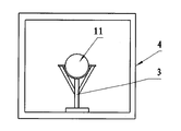
도 3은 본 발명의 수직축 풍력 발전기의 수직축 고정을 나타내는 도면이다. 철강 프레임 내 수직축(11)의 상단이 지지물(3)로 지지되며, 이 지지물은 철강 구조물일 수 있다. 철강 벨트를 프레임의 사각형 테두리에 용접하거나, 또는 밧줄을 프레임의 사각형 테두리에 고정할 수도 있다. 지지 위치는 수직축 상단에서 1/3되는 곳에 둘 수 있다. 3 is a view showing the vertical axis of the vertical axis wind generator of the present invention. The upper end of the
현장에서 플랜지를 설치하는 것을 생략하여, 현장 설치 작업량을 감소하기 위해 상하 플랜지(15)를 수직축(11)에 설치한 후 운송하며, 이를 통해 현장 설치로 플랜지와 축 사이의 공차의 설치 요구사항이 낮은 결점을 제거하고, 팬의 안정성을 향상시키고, 현장 설치 시간을 감소할 수 있다. By omitting the installation of the flange in the field, the upper and
도 4를 참조하면, 운송에 편리하기 위해 이 프레임의 하단면 수평 사이즈가 상단면 사이즈보다 약간 작거나 크며, 동시에 상,하단의 해당 중첩 위치에 복수의 관통 구멍(5)을 설치하여 볼트(6)로 상,하 프레임을 고정하도록 하며, 이를 통해 여러 개의 프레임의 중첩 설치가 가능하며, 운송 비용을 절감할 수 있다. 4, the horizontal size of the lower surface of the frame is slightly smaller or larger than the size of the upper surface for convenience of transportation, and at the same time, a plurality of through
실시예2Example 2 ::
도 2는 본 발명의 운송기구의 전체적인 구조를 나타내는 도면이다. 이 운송기구의 구조는 프레임 구조이다. 발전기를 수평으로 상기 프레임(4) 내에 놓으며, 상기 프레임(4)은 사각형 모양의 철강 박스를 사용할 있다. 상기 프레임의 일측 평면에는 발전기 받침판(21)의 표준 관통 구멍과 고정 연결되는 연결 부품(22)이 설치되어 있다. 발전기 받침판에 이미 구비된 표준 구멍(23)을 이용하여 이 철강 프레임 일측 평면에 대응되게 고정 연결 설치하며, 볼트로 고정할 수 있다. 또는 발전기 받침판 및 프레임 평면의 대응된 위치에 관통 구멍(23)을 설치하여, 볼트 등 방식으로 단단히 조이도록 할 수 있다.2 is a view showing the overall structure of the transport mechanism of the present invention. The structure of this transport mechanism is a frame structure. The generator is placed horizontally in the
도 3은 본 발명의 수직축 풍력 발전기의 수직축 고정을 나타내는 도면이다. 철강 박스 내 수직축(11)의 상단이 지지물(3)로 지지된다. 3 is a view showing the vertical axis of the vertical axis wind generator of the present invention. The upper end of the
현장에서 플랜지를 설치하는 것을 생략하여, 현장 설치 작업량을 감소하기 위해 상하 플랜지(15)를 수직축(11)에 설치한 후 운송하며, 이를 통해 현장 설치로 플랜지와 축 사이의 공차의 설치 요구사항이 낮은 결점을 제거하고, 팬의 안정성을 향상시키고, 현장 설치 시간을 감소할 수 있다. By omitting the installation of the flange in the field, the upper and
도 4를 참조하면, 운송에 편리하기 위해 상기 박스의 하단면 수평 사이즈가 상단면 사이즈보다 약간 작거나 크며, 동시에 상,하단의 해당 중첩 위치에 복수의 관통 구멍(5)을 설치하여 볼트(6)로 상,하 박스를 고정하도록 하며, 이를 통해 여러 개의 박스의 중첩 설치가 가능하며, 운송 비용을 절감할 수 있다. Referring to FIG. 4, the horizontal size of the bottom surface of the box is slightly smaller or larger than the size of the top surface for convenience of transportation, and at the same time, a plurality of through
도 5는 본 발명의 다른 실시예에 따른 수직축 풍력 발전기의 수직축 고정을 나타내는 도면이다. 철강 박스(4) 내 수직축(11)이 V자형 지지물(3)로 지지된다. 5 is a view showing the vertical axis of the vertical axis wind generator according to another embodiment of the present invention. The
1: 풍력 터빈 11:수직축
12: 지지 날개 13: 블레이드
15: 상하 플랜지 2: 발전기
21: 발전기 하단 22: 연결 부품
23: 관통 구멍, 표준 구멍 3: 지지물
4: 박스 또는 프레임 5:관통 구멍
6: 볼트1: wind turbine 11: vertical shaft
12: support wing 13: blade
15: upper and lower flange 2: generator
21: bottom of generator 22: connecting parts
23: through hole, standard hole 3: support
4: box or frame 5: through hole
6: bolt
Claims (8)
상기 박스 또는 프레임의 연결 부품(22)은 발전기 받침판에 설치된 구멍(23)을 통해 연결되는 것을 특징으로 하는 수직축 풍력 발전기의 운송기구.The method according to claim 1,
The connecting part (22) of the box or frame is a transport mechanism of the vertical axis wind generator, characterized in that connected through the hole (23) installed in the generator support plate.
상기 구멍(23)은 발전기 받침판에 형성되어 있는 표준 구멍인 것을 특징으로 하는 수직축 풍력 발전기의 운송기구.The method according to claim 2,
The hole 23 is a transport mechanism of a vertical axis wind generator, characterized in that the standard hole formed in the generator support plate.
상기 연결 방식은 볼트로 고정 연결된 것을 특징으로 하는 수직축 풍력 발전기의 운송기구.The method according to claim 2 or 3,
The connecting method is a transport mechanism of a vertical axis wind generator, characterized in that the fixed connection with the bolt.
상기 박스 또는 프레임의 하단면 수평 사이즈가 상단면 사이즈보다 약간 작거나 크며, 상,하단의 해당 중첩 위치에 복수의 관통 구멍(5)을 설치하여 볼트(6)로 상,하 박스 또는 프레임을 고정하도록 하는 것을 특징으로 하는 수직축 풍력 발전기의 운송기구.The method according to claim 1,
The horizontal size of the lower surface of the box or frame is slightly smaller or larger than the size of the upper surface, and the upper and lower boxes or frames are fixed by bolts 6 by installing a plurality of through holes 5 at the corresponding overlapping positions of the upper and lower ends. A transport mechanism for a vertical axis wind generator, characterized in that the.
상기 운송기구의 하단면 수평 사이즈가 상단면 사이즈보다 약간 작거나 크며, 상,하단의 해당 중첩 위치에 복수의 관통 구멍(5)을 설치하여 볼트(6)로 상,하 운송기구을 고정하며, 여러 개의 운송기구을 중첩해서 운송하는 것을 특징으로 하는 수직축 풍력 발전기의 운송방법.The method of claim 6,
The horizontal size of the lower surface of the transport mechanism is slightly smaller or larger than the size of the upper surface, and a plurality of through holes 5 are installed in the corresponding overlapping positions of the upper and lower ends to fix the upper and lower transportation equipment with bolts 6, and The transport method of the vertical axis wind generator, characterized in that for transporting two transport mechanisms overlapping.
상기 수직축(11)에 상, 하 플랜지(15)를 설치한 후 운송하는 것을 특징으로 하는 수직축 풍력 발전기의 운송방법.The method according to claim 6 or 7,
Transport method of the vertical axis wind generator, characterized in that for transporting after installing the upper, lower flange (15) on the vertical shaft (11).
Applications Claiming Priority (3)
| Application Number | Priority Date | Filing Date | Title |
|---|---|---|---|
| CN200810190619.8 | 2008-12-19 | ||
| CN2008101906198A CN101434325B (en) | 2008-12-19 | 2008-12-19 | Vertical shaft wind power generator transportation method |
| PCT/CN2009/001440 WO2010069128A1 (en) | 2008-12-19 | 2009-12-14 | Transporting body structure and transporting method for vertical-axis type wind power generator |
Publications (2)
| Publication Number | Publication Date |
|---|---|
| KR20110086165A true KR20110086165A (en) | 2011-07-27 |
| KR101296785B1 KR101296785B1 (en) | 2013-08-14 |
Family
ID=40708991
Family Applications (1)
| Application Number | Title | Priority Date | Filing Date |
|---|---|---|---|
| KR1020117013772A KR101296785B1 (en) | 2008-12-19 | 2009-12-14 | Transporting body structure and transporting method for vertical-axis type wind power generator |
Country Status (4)
| Country | Link |
|---|---|
| US (1) | US8567038B2 (en) |
| KR (1) | KR101296785B1 (en) |
| CN (1) | CN101434325B (en) |
| WO (1) | WO2010069128A1 (en) |
Families Citing this family (8)
| Publication number | Priority date | Publication date | Assignee | Title |
|---|---|---|---|---|
| CN101434325B (en) * | 2008-12-19 | 2011-08-24 | 严强 | Vertical shaft wind power generator transportation method |
| CN102616489A (en) * | 2012-03-29 | 2012-08-01 | 国电联合动力技术(宜兴)有限公司 | Motor transport protective device capable of preventing radial shift |
| CN103359413B (en) * | 2013-07-31 | 2015-04-08 | 东方电气(乐山)新能源设备有限公司 | Novel transporting and fixing device for doubly-fed wind generator |
| US9700894B2 (en) * | 2013-09-26 | 2017-07-11 | General Electric Technology Gmbh | Device and method for transport and storage |
| CN106043944B (en) * | 2016-07-12 | 2019-01-08 | 江苏神马电力股份有限公司 | A kind of packing device |
| CN110247530A (en) * | 2019-07-23 | 2019-09-17 | 中达电机股份有限公司 | Turn shaft fixing device |
| CN111196412B (en) * | 2019-12-20 | 2021-11-05 | 河南平高电气股份有限公司 | Porcelain knob type circuit breaker packaging structure |
| EP3885576A1 (en) * | 2020-03-27 | 2021-09-29 | Siemens Gamesa Renewable Energy A/S | Wind turbine component transport arrangement |
Family Cites Families (6)
| Publication number | Priority date | Publication date | Assignee | Title |
|---|---|---|---|---|
| GB0109515D0 (en) * | 2001-04-17 | 2001-06-06 | Neg Micon As | A method for transporting a set of large longitudinal items, a package system to be used by the method and use of such a package system |
| EP1336755A1 (en) * | 2002-02-19 | 2003-08-20 | Vestas Wind Systems A/S | Method of transportation of a wind turbine nacelle and use thereof |
| US8632286B2 (en) * | 2006-04-28 | 2014-01-21 | General Electric Company | Transportation unit for a wind turbine rotor blade |
| WO2007140397A2 (en) * | 2006-05-30 | 2007-12-06 | Analytical Design Service Corporation | Vertical axis wind system |
| CN1916397A (en) * | 2006-08-09 | 2007-02-21 | 严强 | Winglet set of wind driven generator with vertical axis |
| CN101434325B (en) * | 2008-12-19 | 2011-08-24 | 严强 | Vertical shaft wind power generator transportation method |
-
2008
- 2008-12-19 CN CN2008101906198A patent/CN101434325B/en not_active Expired - Fee Related
-
2009
- 2009-12-14 WO PCT/CN2009/001440 patent/WO2010069128A1/en active Application Filing
- 2009-12-14 KR KR1020117013772A patent/KR101296785B1/en not_active IP Right Cessation
-
2011
- 2011-06-20 US US13/163,777 patent/US8567038B2/en not_active Expired - Fee Related
Also Published As
| Publication number | Publication date |
|---|---|
| KR101296785B1 (en) | 2013-08-14 |
| US20110239460A1 (en) | 2011-10-06 |
| CN101434325B (en) | 2011-08-24 |
| CN101434325A (en) | 2009-05-20 |
| WO2010069128A1 (en) | 2010-06-24 |
| US8567038B2 (en) | 2013-10-29 |
Similar Documents
| Publication | Publication Date | Title |
|---|---|---|
| KR101296785B1 (en) | Transporting body structure and transporting method for vertical-axis type wind power generator | |
| EP2075467B1 (en) | Integrated shipping fixture and assembly method for jointed wind turbine blades | |
| ES2611162T3 (en) | Tower structure and assembly procedure | |
| US8033078B2 (en) | Method of mounting elements inside a wind generator tower | |
| US10947959B2 (en) | Method and apparatus of performing maintenance on a wind turbine component | |
| JP5917707B2 (en) | Wind power generator basics | |
| JP6942264B2 (en) | Flange frames and assembly sets and methods for pre-assembling and / or transporting and / or assembling wind turbine tower segments. | |
| US8191316B2 (en) | Off-shore wind turbine and method of erecting a wind turbine tower | |
| KR20180100604A (en) | Lifting devices for lifting components of a wind power plant and methods for assembling components of a wind power plant | |
| WO2016204626A1 (en) | Portable and modular hoisting assembly for a wind turbine | |
| KR101619246B1 (en) | Transportation device for tower, nacelle and rotor and wind power generator on the sea using the same | |
| CN102425713A (en) | Temporary supporting device and method for installation and transportation of wind driven generator cabin | |
| JP6371272B2 (en) | Wind turbine tower assembling method and oval adjusting device | |
| US20210388822A1 (en) | Extendable platforms for towers | |
| JP5684619B2 (en) | Solar cell module installation stand | |
| JP2015126663A (en) | Pole mounting structure for electric apparatus housing box | |
| KR101954806B1 (en) | Platform fixed Wind Turbine Plant with Plate. | |
| KR101791064B1 (en) | Solar generator | |
| CN104071694A (en) | Slewing driving type vertical shaft locating sleeve of gantry crane | |
| CN216944252U (en) | Bearing base for horizontal transportation or turnover of tower of wind generating set | |
| CN210053317U (en) | Generator bearing bush protector | |
| KR101958440B1 (en) | Platform movable wind power plant using winch and wire. | |
| KR102046458B1 (en) | Windmill yaw bearing device and Windmill having the same | |
| TW202014616A (en) | Auxiliary device and method for realizing a bolt connection between connecting flanges of a first and a second structure | |
| KR20200058824A (en) | Installing device for wind turbine tower and installing method thereof |
Legal Events
| Date | Code | Title | Description |
|---|---|---|---|
| A201 | Request for examination | ||
| E902 | Notification of reason for refusal | ||
| E701 | Decision to grant or registration of patent right | ||
| GRNT | Written decision to grant | ||
| G170 | Publication of correction | ||
| FPAY | Annual fee payment |
Payment date: 20160530 Year of fee payment: 4 |
|
| FPAY | Annual fee payment |
Payment date: 20170726 Year of fee payment: 5 |
|
| LAPS | Lapse due to unpaid annual fee |