KR20110043537A - Damper - Google Patents
Damper Download PDFInfo
- Publication number
- KR20110043537A KR20110043537A KR1020107028632A KR20107028632A KR20110043537A KR 20110043537 A KR20110043537 A KR 20110043537A KR 1020107028632 A KR1020107028632 A KR 1020107028632A KR 20107028632 A KR20107028632 A KR 20107028632A KR 20110043537 A KR20110043537 A KR 20110043537A
- Authority
- KR
- South Korea
- Prior art keywords
- damper
- rail
- bellows
- furniture pull
- pull
- Prior art date
Links
Images


Classifications
-
- A—HUMAN NECESSITIES
- A47—FURNITURE; DOMESTIC ARTICLES OR APPLIANCES; COFFEE MILLS; SPICE MILLS; SUCTION CLEANERS IN GENERAL
- A47B—TABLES; DESKS; OFFICE FURNITURE; CABINETS; DRAWERS; GENERAL DETAILS OF FURNITURE
- A47B88/00—Drawers for tables, cabinets or like furniture; Guides for drawers
- A47B88/40—Sliding drawers; Slides or guides therefor
- A47B88/453—Actuated drawers
- A47B88/46—Actuated drawers operated by mechanically-stored energy, e.g. by springs
- A47B88/467—Actuated drawers operated by mechanically-stored energy, e.g. by springs self-closing
-
- E—FIXED CONSTRUCTIONS
- E05—LOCKS; KEYS; WINDOW OR DOOR FITTINGS; SAFES
- E05F—DEVICES FOR MOVING WINGS INTO OPEN OR CLOSED POSITION; CHECKS FOR WINGS; WING FITTINGS NOT OTHERWISE PROVIDED FOR, CONCERNED WITH THE FUNCTIONING OF THE WING
- E05F5/00—Braking devices, e.g. checks; Stops; Buffers
- E05F5/003—Braking devices, e.g. checks; Stops; Buffers for sliding wings
-
- E—FIXED CONSTRUCTIONS
- E05—LOCKS; KEYS; WINDOW OR DOOR FITTINGS; SAFES
- E05F—DEVICES FOR MOVING WINGS INTO OPEN OR CLOSED POSITION; CHECKS FOR WINGS; WING FITTINGS NOT OTHERWISE PROVIDED FOR, CONCERNED WITH THE FUNCTIONING OF THE WING
- E05F5/00—Braking devices, e.g. checks; Stops; Buffers
- E05F5/06—Buffers or stops limiting opening of swinging wings, e.g. floor or wall stops
- E05F5/10—Buffers or stops limiting opening of swinging wings, e.g. floor or wall stops with piston brakes
-
- A—HUMAN NECESSITIES
- A47—FURNITURE; DOMESTIC ARTICLES OR APPLIANCES; COFFEE MILLS; SPICE MILLS; SUCTION CLEANERS IN GENERAL
- A47B—TABLES; DESKS; OFFICE FURNITURE; CABINETS; DRAWERS; GENERAL DETAILS OF FURNITURE
- A47B2210/00—General construction of drawers, guides and guide devices
- A47B2210/0091—Drawer movement damping
- A47B2210/0094—Drawer damping device with 2 relatively movable parts to convert kinetic energy
-
- E—FIXED CONSTRUCTIONS
- E05—LOCKS; KEYS; WINDOW OR DOOR FITTINGS; SAFES
- E05Y—INDEXING SCHEME RELATING TO HINGES OR OTHER SUSPENSION DEVICES FOR DOORS, WINDOWS OR WINGS AND DEVICES FOR MOVING WINGS INTO OPEN OR CLOSED POSITION, CHECKS FOR WINGS AND WING FITTINGS NOT OTHERWISE PROVIDED FOR, CONCERNED WITH THE FUNCTIONING OF THE WING
- E05Y2900/00—Application of doors, windows, wings or fittings thereof
- E05Y2900/20—Application of doors, windows, wings or fittings thereof for furnitures, e.g. cabinets
Abstract
가구 풀아웃 가이드용 댐퍼(3)는 바디 레일 및 작동 레일(1) 및 선택적으로 풀아웃-연장 중앙 레일(2)을 포함한다. 댐퍼(3)는 작동 레일(1) 또는 바디 레일 상에 체결되고 중앙 레일(2) 또는 작동 레일(1)의 변위 경로에 위치하고 적어도 작동 레일(1)의 변위 방향으로 탄성적으로 변형될 수 있으며 풀아웃 방향으로의 힘을 흡수하는 챔버를 가지는 하우징을 포함한다. 따라서 효과적인 댐핑이 달성된다.The damper 3 for the furniture pull-out guide comprises a body rail and an actuating rail 1 and optionally a pullout-extending center rail 2. The damper 3 is fastened on the actuating rail 1 or the body rail and is located in the displacement path of the center rail 2 or the actuating rail 1 and can be elastically deformed in at least the displacement direction of the actuating rail 1, And a housing having a chamber that absorbs force in the pull-out direction. Thus, effective damping is achieved.

Description
본 발명은 바디 레일 및 작동 레일 및 선택적으로 풀아웃(pullout)-연장 중앙 레일을 포함하는 가구 풀아웃 가이드용 댐퍼에 관한 것이다.The present invention relates to a damper for a furniture pull-out guide comprising a body rail and an operating rail and optionally a pullout-extended central rail.
가구 풀아웃 가이드는 종종 가구 풀아웃 부분을 당길 때 인장되고 가구 풀아웃 부분이 가구 바디 내로 역으로 가압될 때 저장된 에너지가 방출되는(release) 에너지 저장 장치의 형태의 자체-폐쇄 장치(self-closing apparatus)를 구비한다. 폐쇄 방향으로 방출되는 에너지 저장 장치의 에너지의 결과로서, 가구 풀아웃 부분은 댐퍼가 구비되는 것으로 알려진 자체-폐쇄 장치의 구조로, 어떠한 외부 작동력에도 관계없이 폐쇄 위치로 확실히 복귀된다. 이러한 댐퍼는 제한 정지부(limit stop) 상의 작동 레일의 어떠한 과도한 충격도 실질적으로 방지하여 실질적으로 어떠한 충격 소음도 감지하도록 하기 위해 이용된다.Furniture pull-out guides are often self-closing in the form of energy storage devices that are tensioned when pulling the furniture pull-out part and released stored energy when the furniture pull-out part is pressed back into the furniture body. apparatus). As a result of the energy of the energy storage device released in the closing direction, the furniture pull-out part is a structure of a self-closing device known to be equipped with a damper, which is reliably returned to the closed position regardless of any external operating force. This damper is used to substantially prevent any excessive impact of the actuating rails on the limit stop and to detect virtually any impact noise.
본 발명은 영구 작동시 튼튼하고 자체-폐쇄 장치의 구성과 관계없는 비용이 많이 들지 않는 댐퍼를 제공하기 위한 목적을 기초로 한다.The present invention is based on the object of providing a damper that is durable in permanent operation and inexpensive, independent of the configuration of the self-closing device.
이러한 목적은 댐퍼가 작동 레일 또는 바디 레일에 체결되고 중앙 레일 또는 작동 레일의 변위 경로에 배치되고 적어도 작동 레일의 변위 방향으로 탄성적으로 변형될 수 있으며 풀아웃 방향으로의 힘을 흡수하는 하우징으로 이루어지는 방식으로 본 발명에 따라 달성된다.This purpose consists of a housing in which the damper is fastened to the actuating rail or body rail and disposed in the displacement path of the center rail or actuating rail and which can be elastically deformed at least in the displacement direction of the actuating rail and absorbs the force in the pullout direction. In accordance with the invention.
단부-위치 댐퍼와 같은 방식으로 배치되는 댐퍼는 매우 낮은 비용으로 제조되고 사실상 고장이 없게 된다. 작동 레일이 작동 중일 때, 챔버 내에 배치되는 기상 매체가 압축되고 운동 에너지가 이러한 방식으로 흡수된다. 이는 인입되는(retracting) 작동 레일의 속도의 감속 및 이에 따라 또한 제한 정지부에서 낮은 충격력을 초래하여, 노이즈의 상당한 감소가 가능하다.Dampers disposed in the same way as end-position dampers are manufactured at very low cost and are virtually trouble free. When the working rail is in operation, the gaseous medium disposed in the chamber is compressed and kinetic energy is absorbed in this way. This results in a slowing down of the speed of the retracting working rail and thus also a low impact force at the limit stop, which allows for a significant reduction of noise.
하우징은 본 발명의 바람직한 일 실시예에 따라 플라스틱으로 제조된다.The housing is made of plastic according to one preferred embodiment of the present invention.
본 발명의 기술 분야의 기술자는 댐퍼의 긴 사용기간을 보장하는 많은 개수의 적절한 재료를 이용할 수 있다. 기상 매체는 폐쇄 위치에서 압축되며 따라서 댐퍼가 이완될 때 보다 더 높은 압력하에 있다. 가구 풀아웃이 이러한 폐쇄 위치로부터 멀리 이동할 때, 압축된 기상 매체는 다시 이완될 수 있어, 하우징이 원래 위치로 역으로 이동한다.One skilled in the art can use a large number of suitable materials to ensure a long service life of the damper. The gaseous medium is compressed in the closed position and is therefore at a higher pressure than when the damper is relaxed. When the furniture pullout moves away from this closed position, the compressed gaseous medium can relax again, moving the housing back to its original position.
또한 본 발명에 따른 댐퍼의 기능이 사실상 오로지 기상 매체의 압축 및 감압에 의해 결정되기 때문에, 영구적인 작동에 있어서 하우징의 재료가 자체적으로 탄성을 잃는 것은 문제가 되지 않는다.Also, since the function of the damper according to the invention is in fact determined only by the compression and decompression of the gaseous medium, it is not a problem for the material of the housing to lose its elasticity in permanent operation.
특히 적절한 실시예는 하우징이 벨로우즈로서 배치되는 것이다.A particularly suitable embodiment is that the housing is arranged as a bellows.
이는 변위 방향에 대한 횡방향 버클링에 대한 높은 강도 및 안정성과 조합하여, 작동 레일의 변위 방향으로의 많은 양의 탄성을 달성한다.This, in combination with high strength and stability against transverse buckling relative to the displacement direction, achieves a large amount of elasticity in the displacement direction of the operating rail.
챔버는 주로 소정의 비-휘발성 기상 매체로 채워질 수 있다. 특히 공기로 챔버를 채우는데 유용하다.The chamber may be filled primarily with any non-volatile gaseous medium. It is especially useful for filling the chamber with air.
본 발명의 추가의 특징은 추가의 종속항의 주요 구성이다.Further features of the invention are the subject matter of further dependent claims.
본 발명의 일 실시예는 확대 도면으로 도시되며 아래에서 더 상세하게 설명된다.One embodiment of the invention is shown in an enlarged view and described in more detail below.
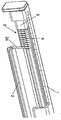
도 1은 중립 위치에 있는 본 발명에 따른 댐퍼를 구비한 가구 풀아웃 가이드의 부분 단면 사시도이며,
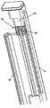
도 2는 부분적으로 압축된 댐퍼를 구비한, 도 1에 따른 도면이며,
도 3은 최대로 압축된 댐퍼를 구비한 도 1에 따른 도면이며,
도 4는 작동 레일의 단부 플러그에 체결되는 댐퍼의 부분 단면 사시도이다.1 is a partial cross-sectional perspective view of a furniture pull-out guide with a damper according to the invention in a neutral position,
FIG. 2 is a view according to FIG. 1 with a partially compressed damper,
3 is a view according to FIG. 1 with a maximally compressed damper, FIG.
4 is a partial cross-sectional perspective view of the damper fastened to the end plug of the actuation rail;
도 1 내지 도 3에서, 도면부호 "1"은 가구 풀아웃 가이드의 작동 레일을 표시하며, 작동 레일은 이중 화살표(A)의 방향으로 풀아웃-연장 중앙 레일(2)에 대해 종방향으로 변위가능하다.1 to 3, reference numeral 1 denotes the actuation rail of the furniture pull-out guide, which acts in the longitudinal direction with respect to the pull-out
중앙 레일(2)은 공지된 방식으로 고정되게 장착된 바디 레일에 대해 변위가능하며, 중앙 레일은 공지된 것이므로 더 상세하게 도시하지 않았다.The
이용될 때 가구 풀아웃 부분을 운반하는 작동 레일(1)은 도 1 내지 도 3에 따른 도시된 위치에서 가구 바디로부터 좌측으로 당겨지며 가구 바디 내로 우측으로 역으로 가압되는 것이 더 용이한 배향을 위해 언급되는 것이 필요하다.The operating rail 1 carrying the furniture pull-out part when used is pulled from the furniture body to the left in the position shown in accordance with FIGS. 1 to 3 and for an orientation which is easier to press back into the furniture body to the right. It is necessary to be mentioned.
본 발명에 따른 댐퍼(3)는 전방 단부에서 작동 레일(1)로 연결된다. 이러한 댐퍼(3)는 중앙 레일(2)의 변위 경로에 배치되어 작동 레일(1)의 삽입 동안 중앙 레일(2)의 전방 정면 측부(2a)와 만나며, 이는 가구 풀아웃 부분에서의 가압에 대응한다. 가구 바디로부터 가구 풀아웃 부분의 당김에 대응하여, 작동 레일(1)이 당겨질 때, 댐퍼(3)는 중앙 레일(2)로부터 완전히 멀리 이동한다.The damper 3 according to the invention is connected to the working rail 1 at the front end. This damper 3 is arranged in the displacement path of the
선택적으로, 단부-위치 댐퍼로서 이용되는 댐퍼(3)는 풀-인 메카니즘을 구비한 소정의 풀아웃-연장 중앙 레일(2)이 없는 가구 풀 아웃의 경우, 바디 레일의 정면 측부와 만난다.Optionally, the damper 3, which is used as an end-position damper, meets the front side of the body rail in the case of a furniture pull-out without any pull-out
댐퍼(3)는 벨로우즈의 형태로 배치되고 외부가 완전히 밀봉되고 기상 매체로 채워지는 챔버를 형성하는 하우징(4)으로 이루어진다. 벨로우즈(4)는 따라서 중공형 바디로서 배치되고 외부를 향하여 완전히 밀봉된다. 기상 매체, 바람직하게는 공기가 상기 중공형 바디의 내부에 배치된다.The damper 3 consists of a housing 4 which is arranged in the form of a bellows and forms a chamber in which the outside is completely sealed and filled with a gaseous medium. The bellows 4 is thus arranged as a hollow body and completely sealed outwards. A gaseous medium, preferably air, is disposed inside the hollow body.
벨로우즈(4)는 플라스틱으로 제조된다.The bellows 4 is made of plastic.
도 4에 특별히 도시된 바와 같이, 작동 레일(1)의 전방면에 삽입될 수 있는 단부 플러그(5)로 체결된다. 단부 플러그(5)에서 벨로우즈(4)의 체결은 전방 단부 상의 벨로우즈(4)에 부착되는 핀(7)의 보어 구멍 같이 단부 플러그(5)의 보어 구멍을 관통하는 볼트(6)에 의해 발생된다.As shown in particular in FIG. 4, it is fastened with an
중앙 레일(2)의 정면 단부(2a)와 벨로우즈(4)의 마주하는 정면 측면(4a) 사이의 거리가 작동 레일(1)의 수축 동안 감소될 때, 벨로우즈(4)는 중앙 레일(2)의 정면 측면(2a)과 만나게 된다. 두 개의 레일(1 및 2)이 서로에 대해 함께 추가로 가압될 때, 이는 벨로우즈(4)의 내부에 배치되는 기상 매체의 압축에 의해 동반되는, 벨로우즈(4)의 축방향 감소를 초래하게 된다. 작동 레일(1)의 유입 속도는 따라서 감소되어 작동 레일(1)이 단부 정지부 등과 만날 때 노이즈가 최소화된다.When the distance between the front end 2a of the
예를 들면, 폐쇄된 서랍의 위치에 대응하는 푸쉬-인 상태에서, 벨로우즈(4)는 도 3에 도시되어 보여진 바와 같이 최대로 압축되어 그 안의 기상 매체가 최대로 압축되고 따라서 가장 높은 달성가능한 내부 압력 하에 있게 된다. 작동 레일(1)이 중앙 레일(2)에 대해 좌측으로 변위되는 것을 의미하는, 서랍이 다시 개방될 때, 기상 매체는 벨로우즈(4)의 내부에서 다시 이완될 수 있어 도 1에 도시된 바와 같이, 벨로우즈(4)가 원래 상태로 다시 역으로 이동한다.For example, in the push-in state corresponding to the position of the closed drawer, the bellows 4 is maximally compressed as shown in FIG. 3 so that the gaseous medium therein is maximally compressed and thus the highest achievable interior Under pressure. When the drawer is opened again, which means that the operating rail 1 is displaced to the left with respect to the
비록 소정의 변형력이 벨로우즈(4)의 압축을 위해 인가되고 각각의 복원력이 벨로우즈의 완화시 효과적으로 되겠지만, 댐퍼(3)의 댐핑 효과는 따라서 상술된 구성의 결과로서 벨로우즈(4) 내의 기상 매체의 압축에 의해서만 사실상 결정된다. 복원력은 기능과의 관련성이 적으며 벨로우즈(4)에 영향을 미치는 변형 및 복원력이 마침내 0에 접근할 때 댐퍼(3)는 또한 기능을 유지한다.Although a predetermined strain force is applied for the compression of the bellows 4 and each restoring force will be effective in mitigating the bellows, the damping effect of the damper 3 is thus compressed in the gaseous medium in the bellows 4 as a result of the above-described configuration. It is virtually determined only by The restoring force is less relevant to the function and the damper 3 also retains its function when the deformation and restoring force affecting the bellows 4 finally approaches zero.
가구 풀아웃 가이드의 작동 레일(1)과 중앙 레일(2) 사이의 협동은 도시된 실시예에서 설명되었다. 댐퍼(3)는 또한 중앙 레일(2)이 없고 작동 레일(1)이 고정되게 장착된 바디 레일 상에서 직접 안내될 때 명백하게 유용하게 이용될 수 있다. 댐퍼(3)는 이어서 선택적으로 또한 바디 레일의 후방 단부 영역에 체결될 수 있고 작동 레일(1)의 후방 정면 단부에 의해 가압될 수 있다.The cooperation between the actuating rail 1 and the
벨로우즈(4)를 자체-수축 플라스틱 재료로 제조하여 충전재로서 사실상 비압축성 매체를 이용하는 것이 또한 명백히 가능하다.It is also obviously possible to make the bellows 4 from a self-shrink plastic material to use a substantially incompressible medium as filler.
댐핑 효과를 달성하기 위한 개방-셀(open-cell) 탄성 재료로 벨로우즈(4)를 채우는 것이 또한 가능하다.It is also possible to fill the bellows 4 with an open-cell elastic material to achieve a damping effect.
더욱이, 소정의 포옴(foam)의 기계적 스프링의 이용은 댐핑 효과를 달성하기 위해 가능하다.Moreover, the use of a mechanical foam of some foam is possible to achieve a damping effect.
소정의 형상의 인터록킹(interlocking), 마찰 또는 재료 연결은 단부 플러그(5)와 댐퍼(3) 사이의 연결로서 가능하다.Interlocking, frictional or material connections of any shape are possible as the connection between the
단부 플러그(5) 및 댐퍼(3)가 2-성분 사출 성형 공정에서 일체로 형성되는 것이 추가 실시예에서 추가로 제공된다. 이러한 방식으로, 벨로우즈(4)는 더 큰 탄성의 플라스틱 및 더 높은 경도의 플라스틱의 단부 플러그 부분으로 이루어진다.It is further provided in a further embodiment that the
하우징이 밀봉 챔버로서 배치되고 예를 들면 자체-수축 탄성 재료로 제조되는 추가의 실시예가 추가로 제공된다. 이러한 실시예에서, 하우징 또는 벨로우즈(4)는 비압축성 또는 거의 비압축성 매체로 채워질 수 있다. 선택적으로, 하우징 또는 벨로우즈(4)는 또한 개방-셀 탄성 재료로 채워질 수 있다. 벨로우즈(4)는 인터록킹, 마찰 또는 재료 연결 방식으로 단부 플러그(4)와 적절히 연결된다. 더욱이, 벨로우즈는 또한 작동 레일(1)의 단부 플러그(5)와 연결될 수 있다. 벨로우즈(4)가 일체형 방식으로 배치될 때 특히 유용하다. 벨로우즈(4) 및 단부 플러그(5)가 하나의 유닛으로서 일체로 제조되는 것이 또한 가능하다. 힘이 기계적 스프링에 의해 인가되는 것이 또한 가능하다.Further embodiments are provided in which the housing is arranged as a sealing chamber and is made of, for example, a self-shrinkable elastic material. In this embodiment, the housing or bellows 4 may be filled with incompressible or almost incompressible media. Optionally, the housing or bellows 4 can also be filled with an open-cell elastic material. The bellows 4 is suitably connected with the end plug 4 in an interlocking, frictional or material connection manner. Furthermore, the bellows can also be connected with the
Claims (15)
상기 댐퍼(3)는 상기 작동 레일(1) 또는 바디 레일에 체결되며 중앙 레일(2) 또는 작동 레일(1)의 변위 경로에 배치되고, 적어도 상기 작동 레일(1)의 변위 방향으로 탄성적으로 변형될 수 있으며, 풀아웃 방향으로의 힘을 흡수하는 챔버를 포함하는 하우징으로 이루어지는 것을 특징으로 하는,
가구 풀아웃 가이드용 댐퍼.
In the damper 30 for furniture pull-out guide comprising a body rail and an operating rail 1 and optionally a pull-out-extending central rail 2,
The damper 3 is fastened to the actuation rail 1 or the body rail and is disposed in the displacement path of the center rail 2 or the actuation rail 1, and at least elastically in the displacement direction of the actuation rail 1. It can be deformed, characterized in that consisting of a housing including a chamber that absorbs the force in the pull-out direction,
Damper for furniture pull-out guides.
상기 하우징은 플라스틱으로 제조되는 것을 특징으로 하는,
가구 풀아웃 가이드용 댐퍼.
The method of claim 1,
Characterized in that the housing is made of plastic,
Damper for furniture pull-out guides.
상기 하우징은 벨로우즈(4)로서 배치되는 것을 특징으로 하는,
가구 풀아웃 가이드용 댐퍼.
The method according to claim 1 or 2,
The housing is characterized in that it is arranged as bellows 4,
Damper for furniture pull-out guides.
상기 하우징은 밀봉된 챔버로서 배치되는 것을 특징으로 하는,
가구 풀아웃 가이드용 댐퍼.
The method according to claim 1 or 2,
The housing is arranged as a sealed chamber,
Damper for furniture pull-out guides.
상기 하우징은 자체-수축 탄성 재료로 제조되는 것을 특징으로 하는,
가구 풀아웃 가이드용 댐퍼.
The method according to claim 1 or 2,
Characterized in that the housing is made of a self-shrinkable elastic material,
Damper for furniture pull-out guides.
상기 벨로우즈(4)는 단면이 직사각형, 바람직하게는 정사각형인 것을 특징으로 하는,
가구 풀아웃 가이드용 댐퍼.
6. The method according to any one of claims 1 to 5,
The bellows 4 is characterized in that the cross section is rectangular, preferably square,
Damper for furniture pull-out guides.
상기 하우징 또는 벨로우즈(4)는 공기로 채워지는 것을 특징으로 하는,
가구 풀아웃 가이드용 댐퍼.
The method according to any one of claims 1 to 6,
Said housing or bellows 4 is filled with air,
Damper for furniture pull-out guides.
상기 하우징 또는 벨로우즈(4)는 비 압축성 또는 거의 비 압축성 재료로 채워지는 것을 특징으로 하는,
가구 풀아웃 가이드용 댐퍼.
The method according to any one of claims 1 to 7,
The housing or bellows 4 is characterized in that it is filled with an incompressible or almost incompressible material,
Damper for furniture pull-out guides.
상기 하우징 또는 벨로우즈(4)는 개방-셀(open-cell) 탄성 재료로 채워지는 것을 특징으로 하는,
가구 풀아웃 가이드용 댐퍼.
The method according to any one of claims 1 to 8,
The housing or bellows 4 is characterized in that it is filled with an open-cell elastic material,
Damper for furniture pull-out guides.
상기 벨로우즈(4)는 마찰, 인터록킹 또는 재료 연결 방식으로 단부 플러그(5)와 연결되는 것을 특징으로 하는,
가구 풀아웃 가이드용 댐퍼.
The method according to any one of claims 1 to 9,
The bellows 4 is characterized in that it is connected with the end plug 5 in a friction, interlocking or material connection manner,
Damper for furniture pull-out guides.
상기 벨로우즈(4)는 상기 작동 레일(1)의 단부 플러그(5)로 연결되는 것을 특징으로 하는,
가구 풀아웃 가이드용 댐퍼.
The method according to any one of claims 1 to 10,
The bellows 4 is characterized in that it is connected to the end plug 5 of the actuation rail 1,
Damper for furniture pull-out guides.
상기 벨로우즈(4)가 일체로 제조되는 것을 특징으로 하는,
가구 풀아웃 가이드용 댐퍼.
The method according to any one of claims 1 to 11,
Characterized in that the bellows (4) is integrally manufactured,
Damper for furniture pull-out guides.
상기 벨로우즈(4) 및 상기 단부 플러그(5)는 유닛으로서 일체로 제조되는 것을 특징으로 하는,
가구 풀아웃 가이드용 댐퍼.
The method according to any one of claims 1 to 12,
Said bellows 4 and said end plug 5 are manufactured integrally as a unit,
Damper for furniture pull-out guides.
상기 힘은 기계적 스프링에 의해 인가되는 것을 특징으로 하는,
가구 풀아웃 가이드용 댐퍼.
The method of claim 1,
The force is applied by a mechanical spring,
Damper for furniture pull-out guides.
상기 벨로우즈(4)는 볼트(6)에 의해 상기 단부 플러그(5)와 연결되고, 상기 볼트(6)는, 또한 단부 측부에서 상기 벨로우즈(4)에 부착되는 핀(7)의 보어 홀을 통과하는 것과 같이, 상기 단부 플러그(5)의 보어 홀을 통과하는 것을 특징으로 하는,
가구 풀아웃 가이드용 댐퍼.The method according to any one of claims 1 to 14,
The bellows 4 is connected to the end plug 5 by a bolt 6, which bolt 6 also passes through a bore hole of a pin 7 attached to the bellows 4 at the end side. As it is, characterized in that passing through the bore hole of the end plug (5),
Damper for furniture pull-out guides.
Applications Claiming Priority (2)
| Application Number | Priority Date | Filing Date | Title |
|---|---|---|---|
| DE202008006755.3 | 2008-05-19 | ||
| DE202008006755U DE202008006755U1 (en) | 2008-05-19 | 2008-05-19 | damper |
Publications (1)
| Publication Number | Publication Date |
|---|---|
| KR20110043537A true KR20110043537A (en) | 2011-04-27 |
Family
ID=40812806
Family Applications (1)
| Application Number | Title | Priority Date | Filing Date |
|---|---|---|---|
| KR1020107028632A KR20110043537A (en) | 2008-05-19 | 2009-03-04 | Damper |
Country Status (10)
| Country | Link |
|---|---|
| EP (1) | EP2276377B1 (en) |
| JP (1) | JP5453619B2 (en) |
| KR (1) | KR20110043537A (en) |
| CN (1) | CN102036585B (en) |
| AU (1) | AU2009250025A1 (en) |
| DE (1) | DE202008006755U1 (en) |
| ES (1) | ES2533845T3 (en) |
| RU (1) | RU2503389C2 (en) |
| TW (1) | TW201006410A (en) |
| WO (1) | WO2009141174A1 (en) |
Families Citing this family (9)
| Publication number | Priority date | Publication date | Assignee | Title |
|---|---|---|---|---|
| DE202008003328U1 (en) * | 2007-10-02 | 2009-02-12 | Paul Hettich Gmbh & Co. Kg | Pull-out guide with a self-closing device |
| AT512897B1 (en) * | 2012-10-02 | 2013-12-15 | Fulterer Gmbh | Pull-out guide for a piece of furniture which can be pulled out of a furniture carcass |
| DE102012109751B4 (en) * | 2012-10-12 | 2023-08-03 | Paul Hettich Gmbh & Co. Kg | Pull-out guide for a pull-out piece of furniture and furniture |
| AT513608B1 (en) * | 2013-03-12 | 2014-06-15 | Fulterer Gmbh | Pull-out guide for a piece of furniture which can be pulled out of a furniture carcass |
| DE202014101504U1 (en) | 2014-03-31 | 2015-07-06 | Grass Gmbh & Co. Kg | Device for influencing the movement of a furniture part and furniture part |
| DE202015103067U1 (en) | 2015-06-11 | 2016-09-14 | Paul Hettich Gmbh & Co. Kg | Pull-out guide and household appliance |
| FR3039107B1 (en) * | 2015-07-22 | 2017-09-01 | Cera Aps | AUTOMOTIVE VEHICLE LUGGAGE COMPARTMENT REPAIR SYSTEM |
| CN109826892B (en) * | 2019-03-05 | 2020-10-30 | 北京航空航天大学 | Repeatedly-usable multistable energy-absorbing array combined structure |
| DE102022105787A1 (en) | 2022-03-11 | 2023-09-14 | Schock Metallwerk Gmbh. | Excerpt guide |
Family Cites Families (20)
| Publication number | Priority date | Publication date | Assignee | Title |
|---|---|---|---|---|
| FR1116627A (en) * | 1954-12-28 | 1956-05-09 | Door stopper | |
| DE3108862A1 (en) * | 1981-03-09 | 1982-09-23 | Rudolf 6466 Gründau Walther | Door buffer |
| JPS61122437U (en) * | 1985-01-18 | 1986-08-01 | ||
| JPS62199332U (en) * | 1986-06-09 | 1987-12-18 | ||
| DE8710830U1 (en) * | 1987-08-07 | 1987-09-24 | Paul Hettich Gmbh & Co, 4983 Kirchlengern, De | |
| JPH108823A (en) * | 1996-06-24 | 1998-01-13 | Noriaki Nakakura | Door stop |
| DE19717937A1 (en) * | 1996-11-08 | 1998-05-20 | Grass Ag | Braking and damping element for moving furniture parts |
| DE29803210U1 (en) * | 1998-02-24 | 1998-04-16 | Hettich Paul Gmbh & Co | Drawer run |
| DE29913854U1 (en) * | 1999-08-09 | 1999-10-07 | Salice Arturo Spa | Brake deceleration device for doors, windows or the like. |
| IT250443Y1 (en) * | 2000-09-19 | 2003-09-10 | Salice Arturo Spa | DEVICE FOR THE DECELERATED CLOSURE OF SLIDING FURNITURE PARTS |
| JP2003158391A (en) * | 2001-11-19 | 2003-05-30 | Kawamura Electric Inc | Rack |
| DE20204860U1 (en) | 2002-03-26 | 2003-07-31 | Alfit Ag Goetzis | Drawer pull-out guides with automatic retraction with integrated damping |
| EP1481611A1 (en) * | 2003-05-28 | 2004-12-01 | Miguel Angel Rioja Calvo | Damping device for absoring shocks between furniture pieces |
| DE502005000561D1 (en) * | 2004-02-17 | 2007-05-24 | Rioja Calvo Miguel Angel D | Damping device for furniture |
| JP4529873B2 (en) * | 2005-01-27 | 2010-08-25 | 株式会社デンソー | Air conditioning unit |
| JP2006250339A (en) * | 2005-03-14 | 2006-09-21 | Tokai Rubber Ind Ltd | Fluid encapsulated type vibration isolating device |
| JP2006275249A (en) * | 2005-03-30 | 2006-10-12 | Arai Pump Mfg Co Ltd | Shock absorber |
| US20070119549A1 (en) * | 2005-11-30 | 2007-05-31 | Weiland William R | Sliding panel interlock |
| DE202007009773U1 (en) * | 2007-07-13 | 2007-09-20 | ACE Stoßdämpfer GmbH | Braking and damping device for damping and decelerating the kinetic energy of mobile masses, e.g. Drawers, furniture doors, furniture flaps, swivel and revolving doors or the like. |
| DE202007014389U1 (en) * | 2007-10-16 | 2008-03-13 | Paul Hettich Gmbh & Co. Kg | pull-out guide |
-
2008
- 2008-05-19 DE DE202008006755U patent/DE202008006755U1/en not_active Expired - Lifetime
-
2009
- 2009-03-04 EP EP09749664.0A patent/EP2276377B1/en not_active Not-in-force
- 2009-03-04 AU AU2009250025A patent/AU2009250025A1/en not_active Abandoned
- 2009-03-04 KR KR1020107028632A patent/KR20110043537A/en not_active Application Discontinuation
- 2009-03-04 CN CN200980118404.8A patent/CN102036585B/en not_active Expired - Fee Related
- 2009-03-04 JP JP2011509904A patent/JP5453619B2/en not_active Expired - Fee Related
- 2009-03-04 ES ES09749664.0T patent/ES2533845T3/en active Active
- 2009-03-04 RU RU2010150874/12A patent/RU2503389C2/en not_active IP Right Cessation
- 2009-03-04 WO PCT/EP2009/052562 patent/WO2009141174A1/en active Application Filing
- 2009-03-06 TW TW098107297A patent/TW201006410A/en unknown
Also Published As
| Publication number | Publication date |
|---|---|
| WO2009141174A1 (en) | 2009-11-26 |
| AU2009250025A1 (en) | 2009-11-26 |
| TW201006410A (en) | 2010-02-16 |
| JP5453619B2 (en) | 2014-03-26 |
| CN102036585A (en) | 2011-04-27 |
| EP2276377B1 (en) | 2014-12-31 |
| RU2010150874A (en) | 2012-06-27 |
| DE202008006755U1 (en) | 2009-10-22 |
| ES2533845T3 (en) | 2015-04-15 |
| EP2276377A1 (en) | 2011-01-26 |
| JP2011520539A (en) | 2011-07-21 |
| RU2503389C2 (en) | 2014-01-10 |
| CN102036585B (en) | 2014-06-25 |
Similar Documents
| Publication | Publication Date | Title |
|---|---|---|
| KR20110043537A (en) | Damper | |
| JP5284801B2 (en) | General-purpose impact prevention device | |
| US8419142B2 (en) | Drawer guide | |
| JP4648390B2 (en) | Furniture door closing shock absorber | |
| JP6734888B2 (en) | Drive for movable furniture | |
| TW575719B (en) | Air damper for movable furniture parts | |
| US20180295991A1 (en) | Drawer pull-out guide | |
| JP2008116051A (en) | Braking/damping device for movable part of furniture | |
| JP4675145B2 (en) | Shock absorber and drawer | |
| KR101666780B1 (en) | Damper for furniture | |
| WO2008139298A8 (en) | Device for securing a soft ending of the opening movement of a drawer | |
| EP2546443A1 (en) | Door damper buffer | |
| JP5671733B2 (en) | Drawer guide opening / closing device and drawer guide | |
| US20190008276A1 (en) | Furniture drive | |
| US20060207057A1 (en) | Damping device for pieces of furniture with improved compensation system of volume variations | |
| JP2008032206A (en) | Drawer air damper | |
| US20160120310A1 (en) | Device for braking a movement | |
| US10513275B2 (en) | Selective cushioning apparatus assembly | |
| CN108166880B (en) | Furniture sliding door buffer | |
| US8025135B1 (en) | Hydraulic damping device for drawer | |
| JP3196135U (en) | Self-closing slide rail kit | |
| CN110869574B (en) | Furniture buffer | |
| CN207863698U (en) | A kind of buffer for furniture sliding door | |
| CN108567251B (en) | Return mechanism for movable furniture component | |
| KR200328303Y1 (en) | Cushion damper for door |
Legal Events
| Date | Code | Title | Description |
|---|---|---|---|
| A201 | Request for examination | ||
| E902 | Notification of reason for refusal | ||
| E601 | Decision to refuse application |