KR20100117597A - Security element - Google Patents
Security element Download PDFInfo
- Publication number
- KR20100117597A KR20100117597A KR1020107017453A KR20107017453A KR20100117597A KR 20100117597 A KR20100117597 A KR 20100117597A KR 1020107017453 A KR1020107017453 A KR 1020107017453A KR 20107017453 A KR20107017453 A KR 20107017453A KR 20100117597 A KR20100117597 A KR 20100117597A
- Authority
- KR
- South Korea
- Prior art keywords
- security element
- scattering
- layer
- code
- security
- Prior art date
Links
Images


Classifications
-
- B—PERFORMING OPERATIONS; TRANSPORTING
- B42—BOOKBINDING; ALBUMS; FILES; SPECIAL PRINTED MATTER
- B42D—BOOKS; BOOK COVERS; LOOSE LEAVES; PRINTED MATTER CHARACTERISED BY IDENTIFICATION OR SECURITY FEATURES; PRINTED MATTER OF SPECIAL FORMAT OR STYLE NOT OTHERWISE PROVIDED FOR; DEVICES FOR USE THEREWITH AND NOT OTHERWISE PROVIDED FOR; MOVABLE-STRIP WRITING OR READING APPARATUS
- B42D25/00—Information-bearing cards or sheet-like structures characterised by identification or security features; Manufacture thereof
- B42D25/40—Manufacture
- B42D25/45—Associating two or more layers
- B42D25/465—Associating two or more layers using chemicals or adhesives
- B42D25/47—Associating two or more layers using chemicals or adhesives using adhesives
-
- B—PERFORMING OPERATIONS; TRANSPORTING
- B42—BOOKBINDING; ALBUMS; FILES; SPECIAL PRINTED MATTER
- B42D—BOOKS; BOOK COVERS; LOOSE LEAVES; PRINTED MATTER CHARACTERISED BY IDENTIFICATION OR SECURITY FEATURES; PRINTED MATTER OF SPECIAL FORMAT OR STYLE NOT OTHERWISE PROVIDED FOR; DEVICES FOR USE THEREWITH AND NOT OTHERWISE PROVIDED FOR; MOVABLE-STRIP WRITING OR READING APPARATUS
- B42D25/00—Information-bearing cards or sheet-like structures characterised by identification or security features; Manufacture thereof
- B42D25/20—Information-bearing cards or sheet-like structures characterised by identification or security features; Manufacture thereof characterised by a particular use or purpose
- B42D25/29—Securities; Bank notes
-
- B—PERFORMING OPERATIONS; TRANSPORTING
- B42—BOOKBINDING; ALBUMS; FILES; SPECIAL PRINTED MATTER
- B42D—BOOKS; BOOK COVERS; LOOSE LEAVES; PRINTED MATTER CHARACTERISED BY IDENTIFICATION OR SECURITY FEATURES; PRINTED MATTER OF SPECIAL FORMAT OR STYLE NOT OTHERWISE PROVIDED FOR; DEVICES FOR USE THEREWITH AND NOT OTHERWISE PROVIDED FOR; MOVABLE-STRIP WRITING OR READING APPARATUS
- B42D25/00—Information-bearing cards or sheet-like structures characterised by identification or security features; Manufacture thereof
Abstract
본 발명은 물체의 식별 및 인증을 위한 보안 소자(1)에 관한 것이다. 본 발명에 의한 소자는 물체에 부착될 수 있는 셀프-접착 라벨의 형태로 존재한다. 본 발명에 의한 소자는 보안 소자가 임의의 손상 없이 물체로부터 제거되는 것을 방지하는 특징을 갖는다. 보안 소자는 식별을 위한 광학 코드(2)를 가지며, 전자기 방사의 조사시 보안 소자의 산란 영역(3)이 특징적인 산란 신호를 생성하는 인증을 가능케 하는 랜덤 제조 관련 특징을 제공한다. 또한, 본 발명은 물체의 식별 및 인증 및 위조 방지를 위한 보안 소자의 사용 및, 본 발명에 의한 보안 소자에 기초한 물체의 식별 및 인증 방법에 관한 것이다.The present invention relates to a security element (1) for the identification and authentication of an object. The device according to the invention is in the form of a self-adhesive label which can be attached to an object. The device according to the invention has the feature of preventing the security element from being removed from the object without any damage. The security element has an optical code 2 for identification and provides a random manufacturing related feature that enables the scattering area 3 of the security element to generate a characteristic scattering signal upon irradiation of electromagnetic radiation. The present invention also relates to the use of a security element for identification and authentication of an object and the prevention of forgery, and to a method of identification and authentication of an object based on the security element according to the invention.
Description
본 발명은 보안 소자, 물체의 식별 및 인증 및 또한 위조 방지를 위한 보안 소자의 사용 및, 본 발명에 의한 보안 소자에 기초한 위조 및 물체의 식별 및 인증 방법에 관한 것이다.The present invention relates to a security element, to the identification and authentication of an object and also to the use of a security element for preventing forgery, and to a method of identification and authentication of a forgery and an object based on the security element according to the invention.
광학 방법에 의한 물체의 자동 인식은 종래 기술에 공지되어 있다. 모든 사람들은, 예를 들면 상품 및/또는 포장에 적용되어 있으며 상품의 기기 식별로 예를 들면 가격을 알아낼 수 있도록 하는 바아 코드에 익숙하다.Automatic recognition of objects by optical methods is known in the art. Everyone is familiar with bar codes, for example, applied to goods and / or packaging and allowing the identification of the goods, for example, by price.
바아 코드의 공지의 대표적인 일례로는 국제 규격 ISO/IEC 15420에서 정의하는 EAN 8 코드를 들 수 있다. 이는 폭이 상이한 바아 및 간극의 형태로 8 개의 숫자 서열을 코드화한다. 일반적으로, 바아는 예를 들면 식별하고자 하는 물체의 포장체인 백색 캐리어에 또는 물체 자체에 흑색 인쇄 잉크를 사용하여 인쇄된다.A representative example of a known bar code is the EAN 8 code defined in the international standard ISO / IEC 15420. It encodes eight numeric sequences in the form of bars and gaps of different widths. In general, the bar is printed using black printing ink, for example on a white carrier which is a package of the object to be identified or on the object itself.
설명한 EAN 8 코드 이외에, 숫자뿐 아니라 문자, 특수 문자 및 제어 문자도 코드화하는 추가의 각종 바아 코드가 존재한다. 게다가, 일부 코드는 신호 전달에서의 오류를 검출하고 그리고 부분적으로는 심지어 정정하도록 하는 오류 검출 및 오류 정정 문자를 포함한다. 바아 코드의 추가의 개발은 정보가 1차원이 아닌 2차원으로 광학적으로 코드화된 2D 코드이다. 이른바 매트릭스 코드는 2D 코드의 하부군을 형성한다. 공지된 대표적인 일례로는 국제 규격 ISO/IEC 16022에서 정의한 데이타 매트릭스 코드가 있다.In addition to the EAN 8 codes described, there are a variety of additional bar codes that encode not only numbers but also letters, special characters and control characters. In addition, some codes include error detection and error correction characters that allow for detection and, in part, even correction of errors in signaling. Further development of the bar code is a 2D code in which the information is optically coded in two dimensions rather than in one dimension. So-called matrix codes form a subgroup of 2D codes. An example of a known example is a data matrix code defined in the international standard ISO / IEC 16022.
기기-판독형 광학 코드, 예컨대 전술한 바아 코드, 2D 코드 및 매트릭스 코드뿐 아니라, OCR-텍스트(OCR=광학 문자 인식) 또는 유사한 광학적 기기-판독형 코드는 이하에서 광학 코드라는 포괄적 용어에 포함시키고자 한다.Instrument-readable optical codes such as bar codes, 2D codes and matrix codes as described above, as well as OCR-text (OCR = optical character recognition) or similar optical instrument-readable codes, are hereafter incorporated into the generic term optical code. Let's do it.
광학 코드는 단순하게 그리고 비용면에서 매우 효율적으로 (인쇄) 생성될 수 있으며, 검출이 신속하며 강력하다. 이는 이상적으로는 물체의 식별에 적절하다. 특히, 광학 코드는 물체 추적(추적 및 트레이스)에 적절하다. 이러한 경우, 예를 들면 물체는 물류 사슬에서의 모든 스테이션에서 식별될 수 있으며, 이에 의하여 물류 사슬의 하나의 스테이션에서 또다른 스테이션으로의 물체의 이동을 추적할 수 있도록 물체에는 고유의 번호가 할당된다.Optical codes can be produced simply and cost-effectively (printed), and the detection is fast and powerful. This is ideally suited for the identification of objects. In particular, optical codes are suitable for object tracking (tracking and tracing). In this case, for example, the object can be identified at every station in the logistics chain, whereby the object is assigned a unique number so that it can track the movement of the object from one station to another station in the logistics chain. .
그러나, 광학 코드는 단순한 방식으로 복사 및 재현될 수 있어서 위조 방지를 제공하지는 않는다.However, optical codes can be copied and reproduced in a simple manner and do not provide forgery protection.
위조에 대한 안전을 위하여 최근에는 신분증, 지폐, 제품 등에는 특수한 지식 및/또는 높은 기술적 복잡성을 사용하여서만 모사할 수 있는 소자가 제공된다. 이와 같은 소자를 본 명세서에서는 보안 소자로 지칭한다. 보안 소자는 보호하고자 하는 물체에 분리 불가하게 연결되는 것이 바람직하다. 보안 소자를 물체로부터 분리하고자 하는 시도는 보안 소자가 파괴되어 보안 소자의 오용을 방지할 수 있다.For the sake of security against counterfeiting, identification cards, bills, products, etc. have recently been provided with devices that can only be simulated using special knowledge and / or high technical complexity. Such an element is referred to herein as a security element. The security element is preferably inseparably connected to the object to be protected. Attempts to detach the security element from the object can destroy the security element and prevent misuse of the security element.
물체의 진위성은 1 이상의 보안 소자의 존재에 기초하여 체크할 수 있다. 물체 진위성의 체크 방법을 본 명세서에서는 인증으로 지칭한다.The authenticity of the object can be checked based on the presence of one or more security elements. The method of checking object authenticity is referred to herein as authentication.
광학 보안 소자, 예컨대 워터마크, 특수 잉크, 길로쉐 패턴, 마이크로스크립트(microscript) 및 홀로그램이 전세계적으로 사용되고 있다. 그러나, 문서 보호에만 전적으로 적절하지는 않은 광학 보안 소자에 대하여서는 문헌[Rudolf L. van Renesse, Optical Document Security, Third Edition, Artech House Boston/London, 2005 (pp.63-259)]에 보고되어 있다.Optical security elements such as watermarks, special inks, guilloche patterns, microscripts and holograms are used worldwide. However, optical security devices that are not entirely appropriate for document protection are reported in Rudolf L. van Renesse, Optical Document Security , Third Edition, Artech House Boston / London, 2005 (pp. 63-259).
WO2005/088533 A1에는 특징적인 표면 구조에 기초하여 물체를 식별 및 인증할 수 있는 방법이 기재되어 있다. 이러한 경우에서, 이 방법은 예를 들면 물체에 연결되어 있는 보안 소자와 같은 추가의 수단을 사용하지 않고 실시한다. 이 방법에서는, 레이저 비임을 물체의 표면 위에 집속시키고, 표면을 따라 이동시키며(스캐닝), 표면의 상이한 부위에서 상이한 각도에서 상이한 정도로 산란된 비임은 광검출기에 의하여 검출된다. 검출된 산란 방사는 다양한 각종 소재의 특징이 되며, 물체의 제조중의 랜덤 발생에 기인할 수 있으므로 모방하기에는 매우 어렵다. 예를 들면, 종이형 물체는 제조된 각각의 물체에 대하여 고유한 생산-조절된 섬유 구조체이다. 각각의 물체에 대한 산란 데이타는 데이타베이스에 저장되어 차후의 어느 시점에서 물체를 인증할 수 있다. 물체를 다시 측정하고, 산란 데이타를 저장한 기준 데이타와 비교한다.WO2005 / 088533 A1 describes a method by which an object can be identified and authenticated based on its characteristic surface structure. In this case, the method is carried out without the use of additional means, for example a security element connected to the object. In this method, the laser beam is focused on the surface of the object, moved along the surface (scanning), and the beam scattered to different degrees at different angles at different sites of the surface is detected by the photodetector. The detected scattered radiation is characteristic of a variety of different materials and is very difficult to imitate since it may be due to random occurrence during manufacture of the object. For example, a paperlike object is a production-controlled fibrous structure that is unique for each object produced. Scattering data for each object can be stored in a database to authenticate the object at some later point in time. Measure the object again and compare the scattering data with the stored reference data.
WO2005/088533 A1의 방법에 사용된 물체의 랜덤 특징은 매우 높은 위조 방지력을 야기한다. 그러나, 이 방법의 단점은 검출된 모든 물체의 산란 데이타에 대한 방대한 데이타베이스를 생성하여야만 한다는 점이다. 한편으로, 데이타베이스는 다수의 물체의 산란 데이타의 대량 데이타를 저장하기 위하여서는 저장 용량이 커야만 한다. 다른 한편으로, 정확한 데이타 기록을 찾기 위하여 검출된 산란 데이타는 인증(1:n-대조)에 대한 데이타베이스에서 모든 기준 데이타와 비교하여야만 하기 때문에 데이타베이스에서의 데이타로의 접근 시간은 신속하여야만 한다. 게다가, 모든 물체가 WO2005/088533 A1에 의한 방법에 대하여 접근 가능한 표면을 갖는 것은 아니다.The random feature of the object used in the method of WO2005 / 088533 A1 results in a very high anti-counterfeiting force. However, a disadvantage of this method is that a large database of scattering data of all detected objects must be created. On the other hand, the database must have a large storage capacity in order to store large amounts of scattering data of a plurality of objects. On the other hand, the access time to the data in the database must be fast because the scattering data detected in order to find the correct data record must be compared with all reference data in the database for authentication (1: n-control). In addition, not all objects have an accessible surface for the method according to WO2005 / 088533 A1.
그러므로, 종래 기술은 물체의 식별 및 인증을 위한 각종 방법 및 장치를 제공하는 것으로 확립될 수 있다. 그러나, 광학 코드에 의한 식별을 위한 방법 및 장치는, 식별에 사용되는 특징의 단순 위조 가능성으로 인하여, 위조 방지에는 적절하지 않으며 그리고 물체의 인증에도 적절하지 않다. 반대로, WO2005/088533 A1로부터의 인증 방법이 위조 방지성이 높기는 하나, IT 백-엔드 시스템(데이타베이스, 네트워크)으로 생성되는 대량의 데이타 및 관련 엄격한 요건으로 인하여 식별 및 물체 추적(추적 및 트레이스)에 적절하지 않다. 게다가, 이러한 방법은 모든 물체에 사용될 수 없다.Therefore, the prior art can be established to provide various methods and apparatus for the identification and authentication of objects. However, methods and apparatus for identification by optical codes are not suitable for anti-counterfeiting and not for authentication of objects, due to the simple possibility of forgery of the features used for identification. Conversely, although the authentication method from WO2005 / 088533 A1 is highly anti-counterfeiting, the identification and object tracking (tracking and tracing) due to the large amount of data and related stringent requirements generated by IT back-end systems (databases, networks) Not appropriate). In addition, this method cannot be used for all objects.
그러므로, 공지된 종래 기술로부터 나아가서, 언급한 문제점은 광학 코드의 잇점을 랜덤 특징에 기초한 인증의 잇점과 조합하는 것이다. 언급된 문제점은 다양한 각종 물체에 사용할 수 있으며, 실행이 단순하며, 기존의 IT 인프라스트럭쳐에 구축할 수 있으며, 위조 방지성이 크며, 무엇보다도 비용면에서 효율적인 물체의 식별 및 인증을 위한 해결책을 제공하고자 한다.Therefore, further from the known prior art, the problem mentioned is to combine the benefits of optical codes with the benefits of authentication based on random features. The problems mentioned can be used for a variety of objects, are simple to implement, can be deployed on existing IT infrastructures, are anti-counterfeiting, and above all provide solutions for cost-effective object identification and authentication. I would like to.
놀랍게도, 이러한 문제점은 물체에 비가역적으로 연결되며, 코드 영역 및 산란 영역을 포함하며, 코드 영역은 광학 코드에 기초하여 물체의 식별에 사용되며, 산란 영역은 랜덤으로 제시된 특징으로 인한 특징적인 산란 방사에 기초하여 물체의 인증에 사용되는 보안 소자에 의하여 해결될 수 있는 것으로 밝혀졌다.Surprisingly, this problem is irreversibly connected to the object, includes a code region and a scattering region, the code region is used for identification of the object based on the optical code, and the scattering region is characterized by characteristic scattered radiation due to randomly presented features. It has been found that it can be solved by a security element used for authentication of an object based on.
그러므로, 본 발명은 보안 소자가 물체로부터 비-파괴적으로 분리되는 것을 방지하는 수단을 포함하는, 보안 소자를 물체에 부착시키기 위한 셀프-접착 라벨 형태의 보안 소자에 관한 것으로서, 보안 소자는 코드 영역 및 시각적으로 마킹된 산란 영역을 포함하며, 코드 영역은 광학 코드를 포함하며, 산란 영역은, 산란 영역이 전자기 방사로 조사될 때 보안 소자의 특징이 되는 특유의 산란 신호를 발생시키는 랜덤 분포 및/또는 배향된 산란 중심을 갖는 것을 특징으로 한다.The present invention therefore relates to a security element in the form of a self-adhesive label for attaching a security element to an object, comprising means for preventing the security element from being non-destructively separated from the object, wherein the security element comprises a code region and A visually marked scattering region, wherein the code region comprises an optical code, the scattering region randomly and / or generating a unique scattering signal characteristic of the security element when the scattering region is irradiated with electromagnetic radiation It is characterized by having an oriented scattering center.
식별은 물체를 확실하게 인식하도록 작용하는 방법인 것으로 이해한다. 물체를 확실하게 인식할 경우, 물체는 확실하게 할당될 수 있거나 또는 인식한 물체에 확실한 할당을 실시할 수 있다. 예를 들면 상품(물체)의 인식된 항목은 가격 또는 이의 도착지를 할당할 수 있다. 식별은 물체를 특성화하며 그리고 다른 물체와 구별하는 특징에 기초하여 실시한다.It is understood that identification is a way of acting to reliably recognize an object. If the object is recognized reliably, the object can be reliably assigned or can be surely assigned to the recognized object. For example, a recognized item of merchandise (object) may assign a price or its destination. Identification is based on the characteristics that characterize an object and distinguish it from other objects.
인증은 주장하는 정체를 체크(입증)하는 방법인 것으로 이해한다. 물체, 서류 또는 데이타의 인증은 이들이 진품이며, 즉 변형, 복사 또는 모방되지 않은 원본이라는 것을 확인하는 것이다.I understand that authentication is a way of checking (proving) the alleged identity. Certification of an object, document or data confirms that they are authentic, that is, originals that are not altered, copied or imitated.
식별과 같이, 인증도 또한 물체를 특성화하고 그리고 다른 물체와 구별하는 특징에 기초하여 실시한다.Like identification, authentication is also performed based on the characteristics that characterize an object and distinguish it from other objects.
물체의 식별을 위한 특징 및 물체의 인증을 위한 특징은 본 발명에 의한 보안 소자에 의하여 제공된다.Features for identification of an object and features for authentication of an object are provided by the security element according to the invention.
코드 영역은 식별에 필수적인 특징을 포함한다. 이를 위하여, 코드 영역은 1 이상의 광학 코드, 즉 바아 코드 또는 2D 코드 또는 일부 기타의 광학적 기기-판독형 코드를 포함한다. 광학 코드는 보안 소자에 대하여 고유한 식별 번호를 코드화하는 것이 바람직하다. 식별 번호에 기초하여, 보안 소자 및 예를 들면 데이타베이스에 입력, 기준으로서 특징적인 산란 신호를 포함하는 파일 또는 특정의 기타 현실 또는 가상 물체 사이의 특유의 할당을 생성할 수 있다. 광학 코드는 밝은 배경에 어두운 잉크를 사용하여 인쇄하는 것이 바람직하다. 광학 코드가 어두운 배경에 밝은 잉크로 인쇄된 역 표현도 마찬가지로 가능하다.The code area contains features that are essential for identification. For this purpose, the code region comprises one or more optical codes, ie bar codes or 2D codes or some other optical instrument-readable code. The optical code preferably encodes an identification number unique to the security element. Based on the identification number, a unique assignment between a security element and a file containing a scattering signal characteristic as a reference, for example, a database, or any other real or virtual object can be generated. The optical code is preferably printed using dark ink on a light background. The inverse representation in which the optical code is printed in bright ink on a dark background is likewise possible.
코드 영역의 크기는 사용한 광학 코드의 크기에 의하여 결정된다. 코드 영역의 크기는 일반적으로 50 ㎟ 내지 1,000 ㎟ 범위내가 될 수 있다.The size of the code region is determined by the size of the optical cord used. The size of the code region may generally be in the range from 50
본 발명에 의한 보안 소자는 1보다 많은 코드 영역 및/또는 1보다 많은 광학 코드를 포함하는 것도 가능하다.The security element according to the invention may also comprise more than one code area and / or more than one optical code.
본 발명에 의한 보안 소자의 산란 영역은 전자기 방사로 조사시 특징적인 산란 신호를 생성하는 것을 특징으로 한다. 산란은 산란 영역상에서 번들 형태로 충돌하는 전자기 비임이 상이한 방향으로 다시 반사되는 것을 의미하는 것으로 이해한다. 평행 비임 번들은 평면 거울에 충돌시 반사되며, 이 경우 소정의 각도로 평행 비임 번들로서 다시 반사되며, 산란 영역의 경우에서의 충돌 조사는 다수의 산란 중심에 의하여 상이한 방향으로 다시 반사된다.The scattering area of the security element according to the present invention is characterized by generating a characteristic scattering signal during irradiation with electromagnetic radiation. Scattering is understood to mean that the electromagnetic beams colliding in bundle form on the scattering region are reflected back in different directions. The parallel beam bundle is reflected upon impact on the planar mirror, in which case it is reflected back as a parallel beam bundle at a predetermined angle, and in the case of scattering regions, the collision radiation is reflected back in different directions by multiple scattering centers.
이러한 경우에서, 본 발명에 의한 보안 소자의 산란 영역의 산란 중심은 랜덤 분포 및/또는 배향으로 처리된다. 랜덤 분포 및/또는 배향은 각각의 산란 중심의 위치 및/또는 각각의 산란 중심의 배향이 제조 공정에 의하여 예견 가능한 방식으로 설정될 수 없다는 것을 의미하는 것으로 이해한다. 각각의 산란 중심의 위치 및/또는 배향은 제조 과정중에 랜덤 변동으로 처리된다. 그러므로, 각각의 산란 중심의 위치 및/또는 배향은 단순한 방식으로 재생될 수 없다. 본 발명에 의한 안전 특징에 의하여 제공되는 높은 보호는 매우 복잡하게만 재구성될 수 있다는 사실에 기초한다. 게다가, 랜덤 분포 및/또는 배향은 개별화를 제공하며, 각각의 보안 소자는 전자기 방사의 조사시 특유의, 특징적인 산란 신호를 나타내는 산란 중심의 랜덤 분포 및/또는 배향으로 인하여 고유하게 (개별적으로) 된다.In this case, the scattering centers of the scattering regions of the security element according to the invention are treated with random distribution and / or orientation. Random distribution and / or orientation are understood to mean that the position of each scattering center and / or the orientation of each scattering center cannot be set in a predictable manner by the manufacturing process. The location and / or orientation of each scattering center is treated with random variations during the manufacturing process. Therefore, the position and / or orientation of each scattering center cannot be reproduced in a simple manner. The high protection provided by the safety feature according to the invention is based on the fact that it can only be reconfigured very complicated. In addition, the random distribution and / or orientation provide individualization, and each security element is unique (individually) due to the random distribution and / or orientation of the scattering center, which exhibits a unique, characteristic scattering signal upon irradiation of electromagnetic radiation. do.
본 발명에 의한 보안 소자의 산란 중심은 크기가 1 ㎛2 내지는 0.001 ㎟인 것이 바람직하다. 산란 중심은 안료(예, 이산화티탄) 또는 섬유(예, 셀룰로스)에 의하여 형성될 수 있다.The scattering center of the security element according to the invention preferably has a size of 1 μm 2 to 0.001 mm 2 . Scattering centers may be formed by pigments (eg titanium dioxide) or fibers (eg cellulose).
본 발명에 의한 보안 소자의 산란 중심은 전자기 방사로 조사시 특징적인 산란 방사를 야기하는 생산-조절된 랜덤 섬유 구조체를 갖는 섬유상 소재에 의하여 제공되는 것이 바람직하다. 이와 같은 섬유 구조체는 예를 들면 종이, 판지 또는 직물내에 존재한다. 섬유상 소재로서 종이를 사용하는 것이 바람직하다.The scattering center of the security element according to the invention is preferably provided by a fibrous material having a production-adjusted random fiber structure which causes characteristic scattering radiation upon irradiation with electromagnetic radiation. Such fibrous structures are present, for example, in paper, cardboard or fabric. It is preferable to use paper as the fibrous material.
300 ㎚ 내지 1,000 ㎚ 범위내의 1 이상의 파장을 갖는 전자기 방사는 본 발명에 의한 보안 소자의 산란 영역에 의하여 산란되는 것이 바람직하다.Electromagnetic radiation having a wavelength of at least one in the range of 300 nm to 1,000 nm is preferably scattered by the scattering region of the security element according to the present invention.
본 발명에 의한 보안 소자의 하나의 바람직한 실시태양에서, 산란 영역은 시각적으로 나타난다. 이는 인증이 특징적인 산란 신호에 기초하여 실시되는 위치를 사용자에게 명백하게 제공한다. 그래서, 사용자는 본 발명에 의한 보안 소자의 위치가 기기 인증을 위한 장치에 제시되어야만 한다는 것을 알고 있다. 그러므로, 시각적인 표시는 산란 영역의 검출에 대하여 마킹하는 위치로서 기기 인증을 위한 장치에 의하여 사용될 수 있도록 구성된다.In one preferred embodiment of the security element according to the invention, the scattering area is visually shown. This clearly provides the user with a location where authentication is performed based on the characteristic scattering signal. Thus, the user knows that the location of the security element according to the invention must be presented to the device for device authentication. Therefore, the visual indication is configured to be used by the device for device authentication as a marking location for detection of the scattering area.
산란 영역은 예를 들면 실선으로 프레임 처리하여 시각적으로 나타낼 수 있다.The scattering area may be visually represented by, for example, framing with a solid line.
산란 영역의 크기는 50 ㎟ 내지 1,000 ㎟ 범위내에 있다. 코드 영역은 직사각형 형태로 구체화되는 것이 바람직하며, 이 경우 모서리는 둥글게 처리될 수 있다. 또한, 산란 영역은 정사각형, 둥근형, 타원형, 달걀형, 삼각형, 오각형 또는 일반적으로 n-각형 형태로 구체화되는 것도 가능하다.The size of the scattering area is in the range of 50
하나의 바람직한 실시태양에서, 코드 영역 및 산란 영역은 서로에 대하여 공간적으로 분리되도록 존재한다. 그러나, 이들은 완전 또는 부분 중첩될 수도 있으며, 하나의 영역이 다른 영역을 완벽하게 포함하는 것도 가능하다.In one preferred embodiment, the code region and the scattering region are present to be spatially separated from each other. However, they may be fully or partially overlapped, and it is also possible for one region to completely encompass another region.
본 발명에 의한 보안 소자는 셀프-접착 라벨로서 구체화되어 다수의 각종 물체에 부착될 수 있는 것이 바람직하다. 셀프-접착 라벨은 접착제 접합에 의하여 라벨과 물체 사이의 연결을 가능케 하는 접착층을 갖는 평평한 복합체인 것으로 이해하여야 한다. 여기서, 평평한 바디는 하나의 공간 크기(두께)가 나머지 2 개의 공간 크기(길이, 폭)보다 10 배 이상, 바람직하게는 50 배 이상 작은 바디를 의미하는 것으로 이해하여야 한다. 복합체라는 것은 서로 연결된 2 이상의 소재로 이루어진 바디를 의미하는 것으로 이해하여야 한다. 소재 사이의 연결은 적층 및/또는 접착제 접합에 의하여 생성되는 것이 바람직하다.The security element according to the invention is preferably embodied as a self-adhesive label and can be attached to a number of different objects. Self-adhesive labels are to be understood as being flat composites with an adhesive layer that enables the connection between the label and the object by adhesive bonding. Here, it is to be understood that a flat body means a body in which one space size (thickness) is at least 10 times, preferably at least 50 times smaller than the other two space sizes (length, width). A composite is to be understood as meaning a body composed of two or more materials connected to one another. The connection between the materials is preferably created by lamination and / or adhesive bonding.
본 발명에 의한 보안 소자는 적어도 접착층, 섬유상 소재 함유 층, 인쇄층 및 보호층인 4 개의 층의 층 구조체를 갖는다.The security element according to the present invention has at least four layers of layer structure: an adhesive layer, a fibrous material-containing layer, a printing layer, and a protective layer.
본 발명에 의한 보안 소자는 접착층에 의하여 물체에 연결된다. 접착층은 보안 소자 및 물체 사이를 우수하게 연결하기 위하여 물체의 소재 성질이 변형된다.The security element according to the invention is connected to an object by an adhesive layer. The adhesive layer is modified in the material properties of the object in order to make a good connection between the security element and the object.
섬유상 소재 함유 층은 인쇄 잉크(염료, 안료)를 취하기 위한 것으로 작용하며, 랜덤 분포 및/또는 배향된 산란 중심을 동시에 제공하는 1 이상의 섬유상 소재를 포함한다.The fibrous material containing layer serves to take printing inks (dyes, pigments) and comprises at least one fibrous material which simultaneously provides random distribution and / or oriented scattering centers.
코드 영역내에서 광학 코드를 형성하는 색상 안료 및/또는 염료 및, 적절하게는 추가의 인쇄 화상, 스크립트, 로고 등을 인쇄층내에 도입한다.Color pigments and / or dyes forming optical codes in the code region and, as appropriate, further printed images, scripts, logos and the like are introduced into the printed layer.
본 발명에 의한 보안 소자는 외부와 대면하며, 해로운 환경적 영향(습기, 기계적 응력, UV 방사, 등)으로부터 하부층을 보호하는 보호층을 갖는다. 보호층은 적어도 가시 전자기 방사의 일부에 투과되어 인쇄층이 보일 수 있으며, 기기에 의하여 광학 코드를 판독하고, 전자기 방사로 산란 영역을 방사하고, 특징적인 산란 신호를 수신하도록 한다. 보호층은 300 ㎚ 내지 1,000 ㎚ 범위내의 1 이상의 파장을 갖는 전자기 방사에 투과되는 것이 바람직하다.The security element according to the invention faces the outside and has a protective layer which protects the underlying layer from harmful environmental influences (humidity, mechanical stress, UV radiation, etc.). The protective layer may be transmitted through at least a portion of the visible electromagnetic radiation so that the printed layer can be seen, allowing the instrument to read the optical code, radiate the scattering area with electromagnetic radiation, and receive a characteristic scattering signal. The protective layer is preferably transmitted through electromagnetic radiation having one or more wavelengths in the range of 300 nm to 1,000 nm.
투명은 층을 투과하는 1 이상의 파장을 갖는 전자기 방사의 일부분이 층에 의하여 흡수되거나 또는 층의 계면에서 반사되는 1 이상의 파장을 갖는 전자기 방사의 부분의 합보다 크다는 것을 의미하는 것으로 이해한다. 그러므로, 층의 투과율은 50%보다 크며, 투과율은 층에 충돌하는 1 이상의 파장을 갖는 전자기 방사의 강도에 대한 층을 투과하는 1 이상의 파장을 갖는 전자기 방사의 강도의 비를 의미하는 것으로 이해하여야 한다.Transparent is understood to mean that a portion of the electromagnetic radiation having one or more wavelengths passing through the layer is greater than the sum of the portions of the electromagnetic radiation having one or more wavelengths absorbed by or reflected at the interface of the layer. Therefore, the transmittance of a layer is greater than 50%, and it should be understood that the transmittance means the ratio of the intensity of electromagnetic radiation having one or more wavelengths transmitting through the layer to the intensity of electromagnetic radiation having one or more wavelengths impinging on the layer. .
본 발명에 의한 보안 소자내의 개개의 층은 전체 보안 소자에 걸쳐 연장되어야만 하는 것은 아니다. 예를 들면, 섬유상 소재의 모든 영역이 인쇄되는 것은 아니다. 특히, 산란 영역은 인쇄되지 않는다. 그러므로, 인쇄층은 본 발명에 의한 보안 소자의 단면 전체에 걸쳐 연장되지는 않는다. 게다가, 층 순서를 따른 층은 서로에 대하여 공간적으로 정확하게 분리될 필요는 없다. 예를 들면, 인쇄층의 특정 부분은 섬유상 소재의 섬유 구조체로 투과되며, 섬유상 소재 및 인쇄층을 포함하는 층을 형성한다.The individual layers in the security element according to the invention do not have to extend over the entire security element. For example, not all areas of the fibrous material are printed. In particular, the scattering area is not printed. Therefore, the printed layer does not extend throughout the cross section of the security element according to the present invention. In addition, the layers in the layer order need not be spatially and accurately separated from each other. For example, certain portions of the printed layer are permeated into the fibrous structure of fibrous material and form a layer comprising the fibrous material and the printed layer.
본 발명에 의한 보안 소자에서의 층 순서의 예를 도 2에 도시한다. 간단하게 나타내기 위하여, 도 2에서의 모든 층은 전체 보안 소자에 걸쳐 연장되어 있으나, 이는 실제에서는 통상적으로 그러하지는 않을 것이다.An example of the layer order in the security element according to the present invention is shown in FIG. For simplicity, all layers in FIG. 2 extend over the entire security element, although this will not typically be the case in practice.
도시한 층 순서는 최하위 접착 보호층, 접착층, 섬유상 소재 함유 층, 인쇄층, 보호층이다.The layer order shown is a lowermost adhesive protective layer, an adhesive layer, a fibrous material containing layer, a printing layer, and a protective layer.
언급한 층을 따라 추가의 층도 가능하다.Further layers are possible along the layers mentioned.
취급을 위하여, 접착 보호층은 일반적으로 접착층 아래에 제공된다. 상기 접착 보호층은 임의의 물품으로 접착층의 원치 않는 접착제 접합을 방지하는 것을 제공한다. 접착 보호층은 본 발명에 의한 보안 소자를 물체에 부착시키기 전에 제거한다. 접착 보호층은 또한 일반적으로 1 이상의 보안 소자를 위한 캐리어 소재로서 작용한다. 라벨형 보안 소자는 일반적으로 캐리어상에 다수로 유지된다. 라벨형 보안 소자는 일반적으로 권취되어 롤을 형성하는 캐리어 스트립상에 유지된다. 또한, 다수의 보안 소자를 아치형 캐리어상에 장착하는 것도 가능하다. 보안 소자는 캐리어로부터 기기에 의하여 또는 수동으로 물체에 적용될 수 있다. 필름은 일반적으로 캐리어로서 사용된다.For handling, an adhesive protective layer is generally provided below the adhesive layer. The adhesive protective layer provides any article to prevent unwanted adhesive bonding of the adhesive layer. The adhesive protective layer is removed before attaching the security element according to the invention to the object. The adhesive protective layer also generally serves as a carrier material for one or more security elements. Label-type security elements are generally held in plural on the carrier. The label-type security element is generally held on a carrier strip which is wound up to form a roll. It is also possible to mount a number of security elements on an arcuate carrier. The security element may be applied to the object by the device or manually from the carrier. Films are generally used as carriers.
게다가, 추가의 접착층은 인쇄층 및 보호층 사이에 도입될 수 있으며, 상기 추가의 접착층은 보호층을 섬유상 소재 및 인쇄층에 연결시킬 수 있다.In addition, an additional adhesive layer can be introduced between the print layer and the protective layer, which can connect the protective layer to the fibrous material and the printed layer.
본 발명에 의한 보안 소자의 고유성은 이들이 연결되는 물체의 개별화를 가능케 한다. 그러므로, 본 발명에 의한 보안 소자는 물체로부터 비-파괴적 분리를 방지하는 특징을 갖는 것이 바람직하다. 물체로부터 본 발명에 의한 보안 소자를 제거하고자 하는 시도는 보안 소자를 파괴시켜 사용 불가하게 된다. 이는 물체에 측정 가능한 개별화를 부여하는 보안 소자가 다른 물체로 전달되어 오용되는 것을 방지한다.The uniqueness of the security elements according to the invention allows the individualization of the objects to which they are connected. Therefore, the security element according to the present invention preferably has a feature of preventing non-destructive separation from an object. Attempts to remove the security element according to the invention from an object destroy the security element and render it unusable. This prevents misuse of the security elements that give the object measurable individualization to other objects.
본 발명에 의한 보안 소자를 다른 물체에 전달하는 것을 방지하기 위한 특징은 층, 이들의 조합 및 스탬핑 부분에 의하여 형성된다.Features for preventing the transfer of the security element according to the invention to other objects are formed by layers, combinations thereof and stamped portions.
하나의 바람직한 실시태양에서, 본 발명에 의한 안전 특징은 분리층을 갖는다. 물체로의 접착제 접합을 위한 접착층 및 분리층은, 분리층을 함께 유지하는 힘이 접착층에 의하여 보안 소자 및 물체를 함께 유지하는 힘보다 더 약하도록 서로 조정된다. 그러므로, 보안 소자를 물체로부터 제거하고자 하는 시도는 접착층을 물체로부터 분리하는 것보다 분리층의 분리를 초래한다. 따라서, 분리층은 소정의 파단 위치를 구성한다. 본 발명에 의한 보안 소자의 하나의 바람직한 실시태양에서, 분리층은 층을 따라 비가역적으로 찢어지는 섬유상 소재로 형성되며, 이러한 공정에서 분리의 시도를 나타내는 선명한 찢어진 흔적을 형성한다.In one preferred embodiment, the safety feature according to the invention has a separating layer. The adhesive layer and the separation layer for bonding the adhesive to the object are adjusted to each other such that the force holding the separation layer together is weaker than the force holding the security element and the object together by the adhesive layer. Therefore, attempts to remove the security element from the object result in separation of the separation layer rather than separation of the adhesive layer from the object. Thus, the separation layer constitutes a predetermined breaking position. In one preferred embodiment of the security element according to the invention, the separation layer is formed of a fibrous material that is irreversibly torn along the layer, forming a sharp tear mark indicating an attempt to separate in this process.
하나의 바람직한 실시태양에서, 본 발명에 의한 보안 소자는, 특정의 온도 한계치가 초과되고/거나 미달되는 경우(색상 변경층) 비가역적 색상 변경을 겪게 되는 층을 갖는다.In one preferred embodiment, the security element according to the invention has a layer which will undergo irreversible color change when certain temperature limits are exceeded and / or under (color change layer).
접착층은 제한된 온도 범위(유효 접착 범위)내에서만 접착력을 발휘할 수 있는 것으로 알려져 있다. 저온에서는, 접착제는 취성을 지니게 되어 부서지기 쉬워지며, 고온에서 접착제는 연화될 수 있다. 접착층이 유효하게 되는 범위보다 높거나 또는 이 범위보다 낮은 온도 변화에 의하여, 잠재적인 위조범이 보안 소자를 물체로부터 분리할 수 있게 한다. 그래서, 본 발명에 의한 보안 소자의 경우 이와 같은 시도는 보안 소자의 비가역적 가시 변조를 초래하며, 이는 공격을 시도하였다는 것을 나타낸다.It is known that the adhesive layer can exert adhesive force only within a limited temperature range (effective adhesion range). At low temperatures, the adhesive becomes brittle and brittle, and at high temperatures the adhesive may soften. Temperature variations above or below the range in which the adhesive layer becomes effective allow the potential forger to separate the security element from the object. Thus, in the case of the security element according to the present invention, this attempt results in irreversible visible modulation of the security element, indicating that an attempt has been made.
비가역적 색상 변경은 유효 접착 범위의 상한 온도보다 5 켈빈 이상 낮고/거나 유효 접착 범위의 하한 온도보다 5 켈빈 이상 높을 때 발생하는 것이 바람직하다.The irreversible color change preferably occurs when at least 5 Kelvin below the upper limit temperature of the effective adhesion range and / or at least 5 Kelvin above the lower limit temperature of the effective adhesion range.
하나의 바람직한 실시태양에서, 본 발명에 의한 보안 소자는 특정의 온도 한계치가 초과되고/거나 미달되는 경우 광학 코드가 판독 불가하게 되는 색상 변경층을 갖는다. 예를 들면 색상 변경층은 온도 한계치가 초과되고/거나 미달되는 경우 광학 코드의 색조에 해당하는 변색을 겪게 될 수도 있다. 색상 변경층이 광학 코드의 아래에 또는 위에 제공될 경우, 변색은 광학 코드가 이의 주위로부터 더 이상 구별될 수 없으며, 기기에 의하여 더 이상 검출될 수 없는 효과를 지닌다.In one preferred embodiment, the security element according to the invention has a color changing layer which makes the optical code unreadable when a certain temperature limit is exceeded and / or falls short. For example, the color changing layer may experience discoloration corresponding to the hue of the optical cord when the temperature limit is exceeded and / or under. If a color changing layer is provided below or above the optical cord, discoloration has the effect that the optical cord can no longer be distinguished from its surroundings and can no longer be detected by the instrument.
마찬가지로 광학 코드 자체는 이의 주위로부터 시각적으로 더 이상 두드러지지 않는 효과를 갖는 색상 변경을 실시할 수도 있다.The optical cord itself may likewise carry out a color change with an effect that is no longer visually noticeable from its surroundings.
온도 한계치가 초과되고/거나 미달되는 경우의 비가역적 색상 변경과 광학 코드의 기능성과의 바람직한 조합은 시도된 공격의 검출에 필요한 추가의 수단 없이 광학 코드의 판독 과정중에 기기에 의하여 시도된 공격을 검출할 수 있는 잇점을 갖는다.The desired combination of irreversible color change and optical code functionality when the temperature limit is exceeded and / or below detects an attack attempted by the instrument during the reading process of the optical code without the additional means necessary for detecting the attempted attack. It has advantages
하나의 바람직한 실시태양에서, 본 발명에 의한 보안 소자는 보안 소자를 물체로부터 분리시키고자 시도하는 경우 보안 소자의 분할을 초래하는 스탬핑 부분을 갖는다. 그러므로, 물체로부터 보안 소자를 전체로 분리하는 것은 더욱 곤란하거나/스탬핑 부분에 의하여 방지된다. 분리 시도중에 보안 소자에 작용하는 힘은 스탬핑 부분에 의하여 목표로 하는 방법으로 전해지며, 그리하여 보안 소자가 분할된다. 보안 소자의 분할은 비가역적인 것이 바람직하며, 이는 예를 들면 분할의 경우, 스탬핑 부분이 존재하지 않는 층이 분할의 결과로서 비가역적, 인식 가능한 분리(파괴)를 겪도록 보안 소자의 모든 층을 통하지 않는 스탬핑 부분에 의하여 달성될 수 있다.In one preferred embodiment, the security element according to the invention has a stamping portion which results in the division of the security element when attempting to separate the security element from the object. Therefore, it is more difficult / is prevented by stamping parts to separate the security element as a whole from the object. The force acting on the security element during the detachment attempt is transmitted by the stamping portion in a targeted manner, whereby the security element is divided. The division of the security element is preferably irreversible, for example in the case of division, the layer without the stamping portion does not pass through all layers of the security element such that the layer undergoes irreversible, recognizable separation (destruction) as a result of the division. By stamping parts that do not.
본 발명에 의한 보안 소자는 둥근형, 타원형, 계란형 또는 n-각형 형태로 구체화될 수 있다. 그러나, 기타 임의의 소정의 형태도 또한 가능하다. 본 발명에 의한 보안 소자의 크기는 100 ㎟ 내지 10,000 ㎟이다.The security element according to the invention can be embodied in round, oval, oval or n-square form. However, any other desired form is also possible. The size of the security element according to the invention is from 100
본 발명에 의한 보안 소자는 당업계에 공지된 추가의 안전 특징, 예를 들면 워터마크, 특수 잉크, 길로쉐 패턴, 마이크로스크립트 및 홀로그램과 조합될 수 있다.The security element according to the invention can be combined with further safety features known in the art, for example watermarks, special inks, guilloche patterns, microscripts and holograms.
본 발명에 의한 보안 소자는 광학 코드에 대하여 이미 이용 가능한 IT 인프라스트럭쳐를 사용할 수 있게 한다.The security element according to the invention makes it possible to use already available IT infrastructure for optical codes.
본 발명에 의한 보안 소자는 단순하며, 사용하기 쉬우며, 비용면에서 효율적이며, 위조 방지력이 크다.The security element according to the present invention is simple, easy to use, cost effective and high anti-counterfeiting.
또한, 본 발명은 물체의 식별 및/또는 인증 및 위조 방지를 위한 본 발명에 의한 보안 소자의 사용에 관한 것이다.The invention also relates to the use of a security element according to the invention for the identification and / or authentication of objects and for the prevention of forgery.
이를 위하여, 본 발명에 의한 보안 소자는 접착층에 의하여 물체에 연결된다. 본 발명에 의한 보안 소자는 셀프-접착 라벨로서 구체화되기 때문에, 각종 다양한 물체에 연결될 수 있다. 그래서, 표면 구성으로 인하여 WO2005/088533 A1에 의한 방법에 적절하지 않은 물체조차도 본 발명에 의한 보안 소자에 의하여 WO2005/088533 A1에 따른 방법에 의한 식별/인증에 접근 가능하게 된다.To this end, the security element according to the invention is connected to the object by an adhesive layer. Since the security element according to the present invention is embodied as a self-adhesive label, it can be connected to various various objects. Thus, even the object which is not suitable for the method according to WO2005 / 088533 A1 due to the surface configuration makes access to identification / authentication by the method according to WO2005 / 088533 A1 by the security element according to the invention.
물체에서의 본 발명에 의한 보안 소자의 존재만으로 해당 물체의 진위성을 나타내며, 그리하여 위조 방지성을 제공하게 된다. 물체에서의 보안 소자의 존재로부터 물체가 아마도 진품인 물체라는 것을 인식할 수 있는데, 이는 보안 소자가 물체로부터 제거되어 다른 물체로 전달될 수 없기 때문이다.The presence of a security element according to the invention on an object alone indicates the authenticity of that object, thereby providing anti-counterfeiting properties. From the presence of the security element in the object it can be recognized that the object is probably a genuine object, since the security element cannot be removed from the object and transferred to another object.
특수 형태, 색상, 인쇄 및/또는 기타의 시각적으로 검출 가능한 특징의 존재로 인하여, 임의의 보조 없이 물체의 진위성에 관하여 뚜렷한 결함에 관한 조사를 실시할 수 있을 것이다. 또한, 당업자는 보조 없이 본 발명에 의한 보안 소자가 공격 시도 대상이 되었는지의 여부: 색상 변조 또는 식별 가능한 찢어짐이 가능하게 존재하는지의 여부를 인식할 수 있다.Due to the presence of special shapes, colors, printing, and / or other visually detectable features, it will be possible to conduct investigations of apparent defects regarding the authenticity of the object without any assistance. In addition, those skilled in the art can recognize whether the security element according to the present invention has been subjected to an attack attempt without assistance: whether there is possibly color modulation or identifiable tearing.
게다가, 물체에서의 본 발명에 의한 보안 소자는 물체의 식별 및 인증으로 작용한다.In addition, the security element according to the invention on the object acts as the identification and authentication of the object.
하나의 바람직한 실시태양에서, 본 발명에 의한 보안 소자는 물체에 부착되기 이전에 검출된다. 검출은 본 발명에 의한 보안 소자의 산란 영역으로부터의 특징적인 산란 신호가 측정되고, 기기에 의하여 그리고 전자 처리될 수 있는 파일의 형태로 저장되며, 저장전, 저장중 또는 저장후 특징적인 산란 신호를 포함하는 파일 및 광학 코드 또는, 광학 코드에 의한 보안 소자상에 인쇄된 식별 번호 사이의 연결을 실시한다는 것을 의미하는 것으로 이해한다. 보안 소자는 이와 같은 방식으로 등록된다. 이는 특징적인 산란 신호를 포함하는 파일에 연결된 광학 코드를 지닌다. 이러한 파일을 본 명세서에서는 기준 데이타 기록으로 지칭한다. 기준 데이타 기록은 디지탈 형태로 전체 특징적인 산란 신호를 포함할 수 있으나, 이는 또한 부분, 예를 들면 신호내의 특징적인 패턴, 이른바 핑거프린트를 포함할 수 있다. 본 발명에 의한 보안 소자를 검출/등록한 후, 물체에 연결한다. 이는 물체로부터 비-파괴적인 방식으로 제거될 수 없으므로, 식별을 위한 개개의 번호(광학 코드) 및 인증을 위한 특유의 특징적인 특징(특징적인 산란 신호)을 물체에 부여한다. 식별 및 인증 및 또한 물체의 위조 방지를 위한 본 발명에 의한 보안 소자의 사용은 적어도In one preferred embodiment, the security element according to the invention is detected before being attached to an object. The detection is characterized by a characteristic scattering signal from the scattering region of the security element according to the invention, stored in the form of a file which can be processed by the device and electronically, and the characteristic scattering signal before, during or after storage. It is understood that the connection between the file and the optical code included or the identification number printed on the security element by the optical code. The secure element is registered in this way. It has an optical code linked to a file containing the characteristic scattering signal. Such a file is referred to herein as a reference data record. The reference data record may comprise the entire characteristic scattering signal in digital form, but it may also comprise portions, for example characteristic patterns in the signal, so-called fingerprints. After detecting / registering the security element according to the present invention, it is connected to an object. It cannot be removed from the object in a non-destructive manner, thus giving the object an individual number (optical code) for identification and a unique characteristic characteristic (characteristic scattering signal) for authentication. The use of the security element according to the invention for identification and authentication and also for the prevention of forgery of objects is at least
(I) 보안 소자의 특징적인 산란 신호를 검출하는 단계;(I) detecting a characteristic scatter signal of the security element;
(II) 특징적인 산란 신호를 보안 소자의 광학 코드에 연결하는 단계;(II) coupling the characteristic scattering signal to the optical cord of the security element;
(III) 특징적인 산란 신호를 기기-처리 가능한 파일의 형태로 저장하는 단계;(III) storing the characteristic scatter signal in the form of an instrument-processable file;
(IV) 보안 소자를 물체에 부착시키는 단계를 포함한다.(IV) attaching the security element to the object.
단계 (I) 내지 (IV)는 언급한 순서대로 실시할 수 있으나, 단계 (II) 및 (III)의 순서가 바뀔 수도 있는 것이 바람직하다.Steps (I) to (IV) may be carried out in the order mentioned, but it is preferable that the order of steps (II) and (III) may be reversed.
본 발명에 의한 보안 소자의 특징적인 산란 신호는 단계 (I)에서 측정된다. 측정은 300 ㎚ 내지 1,000 ㎚ 범위내의 1 이상의 파장을 갖는 전자기 방사로 산란 영역을 조사하고, 상이한 각도로 산란 영역으로부터 다시 반사되는 방사를 검출하여 실시된다. 특징적인 산란 신호는 WO2005/088533 A1에 의한 방법에 의하여 측정되는 것이 바람직하다.The characteristic scattering signal of the security element according to the invention is measured in step (I). The measurement is carried out by irradiating the scattering area with electromagnetic radiation having one or more wavelengths in the range of 300 nm to 1,000 nm, and detecting the radiation reflected back from the scattering area at different angles. Characteristic scattering signals are preferably measured by the method according to WO2005 / 088533 A1.
본 발명에 의하면, 보안 소자는 물체에 부착되기 이전에 검출된다. 이는 특히 속도 및 비용면에서의 잇점을 갖는다. 보안 소자는 생산된 직후 신속하게 검출될 수 있다. 검출된 보안 소자는 생성되고, 저장될 수 있으며, 필요할 때 물체에 부착시킬 수 있다.According to the invention, the security element is detected before being attached to the object. This has particular advantages in speed and cost. The security element can be detected quickly after it is produced. The detected security element can be created, stored, and attached to an object when needed.
마찬가지로, 본 발명은 본 발명에 의한 보안 소자에 기초한 물체의 식별 및 인증 방법에 관한 것이다.Similarly, the invention relates to a method for identification and authentication of an object based on a security element according to the invention.
본 발명에 의한 방법은 적어도The method according to the invention at least
(A) 보안 소자상의 광학 코드를 판독하고, 기준 데이타 기록을 측정하는 단계,(A) reading the optical code on the security element and measuring the reference data record,
(B) 보안 소자의 특징적인 산란 신호를 측정하는 단계,(B) measuring a scattering signal characteristic of the security element,
(C) 특징적인 산란 신호를 기준 데이타 기록과 비교하는 단계,(C) comparing the characteristic scattering signal with a reference data record,
(D) 상기 단계 (C)에서의 비교의 결과에 따르는 방식으로 물체의 진위성에 대한 통지를 출력하는 단계를 포함한다.(D) outputting a notification of the authenticity of the object in a manner according to the result of the comparison in step (C).
물체의 식별 및 인증은 기기에 의하여 실시하는 것이 바람직하다.The identification and authentication of the object is preferably carried out by the device.
단계 (A)는 광학 코드에 기초하여 물체를 식별하는 작용을 한다. 단계 (A)에서의 광학 코드의 판독은 사용한 광학 코드에 대하여 해당 입수 가능한 스캐너에 의해 실시할 수 있다. 결과는 일반적으로 물체에 대한 식별 번호이다. 광학 코드에 관한 세부사항에 대하여, 기준은 광학 코드의 디코딩에 관한 방대한 문헌을 참고하여야 한다. 예를 들면, 문헌[C. Demant, B. Streicher-Abel, P. Waszkewitz, Industrielle Bildverarbeitung, [Industrial image processing] Springer-Verlag, 1998, pp. 133 ff, J. Rosenbaum, Barcode, Verlag Technik Berlin, 2000, pp. 84 ff]. 일단 물체가 식별되면, 기준 데이타 기록을 확실하게 측정할 수 있다. WO2005/088533 A1 기재에 있어서의 차이는 특징적인 산란 신호가 이전의 시점에 측정된 물체의 모든 산란 신호를 갖지 않을 경우 비교되어야 한다는 점에서 혼동된다. 이전의 시점에 측정된 물체로부터의 1 이상의 목표 산란 신호를 선별하기 위해 물체의 식별에 대한 정보를 사용할 수 있다. 기준 데이타 기록은 이전의 시점에서 측정되고 그리고 바람직하게는 데이타베이스에서 기기-처리 가능한 데이타의 형태로 저장되는, 물체에 연결된 보안 소자의 특징적인 산란 신호를 포함한다. 이상적으로, 기준 데이타 기록은 하나의 산란 신호만을 포괄한다. Step (A) serves to identify the object based on the optical code. Reading of the optical code in step (A) can be performed by the available scanner with respect to the used optical code. The result is usually an identification number for the object. For details regarding the optical code, reference should be made to the extensive literature on the decoding of optical codes. For example, C. Demant, B. Streicher-Abel, P. Waszkewitz, Industrielle Bildverarbeitung , [Industrial image processing] Springer-Verlag, 1998, pp. 133 ff, J. Rosenbaum, Barcode, Verlag Technik Berlin, 2000, pp. 84 ff]. Once the object is identified, the reference data record can be reliably measured. The difference in the WO2005 / 088533 A1 description is confusing in that the characteristic scattering signal has to be compared if it does not have all the scattering signals of the object measured at a previous point in time. Information about the identification of the object can be used to screen one or more target scattering signals from the object measured at a previous point in time. The reference data record comprises a characteristic scattering signal of the security element connected to the object, measured at a previous time point and preferably stored in the form of device-processable data in the database. Ideally, the reference data record covers only one scattering signal.
기준 데이타 기록의 측정은 예를 들면 기준 데이타 기록 및/또는 개별 산란 신호가 저장되는 데이타베이스에서 해당 입력으로 조회하는 식별 번호에 의하여 실시될 수 있다.The measurement of the reference data record may be carried out, for example, by an identification number which refers to the corresponding input in the database in which the reference data record and / or the individual scattering signals are stored.
본 발명에 의한 보안 소자의 특징적인 산란 신호는 단계 (B)에서 측정된다. 측정은 300 ㎚ 내지 1,000 ㎚ 범위내에서 1 이상의 파장을 갖는 전자기 방사로 산란 영역을 조사하고, 상이한 각도에서 산란 영역으로부터 다시 반사되는 방사를 검출하여 실시된다. 특징적인 산란 신호는 WO2005/088533 A1에 의한 방법에 의하여 측정되는 것이 바람직하다.The characteristic scattering signal of the security element according to the invention is measured in step (B). The measurement is carried out by irradiating the scattering area with electromagnetic radiation having one or more wavelengths in the range of 300 nm to 1,000 nm, and detecting the radiation reflected back from the scattering area at different angles. Characteristic scattering signals are preferably measured by the method according to WO2005 / 088533 A1.
단계 (A) 및 단계 (B)의 순서는 서로 바뀔 수 있다.The order of steps (A) and (B) can be interchanged.
단계 (C)에서, 측정된 산란 신호는 단계 (A)로부터 기준 데이타 기록과 비교한다(인증). 산란 신호는 모두 가능성이 동일해진 후에 현재 측정된 산란 신호로 측정하게 된다. 보안 소자상의 광학 코드에 기초한 물체의 식별에 의하여, 해당 기준 데이타 기록은 매우 신속하게 측정될 수 있다. 그러므로, 인증은 현재 측정된 산란 데이타와 기준 데이타 기록의 신속한 1:n 정렬로 실시될 수 있다 (n은 바람직하게는 1 내지 1000의 범위 내에 있음).In step (C), the measured scattering signal is compared with the reference data record from step (A) (authentication). The scattering signals are all measured with the currently measured scattering signal after the probability is equal. By identification of the object based on the optical code on the security element, the corresponding reference data record can be measured very quickly. Therefore, authentication can be performed with a quick 1: n alignment of the currently measured scattering data and the reference data record (n is preferably in the range of 1 to 1000).
일반적으로, 특징적인 산란 신호는 기준 데이타 기록에 대하여 100% 대응하지는 않는다. 이는 예를 들면 본 발명에 의한 보안 소자가 에이징 프로세스로 처리되며, 특징적인 산란 신호가 환경적인 영향에 의하여 변경된다는 사실에 의하여 야기된다. 게다가, 산란 신호를 측정할 때, 약간 변경되는 산란 신호가 각각의 인증 과정중에 가능하게 측정되도록, 동일한 영역을 항상 정확하게 조사할 수는 없다. 그러므로, 일반적으로, 역치(S)를 정의한다. 특징적인 산란 신호 및 기준 데이타 기록 사이의 대응도가 S 또는 그 이상인 경우, 대응이 존재할 것으로 판단되며, 대응도가 S보다 낮을 경우, 비교한 데이타 기록은 상이할 것으로 판단된다. 측정한 특징적인 산란 신호는 기기-처리 가능한 형태로, 즉 일반적으로 수치 테이블로서 기준 데이타 기록과 같이 존재한다. 데이타 기록은 완전한 수치 테이블에 기초하여 또는 수치 테이블로부터의 특징적인 특징에 기초하여 비교할 수 있다. 이를 위하여, 예를 들면 데이타 기록 사이의 유사성을 찾는 공지의 패턴 대응 방법을 사용할 수 있다. 예를 들면 문헌[Image Analysis and Processing: 8th International Conference, ICIAP '95, San Remo, Italy, September 13-15, 1995. Proceedings (Lecture Notes in Computer Science)], WO2005/088533 A1, WO2006/016114 A1, [C. Demant, B. Streicher-Abel, P. Waszkewitz, Industrielle Bildverarbeitung, Springer-Verlag, 1998, pp. 133 ff, J. Rosenbaum, Barcode, Verlag Technik Berlin, 2000, pp. 84 ff], 미국 특허 제7,333,641 B2호, 독일 특허 출원 공개 공보 제10260642 A1호, 독일 특허 출원 공개 공보 제10260638 A1호, 유럽 특허 출원 공개 공보 제1435586B1호를 참조한다.In general, the characteristic scattering signal does not correspond 100% to the reference data record. This is caused, for example, by the fact that the security element according to the invention is subjected to an aging process and the characteristic scattering signal is altered by environmental influences. In addition, when measuring scattered signals, the same area may not always be accurately examined so that slightly altered scattered signals are possibly measured during each authentication process. Therefore, in general, the threshold value S is defined. If the correspondence between the characteristic scattering signal and the reference data record is S or more, a correspondence is determined to exist, and if the correspondence is lower than S, the compared data records are judged to be different. The characteristic scatter signal measured is present in the instrument-processable form, ie generally as a numerical table, with the reference data record. Data records can be compared based on a complete numerical table or based on characteristic features from the numerical table. For this purpose, for example, a known pattern matching method can be used which finds similarity between data records. See, for example, Image Analysis and Processing: 8th International Conference, ICIAP '95, San Remo, Italy, September 13-15, 1995. Proceedings (Lecture Notes in Computer Science), WO2005 / 088533 A1, WO2006 / 016114 A1, [C. Demant, B. Streicher-Abel, P. Waszkewitz, Industrielle Bildverarbeitung , Springer-Verlag, 1998, pp. 133 ff, J. Rosenbaum, Barcode, Verlag Technik Berlin, 2000, pp. 84 ff, US Pat. No. 7,333,641 B2, German Patent Application Publication No. 10260642 A1, German Patent Application Publication No. 10260638 A1, and European Patent Application Publication No. 1435586B1.
단계 (D)는 단계 (C)에서의 비교의 결과에 따르는 방식으로 물체의 진위성에 대한 통지를 출력하는 단계를 포함한다.Step (D) comprises the step of outputting a notification of the authenticity of the object in a manner according to the result of the comparison in step (C).
단계 (D)에서, 예를 들면 물체가 진품 물체인지 또는 위조인지에 대한 통지를 실시할 수 있다. 이를 위하여 예를 들면, 밝은 신호를 사용할 수 있으며, 단계 (C)에서 비교한 데이타 기록이 해당되는 것으로 판단되는 경우, 명백하게 위조가 포함되지 않으며, 예를 들면 약간 녹색인 광이 되며, 단계 (C)에서 비교한 데이타 기록이 해당되지 않는 것으로 판단되는 경우, 명백하게 위조가 포함되며, 예를 들면 약간 적색인 광이 된다. 대안으로서, 사람의 감각에 의하여 얻을 수 있는 음향 신호 또는 일부 기타 통지도 또한 가능하다. 게다가, 프린터, 모니터 등에 의하여 대응도를 출력할 수 있다.In step (D), for example, a notification can be made as to whether the object is a genuine object or a forgery. For this purpose, for example, a bright signal can be used, and if it is determined that the data record compared in step (C) is relevant, then clearly no forgery is included, for example a slightly green light, and step (C If it is judged that the data record compared in the above) is not applicable, the counterfeit is clearly included, for example, a slightly red light. As an alternative, an acoustic signal or some other notification that can be obtained by the human sense is also possible. In addition, correspondence can be output by a printer, a monitor, or the like.
본 발명에 의한 보안 소자는 도면 및 실시예에 기초하여 하기에서 보다 상세하게 설명되지만, 이로써 한정되는 것은 아니다.The security element according to the present invention is described in more detail below based on the drawings and examples, but is not limited thereto.
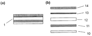
도 1은 코드 영역(2) 및 산란 영역(3)을 포함하는 본 발명에 의한 보안 소자(1)의 바람직한 실시태양을 개략적으로 도시한다. 코드 영역(2)은 밝은 배경에서 어두운 색조로 인쇄된 바아 코드의 형태의 광학 코드를 포함한다. 산란 영역(3)은 실선으로 이루어진 프레임에 의하여 나타난다. 산란 영역(3) 및 코드 영역(2)은 서로에 대하여 공간적으로 분리되어 있다. 도 1에서의 본 발명에 의한 보안 소자는 둥근 형태로 구체화되어 있다. 이 예에서의 직경은 40 내지 60 ㎜이다. 도시된 소자(산란 영역, 코드 영역, 프레이밍) 이외에, 특히 텍스트, 화상 및 문자로 인쇄된 추가의 소자도 가능하다.
도 2는 본 발명에 의한 보안 소자의 (a) 단면, (b) 확대 단면의 바람직한 실시태양의 층 구조를 개략적으로 도시한다. 아래로부터의 층 순서는 접착 보호층(10), 접착층(11), 섬유상 소재를 포함하는 층(12), 인쇄층(13) 및 보호층(14)이다. 이러한 경우에서, 섬유상 소재층(12)은 분리 시도의 경우에서의 소정의 파손 위치(분리층)를 제공하는 기능뿐 아니라, 랜덤 분포 및/또는 배향된 산란 중심을 제공하는 기능 및 인쇄 잉크(인쇄층)를 수용하는 기능을 수행한다.
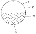
도 3은 본 발명에 의한 보안 소자(1)에서의 스탬핑 부분의 도입을 개략적으로 도시한다. 본 실시태양에서는 3 가지 유형의 스탬핑 부분인 보안 소자의 엣지 영역에서의 방사상 보안 스탬핑 부분(20), 보안 소자상에서의 파동형 보안 스탬핑 부분(21) 및 보안 소자의 엣지 영역내의 외부 윤곽 스탬핑 부분(22)이 존재한다.
도 4는 3가지 예에 기초하여 본 발명에 의한 보안 소자의 층이 스탬핑 부분에 의하여 실시될 수 있는 것을 개략적으로 도시한다. 스탬핑 부분의 추가의 가능성도 또한 가능하다. 도 2로부터의 층 순서가 예를 들면 층 순서로서 작용한다. 스탬핑 부분(31)은 보호층, 인쇄층 및 섬유상 소재층을 통하여 기능한다. 스탬핑 부분은 또한 접착층을 통하여 작동하는 것도 가능하다. 스탬핑 부분(31)의 방법에서의 스탬핑 부분은 보안 소자가 물체로부터 전체로서 분리될 수 없는 효과를 갖는다. 분리 시도는 스탬핑 라인을 따라 보안 소자의 분할을 초래한다. 도시한 스탬핑 부분(31)은 보호층을 통하여 기능하는 단점을 갖는다. 그 결과, 예를 들면 수분이 그 아래 추가로 존재하는 층으로 침투되어 손상을 초래할 수 있다. 스탬핑 부분(32)은 인쇄층, 섬유상 소재층 및 접착층을 통하여 기능한다. 여기서 보호층은 영향을 받지 않으며, 그리하여 이의 기능을 완전 수행할 수 있다. 게다가, 분리 시도의 경우, 보호층은 찢어지게 되며(비가역적 손상), 이는 식별 가능하며, 분리 시도를 나타낸다. 스탬핑 부분(33)은 섬유상 소재층을 통하여서만 부분적으로 기능한다. 분리 시도는 섬유상 소재층 및 보호층에서의 비가역적 손상으로부터 식별 가능하다.
도 5는 실시예 1로부터의 본 발명에 의한 보안 소자의 바람직한 실시태양의 층 구조를 개략적으로 도시한다(세부 사항은 실시예 1 참조).
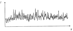
도 6은 실시예 2에 기재한 방법에 의하여 측정한, 실시예 1로부터의 본 발명에 의한 보안 소자의 바람직한 실시태양의 특징적인 산란 신호를 도시한다.1 schematically shows a preferred embodiment of a
Figure 2 schematically shows the layer structure of a preferred embodiment of (a) cross section, (b) enlarged cross section of a security element according to the invention. The layer order from below is the adhesive
3 schematically shows the introduction of a stamping part in a
4 schematically shows that a layer of the security element according to the invention can be implemented by a stamping part based on three examples. Further possibilities of stamping parts are also possible. The layer order from FIG. 2 acts as a layer order, for example. The stamping
5 schematically shows the layer structure of a preferred embodiment of a security element according to the invention from Example 1 (see Example 1 for details).
FIG. 6 shows characteristic scattering signals of a preferred embodiment of the security element according to the invention from Example 1, measured by the method described in Example 2. FIG.
실시예 1 - 본 발명에 의한 보안 소자의 제조 및 구조Example 1 Fabrication and Structure of Security Device According to the Present Invention
본 발명에 의한 보안 소자의 바람직한 실시태양의 구조는 확대 도면 형태로 도 5(b)에 개략적으로 도시한다.The structure of a preferred embodiment of the security element according to the invention is shown schematically in FIG. 5 (b) in the form of an enlarged view.
하부 영역(41)은 3M으로부터의 특수 종이 7110(3M 7110 리토 페이터, 백색)으로 형성된다. 이와 같은 특수 종이는 접착 보호층, 접착층 및 섬유상 소재층의 층 순서를 이미 포함하는 복합재이다. 접착층은 제조업자의 정보에 의한 기재(예, 폴리에틸렌 또는 폴리프로필렌)에 대한 접착력이 섬유상 소재층의 강도보다 더 큰 강하게 접착되는 아크릴레이트 접착제이다. 그리하여, 섬유상 소재층은 분리 시도가 있는 경우 찢어지는 분리층으로 작용한다.
특수 종이 7110은 -40℃ 내지 175℃ 범위내에서 온도에 대한 저항성을 갖는다. 매트(matt) 표면은 인쇄 가능하며, 광학 코드(및 적절할 경우 추가의 인쇄 화상)로 인쇄하기 위한 표면을 제공한다. 동시에, 특수 종이의 각각의 영역에 대하여 고유한 특수 종이의 섬유 구조는 300 ㎚ 내지 1,000 ㎚ 범위내의 1 이상의 파장을 갖는 전자기 방사로 특수 종이를 방사하면 보안 소자(또는 보안 소자에 연결된 물체)를 인증할 수 있도록 하는 특징적인 산란 신호를 생성하도록 랜덤 배향 및/또는 분포된 산란 중심을 제공한다.Specialty paper 7110 is temperature resistant in the range of -40 ° C to 175 ° C. Matt surfaces are printable and provide a surface for printing with optical codes (and additional printed images, where appropriate). At the same time, the fiber structure of the special paper, which is unique for each area of the special paper, authenticates the security element (or object connected to the security element) by radiating the special paper with electromagnetic radiation having one or more wavelengths in the range of 300 nm to 1,000 nm. Random scattering and / or distributed scattering centers are provided to produce a characteristic scattering signal that allows
프라이머(42)는 인쇄 잉크의 더 우수한 접착에 기여한다. 본 발명에서는 휴렛 패커드로부터의 제품 Indigo Topaz 10 Solution MPS-2056-42를 프라이머로서 사용하였다. 프라이머를 공지의 인쇄 기법(예를 들면, 디지탈 인쇄)에 의하여 전면에 걸쳐 특수 종이에 적용하였다. 색상 변경층(43) 및 인쇄층(44)을 공지의 기법(예를 들면 디지탈 인쇄)에 의하여 프라이머(42)에 적용한다. 색상 변경층(43)은 약 120℃의 온도를 초과하는 경우 투명에서 흑색으로 색상이 비가역적으로 변경되는 온도-민감성 변화 잉크를 포함한다. 사용한 변화 잉크는 제조업자 플렉소 앤 그라비아 잉크로부터 상표명 ThermaFlag W/B로 시판된다. 변화 잉크는 (도 5에 도시한 것과는 반대로) 코드 영역에만 인쇄되는 것이 바람직하다. 광학 코드는 공지의 인쇄 기법(예를 들면 디지탈 인쇄)에 의하여 변화 잉크에 인쇄된다. 복합재의 마지막은 보호층(45)에 의하여 형성된다. 본 발명에서 UPM 라플라택으로부터의 적층재 PET Overlam RP35를 공지의 적층 방법에 의하여 보호 필름으로서 적용하였다.The
도 5(a)는 보안 소자(40)에서의 스탬핑 부분의 경로를 도시한다. 3 가지 유형의 스탬핑 부분은 도 3에 의하면 방사상 보안 스탬핑 부분(20), 파동형 보안 스탬핑 부분(21) 및 외부 윤곽 스탬핑 부분(22)으로 존재한다. 방사상 보안 스탬핑 부분(20) 및 외부 윤곽 스탬핑 부분(22)은 도 5(a)에서 개략적으로 도시한 바와 같이 모든 층을 통하여 기능하며, 접착 보호층(영역(41)의 하부 부분)은 스탬핑 부분으로부터 제외하였다. 파동형 보안 스탬핑 부분(21)은 특수 종이를 통하여 기능하며, 여기서는 마찬가지로 접착 보호층을 스탬핑 부분으로부터 제외하였다.5 (a) shows the path of the stamping portion in the
실시예 2 - 본 발명에 의한 보안 소자의 특징적인 산란 신호의 측정Example 2 Measurement of Characteristic Scattering Signals of a Security Device According to the Present Invention
실시예 1로부터의 본 발명에 의한 보안 소자의 특징적인 산란 신호는 WO2005/088533 A1에 기재된 방법에 의하여 측정하였다. 본 발명에 의한 보안 소자는 도 1에 의한 코드 영역 및 산란 영역 및 도 3에 의한 스탬핑 부분의 형태, 크기 및 공간 분포를 가지며, 여기서 산란 영역은 스탬핑 부분에 의하여 영향을 받지 않는다.Characteristic scattering signals of the security device according to the invention from Example 1 were measured by the method described in WO2005 / 088533 A1. The security element according to the present invention has the shape, size and spatial distribution of the code region and the scattering region according to FIG. 1 and the stamping portion according to FIG. 3, where the scattering region is not affected by the stamping portion.
산란 신호는 검출기로서 FP-65/5 유형의 Flexpoint® 레이저(파장 650 ㎚, 최대 전력 5 ㎽) 및 STM으로부터의 FT-30 유형의 Si NPN 광트랜지스터와 함께 WO2005/088533 A1로부터의 도 1에 의한 장치를 사용하여 측정하였다.Scattering signal is shown by FIG. 1 from WO2005 / 088533 A1 with a FP-65 / 5 type Flexpoint ® laser (wavelength 650 nm, maximum power 5 kW) and FT-30 type Si NPN phototransistor from STM. Measurement was made using the apparatus.
보안 소자상의 레이저의 비임 프로파일은 선형이며, 길이는 2 ㎜이고, 폭은 20 ㎛이다. 레이저 및 검출기의 정밀한 배치는 산란 영역의 1.5 ㎝의 영역에 걸친 비임 프로파일의 긴 부분에 대하여 횡방향으로 일정한 속도(약 2 ㎝/초)로 안내된다.The beam profile of the laser on the security element is linear, 2 mm long and 20 μm wide. Precise placement of the laser and detector is guided at a constant speed (about 2 cm / sec) in the transverse direction with respect to the long portion of the beam profile over an area of 1.5 cm of the scattering area.
도 6은 임의의 단위로 이동하는 거리 x의 함수로서 검출기(WO2005/088533 A1의 도 1로부터의 검출기 16b)로 검출된 산란 방사의 강도 I를 도시한다. 산란 신호는 개개의 본 발명에 의한 보안 소자 각각에 대하여 고유한 것이므로, 이를 인증에 사용할 수 있다.FIG. 6 shows the intensity I of scattered radiation detected by the detector (detector 16b from FIG. 1 of WO2005 / 088533 A1) as a function of distance x traveling in any unit. The scattering signal is unique for each of the individual security elements of the present invention and can therefore be used for authentication.
1 라벨형 보안 소자
2 바아 코드 형태의 광학 코드를 포함하는 코드 영역
3 실선으로 프레임 처리하여 시각적으로 마킹된 산란 영역
10 접착 보호층
11 접착층
12 섬유상 소재 함유 층
13 인쇄층
14 보호층
20 방사상 보안 스탬핑 부분
21 파동형 보안 스탬핑 부분
22 외부 윤곽 스탬핑 부분
31 보호층, 인쇄층 및 섬유상 소재 함유 층을 통한 스탬핑 부분
32 인쇄층, 섬유상 소재 함유 층 및 접착층을 통한 스탬핑 부분
33 부분적으로 섬유상 소재 함유 층을 통한 스탬핑 부분
41 3M으로부터의 특수 종이 7110
42 휴렛 패커드로부터의 Primer Indigo Topaz 10 Solution MPS-2056-42
43 플렉소 앤 그라비아 잉크로부터 변경 잉크 ThermaFlag W/B
44 인쇄 잉크
45 UPM 라플라택으로부터의 보호층 PET Overlam RP35.1 Labeled Security Devices
Code area containing optical code in the form of a 2 bar code
3 Scattered areas visually marked by framing with solid lines
10 Adhesive Protective Layer
11 adhesive layer
12 fibrous material-containing layers
13 printed layers
14 protective layer
20 radial security stamping parts
21 Wave Security Stamping Part
22 outer contour stamping parts
31 Stamping part through protective layer, printed layer and fibrous material-containing layer
32 Stamping part through printed layer, fibrous material containing layer and adhesive layer
33 Stamping part partially through fibrous material-containing layer
41 Specialty paper from 3M 7110
Change Ink ThermaFlag W / B from 43 Flexo & Gravure Ink
44 printing inks
45 Protective layer PET Overlam RP35 from UPM Laplac.
Claims (9)
(B) 보안 소자의 특징적인 산란 신호를 측정하는 단계,
(C) 특징적인 산란 신호를 기준 데이타 기록과 비교하는 단계,
(D) 상기 단계 (C)에서의 비교의 결과에 따르는 방식으로 물체의 진위성에 대한 통지를 출력하는 단계를 적어도 포함하는, 제1항 내지 제6항 중 어느 한 항에 따른 보안 소자에 기초한 물체의 식별 및 인증 방법.
(A) reading the optical code on the security element and measuring the reference data record,
(B) measuring a scattering signal characteristic of the security element,
(C) comparing the characteristic scattering signal with a reference data record,
(D) an object based on the security element according to any one of claims 1 to 6, at least including the step of outputting a notification of the authenticity of the object in a manner according to the result of the comparison in step (C). Identification and authentication methods.
Applications Claiming Priority (6)
| Application Number | Priority Date | Filing Date | Title |
|---|---|---|---|
| DE102008007731.3 | 2008-02-05 | ||
| DE102008007731A DE102008007731B4 (en) | 2008-02-05 | 2008-02-05 | Method and device for identifying and authenticating objects |
| DE102008016803.3 | 2008-04-02 | ||
| DE102008016803A DE102008016803A1 (en) | 2008-04-02 | 2008-04-02 | Object e.g. person, identifying/authenticating method, involves extracting characteristic feature, and comparing feature with object's characteristic feature that is stored in data base and detected at specific time point |
| DE200810053798 DE102008053798A1 (en) | 2008-10-29 | 2008-10-29 | Object i.e. commodity, identifying and/or authenticating method, involves using electromagnetic radiation reflected by code zone to identify object and using electromagnetic radiation reflected by dispersion zone to authenticate object |
| DE102008053798.5 | 2008-10-29 |
Publications (1)
| Publication Number | Publication Date |
|---|---|
| KR20100117597A true KR20100117597A (en) | 2010-11-03 |
Family
ID=40886117
Family Applications (1)
| Application Number | Title | Priority Date | Filing Date |
|---|---|---|---|
| KR1020107017453A KR20100117597A (en) | 2008-02-05 | 2009-01-24 | Security element |
Country Status (8)
| Country | Link |
|---|---|
| US (1) | US20110018253A1 (en) |
| EP (1) | EP2259930A2 (en) |
| JP (1) | JP2011514548A (en) |
| KR (1) | KR20100117597A (en) |
| CN (1) | CN101939173B (en) |
| BR (1) | BRPI0907479A2 (en) |
| MX (1) | MX2010008480A (en) |
| WO (1) | WO2009097980A2 (en) |
Families Citing this family (12)
| Publication number | Priority date | Publication date | Assignee | Title |
|---|---|---|---|---|
| DE102009052538A1 (en) * | 2009-11-11 | 2011-05-12 | Giesecke & Devrient Gmbh | Producing a provided with colored microwells security element |
| DE102010015014A1 (en) | 2010-04-14 | 2011-10-20 | Bayer Technology Services Gmbh | Optical scanner |
| DE102010020810A1 (en) | 2010-05-18 | 2011-11-24 | Bayer Technology Services Gmbh | Identification of objects |
| DE102010021380A1 (en) | 2010-05-25 | 2011-12-01 | Bayer Technology Services Gmbh | Identification of objects |
| US10832015B2 (en) | 2011-03-10 | 2020-11-10 | Joseph A. Hattrup Trust Dated July 16, 1996, As Amended | On-the-fly marking systems for consumer packaged goods |
| US9436770B2 (en) | 2011-03-10 | 2016-09-06 | Fastechnology Group, LLC | Database systems and methods for consumer packaged goods |
| US20150231896A1 (en) * | 2011-03-10 | 2015-08-20 | Fastechnology Group, LLC | Inverted codes on transparent packaging exterior |
| JP2013190478A (en) * | 2012-03-12 | 2013-09-26 | Toppan Printing Co Ltd | Forgery prevention medium, adhesive label, transfer foil, and labeled article |
| EP2878453A1 (en) * | 2013-11-28 | 2015-06-03 | Authentic Vision GmbH | Object markings for optical authentication and method for their production |
| EP3154015A1 (en) * | 2015-10-09 | 2017-04-12 | Authentic Vision GmbH | Authentication method for article identifiers |
| CN106585164B (en) * | 2016-11-30 | 2018-01-19 | 东莞市天眼网络科技有限公司 | A kind of method of false-proof texture and anti-counterfeit printed of generating |
| DE102021114841A1 (en) | 2021-06-09 | 2022-12-15 | Schreiner Group Gmbh & Co. Kg | Film composite with protection against manipulation |
Family Cites Families (20)
| Publication number | Priority date | Publication date | Assignee | Title |
|---|---|---|---|---|
| NL7406230A (en) * | 1973-05-11 | 1974-11-13 | ||
| NL9001368A (en) * | 1990-06-15 | 1992-01-02 | Tel Developments B V | SECURITY OF OBJECTS OR DOCUMENTS. |
| GB9116097D0 (en) * | 1991-07-25 | 1991-09-11 | Ordonez Gabriel | Security price or barcode label |
| JPH08156473A (en) * | 1994-12-06 | 1996-06-18 | Dainippon Printing Co Ltd | Note or the like and forgery preventing method |
| JPH10241000A (en) * | 1997-02-26 | 1998-09-11 | Ricoh Co Ltd | Method and device for special document discrimination and mechanically readable recording medium recording program for execution of the method in computer |
| WO1998057299A1 (en) * | 1997-06-11 | 1998-12-17 | Nova-Technik Entwicklung Von Und Handel Mit Medizinischen Geräten Gmbh | Document with an authentication feature |
| FR2765014B1 (en) * | 1997-06-24 | 2000-02-11 | Rene Boulnois | PAPER DOCUMENT AUTHENTICATION PROCESS, PAPER SECURITY DOCUMENT, AND DEVICE FOR CHECKING THE AUTHENTICITY OF PAPER DOCUMENTS |
| US6904525B1 (en) * | 1997-07-01 | 2005-06-07 | Pitney Bowes Inc. | Method for preventing counterfeiting of articles of manufacture |
| DE19807232C1 (en) * | 1998-02-20 | 1999-07-08 | Schreiner Etiketten | Multi-layer label |
| JP2000293108A (en) * | 1999-04-02 | 2000-10-20 | Kuramoto Sangyo:Kk | Forgery preventing label |
| AU2087200A (en) * | 1999-12-08 | 2001-06-18 | Valentin Alexandrovich Mischenko | Method and system for authentication of articles |
| US6550685B1 (en) * | 2000-11-14 | 2003-04-22 | Hewlett-Packard Development Company Lp | Methods and apparatus utilizing visually distinctive barcodes |
| JP4030830B2 (en) * | 2002-08-13 | 2008-01-09 | 日本電気株式会社 | Striped image examination apparatus and striped image examination method |
| CN2715245Y (en) * | 2003-09-22 | 2005-08-03 | 兆日科技(深圳)有限公司 | Texture password label |
| RU2385492C2 (en) * | 2004-03-12 | 2010-03-27 | Инджениа Текнолоджи Лимитед | Methods, articles and devices for verification of authenticity |
| MXPA06010401A (en) * | 2004-03-12 | 2007-01-19 | Ingenia Technology Ltd | Methods and apparatuses for creating authenticatable printed articles and subsequently verifying them. |
| JP2006082481A (en) * | 2004-09-17 | 2006-03-30 | Bridgestone Sports Co Ltd | Method for printing on golf ball box or golf ball packaging material, and golf ball box or golf ball packaging material |
| JP2006235257A (en) * | 2005-02-25 | 2006-09-07 | Nichiei Kako Kk | Label for security |
| US7624928B2 (en) * | 2005-11-18 | 2009-12-01 | Fuji Xerox Co., Ltd. | Method and apparatus for making tags, tag, and system for managing articles |
| US20080129037A1 (en) * | 2006-12-01 | 2008-06-05 | Prime Technology Llc | Tagging items with a security feature |
-
2009
- 2009-01-24 BR BRPI0907479A patent/BRPI0907479A2/en not_active IP Right Cessation
- 2009-01-24 MX MX2010008480A patent/MX2010008480A/en unknown
- 2009-01-24 WO PCT/EP2009/000451 patent/WO2009097980A2/en active Application Filing
- 2009-01-24 CN CN2009801043143A patent/CN101939173B/en not_active Expired - Fee Related
- 2009-01-24 JP JP2010545383A patent/JP2011514548A/en not_active Ceased
- 2009-01-24 KR KR1020107017453A patent/KR20100117597A/en not_active Application Discontinuation
- 2009-01-24 US US12/865,578 patent/US20110018253A1/en not_active Abandoned
- 2009-01-24 EP EP09707754A patent/EP2259930A2/en not_active Withdrawn
Also Published As
| Publication number | Publication date |
|---|---|
| US20110018253A1 (en) | 2011-01-27 |
| JP2011514548A (en) | 2011-05-06 |
| BRPI0907479A2 (en) | 2019-02-26 |
| EP2259930A2 (en) | 2010-12-15 |
| WO2009097980A2 (en) | 2009-08-13 |
| MX2010008480A (en) | 2011-02-23 |
| CN101939173A (en) | 2011-01-05 |
| CN101939173B (en) | 2012-06-20 |
| WO2009097980A3 (en) | 2009-12-03 |
Similar Documents
| Publication | Publication Date | Title |
|---|---|---|
| KR20100117597A (en) | Security element | |
| EP2002385B1 (en) | Method of reading at least one bar code and system for reading a bar code | |
| US20060244253A1 (en) | Texture coding label | |
| JP2017117454A (en) | Optical code, creation method of optical code, authenticity determination method of optical code, optical code reading device, and reading support device | |
| US20090074231A1 (en) | Secure Article, Notably a Security and/or Valuable Document | |
| JP2008542916A (en) | Method and apparatus for authenticating products | |
| KR101586885B1 (en) | Security document with holographic foil and printed machine-readable markings | |
| JP2010507847A (en) | Apparatus, method and process for stochastic marking and tracking of printed products | |
| WO2012023363A1 (en) | Method for authenticity assessment easily performed by ordinary people using printed minute identification mark | |
| RU2493968C2 (en) | Security element | |
| KR20200044808A (en) | Laminate, identification certificate, and verification method of identification certificate | |
| JP2008080610A (en) | Mechanically readable information printed material | |
| US20120162666A1 (en) | Position marking for identifying a surface region and method for identifying/authenticating on the basis of the marked surface region | |
| JP6482556B2 (en) | Method and apparatus for verifying security elements of a security document | |
| JP6260282B2 (en) | Anti-counterfeit medium and authenticity determination device | |
| JP4264776B2 (en) | Safety protection sheet, authenticity determination method thereof, and authenticity determination device thereof | |
| KR20190111077A (en) | Security features for authentication and harvesting prevention using machine detectable indicators | |
| JP2007136838A (en) | Printed matter for certification and certifying method of the same | |
| KR102011604B1 (en) | Method and Apparatus for Providing Authenticity Determination | |
| JP2000029391A (en) | Label for discriminating authenticity, rom stuck with the same and authenticity discrimination method of rom | |
| JPH01278397A (en) | Card and method for discriminating kind thereof | |
| KR101906480B1 (en) | Security sheet for authenticity determination and method for determinating authenticity using the same | |
| JP2015223766A (en) | Password information printed matter and determination method thereof | |
| DE102008053798A1 (en) | Object i.e. commodity, identifying and/or authenticating method, involves using electromagnetic radiation reflected by code zone to identify object and using electromagnetic radiation reflected by dispersion zone to authenticate object | |
| JP2020194069A (en) | Authentication medium and manufacturing method thereof |
Legal Events
| Date | Code | Title | Description |
|---|---|---|---|
| N231 | Notification of change of applicant | ||
| WITN | Application deemed withdrawn, e.g. because no request for examination was filed or no examination fee was paid |