JP2011514548A - Security element - Google Patents
Security element Download PDFInfo
- Publication number
- JP2011514548A JP2011514548A JP2010545383A JP2010545383A JP2011514548A JP 2011514548 A JP2011514548 A JP 2011514548A JP 2010545383 A JP2010545383 A JP 2010545383A JP 2010545383 A JP2010545383 A JP 2010545383A JP 2011514548 A JP2011514548 A JP 2011514548A
- Authority
- JP
- Japan
- Prior art keywords
- security element
- layer
- element according
- security
- characteristic
- Prior art date
- Legal status (The legal status is an assumption and is not a legal conclusion. Google has not performed a legal analysis and makes no representation as to the accuracy of the status listed.)
- Ceased
Links
Images


Classifications
-
- B—PERFORMING OPERATIONS; TRANSPORTING
- B42—BOOKBINDING; ALBUMS; FILES; SPECIAL PRINTED MATTER
- B42D—BOOKS; BOOK COVERS; LOOSE LEAVES; PRINTED MATTER CHARACTERISED BY IDENTIFICATION OR SECURITY FEATURES; PRINTED MATTER OF SPECIAL FORMAT OR STYLE NOT OTHERWISE PROVIDED FOR; DEVICES FOR USE THEREWITH AND NOT OTHERWISE PROVIDED FOR; MOVABLE-STRIP WRITING OR READING APPARATUS
- B42D25/00—Information-bearing cards or sheet-like structures characterised by identification or security features; Manufacture thereof
- B42D25/40—Manufacture
- B42D25/45—Associating two or more layers
- B42D25/465—Associating two or more layers using chemicals or adhesives
- B42D25/47—Associating two or more layers using chemicals or adhesives using adhesives
-
- B—PERFORMING OPERATIONS; TRANSPORTING
- B42—BOOKBINDING; ALBUMS; FILES; SPECIAL PRINTED MATTER
- B42D—BOOKS; BOOK COVERS; LOOSE LEAVES; PRINTED MATTER CHARACTERISED BY IDENTIFICATION OR SECURITY FEATURES; PRINTED MATTER OF SPECIAL FORMAT OR STYLE NOT OTHERWISE PROVIDED FOR; DEVICES FOR USE THEREWITH AND NOT OTHERWISE PROVIDED FOR; MOVABLE-STRIP WRITING OR READING APPARATUS
- B42D25/00—Information-bearing cards or sheet-like structures characterised by identification or security features; Manufacture thereof
- B42D25/20—Information-bearing cards or sheet-like structures characterised by identification or security features; Manufacture thereof characterised by a particular use or purpose
- B42D25/29—Securities; Bank notes
-
- B—PERFORMING OPERATIONS; TRANSPORTING
- B42—BOOKBINDING; ALBUMS; FILES; SPECIAL PRINTED MATTER
- B42D—BOOKS; BOOK COVERS; LOOSE LEAVES; PRINTED MATTER CHARACTERISED BY IDENTIFICATION OR SECURITY FEATURES; PRINTED MATTER OF SPECIAL FORMAT OR STYLE NOT OTHERWISE PROVIDED FOR; DEVICES FOR USE THEREWITH AND NOT OTHERWISE PROVIDED FOR; MOVABLE-STRIP WRITING OR READING APPARATUS
- B42D25/00—Information-bearing cards or sheet-like structures characterised by identification or security features; Manufacture thereof
Abstract
本発明は、目的物を識別及び認証するためのセキュリティエレメントに関する。目的物に対して自動接着式の形式で繋げられる。目的物からセキュリティエレメントを非破壊で分離することを実効的に回避するという特徴を有する。セキュリティエレメントは認識のための光学コードを有する。更に、認証が可能であるランダムな製法支配の特性を設けられる。電磁波放射で照射すると、セキュリティエレメントの散乱領域は、特徴的な散乱信号を発生する。更に本発明は、目的物を識別及び認証し又偽造に対して保護するセキュリティエレメントの利用に関し、並びに、本発明に係るセキュリティエレメントに基づいて目的物を識別し認証する方法に関する。The present invention relates to a security element for identifying and authenticating objects. Connected to the target in an automatic adhesive format. It has the feature of effectively avoiding non-destructive separation of the security element from the object. The security element has an optical code for recognition. Furthermore, a random process-dominated characteristic that can be authenticated is provided. When irradiated with electromagnetic radiation, the scattering region of the security element generates a characteristic scattering signal. The invention further relates to the use of security elements for identifying and authenticating objects and protecting against counterfeiting, and to a method for identifying and authenticating objects based on the security elements according to the invention.
Description
本発明は、セキュリティエレメント、目的物の識別と認証のための及び偽造に対する保護のためのセキュリティエレメントの利用、及び、発明に係るセキュリティエレメントに基づいて目的物の識別と認証のための方法に関する。 The present invention relates to a security element, the use of a security element for object identification and authentication and for protection against counterfeiting, and a method for object identification and authentication based on the security element according to the invention.
光学的方法により対象物を自動認識することが、先行技術により知られている。例えば、商品及び/又はパッケージに付され、価格などを決めるべく商品の機械識別を可能にするバーコードは、万人に知られている。 It is known from the prior art to automatically recognize objects by optical methods. For example, a barcode that is attached to a product and / or package and enables machine identification of the product to determine a price or the like is known to everyone.
バーコードの一つの公知の典型は、国際標準ISO/IEC15420に規定されるEAN8コードである。それは、異なる幅のバーとギャップの形態で8つの数字のシーケンスをコード化する。通常、バーは、黒の印刷インクで白のキャリア上に、例えば、識別される目的物のパッケージの上に、若しくは目的物自体上に、印刷される。 One known representative of barcodes is the EAN8 code defined in the international standard ISO / IEC15420. It encodes a sequence of 8 numbers in the form of different width bars and gaps. Typically, the bars are printed with black printing ink on a white carrier, for example on the package of the object to be identified, or on the object itself.
上記記載のEAN8コードに加えて、数字だけでなく文字、特殊文字、制御文字などもコード化する更なる多数のバーコードが、存在する。更には、信号伝送のエラーの検出や部分的な訂正も可能にする、エラー検出及びエラー訂正キャラクタを含むコードもある。更に発展したバーコードは2Dコードであり、その2Dコードでは情報は1次元だけでなく2次元で光学的にコード化される。いわゆるマトリクスコードは、2Dコードのサブグループを形成する。一つの公知の典型は、例えば、国際標準ISO/IEC16022に規定されるデータマトリクスコードである。 In addition to the EAN8 code described above, there are a number of other barcodes that encode not only numbers but also characters, special characters, control characters, and the like. In addition, some codes include error detection and error correction characters that allow detection and partial correction of signal transmission errors. A further developed barcode is a 2D code, in which information is optically encoded in two dimensions as well as in one dimension. So-called matrix codes form a subgroup of 2D codes. One known typical is, for example, a data matrix code defined in the international standard ISO / IEC16022.
上述のバーコードのような機械読み取り可能の光学コード、2Dコード、及びマトリクスコードだけでなく、OCR−Text(テキスト)(OCR=光学文字認識)若しくは類似の光学式機械読み取り可能コードは、以下では、光学コードの用語のものに含まれる。 Machine-readable optical codes such as the barcodes described above, 2D codes, and matrix codes, as well as OCR-Text (OCR = optical character recognition) or similar optical machine-readable codes are described below. , Included in the term optical code.
光学コードは、簡素に且つ非常にコスト効率よく(印刷により)形成可能であり、迅速且つ堅実に検出される。光学コードは、目的物の識別に理想的に適合するものである。特に、光学コードは目的物の追跡に適する(トラック及びトレース)。この場合、物流チェーンのあらゆるステーションにて目的物が識別され得るように、目的物には、例えば、固有の番号が付され、これにより、物流チェーンの一つのステーションから別のステーションへの目的物の移動を追跡することが可能である。 The optical code can be formed simply and very cost-effectively (by printing) and is detected quickly and consistently. The optical code is ideally suited for object identification. In particular, optical codes are suitable for tracking objects (tracks and traces). In this case, the object is given a unique number, for example, so that the object can be identified at every station of the logistics chain, so that an object from one station of the logistics chain to another station can be identified. It is possible to track movements.
しかしながら、光学コードは簡単に複写し再生することができるので、光学コードは偽造に対して防御をすることができない。 However, since the optical code can be easily copied and reproduced, the optical code cannot protect against counterfeiting.
偽造に対するセキュリティのために、識別カード、紙幣、商品などには、今日、特別な知識及び/又は高度の技術的複雑性によってのみ模倣され得るエレメントが設けられる。そのようなエレメントを本明細書ではセキュリティエレメントと称する。セキュリティエレメントは、保護される目的物に不可分に繋がれるのが好ましい。セキュリティエレメントが悪用され得ないように、目的物からセキュリティエレメントを分離しようと試みるとセキュリティエレメントが壊れてしまうようになることが好ましい。 For security against counterfeiting, identification cards, banknotes, merchandise, etc. are today provided with elements that can only be imitated by special knowledge and / or high technical complexity. Such an element is referred to herein as a security element. The security element is preferably inextricably linked to the object to be protected. In order to prevent the security element from being abused, it is preferred that the security element breaks when attempting to separate the security element from the object.
目的物の真偽は、一つ若しくはそれ以上のセキュリティエレメントの存在に基づいて、チェックされ得る。目的物の真偽をチェックする方法を本明細書では認証と称する。 The authenticity of the object can be checked based on the presence of one or more security elements. The method for checking the authenticity of the object is referred to herein as authentication.
例えば、ウオータマーク、特殊インク、ギロシェパターン、マイクロテキスト、及びホログラムなどの、光学セキュリティエレメントは、全世界的に確立された技術である。特に、文書保護に適切であり又それに限定されない光学セキュリティエレメントの概略は、次の本、即ち非特許文献1に記載されている。
For example, optical security elements such as watermarks, special inks, guilloche patterns, microtext, and holograms are globally established technologies. In particular, an outline of an optical security element that is suitable for document protection and not limited thereto is described in the following book, namely Non-Patent
特許文献1は、目的物の特徴及び構造に基づいて目的物が識別され認証され得る方法を記載する。この場合、例えば、目的物に繋がれるセキュリティエレメントなどの追加の手段無しで、方法が動作する。この方法では、レーザビームは目的物の表面上で焦点を合わされ、表面中を移動し(スキャニング)、表面の様々な位置で様々な角度で様々な程度に散乱されるビームは、光検出器により検出される。検出される散乱放射は目的物の作成の間のランダムな発生に起因するものであるから、様々な異なる部材に関して特徴的であり、非常な困難によってしか模倣され得ない。例として、紙状の目的物は、作成される個々の目的物に対して一意的である製法支配のファイバ構造を有する。個別の目的物に関する散乱データは、後の時点で目的物を認証できるように、データベース内に格納される。この目的のために、目的物が再び計測され、散乱データが格納された参照データと比較される。
特許文献1の方法で利用される目的物のランダムな特徴は、偽造に対して非常に高度な保護をもたらす。しかしながら、この方法の不都合なことは、検出される全ての目的物の散乱データのために、広範なデータベースを作成することが必要であることである。一方で、データベースは、多数の目的物の散乱データの高データボリュームを格納できるように、高格納容量を有さなければならない。他方で、正確なデータを見つけるために、検出される散乱データは、認証のためにデータベース内の全ての参照データと比較されなければならないので、データベース内のデータへのアクセス時間は、迅速でなければならない。
The random characteristics of the object used in the method of
更に、どの目的物も特許文献1に係る方法にアクセス可能な表面を有している、というわけではない。 Furthermore, not every object has a surface accessible to the method according to US Pat.
このように、先行技術は、目的物の識別及び認証のための種々の方法及び装置を提供すると要約できる。しかしながら、光学コードにより識別する方法及び装置は、識別のために利用される特徴を簡単に偽造できるため、偽造に対する保護として適切ではなく更にもの認証のためには適切ではない。反対に、特許文献1の認証の方法は偽造に対して高い保護を有するが、高容量のデータ、及び、ITバックエンドシステムから成る厳格な関連要件のために、識別及び目的物追跡(トラック及びトレース)には適切ではない。更に、方法は全ての目的物に対して利用され得るものではない。
Thus, the prior art can be summarized as providing various methods and apparatus for object identification and authentication. However, the method and apparatus for identifying by optical code can be easily counterfeited for the features used for identification, so it is not suitable for protection against forgery and not for authentication. On the contrary, the authentication method of
従って、公知の先行技術から進んで、取り組むべき問題は、光学コードの利点を、ランダム特性に基づく認証の利点と組み合わせることである。取り組むべき問題は、様々な目的物の多様性に対して利用可能であり、実装が容易であり、現存のITインフラストラクチャに基づき確立可能であり、偽造に対して高い保護を保証し、更にはコスト効率的である、目的物の識別及び認証のための解決策を提供することである。 Thus, proceeding from the known prior art, the problem to be addressed is to combine the advantages of optical codes with the advantages of authentication based on random properties. The issues to be addressed are available for a variety of different objects, are easy to implement, can be established based on existing IT infrastructure, ensure high protection against counterfeiting, and To provide a solution for object identification and authentication that is cost effective.
目的物に不可逆的に添付され、コード領域と散乱領域を含み、コード領域は光学コードに基づく目的物の認証のために用いられ、散乱領域はランダムに与えられた特性による特徴的な散乱放射に基づくもの認証のために用いられる、セキュリティエレメントにより、上記問題は解決可能であることが、驚いたことに見出された。 Attached irreversibly to the object, including a code area and a scattering area, the code area is used for authentication of the object based on the optical code, and the scattering area is a characteristic scattered radiation with randomly assigned characteristics. It has been surprisingly found that the above problem can be solved by a security element used for authentication based.
従って、本発明は、セキュリティエレメントを目的物に添付するための自動接着性ラベルの形態のセキュリティエレメントに関し、セキュリティエレメントを目的物から壊すこと無く分離することを防ぐ手段を含み、セキュリティエレメントはコード領域と視覚上際立つ散乱領域を含み、コード領域は光学コードを含み、散乱領域は、電磁波放射により照射されるとセキュリティエレメントの特徴を為す一意的な散乱信号を生じる、ランダムに分布され及び/又は方向付けされた散乱センタを有する。 Accordingly, the present invention relates to a security element in the form of a self-adhesive label for attaching a security element to an object, including means for preventing the security element from being separated from the object without breaking the security element And a visually distinct scattering area, the code area contains an optical code, and the scattering area is randomly distributed and / or directionally produced when illuminated by electromagnetic radiation, resulting in a unique scattered signal characterizing the security element With an attached scattering center.
識別とは、目的物を一義的に認識するのに役立つプロセスであると理解される。目的物が一義的に理解されると、目的物は一義的に割り当てられ得る。即ち、認識された目的物に対して一義的な割り当てを為すことが可能である。例として、商品の識別された品目は、価格や行き先が割り当てられ得る。識別は、目的物を特徴付けて他の目的物から区別する特性に基づいて達成される。 Identification is understood to be a process that helps to unambiguously recognize an object. Once the object is uniquely understood, the object can be uniquely assigned. That is, a unique assignment can be made to the recognized object. As an example, an identified item of merchandise may be assigned a price or destination. Identification is achieved based on characteristics that characterize the object and distinguish it from other objects.
認証とは、主張される識別をチェックするプロセスとして理解される。目的物、ドキュメント若しくはデータの認証は、後のものが真正であることを確認することである。即ち、変更も、複写も、模倣もされていないオリジナルが関連しているということである。 Authentication is understood as the process of checking the claimed identity. Authentication of the object, document or data is to confirm that the latter is authentic. That is, originals that are not changed, copied, or imitated are related.
識別と同様に、認証は、目的物を特徴付けて他の目的物から区別する特性に基づいて達成される。 Similar to identification, authentication is achieved based on characteristics that characterize the object and distinguish it from other objects.
目的物の識別のための特性、及び、目的物の認証のための特性は、本発明に係るセキュリティエレメントにより提供される。 The characteristics for identifying the object and the characteristics for authenticating the object are provided by the security element according to the present invention.
コード領域は、識別に必要な特性を含む。この目的のために、コード領域は、少なくとも一つの光学コード、例えば、バーコード、若しくは2Dコード、又は他の光学的に機械読み取り可能なコードを含む。光学コードは、識別番号をセキュリティエレメントに付してコード化するのが好ましい。識別番号に基づいて、セキュリティエレメントと、例えば、データベース内のエントリ、参照としての特徴的散乱信号を含むファイル、又は他の現実の若しくは仮想の目的物との間で、一意的な割り当てをすることが可能である。光学コードは、明るい背景に暗いインクでプリントされるのが好ましい。光学コードが暗い背景に明るいインクでプリントされる、逆の表現も想定され得る。 The code area includes characteristics necessary for identification. For this purpose, the code area comprises at least one optical code, for example a bar code or 2D code, or other optically machine-readable code. The optical code is preferably encoded with an identification number attached to the security element. Based on the identification number, make a unique assignment between the security element and, for example, an entry in the database, a file containing the characteristic scattered signal as a reference, or other real or virtual object Is possible. The optical code is preferably printed with dark ink on a light background. The reverse representation where the optical code is printed with bright ink on a dark background can also be envisaged.
コード領域のサイズは、利用される光学コードのサイズにより決定される。コード領域のサイズは通常、50mm2と1000mm2の間の範囲内に在る。 The size of the code area is determined by the size of the optical code used. The size of the code area is usually in the range between 50 mm 2 and 1000 mm 2 .
本発明に係るセキュリティエレメントが、一つ以上のコード領域及び/又は一つ以上の光学コードを含むことが想定される。 It is envisaged that the security element according to the present invention comprises one or more code areas and / or one or more optical codes.
本発明に係るセキュリティエレメントの散乱領域は、電磁波放射による照射で特徴的な散乱信号を生成することを特徴とする。散乱とは、光束の形態で散乱領域に衝突する電磁波ビームが様々な方向に反射されることを意味すると理解される。平行な光束が衝突して平面ミラーで反射し、この場合に所定の角度で平行ビームとして反射し戻されると、散乱領域の場合の衝突放射は、多様な散乱センタにより様々な方向に反射し戻される。 The scattering region of the security element according to the present invention is characterized in that a characteristic scattering signal is generated by irradiation with electromagnetic radiation. Scattering is understood to mean that an electromagnetic wave beam impinging on the scattering region in the form of a light beam is reflected in various directions. When collimated light beams collide and are reflected by a plane mirror and then reflected back as a parallel beam at a predetermined angle, the impinging radiation in the scattering region is reflected back in various directions by various scattering centers. It is.
この場合、本発明に係るセキュリティエレメントの散乱領域の散乱センタは、ランダムな分布及び/又は方向付けに左右される。ランダムな分布及び/又は方向付けとは、個別の散乱センタの位置、及び/又は個別の散乱センタの方向付けは、作成プロセスにより予測できるようには設定され得ない、ということを意味すると理解される。個別の散乱センタの位置及び/又は方向付けは、作成プロセスの間のランダムな変動に左右される。従って、個別の散乱センタの位置及び/又は方向付けは、単純なやり方では複製され得ない。本発明に係るセキュリティ特性によりもたらされる高度な保護はこの事実に基づくものである。非常に高度な複雑性をもってしか再構築され得ない。更に、ランダムな分布及び/又は方向付けは個別化に資するものである。個々のセキュリティエレメントは、電磁波放射による照射をすると一意的で特徴的な散乱信号で明示されるランダムな分布及び/又は方向付け、若しくは散乱センタによって一意的となる。 In this case, the scattering center of the scattering region of the security element according to the invention depends on a random distribution and / or orientation. Random distribution and / or orientation is understood to mean that the position of the individual scattering centers and / or the orientation of the individual scattering centers cannot be set as predictable by the production process. The The position and / or orientation of individual scattering centers depends on random variations during the creation process. Thus, the position and / or orientation of individual scattering centers cannot be replicated in a simple manner. The high degree of protection afforded by the security features according to the present invention is based on this fact. It can only be reconstructed with very high complexity. Furthermore, the random distribution and / or orientation contributes to individualization. Individual security elements are made unique by a random distribution and / or orientation, or a scattering center, which is manifested by a unique and characteristic scattering signal when illuminated by electromagnetic radiation.
本発明に係るセキュリティエレメントの散乱センタは、1平方マイクロメートルから0.001平方ミリメートルのサイズを有するのが好ましい。散乱センタは、例えば、顔料(例えば、二酸化チタン)やファイバ(例えば、セルロース)などにより形成されてもよい。 The scattering center of the security element according to the present invention preferably has a size of 1 square micrometer to 0.001 square millimeter. The scattering center may be formed by, for example, a pigment (for example, titanium dioxide) or a fiber (for example, cellulose).
本発明に係るセキュリティエレメントの散乱センタは、電磁波放射による照射で特徴的な散乱放射を発生する製法支配のファイバ構造を有する繊維性部材により、設けられることが好ましい。そのようなファイバ構造は、例えば、紙、ボール紙若しくは布地で、存在する。紙が繊維性部材として用いられることは好ましい。 The scattering center of the security element according to the present invention is preferably provided by a fibrous member having a manufacturing-dominated fiber structure that generates characteristic scattered radiation by irradiation with electromagnetic radiation. Such fiber structures exist, for example, in paper, cardboard or fabric. It is preferable that paper is used as the fibrous member.
300nmから1000nmの範囲内の少なくとも一つの波長を有する電磁波放射が、本発明に係るセキュリティエレメントの散乱領域により散乱されてもよい。 Electromagnetic radiation having at least one wavelength in the range of 300 nm to 1000 nm may be scattered by the scattering region of the security element according to the present invention.
本発明に係るセキュリティエレメントの一つの好適な実施形態では、散乱領域が視覚的に表示される。このことにより、特徴的な散乱信号に基づき認証が発効する配置がユーザに明確になる。よってユーザは、本発明に係るセキュリティエレメントのどの配置が機械認証のための装置に対して示されなければならないかが、わかる。散乱領域の検出のための位置マーキングとして、機械認証の装置によっても利用され得るように、視角表示が更に構築される。 In one preferred embodiment of the security element according to the present invention, the scattering region is visually displayed. This makes it clear to the user where the authentication is effective based on the characteristic scattered signal. The user can thus see which arrangement of security elements according to the invention has to be shown to the device for machine authentication. A viewing angle display is further constructed so that it can also be used by machine-authenticated devices as position markings for the detection of scattered areas.
散乱領域は、例えば、実線でフレーム付けされて、視覚上表示されてもよい。 The scattering region may be displayed visually, for example, framed with a solid line.
散乱領域のサイズは、50mm2と1000mm2の間の範囲内に在る。コード領域は長方形で構成されてもよく、その場合角が丸められてもよい。散乱領域を正方形、円、楕円、長円形、3角形、5角形若しくは概略n角形で構成することも想定される。 The size of the scattering region is in the range between 50 mm 2 and 1000 mm 2 . The code area may be composed of a rectangle, in which case the corners may be rounded. It is also envisaged that the scattering region is composed of a square, a circle, an ellipse, an oval, a triangle, a pentagon, or a substantially n-gon.
一つの好適な実施形態では、コード領域及び散乱領域は、相互に空間的に分離されているように存在する。しかしながら、それらが全体的に若しくは部分的に重複することや、一つの領域が他の領域を完全に包囲することも想定される。 In one preferred embodiment, the code region and the scattering region are present so as to be spatially separated from each other. However, it is also envisaged that they overlap in whole or in part, or that one region completely surrounds another region.
本発明に係るセキュリティエレメントは、多様性のある様々な目的物に添付され得るように、自動接着性ラベルとして設けられるのが好ましい。自動接着性ラベルは、接着によりラベルと目的物の間の繋がりを可能にする接着層を有する平坦な合成物であると理解される。ここで、平坦な本体とは、2つの残りの空間広がり(長さ、幅)よりも小さい、少なくとも10の因数、好ましくは50の因数である一つの空間広がり(厚さ)を有する本体を意味すると理解される。合成物とは、相互に繋がる2つ若しくはそれ以上の部材から成る本体を意味すると理解される。部材間の繋がりは、ラミネーション及び/又は接着により生じるのが好ましい。 The security element according to the present invention is preferably provided as a self-adhesive label so that it can be attached to a wide variety of objects. Self-adhesive labels are understood to be flat composites with an adhesive layer that allows the bond between the label and the object to be bonded. Here, a flat body means a body having one spatial extent (thickness) that is at least a factor of 10, preferably a factor of 50, less than the two remaining spatial extents (length, width). Then it is understood. A composite is understood to mean a body consisting of two or more members that are interconnected. The connection between the members is preferably caused by lamination and / or adhesion.
本発明に係るセキュリティエレメントは、少なくとも4つの層、即ち、接着層、繊維性材料含有層、プリント層、及び保護層の、層構造を有する。 The security element according to the present invention has a layer structure of at least four layers, that is, an adhesive layer, a fibrous material-containing layer, a printed layer, and a protective layer.
本発明に係るセキュリティエレメントは、接着層により目的物に繋がる。接着層は、セキュリティエレメントと目的物との間に良好な結合を生じるように、目的物の部材特性に適合される。 The security element according to the present invention is connected to the object by the adhesive layer. The adhesive layer is adapted to the object properties of the object so as to produce a good bond between the security element and the object.
繊維性材料含有層は、印刷インク(染料、顔料)を吸い上げる役割を果たし、同時にランダムに分布され及び/又は方向付けされた散乱センタを提供する、少なくとも一つの繊維性材料を含む。 The fibrous material-containing layer comprises at least one fibrous material that serves to wick printing inks (dyes, pigments) and at the same time provides randomly distributed and / or oriented scattering centers.
コード領域内部の光学コード、及び、適切な場合には更にプリント画像、スクリプト、ロゴなどを形成するカラー顔料及び/又は染料が、プリント層内に注入されてもよい。 An optical code within the code area and, if appropriate, further color pigments and / or dyes that form printed images, scripts, logos, etc. may be injected into the print layer.
本発明に係るセキュリティエレメントは、外部世界に面し、有害な環境的な影響(湿度、機械的応力、紫外線放射など)に対して下層を保護する保護層を有する。保護層は、機械によりプリント層を視覚して光学コードを読出し電磁波放射により散乱領域を照射し特徴的な散乱信号を受けるように、可視的な電磁波放射の少なくとも一部に対して透過である。保護層は、300nmから1000nmの範囲内で少なくとも一つの波長を有する電磁波放射に透過であることが好ましい。 The security element according to the invention faces the outside world and has a protective layer that protects the lower layer against harmful environmental influences (humidity, mechanical stress, ultraviolet radiation, etc.). The protective layer is transparent to at least a portion of the visible electromagnetic radiation so that the printed layer is visually read by the machine to read the optical code, irradiate the scattering region with electromagnetic radiation and receive a characteristic scattered signal. The protective layer is preferably transparent to electromagnetic radiation having at least one wavelength in the range of 300 nm to 1000 nm.
透過(透明)は、層を介して貫通する少なくとも一つの波長を有する電磁波放射の部分が、層に吸収される若しくは層のインタフェースで反射される少なくとも一つの波長を有する電磁波放射の部分の合計よりも、大きいということを意味すると理解される。層の透過率は、よって50%よりも大きいが、この場合透過率は、層に衝突する少なくとも一つの波長を有する電磁波放射の強度に対する、層を通過する少なくとも一つの波長を有する電磁波放射の強度の比であることを意味すると理解すべきである。 Transmission (transparent) is the sum of the portions of electromagnetic radiation having at least one wavelength penetrating through the layer and having at least one wavelength absorbed by the layer or reflected at the interface of the layer Is understood to mean large. The transmittance of the layer is thus greater than 50%, but in this case the transmittance is the intensity of electromagnetic radiation having at least one wavelength passing through the layer relative to the intensity of electromagnetic radiation having at least one wavelength impinging on the layer. It should be understood to mean that
本発明に係るセキュリティエレメント内部の個別の層は、セキュリティエレメント全体にまで必ずしも拡がらない。例として、繊維性材料の全ての領域がプリントされるものではない。特に、散乱領域はプリントされないことが好ましい。よってプリント層は、本発明に係るセキュリティエレメントの断面全体に拡がるものではない。更に、層順序に沿う層は必ずしも、相互に空間的にはっきりと分離可能であるわけではない。例として、プリント層のある部分は、繊維性材料の繊維構造の中に浸透し、繊維性材料及びプリント層を含む層を形成する。 The individual layers within the security element according to the invention do not necessarily extend to the entire security element. As an example, not all areas of fibrous material are printed. In particular, it is preferable that the scattering region is not printed. Thus, the printed layer does not extend over the entire cross section of the security element according to the present invention. Furthermore, the layers that follow the layer sequence are not necessarily spatially distinct from each other. As an example, a portion of the printed layer penetrates into the fibrous structure of the fibrous material, forming a layer that includes the fibrous material and the printed layer.
本発明に係るセキュリティエレメント内の層順序の一つの例は、図2に示される。実際には通常そうではないが、単純化のために、図2の全ての層はセキュリティエレメント全体に拡がっているものとしている。 One example of a layer order within a security element according to the present invention is shown in FIG. In practice, this is usually not the case, but for simplicity, all layers in FIG. 2 are assumed to extend throughout the security element.
層順序は、最下部の接着保護層、接着層、繊維性材料含有層、プリント層、保護層である。 The layer order is the lowermost adhesive protective layer, adhesive layer, fibrous material-containing layer, printed layer, protective layer.
上記層と共に更なる層も想定される。 Further layers are envisaged with the above layers.
処理目的のために、接着保護層は、接着層の下部に通常設けられる。その接着保護層は、接着層が他の部材に望みもしないのに接着することに対して保護を与える。接着保護層は、本発明に係るセキュリティエレメントが目的物に添付される前に除去される。接着保護層は、一つ若しくはそれ以上のセキュリティエレメントのためのキャリア部材としても機能する。ラベルタイプのセキュリティエレメントは、通常、キャリア上で多数保持される。ラベルタイプのセキュリティエレメントは、ロールアップされてロールを形成するキャリアストリップ上で通常保持される。アーチ状のキャリア上に多様なセキュリティエレメントを搭載することも想定される。キャリアから、セキュリティエレメントは、機械で若しくは手作業で目的物に添付することができる。薄膜は通常キャリアとして用いられる。 For processing purposes, an adhesive protective layer is usually provided below the adhesive layer. The adhesive protective layer provides protection against adhesion that the adhesive layer does not want to other members. The adhesive protective layer is removed before the security element according to the present invention is attached to the object. The adhesive protective layer also functions as a carrier member for one or more security elements. A large number of label-type security elements are usually held on the carrier. Label type security elements are usually held on a carrier strip that is rolled up to form a roll. It is also assumed that various security elements are mounted on the arched carrier. From the carrier, the security element can be attached to the object mechanically or manually. The thin film is usually used as a carrier.
更なる接着層が、プリント層と保護層の間に導入されることが想定され、その更なる保護層は保護層を繊維性部材及びプリント層に繋ぐ。 It is envisaged that a further adhesive layer is introduced between the print layer and the protective layer, which connects the protective layer to the fibrous member and the print layer.
本発明に係るセキュリティエレメントの一意性により、セキュリティエレメントが繋がる目的物の個別性が認められる。従って、本発明に係るセキュリティエレメントは、目的物から破壊せずに分離することを防ぐ、という特性を有するのが好ましい。本発明に係るセキュリティエレメントを除去しようと試みると、セキュリティエレメントが壊れてしまい、利用不可能になる。このことにより、目的物に計測可能な個別性を与えるセキュリティエレメントが別の目的物に移されて悪用されることが防がれる。 Due to the uniqueness of the security element according to the present invention, the individuality of the object connected to the security element is recognized. Therefore, it is preferable that the security element according to the present invention has a characteristic of preventing separation from the target object without destroying it. Attempting to remove a security element according to the present invention breaks the security element and makes it unusable. This prevents a security element that gives measurable individuality to an object from being misused by being transferred to another object.
本発明に係るセキュリティエレメントが別の目的物に移されてしまうことに対する保護のための特性は、層、層の組み合わせ、及びスタンプ部分により、形成される。 The properties for protection against the security element according to the invention being transferred to another object are formed by the layer, the combination of layers and the stamp part.
一つの好適な実施形態では、本発明に係るセキュリティ特性は、分離層を有する。目的物への接着のための接着層、及び、分離層は、分離層をまとめる力が、接着層によりセキュリティエレメントと目的物をまとめる力よりも弱くなるように、相互に調整される。よって目的物からセキュリティエレメントを除去しようと試みると、目的物から接着層が分離するのではなく、分離層の分離に繋がる。従って分離層は所望の破壊位置を構成する。本発明に係るセキュリティエレメントの一つの好適な実施形態では、分離層は、層に沿って不可逆的に裂かれる繊維性材料から形成されるのであり、その過程で明確な裂けトレースを為すから、そのことは分離を試みたことを示すことになる。 In one preferred embodiment, the security feature according to the present invention comprises a separation layer. The adhesive layer for adhesion to the object and the separation layer are adjusted to each other such that the force for bringing the separation layer together is weaker than the force for bringing the security element and the object together by the adhesion layer. Therefore, when an attempt is made to remove the security element from the object, the adhesive layer is not separated from the object, but the separation layer is separated. Thus, the separation layer constitutes the desired break location. In one preferred embodiment of the security element according to the invention, the separating layer is formed from a fibrous material that is irreversibly split along the layer, and in the process makes a clear tear trace, so that This indicates that separation was attempted.
好適な実施形態では、本発明に係るセキュリティエレメントは、特別な温度限界を超えた及び/又はアンダシュートした際に不可逆的な色変化を経る層(色変化層)を有する。 In a preferred embodiment, the security element according to the invention comprises a layer that undergoes an irreversible color change (color change layer) when a special temperature limit is exceeded and / or undershoots.
接着層は、限定された範囲(実効的接着範囲)内でのみ接着力を発揮できることが知られている。低温では、接着は脆弱でよって壊れやすくなり、高温では、接着は軟化し得る。このことで、接着層が有効である範囲より下に若しくは上に温度を変化させることによって、潜在的な偽造者は、目的物からセキュリティエレメントを分離することが可能になってしまう。従って、本発明に係るセキュリティエレメントの場合に試みると、不可逆的な視覚上の変化が生じることになるが、このことは攻撃が試みられたことを示す。 It is known that the adhesive layer can exhibit an adhesive force only within a limited range (effective adhesive range). At low temperatures, the bond is brittle and therefore fragile, and at high temperatures, the bond can soften. This allows a potential counterfeiter to separate the security element from the object by changing the temperature below or above the range where the adhesive layer is effective. Thus, attempting in the case of the security element according to the present invention will result in an irreversible visual change, which indicates that an attack has been attempted.
有効な接着範囲の上方温度限界より少なくとも5ケルビン下で、及び/又は、有効な接着範囲の下方温度限度より少なくとも5ケルビン上で、不可逆的な色変化が生じることが好ましい。 It is preferred that the irreversible color change occurs at least 5 Kelvin below the upper temperature limit of the effective bonding range and / or at least 5 Kelvin above the lower temperature limit of the effective bonding range.
一つの好適な実施形態では、本発明に係るセキュリティエレメントは、特別な温度限界を超えた及び/又はアンダシュートした際に光学コードを判読できないものにする色変化層を有する。例えば、特別な温度限界を超えた及び/又はアンダシュートした際に、色変化層は、光学コードの色相に対応する変色を経ることが想定される。色変化層が光学コードの下若しくは上に設けられると、光学コードがその周囲から最早見分けられ得ず機械により検出され得ない、という効果を変色は有する。 In one preferred embodiment, the security element according to the invention has a color change layer that renders the optical code unreadable when a special temperature limit is exceeded and / or undershoots. For example, when a special temperature limit is exceeded and / or undershoots, the color change layer is assumed to undergo a color change corresponding to the hue of the optical code. When the color change layer is provided below or on the optical code, the color change has the effect that the optical code can no longer be distinguished from its surroundings and cannot be detected by the machine.
光学コード自身が、その周囲から最早視覚的に浮き出ることがないという効果を有する色変化を実行するということも、想定される。 It is also envisioned that the optical code itself performs a color change with the effect that it no longer visually emerges from its surroundings.
特別な温度限界を超えた及び/又はアンダシュートした際の不可逆的な色変化を、光学コードの機能と組み合わせると、攻撃が試みられたことを検出するのに必要な更なる手段無しで、光学コードの読取りの過程の間に、攻撃が試みられたことを機械で検出できるという好適な利点が得られる。 Combining the irreversible color change when overshooting the special temperature limit and / or undershooting with the function of the optical code, without any further means necessary to detect an attack attempt, the optical The preferred advantage is that the machine can detect that an attack has been attempted during the process of reading the code.
一つの好適な実施形態では、本発明に係るセキュリティエレメントは、目的物からセキュリティエレメントを分離する試みの際にセキュリティエレメントの分裂に繋がるスタンプ部分を有する。従って、目的物からの全体としてのセキュリティエレメントの分離は、スタンプ部分により、より困難になる/回避される。分離を試みる間にセキュリティエレメントに作用する力は、スタンプ部分により狙ったように導かれ、セキュリティエレメントの分裂に繋がる。セキュリティエレメントの分裂は不可逆であるのが好ましく、例えば、セキュリティエレメントの層の全てを貫いているのではないスタンプ部分により、分裂時にはスタンプ部分の無い層が分裂の結果として不可逆的で見分けの付く分離(破壊)を為してしまうように、達成され得る。 In one preferred embodiment, the security element according to the present invention has a stamp portion that leads to the splitting of the security element in an attempt to separate the security element from the object. Thus, separation of the security element as a whole from the object is made more difficult / avoided by the stamp portion. The force acting on the security element during the separation attempt is guided as aimed by the stamp portion, leading to the division of the security element. Security element splits are preferably irreversible, for example, a stamp part that does not penetrate all of the layers of the security element, so that a layer without a stamp part during splitting is irreversible and distinguishable as a result of the split It can be accomplished so as to do (destruction).
本発明に係るセキュリティエレメントは、円、楕円、長円若しくはn角形で実装され得る。しかしながら、他の望ましいどの形状も想定され得る。本発明に係るセキュリティエレメントのサイズは、100mm2と10000mm2の間である。 The security element according to the present invention can be implemented as a circle, an ellipse, an ellipse or an n-gon. However, any other desirable shape can be envisaged. The size of the security element according to the invention is between 100 mm 2 and 10000 mm 2 .
本発明に係るセキュリティエレメントは、例えば、ウオータマーク、特殊インク、ギロシェパターン、マイクロスクリプト、及びホログラムなどの、先行技術から知られたセキュリティ特性と組み合わされてもよい。 The security elements according to the invention may be combined with security properties known from the prior art, such as, for example, watermarks, special inks, guilloche patterns, microscripts and holograms.
本発明に係るセキュリティエレメントは、光学コードのために既に利用可能なIFインフラストラクチャの利用を許容するものである。 The security element according to the invention allows the use of IF infrastructure already available for optical codes.
本発明に係るセキュリティエレメントは、簡素であり、直感的に利用でき、コスト効率がよく、偽造に対して高い保護を与える。 The security element according to the present invention is simple, intuitively usable, cost effective and provides high protection against counterfeiting.
更に、本発明は、目的物の識別及び/又は認証のための、及び偽造に対する保護のための、本発明に係るセキュリティエレメントの利用に関する。 Furthermore, the present invention relates to the use of a security element according to the present invention for object identification and / or authentication and for protection against counterfeiting.
この目的のため、本発明に係るセキュリティエレメントは、接着層により目的物に繋がれる。本発明に係るセキュリティエレメントは自動接着性ラベルとして実装されるので、多様性のある様々な目的物に繋がれ得る。よって、表面の構成のために、特許文献1に係る方法には適切ではない目的物であっても、本発明に係るセキュリティエレメントによって、特許文献1に係る方法に従って識別/認証にアクセス可能となる。
For this purpose, the security element according to the invention is connected to the object by means of an adhesive layer. Since the security element according to the present invention is mounted as an self-adhesive label, it can be connected to various objects. Therefore, even if the object is not suitable for the method according to
目的物上の本発明に係るセキュリティエレメントの存在は、対応する目的物の信憑性を示し、偽造に対する保護を与える役割を果たす。目的物上のセキュリティエレメントの存在から、人は、セキュリティエレメントが目的物から除去され得るものでなく別の目的物には移し得ないものなので目的物の真正が高いことを高い蓋然性で認識できる。 The presence of the security element according to the invention on the object serves to show the authenticity of the corresponding object and to provide protection against counterfeiting. Because of the presence of the security element on the object, one can recognize with high probability that the authenticity of the object is high because the security element cannot be removed from the object and cannot be transferred to another object.
特殊形状、色、プリント、及び/又は、他の視覚的に検出可能な特性の存在によって、人は、助力無しで目的物の認証に関する明白な検出に係る調査を行なうことができる。更に、助力無しで、本発明に係るセキュリティエレメントが試みられた攻撃の対象であったかどうか、色変更若しくは識別可能な引裂が存在したのかどうか、認識できる。 The presence of special shapes, colors, prints, and / or other visually detectable characteristics allows a person to conduct an explicit detection survey on object authentication without assistance. Furthermore, without assistance, it can be recognized whether the security element according to the invention was the subject of an attempted attack, whether there was a color change or an identifiable tear.
更に、本発明に係るセキュリティエレメントが、目的物の識別及び認証のために役割を果たす。 Furthermore, the security element according to the present invention plays a role for identifying and authenticating objects.
一つの好適な実施形態では、本発明に係るセキュリティエレメントは、目的物に添付される前に検出される。検出とは、本発明に係るセキュリティエレメントの散乱領域からの特徴的な散乱信号が判定され、電子的に機械により処理され得るファイルの形態で格納され、その際、格納の前、最中若しくは後に、特徴的散乱信号を含むファイルと、光学コード若しくは光学コードによりセキュリティエレメント上にプリントされた識別番号との間の、リンケージが有効になることを意味すると、理解される。セキュリティエレメントはこのように登録される。セキュリティエレメントは、特徴的な散乱信号を含むファイルにリンクする光学コードをキャリーする。このファイルは、参照データレコードと称される。参照データレコードは、デジタルの形態で特徴的な散乱信号全体を含有できる。しかしながら、参照データレコードは、一部のみ、例えば、信号内の特徴的パターン、いわゆるフィンガプリントを含むこともできる。本発明に係るセキュリティエレメントが検出/登録された後、目的物に添付される。セキュリティエレメントは目的物から非破壊状態で除去できないので、セキュリティエレメントは目的物に対して識別のための個別番号(光学コード)と、認証のための一意的な特徴的特性(特徴的な散乱信号)を与える。識別と認証のため、及び、目的物の偽造保護のため、本発明に係るセキュリティエレメントを利用することは、少なくとも以下のステップを含む。 In one preferred embodiment, the security element according to the present invention is detected before being attached to the object. Detection is a characteristic scatter signal from the scatter region of the security element according to the present invention is determined and stored in the form of a file that can be electronically processed by a machine, with, before, during or after storage. Is understood to mean that the linkage between the file containing the characteristic scatter signal and the optical code or the identification number printed on the security element by the optical code is valid. Security elements are registered in this way. The security element carries an optical code that links to a file containing a characteristic scattered signal. This file is referred to as a reference data record. The reference data record can contain the entire characteristic scattered signal in digital form. However, the reference data record can also contain only a part, for example a characteristic pattern in the signal, a so-called fingerprint. After the security element according to the present invention is detected / registered, it is attached to the object. Since the security element cannot be removed from the object in a non-destructive state, the security element has an individual number (optical code) for identification with respect to the object and a unique characteristic characteristic (characteristic scatter signal) for authentication. )give. Utilizing the security element according to the present invention for identification and authentication and for counterfeit protection of the object includes at least the following steps.
(I)セキュリティエレメントの特徴的な散乱信号を判定するステップ。
(II)特徴的な散乱信号をセキュリティエレメントの光学コードとリンクするステップ。
(III)機械処理可能なファイルの形態で特徴的な散乱信号を格納するステップ。
(IV)セキュリティエレメントを目的物に添付するステップ。
(I) determining a characteristic scattered signal of the security element.
(II) Linking the characteristic scattered signal with the optical code of the security element.
(III) storing the characteristic scattered signal in the form of a machine-processable file;
(IV) Attaching the security element to the object.
ステップ(II)及びステップ(III)の順序は入れ換えることができるが、ステップ(I)〜(IV)は上記記載の順序で実行されることが好ましい。 Although the order of step (II) and step (III) can be interchanged, steps (I) to (IV) are preferably performed in the order described above.
本発明に係るセキュリティエレメントの特徴的な散乱信号は、ステップ(I)で判定される。300nmから1000nmの範囲内の少なくとも一つの波長を有する電磁波放射で散乱領域を照射し様々な角度で散乱領域から反射し戻される放射を検出することにより、判定は為される。特徴的な散乱信号は、特許文献1に係る方法によって、判定されるのが好ましい。
The characteristic scattered signal of the security element according to the present invention is determined in step (I). The determination is made by irradiating the scattering region with electromagnetic radiation having at least one wavelength in the range of 300 nm to 1000 nm and detecting radiation reflected back from the scattering region at various angles. The characteristic scattered signal is preferably determined by the method according to
本発明によると、セキュリティエレメントは、目的物に添付される前に検出される。このことは、とりわけスピードやコスト上の利点を有する。セキュリティエレメントは、作成された直後に迅速に検出される。検出されたセキュリティエレメントは生成されストックで格納され、要求されるように目的物に添付され得る。 According to the invention, the security element is detected before being attached to the object. This has inter alia speed and cost advantages. Security elements are quickly detected immediately after they are created. Detected security elements can be generated and stored in stock and attached to objects as required.
本発明は、本発明に係るセキュリティエレメントに基づいて、目的物を識別し及び認証する方法に関する。 The present invention relates to a method for identifying and authenticating an object based on a security element according to the present invention.
本発明に係る方法は、少なくとも以下のステップを含む。
(A)セキュリティエレメント上の光学コードを読出し、参照データレコードを判定するステップ。
(B)セキュリティエレメントの特徴的な散乱信号を判定するステップ。
(C)特徴的な散乱信号を参照データレコードと比較するステップ。
(D)ステップ(C)の比較の結果に依存させて目的物の認証に関する通知を出力するステップ。
The method according to the present invention includes at least the following steps.
(A) Reading the optical code on the security element and determining a reference data record.
(B) determining a characteristic scattered signal of the security element.
(C) comparing the characteristic scatter signal with a reference data record.
(D) A step of outputting a notification relating to the authentication of the object depending on the result of the comparison in step (C).
目的物の識別及び認証は、機械により為されるのが好ましい。 The object is preferably identified and authenticated by a machine.
ステップ(A)は、光学コードに基づいて目的物を識別する役割を果たす。ステップ(A)の光学コードの読出しは、利用される光学コードのための対応する商業的に入手可能なスキャナにより、為され得る。結果は通常、目的物のための識別番号である。光学コードに関する詳細について、光学コードの復号に関する広範な文献が参照されるべきである(例えば、非特許文献2)。目的物が識別されると、参照データレコードが一義的に判定され得る。参照データレコードは、目的物に繋がるセキュリティエレメントの特徴的な散乱信号を含むが、該散乱信号はより早い時点にて判定(決定)され機械処理可能なデータの形態で好ましくはデータベース内に格納されたものである。参照データレコードが格納されるデータベース内の対応するエントリを参照する識別番号により、判定が為され得る。 Step (A) serves to identify the object based on the optical code. The reading of the optical code in step (A) can be done by a corresponding commercially available scanner for the optical code used. The result is usually an identification number for the object. For details regarding optical codes, extensive literature on decoding optical codes should be consulted (eg, Non-Patent Document 2). Once the object is identified, the reference data record can be uniquely determined. The reference data record contains the characteristic scattered signal of the security element leading to the object, which is determined (determined) at an earlier time and is preferably stored in a database in the form of machine-processable data. It is a thing. The determination can be made by an identification number that refers to the corresponding entry in the database in which the reference data record is stored.
本発明に係るセキュリティエレメントの特徴的な散乱信号は、ステップ(B)にて判定される。300nmから1000nmまでの範囲内で少なくとも一つの波長を有する電磁波放射で散乱領域を照射し、様々な角度で散乱領域から反射され戻される放射を検出することにより、判定は為される。特徴的な散乱信号は、特許文献1に係る方法によって、判定されるのが好ましい。
The characteristic scattered signal of the security element according to the present invention is determined in step (B). The determination is made by irradiating the scattering region with electromagnetic radiation having at least one wavelength in the range of 300 nm to 1000 nm and detecting the radiation reflected back from the scattering region at various angles. The characteristic scattered signal is preferably determined by the method according to
ステップ(A)とステップ(B)の順序は、相互に交換されてもよい。 The order of step (A) and step (B) may be interchanged.
ステップ(C)では、判定される散乱信号は、ステップ(a)からの参照データレコードと比較される(認証)。セキュリティエレメント上の光学コードに基づいて目的物を識別することにより、対応する参照データレコードは、非常に迅速に判定され得る。認証は、現下検出されている散乱データを参照データレコードと高速に1対1でマッチさせて、為され得る。 In step (C), the determined scatter signal is compared with the reference data record from step (a) (authentication). By identifying the object based on the optical code on the security element, the corresponding reference data record can be determined very quickly. Authentication can be done by quickly matching the currently detected scatter data with the reference data record one-to-one.
一般に、特徴的な散乱信号は、参照データレコードに100%対応するものではない。このことは、例えば、本発明に係るセキュリティエレメントが劣化プロセスの影響を受け特徴的な散乱信号が環境の影響によって変化する、という事実によって、生じるものである。更に、散乱信号を判定する際、僅かに変化する散乱信号が個々の認証の過程の間に判定され得るように、常時同じ領域を正確に照射することは可能ではない。よって一般に、閾値Sが定義される。特徴的な散乱信号と参照データレコードの間の対応の程度がS若しくはそれ以上であれば、対応が存在するとみなされ、対応の程度がSより小さいならば、比較されたデータレコードは異なるものであるとみなされる。参照データレコードと同様に、判定された特徴的な散乱信号は、機械処理可能な形式で、即ち概略数値テーブルとして存在する。データレコードは完全な数値テーブルに基づいて、若しくは数値テーブルからの特徴的な特性に基づいて、比較され得る。このために、例えば、データレコード間の類似性が探索される公知のパターンマッチング方法を利用することができる(例えば、非特許文献3、特許文献2、非特許文献4、非特許文献5、特許文献3、特許文献4、特許文献5、特許文献6を参照されたい。)。
In general, the characteristic scattered signal does not correspond 100% to the reference data record. This is caused, for example, by the fact that the security element according to the invention is affected by the degradation process and the characteristic scattered signal changes due to environmental influences. Furthermore, when determining the scatter signal, it is not possible to irradiate exactly the same area at all times so that a slightly changing scatter signal can be determined during the individual authentication process. Thus, in general, a threshold value S is defined. If the degree of correspondence between the characteristic scatter signal and the reference data record is S or higher, a correspondence is considered to exist, and if the degree of correspondence is less than S, the compared data records are different. It is considered to be. Similar to the reference data record, the determined characteristic scatter signal exists in a machine-processable form, i.e. as an approximate numerical table. Data records can be compared based on a complete numerical table or based on characteristic characteristics from the numerical table. For this purpose, for example, a known pattern matching method for searching for similarity between data records can be used (for example,
ステップ(D)は、ステップ(C)の比較の結果に依存させて目的物の認証に関する通知を出力することを含む。 Step (D) includes outputting a notification regarding authentication of the object depending on the result of the comparison in step (C).
ステップ(D)では、例えば、目的物が真正の目的物か偽造かに関する通知を発行することができる。例えば、この目的のために光信号を用いることが可能である。ステップ(C)で比較されたデータレコードが対応するものであるとみなされたら、明らかに偽造は含まれていないので、例えば、小さい緑光が光る。ステップ(C)で比較されたデータレコードが対応するものであるとみなされなかったら、明らかに偽造は含まれているので、例えば、小さい赤光が光る。一方で、音信号、若しくは人間の感覚で取得できる他の通知も想定され得る。更に、プリンタ、モニタなどにより対応の程度を出力することが可能である。 In step (D), for example, a notification regarding whether the object is a genuine object or a counterfeit can be issued. For example, an optical signal can be used for this purpose. If it is considered that the data records compared in step (C) are corresponding, forgery is obviously not included, for example, a small green light shines. If the data records compared in step (C) are not considered to correspond, forgery is clearly included, for example, a small red light shines. On the other hand, sound signals or other notifications that can be obtained by human senses can also be envisaged. Furthermore, the degree of correspondence can be output by a printer, a monitor, or the like.
本発明に係るセキュリティエレメントを、図面及び例に基づいてより詳細に説明するが、それらに限定されるものではない。 The security element according to the present invention will be described in more detail based on the drawings and examples, but is not limited thereto.
図1は、コード領域(2)及び散乱領域(3)を含む本発明に係るセキュリティエレメント(1)の好適な実施形態を概略示す。コード領域(2)は、明るい背景上に暗い色相でプリントされたバーコードの形態の光学コードを含む。散乱領域(3)は、実線から成るフレームにより示される。散乱領域(3)及びコード領域(2)は、相互に空間的に分離される。図1の本発明に係るセキュリティエレメントは、円形で実現されている。当例にて直径は40mmと60mmの間である。図示する要素(散乱領域、コード領域、フレーム)に加えて、更なる要素が、特にテキスト、イメージ及びキャラクタによるプリントが、想定される。 FIG. 1 schematically shows a preferred embodiment of a security element (1) according to the invention comprising a code area (2) and a scattering area (3). The code area (2) contains an optical code in the form of a barcode printed in a dark hue on a light background. The scattering region (3) is indicated by a frame consisting of a solid line. The scattering region (3) and the code region (2) are spatially separated from each other. The security element according to the present invention in FIG. 1 is realized in a circular shape. In this example, the diameter is between 40 mm and 60 mm. In addition to the elements shown (scattering areas, code areas, frames), further elements are envisaged, in particular printing with text, images and characters.
図2は、本発明に係るセキュリティエレメントの好適な実施形態の層構成を(a)断面で、(b)分解断面で、概略示す。最下部の層で始まる層順序は、接着保護層(10)、接着層(11)、繊維性材料含有層(12)、プリント層(13)、及び保護層(14)である。この場合、繊維性材料層(12)は、剥離を試みる場合に破れるための所望の場所(分離層)を設定する機能だけでなく、ランダムに分布された及び/又は方向付けされた散乱センタを設ける機能、及びプリントインクを受ける機能(プリント層)を、充足する。 FIG. 2 schematically shows the layer structure of a preferred embodiment of the security element according to the present invention in (a) section and (b) exploded section. The layer sequence starting with the lowest layer is the adhesive protective layer (10), the adhesive layer (11), the fibrous material-containing layer (12), the printed layer (13), and the protective layer (14). In this case, the fibrous material layer (12) has a randomly distributed and / or oriented scattering center as well as the ability to set the desired location (separation layer) to break when attempting to peel. The function to provide and the function (printing layer) to receive printing ink are satisfied.
図3は、本発明に係るセキュリティエレメント(1)のスタンプ部分の導入を示す。この実施形態では、3つのタイプのスタンプ部分がある。セキュリティエレメントの端領域の放射状セキュリティスタンプ部分(20)、セキュリティエレメント全体に渡る波状セキュリティスタンプ部分(21)、及び、セキュリティエレメントの端領域の外輪スタンプ部分(22)である。 FIG. 3 shows the introduction of the stamp part of the security element (1) according to the invention. In this embodiment, there are three types of stamp portions. A radial security stamp portion (20) in the end region of the security element, a wavy security stamp portion (21) over the entire security element, and an outer ring stamp portion (22) in the end region of the security element.
図4は、本発明に係るセキュリティエレメントのどの層がスタンプ部分により影響を受け得るかを、3つの例に基づいて概略示す。スタンプ部分のさらなる可能性も想定される。図2からの層順序は層順序としての例示の役目を果たす。スタンプ部分(31)は、保護層、プリント層及び繊維性材料層を貫く。スタンプ部分が接着層を貫くようにされることも想定される。スタンプ部分(31)のようなスタンプ部分は、セキュリティエレメントが目的物から全体としては分離され得ない効果を有する。分離を試みると、スタンプ線に沿ってセキュリティエレメントが分裂してしまう。例示のスタンプ部分(31)は、保護層を貫いているという不利点を有する。結果として、例えば、湿気が更なる下層に浸透し損傷を生じることがある。スタンプ部分(32)は、プリント層、繊維性材料層、及び接着層を貫いている。ここで、保護層は影響を受けず、よってその機能を完全に満たせる。更に、分離を試みると、保護層が裂かれ(不可逆的損傷)、これは識別可能なものであり分離が試みられたことを示す。スタンプ部分(33)は、繊維性材料層のみを貫いている。分離を試みると、繊維性材料層及び保護層における不可逆的損傷から識別可能なものとなる。 FIG. 4 schematically shows, based on three examples, which layers of the security element according to the invention can be influenced by the stamp part. Further possibilities for the stamp part are also envisaged. The layer order from FIG. 2 serves as an example as a layer order. The stamp portion (31) penetrates the protective layer, the print layer and the fibrous material layer. It is also envisaged that the stamp part penetrates the adhesive layer. A stamp part such as the stamp part (31) has the effect that the security element cannot be separated as a whole from the object. Attempting to separate will break the security element along the stamp line. The exemplary stamp portion (31) has the disadvantage of penetrating the protective layer. As a result, for example, moisture can penetrate into further underlayers and cause damage. The stamp portion (32) penetrates the print layer, the fibrous material layer, and the adhesive layer. Here, the protective layer is unaffected and can therefore fully fulfill its function. In addition, when the separation is attempted, the protective layer is torn (irreversible damage), which is identifiable and indicates that the separation has been attempted. The stamp part (33) penetrates only the fibrous material layer. Attempting to separate makes it distinguishable from irreversible damage in the fibrous material layer and the protective layer.
図5は、例1からの、本発明に係るセキュリティエレメントの好適な実施形態の層構成を概略示す(詳細は、例1参照)。 FIG. 5 schematically shows the layer structure of a preferred embodiment of the security element according to the invention from example 1 (see example 1 for details).
図6は、例1からの、本発明に係るセキュリティエレメントの好適な実施形態の特徴的な散乱信号であって、例2に記載の方法によって計測されたものを示す。 FIG. 6 shows the characteristic scatter signal of a preferred embodiment of a security element according to the invention from example 1, measured by the method described in example 2.
例1−本発明に係るセキュリティエレメントの作成及び構成
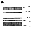
本発明に係るセキュリティエレメントの好適な構成が、分解図の形式で図5(b)に概略示される。
Example 1 Creation and Configuration of Security Element According to the Present Invention A preferred configuration of a security element according to the present invention is schematically illustrated in FIG. 5 (b) in the form of an exploded view.
下方領域(41)は、3Mからの特殊紙7110(3M7110リトペーパー、ホワイト)により形成される。特殊紙は、層順序接着保護層、接着層及び繊維性材料層を既に含む複合材料である。接着層は、製造者の情報によると、基板(例えば、ポリエチレン、若しくはポリプロピレン)に関する接着力が繊維性材料層の強度よりも高い強接着性のアクリル酸系接着剤である。よって繊維性材料は、分離を試みた際に分裂する分離層として作用する。 The lower region (41) is formed by special paper 7110 from 3M (3M7110 lith paper, white). Special paper is a composite material that already includes a layer sequence adhesive protective layer, an adhesive layer and a fibrous material layer. According to manufacturer information, the adhesive layer is a strong adhesive acrylic adhesive whose adhesive strength with respect to the substrate (for example, polyethylene or polypropylene) is higher than the strength of the fibrous material layer. Thus, the fibrous material acts as a separation layer that breaks when separation is attempted.
特殊紙7110は、−40℃から175℃の範囲で温度耐性がある。艶消し表面はプリントが可能であり、光学コードによるプリントのための(更に適切な場合にはイメージをプリントするための)表面を提供する。同時に、特殊紙の個々の領域に対して一意的な特殊紙の繊維構成は、ランダムに方向付けされ及び/又は分布された散乱センタを設けるためのものであり、これにより、300nmから1000nmの範囲の少なくとも一つの波長を有する電磁波放射により特殊紙を照射することで、セキュリティエレメント(若しくはセキュリティエレメントに繋がる目的物)を認証することを可能にする特徴的な散乱信号が生成される。 The special paper 7110 has temperature resistance in the range of −40 ° C. to 175 ° C. The matte surface is printable and provides a surface for printing by optical code (and, where appropriate, for printing an image). At the same time, the special paper fiber composition unique to the individual areas of the special paper is intended to provide randomly oriented and / or distributed scattering centers, which range from 300 nm to 1000 nm. By irradiating special paper with electromagnetic radiation having at least one of the following wavelengths, a characteristic scattered signal that enables authentication of a security element (or an object connected to the security element) is generated.
プライマ(42)は、印刷インクのよりよい接着のための役目を果たす。Hwelett Packard(登録商標)の製品Indigo Topaz 10 Solution MPS−2056−42がここではプライマとして用いられた。プライマは、公知のプリント技術(例えば、デジタルプリント)によって全体領域に渡って特殊紙に塗布された。色変化層(43)及びプリント層(44)は、公知のプリント技術(例えば、デジタルプリント)によってプライマ(42)に塗布される。色変化層(43)は、温度が約120℃を超えると色において透明から黒への不可逆的変化を生じる温度感知変化インクを含む。用いられた変化インクは、製造者Flexo&Gravure Ink.からThermaFlag W/Bの名前で商業的に入手可能である。変化インクは、(図5の例示とは対照的に)コード領域にのみプリントされてもよい。光学コードは、公知のプリント技術(例えば、デジタルプリント)によって変化インク上にプリントされる。複合の最終は、保護層(45)により形成される。ここでは、UPM RaflatacのラミネートPET Overlam RP35が、公知のラミネート方法によって保護薄膜として添付された。
The primer (42) serves for better adhesion of the printing ink. The
図5(a)は、セキュリティエレメント(40)内のスタンプ部分のコースを示す。図3に従って3つのタイプのスタンプ部分が、存在している。放射状セキュリティスタンプ部分(20)、波状セキュリティスタンプ部分(21)、及び、外輪スタンプ部分(22)である。放射状セキュリティスタンプ部分(20)及び外輪スタンプ部分(22)は、図5(a)に概略示すように、全ての層を貫いている。接着保護層(領域(41)の下方部)のみがスタンプ部分から除かれている。波状セキュリティスタンプ部分(21)は特殊紙のみ貫いており、ここでも接着保護層はスタンプ部分から除かれている。 FIG. 5A shows the course of the stamp portion in the security element (40). There are three types of stamp parts according to FIG. A radial security stamp portion (20), a wavy security stamp portion (21), and an outer ring stamp portion (22). The radial security stamp portion (20) and the outer ring stamp portion (22) penetrate through all layers as schematically shown in FIG. 5 (a). Only the adhesive protective layer (below the region (41)) is removed from the stamp portion. The wavy security stamp portion (21) penetrates only the special paper, and again, the adhesive protective layer is removed from the stamp portion.
例2−本発明に係るセキュリティエレメントの特徴的な散乱信号の計測
例1の、本発明に係るセキュリティエレメントの特徴的な散乱信号は、WO2005088533(A1)に記載の方法によって計測された。本発明に係るセキュリティエレメントは、図1に係るコード領域及び散乱領域、並びに図3に係るスタンプ部分の、形式、寸法及び空間的分布を、有するものであった。ここで、散乱領域はスタンプ部分により影響されないものであった。
Example 2 Measurement of Characteristic Scattering Signal of Security Element According to the Present Invention The characteristic scattering signal of the security element according to the present invention in Example 1 was measured by the method described in WO2005088533 (A1). The security element according to the present invention has the type, size, and spatial distribution of the code region and the scattering region according to FIG. 1 and the stamp portion according to FIG. Here, the scattering region was not affected by the stamp portion.
散乱領域は、特許文献1の図1に係る装置を用いて、検出器として、FP−65/5タイプのFlexpoint(登録商標)レーザ(波長650nm、最大出力5mW)及びSTMのFT−30タイプのSi NPNフォトレジスタによって、計測された。
The scattering region is obtained by using an apparatus according to FIG. 1 of
セキュリティエレメント上のレーザのビームプロファイルは、2mmの長さと20μmの幅に関して線形であった。レーザ及び検出器の堅固な構成は、散乱領域の1.5cmの領域に渡ってビームプロファイルの長い側に対して横方向で一定の速度(およそ2cm/秒)でガイドされた。 The beam profile of the laser on the security element was linear with a length of 2 mm and a width of 20 μm. The robust configuration of the laser and detector was guided at a constant velocity (approximately 2 cm / sec) transverse to the long side of the beam profile over a 1.5 cm region of the scattering region.
図6は、任意の単位の移動距離xの関数として、検出器(特許文献1の図1の検出器16b)で検出される散乱放射の強度Iを示す。散乱信号は本発明に係る個々の個別セキュリティエレメントに対して一意的であり、従って認証に用いられ得る。 FIG. 6 shows the intensity I of the scattered radiation detected by the detector (detector 16b of FIG. 1 of Patent Document 1) as a function of the travel distance x in arbitrary units. The scattered signal is unique to each individual security element according to the invention and can therefore be used for authentication.
1・・・ラベルタイプセキュリティエレメント、
2・・・バーコードの形式の光学コードを含む、コード領域、
3・・・実線のフレームにより視覚上マークされた、散乱領域、
10・・・接着保護層、
11・・・接着層、
12・・・繊維性材料含有層、
13・・・プリント層、
14・・・保護層、
20・・・放射状セキュリティスタンプ部分、
21・・・波状セキュリティスタンプ部分、
22・・・外輪スタンプ部分、
31・・・保護層、プリント層及び繊維性材料含有層を貫くスタンプ部分、
32・・・プリント層、繊維性材料含有層、及び接着層を貫くスタンプ部分、
33・・・繊維性材料含有層を部分的に貫くスタンプ部分、
41・・・3Mの特殊紙7110、
42・・・Hwelett Packard(登録商標)のプライマ Indigo Topaz 10 Solution MPS−2056−42、
43・・・Flexo&Gravure Ink.の変化インク ThermaFlag W/B、
44・・・プリントインク
45・・・UPM Raflatacの保護層 PET Overlam RP35。
1 ... Label type security element,
2... Code area including optical code in the form of a barcode,
3 ... Scattered area visually marked by a solid frame,
10: Adhesive protective layer,
11 ... adhesive layer,
12 ... layer containing fibrous material,
13 ... print layer,
14 ... protective layer,
20 ... Radial security stamp part,
21 ... Wavy security stamp part,
22 ... Outer ring stamp part,
31 ... Stamp portion that penetrates the protective layer, the print layer, and the fibrous material-containing layer,
32... A stamp portion penetrating the print layer, the fibrous material-containing layer, and the adhesive layer;
33 ... Stamp portion partially penetrating the fibrous material-containing layer,
41 ... 3M special paper 7110,
42 ... Primer of
43. Flexo & Gravure Ink. Change ink ThermaFlag W / B,
44: Print ink 45: UPM Raflatac protective layer PET Overlam RP35.
Claims (9)
目的物からセキュリティエレメントを非破壊で分離することを回避する手段を含み、
更に、コード領域と視覚的にマークされた散乱領域とを含み、
コード領域は、光学コードを含み、
散乱領域は、散乱領域が電磁波放射により照射されると、セキュリティエレメントに特有の一意的な散乱信号を発生する、ランダムに分布され及び/又は方向付けされた散乱センタを有する
ことを特徴とするセキュリティエレメント。 A security element in the form of a self-adhesive label for attaching a security element to an object,
Including means to avoid non-destructive separation of the security element from the object,
And further includes a code region and a visually marked scattering region;
The code area includes an optical code,
The scatter area has a randomly distributed and / or oriented scatter center that generates a unique scatter signal characteristic of the security element when the scatter area is illuminated by electromagnetic radiation. element.
上記色変化層は、温度限界を超えた及び/又はアンダシュートした際に不可逆的な色変化を発生する
ことを特徴とする請求項1に記載のセキュリティエレメント。 The means for avoiding non-destructive separation of the security element from the object is formed by at least one separation layer, a security stamp portion and / or a color change layer,
The security element according to claim 1, wherein the color change layer generates an irreversible color change when the temperature limit is exceeded and / or undershoots.
電磁波放射による照射にて特徴的な散乱領域を発生する、ランダムに分布された及び/又は方向付けされた散乱センタを設ける繊維性材料層と、
光学コードを含むプリント層と、
保護層と
を少なくとも含む請求項1又は2に記載のセキュリティエレメント。 An adhesive layer that allows the security element to be connected to the object;
A fibrous material layer that provides a randomly distributed and / or oriented scattering center that generates a characteristic scattering region upon irradiation with electromagnetic radiation;
A printed layer containing an optical code;
The security element according to claim 1, comprising at least a protective layer.
(A)セキュリティエレメント上の光学コードを読出し、参照データレコードを判定するステップと、
(B)セキュリティエレメントの特徴的な散乱信号を判定するステップと、
(C)特徴的な散乱信号を参照データレコードと比較するステップと、
(D)上記ステップ(C)の比較の結果に依存させて目的物の認証に関する通知を出力するステップと
を少なくとも含む方法。 A method for identifying and authenticating an object based on the security element according to claim 1, comprising:
(A) reading the optical code on the security element and determining a reference data record;
(B) determining a characteristic scattered signal of the security element;
(C) comparing the characteristic scatter signal with a reference data record;
(D) A method including at least a step of outputting a notification regarding authentication of an object depending on a result of the comparison in the step (C).
Applications Claiming Priority (4)
| Application Number | Priority Date | Filing Date | Title |
|---|---|---|---|
| DE102008007731A DE102008007731B4 (en) | 2008-02-05 | 2008-02-05 | Method and device for identifying and authenticating objects |
| DE102008016803A DE102008016803A1 (en) | 2008-04-02 | 2008-04-02 | Object e.g. person, identifying/authenticating method, involves extracting characteristic feature, and comparing feature with object's characteristic feature that is stored in data base and detected at specific time point |
| DE200810053798 DE102008053798A1 (en) | 2008-10-29 | 2008-10-29 | Object i.e. commodity, identifying and/or authenticating method, involves using electromagnetic radiation reflected by code zone to identify object and using electromagnetic radiation reflected by dispersion zone to authenticate object |
| PCT/EP2009/000451 WO2009097980A2 (en) | 2008-02-05 | 2009-01-24 | Security element |
Publications (2)
| Publication Number | Publication Date |
|---|---|
| JP2011514548A true JP2011514548A (en) | 2011-05-06 |
| JP2011514548A5 JP2011514548A5 (en) | 2012-02-02 |
Family
ID=40886117
Family Applications (1)
| Application Number | Title | Priority Date | Filing Date |
|---|---|---|---|
| JP2010545383A Ceased JP2011514548A (en) | 2008-02-05 | 2009-01-24 | Security element |
Country Status (8)
| Country | Link |
|---|---|
| US (1) | US20110018253A1 (en) |
| EP (1) | EP2259930A2 (en) |
| JP (1) | JP2011514548A (en) |
| KR (1) | KR20100117597A (en) |
| CN (1) | CN101939173B (en) |
| BR (1) | BRPI0907479A2 (en) |
| MX (1) | MX2010008480A (en) |
| WO (1) | WO2009097980A2 (en) |
Cited By (1)
| Publication number | Priority date | Publication date | Assignee | Title |
|---|---|---|---|---|
| WO2013137223A1 (en) * | 2012-03-12 | 2013-09-19 | 株式会社日立製作所 | Counterfeiting-prevention medium, pressure-sensitive adhesive label, transfer foil, and labelled article |
Families Citing this family (11)
| Publication number | Priority date | Publication date | Assignee | Title |
|---|---|---|---|---|
| DE102009052538A1 (en) * | 2009-11-11 | 2011-05-12 | Giesecke & Devrient Gmbh | Producing a provided with colored microwells security element |
| DE102010015014A1 (en) | 2010-04-14 | 2011-10-20 | Bayer Technology Services Gmbh | Optical scanner |
| DE102010020810A1 (en) | 2010-05-18 | 2011-11-24 | Bayer Technology Services Gmbh | Identification of objects |
| DE102010021380A1 (en) | 2010-05-25 | 2011-12-01 | Bayer Technology Services Gmbh | Identification of objects |
| US9436770B2 (en) | 2011-03-10 | 2016-09-06 | Fastechnology Group, LLC | Database systems and methods for consumer packaged goods |
| US20150231896A1 (en) * | 2011-03-10 | 2015-08-20 | Fastechnology Group, LLC | Inverted codes on transparent packaging exterior |
| US10832015B2 (en) | 2011-03-10 | 2020-11-10 | Joseph A. Hattrup Trust Dated July 16, 1996, As Amended | On-the-fly marking systems for consumer packaged goods |
| EP2878453A1 (en) * | 2013-11-28 | 2015-06-03 | Authentic Vision GmbH | Object markings for optical authentication and method for their production |
| EP3154015A1 (en) * | 2015-10-09 | 2017-04-12 | Authentic Vision GmbH | Authentication method for article identifiers |
| CN106585164B (en) * | 2016-11-30 | 2018-01-19 | 东莞市天眼网络科技有限公司 | A kind of method of false-proof texture and anti-counterfeit printed of generating |
| DE102021114841A1 (en) | 2021-06-09 | 2022-12-15 | Schreiner Group Gmbh & Co. Kg | Film composite with protection against manipulation |
Citations (6)
| Publication number | Priority date | Publication date | Assignee | Title |
|---|---|---|---|---|
| JPH08156473A (en) * | 1994-12-06 | 1996-06-18 | Dainippon Printing Co Ltd | Note or the like and forgery preventing method |
| JPH10241000A (en) * | 1997-02-26 | 1998-09-11 | Ricoh Co Ltd | Method and device for special document discrimination and mechanically readable recording medium recording program for execution of the method in computer |
| JP2000293108A (en) * | 1999-04-02 | 2000-10-20 | Kuramoto Sangyo:Kk | Forgery preventing label |
| JP2006235257A (en) * | 2005-02-25 | 2006-09-07 | Nichiei Kako Kk | Label for security |
| JP2007528812A (en) * | 2004-03-12 | 2007-10-18 | インゲニア・テクノロジー・リミテッド | Method and apparatus for creating and subsequently verifying authentic printed articles |
| JP2007529068A (en) * | 2004-03-12 | 2007-10-18 | インゲニア・テクノロジー・リミテッド | Authenticity verification methods, products and equipment |
Family Cites Families (14)
| Publication number | Priority date | Publication date | Assignee | Title |
|---|---|---|---|---|
| IT1023835B (en) * | 1973-05-11 | 1978-05-30 | Dasy Int Sa | DOCUMENT MATERIAL |
| NL9001368A (en) * | 1990-06-15 | 1992-01-02 | Tel Developments B V | SECURITY OF OBJECTS OR DOCUMENTS. |
| GB9116097D0 (en) * | 1991-07-25 | 1991-09-11 | Ordonez Gabriel | Security price or barcode label |
| WO1998057299A1 (en) * | 1997-06-11 | 1998-12-17 | Nova-Technik Entwicklung Von Und Handel Mit Medizinischen Geräten Gmbh | Document with an authentication feature |
| FR2765014B1 (en) * | 1997-06-24 | 2000-02-11 | Rene Boulnois | PAPER DOCUMENT AUTHENTICATION PROCESS, PAPER SECURITY DOCUMENT, AND DEVICE FOR CHECKING THE AUTHENTICITY OF PAPER DOCUMENTS |
| US6904525B1 (en) * | 1997-07-01 | 2005-06-07 | Pitney Bowes Inc. | Method for preventing counterfeiting of articles of manufacture |
| DE19807232C1 (en) * | 1998-02-20 | 1999-07-08 | Schreiner Etiketten | Multi-layer label |
| EP1153373B1 (en) * | 1999-12-08 | 2003-05-28 | Valentin Alexandrovich Mischenko | Method and system for authentication of articles |
| US6550685B1 (en) * | 2000-11-14 | 2003-04-22 | Hewlett-Packard Development Company Lp | Methods and apparatus utilizing visually distinctive barcodes |
| JP4030830B2 (en) * | 2002-08-13 | 2008-01-09 | 日本電気株式会社 | Striped image examination apparatus and striped image examination method |
| CN2715245Y (en) * | 2003-09-22 | 2005-08-03 | 兆日科技(深圳)有限公司 | Texture password label |
| JP2006082481A (en) * | 2004-09-17 | 2006-03-30 | Bridgestone Sports Co Ltd | Method for printing on golf ball box or golf ball packaging material, and golf ball box or golf ball packaging material |
| US7624928B2 (en) * | 2005-11-18 | 2009-12-01 | Fuji Xerox Co., Ltd. | Method and apparatus for making tags, tag, and system for managing articles |
| US20080129037A1 (en) * | 2006-12-01 | 2008-06-05 | Prime Technology Llc | Tagging items with a security feature |
-
2009
- 2009-01-24 US US12/865,578 patent/US20110018253A1/en not_active Abandoned
- 2009-01-24 WO PCT/EP2009/000451 patent/WO2009097980A2/en active Application Filing
- 2009-01-24 MX MX2010008480A patent/MX2010008480A/en unknown
- 2009-01-24 EP EP09707754A patent/EP2259930A2/en not_active Withdrawn
- 2009-01-24 CN CN2009801043143A patent/CN101939173B/en not_active Expired - Fee Related
- 2009-01-24 BR BRPI0907479A patent/BRPI0907479A2/en not_active IP Right Cessation
- 2009-01-24 JP JP2010545383A patent/JP2011514548A/en not_active Ceased
- 2009-01-24 KR KR1020107017453A patent/KR20100117597A/en not_active Application Discontinuation
Patent Citations (6)
| Publication number | Priority date | Publication date | Assignee | Title |
|---|---|---|---|---|
| JPH08156473A (en) * | 1994-12-06 | 1996-06-18 | Dainippon Printing Co Ltd | Note or the like and forgery preventing method |
| JPH10241000A (en) * | 1997-02-26 | 1998-09-11 | Ricoh Co Ltd | Method and device for special document discrimination and mechanically readable recording medium recording program for execution of the method in computer |
| JP2000293108A (en) * | 1999-04-02 | 2000-10-20 | Kuramoto Sangyo:Kk | Forgery preventing label |
| JP2007528812A (en) * | 2004-03-12 | 2007-10-18 | インゲニア・テクノロジー・リミテッド | Method and apparatus for creating and subsequently verifying authentic printed articles |
| JP2007529068A (en) * | 2004-03-12 | 2007-10-18 | インゲニア・テクノロジー・リミテッド | Authenticity verification methods, products and equipment |
| JP2006235257A (en) * | 2005-02-25 | 2006-09-07 | Nichiei Kako Kk | Label for security |
Cited By (1)
| Publication number | Priority date | Publication date | Assignee | Title |
|---|---|---|---|---|
| WO2013137223A1 (en) * | 2012-03-12 | 2013-09-19 | 株式会社日立製作所 | Counterfeiting-prevention medium, pressure-sensitive adhesive label, transfer foil, and labelled article |
Also Published As
| Publication number | Publication date |
|---|---|
| EP2259930A2 (en) | 2010-12-15 |
| WO2009097980A3 (en) | 2009-12-03 |
| BRPI0907479A2 (en) | 2019-02-26 |
| MX2010008480A (en) | 2011-02-23 |
| KR20100117597A (en) | 2010-11-03 |
| US20110018253A1 (en) | 2011-01-27 |
| CN101939173A (en) | 2011-01-05 |
| CN101939173B (en) | 2012-06-20 |
| WO2009097980A2 (en) | 2009-08-13 |
Similar Documents
| Publication | Publication Date | Title |
|---|---|---|
| JP2011514548A (en) | Security element | |
| EP2002385B1 (en) | Method of reading at least one bar code and system for reading a bar code | |
| US9058535B2 (en) | Security barcode | |
| EP1099199B1 (en) | Secure document reader and method therefor | |
| TWI455067B (en) | Authenticity authentication object, authenticity authentication wafer reading device, authenticity identification method, and pattern reading method | |
| EP1941101B1 (en) | Secure article, in particular security and/or valuable document | |
| US9153005B2 (en) | Method and system for authenticating a secure document | |
| US20130300101A1 (en) | Laminated Documents and Cards Including Embedded Security Features | |
| CN104395097B (en) | Safety element including the micro-structural with diffraction structure and the method for manufacturing and verifying | |
| US20110183710A1 (en) | Univocal label to be stored by optical devices, method of production of the same and use thereof in the anticounterfeiting and in the identification of products | |
| JP2011511322A (en) | Security element | |
| IL109199A (en) | Identification system | |
| RU2493968C2 (en) | Security element | |
| KR20200044808A (en) | Laminate, identification certificate, and verification method of identification certificate | |
| CN105190654A (en) | Identification medium, code information reading method, code information reading device, identification medium manufacturing method, and identification medium manufacturing device | |
| US20120162666A1 (en) | Position marking for identifying a surface region and method for identifying/authenticating on the basis of the marked surface region | |
| KR20220052892A (en) | A Film for Preventing Forgery and Falsification and Method of Using there of | |
| JP4264776B2 (en) | Safety protection sheet, authenticity determination method thereof, and authenticity determination device thereof | |
| KR102011604B1 (en) | Method and Apparatus for Providing Authenticity Determination | |
| CN109328360B (en) | Information medium, method of manufacturing the same, method of verifying the same, and verification system | |
| KR20210138967A (en) | Flexible Packaging Comprising Cholesteric Liquid Crystal Layer | |
| JP4572659B2 (en) | Anti-counterfeit card and reading method thereof | |
| KR102242677B1 (en) | Means Preventing Forgery and Falsification Comprising Retro Reflection Materials | |
| JP2007196608A (en) | Article equipped with information recording medium, and reader for the information recording medium | |
| JPH01278397A (en) | Card and method for discriminating kind thereof |
Legal Events
| Date | Code | Title | Description |
|---|---|---|---|
| A521 | Request for written amendment filed |
Free format text: JAPANESE INTERMEDIATE CODE: A523 Effective date: 20111205 |
|
| A621 | Written request for application examination |
Free format text: JAPANESE INTERMEDIATE CODE: A621 Effective date: 20111205 |
|
| A711 | Notification of change in applicant |
Free format text: JAPANESE INTERMEDIATE CODE: A711 Effective date: 20121207 |
|
| A977 | Report on retrieval |
Free format text: JAPANESE INTERMEDIATE CODE: A971007 Effective date: 20130117 |
|
| A131 | Notification of reasons for refusal |
Free format text: JAPANESE INTERMEDIATE CODE: A131 Effective date: 20130122 |
|
| A601 | Written request for extension of time |
Free format text: JAPANESE INTERMEDIATE CODE: A601 Effective date: 20130419 |
|
| A602 | Written permission of extension of time |
Free format text: JAPANESE INTERMEDIATE CODE: A602 Effective date: 20130426 |
|
| A521 | Request for written amendment filed |
Free format text: JAPANESE INTERMEDIATE CODE: A523 Effective date: 20130517 |
|
| A01 | Written decision to grant a patent or to grant a registration (utility model) |
Free format text: JAPANESE INTERMEDIATE CODE: A01 Effective date: 20140311 |
|
| A045 | Written measure of dismissal of application [lapsed due to lack of payment] |
Free format text: JAPANESE INTERMEDIATE CODE: A045 Effective date: 20140729 |