KR20100116583A - Hybrid propulsion systems - Google Patents
Hybrid propulsion systems Download PDFInfo
- Publication number
- KR20100116583A KR20100116583A KR1020107014969A KR20107014969A KR20100116583A KR 20100116583 A KR20100116583 A KR 20100116583A KR 1020107014969 A KR1020107014969 A KR 1020107014969A KR 20107014969 A KR20107014969 A KR 20107014969A KR 20100116583 A KR20100116583 A KR 20100116583A
- Authority
- KR
- South Korea
- Prior art keywords
- propulsion
- energy
- motor
- main
- bus
- Prior art date
Links
Images

Classifications
-
- B—PERFORMING OPERATIONS; TRANSPORTING
- B63—SHIPS OR OTHER WATERBORNE VESSELS; RELATED EQUIPMENT
- B63H—MARINE PROPULSION OR STEERING
- B63H21/00—Use of propulsion power plant or units on vessels
- B63H21/20—Use of propulsion power plant or units on vessels the vessels being powered by combinations of different types of propulsion units
-
- B—PERFORMING OPERATIONS; TRANSPORTING
- B60—VEHICLES IN GENERAL
- B60K—ARRANGEMENT OR MOUNTING OF PROPULSION UNITS OR OF TRANSMISSIONS IN VEHICLES; ARRANGEMENT OR MOUNTING OF PLURAL DIVERSE PRIME-MOVERS IN VEHICLES; AUXILIARY DRIVES FOR VEHICLES; INSTRUMENTATION OR DASHBOARDS FOR VEHICLES; ARRANGEMENTS IN CONNECTION WITH COOLING, AIR INTAKE, GAS EXHAUST OR FUEL SUPPLY OF PROPULSION UNITS IN VEHICLES
- B60K1/00—Arrangement or mounting of electrical propulsion units
- B60K1/02—Arrangement or mounting of electrical propulsion units comprising more than one electric motor
-
- B—PERFORMING OPERATIONS; TRANSPORTING
- B60—VEHICLES IN GENERAL
- B60K—ARRANGEMENT OR MOUNTING OF PROPULSION UNITS OR OF TRANSMISSIONS IN VEHICLES; ARRANGEMENT OR MOUNTING OF PLURAL DIVERSE PRIME-MOVERS IN VEHICLES; AUXILIARY DRIVES FOR VEHICLES; INSTRUMENTATION OR DASHBOARDS FOR VEHICLES; ARRANGEMENTS IN CONNECTION WITH COOLING, AIR INTAKE, GAS EXHAUST OR FUEL SUPPLY OF PROPULSION UNITS IN VEHICLES
- B60K5/00—Arrangement or mounting of internal-combustion or jet-propulsion units
- B60K5/08—Arrangement or mounting of internal-combustion or jet-propulsion units comprising more than one engine
-
- B—PERFORMING OPERATIONS; TRANSPORTING
- B60—VEHICLES IN GENERAL
- B60K—ARRANGEMENT OR MOUNTING OF PROPULSION UNITS OR OF TRANSMISSIONS IN VEHICLES; ARRANGEMENT OR MOUNTING OF PLURAL DIVERSE PRIME-MOVERS IN VEHICLES; AUXILIARY DRIVES FOR VEHICLES; INSTRUMENTATION OR DASHBOARDS FOR VEHICLES; ARRANGEMENTS IN CONNECTION WITH COOLING, AIR INTAKE, GAS EXHAUST OR FUEL SUPPLY OF PROPULSION UNITS IN VEHICLES
- B60K6/00—Arrangement or mounting of plural diverse prime-movers for mutual or common propulsion, e.g. hybrid propulsion systems comprising electric motors and internal combustion engines ; Control systems therefor, i.e. systems controlling two or more prime movers, or controlling one of these prime movers and any of the transmission, drive or drive units Informative references: mechanical gearings with secondary electric drive F16H3/72; arrangements for handling mechanical energy structurally associated with the dynamo-electric machine H02K7/00; machines comprising structurally interrelated motor and generator parts H02K51/00; dynamo-electric machines not otherwise provided for in H02K see H02K99/00
- B60K6/20—Arrangement or mounting of plural diverse prime-movers for mutual or common propulsion, e.g. hybrid propulsion systems comprising electric motors and internal combustion engines ; Control systems therefor, i.e. systems controlling two or more prime movers, or controlling one of these prime movers and any of the transmission, drive or drive units Informative references: mechanical gearings with secondary electric drive F16H3/72; arrangements for handling mechanical energy structurally associated with the dynamo-electric machine H02K7/00; machines comprising structurally interrelated motor and generator parts H02K51/00; dynamo-electric machines not otherwise provided for in H02K see H02K99/00 the prime-movers consisting of electric motors and internal combustion engines, e.g. HEVs
- B60K6/42—Arrangement or mounting of plural diverse prime-movers for mutual or common propulsion, e.g. hybrid propulsion systems comprising electric motors and internal combustion engines ; Control systems therefor, i.e. systems controlling two or more prime movers, or controlling one of these prime movers and any of the transmission, drive or drive units Informative references: mechanical gearings with secondary electric drive F16H3/72; arrangements for handling mechanical energy structurally associated with the dynamo-electric machine H02K7/00; machines comprising structurally interrelated motor and generator parts H02K51/00; dynamo-electric machines not otherwise provided for in H02K see H02K99/00 the prime-movers consisting of electric motors and internal combustion engines, e.g. HEVs characterised by the architecture of the hybrid electric vehicle
- B60K6/48—Parallel type
-
- B—PERFORMING OPERATIONS; TRANSPORTING
- B60—VEHICLES IN GENERAL
- B60L—PROPULSION OF ELECTRICALLY-PROPELLED VEHICLES; SUPPLYING ELECTRIC POWER FOR AUXILIARY EQUIPMENT OF ELECTRICALLY-PROPELLED VEHICLES; ELECTRODYNAMIC BRAKE SYSTEMS FOR VEHICLES IN GENERAL; MAGNETIC SUSPENSION OR LEVITATION FOR VEHICLES; MONITORING OPERATING VARIABLES OF ELECTRICALLY-PROPELLED VEHICLES; ELECTRIC SAFETY DEVICES FOR ELECTRICALLY-PROPELLED VEHICLES
- B60L1/00—Supplying electric power to auxiliary equipment of vehicles
-
- B—PERFORMING OPERATIONS; TRANSPORTING
- B60—VEHICLES IN GENERAL
- B60L—PROPULSION OF ELECTRICALLY-PROPELLED VEHICLES; SUPPLYING ELECTRIC POWER FOR AUXILIARY EQUIPMENT OF ELECTRICALLY-PROPELLED VEHICLES; ELECTRODYNAMIC BRAKE SYSTEMS FOR VEHICLES IN GENERAL; MAGNETIC SUSPENSION OR LEVITATION FOR VEHICLES; MONITORING OPERATING VARIABLES OF ELECTRICALLY-PROPELLED VEHICLES; ELECTRIC SAFETY DEVICES FOR ELECTRICALLY-PROPELLED VEHICLES
- B60L50/00—Electric propulsion with power supplied within the vehicle
- B60L50/10—Electric propulsion with power supplied within the vehicle using propulsion power supplied by engine-driven generators, e.g. generators driven by combustion engines
- B60L50/15—Electric propulsion with power supplied within the vehicle using propulsion power supplied by engine-driven generators, e.g. generators driven by combustion engines with additional electric power supply
-
- B—PERFORMING OPERATIONS; TRANSPORTING
- B60—VEHICLES IN GENERAL
- B60L—PROPULSION OF ELECTRICALLY-PROPELLED VEHICLES; SUPPLYING ELECTRIC POWER FOR AUXILIARY EQUIPMENT OF ELECTRICALLY-PROPELLED VEHICLES; ELECTRODYNAMIC BRAKE SYSTEMS FOR VEHICLES IN GENERAL; MAGNETIC SUSPENSION OR LEVITATION FOR VEHICLES; MONITORING OPERATING VARIABLES OF ELECTRICALLY-PROPELLED VEHICLES; ELECTRIC SAFETY DEVICES FOR ELECTRICALLY-PROPELLED VEHICLES
- B60L50/00—Electric propulsion with power supplied within the vehicle
- B60L50/10—Electric propulsion with power supplied within the vehicle using propulsion power supplied by engine-driven generators, e.g. generators driven by combustion engines
- B60L50/16—Electric propulsion with power supplied within the vehicle using propulsion power supplied by engine-driven generators, e.g. generators driven by combustion engines with provision for separate direct mechanical propulsion
-
- B—PERFORMING OPERATIONS; TRANSPORTING
- B60—VEHICLES IN GENERAL
- B60L—PROPULSION OF ELECTRICALLY-PROPELLED VEHICLES; SUPPLYING ELECTRIC POWER FOR AUXILIARY EQUIPMENT OF ELECTRICALLY-PROPELLED VEHICLES; ELECTRODYNAMIC BRAKE SYSTEMS FOR VEHICLES IN GENERAL; MAGNETIC SUSPENSION OR LEVITATION FOR VEHICLES; MONITORING OPERATING VARIABLES OF ELECTRICALLY-PROPELLED VEHICLES; ELECTRIC SAFETY DEVICES FOR ELECTRICALLY-PROPELLED VEHICLES
- B60L58/00—Methods or circuit arrangements for monitoring or controlling batteries or fuel cells, specially adapted for electric vehicles
- B60L58/10—Methods or circuit arrangements for monitoring or controlling batteries or fuel cells, specially adapted for electric vehicles for monitoring or controlling batteries
- B60L58/18—Methods or circuit arrangements for monitoring or controlling batteries or fuel cells, specially adapted for electric vehicles for monitoring or controlling batteries of two or more battery modules
-
- B—PERFORMING OPERATIONS; TRANSPORTING
- B60—VEHICLES IN GENERAL
- B60W—CONJOINT CONTROL OF VEHICLE SUB-UNITS OF DIFFERENT TYPE OR DIFFERENT FUNCTION; CONTROL SYSTEMS SPECIALLY ADAPTED FOR HYBRID VEHICLES; ROAD VEHICLE DRIVE CONTROL SYSTEMS FOR PURPOSES NOT RELATED TO THE CONTROL OF A PARTICULAR SUB-UNIT
- B60W10/00—Conjoint control of vehicle sub-units of different type or different function
- B60W10/04—Conjoint control of vehicle sub-units of different type or different function including control of propulsion units
- B60W10/06—Conjoint control of vehicle sub-units of different type or different function including control of propulsion units including control of combustion engines
-
- B—PERFORMING OPERATIONS; TRANSPORTING
- B60—VEHICLES IN GENERAL
- B60W—CONJOINT CONTROL OF VEHICLE SUB-UNITS OF DIFFERENT TYPE OR DIFFERENT FUNCTION; CONTROL SYSTEMS SPECIALLY ADAPTED FOR HYBRID VEHICLES; ROAD VEHICLE DRIVE CONTROL SYSTEMS FOR PURPOSES NOT RELATED TO THE CONTROL OF A PARTICULAR SUB-UNIT
- B60W10/00—Conjoint control of vehicle sub-units of different type or different function
- B60W10/04—Conjoint control of vehicle sub-units of different type or different function including control of propulsion units
- B60W10/08—Conjoint control of vehicle sub-units of different type or different function including control of propulsion units including control of electric propulsion units, e.g. motors or generators
-
- B—PERFORMING OPERATIONS; TRANSPORTING
- B60—VEHICLES IN GENERAL
- B60W—CONJOINT CONTROL OF VEHICLE SUB-UNITS OF DIFFERENT TYPE OR DIFFERENT FUNCTION; CONTROL SYSTEMS SPECIALLY ADAPTED FOR HYBRID VEHICLES; ROAD VEHICLE DRIVE CONTROL SYSTEMS FOR PURPOSES NOT RELATED TO THE CONTROL OF A PARTICULAR SUB-UNIT
- B60W10/00—Conjoint control of vehicle sub-units of different type or different function
- B60W10/30—Conjoint control of vehicle sub-units of different type or different function including control of auxiliary equipment, e.g. air-conditioning compressors or oil pumps
-
- B—PERFORMING OPERATIONS; TRANSPORTING
- B60—VEHICLES IN GENERAL
- B60W—CONJOINT CONTROL OF VEHICLE SUB-UNITS OF DIFFERENT TYPE OR DIFFERENT FUNCTION; CONTROL SYSTEMS SPECIALLY ADAPTED FOR HYBRID VEHICLES; ROAD VEHICLE DRIVE CONTROL SYSTEMS FOR PURPOSES NOT RELATED TO THE CONTROL OF A PARTICULAR SUB-UNIT
- B60W20/00—Control systems specially adapted for hybrid vehicles
-
- B—PERFORMING OPERATIONS; TRANSPORTING
- B63—SHIPS OR OTHER WATERBORNE VESSELS; RELATED EQUIPMENT
- B63B—SHIPS OR OTHER WATERBORNE VESSELS; EQUIPMENT FOR SHIPPING
- B63B35/00—Vessels or similar floating structures specially adapted for specific purposes and not otherwise provided for
- B63B35/66—Tugs
-
- B—PERFORMING OPERATIONS; TRANSPORTING
- B60—VEHICLES IN GENERAL
- B60L—PROPULSION OF ELECTRICALLY-PROPELLED VEHICLES; SUPPLYING ELECTRIC POWER FOR AUXILIARY EQUIPMENT OF ELECTRICALLY-PROPELLED VEHICLES; ELECTRODYNAMIC BRAKE SYSTEMS FOR VEHICLES IN GENERAL; MAGNETIC SUSPENSION OR LEVITATION FOR VEHICLES; MONITORING OPERATING VARIABLES OF ELECTRICALLY-PROPELLED VEHICLES; ELECTRIC SAFETY DEVICES FOR ELECTRICALLY-PROPELLED VEHICLES
- B60L2200/00—Type of vehicles
- B60L2200/32—Waterborne vessels
-
- B—PERFORMING OPERATIONS; TRANSPORTING
- B60—VEHICLES IN GENERAL
- B60L—PROPULSION OF ELECTRICALLY-PROPELLED VEHICLES; SUPPLYING ELECTRIC POWER FOR AUXILIARY EQUIPMENT OF ELECTRICALLY-PROPELLED VEHICLES; ELECTRODYNAMIC BRAKE SYSTEMS FOR VEHICLES IN GENERAL; MAGNETIC SUSPENSION OR LEVITATION FOR VEHICLES; MONITORING OPERATING VARIABLES OF ELECTRICALLY-PROPELLED VEHICLES; ELECTRIC SAFETY DEVICES FOR ELECTRICALLY-PROPELLED VEHICLES
- B60L2220/00—Electrical machine types; Structures or applications thereof
- B60L2220/40—Electrical machine applications
- B60L2220/42—Electrical machine applications with use of more than one motor
-
- B—PERFORMING OPERATIONS; TRANSPORTING
- B60—VEHICLES IN GENERAL
- B60Y—INDEXING SCHEME RELATING TO ASPECTS CROSS-CUTTING VEHICLE TECHNOLOGY
- B60Y2200/00—Type of vehicle
- B60Y2200/40—Special vehicles
- B60Y2200/42—Amphibious vehicles
-
- B—PERFORMING OPERATIONS; TRANSPORTING
- B63—SHIPS OR OTHER WATERBORNE VESSELS; RELATED EQUIPMENT
- B63H—MARINE PROPULSION OR STEERING
- B63H21/00—Use of propulsion power plant or units on vessels
- B63H21/20—Use of propulsion power plant or units on vessels the vessels being powered by combinations of different types of propulsion units
- B63H2021/202—Use of propulsion power plant or units on vessels the vessels being powered by combinations of different types of propulsion units of hybrid electric type
- B63H2021/205—Use of propulsion power plant or units on vessels the vessels being powered by combinations of different types of propulsion units of hybrid electric type the second power unit being of the internal combustion engine type, or the like, e.g. a Diesel engine
-
- Y—GENERAL TAGGING OF NEW TECHNOLOGICAL DEVELOPMENTS; GENERAL TAGGING OF CROSS-SECTIONAL TECHNOLOGIES SPANNING OVER SEVERAL SECTIONS OF THE IPC; TECHNICAL SUBJECTS COVERED BY FORMER USPC CROSS-REFERENCE ART COLLECTIONS [XRACs] AND DIGESTS
- Y02—TECHNOLOGIES OR APPLICATIONS FOR MITIGATION OR ADAPTATION AGAINST CLIMATE CHANGE
- Y02T—CLIMATE CHANGE MITIGATION TECHNOLOGIES RELATED TO TRANSPORTATION
- Y02T10/00—Road transport of goods or passengers
- Y02T10/60—Other road transportation technologies with climate change mitigation effect
- Y02T10/62—Hybrid vehicles
-
- Y—GENERAL TAGGING OF NEW TECHNOLOGICAL DEVELOPMENTS; GENERAL TAGGING OF CROSS-SECTIONAL TECHNOLOGIES SPANNING OVER SEVERAL SECTIONS OF THE IPC; TECHNICAL SUBJECTS COVERED BY FORMER USPC CROSS-REFERENCE ART COLLECTIONS [XRACs] AND DIGESTS
- Y02—TECHNOLOGIES OR APPLICATIONS FOR MITIGATION OR ADAPTATION AGAINST CLIMATE CHANGE
- Y02T—CLIMATE CHANGE MITIGATION TECHNOLOGIES RELATED TO TRANSPORTATION
- Y02T10/00—Road transport of goods or passengers
- Y02T10/60—Other road transportation technologies with climate change mitigation effect
- Y02T10/64—Electric machine technologies in electromobility
-
- Y—GENERAL TAGGING OF NEW TECHNOLOGICAL DEVELOPMENTS; GENERAL TAGGING OF CROSS-SECTIONAL TECHNOLOGIES SPANNING OVER SEVERAL SECTIONS OF THE IPC; TECHNICAL SUBJECTS COVERED BY FORMER USPC CROSS-REFERENCE ART COLLECTIONS [XRACs] AND DIGESTS
- Y02—TECHNOLOGIES OR APPLICATIONS FOR MITIGATION OR ADAPTATION AGAINST CLIMATE CHANGE
- Y02T—CLIMATE CHANGE MITIGATION TECHNOLOGIES RELATED TO TRANSPORTATION
- Y02T10/00—Road transport of goods or passengers
- Y02T10/60—Other road transportation technologies with climate change mitigation effect
- Y02T10/70—Energy storage systems for electromobility, e.g. batteries
-
- Y—GENERAL TAGGING OF NEW TECHNOLOGICAL DEVELOPMENTS; GENERAL TAGGING OF CROSS-SECTIONAL TECHNOLOGIES SPANNING OVER SEVERAL SECTIONS OF THE IPC; TECHNICAL SUBJECTS COVERED BY FORMER USPC CROSS-REFERENCE ART COLLECTIONS [XRACs] AND DIGESTS
- Y02—TECHNOLOGIES OR APPLICATIONS FOR MITIGATION OR ADAPTATION AGAINST CLIMATE CHANGE
- Y02T—CLIMATE CHANGE MITIGATION TECHNOLOGIES RELATED TO TRANSPORTATION
- Y02T10/00—Road transport of goods or passengers
- Y02T10/60—Other road transportation technologies with climate change mitigation effect
- Y02T10/7072—Electromobility specific charging systems or methods for batteries, ultracapacitors, supercapacitors or double-layer capacitors
-
- Y—GENERAL TAGGING OF NEW TECHNOLOGICAL DEVELOPMENTS; GENERAL TAGGING OF CROSS-SECTIONAL TECHNOLOGIES SPANNING OVER SEVERAL SECTIONS OF THE IPC; TECHNICAL SUBJECTS COVERED BY FORMER USPC CROSS-REFERENCE ART COLLECTIONS [XRACs] AND DIGESTS
- Y02—TECHNOLOGIES OR APPLICATIONS FOR MITIGATION OR ADAPTATION AGAINST CLIMATE CHANGE
- Y02T—CLIMATE CHANGE MITIGATION TECHNOLOGIES RELATED TO TRANSPORTATION
- Y02T70/00—Maritime or waterways transport
- Y02T70/50—Measures to reduce greenhouse gas emissions related to the propulsion system
- Y02T70/5218—Less carbon-intensive fuels, e.g. natural gas, biofuels
- Y02T70/5236—Renewable or hybrid-electric solutions
Abstract
해양 선박 및 그 외 다른 가변 수요 추진 적용예에 이용을 위한 하이브리드 추진 및 에너지 관리 시스템은 추진 수요의 범위를 넘어 효율적인 시스템 작동을 제공하고 다중 작동 모드들을 동역학적으로 실행하도록 다양한 에너지소스들로부터 에너지를 끌어당기고 감시하며, 추진 부하 요구, 호텔 부하 및 보조 에너지 수요에 응답하여 다양한 에너지 소스의 출력 및 작동을 변경한다. 추진 시스템은 두 개 이상의 추진 소스들을 구비하며, 공통 출력 샤프트를 구동하도록 배열된 하나 이상의 모터-발전기 유닛과 하나 이상의 주 추진 엔진을 포함하고, 에너지 관리 시스템은 추진 수요를 충족시키기 위해 두 개의 소스들 각각에 대한 작동을 동적으로 변화시킨다. 주 추진 엔진과 모터-발전기 유닛은 독립적으로 및 동시적으로 공통 출력 샤프트를 구동할 수 있다. 모터-발전기 유닛은 에너지를 에너지 분배 시스템에 공급하기 위한 발전기로써 또는 출력 샤프트를 구동하는 모터로써 작동하도록 이용될 수 있다.Hybrid propulsion and energy management systems for use in marine vessels and other variable demand propulsion applications extend energy from a variety of energy sources to provide efficient system operation beyond the propulsion demand and to dynamically execute multiple modes of operation. It draws and monitors and changes the output and operation of various energy sources in response to propulsion load demands, hotel loads and auxiliary energy demands. The propulsion system has two or more propulsion sources and includes one or more motor-generator units and one or more main propulsion engines arranged to drive a common output shaft, the energy management system having two sources to meet the propulsion demands. Dynamically change the behavior for each. The main propulsion engine and motor-generator unit can independently and simultaneously drive a common output shaft. The motor-generator unit can be used to operate as a generator for supplying energy to the energy distribution system or as a motor to drive the output shaft.
Description
본 발명은 작동 동안 가변하는 동력 요건을 가진 해양 선박에서 이용되는 하이브리드 추진 시스템에 관한 것으로, 하이브리드 추진 시스템 내에서 에너지 흐름을 관리하기 위한 시스템 및 방법에 관한 것이다.
FIELD OF THE INVENTION The present invention relates to hybrid propulsion systems for use in marine vessels having varying power requirements during operation, and to systems and methods for managing energy flow within hybrid propulsion systems.
연료 소모와 유해 방출물을 감소시킨 해양 선박을 위한 그리고 그 외 중량이 있는 업무를 하는 다양한 수요 적용예을 위한 추진 시스템의 시행 및 개발에 대한 에너지 보존 및 오염 제어 노력이 있어왔다. 디젤-전기 추진은 오랜 기간 동안 잠수함 및 수상 선박에 이용되어왔다. 일반적으로, 디젤 엔진은 전기 발전기에 결합하며, 이 엔진은 프로펠러와 기계적으로 결합된 전기 모터에 전력을 제공한다. Energy conservation and pollution control efforts have been undertaken to implement and develop propulsion systems for marine vessels that have reduced fuel consumption and hazardous emissions, and for other demanding applications with heavy-duty services. Diesel-electric propulsion has long been used in submarines and watercraft. In general, diesel engines are coupled to an electric generator, which provides power to an electric motor mechanically coupled with a propeller.
함께 또는 개별적으로 추진을 위해 두 개 이상의 개별 전력 소스를 이용하는 다양한 유형의 결합된 사이클 추진 시스템이 제공되어왔다. 예를 들면, CODOG(COmbined Diesel Or Gas) 장치가 동시에 디젤 엔진과 가스 터빈 엔진 모두에 의해서가 아니라, 디젤 엔진에 의해 또는 가스 터빈 엔진에 의해 추진력을 제공한다. 이와 대조적으로, CODAG(COmbined Diesel And Gas) 장치는 독립적으로뿐만 아니라 동시에 두 유형의 추진을 하게 한다. 디젤, 디젤-전기, 가스 터빈과 증기 터빈 추진의 다양한 조합을 이용한 결합된 사이클 장치가 이용되어왔다. Royal New Zealand Navy의 다중-롤 선박 HMNZS Canterbury는 Combined Diesel Electric and Diesel (CODLAD) 추진 시스템을 가진다.Various types of combined cycle propulsion systems have been provided that utilize two or more separate power sources for propulsion together or separately. For example, (CO mbined iesel D O r G as) CODOG device is at the same time, not by both diesel and gas turbine engines, and provides a driving force by the gas turbine engine or by a diesel engine. In contrast, CODAG (CO mbined iesel D A G as nd) apparatus, as well as independently and simultaneously makes the two types of propulsion. Combined cycle devices have been used with various combinations of diesel, diesel-electric, gas turbine and steam turbine propulsion. Royal New Zealand Navy's multi-roll ship HMNZS Canterbury has a Combined Diesel Electric and Diesel (CODLAD) propulsion system.
U.S. Patent 7,207,852에는 선박 추진 시스템이 개시되며, 이 시스템 내에 기계적 구동 샤프트는 선체를 관통하여 연장되고 선박을 관통하여 기계적 구동 샤프트가 연장된 선박으로 외부 하우징 내에서 전기 모터에 의해서 또는 선박 내부에 위치된 최초 구동기에 의해서 구동된다. 이 장치는 별도의 공간 형성 없이 선박의 제한된 내부 공간 범위 내에서 전기 모터를 수용하여 조합된 사이클 작동의 이익을 제공한다. 2005년 2월호 Journal of the JIME Vol. 40에서 설명된 저자가 Ueda, N. 및 Numaguchi, Hajime인, The First Hybrid CRP-POD Driven Fast ROPAX Ferry in the World에서는 전기 선박 추진 유닛의 유사한 형태가 종래의 디젤 추진 시스템과 결합된다. U.S. Patent 7,207,852 discloses a ship propulsion system, in which the mechanical drive shaft extends through the hull and extends through the ship, where the mechanical drive shaft extends, the first being positioned by an electric motor or inside the ship in an outer housing. Driven by a driver. The device provides the benefit of combined cycle operation by accommodating an electric motor within the ship's limited internal space without creating additional space. February 2005 Journal of the JIME Vol. In The First Hybrid CRP-POD Driven Fast ROPAX Ferry in the World, authors described at 40 Ueda, N. and Numaguchi, Hajime, a similar form of electric ship propulsion unit is combined with conventional diesel propulsion systems.
해양 선박 적용을 위한 조합된 추진 시스템을 제공하려는 노력들에 불과하고, 이 조합된 시스템은, 특히 총 연료 및 성능 효율, 방출 감소, 변동 및 추진 수요 상황에 대한 범위에 대해 효과적으로 신속하게 응답하는 능력에 대하여 실망스러운 결과를 나타낸다.
It is merely an effort to provide a combined propulsion system for marine vessel applications, which combines the ability to respond quickly and effectively to a range of total fuel and performance efficiencies, emission reductions, fluctuations and propulsion demands. It shows disappointing results.
본 발명인 하이브리드 추진 시스템에서, 추진을 위한 에너지가 직접적인 기계적 배열에서 주 엔진들(예를 들면, 디젤 엔진 또는 그 외 다른 유형의 원동기 엔진)에 의해서, 모터-발전기(예를 들면, 디젤-전기 배열에서 디젤-발전기)들에 의해서, 모든-전기 배열에서 저장 배터리들에 의해서 또는 이 에너지 소스들의 임의의 조합에 의해서 공급될 수 있다. 가령 윈치들 및 그 외 다른 작동 장비와 같은 선박 호텔 부하 및 보조 에너지 수요가 하이브리드 에너지 소스에 의해 충족될 수도 있다. 에너지 관리 시스템은 이용가능한 에너지 선택 범위 중에서 또는 선택 범위 사이에서 스위치되고 추진 부하 수요, 호텔 부하들 및/또는 보조 에너지 수요들에 응답하여 다중 작동 모드를 실행하는 다양한 에너지 소스의 출력 및 작동을 변경한다. 다중 작동 모드들에 걸친 추진 시스템의 작동에 의해 다양한 조건에 대한 추진 시스템의 응답이 최적화되게 하고, 개별적으로 다양한 에너지 소스의 성능 효율과 연료 효율 및 연료 효율과 전체 시스템의 성능 효율과 연료 효율을 향상시키며, 이 추진 시스템의 작동은 방출을 감소시키고 신속하고 효율적으로 에너지 수요 범위를 충족시킨다. 몇몇 실시예에서, 자동화된 에너지 관린 시스템(EMS)은 시스템 작동 모드의 가변하는 범위를 연속적이고 실질적이게 실행하며 추진력과 그 외 다른 에너지 수요를 충족시키기 위해 다양한 에너지 소스에 대한 작동을 기능적으로 변화시킨다.In the hybrid propulsion system of the present invention, the energy for propulsion is generated by a motor-generator (eg, diesel-electric arrangement) by means of main engines (eg, diesel engines or other types of prime mover engines) in a direct mechanical arrangement. Diesel generators), storage batteries in an all-electrical arrangement, or any combination of these energy sources. Ship hotel loads and auxiliary energy demands such as winches and other operating equipment may be met by hybrid energy sources. The energy management system switches between and among the available energy selection ranges and changes the output and operation of various energy sources executing multiple modes of operation in response to propulsion load demands, hotel loads and / or auxiliary energy demands. . The operation of the propulsion system across multiple operating modes optimizes the response of the propulsion system to various conditions and improves the performance and fuel efficiency and fuel efficiency of the various energy sources individually and the performance and fuel efficiency of the overall system. The operation of this propulsion system reduces emissions and meets energy demand ranges quickly and efficiently. In some embodiments, an automated energy management system (EMS) continuously and substantially implements a varying range of system operating modes and functionally alters operation for various energy sources to meet propulsion and other energy demands. .
본 발명인 하이브리드 추진 시스템은 해양 선박 추진 시스템과 관련하여 설명되며 해양 추진 플랜트 배열에 대한 창의성 있는 접근을 포함한다. 특히, 이 시스템은, 일반적으로 고 전력이 간헐적인 시간 동안 요구되는, 고 추진 부하 용량 요건 및 가변 전력 수요를 가지는 선박에 대한 이용에 적합하다. 하이브리드 추진 시스템은 2개의 드라이브라인, 2개의 프로펠러 장치에서 모터-발전기 유닛과 협력하여 작동하는 주 엔진(예를 들면, 디젤 엔진들)과 관련하여 설명되며, 특히 터그보트와 같은 해양 선박에 대한 이용을 위해 고안된다. 그러나, 하이브리드 추진 시스템은 그 외 다른 해양 선박들과 가변 전력이 요구되는 적용례에 채용될 수 있고, 이 시스템은 단일 엔진, 단일 드라이브라인 및/또는 단일 프로펠러 장치에서 실행될 수 있다. 추가적인 엔진 수요가 충족될 수 있고, 추가적인 에너지 소스도 본 발명인 시스템에서 포함될 수 있다. The inventors' hybrid propulsion system is described in connection with a marine vessel propulsion system and includes a creative approach to the marine propulsion plant arrangement. In particular, this system is suitable for use on ships with high propulsion load capacity requirements and variable power demand, where high power is typically required for intermittent times. Hybrid propulsion systems are described in relation to main engines (eg diesel engines) operating in cooperation with motor-generator units in two drivelines, two propeller units, in particular for use on offshore vessels such as tugboats. Is designed for. However, hybrid propulsion systems can be employed in other marine vessels and applications where variable power is required, which can be implemented in a single engine, single driveline and / or single propeller arrangement. Additional engine demands may be met and additional energy sources may be included in the inventors' system.
하이브리드 추진 시스템은 효율적으로 에너지를 생성, 저장 및 이용하는 기능을 제공하며, 배열과 관련하여 상당한 융통성을 제공한다. 본 명세서에서 설명된 하이브리드 추진 및 에너지 관린 시스템은 다중 주 구동 엔진에 대한 불필요한 작동을 최소화하며, 엔진들의 고 효율 범위 내에서만 주 구동 엔진들을 작동하며, 이 시스템에 의해 단일 또는 비교적 작은 수의 엔진들이 많은 부하에 전력을 제공하게 하며, 연료 소모와 유해한 물질 방출을 감소시킨다. 이 디자인은 일반적으로 완전한-디젤, 디젤-전기 및 모든 전기 추진을 포함하고, 전기 에너지 저장 및 향상된 전력 변환 기법을 이용하는 융통성 있는 배열을 제공한다. 선상과 해안 소스와 같은 보조 소스로부터 소스들이 이용가능할 때, 이 시스템은 선택적인 에너지 소스에 대한 이용을 포함한다. 시스템의 융통성에 의해 시스템이 선박 임무 사이클과 전력 요건에 대한 넓은 범위를 충족시키도록 형성되게 한다.Hybrid propulsion systems provide the ability to efficiently generate, store, and utilize energy, and provide considerable flexibility with regard to arrangement. The hybrid propulsion and energy management system described herein minimizes unnecessary operation on multiple main drive engines and operates the main drive engines only within the high efficiency range of the engines, whereby a single or relatively small number of engines It provides power for many loads and reduces fuel consumption and harmful emissions. This design generally includes full-diesel, diesel-electric and all electric propulsion, and provides a flexible arrangement using electrical energy storage and advanced power conversion techniques. When sources are available from auxiliary sources, such as onboard and offshore sources, the system includes the use of optional energy sources. The flexibility of the system allows the system to be configured to meet a wide range of ship mission cycles and power requirements.
추진 전력 소스와 제어 기술에 대한 신규한 장치가 에너지 관리 시스템(Energy Management System)(EMS)에 의해 작동될 수 있고, 이 시스템은 조작자 제어 입력을 전혀 또는 거의 요구하지 않는다. 몇몇 실시예에 따르면, EMS는 전력 플랜트를 형성할 수 있고, "인공지능(intelligent)" 부하 분배, 에너지 분배와 토크 최적화 기술을 채용함으로써 넓은 범위의 추진력 및 그 외 다른 에너지 수요에 걸쳐서 고효율을 위한 추진력에 대한 다중 소스를 구비한다. 이 방식에서, 선박의 주 추진 엔진(들)(예를 들면, 디젤 엔진들)과 그 외 다른 엔진 소스가 넓은 범위의 요구된 샤프트 출력 속도의 전반에 걸쳐서 고 효율로 이용된다. 일반적으로, 주 추진 엔진(들), 모터-발전기(들), 보조 발전기(들) 및 저장 배터리(들)가 가령 "호텔(hotel)" 부하(조명, 공기 조절, 선박 내 물 펌프, 등등), 윈치와 이와 유사한 것과 같은 전력을 요하는 보조 장비와 같은 보조 수요 및 추진력 모두를 위해 전력을 제공한다. Novel devices for propulsion power sources and control technology can be operated by Energy Management System (EMS), which requires little or no operator control input. According to some embodiments, an EMS can form a power plant and employ "intelligent" load distribution, energy distribution and torque optimization techniques to achieve high efficiency over a wide range of propulsion and other energy demands. With multiple sources for propulsion. In this way, the ship's main propulsion engine (s) (eg diesel engines) and other engine sources are used at high efficiency over a wide range of required shaft output speeds. Generally, the main propulsion engine (s), motor-generator (s), auxiliary generator (s) and storage battery (s) are for example "hotel" loads (lighting, air conditioning, water pumps on board, etc.) It provides power for both auxiliary demand and propulsion, such as auxiliary equipment that requires power, such as winches and similar.
주 추진 엔진(예를 들면, 디젤 엔진들)이 예를 들면, 클러치 장치에 의해 드라이브라인에 기계적으로 결합되고, 또한 공통 드라이브라인 상에 배열된 모터-발전기에 연결된다. 주 추진 엔진들에서 출력이 선택되거나 실행된 부하 수요와 작동 모드에 따라, 추진 출력 샤프트(예를 들면, 프로펠러) 또는 모터-발전기(들), 또는 이 둘 모두를 구동할 수 있다. 일반적으로 모터-발전기(들)이 선박들의 추진 수요 또는 부하와 실행된 작동 모드에 따라, 에너지를 전기 분배 시스템(예를 들면, 버스)에 공급하는 발전기들로써 또는 출력 샤프트를 구동시키는 모터들로써 작동하도록 이용될 수 있다. The main propulsion engine (eg diesel engines) is mechanically coupled to the driveline, for example by a clutch arrangement, and also connected to a motor-generator arranged on a common driveline. Depending on the load demand and operating mode in which the output is selected or executed in the main propulsion engines, it is possible to drive the propulsion output shaft (eg propeller) or motor-generator (s), or both. In general, the motor-generator (s) to operate as generators that supply energy to an electrical distribution system (eg bus) or as motors that drive the output shaft, depending on the propulsion demands or loads of the vessels and the operating mode performed. Can be used.
이 시스템을 통한 전기 에너지 분배가 공통 버스, 일반적으로 DC버스로부터 및 DC버스로 공급되며, 선호적으로 DC버스 및 추진 모터-발전기 사이 에너지 흐름은 양방향이다. 모터-발전기가 초과 생성 용량을 가질 때, 양방향 흐름에 의해 모터-발전기가 버스로 초과 에너지를 공급하며, 초과 에너지가 이용가능할 때, 또한 양방향 흐름에 의해 모터-발전기가 추진 모터들로써 작동을 위해 버스로부터 에너지를 끌어내게 한다. 또한, 일반적으로 주 에너지 분배 버스가 하나 이상의 에너지 저장 시스템(예를 들면, 배터리 뱅크)으로 양-방향 에너지 흐름을 제공하며, 초과 에너지가 이용가능할 때 이로 인해 에너지 저장 시스템이 충전되게 하고, 필요할 때 저장 시스템으로부터 에너지를 끌어낸다. 가령 보조 발전기들, 해안 전력, 풍력발전용 터빈 또는 수력 터빈, 태양열 발전 및/또는 광전지(photovoltaic cell) 및 그와 유사한 것과 같은 보조 시스템 또는 그 외 다른 선상에서 유래한 에너지도 주 에너지 분배 버스로 공급될 수 있다. 가령, 호텔 부하, 윈치 및 그 외 다른 작동 장비 및 그와 유사한 것과 같은 보조 에너지 수요도 주 에너지 분배 버스로부터 충족될 수 있다. 낮은 수요 또는 부하의 기간 동안, 추진 수요가 배터리 및/또는 보조 발전기 전력의 임의의 조합에 의해 충족될 수 있고 주 에너지 분배 DC 버스와 개별 컨버터들을 통하여 공급될 수 있다. 추진 수요가 생성된 전력의 100% 미만을 요한다면, 초과 전력은 에너지 저장 시스템을 충전시키거나 그 외 다른 에너지 수요를 충족시키도록 이용될 수 있다.Electrical energy distribution through this system is supplied to and from the common bus, usually the DC bus and preferably the energy flow between the DC bus and the propulsion motor-generator is bidirectional. When the motor-generator has an excess generating capacity, the motor-generator supplies excess energy to the bus by bidirectional flow, and when the excess energy is available, the bi-directional flow also allows the motor-generator to operate as propulsion motors for the bus. Draws energy from it. In addition, the main energy distribution bus generally provides bi-directional energy flow to one or more energy storage systems (e.g., battery banks), thereby allowing the energy storage system to charge when excess energy is available, and when necessary Draws energy from the storage system. Auxiliary generators such as auxiliary generators, coastal power, wind turbines or hydro turbines, solar and / or photovoltaic cells and the like, are also supplied to the main energy distribution bus. Can be. Auxiliary energy demands such as, for example, hotel loads, winches and other operating equipment and the like can also be met from the main energy distribution bus. During periods of low demand or load, the propulsion demand can be met by any combination of battery and / or auxiliary generator power and supplied through the main energy distribution DC bus and the individual converters. If the propulsion demand requires less than 100% of the generated power, the excess power can be used to charge the energy storage system or to meet other energy demands.
일반적으로 하이브리드 시스템은, 하나 이상 그리고 선호적으로 두 개인 주 추진 엔진(예를 들면, 디젤 엔진들) 및 이 주 추진 엔진들과 직렬로 배열된 하나 이상의 그리고 선호적으로는 두 개의 전기 모터들/발전기들을 포함한, 추진을 위한 에너지를 제공하는 두 개 이상의 소스들을 구비한다. 선호적으로 모터/발전기 유닛은 클러치들 또는 기능적으로 이와 유사한 장치에 의해 프로펠러(들) 및/또는 Z-드라이브(들)와 같은 하나 이상의 추진 출력 부재에 연결되며, 주 엔진이 작동하지 않을 때, 주 엔진을 격리시키고 추진 드라이브라인과 추진 출력 부재가 작동하게 한다. 또한 클러치의 이용에 의해 추진 드라이브라인과 독립적으로 발전기로써 연결된 전기 모터/발전기를 작동하게 한다. 주 추진 엔진(들)은 결합된 Z-구동부 없이 또는 Z-구동부와 함께 공통 드라이브라인 상에 제공된 모터/발전기(들)를 구동하도록 이용될 수 있다.In general, a hybrid system includes one or more and preferably two main propulsion engines (eg diesel engines) and one or more and preferably two electric motors arranged in series with the main propulsion engines. It includes two or more sources that provide energy for propulsion, including generators. Preferably the motor / generator unit is connected to one or more propulsion output members such as propeller (s) and / or Z-drive (s) by clutches or functionally similar devices, when the main engine is not running, Isolate the main engine and allow the propulsion driveline and propulsion output member to operate. The use of a clutch also allows the electric motor / generator to be operated as a generator independently of the propulsion driveline. The main propulsion engine (s) may be used to drive motor / generator (s) provided on a common driveline without or with a combined Z-drive.
이 시스템의 에너지 저장 용량이 필요에 따라 작동중인 주 엔진 용량을 초과하는 짧은 기간의 중간 전력 요건을 충족시킨다는 면에서, 최소한의 수요 기간 동안 선박의 추진 및 보조 수요를 충족시키기 위한 에너지를 제공하도록 시스템을 보조하도록 형성될 수 있으며 제조될 수 있다. 증가된 전력 요건이 상대적으로 긴 기간 동안 계속될 때, 상기한 바에 의해 시스템이 작동 상 추가적인 생성 용량을 수반하도록 요구되는 시간을 연결하기 때문에, 시스템의 융통성이 형성되며 반응성이 향상된다. 일 실시예에서, 화학적인 저장(chemical storage)이 납축전지 뱅크의 형태로 제공된다. 배터리와 에너지 저장의 선택적인 유형들이 추가적으로 또는 선택적으로 시스템 내에서 포함될 수 있다. 보유 에너지(reserve energy)를 순환시키는 것이 가능할 때, 추진 및 임의의 보조 부하를 위한 전력 요건을 충족시키는 동안 에너지 저장 보유량을 보충하도록, 시스템의 에너지 관리 시스템이 가능하면 가장 효율적인 방식으로 이용가능한 전력을 이용한다. The system to provide energy to meet the propulsion and auxiliary needs of the ship during the minimum demand period, in that the energy storage capacity of this system meets the short term intermediate power requirements that exceed the operating main engine capacity as required. It can be formed to assist and can be manufactured. When the increased power requirement continues for a relatively long period of time, the system is more flexible and the responsiveness is formed because the above connects the time required for the system to carry additional production capacity in operation. In one embodiment, chemical storage is provided in the form of a lead acid battery bank. Optional types of battery and energy storage may additionally or optionally be included within the system. When it is possible to circulate reserve energy, the energy management system of the system is able to provide the available power in the most efficient way possible, so as to replenish energy storage reserves while meeting the power requirements for propulsion and any auxiliary loads. I use it.
때때로 하이브리드 추진 시스템은 AC 버스와 DC 버스 사이에서 양-방향 에너지 흐름을 제공하는 적당한 컨버터들을 포함한 2개의 버스 전기 시스템을 이용한다. 일반적으로 DC 버스가 모든 주요 추진 수요를 위해서 및 윈치와 그 외 다른 고 전력 장비와 같은 그외 다른 고 전력 수요를 위해서 전력 분배의 소스인 반면, 일반적으로 하나 이상의 AC 버스는 호텔 부하 및 그 외 다른 비교적 낮은 영향을 주는 보조 전력 수요를 위해 전력을 제공한다. AC 버스(들)는 DC 버스로부터 에너지를 끌어낼 수 있고, 추가적으로 하나 이상의 보조 발전기(들)가 AC 버스에서 직접적으로 전력을 공급하도록 제공될 수 있다. AC 버스에 존재하는 초과 전력이 추진력을 제공하기 위해서 및 그 외 다른 시스템 수요를 충족시키기 위해서 DC 버스에 공급될 수 있다. 초과 에너지가 추진 수요를 충족시키기 위해서 AC버스로부터 DC버스로 및 DC 버스로부터 모터 발전기로 공급될 때, 보조 발전기(들)가 간접적으로 추진 요건을 위해서 에너지를 충족시킬 수 있다. 일 실시예에서, 가변 주파수 구동부(Variable Frequency Drive)(VFDs)가 DC 버스와 모터-발전기(들) 사이에서 연결되며 지정된 모터-발전기 속도 및/또는 토크 요건을 충족시키기 위해서 전력을 제공하도록 이용된다.Sometimes hybrid propulsion systems use two bus electrical systems, including suitable converters that provide two-way energy flow between the AC bus and the DC bus. In general, while DC buses are the source of power distribution for all major propulsion demands and for other high power demands such as winches and other high power equipment, typically one or more AC buses are typically used for hotel loads and other relatively Provides power for low impact auxiliary power demand. The AC bus (es) may draw energy from the DC bus and additionally one or more auxiliary generator (s) may be provided to supply power directly from the AC bus. Excess power present in the AC bus can be supplied to the DC bus to provide propulsion and to meet other system demands. When excess energy is supplied from the AC bus to the DC bus and from the DC bus to the motor generator to meet the propulsion demand, the auxiliary generator (s) may indirectly meet the energy for the propulsion requirements. In one embodiment, Variable Frequency Drives (VFDs) are connected between the DC bus and the motor-generator (s) and used to provide power to meet specified motor-generator speed and / or torque requirements. .
하이브리드 추진 시스템은, 추진 수요를 충족시키기 위해서 및 고효율로 엔진 작동을 지지하기 위해서 필요한 만큼 고효율, 낮은 방출 범위 내에서 주 엔진을 작동시키고 그 외 다른 소스로부터 추진 에너지를 제공함으로써, 엔진 작동, 연료 소모 및 유지 요건에 실질적인 효율을 생성하고, 유해한 방출물을 감소시킨다. 일반적으로 고 부하 용량 엔진과 원동기는 일반적으로 고 출력 범위 내에서 가장 효율적으로 작동하나, 또한 낮은 수요 작동의 기간 동안 매우 비효율적이며, 낮은 출력 범위 내에서 작동될 수 있다. 예를 들면, 일반적으로 디젤 엔진용 특정 연료 소모(Specific Fuel Consumption)(SFC)는 부하를 감소시킨다. 예를 들면, Caterpillar 3512에 관해서, 25%부하에서 SFC가 0.081 USgal/hp-hr인 반면, 100% 부하에서 SFC가 약 0.064 USgal/hp-hr이다. 선박 준비 및 느린 수송 동안 형성되는 부하와 같은 비교적 낮은 부하에서 SFC는 상대적으로 매우 높게 형성되며, 급격하게 작동 효율을 감소시키며 유해한 방출을 증가시킨다. 낮은 전력 수준에서 작동하는 고 부하 용량 엔진의 높은 SFC는 열의 생성을 통하여 에너지를 낭비하며, 비효율적인 연소 때문에 상대적으로 더 높은 수준의 유해한 배기물(exhaust emission)을 생성한다.Hybrid propulsion systems operate the main engine within high efficiency, low emission ranges and provide propulsion energy from other sources as needed to meet propulsion demands and support engine operation at high efficiency, thereby providing engine operation, fuel consumption. And substantial efficiency in maintenance requirements, and reduce harmful emissions. In general, high load capacity engines and prime movers generally operate most efficiently in the high power range, but are also very inefficient during periods of low demand operation and can be operated in the low power range. For example, Specific Fuel Consumption (SFC) for diesel engines generally reduces the load. For example, for Caterpillar 3512, the SFC at 0.0% USgal / hp-hr at 25% load is about 0.064 USgal / hp-hr at 100% load. At relatively low loads, such as those formed during ship preparation and slow transportation, the SFCs are formed relatively very high, dramatically reducing operating efficiency and increasing harmful emissions. The high SFCs of high load capacity engines operating at low power levels waste energy through the generation of heat and produce relatively higher levels of exhaust emissions due to inefficient combustion.
본 발명인 하이브리드 추진 시스템은 효율적인 방식으로 가변하는 추진 및 보조 에너지 수요를 충족시키기 위해서 다양한 작동 모드들에 대한 자동화된 시스템 선택 또는 조작자를 통한 EMS에 의해 작동된다. 일반적으로 주 엔진(들)은 엔진들이 고 효율 및 낮은 SFC를 형성하는 작동 범위 내에서만 작동된다. 이로써 전력 곡선의 낮은 가장자리에서 주로 연료 사용을 감소시키며, 이로써 전체 방출 감소에 대한 불균형적으로 큰 효과를 생성한다. 이와 같이 본 명세서에 설명된 하이브리드 추진 시스템은 주 추진 엔진(들)이 전송된 에너지의 단위마다 가장 많은 방출을 생성하는 구역에서 불필요한 연료 소모를 감소시킨다.The inventors' hybrid propulsion system is operated by EMS through automated system selection or operator for various modes of operation to meet varying propulsion and auxiliary energy demands in an efficient manner. In general, the main engine (s) operate only within the operating range in which the engines form high efficiency and low SFC. This primarily reduces fuel use at the lower edge of the power curve, thereby creating an disproportionately large effect on reducing overall emissions. As such, the hybrid propulsion system described herein reduces unnecessary fuel consumption in areas where the main propulsion engine (s) produce the highest emissions per unit of transmitted energy.
주 엔진(들)은 일반적으로 주 엔진들이 일반적으로 큰 출력 작동 범위를 형성하는 매우 효율적이고 낮은 SFC를 형성하는 작동 범위 내에서 작동될 때, 엔진들은 그 외 다른 에너지 소스로부터 입력을 필요로 하지 않고 추진 수요를 충족시킬 수 있다. 주 엔진(들)의 출력이 추진 수요를 초과할 때, 초과에너지는, 연결된 모터-발전기를 통하여, 에너지 분배 시스템으로 분배되고 시스템 내에 저장되거나 보조 에너지 수요를 충족시키도록 이용된다. 높은 추진 수요의 기간 동안, 시스템 부하 요건이 주 엔진(들), 에너지 저장 및 보조 생성 용량을 포함한 다중 소스에 의해 충족될 수 있다. 낮은 추진 수요의 기간 동안, 일반적으로 주 엔진(들)이 작동되지 않고 추진 수요를 충족시키는 에너지는 에너지 저장 및/또는 보조 생성 요량으로부터 공급된다. 이로써 하이브리드 시스템에서 본 발명인 추진 시스템의 작동은 주 추진 엔진의 유형과 무관하게 낮은 방출 범위, 상대적으로 높은 효율 내에서 주 추진 엔진을 작동시킴으로써, 실질적인 효율을 제공하며 방출을 감소시킨다.The main engine (s) generally operate when the main engines are operating within an operating range that produces a very efficient and low SFC, which generally forms a large output operating range, and the engines do not require input from any other energy source. Can meet the driving demand. When the output of the main engine (s) exceeds the propulsion demand, the excess energy is distributed to the energy distribution system and stored in the system or used to meet the auxiliary energy demand, via a connected motor-generator. During periods of high propulsion demand, system load requirements can be met by multiple sources, including main engine (s), energy storage and auxiliary generating capacity. During periods of low propulsion demand, energy is generally supplied from the energy storage and / or auxiliary production requirements in which the main engine (s) are not operated and meet the propulsion demand. The operation of the propulsion system of the present invention in a hybrid system thereby operates the main propulsion engine within a low emission range, relatively high efficiency, regardless of the type of main propulsion engine, thereby providing substantial efficiency and reducing emissions.
추가적으로 본 발명인 하이브리드 추진 시스템은 주 엔진이 요구된 작동 변수 범위 내에서 작동되는 것을 보장하기 위해서 작동 제어 특징 및 방출 제어 특징(주 엔진들이 제공된 방출 제어 장치에 추가하여)을 제공할 수 있다. 작동 제어가 다수의 여러 다른 방식으로 구현될 수 있다. 높은 부하 요구 상황에서, 예를 들면, 주 엔진(들)이 구동되고 추가적으로 모터/발전기(들)이 드라이브라인에 양의 토크를 제공할 때, EMS가 주 엔진에 의해 기여된 토크의 양을 제어 또는 제한하도록 형성될 수 있고, 프로펠러에 이용가능한 전력을 제한하지 않고 지정된 출력 토크 이하에서 또는 그 토크에서 엔진 작동을 효과적으로 제한한다. 이 방식에서, 주 추진 엔진(들)이 엔진 방출의 생산을 최소화하여, 엔진들의 전력 곡선 동안 내내 최적화된 효율로 작동될 수 있다.Additionally, the hybrid propulsion system of the present invention may provide operation control features and emission control features (in addition to the emission control device provided with the main engines) to ensure that the main engine operates within the required operating variable range. Operational control can be implemented in a number of different ways. In high load demand situations, for example, when the main engine (s) is driven and additionally the motor / generator (s) provide positive torque to the driveline, the EMS controls the amount of torque contributed by the main engine. Or may be configured to limit, effectively limiting engine operation at or below a specified output torque without limiting the power available to the propeller. In this way, the main propulsion engine (s) can be operated with optimized efficiency throughout the power curve of the engines, minimizing the production of engine emissions.
일 실시예에 따라, 모터-발전기(들)이 추천된 토크 범위 내에서 주 엔진의 작동에 의해 충족된 수요를 초과하여 추진 수요를 충족시키기 위해 전력을 제공하도록, 엔진 작동이 추천된 제한 이하에서 또는 그 제한에서 출력 토크 범위 내 작동으로 제한된다. 예를 들면, 미국에서 작동을 위해서, 엔진 작동은 모든 출력 수요에서 지역 또는 주 또는 연방의 규제 기관에서 추천된 Not-To-Exceed (NTE) 제한 이하로 유지되도록 제한될 수 있고, 초과 동력이 하이브리드 추진 시스템의 그 외 다른 부품에 의해 제공될 수 있다. 다양한 NTE 제한이 지역 규제, 작동 조건 및 그와 유사한 것에 따라 조작자에 의해 선택될 수 있거나 시스템 내로 프로그램될 수 있다.According to one embodiment, the engine operation is below the recommended limit such that the motor-generator (s) provide power to meet the propulsion demand above the demand met by the operation of the main engine within the recommended torque range. Or limited in operation to an output torque range. For example, for operation in the United States, engine operation may be limited at all power demands to remain below the Not-To-Exceed (NTE) limit recommended by local, state, or federal regulators, and excess power is hybrid. It may be provided by other parts of the propulsion system. Various NTE restrictions may be selected by the operator or programmed into the system depending on local regulations, operating conditions, and the like.
비효율적인 연료 연소 및 엔진 작동이 높은 수준의 유해한 방출을 생성할 뿐만 아니라 엔진 부품의 빠른 악화를 야기하며 유지보수 빈도 및 비용을 증가시킨다. 본 발명인 하이브리드 시스템은 향상된 엔진 성능을 제공하며, 유지보수 비용을 감소시키고, 더 편리한 유지보수 일정을 제공하며, 그와 유사한 것을 제공하도록 작동될 수 있다. 본 발명의 작동 시스템에서, 효율 및 성능을 향상시키기 위해서 주 추진 엔진(들) 및/또는 추진 모터-발전기(들)는 토크에 추가하여 가령 출력 rpm, 작동 시간, 작동 온도 및 그와 유사한 것과 같은 다양한 변수를 제한하거나 제어함으로써 작동될 수 있다. 총 장비 안정 및 유지 이익이 상대적으로 덜 빈번한 엔진 점검(overhaul), 오일 교환, 공기와 오일 필터 교체 및 유지보수 일정을 예상하고, 관리하며 그리고 이를 예정하는 증가된 기능을 통하여 인식된다. 가령 보조 발전기들, 에너지 저장 시스템들, 보조 에너지 생성 시스템 및 그와 유사한 것과 같은 하이브리드 추진 및 에너지 관리 시스템의 그 외 다른 부품이 총 시스템의 효율 및 내구성을 향상시키기 위해서 특정 작동 상태 및 부품 배열을 충족하도록 맞춰진 특정된 작동 모드로 구동하도록 감시되고 제어될 수도 있다.
Inefficient fuel combustion and engine operation not only produce high levels of harmful emissions, but also cause rapid deterioration of engine components and increase maintenance frequency and cost. The hybrid system of the present invention can be operated to provide improved engine performance, reduce maintenance costs, provide a more convenient maintenance schedule, and the like. In the operating system of the present invention, in order to improve efficiency and performance, the main propulsion engine (s) and / or propulsion motor-generator (s) may be in addition to torque, such as output rpm, operating time, operating temperature and the like. It can be operated by limiting or controlling various variables. Total machine stabilization and maintenance benefits are recognized through increased capabilities to anticipate, manage, and schedule relatively less frequent engine overhaul, oil change, air and oil filter replacement and maintenance schedules. Other components of hybrid propulsion and energy management systems, such as auxiliary generators, energy storage systems, auxiliary energy generation systems, and the like, meet specific operating conditions and component arrangements to improve the efficiency and durability of the total system. It may also be monitored and controlled to drive in a specific mode of operation tailored to.
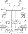
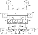
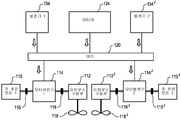
도 1은 가변 동력 수요를 가진 해양 선박에 이용되는 본 발명의 실제적인 하이브리드 추진 및 에너지 분배 시스템의 개략도를 나타낸다.
도 2A는, 최대 연속 추진 부하가 연장된 기간 동안 최대 추진 부하 포텐셜의 약 5% 내지 10%를 초과하지 않는, 느린 수송 및/또는 무-부하 수송뿐만 아니라 선박 비활동 동안 대용량 추진 시스템을 가지는 해양 선박을 작동하기 위한 시스템 작동의 실제적인 최소 방출 모드가 설명된 개략도이다.
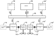
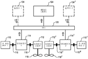
도 2B는 낮은 동력 수요, 최소 방출 모드, 느린 수송 상태에서 추진 및 에너지 관리 시스템의 실제적인 작동을 설명한 개략도를 나타낸다.
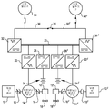
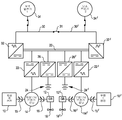
도 3A는, 최대 연속 부하가 연장된 기간 동안 최대 추진 부하 포텐셜의 약 15% 내지 35%를 초과하지 않는, 연속적이며 느린 수송 또는 중간 수송 및 낮은 동력 보조 작동용 용량을 제공하는 시스템 작동의 실제적인 친환경-향해 모드(eco-cruise mode)를 설명하는 개략도를 나타낸다.
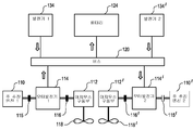
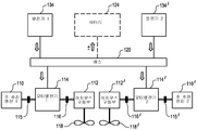
도 3B는 일반적으로 낮은 동력 수요 모드 내지 중간 정도의 동력 수요 모드에서 추진 및 에너지 관리 시스템의 실제적인 작동을 설명한 개략도를 나타낸다.
도 4A는 최대 추진 부하 포텐셜의 약 30% 내지 70%인 상대적으로 넓고 상대적으로 높은 범위 추진 부하 용량을 가지는 시스템 작동의 중간-범위 모드를 설명하는 개략도를 나타낸다.
도 4B는 일반적으로 중간-수준 동력 범위 수요 모드에서 추진 및 에너지 관리 시스템의 실제적인 작동을 설명한 개략도를 나타낸다.
도 5A는 최대 추진 부하 포텐셜의 약 60% 내지 약 100% 또는 그 이상의 부하 용량을 가지는 연속적이며 빠른 수송 및 최대 동력 보조 요건을 위한 고용량 추진 작동을 제공하는 작동의 최대 동력 모드를 설명한 개략도를 나타낸다.
도 5B는 고 부하 용량 추진력을 제공하는 일반적으로 작동의 고부하 수요 모드에서 추진 및 에너지 관리 시스템의 실제적인 작동을 설명한 개략도를 나타낸다.
도 5C는 정격 시스템 동력을 초과하여 추진 부하 수요를 충족시키는 일반적으로 일시적인, 고 부하 수요 작동 모드에서 추진 및 에너지 관리 시스템의 실제적인 작동을 설명한 개략도를 나타낸다.1 shows a schematic diagram of a practical hybrid propulsion and energy distribution system of the present invention for use in marine vessels with variable power demand.
FIG. 2A shows a marine system with a large propulsion system during ship inactivity as well as slow transportation and / or no-load transportation, where the maximum continuous propulsion load does not exceed about 5% to 10% of the maximum propulsion load potential for an extended period of time. A schematic diagram illustrating the actual minimum release mode of system operation for operating a vessel.
2B shows a schematic diagram illustrating the practical operation of the propulsion and energy management system in low power demand, minimal emission mode, and slow transport conditions.
3A illustrates the practical operation of a system operation providing capacity for continuous slow transport or medium transport and low power assisted operation, wherein the maximum continuous load does not exceed about 15% to 35% of the maximum propulsion load potential for an extended period of time. A schematic diagram illustrating the eco-cruise mode is shown.
3B shows a schematic diagram illustrating the actual operation of the propulsion and energy management system in a low to medium power demand mode in general.
4A shows a schematic diagram illustrating a mid-range mode of system operation with a relatively wide and relatively high range propulsion load capacity of about 30% to 70% of the maximum propulsion load potential.
4B shows a schematic diagram illustrating the practical operation of the propulsion and energy management system in general in a mid-level power range demand mode.
5A shows a schematic diagram illustrating the maximum power mode of operation providing a high capacity propulsion operation for continuous and rapid transportation and maximum power assistance requirements having a load capacity of about 60% to about 100% or more of the maximum propulsion load potential.
5B shows a schematic diagram illustrating the actual operation of the propulsion and energy management system in a high load demand mode of operation generally providing high load capacity propulsion.
5C shows a schematic diagram illustrating the actual operation of the propulsion and energy management system in a generally transient, high load demand operating mode that meets the propulsive load demand beyond rated system power.
도 1에서 실제적인 하이브리드 추진 시스템(hybrid propulsion system)이 개략적으로 도시된다. 본 발명인 하이브리드 추진 시스템은 추진력(propulsion)을 위한 에너지를 제공하는 두 개 이상의 소스(source)를 구비하고 가령 디젤 엔진(10 및 10´)(예를 들면, 좌현(port) 및 우현(starboard)에 있는 주 디젤 엔진)과 같은 하나 이상 및 바람직하게는 두 개의 주 추진 엔진 및 하나 이상 및 바람직하게는 두 개의 모터-발전기 유닛(motor-generator unit, 14,14´)을 포함한다. 매우 가변적인 작동 요건 및 성능 요건을 가지는 가령 터그보트(tugboat)와 같은 해양 선박에 특히 이용하기 위해 본 발명인 하이브리드 시스템의 일 실시예에서, 하이브리드 시스템의 드라이브라인(driveline)의 구성(configuration)은 두 개의 주 추진 엔진(10 및 10´)을 구비하며, 이 엔진들 각각은 추진 드라이브라인를 통하여 가령 아지무스 스러스터(azimuth thruster,12, 12')와 같은 기계식 구동 시스템 또는 트랜스미션(transmission)을 통하거나 직접적으로 가령 프로펠러(18, 18')와 같은 추진 출력 부재(propulsive output member)에 결합되며, 추진 드라이브라인 각각은 독립적으로 및 작동적으로 평형 샤프트(parallel shaft)들 상에 제공된다. 아지무스 스러스터는 본 명세서에서 예시일뿐이며, 다른 유형의 기어 박스(gear box) 또는 트랜스미션 시스템이 본 발명의 추진 시스템에 이용될 수 있다는 것이 명백하다. In FIG. 1 a practical hybrid propulsion system is schematically shown. The inventors 'hybrid propulsion system has two or more sources that provide energy for propulsion and, for example, in
비록 본 발명인 하이브리드 추진 시스템이 시스템에 의해 관리된 추진 에너지의 선택적인 소스를 이용하는 제한된 지속 시간의 기간 동안 주 추진 엔진의 정격 출력(rated output)을 초과하여 추진 출력을 구현할 수 있을지라도, 바람직하게는 주 추진 엔진(10, 10')은 시스템을 위해 원하는 최대 추진 부하 포텐셜(maximum propulsive load potential)보다 약간 높게 또는 실질적으로 최대 추진 부하 포텐셜에서 추진 출력을 제공하도록 정해진다. 여러 다른 수준의 추진 출력을 제공하는 여러 다른 유형의 엔진이 여러 다른 해양 선박 적용예에 이용될 수 있다. 약 2000마력 이상의 정격 출력 및 Rolls Royce Z-drive를 가지는 Cummin 사의 주 디젤 엔진의 이용이 높은 추진 부하 용량을 제공하는 터그보트 해양 선박 적용예에 이용되는 예시이다.Although the inventors' hybrid propulsion system can implement propulsion output in excess of the rated output of the main propulsion engine for a limited duration of time using an alternative source of propulsion energy managed by the system. The
전기 모터-발전기(14, 14')(예를 들면, 도 1에 도시된 바와 같이 좌현 및 우현에 있는 MG 유닛)가 각각의 주 추진 엔진 및 이 엔진의 프로펠러(18, 18') 사이에서 샤프트 라인(shaft line)들에 제공된다. 모터 모드에서 작동할 때 및 클러치 매커니즘(clutch mechanism, 16, 16')이 체결될 때, 개별 모터-발전기 유닛은 주 추진 엔진 및 출력 샤프트 포함한 "직렬(in-line)"로 배열되며 개별 출력 샤프트(및 프로펠러)로 추진 동력을 제공할 수 있다. 개별 모터-발전기 유닛도 발전기 모드로 작동할 수 있고 선박 전력 관리 시스템에 전력을 제공할 수 있다. 바람직하게는 모터-발전기들이 짧은 지속 기간 동안 정격 출력 전력을 넘어서 작동할 수 있다. 모터-발전기 유닛들이 가령 AC 농형 유도전동기(squirrel cage induction motor)와 같은 AC 모터로서 제공될 수 있다. 정격 출력 895㎾인 지멘스사(Siemens)의 더블-샤프트 AC 농형 유도전동기(double-shafted AC squirrel cage induction motors)의 이용은 높은 추진 부하 용량을 제공하는 터그보트 해양 선박 적용예에 이용되는 예이다. 다른 유형의 모터 발전기 유닛도 공지되어 있으며 본 발명의 시스템에서 이용될 수 있다.An electric motor-
본 발명의 추진 시스템은 "직렬로"로 배열된 개별 엔진, 모터-발전기, 구동 샤프트 및 프로펠러 조합으로 작동하여, 구동 샤프트 각각, 및 프로펠러 각각,이 단독으로 주 엔진에 의해, 또는 단독으로 모터-발전기 유닛에 의해, 또는 두 개의 소스 모두에 의해 동시에 직접 구동될 수 있다. 개별 샤프트에는 주 엔진이 구동 시스템으로부터 분리되거나 주 샤프트를 돌리게 하는 클러치(15, 15')가 제공될 수 있어, 주 엔진이 정지하거나 전환될때, 모터-발전기(들)가 원동기(prime mover)로서 작동하게 한다. 개별 주 샤프트도 클러치(16, 16')를 가지며, 클러치(16, 16')가 맞물릴 때, 이 클러치에 의해 개별 모터-발전기가 출력 샤프트를 구동하는 모터로써 작동하게 하거나, 클러치가 맞물리지 않았을 때, 이 클러치에 의해 개별 모터-발전기가 출력 샤프트를 구동하지 않고 에너지 분배 시스템에 에너지를 공급하는 발전기로써 작동하게 한다.The propulsion system of the present invention operates with a combination of individual engines, motor-generators, drive shafts and propellers arranged in series, so that each of the drive shafts, and each of the propellers, alone or by the motor alone, It can be driven directly by the generator unit, or by both sources simultaneously. The individual shafts may be provided with
추가적으로 하이브리드 추진 시스템은 에너지 분배 시스템을 구비하며 일반적으로 2개의 버스 장치(dual bus arrangement)를 포함한다. 일반적으로 DC 버스가 선박에 추진력 및 그 외 다른 주요 부하를 포함한 모든 주요 부하를 위한 동력 소스 및 에너지 분배 시스템으로써 제공되며, 바람직하게는 선박의 에너지 저장 용량(energy storage capacity)을 공급할 수 있다. 도 1에 도시된 실시예에서, DC 버스(20)는 DC 버스(20) 및 모터-발전기 유닛(14) 사이에서 양 방향 동력 흐름(bi-directional power flow)을 제공하는 하나 이상의 구동부(22, 22')를 통하여 모터-발전기 유닛(14, 14') 각각에 연결된다. 모터-발전기(14, 14') 각각은 DC 버스(20)에서 에너지를 끌어낼 수 있고 다른 하나와 무관하게 DC 버스(20)로 에너지를 반송할 수 있으며, 대부분 효과적으로 실 시간 기초하여 추진 요건을 충족시킬 수 있다. 일 실시예에서, 구동부(22, 22')는 가변 주파수 구동부(variable frequency drive)를 구비한다. 모터-발전기 및 동력 분배 시스템을 연결하는 가변 주파수 구동부의 이용에 의해 추진 모터 발전기들이 주 구동 엔진의 작동 및 스피드에 무관하게 DC 버스에 전력을 제공하게 한다. 여러 다른 추진 수요하에서 및 언제든지 시스템 필요에 따라서, 주 엔진 및 프로펠러들 사이 샤프트 라인 상에 모터-발전기를 제공하는 것 및 모터-발전기들 및 DC 버스 사이에 가변 주파수 구동부를 제공하는 것에 의해 모터-발전기들이 추진력을 제공하거나 발전기로써 작동하며 DC 버스에 에너지를 공급하게 한다. 추진력 및 다른 요건을 위해 전력이 보조 디젤 발전기(auxiliary diesel generator), 엔진들의 개별 모터-발전기들에 결합된 주 디젤 엔진(Z-Drives와 함께 또는 Z-Drives 없이)에 의해서 또는 이러한 시스템들의 조합에 의해 발생될 수 있다. In addition, the hybrid propulsion system has an energy distribution system and generally includes two dual bus arrangements. In general, a DC bus is provided as a power source and energy distribution system for all major loads, including propulsion and other major loads, to the vessel, preferably supplying the vessel's energy storage capacity. In the embodiment shown in FIG. 1, the
또한 DC 버스는 가령, DC/DC 컨버터(26, 26')들과 같은 적당한 컨버터들을 통하여 가령, 배터리(24, 24')들과 같은 하나 이상의 에너지 저장 시스템에 연결된다. 적당한 Energy Management System (EMS)에 이용될 때, DC/DC 컨버터들에 의해 시스템이 DC 버스에 실질적으로 정전압(constant voltage)을 유지하게 하며, 초과 생성된 용량이 있을 때, DC/DC 컨버터들에 의해 DC 버스에 정전압을 유지하도록 초과 에너지로 배터리(24, 24')를 충전한다. The DC bus is also connected to one or more energy storage systems, such as
DC 버스도 타이브레이커(tiebreaker, 31)에 의해 연결된 가령 하나 이상의 AC 버스(30, 30')와 같은 호텔 부하 분배 시스템(hotel load distribution system)에 동력을 공급하며 연결될 수 있다. 터그보트 해양 선박 적용예의 이용에 적합한 실제적인 일 실시예에서, 각각의 AC 버스는 600V, 3 상 60㎐ 버스를 구비한다. 일반적으로 AC 버스는 시스템의 호텔 부하에 전력을 공급하며, 그 외 다른 보조, 비-추진력 필요를 공급할 수 있다. AC 버스(30, 30')들을 구비한 이 실시예에서, 호텔 부하 분배 시스템은 DC/AC 컨버터(32, 32')에 의해 주 DC 버스에 연결될 수 있다. 컨버터들은 AC 버스 및 DC 버스 사이에서 에너지가 양방향으로 흐르게 하며 예상된 모든 부하를 조성하도록 형성된다. 보조 발전기(34, 34')들이 호텔 부하 요건을 보충하며/또는 추진력, 호텔, 효율 및/또는 방출 요건 지시로써 DC 버스에 에너지를 보충하도록 AC 버스들에 추가적인 에너지를 공급하는 호텔 부하 분배 시스템에 연결될 수 있거나 호텔 부하 분배 시스템에 제공될 수 있다. 실제적인 일 실시예에서, 보조 발전기들이 250KW Tier II 선박 서비스 발전기를 구비할 수 있다.The DC bus may also be connected to and power a hotel load distribution system, such as one or
몇몇 실시예에서, 추가적인 전력 수요도 주 DC 버스에 의해 충족될 수 있다. 본 발명의 하이브리드 추진 및 에너지 관리 시스템을 이용하면, 예를 들면, 가령 선수 및 선미 윈치(bow and stern winch, 28, 28')와 같은 고부하 용량 윈치가 예를 들면, 가령 가변 주파수 구동부들과 같이 예를 들어, 구동부(29, 29')를 통하여 DC 버스로부터 추가적으로 동력을 공급받을 수 있다. 고 전력이 요구되는 그 외 다른 장비도 적당한 컨버터들 또는 구동부들을 통하여 DC 버스로부터 동력을 공급받을 수도 있다고 이해할 수 있다. 몇몇 상황에서, 또한 가령 윈치와 같이 DC 버스로부터 전력을 공급받는 보조 장비의 작동 동안 생성된 재생 에너지(regenerative energy)가 시스템 내 다른 곳에서 에너지 수요를 충족시키기 위해 분배용 DC 버스로 반환될 수 있다. 상대적으로 낮은 전력을 요하는 장비가 DC 버스 또는 AC 버스로부터 동력을 공급받을 수 있다.In some embodiments, additional power demand may also be met by the main DC bus. With the hybrid propulsion and energy management system of the present invention, for example, high load capacity winches such as bow and
가령 선상(on-board) 또는 육지에 기초한 태양광발전 소스(photovoltaic power source), 바람 또는 조류 발전 소스 및 그와 유사한 추가적인 전력 소스가 하이브리드 시스템에 보조 에너지를 제공하도록 이용될 수 있다. 보조 에너지 소스가 AC 및/또는 DC 버스에 전력 공급하도록 결합될 수 있다. 해안 공급 전력(shore power)과 같은 보조 전력 시스템도 추진력 및 보조 부하 모두를 위해 에너지를 제공하기 위해서 본 발명인 하이브리드 추진 및 에너지 관리 시스템에 의해 이용될 수 있다. 해안 공급 전력이 이용가능할 때, 시스템은, 호텔 부하 및 보조 부하용 전력을 제공하기 위해서 및/또는 저장된 에너지 보충하기 위해서 해안 전력을 이용할 수 있고, 육지 옆에 있는(alongside) 동안 디젤 엔진의 작동에 대한 필요가 없으며 선상의 전기 저장 용량에 대한 의존성을 감소시키거나 제거한다. 그리드가 엔진 방출을 감소시키며, 해안 공급 전력이 일반적으로 더욱 효율적으로 생성되며, 해양 선박 주 엔진에 의해 제공된 동력보다 더 낮은 방출을 생성하기 때문에, 그리드(grid)로부터 선상 전력 저장(onboard power storage)의 보충이 일반적으로 바람직하다. 예를 들면, 적절한 DC/DC 컨버터이지만, 해안 공급 전력 변압기(shore power transformer)가 DC 버스에 전력을 공급할 수 있으며 제공될 수 있다.Additional power sources, such as on-board or land based photovoltaic power sources, wind or tidal power sources, and the like may be used to provide auxiliary energy to the hybrid system. Auxiliary energy sources can be combined to power the AC and / or DC bus. Auxiliary power systems such as shore power can also be used by the inventors hybrid propulsion and energy management system to provide energy for both propulsion and auxiliary loads. When coastal power is available, the system may utilize coastal power to provide power for hotel loads and auxiliary loads and / or to replenish stored energy, and to operate diesel engines while ashoreside. There is no need for and reduces or eliminates dependence onboard electrical storage capacity. Onboard power storage from the grid because the grid reduces engine emissions, coastal supply power is generally generated more efficiently, and produces lower emissions than the power provided by the marine vessel main engine. Supplementation is generally preferred. For example, although a suitable DC / DC converter, a coastal power transformer can power the DC bus and can be provided.
바람직하게는 본 발명의 시스템들은 저장 용량을 제공하기 위해서, 낮은 전력 수요를 지원하기 위해서 및 작동 모들들 사이에 일반적으로 짧은 보상 용량(ride-through capacity)을 제공하도록, 가령 배터리와 같은 선상의 재생가능하며 재충전가능한 에너지 저장 시스템들을 포함할 수 있다. 다수의 배터리들이 선택될 수 있지만, 일 실시예에서, 흡수된 글래스 매트 (AGM) 또는 겔 배터리 기술을 채용한 납축전지(lead-acid battery)가 장착된다고 이해된다. 빠른 방전(discharge)/재충전(recharge) 속도 및 비교적 긴 수명을 가질 수 있는, 밀봉되며 유지보수가 필요없는 옵션을 제공하는 납축전지 기술이 다수의 적용예에서 선호된다. 바람직하게는 배터리들은 선박 작동에 의해 영향을 받지 않고 손상되지 않을 선박 위치에 결합된다. 배터리는 선박의 비상 배터리(emergency battery)에 전하를 유지하기 위해 형성될 수 있으며 바람직하게는 에너지 저장 시스템도 주 DC 버스에 에너지를 제공하도록 DC/DC 컨버터와 결합한다. 또한, 가령 니켈 금속 하이브리드(Nickel Metal Hydride)(NiMH) 및 나트륨 니켈 염화물 (Sodium Nickel Chloride)(NaNiCl) 배터리와 같은 선택적인 에너지 저장 옵션이 배터리 저장 및 보충을 위해 장착될 수 있다.Preferably the systems of the present invention are designed to provide low storage capacity, to support low power demands, and to provide generally short ride-through capacity between operating models, for example onboard regeneration such as batteries. It is possible to include rechargeable energy storage systems. Although a number of batteries can be selected, it is understood that in one embodiment, a lead-acid battery employing absorbed glass mat (AGM) or gel battery technology is mounted. Lead acid battery technology, which provides a sealed, maintenance free option that can have a fast discharge / recharge rate and a relatively long life, is preferred in many applications. Preferably the batteries are coupled to a ship position that is not affected by ship operation and will not be damaged. The battery may be formed to maintain charge on the ship's emergency battery and preferably an energy storage system is also combined with the DC / DC converter to provide energy to the main DC bus. In addition, optional energy storage options such as, for example, Nickel Metal Hydride (NiMH) and Sodium Nickel Chloride (NaNiCl) batteries may be equipped for battery storage and replenishment.
이 동력 플랜트 개관은 예시적이며 부품 등급 및 용량뿐만 아니라 부품의 특정 배열(layout) 및 배열이 여러 다른 추진력 수요 및 보조 동력 수요를 공급하도록 수정될 수 있다고 이해된다. 도 1에 도시된 하이브리드 추진 시스템은 이중 엔진(dual engine), 이중 발전기 시스템으로 도시되며, 실질적으로 경상(mirror image)으로 추진 시스템 및 드라이브라인이 한 쌍의 프로펠러들을 구동하도록 제공된다. 단일 또는 다중 프로펠러를 구동하도록, 단일 엔진 및 다중 엔진 시스템이 본 발명의 하이브리드 추진 및 에너지 관리 시스템을 이용하여 작동될 수 있으며 제공될 수 있다고 이해될 수 있다. 또한 하이브리드 추진 시스템이 독립형(stand-alone)으로 새롭게 설치된 시스템으로서 제공될 수 있거나 다양한 부품이 현존하는 추진 시스템을 본 발명인 하이브리드 추진 시스템 및 에너지 관리 시스템으로 전환하도록 새롭게 장착되며 변경할 수 있다고 이해될 수 있다. This power plant overview is illustrative and it is understood that the specific layout and arrangement of the components as well as the component ratings and capacities can be modified to supply several different propulsion demands and auxiliary power demands. The hybrid propulsion system shown in FIG. 1 is shown as a dual engine, dual generator system, provided that the propulsion system and driveline drive a pair of propellers substantially in a mirror image. It will be appreciated that single engine and multiple engine systems can be operated and provided using the hybrid propulsion and energy management systems of the present invention to drive single or multiple propellers. It can also be understood that the hybrid propulsion system may be provided as a stand-alone newly installed system or may be newly installed and modified to convert existing propulsion systems to the hybrid propulsion and energy management systems of the present invention in a variety of components. .
하이브리드 시스템이 현존하는 시스템에 새로이 장착될 때, 추가 AC 전력원이 필요하다면, 현존하는 AC 스위치보드(switchboard)가 유지될 수 있고 추가 AC 스위치보드 내로 통합될 수 있다. 새로 들어온 보조 발전기(auxiliary generator incomer)들, 데크 윈치(deck winch) 및 그 외 다른 고전력이 필요한 부품을 위한 현존 연결부가 주 에너지 관리 DC 버스로 다시-경로(re-routed)를 설정될 수 있고, 이전에 존재한 AC 스위치보드가 예를 들면, 실질적으로 호텔 부하만을 공급하기 위해 배열될 수 있다. 바람직하게는, 데크 윈치(Deck winch)들 및 그 외의 다른 상당한 부하가 DC 버스로부터의 주파수 구동부(frequency drive)에 의해 구동된다. 이로 인해 AC 버스의 안정성이 증가하며 연결된 호텔 부하에 전압 변동(fluctuation)의 충격을 감소시킨다.When a hybrid system is newly mounted in an existing system, existing AC switchboards can be maintained and integrated into additional AC switchboards if additional AC power sources are needed. Existing connections for new auxiliary generator incomers, deck winches and other high power components may be re-routed to the main energy management DC bus, Previously present AC switchboards can be arranged, for example, to supply substantially only hotel loads. Preferably, deck winches and other significant loads are driven by a frequency drive from the DC bus. This increases the stability of the AC bus and reduces the impact of voltage fluctuations on connected hotel loads.
요구된 바와 같이 선박 호텔 부하 및 그 외 다른 AC 부하를 충족시키기 위해, DC 버스와 AC 버스 사이에 연결된 컨버터들에 의해 에너지가 주 DC 버스에서 AC 버스(들)로 흐르게 한다. 또한 모터가 출력 샤프트를 구동하도록 작동하는 작동 모드 동안 샤프트에 동력을 공급하기 위해서, 주 DC 버스에서 추진 모터-발전기 유닛으로 컨버터들 또는 가변 주파수 구동부를 통하여 전력이 제공될 수 있다. 모터-발전기가 발전기 모드에서 작동하는 작동 모드에서, 요구된 바와 같이, 에너지 저장 예비분(energy storage reserve)을 재충전하기 위해서 및 보조 요건을 위한 에너지를 제공하기 위해서 모터에서 주 DC 버스로 에너지가 공급될 수 있다. 보조 발전기들 중 하나 또는 둘 모두가 구동되며 AC 버스에 전력을 공급할 때, 주 DC 버스로부터 제공된 추진력 및 그 외 다른 요건을 위한 전력을 제공하도록, 초과 에너지가 컨버터들을 통하여 AC 버스로부터 DC 버스로 공급될 수 있다.To meet the ship hotel load and other AC loads as required, the energy flows from the main DC bus to the AC bus (es) by converters connected between the DC bus and the AC bus. In addition, power may be provided through converters or variable frequency drives from the main DC bus to the propulsion motor-generator unit in order to power the shaft during the operating mode in which the motor operates to drive the output shaft. In the operating mode in which the motor-generator operates in generator mode, energy is supplied from the motor to the main DC bus to recharge energy storage reserves as required and to provide energy for auxiliary requirements. Can be. When one or both auxiliary generators are driven and power the AC bus, excess energy is supplied from the AC bus to the DC bus through the converters to provide power for the propulsion provided by the main DC bus and other requirements. Can be.
시스템 동력 및 추진력 수요가 변함에 따라, 하이브리드 추진 및 에너지 관리 시스템의 작동이 다수의 소스로부터 넓은 범위의 수요에 따라 충분한 작동을 제공하도록 가변되며 조절된다. 몇몇 제어 및 구현 방식(implementation scheme)에서, 조작자가 시스템의 작동을 통제하는 미리 형성된 일련의 입력 선택 중에서 원하는 작동 변수를 선택할 수 있다. 몇몇 실시예에서, 추진 및 에너지 관리 시스템이 가장 연료 효율적인 방식으로, 가장 낮은 방출 방식으로, 가장 총 에너지-안정된 방식 또는 그와 유사한 방식으로 출력 수요를 충족시키도록, 조작자는 원하는 출력 또는 출력들의 조합을 선택할 수 있다. 하이브리드 추진 및 에너지 관리 시스템의 작동이 미리 결정된 작동 프로토콜에 따라 EMS에 의해 자동으로 모니터링되고 제어될 수 있다. 미리 결정된 작동 모드가 조작자에 의해 선택가능하며 조작자에 제공되거나 조작자에 의해 지정된 원하는 출력 요건에 따라 시스템에 의해 선택된 실시예에서, 몇몇 또는 다수의 작동 모드들이 제공될 수 있다. 선택적인 실시예에서, 시스템 배열, 이용가능한 에너지 소스 및 이와 유사한 것에 따라, EMS가 부품 및 총 시스템 성능 및 에너지와 동력 수요를 모니터링하고, 가장 효율적인 방식으로 하이브리드 추진 및 에너지 관리 시스템이 작동되는, 실질적으로 실시간에 기초하여 선호된 작동 변수를 인식함으로써, 시스템은 실질적으로 연속적인 가변 모드로 작동할 수 있다. As system power and propulsion demands change, the operation of hybrid propulsion and energy management systems is varied and adjusted to provide sufficient operation in accordance with a wide range of demands from multiple sources. In some control and implementation schemes, the operator can select the desired operating variable from a series of preformed input selections that control the operation of the system. In some embodiments, the operator can output the desired output or combination of outputs such that the propulsion and energy management system meets the output demand in the most fuel efficient, lowest emission, most total energy-stable or similar manner. Can be selected. The operation of the hybrid propulsion and energy management system can be automatically monitored and controlled by the EMS according to a predetermined operating protocol. In embodiments where the predetermined operating mode is selectable by the operator and is provided by the operator or selected by the system according to the desired output requirements specified by the operator, several or multiple operating modes may be provided. In an alternative embodiment, the EMS monitors the parts and total system performance and energy and power demands, and the hybrid propulsion and energy management system is operated in the most efficient manner, depending on the system arrangement, available energy sources and the like. By recognizing the preferred operating variables based on real time, the system can operate in a substantially continuous variable mode.
실제적인 작동 모드는 다양한 시스템 및 작동 모드 배열를 이용하여 시스템이 선택할 것 같은 작동 변수 및 예상될 수 있는 시스템의 성능, 연료 경제성 및 방출 감소의 수준을 조작자가 이해하도록 설계된 개념적인 모델의 구성요소라고 여겨질 수 있다. 요구된 부하가 미리 결정된 시간 기간보다 더 길게 작동 모드에서 시스템의 용량을 초과할 때, 제어 시스템은 요구된 전력 생성을 구현하도록 시스템 모드을 자동적으로 증대시킨다. 도 2A 내지 도 5C에 따라, 작동에 대한 다중 개별 모드가 아래에서 설명되며, 이 작동 모드들은 예시적이며 추가적인 또는 여러 다른 작동 모드가 형성되는 것이 가능하며 특정 상황에서 요구된다고 이해된다. 도 2A 내지 도 5C의 개별 도면에서 나타난 특정 부품 배열이 각각의 특정 작동 모드용 예시이며 각각의 모드에서 그 외 다른 배열이 가능하다고 이해된다.The actual operating mode is considered a component of a conceptual model designed to allow the operator to understand the operating variables the system is likely to choose and the level of performance, fuel economy and emission reduction that can be anticipated using the various system and operating mode arrangements. Can lose. When the required load exceeds the capacity of the system in the operating mode longer than a predetermined time period, the control system automatically increases the system mode to achieve the required power generation. According to FIGS. 2A-5C, multiple individual modes of operation are described below, which are understood to be exemplary and that additional or different modes of operation are possible and may be required in certain circumstances. It is understood that the specific component arrangements shown in the individual figures of FIGS. 2A-5C are examples for each particular mode of operation and other arrangements are possible in each mode.
최대 연속 부하가 연장된 기간 동안 최대 추진 부하 포텐셜의 약 5% 내지 10%를 초과하지 않는, 비활동 기간 및 느리거나 무-부하 수송 기간 동안의 선박을 위한 실제적인 최소 방출 모드 작동 개략도가 도 2에 도시된다. 선박이 매우 느린 속도로 이동하며 부하를 형성하지(pull) 않을 때 및 연속적인 부하가 연장된 기간 동안 최대 용량의 약 10%를 초과하지 않을 때, 선박이 고정되며 해안공급 전력을 이용하지 동안, 이 모드는 일반적으로 선박 비활성의 기간 동안 이용될 수 있다. 일반적으로 최소 방출 모드에서 작동은 주 DC 버스 및 추진 요건을 공급하도록 배터리 저장 용량을 단독으로 이용하며, 추가적인 에너지 용량 및 저장을 위해 모터-발전기를 이용한다. 도 2A에 도시된 실제적인 최소 방출 모드 개략도에서, 선상 배터리(24, 24')들에 저장된 에너지가 적합한 컨버터(26, 26')들을 통하여 DC 버스(20)로 공급된다. 호텔 부하 수요를 충족하도록 주 DC 버스(20)가 적합한 컨버터(32, 32')들을 통하여 AC 버스(30, 30')들에 전력을 제공한다. 선행 기술로 공지된 바와 같이, 적합한 공급장치(feeder)/차단기(breaker) 및 연동 매커니즘(interlock mechanism)(들)이 AC 버스 및 DC 버스 상에 제공될 수 있다. 만약 필요하거나 요구된다면, 일반적으로 호텔 부하는 연장된 기간 동안 배터리 소스 단독으로부터 충족될 수 있다.FIG. 2 is a practical minimum emission mode operating schematic for ships during inactive periods and slow or no-load transportation periods where the maximum continuous load does not exceed about 5% to 10% of the maximum propulsion load potential for an extended period of time. Is shown. When the ship moves at very slow speeds and does not pull up and when the continuous load does not exceed about 10% of its maximum capacity for an extended period of time, while the ship is stationary and not using the coastal supply power, This mode can generally be used during periods of vessel inactivity. Operation in minimal emission mode typically uses battery storage alone to provide the main DC bus and propulsion requirements, and motor-generators for additional energy capacity and storage. In the practical minimum emission mode schematic shown in FIG. 2A, the energy stored in the
상기 유형의 최소 방출 작동 모드에서, 주 DC 부스(20)도 비교적 낮은 추진 수요를 충족시키기 위해서, 필요하다면, 모터-발전기 유닛(14, 14')으로 에너지를 제공할 수 있다. 이 배열에서, 모터-발전기 클러치(motor-generator clutch, 16, 16')들이 프로펠러(18, 18')들을 구동하도록 맞물린다. 주 엔진(10, 10')들 중 어느 것도 작동하지 않고 주 엔진 클러치(15, 15')들 중 어느 것도 추진 출력을 구동 샤프트에 제공하기 위해 맞물리지 않는다. 그러나, 주 엔진(10, 10')들은 증가된 추진력 수요가 보류하거나 여러 다른, 비교적 높은 추진력 수요의 작동 모드로 변경되는 출발 준비 상태(ready-to-start condition)로 유지된다. 일반적으로, 에너지를 AC 버스(30, 30')들에 제공하도록 이용가능한 보조 발전기(34, 34')들 중 어느 것도 최소 방출 모드에서 작동되지 않는다. 그러나, 보조 발전기(34, 34') 중 하나 또는 둘 모두는 스위치(35, 35')를 연결함으로써 AC버스(30, 30')들 중 하나 또는 둘 모두에 전력을 제공하도록 이용될 수 있고, 대기 모드(stand-by mode)일 수 있다. 이 작동 모드에서, AC 버스(30, 30')들도, 필요하다면, 추진력을 모터-발전기 유닛(14, 14')에 제공하도록, 컨버터(32, 32')들을 통하여 에너지를 DC버스(20)에 공급할 수 있다.In this type of minimal emission mode of operation, the
낮은 에너지 및 낮은 추진력 수요를 위해서, 일반적으로 최소 방출 모드를 진행되는 것과 같이, 에너지 및 추진력 수요를 충족시키기 위해 저장된 에너지가 충분할 수 있다. 일반적으로, 미리 결정된 최소 배터리 충전 수준이 인식되며 에너지 관리 시스템의 제어 로직(control logic) 내로 통합된다. 최소 배터리 충전 임계점(threshold)에 다다르면, 보조 발전기의 하나 또는 둘 모두는 에너지를 AC 버스에 제공하기 시작한다. 초과 에너지가 AC 버스에서 이용가능한 정도까지, 가령 윈치 전력 수요 및 그와 유사한 것과 같은, 추진력 또는 그 이외에 다른 선박 수요를 충족시키도록, 초과 에너지가 AC 버스에서 DC 버스로 공급된다. 초과 에너지가 DC 버스에서 이용가능한 정도까지, 배터리 전력을 회복하도록, 초과 에너지는 DC 버스에서 에너지 저장 시스템(배터리)로 공급된다. 배터리 전력이 요구되거나 미리 결정된 수준으로 회복될 때까지 또는 호텔 수요가 감소되거나 추진 수요가 감소되거나 이 상황들이 조합될 때, 보조 발전기 중 하나 또는 둘 모두는 비활성화될 수 있다. 주엔진, 모터-발전기 유닛 및 클러치의 직렬 배열이 주엔진의 작동 없이 낮은 추진 수요 상황에서 구동렬(drive train)을 작동하게 하며, 또한 추진 드라이브라인와 무관하게 시스템 내 다른 곳에서 분배 및 이용을 위해 에너지를 제공하는 발전기로써 모터-발전기 유닛을 작동하게 한다. For low energy and low propulsion demands, there may be sufficient energy stored to meet energy and propulsion demands, as is generally the case with minimal emission modes. In general, a predetermined minimum battery charge level is recognized and incorporated into the control logic of the energy management system. When the minimum battery charge threshold is reached, one or both of the auxiliary generators begin to provide energy to the AC bus. To the extent that excess energy is available on the AC bus, the excess energy is supplied from the AC bus to the DC bus to meet propulsion or other vessel demands, such as winch power demand and the like. To the extent that excess energy is available on the DC bus, the excess energy is supplied to the energy storage system (battery) on the DC bus. One or both of the auxiliary generators may be deactivated until battery power is required or restored to a predetermined level, or when hotel demand is reduced, propulsion demand is reduced, or these situations are combined. The serial arrangement of the main engine, motor-generator unit and clutch allows the drive train to operate in low propulsion demand conditions without the main engine running, and also for energy distribution and use elsewhere in the system, independent of the propulsion driveline. Operate the motor-generator unit with a generator that provides.
도 2B는 단일 전기 분배 버스(120)를 가지는 개략적으로 도시된 시스템 내에서 유사한 최소 방출, 낮은 추진력 모드의 작동을 나타낸다. 실선 화살표는 이 작동 모드 동안 에너지 흐름의 방향을 나타낸다. 최소 방출, 낮은 추진력 작동 모드에서, 연속된 화살표로 나타난 바와 같이, 에너지가 원하는 버스 용량을 유지하도록 요구될 때, 에너지는 배터리 뱅크(battery bank, 124)에서 버스(120)로 이동하며, 원하는 버스 용량을 유지하는 에너지를 초과하여 에너지가 이용가능할 때, 에너지는 버스(120)에서 배터리 뱅크(124)로 공급된다. 프로펠러(118 및 118')가 구동 모터 모드에서 작동하는 모터-발전기(114, 114')에 의해 배타적으로 구동되며 발전기 클러치(116, 116')를 맞물리게 함으로써 구동 샤프트에 개별적으로 연결된다. 실선 화살표에 의해 표시된 바와 같이, 구동 모터 모드에서 모터-발전기(114, 114')를 위한 전기 에너지가 버스에 의해 공급된다. 이 작동 모드에서는 엷은 활자체로 나타낸, 주 추진 엔진(110 및 110')이 활성화되지 않고, 주엔진 클러치(115, 115')는 맞물리지 않는다. 필요하다면 호텔 및/또는 추진 요건을 위해 에너지를 버스(120)에 공급하도록(화살표에 의해 표시된 바와 같이), 점선에 의해 나타난 바와 같이, 보조적인 발전기(134, 134')들이 임의로 활성화되며, 간헐적으로 작동될 수 있다.2B shows the operation of a similar minimum emission, low propulsion mode in a system schematically shown having a single
도 3A는 본 발명의 추진 시스템을 도시하며, 이 추진 시스템은 실제적으로 주로 상당히 낮은 추진력 수요 항해 모드에서 작동하며, 이 모드에서 추진 및 에너지 관리 시스템은 연속적이며 느린 이동 및 낮은 동력 보조 활동을 위해 추진력을 제공한다. 일반적으로, 최대 연속 추진 부하가 약 5%이상이며 추진 시스템의 최대 부하 용량의 약 35%를 초과하지 않을 때, 이 작동 모드가 적합하다. 이 작동 모드에서, 일반적으로 DC 버스(20)에 전력을 공급하기 위해 배터리 저장 시스템(24,24')에서 온 에너지가 이용가능하며, 하나 이상 및 바람직하게는 두 개의 보조 발전기(34, 34')가 전력을 적당한 컨버터(32, 32')들을 통하여 AC 버스(30, 30')로 및 DC 버스(20)로 제공하도록 활성화되고 작동된다. DC 버스(20)는 에너지를 모터-발전기 유닛(14, 14')으로 분배하며, 이 유닛들이 맞물린 클러치(16, 16')를 통하여 출력 샤프트 및 프로펠러(18, 18')를 구동시킨다. 낮은 추진력 수요 항해 모드에서 보조 발전기(34, 34')의 작동은 일반적으로 추진 시스템과 호텔의 수요 및 그 이외에 다른 부하 수요에 의해서 및 부품 효율 곡선, 부품 용량 및 전체 시스템의 배열에 의해서 결정된다. 만약 추가적인 추진력이 요구되거나 추가적인 에너지가 호텔 또는 보조 수요를 충족시키기 위해 필요하다면, 일반적으로 에너지는 배터리 저장 및 보조 발전기들로부터 일차적으로 유입되고, 주 엔진들 중 하나가 온라인 된다.FIG. 3A illustrates the propulsion system of the present invention, which actually operates primarily in a significantly low propulsion demand navigation mode, in which the propulsion and energy management systems are driven for continuous, slow movement and low power assist activity. To provide. Generally, this mode of operation is suitable when the maximum continuous propulsion load is at least about 5% and does not exceed about 35% of the maximum load capacity of the propulsion system. In this mode of operation, energy from
일반적으로, 만약 전기 부하 수요 및/또는 추진 부하 수요가 미리 결정된 기간보다 더 길게 보조 발전기의 용량을 초과한다면, EMS가 에너지 요건을 충족시키기 위해서 및 필요한 전력 생성을 구현하기 위해서, 주 엔진(10, 10')들 중 하나 이상에서 움직이기 시작한다. 도 3A에 도시된 작동 배열은 주엔진뿐만 아니라 보조 발전기(34 및 34')의 작동을 포함하며, 이 배열은 맞물린 클러치(15)에 의해 추진력을 드라이브라인 및 프로펠러(18)에 제공한다. 일반적으로 낮은 추진 수요 항해 모드는 단일 주엔진의 활성화를 요한다. 그리고, 일반적으로 고 효율, 고 출력 상태에서 엔진 작동은 추진력을 제공하고 모터 발전기(14)를 통하여 주 에너지 분배 버스(20)로 반환되는 초과적인 에너지 생성을 제공한다. 버스(20)로 제공된 초과 에너지는 에너지 저장 시스템을 보충하도록, 그리고 하기된 바와 같이, 추진력을 반대편 출력 샤프트에 제공하도록 보조 전력 수요를 이용할 수 있다.In general, if electrical load demand and / or propulsion load demand exceeds the capacity of the auxiliary generator for longer than a predetermined period of time, in order for the EMS to meet energy requirements and to implement the required power generation, the
바람직하게는 본 발명인 하이브리드 추진 및 에너지 관리 시스템 배열에 의해 단일 주엔진이 효과적으로 두 개의 추진 출력 샤프트를 구동하게 한다. 도 3B에도시된 실제적인 실시예에서, 주엔진(110)은 주엔진의 출력 샤스트 상에 아지무스 구동부(azimuth drive, 112) 및 프로펠러(118)를 직접적으로 구동시키도록 일반적으로 고효율, 고출력 모드에서 작동한다. 본 실시예에서, 또한 주엔진(110)은 (화살표에 의해 나타난 바와 같이)에너지를 DC 버스(120)에 공급하도록 발전기 모드에서 모터-발전기(114)를 구동시키며, 교대로 이 DC 버스는 (화살표에 의해 나타난 바와 같이)에너지를 모터/발전기(114')에 공급하며, 그 이외 다른 구동 샤프트 상에 아지무스 구동부(112') 및 프로펠러(118')를 구동시키도록 구동 모드에서 작동한다. 이 배열에서, 또한 보조 발전기(134, 134')가 (화살표에 의해 나타난 바와 같이)에너지를 버스(120)에 제공하기 위해 작동된다.Preferably the hybrid propulsion and energy management system arrangement of the present invention allows a single main engine to effectively drive two propulsion output shafts. In the practical embodiment shown in FIG. 3B, the
이로써, 도 3B에 도시된 비교적 낮은 추진력 수요 배열에서, 하나의 주 엔진 및 두 개의 보조 발전기가 추진력 및 호텔 및 보조 동력 수요를 공급하도록 이용가능하다. 이 배열에 의해 두 개의 주엔진 모두가 추진력을 위해 요구되는 시간의 양을 감소시키며, 고 부하 범위에서 더 효율적으로 작동하는 주엔진이, 다른 방법으로 주 엔진/주 엔진들이 작동하는 것보다 더 효과적으로 구동되게 한다. 버스(120)에 초과 에너지가 배터리 저장 시스템(124)으로 공급되며, 이는 일반적으로 충전 상태이다. 제어기가 엔진 및 선박의 수명 동안 이 모드에서 최초 응답기(primary responder)로써 지정된 주엔진을 교번적으로 바꾸도록 프로그램화될 수 있다. 그 외 다른 작동 모드와 마찬가지로, 배터리 저장 시스템에 의해 일시적인 수요에 대한 일시적인 보상이 제공될 수 있다. Thus, in the relatively low propulsion demand arrangement shown in FIG. 3B, one main engine and two auxiliary generators are available to supply propulsion and hotel and auxiliary power demand. This arrangement reduces the amount of time both main engines require for propulsion, and a main engine that operates more efficiently at high load ranges is more effective than other main engines / main engines operating in other ways. To be driven. Excess energy is supplied to the
중간-정도 추진 수요 작동 모드가 도 4A에서 개략적으로 도시된다. 일반적으로 이 작동 모드는 연속적인 수송 및 높은 페센트의 선박 보조 예정 계획(scenario)을 위해 충분한 추진 부하 용량을 제공하며, 이 예정 계획에서는 최대 추진 부하 요구가 연장된 기간 동안 총 부하 용량의 약 30% 내지 70%를 초과하지 않는다. 이 작동 모드에서, 연속적이거나 간헐적으로 일반적으로 고효율 및 고출력으로 추진력, 호텔 및 보조 부하 요건을 충족시키기 위해서, 하나 이상 및 일반적으로 두 개의 주엔진이 작동된다. 호텔 및 보조 부하 요구를 충족하기 위해서 및 적절하게 배터리를 충전하기 위해서 초과 에너지가 주 전기 분배 버스에 공급된다. 보조 발전기들 중 하나 또는 두 개 모두 및 배터리 저장소는 이 모드에서 보조 전력 생성을 위해 이용가능하다.The medium-degree propulsion demand operating mode is shown schematically in FIG. 4A. In general, this mode of operation provides sufficient propulsion load capacity for continuous transport and high percentages of vessel-assisted ship scenarios, where approximately 30 percent of the total load capacity for extended periods of maximum propulsion load demand is extended. It does not exceed% to 70%. In this mode of operation, one or more and generally two main engines are operated to meet propulsion, hotel and auxiliary load requirements, typically at high efficiency and high power, continuously or intermittently. Excess energy is supplied to the main electrical distribution bus to meet hotel and auxiliary load needs and to properly charge the battery. One or both of the auxiliary generators and the battery reservoir are available for auxiliary power generation in this mode.
도 4A에서 도시된 바와 같이, 추진력은 고효율 작동과 일치되게 일반적으로 고출력으로 작동한다. 두 개의 주엔진(10, 10') 모두는 맞물린 클러치(15, 15', 16 및 16')를 통하여 아지무스 구동부(12, 12') 및 프로펠러(18, 18')에 동력을 제공하도록 이용된다. 본 모드에서 고출력으로 작동될 때, 발전기 모드에서 주엔진(10, 10')은 일반적으로 추진 수요를 위해 요구된 출력을 초과하여 출력을 생성하며, 또한 에너지가 호텔 부하 수요, 가령 윈치 수요와 같은 보조 부하 수요를 충족시키는 분배 및 이용을 위해 버스(20)에 제공되는, 발전기 모드에서 모터/발전기(14, 14')를 구동시키도록 그리고 배터리를 충전시키도록 에너지를 제공한다. 주엔진이 추진 및 보조 수요 모두를 충족시키는 출력을 제공하기 때문에, 일반적으로 보조 발전기(34, 34')는 상기 모드에서 활성화되지 않는다. As shown in FIG. 4A, the propulsion force generally operates at high power, consistent with high efficiency operation. Both
만약 중간-정도 추진 모드에서 동시에 주 엔진 둘 모두의 작동에 의해 제공된 추진력 및 에너지가 추진력, 호텔, 보조 및 에너지 저장 수요의 출력을 초과한다면, 도 3B에 도시된 바와 같이 간헐적인 기간 동안 주엔진들 중 하나가 비활성화될 수 있고, 이 시스템이 실질적으로 작동될 수 있다. 에너지가 배터리 저장소로부터 주 버스로 공급될 수 있으며 감소된 주엔진 작동의 기간 동안 요구된 바와 같이 분배될 수 있다. 상기한 바와 같이, 시스템의 융통성(flexibility)에 의해 단일 주엔진이 추진 드라이브라인들 모두를 구동시키도록 이용될 수 있고 배터리 저장소는 일시적인 수요의 일시적인 보상을 제공할 수 있다. 두 개의 주 엔진이 구동되는 동안, 이 배열은 시스템의 효율을 증가시키고, 두 개의 엔진들이 구동되는 시간의 양을 일반적으로 감소시키며, 엔진의 부하를 최선의 범위로 증가시킴으로써 작동하는 엔진의 효율성을 증가시킨다. 배터리 예비분이 낮을 때, 추진력, 호텔 또는 보조 수요가 증가되며, 주 엔진들 둘 모두가 계속되는 수요를 충족을 충족하기 위해 제공되도록 및 배터리 저장을 보충하도록 작동될 수 있다. 비록 조작자가 선박의 성능 및 유지 부수 계획을 최적화하도록 엔진 취급을 관리하게 하기 위해서, 수동 제어가 제공될 수 있을지라도, 제어기가 엔진 및 선박의 수명 동안 이 모드에서 최초 응답기로써 지정된 주엔진을 교번적으로 바꾸도록 프로그램화될 수 있다.If the propulsion and energy provided by the operation of both main engines simultaneously in the medium-degree propulsion mode exceeds the outputs of the propulsion, hotel, auxiliary and energy storage demands, the main engines for intermittent periods as shown in FIG. 3B. One of the can be deactivated and the system can be operated substantially. Energy may be supplied from the battery reservoir to the main bus and distributed as required during the period of reduced main engine operation. As noted above, the flexibility of the system allows a single main engine to be used to drive all of the propulsion drivelines and the battery reservoir can provide temporary compensation for temporary demand. While the two main engines are running, this arrangement increases the efficiency of the system, generally reduces the amount of time the two engines are running, and increases the efficiency of the engine operating by increasing the load of the engine to the best range. Increase. When the battery reserve is low, propulsion, hotel or auxiliary demand is increased, and both main engines can be operated to provide for meeting the continuing demand and to replenish battery storage. Although manual control may be provided to allow the operator to manage engine handling to optimize the ship's performance and maintenance incident planning, the controller alternates between the main engine designated as the first responder in this mode for the life of the engine and ship. Can be programmed to change
유사한 중간-정도 추진 요구 작동 모드가 단일 전기 분배 버스(120)를 가지는 것으로 개략적으로 나타내진 시스템에서 도 4B에서 개략적으로 도시된다. 실선 화살표는 이 작동 모드 동안 에너지 흐름에 대한 방향을 나타낸다. 주 엔진(110, 110')들에 의해 추진력이 적합한 클러치 장치를 통하여 구동 샤프트, 아지무스 구동부(112, 112') 및 프로펠러(118, 118')에 제공된다. 또한 주 엔진(110, 110')이 발전기 모드에서 모터-발전기(114, 114')를 작동시키도록 에너지를 제공함으로써, 주 엔진들은 적합하게 호텔 및 보조 부하를 충족시키기 위해서 및 배터리 뱅크(battery bank, 124)를 충전하기 위해서 에너지를 공급한다. 보조 발전기(134, 134')들 중 한 개 또는 두 개 모두는 상대적으로 높은 요구 순간 호텔 또는 보조 부하을 충족시키기 위해서 또는 더 신속하거나 더 완전하게 에너지 저장 시스템을 충전하기 위해서, 추가 에너지를 버스(120)에 제공하도록, 점선에 의해 표시된 바와 같이, 상기 모드에서 순간적으로 작동할 수 있다.A similar medium-degree propulsion demand operating mode is shown schematically in FIG. 4B in a system schematically shown having a single
도 5A는 본 발명인 추진 및 에너지 관리 시스템의 총 전력 작동 모드를 개략적으로 나타내며, 이 모드 내에서 추진 시스템은 주 엔진의 정격 추진 부하 용량의 실질적으로 90% 또는 그 이상으로 작동한다. 예를 들면, 크고, 긴 기간의 부하가 연속적이고 빠른 수송 및/또는 총 전력 배 보조 수요가 예상되는 것이 예견될 때, 이 작동 모드가 이용된다. 이 모드로 인해 보조 전력 소스를 제공하고 이용가능한 전력을 효과적으로 관리함으로써, 시스템이 상대적으로 높은 용량인 주 엔진을 통합한 비-하이브리드 추진 시스템의 성능 용량을 충족하게 하거나 초과하게 한다. 추진 수요가 주 엔진 부하 용량의 100%가 아닐 때, 이 모드에서, 전력이 샤프트 라인에서 모터-발전기에 의해 생성될 수 있다. 이 초과 전력이 에너지 저장 시스템을 충전하도록, DC 버스로 공급될 수 있고 호텔 및 보조 전력 수요를 위해 이용될 수 있다. 전체 작동 모드에서, 모든 장비 작동을 이용하여, 시스템은 동일한 출력 용량을 가진 주 엔진을 통합한 비-하이브리드 시스템에서 이용가능한 동력보다 더 많은 동력이 구동부에 가해지도록 하는 기능을 가질 수 있다. 이로 인해 더 신속한 시스템 응답을 제공하는 수단으로써 이용될 수 있거나, 드라이브라인이 추가 토크를 처리할 수 있다면, 선박의 정격 마력(rated horsepower)을 증가시키는 것이 가능하다. 짧은 기간 동안 증가된 출력이 제공될 수 있다. 5A schematically illustrates the total power mode of operation of the inventors propulsion and energy management system, within which the propulsion system operates at substantially 90% or more of the rated propulsion load capacity of the main engine. For example, this mode of operation is used when large, long duration loads are expected to be expected for continuous and rapid transportation and / or total power distribution assistance demands. This mode provides a secondary power source and effectively manages the available power, allowing the system to meet or exceed the performance capacity of a non-hybrid propulsion system incorporating a relatively high capacity main engine. In this mode, power can be generated by the motor-generator in the shaft line when the propulsion demand is not 100% of the main engine load capacity. This excess power can be supplied to the DC bus to charge the energy storage system and used for hotel and auxiliary power needs. In all modes of operation, using all machine operation, the system can have the ability to apply more power to the drive than is available in a non-hybrid system incorporating a main engine with the same output capacity. This makes it possible to increase the ship's rated horsepower if it can be used as a means of providing faster system response, or if the driveline can handle additional torque. Increased output may be provided for a short period of time.
도 5A에 도시된 바와 같이, 고 효율, 고 출력으로 작동하고 개별적으로 체결된 클러치를 통하여 프로펠러(18, 18')로 추진력을 제공하는 주 엔진(10, 10')에 의해 일반적으로 전체 전력 작동 모드에서, 추진력이 제공된다. 추진 및 에너지 관리 시스템이 전체 전력 모드에서 작동할 때, 출력 샤프트 드라이브라인 상에 제공된 모터-발전기 유닛(14, 14')은 주 엔진들에 의해 생성된 초과 에너지를 주 에너지 분배 버스(20)로 공급하는 발전기로써 또는 추가적인 추진 구동력을 출력 샤프트에 공급하는 주 에너지 분배 버스(20)에서부터 에너지를 끌어내는 모터들로써 작동하도록 이용할 수 있다. 추진 모터 모드에서 작동될 때, 모터-발전기는 배터리 및/또는 보조 발전기 전력에 대한 임의의 조합에 의해 버스에 공급된 에너지를 이용하여 개별 컨버터들을 관통하여 DC 버스에 의해 작동된다. 일반적으로 보조 발전기(34, 34') 둘 모두는 AC 버스(30, 30')를 통하여 주 분배 DC 버스(20) 및 개별 컨버터(32, 32')들에 에너지를 제공하는 상기 모드에서 작동된다.As shown in FIG. 5A, generally full power operation by the
일부의 전체 전력 모드에서, 추진력이 공통 샤프트에 출력을 제공하는 추진력 소스를 이용하여 모터로써 작동하는 모터-발전기 유닛과 주 엔진에 모두에 의해 제공된다. 호텔 부하, 모터/발전기 수요 및 임의의 보조 수요를 충족시키기 위해 요구된 에너지를 초과하여 에너지 분배 버스(20)에 공급된 임의의 에너지는 에너지 저장 시스템(배터리들, 24, 24')으로 반송된다. 일반적으로 주 엔진들, 모터 발전기 유닛 및 보조 발전기들이 전체 전력 작동 모드 동안 모든 예상된 추진력 요건, 호텔 부하 및 보조 에너지 요건을 공급하도록 충분한 정격 전력을 가진다.In some full power modes, propulsion is provided by both the motor-generator unit and the main engine, which operate as a motor using a propulsion source that provides output to the common shaft. Any energy supplied to the
두 개의 서로 다른 전체 전력 작동 모드가 단일 전기 분배 버스(120)를 가지는 시스템 내에서 도 5B 및 5C에서 개략적으로 도시되며, 이 시스템 내에서 실선 화살표는 작동 동안 에너지 흐름에 대한 방향을 나타낸다. 도 5B에 도시된 전체 전력 작동 모드에서, 주 엔진(110, 110')들 둘 모두는 적당한 클러치 매커니즘을 통하여 아지무스 구동부(112, 112') 및 프로펠러(118, 118')로 전체 전력 출력을 제공한다. 보조 발전기(134, 134') 모두는 주 에너지 분배 버스(120)에 에너지를 제공하도록 작동된다. 모터-발전기 유닛(114, 114') 둘 모두는 주 엔진들과 함께 직렬로 모터 구동 모드에서 작동되며, 추진력을 개별 출력 샤프트에 제공하도록 버스(120)로부터 에너지를 끌어낸다. 추진 수요가 주 엔진 및 모터-발전기의 총 부하 용량보다 낮을 때, 이 배열이 이용될 수 있고, 일반적으로 이 배열은 에너지 저장 시스템(예를 들면, 배터리 뱅크, 124)으로 주 버스(120) 상에 이용가능한 초과 에너지를 반송하며, 이는 충전 모드에서 작동한다.Two different full power modes of operation are shown schematically in FIGS. 5B and 5C in a system having a single
도 5C는 추진 수요가 주 엔진 및 모터-발전기의 총 부하 용량보다 더 높을 때, 일반적으로 일시적이게 이용될 수 있는 또 다른 전체 전력 작동 모드를 나타낸다. 본 실시예에서, 주 엔진(110,110')들 두 개 모두는 적당한 클러치 매커니즘을 통하여 아지무스 구동부(112,112') 및 프로펠러(118, 118')들에 전체 전력 출력을 제공한다. 보조 발전기(134, 134') 두 개 모두는 주 에너지 분배 버스(120)로 에너지를 제공하도록 작동된다. 두 개의 모터-발전기 유닛(114, 114') 모두가 주 엔진와 직렬로 모터 구동 모드 인라인에서 작동되며 추진력을 개별 출력 샤프트로 전달하도록 버스(120)로부터 에너지를 끌어낸다. 추가적으로 일시적인 기간 동안 추진력을 위해 정격된 전력을 초과하여 추진력을 제공하도록 또는 보조 또는 호텔 부하를 충족시키도록, 배터리 에너지가 버스(120)로 제공된다. 배터리 뱅크가 줄어들거나 소진될 때까지 작동에 대한 상기 모드만이 유지될 수 있다. 일반적으로, 용량 작동 모드를 걸친 이 모드는 단지 간헐적으로만 이용되거나 일시적인 고 전력 요건을 충족시키기 위해 이용된다.5C shows another full power mode of operation that can be used temporarily, generally, when the propulsion demand is higher than the total load capacity of the main engine and motor-generator. In this embodiment, both
상기 설명된 바와 같이, 에너지 관리 시스템(Energy Management System)(EMS)은 다수의 소스로부터 가변적인 에너지 요건을 충족시키는 동시에, 효율적인 방식으로 시스템을 도처에 다양한 추진 소스를 작동하고 에너지를 분배하도록, 추진 시스템, 에너지 분배 시스템 및 에너지 저장 시스템의 작동에 대한 많은 측면을 제어한다. EMS는 일반적으로, 조작자가 복수의 미리 결정된 작동 모드 중에서부터 선택하게 할 수 있는, 조작자 인터페이스 및 다양한 부품 출력, 용량들, 현재 작동 변수 및 상태, 에너지 레벨 등의 입력을 EMS로 제공하는 센서들, 발전기 및 시스템 보호 시스템, 시스템 유지 유틸리티, 시스템 경고 및 알림 유틸리티 및 그 와 유사한 것을 포함한 비교적 더 큰 작동 시스템의 부분으로 형성될 수 있거나 다수의 기능을 포함할 수 있다. 일반적으로 상기 설명된 바와 같이, EMS는 작동 상태 및 주 엔진(들), 모터-발전기 유닛(들), 드라이브라인 및 그 이외 다른 클러치들, 보조 발전기(들), 배터리 저장 시스템의 출력을 작동시키고 변화시킴으로써 하이브리드 추진 시스템을 통하여 부하 요구에 부합한다. 몇몇 실시예에서, 작동 시스템에 의해 조작자가 가령 드라이브라인 rpm 및/또는 토크, 순간 스피드 및/또는 지속시간(duration), 부하 요건 및/또는 부하 지속 시간 또는 그와 유사한 것과 같은 특정 작동 변수를 선택할 수 있게 하고, 전체 제어 시스템에 의해 적합한 작동 모드를 나타내며 실행하도록 이용된다.As described above, Energy Management System (EMS) propels the system to operate and distribute energy to various propulsion sources everywhere in an efficient manner while meeting variable energy requirements from multiple sources. Control many aspects of the operation of the system, energy distribution system and energy storage system. The EMS generally includes sensors that provide the EMS with inputs for the operator interface and various component outputs, capacities, current operating variables and status, energy levels, etc., which allow the operator to select from among a plurality of predetermined operating modes, It may be formed as part of a relatively larger operating system, including generator and system protection systems, system maintenance utilities, system alert and notification utilities, and the like, or may include multiple functions. In general, as described above, the EMS operates the state of operation and the output of the main engine (s), motor-generator unit (s), driveline and other clutches, auxiliary generator (s), battery storage system and By changing, it meets the load demand through the hybrid propulsion system. In some embodiments, the operating system allows the operator to select specific operating variables such as, for example, driveline rpm and / or torque, instantaneous speed and / or duration, load requirements and / or load duration or the like. And use it to represent and execute a suitable mode of operation by the entire control system.
추진 및 EMS 시스템(들)을 이용한 조작자 인터페이스는 전자 모니터를 구비할 수 있으며, 이 전자 모니터로 인해 조작자가 추진 및 에너지 관리 시스템의 작동 및 제어를 검증 및 감시하게 한다. 작동 모드는 조작자에 의해 선택될 수 있거나 자동적으로 실행된다. 다수의 개별 작동 모드가 제공될 수 있고 프로그램화될 수 있다. 가령, 전자 가속기 페달(electronic accelerator pedal), 조이스틱들 및 레버와 같은 조작자 제어 장치가 조작자 입력을 위해 제공될 수 있고 추진 및 에너지 관리 시스템에 결합될 수 있다. 조작자는 가령 전자 레버 도는 조이스틱과 같은 입력 장치에 의해 추진력을 제어하는 옵션(option)을 가질 수 있거나 조작자는 다수의 미리 선택된 입력을 제공하거나 조작자가 요구된 입력을 지정하게 하는 인터페이스를 통하여 추진 에너지 관리를 제어할 수 있는 옵션을 가질 수 있다. 예를 들면, 모니터 또는 터치 스크린상에 표시된 변수 및 경보 또는 경고를 작동하는 시스템을 이용하여 비-기술 인력을 위한 단순한 작동 플랫폼이 제공될 수 있다. 또한 이 시스템은 더 상세한 유지보수 및 정보 접근/관리를 위한 인터페이스를 제공할 수 있고 모든 기계 장치 모니터링을 단일 플랫폼에 조합할 수 있다. 선택적으로 터치 스크린, 다양한 명령 성분 및 개별 제어를 통합한 표시장치(display)가 가령 주 조타실(wheelhouse) 콘솔과 같은 단일 부품 내로 통할 될 수 있다.The operator interface using the propulsion and EMS system (s) can be equipped with an electronic monitor, which allows the operator to verify and monitor the operation and control of the propulsion and energy management system. The operating mode can be selected by the operator or executed automatically. Multiple individual modes of operation can be provided and programmed. For example, operator control devices such as electronic accelerator pedals, joysticks and levers can be provided for operator input and can be coupled to propulsion and energy management systems. The operator may have an option to control the propulsion by an input device such as an electronic lever or joystick, or the operator may provide a number of preselected inputs or manage the propulsion energy through an interface that allows the operator to specify the required inputs. You can have the option to control. For example, a simple operating platform for non-technical personnel may be provided using a system that operates on variables or alarms or warnings displayed on a monitor or touch screen. In addition, the system can provide an interface for more detailed maintenance and information access / management and combine all mechanical monitoring into a single platform. Optionally, a display that incorporates a touch screen, various command components, and individual controls can be integrated into a single component, such as a main wheelhouse console.
임의로 정해진 시간에 작동하는 엔진 및 발전기의 수는 가령 호텔 및 보조 장비 요건과 같은 추진 시스템 및 보조 부하의 수요에 의해 결정된다. 이 부하가 미리 결정된 기간보다 더 길게 임의의 특정 작동 모드에서 작동하는 엔진 및/또는 발전기의 용량을 초과한다면, 에너지 관리 시스템은 필요한 동력 발전을 제공하기 위해 시스템 작동 모드를 자동적으로 증감시키고 적합한 추가 엔진(들), 모터-발전기(들), 보조 발전기(들) 또는 그와 유사한 것을 활성화시킨다. 시스템의 제어는 EMS을 통하여 부분적으로 또는 완전히 자동화된 방식 또는 수동으로 제공될 수 있다. EMS는 시스템 내부에서 다양한 에너지 소스로부터 이용가능한 출력, 작동 상태 및 에너지 레벨을 감시하고, 시스템의 추진 및 보조 동력 필요(need)를 결정하고 엔진, 보조 발전기들, 모터 발전기 유닛의 작동을 제어하며, 더 점진적으로 부하 및 동력 요건을 충족시키기 위해서 시스템을 도처에 에너지 흐름을 제어할 수 있다. 순간적인 요구에 대한 일시적인 순간보상이 에너지 저장 시스템에 의해 제공될 수 있다.The number of engines and generators operating at any given time is determined by the demand for propulsion systems and auxiliary loads, such as hotel and auxiliary equipment requirements. If this load exceeds the capacity of an engine and / or generator operating in any particular operating mode longer than a predetermined period of time, the energy management system will automatically increase or decrease the system operating mode to provide the required power generation (S), motor-generator (s), auxiliary generator (s) or the like. Control of the system can be provided manually or in partly or fully automated manner via EMS. EMS monitors the power, operating status and energy levels available from various energy sources within the system, determines the propulsion and auxiliary power needs of the system, controls the operation of engines, auxiliary generators, motor generator units, More gradually, the system can control energy flows to meet load and power requirements. Temporary instant compensation for instant needs may be provided by the energy storage system.
본 발명인 몇몇 자동화된 제어 시스템에서, 시스템 작동 모드가 실시간으로 및 실질적으로 연속적인 시간에 기초하여 다양한 시스템 요구에 따라 선택될 수 있고 조절될 수 있고, EMS에 의해 제어되거나 제한된다. 몇몇 작동 모드가 이전에 상세하게 설명되었고, 추가적인 작동 모드가 제공될 것이다. 실제적으로, 동력 요건 및 이용가능한 동력 공급원에 의해 상기와 같이 선박 및 EMS의 작동은 미리 결정된 작동 모드에 따라 자동화될 수 있고 작동될 수 있거나 미리 결정된 다양한 작동 모드가 선박의 현재 또는 예상된 작동 요건을 충족시키기 위해 조작자에 의해 선택될 수 있다. 상기 설명된 바와 같이, 조작자가 미리-프로그램화된 작동 모드를 선택하게 하도록 개별 패널에서 별개의 제어가 제공될 수 있다. 일 실시예에서, 조작자는 선박의 현재 또는 예상 작동 요건을 위해 가장 실용적인 모드를 선택할 수 있다. 선택된 모드에서 유지된 이용가능한 동력을 넘어 스로틀 진행(Throttle advance)이 다음 작동 레벨 또는 모드로 자동화된 진행을 시작할 수 있거나, 긍정 응답(positive response)을 요구하는 신호 및 경고를 실행할 수 있다. 또 다른 실시예에서, 선박이 필요한 부하 또는 출력보다 더 큰 동력을 제공하는 모드에서 미리 결정된 시간 기간이상 동안 작동한다면, EMS는 더 효율적인 모드에서의 작동이 이용가능하다고 표시된 지시 또는 신호를 조작자에게 제공한다. 일반적으로, 자동화된 모드 선택이 몇몇 상황하에서 제공될 수 있거나 작동 불이행(default operation)일 수 있을지라도, 조작자는 모드 선택을 우선할 수 있는 능력을 가진다.In some automated control systems of the present invention, system operating modes can be selected and adjusted according to various system requirements in real time and based on substantially continuous time, controlled or restricted by EMS. Several modes of operation have been described in detail previously, and additional modes of operation will be provided. In practice, the operation of the vessel and the EMS as described above, by virtue of the power requirements and available power sources, can be automated and can be operated according to a predetermined operating mode or the various predetermined operating modes can be applied to the vessel's current or anticipated operating requirements. Can be selected by the operator to meet. As described above, separate controls may be provided on individual panels to allow the operator to select a pre-programmed mode of operation. In one embodiment, the operator can select the most practical mode for the vessel's current or anticipated operational requirements. Throttle advance beyond the available power maintained in the selected mode may begin automated progression to the next operating level or mode, or may trigger signals and warnings that require a positive response. In another embodiment, if the vessel is operating for more than a predetermined time period in a mode that provides greater power than the required load or output, the EMS provides the operator with an indication or signal indicating that operation in a more efficient mode is available. do. In general, even though automated mode selection may be provided under some circumstances or may be a default operation, the operator has the ability to override mode selection.
상기 설명된 바와 같이 전력 모드에서 하이브리드 추진 시스템을 작동하는 기능에 추가하여, 몇몇 실시예에서는, 특정 전력 모드를 선택할 수 있는 EMS의 기능이 조작자 또는 준비에 대한 다중 상태 중 하나에 대한 시스템의 선택에 의해 제한될 수 있다. 준비 상태(readiness state)가 배터리 전력이 작동 동안 어떻게 할당되는지를 결정하도록 EMS에 의해 자동적으로 적용될 수 있거나 조작자에 의해 선택될 수 있다. "수송", "보조" 및 "배터리 회복" 전력 모드에 대한 제공이 예시된다. 수송 및 보조 모드가 선택가능한 제어 특징에 의하여 조작자에 의해 선택가능할 수 있다. 배터리 회복 상태는, 이용가능한 배터리 전력이 미리 결정된 최소 한도 아래로 내려가거나 배터리가 방전되거나 과열될 때 자동적으로 부과될 수 있거나 상태들 하에서 선택될 수 있는, 전체 전력에 대한 제한이다. 상기 방식에서, 하이브리드 시스템은 (예를 들면)선박-보조 작동 동안 주 엔진의 운행중단(shutting down)를 방지할 수 있거나 초과 전력 이용에 의해 고갈된 저장 배터리의 과도한 스트레스(over-stressing)를 방지할 수 있다.In addition to the ability to operate the hybrid propulsion system in a power mode as described above, in some embodiments, the ability of the EMS to select a particular power mode is dependent upon the selection of the system for one of multiple states for the operator or ready. May be limited. The readiness state may be automatically applied by the EMS or selected by the operator to determine how battery power is allocated during operation. The provisions for "transport", "secondary" and "battery recovery" power modes are illustrated. Transport and assistance modes may be selectable by the operator by selectable control features. The battery recovery state is a limitation on the total power that the available battery power can fall under a predetermined minimum limit or can be automatically charged when the battery is discharged or overheated or selected under conditions. In this manner, the hybrid system can prevent shutting down of the main engine during (eg) ship-assisted operation or prevent over-stressing of the storage battery depleted by excess power usage. can do.
일반적으로, 충분한 저장 용량(reserve capacity)이 선호적으로 유지되며 짧은 격발(burst)을 위해 전체 부하의 약 70%로 즉각적인 전기 추진 전력을 제공하도록 이용될 수 있다. 추가적인 생성 용량이 가동되는 동안 이로 인해 작동 모드 사이에서 지연(delay)을 감소시킨다. 가령 65% 전력과 같이 미리 결정된 전력 수준을 넘어서 지속된 진행이 두 개의 주 엔진들 모두 또는 두 개의 엔진들 중 하나를 자동적으로 움직이도록 프로그램화될 수 있다. 이 경우에, 소규모 지연이 발생될 수 있다. 이러한 지연이 허용되지 않는 상태에서, 전체 모드 작동이 사전에 선택될 수 있다.In general, sufficient reserve capacity is preferably maintained and can be used to provide instant electrical propulsion power at about 70% of the total load for short bursts. This reduces the delay between modes of operation while the additional generating capacity is running. Sustained progression over a predetermined power level, such as for example 65% power, can be programmed to automatically move both main engines or one of the two engines. In this case, small delays may occur. In the absence of such a delay, full mode operation may be preselected.
또한, 하나 이상의 선택가능하거나, 프로그램가능하거나 프로그램화된 방출 제어 특성이 제공될 수 있다. 미국 환경 보호국(U.S. Environmental Protection Agency)은 해양 디젤 엔진을 위해 예를 들면, "초과하지 않아야할(not to exceed, NTE))" 작동 제한을 규정한 토크 및 샤프트 속도 변수를 제공한다. 주 엔진이 항상 EPA 요건 또는 선택적인 작동 제한 내에서 작동하는 것을 보장하도록, 본 발명인 하이브리드 추진 시스템은 작동 방출 제어 특성(operational emission control feature)을 제공할 수 있고, 추가적으로 주 엔진들에 제공된 방출 제어 장비를 제공할 수 있다. 예를 들면, 주 추진 모터-발전기가 주 엔진들 중 하나 또는 두 개 모두를 이용하여 추진 부하를 분담할 때, 임의의 정해진 속도로 주 엔진에 의해 전개된 토크가 EPA NTE 제한 이하에 있다는 것을 작동 방출 제어가 보장할 수 있다. In addition, one or more selectable, programmable or programmed release control features may be provided. The U.S. Environmental Protection Agency provides torque and shaft speed parameters that define, for example, "not to exceed (NTE)" operating limits for marine diesel engines. In order to ensure that the main engine always operates within EPA requirements or optional operating limits, the inventor's hybrid propulsion system can provide an operational emission control feature and additionally provide emission control equipment provided to the main engines. Can be provided. For example, when the main propulsion motor-generator shares the propulsion load with one or both of the main engines, it operates that the torque developed by the main engine at any given speed is below the EPA NTE limit. Emission control can ensure.
작동 방출 제어 특징이 가변 주파수 구동부를 통하여 실행될 수 있다. 일 실시예에서, AC 주 추진 모터를 제어하도록 이용된 가변 주파수 구동부는 주파수 제어 또는 토크 제어인 기본적인 개루프 제어 방식(basic open-loop control scheme) 중 하나로 작동된다. 예를 들면, 개루프 주파수 제어 방식은 오직 전기 추진에서 이용된다. 이 방식에서는, 제어 시스템이 셋 포인트 샤프트 속도(set point shaft speed)를 구현하도록 모터에 적용되는 주파수(및, 선형관계에서, 전압)를 결정한다. 모터는 정해진 셋 포인트 속도에서 샤프트를 회전시키기 위해 요구된 토크를 전개하며, 이에 따라 끌어낸 전류는 가변한다. 개루프 토크 제어 방식은 디젤 추진 및 전기 추진의 결합 동안 이용된다. 이 방식에서는, 제어 시스템이 모터의 전자기적 상태를 조작함으로써, 토크 생성을 제어하고 개별적으로 전류-생성 필드를 제어함으로써 모터 속도와 토크 모두를 조정한다. 모터는 임의로 정해진 속도로 EPA NTE 토크 요건을 초과하여 요구된 프로펠러 토크의 일부분만을 제공하며, 항상 주 엔진이 정확하게 EPA NTE 토크 제한에(또는 아래로) 유지되도록 한다. The actuation emission control feature can be implemented via a variable frequency drive. In one embodiment, the variable frequency drive used to control the AC main propulsion motor is operated in one of the basic open-loop control schemes, which are frequency control or torque control. For example, the open loop frequency control scheme is only used in electric propulsion. In this way, the control system determines the frequency (and, in a linear relationship, the voltage) applied to the motor to achieve the set point shaft speed. The motor develops the torque required to rotate the shaft at a given set point speed, so the current drawn is variable. The open loop torque control scheme is used during the combination of diesel propulsion and electric propulsion. In this way, the control system adjusts both motor speed and torque by manipulating the electromagnetic state of the motor, thereby controlling torque generation and individually controlling the current-generating field. The motor provides only a fraction of the propeller torque required, exceeding the EPA NTE torque requirement at an arbitrarily defined speed, and always ensures that the main engine is accurately maintained at (or down) the EPA NTE torque limit.
선호적으로, 본 발명인 하이브리드 추진 및 에너지 관리 시스템은 예를 들면, 프로그램화되거나 프로그램화 가능한 제어기(PLC)에 의해 작동된 중앙집중형 제어 시스템(centralized control system)에 데이터를 전송하며 시스템 내부에서 다양한 시점에서 작동 변수와 현재 전력 수준을 탐지하는 센서들 및 모니터링 장치를 통합한다. 제어 시스템 및 인터페이스에 대한 다양한 유형들이 제공될 수 있다. 개별 조작자 시스템 제어부들이 개별 제어 패널에 제공될 수 있고, 예를 들면, 이 패널로 인해 조작자가 모드들을 선택하게 하며 조작자의 결정으로 추진 시스템을 온-라인 및 오프-라인(on-line and off-line) 상에 불러온다. 조작자 인터페이스(human-machine interface)의 다양한 유형이 제공될 수 있다. 산업 기준 OPC 프로토콜이 시스템의 PLC 부분에 접속어(connectivity)로써 이용될 수 있고 기준 소프트웨어 개발 도구가 인터페이스의 개발을 위해 이용될 수 있다. 원격 접속어 및 모니터링이 옵션으로써 이용가능하도록, 시스템 인터페이스 및 제어기가 원격 또는 중앙집중형 제어 또는 모니터링 시스템과 소통할 수 있다.Preferably, the hybrid propulsion and energy management system of the present invention transmits data to a centralized control system operated by a programmable or programmable controller (PLC), for example, Integrate sensors and monitoring devices to detect operating variables and current power levels at that point in time. Various types of control systems and interfaces may be provided. Individual operator system controls can be provided in a separate control panel, for example, which allows the operator to select modes and on-line and off-line the propulsion system at the operator's discretion. line). Various types of human-machine interfaces may be provided. Industry reference OPC protocols can be used as connectivity to the PLC portion of the system and reference software development tools can be used for the development of the interface. System interfaces and controllers can communicate with remote or centralized control or monitoring systems such that remote access and monitoring are available as options.
일반적으로, 선박 제어 시스템이 유용한 어떤 곳에서든지 분배 제어 토폴로지(distributed control topology)를 선호적으로 이용한다. 제어 기능이 가장 낮은 허용 제어 레벨을 강요한다. 이로 인해 시스템 포인트(systems point)에 대한 관측으로부터 고장(failure)을 제어하는 높은 내성(immunity)이 제공된다. 일 실시예에서, 전력 플랜트에서 스피드 및 전압 제어의 결함이 인식되고 결함은 종속 고장(cascade failure)을 발생하기 전에 명백해진다. 추진 제어, 감독상의 전력 관리(supervisory power management) 및 에너지 관리가 제어 시스템을 기반으로한 PLC를 따라 2 x 스탠드를 이용하여 실행될 수 있다. 선호적으로 모든 임계 제어 장치(critical control device)가 높은 신뢰성을 가지도록 제공될 수 있고, 여분의 전력 공급을 감시한다. In general, a distributed control topology is preferably used wherever a ship control system is useful. The control forces the lowest permissible control level. This provides high immunity to control failures from observations to systems points. In one embodiment, a fault in speed and voltage control in the power plant is recognized and the fault becomes evident before a cascade failure occurs. Propulsion control, supervisory power management and energy management can be implemented using a 2 x stand along the PLC based control system. Preferably all critical control devices can be provided with high reliability and monitor for redundant power supply.
일 실시예에서, 고정된 모니터링 및 인터페이스 스테이션이 가령, 조타실에서 기관실 및 조작자 제어 스테이션에서 또 다른 곳에서 제공될 수 있다. 가령 랩탑과 같은 휴대가능한 유지 장치(maintenance device)가 제공될 수 있고 가령, Z-드라이브 컴파트먼트와 같은 임의의 위치에서 시스템으로 연결할 수 있다. 추진 제어와 같이, 시스템은 두 개의 독립하여 조작 가능한 시스템으로 분할될 수 있다. 각각의 조작자 스테이션이 전용 서버와 상호작용하고; 하나의 조작자 스테이션은 조타실 내부에 위치되며 그 외 다른 조작자 스테이션은 조종 공간(engineering space) 내부에 위치되어, 물리적 분리를 통하여 증가된 신뢰성을 제공한다.In one embodiment, fixed monitoring and interface stations can be provided, for example, in the engine room and in operator control stations elsewhere in the steering room. A portable maintenance device such as a laptop may be provided and connected to the system at any location such as a Z-drive compartment, for example. Like propulsion control, the system can be divided into two independently operable systems. Each operator station interacts with a dedicated server; One operator station is located inside the helm and the other operator station is located inside the engineering space, providing increased reliability through physical separation.
활동중인 요소 상의 단일 고장에 의해 선박이 선박의 추진 기능 중 50% 이상을 잃지 않게 하기 위해서, 이 설계는 전력 생성, 분배 및 추진 시스템을 제공한다. 또한, 더 선호적인 실시예에서, 플랜트의 50%손실을 초래하는 활동요소에 대한 유일한 단일 지점 고장이 Z-드라이브 기어박스가 되도록, 시스템이 배열된다. 이것은, 일반적으로 주 엔진 고장이 추진력의 50% 손실을 초래하는, 종래의 선박 전기 및 구동 시스템 설계를 뛰어넘는 상당한 개선을 의미한다. 각각의 드라이브라인 상에 다중 전력 옵션을 가진 분배된 전력 플랜트 설계는 가장 가망성 있는 고장이 조작자에게 이용가능한 두 개 모두의 샤프트들을 남겨둔다는 것을 의미한다.This design provides a power generation, distribution and propulsion system so that the ship does not lose more than 50% of the ship's propulsion functions by a single failure on the active element. Also in a more preferred embodiment, the system is arranged such that the only single point failure for the active element resulting in 50% loss of the plant is the Z-drive gearbox. This means a significant improvement over conventional marine electrical and drive system designs, in which a main engine failure generally results in a 50% loss of propulsion. The distributed power plant design with multiple power options on each driveline means that the most probable failure leaves both shafts available to the operator.
에너지 관리 시스템은 발전기의 성능, 분배 시스템 및 전력 소모를 조정한다. 다수의 종래 전력 관리 시스템에서, 초점은 중앙집중형 시스템에 의해 높은 수준의 제어였다. 본 발명의 하이브리드 시스템용 전력 관리는 공정(process)에 대한 제어를 일반적으로 가능한 가장 낮은 수준으로 강요한다. 몇몇 실시예에서, 어디에서든지 가능한, 인공지능 부하가 적합하게 소비를 감소시키고 주파수에 의해 직접적으로 플랜트 부하 정도를 인식하는 것을 의미한다.The energy management system coordinates the generator's performance, distribution system and power consumption. In many conventional power management systems, the focus has been a high level of control by centralized systems. The power management for hybrid systems of the present invention generally imposes control on the process at the lowest possible level. In some embodiments, wherever possible, it means that the AI load suitably reduces consumption and recognizes the degree of plant load directly by frequency.
일반적으로 중앙 제어 시스템에 대한 전력 관리 기능은 다중 정보 소스로부터 전개된 "높은 수준의" 전력 할당 제한을 포함한다. 공정 변수로부터 유도된 새로운 정보는 공정 제어기(process controller)로 내려간다. 공정 제어기는 전력 중앙 제어 시스템에 의해 전달된 변수 내에서 실행된다. 이 변수는 중앙 제어 시스템의 대역폭 내에서 갱신될 수 있다. 이 공정 제어기가 갱신될 때까지 중앙 제어 시스템에 의해 전달된 변수 내에서 실행될 수 있다. 변수가 결정론적인 원리로 요구되어서는 안 되며 자율적이며 예상가능한 실행(performance)이 변수의 연속적인 갱신 없이 공정 기계(process machine)로부터 예상될 수 있다는 것이 중대한 특성이다. In general, power management functions for a central control system include "high level" power allocation restrictions deployed from multiple information sources. New information derived from process variables is passed down to the process controller. The process controller runs within the parameters passed by the power central control system. This variable can be updated within the bandwidth of the central control system. This process controller can be executed in the variables passed by the central control system until it is updated. It is a critical feature that the variable should not be required on a deterministic principle and that autonomous and predictable performance can be expected from the process machine without successive updates of the variable.
또한 DC 제어 전력 시스템이 여분의 시스템으로써 제공될 수 있다. 두 개의 독립적이며, 예비 여분 전력 시스템들이 임계적 시스템 제어기 부하로 매우 신뢰성 있는 전력을 공급하도록 결합된다. 시스템의 또 다른 부분에서의 고장으로 인해 이 시스템에 대한 조작자 인터페이스만이 유지되거나 일시적인 공통 모드를 위한 시스템을 재형성하도록 제공될 수 있다. 선호적으로 시스템은 여분의 모든 층을 감시하며 유지 보수 인원에 돌아갈 상세한 상태를 제공한다. 시스템 개괄 상태(System summary status)가 VMS/SWBD 배선 인터페이스를 통하여 이용가능하다.DC controlled power systems can also be provided as redundant systems. Two independent, redundant redundant power systems are combined to provide very reliable power to the critical system controller load. Failure in another part of the system may only provide an operator interface to the system or may be provided to rebuild the system for a temporary common mode. Preferably, the system monitors all extra floors and provides detailed status to the maintenance personnel. System summary status is available through the VMS / SWBD wiring interface.
본 발명은 특정 장치 실시예 및 도면에 따라 기술되었다. 이 특정 실시예는 본 발명의 범위를 제한하지 않고, 단지 실제적인 실시예의 설명으로 해석된다. 더욱 본 발명의 범위를 벗어나지 않고 상기 하이브리드 추진 시스템 및 에너지 관리 시스템에서 많은 수정, 추가 및 치환이 형성될 수 있다는 것으로 이해될 수 있다.The invention has been described in accordance with certain device embodiments and figures. This particular embodiment does not limit the scope of the invention, but is to be construed as merely illustrative of the actual embodiment. It can be further understood that many modifications, additions and substitutions can be made in the hybrid propulsion system and energy management system without departing from the scope of the present invention.
Claims (37)
두 개 이상의 소스 각각에 대한 작동을 제어하는 추진 및 에너지 관리 시스템을 위한 에너지를 제공하는 두 개 이상의 소스를 구비하고, 상기 두 개 이상의 소스는 공동 출력 샤프트를 구동하도록 배열되며 공동 추진 출력 부재에 연결된 하나 이상의 모터-발전기 유닛 및 하나 이상의 주 추진 엔진을 포함하며, 상기 에너지 관리 시스템은 추진 수요를 충족시키기 위해서 두 개 이상의 소스들 각각에 대한 작동을 기능적으로 변화시키는 것을 특징으로 하는 추진 시스템.In a propulsion system, the system is
Having two or more sources providing energy for the propulsion and energy management system to control operation for each of the two or more sources, the two or more sources arranged to drive the joint output shaft and connected to the joint propulsion output member. A propulsion system comprising at least one motor-generator unit and at least one main propulsion engine, said energy management system functionally changing the operation of each of the at least two sources to meet the propulsion demand.
Applications Claiming Priority (2)
| Application Number | Priority Date | Filing Date | Title |
|---|---|---|---|
| US1311307P | 2007-12-12 | 2007-12-12 | |
| US61/013,113 | 2007-12-12 |
Publications (1)
| Publication Number | Publication Date |
|---|---|
| KR20100116583A true KR20100116583A (en) | 2010-11-01 |
Family
ID=40753872
Family Applications (1)
| Application Number | Title | Priority Date | Filing Date |
|---|---|---|---|
| KR1020107014969A KR20100116583A (en) | 2007-12-12 | 2008-12-12 | Hybrid propulsion systems |
Country Status (9)
| Country | Link |
|---|---|
| US (1) | US8062081B2 (en) |
| EP (1) | EP2225118B1 (en) |
| JP (1) | JP2011506180A (en) |
| KR (1) | KR20100116583A (en) |
| CN (1) | CN101932469A (en) |
| CA (1) | CA2709279C (en) |
| ES (1) | ES2593471T3 (en) |
| PL (1) | PL2225118T3 (en) |
| WO (1) | WO2009076659A1 (en) |
Cited By (7)
| Publication number | Priority date | Publication date | Assignee | Title |
|---|---|---|---|---|
| KR101278179B1 (en) * | 2011-10-06 | 2013-06-27 | 주식회사에스지이투이 | Energy management system and method for ship and ocean plant |
| KR20160020303A (en) * | 2014-08-13 | 2016-02-23 | 대우조선해양 주식회사 | Submarine propulsion system and method |
| KR20180018138A (en) * | 2016-08-12 | 2018-02-21 | 대우조선해양 주식회사 | Hybrid generation and propulsion system and method for a vessel |
| KR101877095B1 (en) * | 2011-06-22 | 2018-07-10 | 바르실라 핀랜드 오이 | Improvement in ship propulsion engine fuel efficiency |
| CN108495784A (en) * | 2016-01-20 | 2018-09-04 | 西门子股份公司 | Energy management system for ship |
| WO2019103176A1 (en) * | 2017-11-22 | 2019-05-31 | 주식회사 파나시아 | Remote ems diagnostic system |
| KR20210112209A (en) * | 2020-03-04 | 2021-09-14 | 한국조선해양 주식회사 | Ship power generating system |
Families Citing this family (155)
| Publication number | Priority date | Publication date | Assignee | Title |
|---|---|---|---|---|
| DE102005059761B4 (en) * | 2005-12-14 | 2007-12-06 | Siemens Ag | Drive system for a watercraft |
| GB0705248D0 (en) * | 2007-03-19 | 2007-04-25 | Cummins Generator Technologies | Propulsion arrangement |
| EP2225118B1 (en) | 2007-12-12 | 2016-06-22 | Foss Maritime Company | Hybrid propulsion systems |
| EP2321888A4 (en) | 2008-08-22 | 2017-03-15 | DRS Power & Control Technologies, Inc. | Multiple voltage generator and voltage regulation methodology for power dense integrated power systems |
| DE102009002263A1 (en) * | 2009-04-07 | 2010-10-14 | Zf Friedrichshafen Ag | Sailboat Drive |
| DE102009002264A1 (en) * | 2009-04-07 | 2010-10-14 | Zf Friedrichshafen Ag | Hybrid drive of a sailing ship |
| JP5496561B2 (en) * | 2009-06-15 | 2014-05-21 | 新潟原動機株式会社 | Marine propulsion device |
| JP5550064B2 (en) * | 2009-07-01 | 2014-07-16 | 住友重機械工業株式会社 | Hybrid work machine |
| JP5210989B2 (en) * | 2009-07-17 | 2013-06-12 | 株式会社 商船三井 | Car carrier |
| AT508573B1 (en) * | 2009-07-29 | 2011-06-15 | Klein Herbert Mag | HIGH SEA OR INLAND SHIP |
| KR101180579B1 (en) | 2009-08-24 | 2012-09-06 | 주식회사 디.에스.케이 | Auto Control System of Air Emission System of Controllable Pitch Propeller |
| FI125813B (en) * | 2009-08-28 | 2016-02-29 | Wã Rtsilã Finland Oy | COMBUSTION ENGINE DEVICE |
| JP5126751B2 (en) * | 2009-09-18 | 2013-01-23 | 西芝電機株式会社 | Marine electric propulsion system |
| DE102009029689A1 (en) * | 2009-09-23 | 2011-03-24 | Robert Bosch Gmbh | Method for optimizing the efficiency of an energy system |
| DE102009043530A1 (en) * | 2009-09-30 | 2011-04-07 | Siemens Aktiengesellschaft | Electric drive shaft and vehicle with such an electric drive shaft |
| KR100961869B1 (en) * | 2009-10-16 | 2010-06-09 | 대우조선해양 주식회사 | Ship for running alternatively a liquified gas fuelled main drive engine or a liquified gas fuelled generator engine |
| NO332138B2 (en) * | 2009-11-09 | 2016-04-11 | Rolls Royce Marine As Power Electric Systems Bergen | Hybrid propulsion system for a vessel |
| US9580160B2 (en) * | 2010-02-01 | 2017-02-28 | Siemens Aktiengesellschaft | Ship drive system having a plurality of electric drive shafts |
| US9533747B2 (en) | 2010-02-08 | 2017-01-03 | Brunswick Corporation | Systems and methods for controlling battery performance in hybrid marine propulsion systems |
| DE102010009951B4 (en) * | 2010-03-02 | 2019-08-14 | Mtu Friedrichshafen Gmbh | Method for driving a vehicle |
| JP5234050B2 (en) * | 2010-04-27 | 2013-07-10 | 株式会社デンソー | Vehicle power supply |
| US8373949B2 (en) | 2010-06-16 | 2013-02-12 | Transocean Sedco Forex Ventures Limited | Hybrid power plant for improved efficiency and dynamic performance |
| CA2804783A1 (en) * | 2010-07-08 | 2012-01-12 | C-Mar Group Holdings Ltd | System for operating a vessel |
| TW201212517A (en) * | 2010-09-03 | 2012-03-16 | Chung Shan Inst Of Science | Vehicle power supply system |
| DE102010040904A1 (en) * | 2010-09-16 | 2012-03-22 | Aloys Wobben | Ship, power supply system for the same and method for its control |
| US20120083172A1 (en) * | 2010-10-05 | 2012-04-05 | Al Babtain Ahmed Abdulrahman A | Auxiliary marine vessel propulsion system |
| WO2012049441A1 (en) * | 2010-10-14 | 2012-04-19 | Converteam Technology Ltd | Marine propulsion systems |
| US8682516B1 (en) * | 2010-10-22 | 2014-03-25 | Brunswick Corporation | Systems and methods for powering hybrid marine propulsion systems |
| EP2451041A1 (en) * | 2010-11-03 | 2012-05-09 | Converteam Technology Ltd | Methods of operating dual fed systems |
| BRPI1004764B1 (en) * | 2010-11-04 | 2020-07-28 | Marcelo Regattieri Sampaio | wave power converter |
| US9764727B1 (en) | 2010-11-23 | 2017-09-19 | Ge Energy Power Conversion Technology Limited | Electric drive-train for ships |
| JP2014501201A (en) * | 2010-12-31 | 2014-01-20 | エービービー・オーワイ | Propulsion system |
| JP5164048B2 (en) * | 2011-01-19 | 2013-03-13 | 西芝電機株式会社 | Electric propulsion system |
| CN102120488A (en) * | 2011-03-07 | 2011-07-13 | 上海海事大学 | Electric propulsion system for hybrid power boats and implementation method thereof |
| US9026325B1 (en) * | 2011-03-10 | 2015-05-05 | Northrop Grumman Systems Corporation | Motor controller with externally adjustable power rate constraints |
| US9054555B1 (en) | 2011-03-22 | 2015-06-09 | Brunswick Corporation | Methods and systems for charging a rechargeable battery device on a marine vessel |
| FR2973331B1 (en) * | 2011-03-28 | 2014-06-27 | Dcns | UNDERWATER ENGINE OF THE TYPE COMPRISING MEANS FORMING GENERATOR GROUP DIESEL ENGINE BASED |
| US8608521B1 (en) | 2011-05-03 | 2013-12-17 | Brunswick Corporation | Mission-based systems and methods for operating hybrid propulsion systems for marine vessels |
| EP2734439B1 (en) * | 2011-07-18 | 2015-06-17 | Abb As | Power system for vessels |
| US20150318699A2 (en) * | 2011-09-29 | 2015-11-05 | James Frederick Wolter | Power generation system with integrated renewable energy generation, energy storage, and power control |
| JP5127974B1 (en) * | 2011-10-21 | 2013-01-23 | 三井造船株式会社 | Ship |
| DE102011086291A1 (en) * | 2011-11-14 | 2013-05-16 | Steyr Motors Gmbh | Control method of a hybrid ship propulsion and hybrid propulsion system |
| FR2983319B1 (en) * | 2011-11-25 | 2014-02-07 | Turbomeca | METHOD AND SYSTEM FOR CONTROLLING POWER IN CASE OF FAILURE OF AT LEAST ONE AIRCRAFT ENGINE |
| US20130173137A1 (en) * | 2011-12-29 | 2013-07-04 | General Electric Company | System, apparatus, and method for protecting vehicle engines |
| US10495014B2 (en) | 2011-12-29 | 2019-12-03 | Ge Global Sourcing Llc | Systems and methods for displaying test details of an engine control test |
| DE102012100175A1 (en) * | 2012-01-10 | 2013-07-11 | MSG eG | Inland waterway vessel and procedure for operating an inland waterway vessel |
| DE102012001892A1 (en) | 2012-02-01 | 2013-08-01 | Peter Andersen | "Energy supply and propulsion system for ships" |
| ES2552857T3 (en) * | 2012-02-29 | 2015-12-02 | Abb Technology Ltd | A DC power system with system protection capabilities |
| DE102012203820B4 (en) * | 2012-03-12 | 2016-06-09 | Siemens Aktiengesellschaft | Drive cascading for a watercraft |
| JP6044922B2 (en) * | 2012-03-30 | 2016-12-14 | 国立研究開発法人 海上・港湾・航空技術研究所 | Ship hybrid operation system and hybrid operation ship |
| JP2013230797A (en) * | 2012-05-01 | 2013-11-14 | Nhk Spring Co Ltd | Display apparatus |
| US8808139B1 (en) | 2012-05-18 | 2014-08-19 | Brunswick Corporation | Hybrid marine propulsion systems having programmable clutch operations |
| CN102673763A (en) * | 2012-05-21 | 2012-09-19 | 无锡富洪科技有限公司 | Novel energy electric ship |
| US20140102104A1 (en) * | 2012-06-11 | 2014-04-17 | Brian L. Read | Multi-Propulsion, Multi-Fuel Marine Power System |
| US8992274B1 (en) * | 2012-06-15 | 2015-03-31 | Brunswick Corporation | Systems and methods for manually operating hybrid propulsion and regeneration systems for marine vessels |
| US9778632B2 (en) | 2012-07-02 | 2017-10-03 | Kohler Co. | Generator management system and method that selectively activate at least one of a plurality of generators in a power generation system |
| US9431942B2 (en) * | 2012-07-02 | 2016-08-30 | Kohler Co. | Generator management system that selectively activates generators based on an operating parameter |
| US8762022B1 (en) | 2012-08-17 | 2014-06-24 | Brunswick Corporation | Marine propulsion system with efficient engine speed delta |
| EP2709229B1 (en) | 2012-09-17 | 2015-03-25 | GE Energy Power Conversion Technology Ltd | Power distribution systems |
| KR101971854B1 (en) * | 2012-11-01 | 2019-04-25 | 대우조선해양 주식회사 | Shaft generator operation system of twin-skeg container vessel and method thereof |
| CN102975841A (en) * | 2012-11-15 | 2013-03-20 | 广新海事重工股份有限公司 | Bi-motive-power propulsion system of ship |
| CN102975840A (en) * | 2012-11-15 | 2013-03-20 | 广新海事重工股份有限公司 | Marine diesel engine and reverse-supply shaft-driven motor united power system |
| CN102951282B (en) * | 2012-11-22 | 2016-07-06 | 永济新时速电机电器有限责任公司 | Electric propulsion inland river cargo ship |
| US9096295B2 (en) * | 2012-12-31 | 2015-08-04 | General Electric Company | Hybrid power and propulsion system |
| JP6037864B2 (en) * | 2013-02-01 | 2016-12-07 | 三菱重工業株式会社 | Ship |
| US8725329B1 (en) | 2013-02-07 | 2014-05-13 | Brunswick Corporation | Schedule-based methods and systems for controlling hybrid marine propulsion systems |
| CN103072681B (en) * | 2013-02-28 | 2015-09-30 | 上海海事大学 | Multi-energy-source hybrid power system for boat |
| KR102148376B1 (en) * | 2013-05-08 | 2020-08-26 | 볼보 트럭 코퍼레이션 | Energy management system for a non-railbound vehicle |
| JP5951587B2 (en) * | 2013-11-13 | 2016-07-13 | 三菱重工業株式会社 | Control apparatus, ship equipped with the same, and integrated control method |
| US9882424B2 (en) | 2014-02-21 | 2018-01-30 | General Electric Company | Redundant uninterruptible power supply systems |
| US9705360B2 (en) | 2014-03-11 | 2017-07-11 | General Electric Company | Redundant uninterruptible power supply systems |
| US9685820B2 (en) | 2014-03-11 | 2017-06-20 | General Electric Company | Redundant uninterruptible power supply systems |
| FR3019218B1 (en) * | 2014-03-27 | 2016-03-18 | Turbomeca | ARCHITECTURE OF A PROPULSIVE SYSTEM OF A MULTI-ENGINE HELICOPTER AND CORRESPONDING HELICOPTER |
| CN103921925A (en) * | 2014-04-07 | 2014-07-16 | 深圳市云洲创新科技有限公司 | Hybrid driving and managing system and unmanned ship |
| ES2706420T3 (en) * | 2014-04-10 | 2019-03-28 | Ge Energy Power Conversion Technology Ltd | Energy distribution system |
| CN103979093A (en) * | 2014-05-04 | 2014-08-13 | 中船重工(武汉)船舶与海洋工程装备设计有限公司 | Diesel-electric hybrid power distribution system |
| ES2704107T3 (en) * | 2014-05-30 | 2019-03-14 | Siemens Ag | Propulsion system of a ship and its operation |
| CN104149960B (en) * | 2014-07-04 | 2017-01-25 | 杭州现代船舶设计研究有限公司 | Petrol-electric self-hybrid power propelling system applied to inland water transport ships |
| US20160023773A1 (en) * | 2014-07-23 | 2016-01-28 | Hamilton Sundstrand Corporation | Hybrid electric pulsed-power propulsion system for aircraft |
| CN104163097B (en) * | 2014-08-01 | 2016-09-21 | 清华大学 | A kind of coupling control method of parallel type hybrid dynamic excavator |
| US9701385B1 (en) * | 2014-08-15 | 2017-07-11 | Mizanur Rahman Majumder | Multi-functional powerhouse tug and barge (PTB) system employed in an articulated tug and barge system and associated use thereof |
| WO2016032084A1 (en) * | 2014-08-28 | 2016-03-03 | 대우조선해양 주식회사 | Propulsion device of liquefied natural gas carrier, liquefied natural gas carrier, power supply device of offshore plant, and offshore plant comprising the power supply device |
| KR20160025813A (en) * | 2014-08-28 | 2016-03-09 | 대우조선해양 주식회사 | Liquefied natural gas carrier and apparatus for propulsion of a liquefied natural gas carrier |
| KR101629195B1 (en) * | 2014-08-28 | 2016-06-10 | 대우조선해양 주식회사 | Apparatus for power supply in offshore plant |
| EP3195441B1 (en) * | 2014-09-16 | 2019-03-06 | Wärtsilä Finland Oy | A control method and system for driving a power engine unit either in a speed control mode or in a load control mode, and changing the control mode |
| US10079493B2 (en) | 2014-09-30 | 2018-09-18 | The Boeing Company | Parallel modular converter architecture |
| FR3027286B1 (en) * | 2014-10-20 | 2018-01-05 | Safran Helicopter Engines | HYBRID PROPULSIVE SYSTEM OF A MULTI-ENGINE AIRCRAFT |
| US9834324B2 (en) * | 2014-11-05 | 2017-12-05 | The Boeing Company | Thrust apparatuses, systems, and methods |
| EP3035477A1 (en) * | 2014-12-19 | 2016-06-22 | ABB Technology Ltd | A power system comprising a central energy storage system and a method of controlling power transfer in a power system |
| WO2016116595A1 (en) * | 2015-01-23 | 2016-07-28 | Siemens Aktiengesellschaft | Distribution of electric energy on a vessel |
| CN107208537B (en) | 2015-02-03 | 2020-10-23 | 威廉国际有限责任公司 | Turbine power turbine compound system |
| US11105259B2 (en) | 2015-02-03 | 2021-08-31 | Williams International Co., L.L.C. | Turbo-electric turbo-compounding method |
| US11105258B2 (en) | 2015-02-03 | 2021-08-31 | Williams International Co., L.L.C. | Turbo-electric turbo-compounding system |
| JP6539896B2 (en) * | 2015-02-20 | 2019-07-10 | 三菱造船株式会社 | Ship propulsion system, ship and ship propulsion method |
| NO338463B1 (en) * | 2015-03-20 | 2016-08-22 | Kongsberg Maritime As | Dynamic hybrid control |
| AT15410U1 (en) * | 2015-04-13 | 2017-08-15 | Avcon Jet Ag | Hybrid drive for a watercraft |
| KR101645703B1 (en) * | 2015-04-17 | 2016-08-04 | 삼성중공업 주식회사 | a ship including a battery |
| ITTO20150226A1 (en) * | 2015-04-22 | 2016-10-22 | Iveco Spa | HYBRID TRACTION SYSTEM |
| EP3086432B1 (en) | 2015-04-23 | 2018-07-18 | GE Energy Power Conversion Technology Ltd | Power distribution systems |
| US9859716B2 (en) | 2015-05-29 | 2018-01-02 | General Electric Company | Hybrid AC and DC distribution system and method of use |
| JP2016222149A (en) * | 2015-06-01 | 2016-12-28 | 川崎重工業株式会社 | Ship and power supply method for in-ship power supply system |
| US9859752B2 (en) | 2015-06-05 | 2018-01-02 | General Electric Company | Uninterruptible power supply and method of use |
| EP3104519B1 (en) * | 2015-06-11 | 2021-08-04 | Rolls-Royce North American Technologies, Inc. | Varying quantities of motor poles for noise reduction |
| US10020759B2 (en) | 2015-08-04 | 2018-07-10 | The Boeing Company | Parallel modular converter architecture for efficient ground electric vehicles |
| TWI592335B (en) * | 2015-09-24 | 2017-07-21 | 財團法人船舶暨海洋產業研發中心 | Energy management method for boats and ships |
| US10008856B2 (en) | 2015-11-09 | 2018-06-26 | General Electric Company | Power system for offshore applications |
| EP3182547A1 (en) * | 2015-12-14 | 2017-06-21 | Siemens Aktiengesellschaft | Charging control system |
| JP6757570B2 (en) * | 2016-02-01 | 2020-09-23 | 川崎重工業株式会社 | Ship power system |
| USD800739S1 (en) | 2016-02-16 | 2017-10-24 | General Electric Company | Display screen with graphical user interface for displaying test details of an engine control test |
| US9991778B2 (en) | 2016-02-29 | 2018-06-05 | The Boeing Company | Balancing current within a modular converter system |
| US10227137B2 (en) * | 2016-03-22 | 2019-03-12 | Ge Aviation Systems Llc | Hybrid power system for an aircraft |
| JP6642898B2 (en) * | 2016-03-25 | 2020-02-12 | ヤンマー株式会社 | Ship |
| CN105799862B (en) * | 2016-06-08 | 2018-06-29 | 江苏省船舶设计研究所有限公司 | A kind of collecting and distributing dual-purpose freighter of hybrid power |
| DE102016117327A1 (en) * | 2016-09-15 | 2018-03-15 | Knorr-Bremse Systeme für Schienenfahrzeuge GmbH | Auxiliary unit for a locomotive |
| US10647324B2 (en) | 2016-09-28 | 2020-05-12 | Polaris Industries Inc. | Systems and methods for control of two independent powertrains in a vehicle |
| KR101775056B1 (en) * | 2016-11-25 | 2017-09-05 | 대우조선해양 주식회사 | Method for operating floating-type structure having power storage device |
| KR101872809B1 (en) * | 2016-11-30 | 2018-06-29 | 한국해양대학교 산학협력단 | Battery-connected high efficiency power management system for ship and offshore plant |
| US10718598B2 (en) * | 2017-06-23 | 2020-07-21 | Hamilton Sundstrand Corporation | Series hybrid architecture for an unmanned underwater vehicle propulsion system |
| JP6920480B2 (en) * | 2017-07-06 | 2021-08-18 | ワルトシラ フィンランド オサケユキチュア | How to start the internal combustion engine of a ship hybrid system and a ship hybrid system |
| JP6677682B2 (en) * | 2017-07-21 | 2020-04-08 | 向島ドック 株式会社 | Hybrid propulsion ship |
| RU2655569C1 (en) * | 2017-09-08 | 2018-05-28 | Федеральное государственное унитарное предприятие "Крыловский государственный научный центр" | Combined vessel power installation |
| CN109484602A (en) * | 2017-09-12 | 2019-03-19 | 中国船舶重工集团公司第七研究所 | Bavin electric mixed dynamic system based on spacing paddle |
| JP2019058052A (en) * | 2017-09-21 | 2019-04-11 | 富士海事工業株式会社 | Working barge |
| CN108313251B (en) * | 2018-01-22 | 2019-11-01 | 哈尔滨工程大学 | Bavin electricity based on PID-combustion combined power plant double-closed-loop control method |
| WO2019181301A1 (en) * | 2018-03-19 | 2019-09-26 | 株式会社カレントダイナミックス | Ship propulsion system |
| GB2574039B (en) * | 2018-05-24 | 2021-04-14 | Caterpillar Inc | A power distribution system for a marine vessel |
| KR102175646B1 (en) * | 2018-06-18 | 2020-11-06 | 한국조선해양 주식회사 | Ship capable of cross-distribution between power systems |
| US11332256B2 (en) | 2018-08-21 | 2022-05-17 | General Electric Company | Fault tolerant hybrid electric propulsion system for an aerial vehicle |
| US11025181B2 (en) * | 2018-09-06 | 2021-06-01 | Pratt & Whitney Canada Corp. | Hybrid electric propulsion system and method of operation |
| EP3648294B1 (en) * | 2018-11-05 | 2022-09-14 | Damen 40 B.V. | Propulsion system with inter switchboard converter |
| CN109367750A (en) * | 2018-12-04 | 2019-02-22 | 上海振华重工(集团)股份有限公司 | Shaft generator control system and ship hybrid power system |
| US10793137B2 (en) * | 2018-12-05 | 2020-10-06 | Bae Systems Controls Inc. | High speed operation of an electric machine |
| WO2020120826A1 (en) | 2018-12-14 | 2020-06-18 | Abb Oy | A drive arrangement for a cycloidal marine propulsion unit, a cycloidal marine propulsion unit and a method of operating such a drive arrangement |
| CN109533258A (en) * | 2019-01-07 | 2019-03-29 | 中国船舶重工集团公司第七0三研究所 | A kind of bavin combustion peculiar to vessel of two axis of four machine and vehicle transmission system |
| WO2020144792A1 (en) * | 2019-01-10 | 2020-07-16 | 三菱重工マリンマシナリ株式会社 | Marine power supply system, vessel equipped with same, marine power supply system control method, and marine power supply system control program |
| RU2716469C1 (en) * | 2019-01-17 | 2020-03-11 | Российская Федерация, от имени которой выступает Министерство обороны Российской Федерации | Power plant of surface ship with partial electric drilling |
| US11273719B2 (en) * | 2019-03-14 | 2022-03-15 | C-Innovation, LLC | System and method for reduction of power consumption and emissions of marine vessels |
| DE102019203731A1 (en) * | 2019-03-19 | 2020-10-08 | Zf Friedrichshafen Ag | Method and control device for electrical power flow control |
| CN109979292B (en) * | 2019-03-29 | 2021-06-08 | 武汉理工大学 | Semi-physical test platform of marine hybrid energy electric propulsion system |
| US11040762B2 (en) | 2019-10-18 | 2021-06-22 | Caterpillar Inc. | Marine parallel propulsion system |
| KR102592929B1 (en) * | 2019-12-24 | 2023-10-23 | 한화오션 주식회사 | Testing system of shaft generator motor |
| US20210245854A1 (en) * | 2020-02-06 | 2021-08-12 | Trygve Johannes Økland | Fully integrated hybrid power generation system for a vessel |
| US11541763B2 (en) | 2020-02-11 | 2023-01-03 | Caterpillar Inc. | Hybrid energy storage system optimization strategy with intelligent adaptive control |
| KR102315722B1 (en) * | 2020-05-21 | 2021-10-21 | 현대중공업 주식회사 | Ship propulsion system |
| KR102315723B1 (en) * | 2020-05-21 | 2021-10-21 | 현대중공업 주식회사 | Ship propulsion method |
| CN114379744A (en) * | 2020-10-16 | 2022-04-22 | 川崎重工业株式会社 | Ship control system and ship |
| US11814187B2 (en) | 2020-12-21 | 2023-11-14 | General Electric Company | Hybrid electric propulsor equipped with a hydraulic coupling |
| EP4039579A1 (en) * | 2021-02-05 | 2022-08-10 | Damen 40 B.V. | Propulsive power estimator |
| CN113071646B (en) * | 2021-03-16 | 2022-09-27 | 武汉船用电力推进装置研究所(中国船舶重工集团公司第七一二研究所) | Remote control system of ship electric propulsion device and control method thereof |
| CN112937826A (en) * | 2021-03-19 | 2021-06-11 | 广西玉柴机器股份有限公司 | Using method of marine propulsion system |
| US20220304240A1 (en) * | 2021-03-24 | 2022-09-29 | Deere & Company | Intelligent power allocation systems onboard hybrid combines and associated methods |
| US20230064567A1 (en) * | 2021-09-01 | 2023-03-02 | X Development Llc | Autonomous seagoing power replenishment watercraft |
| US11628916B1 (en) * | 2021-10-18 | 2023-04-18 | Fourth Tack LLC | Integrated system for producing electrical power for ship propulsion using modularized fuel storage and fuel containers |
| US20230174215A1 (en) * | 2021-12-02 | 2023-06-08 | Brunswick Corporation | Marine propulsion and generator systems and methods |
| CN114104243A (en) * | 2021-12-09 | 2022-03-01 | 上海船舶研究设计院(中国船舶工业集团公司第六0四研究院) | Ship propulsion system and ship power system |
Family Cites Families (64)
| Publication number | Priority date | Publication date | Assignee | Title |
|---|---|---|---|---|
| US3783795A (en) * | 1972-06-19 | 1974-01-08 | R Helmer | Propulsion systems using squirrel cage induction motors to operate from an ac or dc source |
| NO800935L (en) * | 1980-03-31 | 1981-10-01 | Moss Rosenberg Verft As | LNG SHIP PROGRAMMING MACHINE. |
| CH667627A5 (en) | 1985-09-03 | 1988-10-31 | Sulzer Ag | SHIP DRIVE. |
| GB2290281B (en) * | 1994-06-17 | 1997-08-06 | Cleco Ltd | Telescopic mast order picker truck |
| US5471125A (en) * | 1994-09-09 | 1995-11-28 | Danfoss A/S | AC/DC unity power-factor DC power supply for operating an electric motor |
| DE4432483A1 (en) * | 1994-09-13 | 1996-03-14 | Blohm Voss Ag | Auxiliary drive for marine ship with diesel main engine driving propeller via shaft system |
| DE29604437U1 (en) * | 1996-03-11 | 1996-06-13 | Straus Ralf | Hybrid drive |
| US5672920A (en) | 1996-05-02 | 1997-09-30 | Chrysler Corporation | Current sharing AC Bus Bar |
| JP3211751B2 (en) * | 1997-03-24 | 2001-09-25 | トヨタ自動車株式会社 | Power output device and control method thereof |
| CA2286615C (en) * | 1997-04-18 | 2007-02-13 | Transport Energy Systems Pty Ltd. | Hybrid propulsion system for road vehicles |
| JP3533958B2 (en) * | 1997-12-25 | 2004-06-07 | 日産自動車株式会社 | Hybrid vehicle control device |
| FI107042B (en) * | 1998-09-14 | 2001-05-31 | Abb Azipod Oy | Turning a propulsion unit |
| DE19901414B4 (en) | 1999-01-17 | 2006-05-24 | Boisch, Richard, Prof. Dr. | Automatically shiftable gearbox with lathe and braking device for synchronization and main coupling and method for controlling the same |
| US6188139B1 (en) | 1999-01-20 | 2001-02-13 | Electric Boat Corporation | Integrated marine power distribution arrangement |
| JP2000224714A (en) | 1999-02-03 | 2000-08-11 | Mitsubishi Motors Corp | Vehicle with electric motor |
| US6150776A (en) * | 1999-05-04 | 2000-11-21 | Metropolitan Industries, Inc. | Variable frequency motor starting system and method |
| WO2000073100A1 (en) * | 1999-05-31 | 2000-12-07 | Aselsan Elektronik Sanayi Ve Ticaret A.Ş. | A.c. motor drive for diesel-electric locomotives |
| JP3990155B2 (en) * | 2000-01-14 | 2007-10-10 | シーメンス アクチエンゲゼルシヤフト | Ship propulsion drive system |
| JP4445089B2 (en) * | 2000-03-28 | 2010-04-07 | ヤンマー株式会社 | Ship propulsion device |
| DE10061578A1 (en) * | 2000-12-11 | 2002-06-27 | Siemens Ag | Hybrid propulsion for ships |
| US7122979B2 (en) * | 2000-12-27 | 2006-10-17 | Transportation Techniques, Llc | Method and apparatus for selective operation of a hybrid electric vehicle in various driving modes |
| EP1354387B1 (en) * | 2001-01-22 | 2007-06-20 | Siemens Aktiengesellschaft | Energy system for watercraft |
| DE10104892A1 (en) * | 2001-02-01 | 2002-08-14 | Siemens Ag | Ship Electric System |
| US6644427B2 (en) * | 2001-04-06 | 2003-11-11 | Ise Research Corporation | System and method for providing parallel power in a hybrid-electric vehicle |
| US6619223B2 (en) * | 2001-05-01 | 2003-09-16 | Drillmar, Inc. | Tender with hawser lines |
| JP4002991B2 (en) | 2001-05-17 | 2007-11-07 | トヨタ自動車株式会社 | Control device for continuously variable transmission for hybrid vehicle |
| WO2003026957A1 (en) * | 2001-09-25 | 2003-04-03 | Yanmar Co.,Ltd. | Hybrid ship propelling mechanism |
| US7018249B2 (en) * | 2001-11-29 | 2006-03-28 | Siemens Aktiengesellschaft | Boat propulsion system |
| DE10158757A1 (en) * | 2001-11-29 | 2003-06-18 | Siemens Ag | marine propulsion |
| US7391129B2 (en) * | 2002-05-31 | 2008-06-24 | Ise Corporation | System and method for powering accessories in a hybrid vehicle |
| DE20214297U1 (en) * | 2002-09-14 | 2004-02-12 | Siemens Ag | Cross-Navy system |
| CN1291855C (en) * | 2002-12-08 | 2006-12-27 | 中国第一汽车集团公司 | Power system of double-motor hybrid-power automobile |
| JP3873032B2 (en) * | 2003-02-25 | 2007-01-24 | ヤンマー株式会社 | Hybrid system |
| US7124691B2 (en) * | 2003-08-26 | 2006-10-24 | Railpower Technologies Corp. | Method for monitoring and controlling locomotives |
| US7217205B2 (en) * | 2003-10-01 | 2007-05-15 | The Regents Of The University Of California | Compact inline longitudinal CVT |
| DE10353967A1 (en) * | 2003-11-19 | 2005-07-07 | Siemens Ag | Power generation, distribution and on-board power supply system for low-emission (navy) marine vessels of different classes and sizes |
| GB0403557D0 (en) * | 2004-02-18 | 2004-03-24 | Rolls Royce Plc | Ship propulsion arrangement |
| US7349797B2 (en) * | 2004-03-30 | 2008-03-25 | Railpower Technologies Corp | Emission management for a hybrid locomotive |
| AU2005249993B2 (en) | 2004-05-27 | 2009-06-18 | Siemens Industry, Inc. | System and method for cooling the power electronics of a mining machine |
| DE102004034936A1 (en) | 2004-07-09 | 2006-02-02 | Alstom Power Conversion Gmbh | Electric power system and operating method therefor |
| EP1791746A2 (en) * | 2004-08-09 | 2007-06-06 | Railpower Technologies Corp. | Locomotive power train architecture |
| AT8288U1 (en) | 2004-09-06 | 2006-05-15 | Steyr Motors Gmbh | COMBUSTION ENGINE WITH ELECTRIC MACHINE FOR MIXED OPERATION |
| US20060071630A1 (en) * | 2004-09-27 | 2006-04-06 | Lockheed Martin Corporation | Hybrid power system |
| US7518254B2 (en) * | 2005-04-25 | 2009-04-14 | Railpower Technologies Corporation | Multiple prime power source locomotive control |
| WO2006121761A2 (en) | 2005-05-05 | 2006-11-16 | Afs Trinity Power Corporation | Plug-in hybrid vehicle with fast energy storage |
| US7508147B2 (en) | 2005-05-19 | 2009-03-24 | Siemens Energy & Automation, Inc. | Variable-frequency drive with regeneration capability |
| JP2008543674A (en) | 2005-06-22 | 2008-12-04 | シーメンス ヴィディーオー オートモーティヴ コーポレイション | Power generation system suitable for hybrid vehicles |
| DE102005032670A1 (en) * | 2005-07-13 | 2007-02-01 | Iav Gmbh Ingenieurgesellschaft Auto Und Verkehr | Method for controlling the drive power distribution in a motor vehicle with hybrid drive |
| US7327111B2 (en) * | 2005-08-12 | 2008-02-05 | Siemens Energy & Automation, Inc. | System and method for parallel control of variable frequency drives |
| DE102005056700A1 (en) | 2005-11-28 | 2007-06-06 | Siemens Ag | Method for supplying external energy to electrical on-board power networks of ship involves converting frequency and voltage differing for on-board power networks into frequency and voltage same as on-board power network |
| SI22189A (en) * | 2005-12-29 | 2007-06-30 | Tomaz Katrasnik | Generator-motor used for electric power supply, starting the internal combustion engine and and prime power propulsion |
| US9527518B2 (en) * | 2006-03-20 | 2016-12-27 | General Electric Company | System, method and computer software code for controlling a powered system and operational information used in a mission by the powered system |
| US9266542B2 (en) * | 2006-03-20 | 2016-02-23 | General Electric Company | System and method for optimized fuel efficiency and emission output of a diesel powered system |
| US20080201019A1 (en) * | 2006-03-20 | 2008-08-21 | Ajith Kuttannair Kumar | Method and computer software code for optimized fuel efficiency emission output and mission performance of a powered system |
| DE102006020144B4 (en) | 2006-05-02 | 2008-06-26 | Siemens Ag | Method for operating a marine propulsion system with waste heat recovery and marine propulsion system with waste heat recovery |
| CA2659460C (en) | 2006-06-15 | 2014-08-26 | Railpower Technologies Corp. | Multi-power source locomotive selection |
| KR101403302B1 (en) | 2006-07-15 | 2014-06-05 | 보나 비.브이. | Tufted nonwoven and bonded nonwoven |
| US20080125924A1 (en) * | 2006-10-02 | 2008-05-29 | Wolfgang Daum | System, method, and computer software code for optimized fuel efficiency emission output, and mission performance of a diesel powered system |
| US8244419B2 (en) * | 2006-10-24 | 2012-08-14 | Mi-Jack Canada, Inc. | Marine power train system and method of storing energy in a marine vehicle |
| JP4072183B1 (en) * | 2006-11-09 | 2008-04-09 | 三菱重工業株式会社 | Work vehicle and power control method for work vehicle |
| US8103429B2 (en) * | 2006-12-19 | 2012-01-24 | General Electric Company | System and method for operating a compression-ignition engine |
| CA2682066C (en) | 2007-01-24 | 2015-12-01 | Railpower, Llc | Multi-power source locomotive control |
| US8978798B2 (en) * | 2007-10-12 | 2015-03-17 | Odyne Systems, Llc | Hybrid vehicle drive system and method and idle reduction system and method |
| EP2225118B1 (en) | 2007-12-12 | 2016-06-22 | Foss Maritime Company | Hybrid propulsion systems |
-
2008
- 2008-12-12 EP EP08858434.7A patent/EP2225118B1/en not_active Revoked
- 2008-12-12 WO PCT/US2008/086724 patent/WO2009076659A1/en active Application Filing
- 2008-12-12 CA CA2709279A patent/CA2709279C/en active Active
- 2008-12-12 US US12/334,412 patent/US8062081B2/en not_active Expired - Fee Related
- 2008-12-12 PL PL08858434T patent/PL2225118T3/en unknown
- 2008-12-12 JP JP2010538215A patent/JP2011506180A/en active Pending
- 2008-12-12 ES ES08858434.7T patent/ES2593471T3/en active Active
- 2008-12-12 CN CN2008801204193A patent/CN101932469A/en active Pending
- 2008-12-12 KR KR1020107014969A patent/KR20100116583A/en not_active Application Discontinuation
Cited By (8)
| Publication number | Priority date | Publication date | Assignee | Title |
|---|---|---|---|---|
| KR101877095B1 (en) * | 2011-06-22 | 2018-07-10 | 바르실라 핀랜드 오이 | Improvement in ship propulsion engine fuel efficiency |
| KR101278179B1 (en) * | 2011-10-06 | 2013-06-27 | 주식회사에스지이투이 | Energy management system and method for ship and ocean plant |
| KR20160020303A (en) * | 2014-08-13 | 2016-02-23 | 대우조선해양 주식회사 | Submarine propulsion system and method |
| CN108495784A (en) * | 2016-01-20 | 2018-09-04 | 西门子股份公司 | Energy management system for ship |
| KR20180018138A (en) * | 2016-08-12 | 2018-02-21 | 대우조선해양 주식회사 | Hybrid generation and propulsion system and method for a vessel |
| WO2019103176A1 (en) * | 2017-11-22 | 2019-05-31 | 주식회사 파나시아 | Remote ems diagnostic system |
| KR20210112209A (en) * | 2020-03-04 | 2021-09-14 | 한국조선해양 주식회사 | Ship power generating system |
| KR20210112212A (en) * | 2020-03-04 | 2021-09-14 | 한국조선해양 주식회사 | Ship propulsion system |
Also Published As
| Publication number | Publication date |
|---|---|
| AU2008334928A1 (en) | 2009-06-18 |
| PL2225118T3 (en) | 2017-05-31 |
| ES2593471T3 (en) | 2016-12-09 |
| US8062081B2 (en) | 2011-11-22 |
| JP2011506180A (en) | 2011-03-03 |
| CA2709279A1 (en) | 2009-06-18 |
| WO2009076659A1 (en) | 2009-06-18 |
| CN101932469A (en) | 2010-12-29 |
| CA2709279C (en) | 2014-04-15 |
| EP2225118B1 (en) | 2016-06-22 |
| US20090156068A1 (en) | 2009-06-18 |
| EP2225118A1 (en) | 2010-09-08 |
| EP2225118A4 (en) | 2013-11-13 |
Similar Documents
| Publication | Publication Date | Title |
|---|---|---|
| EP2225118B1 (en) | Hybrid propulsion systems | |
| JP6757570B2 (en) | Ship power system | |
| Geertsma et al. | Design and control of hybrid power and propulsion systems for smart ships: A review of developments | |
| EP3405388B1 (en) | Vessel energy management system | |
| CA2643878A1 (en) | An electronic method of controlling propulsion & regeneration for electric, hybrid-electric and diesel-electric marine crafts | |
| JP4626878B2 (en) | Inboard power system | |
| US20090284228A1 (en) | System and method for providing hybrid energy on a marine vessel | |
| MX2012014737A (en) | Hybrid power plant for improved efficiency and dynamic performance. | |
| JP2011025799A (en) | Power feeding system and electric propulsion ship | |
| US20130293003A1 (en) | Propulsion system | |
| JP2013035297A (en) | Marine propulsion system | |
| CN102530219B (en) | Electric propulsion system | |
| CN113300422A (en) | Ship hybrid power supply system, ship and power supply control method thereof | |
| CN106160010A (en) | Electrical Propulsion Ship integrated power system | |
| CN112572744A (en) | Double-shaft four-engine ship hybrid power system and propulsion control method thereof | |
| CN207683754U (en) | A kind of power integration system of pure electric vehicle ship | |
| KR20120095148A (en) | Power management system in ship having mass-storage charging apparatus | |
| AU2008334928B2 (en) | Hybrid propulsion systems | |
| CN219008093U (en) | Marine hybrid power system and ship | |
| CN220374738U (en) | Energy management system, propulsion system and water area movable equipment | |
| Kusuma et al. | Load Flow Simulation of Radial Shipboard Network Structure with Direct Current Distribution Systems | |
| CN117446140A (en) | Ship hybrid power system, control method, equipment and medium thereof | |
| JP2019018820A (en) | Hybrid propulsion type vessel |
Legal Events
| Date | Code | Title | Description |
|---|---|---|---|
| A201 | Request for examination | ||
| A302 | Request for accelerated examination | ||
| E902 | Notification of reason for refusal | ||
| E601 | Decision to refuse application |