KR20100108529A - Floating lng storage and re-gasification unit and method for re-gasification of lng on said unit - Google Patents
Floating lng storage and re-gasification unit and method for re-gasification of lng on said unit Download PDFInfo
- Publication number
- KR20100108529A KR20100108529A KR1020107013698A KR20107013698A KR20100108529A KR 20100108529 A KR20100108529 A KR 20100108529A KR 1020107013698 A KR1020107013698 A KR 1020107013698A KR 20107013698 A KR20107013698 A KR 20107013698A KR 20100108529 A KR20100108529 A KR 20100108529A
- Authority
- KR
- South Korea
- Prior art keywords
- unit
- regasification
- lng
- vaporization
- vaporization unit
- Prior art date
Links
Images


Classifications
-
- F—MECHANICAL ENGINEERING; LIGHTING; HEATING; WEAPONS; BLASTING
- F17—STORING OR DISTRIBUTING GASES OR LIQUIDS
- F17C—VESSELS FOR CONTAINING OR STORING COMPRESSED, LIQUEFIED OR SOLIDIFIED GASES; FIXED-CAPACITY GAS-HOLDERS; FILLING VESSELS WITH, OR DISCHARGING FROM VESSELS, COMPRESSED, LIQUEFIED, OR SOLIDIFIED GASES
- F17C9/00—Methods or apparatus for discharging liquefied or solidified gases from vessels not under pressure
- F17C9/02—Methods or apparatus for discharging liquefied or solidified gases from vessels not under pressure with change of state, e.g. vaporisation
- F17C9/04—Recovery of thermal energy
-
- F—MECHANICAL ENGINEERING; LIGHTING; HEATING; WEAPONS; BLASTING
- F17—STORING OR DISTRIBUTING GASES OR LIQUIDS
- F17C—VESSELS FOR CONTAINING OR STORING COMPRESSED, LIQUEFIED OR SOLIDIFIED GASES; FIXED-CAPACITY GAS-HOLDERS; FILLING VESSELS WITH, OR DISCHARGING FROM VESSELS, COMPRESSED, LIQUEFIED, OR SOLIDIFIED GASES
- F17C5/00—Methods or apparatus for filling containers with liquefied, solidified, or compressed gases under pressures
- F17C5/06—Methods or apparatus for filling containers with liquefied, solidified, or compressed gases under pressures for filling with compressed gases
-
- F—MECHANICAL ENGINEERING; LIGHTING; HEATING; WEAPONS; BLASTING
- F17—STORING OR DISTRIBUTING GASES OR LIQUIDS
- F17C—VESSELS FOR CONTAINING OR STORING COMPRESSED, LIQUEFIED OR SOLIDIFIED GASES; FIXED-CAPACITY GAS-HOLDERS; FILLING VESSELS WITH, OR DISCHARGING FROM VESSELS, COMPRESSED, LIQUEFIED, OR SOLIDIFIED GASES
- F17C2221/00—Handled fluid, in particular type of fluid
- F17C2221/03—Mixtures
- F17C2221/032—Hydrocarbons
- F17C2221/033—Methane, e.g. natural gas, CNG, LNG, GNL, GNC, PLNG
-
- F—MECHANICAL ENGINEERING; LIGHTING; HEATING; WEAPONS; BLASTING
- F17—STORING OR DISTRIBUTING GASES OR LIQUIDS
- F17C—VESSELS FOR CONTAINING OR STORING COMPRESSED, LIQUEFIED OR SOLIDIFIED GASES; FIXED-CAPACITY GAS-HOLDERS; FILLING VESSELS WITH, OR DISCHARGING FROM VESSELS, COMPRESSED, LIQUEFIED, OR SOLIDIFIED GASES
- F17C2223/00—Handled fluid before transfer, i.e. state of fluid when stored in the vessel or before transfer from the vessel
- F17C2223/01—Handled fluid before transfer, i.e. state of fluid when stored in the vessel or before transfer from the vessel characterised by the phase
- F17C2223/0146—Two-phase
- F17C2223/0153—Liquefied gas, e.g. LPG, GPL
- F17C2223/0161—Liquefied gas, e.g. LPG, GPL cryogenic, e.g. LNG, GNL, PLNG
-
- F—MECHANICAL ENGINEERING; LIGHTING; HEATING; WEAPONS; BLASTING
- F17—STORING OR DISTRIBUTING GASES OR LIQUIDS
- F17C—VESSELS FOR CONTAINING OR STORING COMPRESSED, LIQUEFIED OR SOLIDIFIED GASES; FIXED-CAPACITY GAS-HOLDERS; FILLING VESSELS WITH, OR DISCHARGING FROM VESSELS, COMPRESSED, LIQUEFIED, OR SOLIDIFIED GASES
- F17C2223/00—Handled fluid before transfer, i.e. state of fluid when stored in the vessel or before transfer from the vessel
- F17C2223/03—Handled fluid before transfer, i.e. state of fluid when stored in the vessel or before transfer from the vessel characterised by the pressure level
- F17C2223/033—Small pressure, e.g. for liquefied gas
-
- F—MECHANICAL ENGINEERING; LIGHTING; HEATING; WEAPONS; BLASTING
- F17—STORING OR DISTRIBUTING GASES OR LIQUIDS
- F17C—VESSELS FOR CONTAINING OR STORING COMPRESSED, LIQUEFIED OR SOLIDIFIED GASES; FIXED-CAPACITY GAS-HOLDERS; FILLING VESSELS WITH, OR DISCHARGING FROM VESSELS, COMPRESSED, LIQUEFIED, OR SOLIDIFIED GASES
- F17C2225/00—Handled fluid after transfer, i.e. state of fluid after transfer from the vessel
- F17C2225/01—Handled fluid after transfer, i.e. state of fluid after transfer from the vessel characterised by the phase
- F17C2225/0107—Single phase
- F17C2225/0123—Single phase gaseous, e.g. CNG, GNC
-
- F—MECHANICAL ENGINEERING; LIGHTING; HEATING; WEAPONS; BLASTING
- F17—STORING OR DISTRIBUTING GASES OR LIQUIDS
- F17C—VESSELS FOR CONTAINING OR STORING COMPRESSED, LIQUEFIED OR SOLIDIFIED GASES; FIXED-CAPACITY GAS-HOLDERS; FILLING VESSELS WITH, OR DISCHARGING FROM VESSELS, COMPRESSED, LIQUEFIED, OR SOLIDIFIED GASES
- F17C2225/00—Handled fluid after transfer, i.e. state of fluid after transfer from the vessel
- F17C2225/03—Handled fluid after transfer, i.e. state of fluid after transfer from the vessel characterised by the pressure level
- F17C2225/035—High pressure, i.e. between 10 and 80 bars
-
- F—MECHANICAL ENGINEERING; LIGHTING; HEATING; WEAPONS; BLASTING
- F17—STORING OR DISTRIBUTING GASES OR LIQUIDS
- F17C—VESSELS FOR CONTAINING OR STORING COMPRESSED, LIQUEFIED OR SOLIDIFIED GASES; FIXED-CAPACITY GAS-HOLDERS; FILLING VESSELS WITH, OR DISCHARGING FROM VESSELS, COMPRESSED, LIQUEFIED, OR SOLIDIFIED GASES
- F17C2227/00—Transfer of fluids, i.e. method or means for transferring the fluid; Heat exchange with the fluid
- F17C2227/01—Propulsion of the fluid
- F17C2227/0128—Propulsion of the fluid with pumps or compressors
- F17C2227/0135—Pumps
-
- F—MECHANICAL ENGINEERING; LIGHTING; HEATING; WEAPONS; BLASTING
- F17—STORING OR DISTRIBUTING GASES OR LIQUIDS
- F17C—VESSELS FOR CONTAINING OR STORING COMPRESSED, LIQUEFIED OR SOLIDIFIED GASES; FIXED-CAPACITY GAS-HOLDERS; FILLING VESSELS WITH, OR DISCHARGING FROM VESSELS, COMPRESSED, LIQUEFIED, OR SOLIDIFIED GASES
- F17C2227/00—Transfer of fluids, i.e. method or means for transferring the fluid; Heat exchange with the fluid
- F17C2227/03—Heat exchange with the fluid
- F17C2227/0302—Heat exchange with the fluid by heating
- F17C2227/0309—Heat exchange with the fluid by heating using another fluid
- F17C2227/0323—Heat exchange with the fluid by heating using another fluid in a closed loop
-
- F—MECHANICAL ENGINEERING; LIGHTING; HEATING; WEAPONS; BLASTING
- F17—STORING OR DISTRIBUTING GASES OR LIQUIDS
- F17C—VESSELS FOR CONTAINING OR STORING COMPRESSED, LIQUEFIED OR SOLIDIFIED GASES; FIXED-CAPACITY GAS-HOLDERS; FILLING VESSELS WITH, OR DISCHARGING FROM VESSELS, COMPRESSED, LIQUEFIED, OR SOLIDIFIED GASES
- F17C2227/00—Transfer of fluids, i.e. method or means for transferring the fluid; Heat exchange with the fluid
- F17C2227/03—Heat exchange with the fluid
- F17C2227/0302—Heat exchange with the fluid by heating
- F17C2227/0327—Heat exchange with the fluid by heating with recovery of heat
-
- F—MECHANICAL ENGINEERING; LIGHTING; HEATING; WEAPONS; BLASTING
- F17—STORING OR DISTRIBUTING GASES OR LIQUIDS
- F17C—VESSELS FOR CONTAINING OR STORING COMPRESSED, LIQUEFIED OR SOLIDIFIED GASES; FIXED-CAPACITY GAS-HOLDERS; FILLING VESSELS WITH, OR DISCHARGING FROM VESSELS, COMPRESSED, LIQUEFIED, OR SOLIDIFIED GASES
- F17C2227/00—Transfer of fluids, i.e. method or means for transferring the fluid; Heat exchange with the fluid
- F17C2227/03—Heat exchange with the fluid
- F17C2227/0367—Localisation of heat exchange
- F17C2227/0388—Localisation of heat exchange separate
- F17C2227/0393—Localisation of heat exchange separate using a vaporiser
-
- F—MECHANICAL ENGINEERING; LIGHTING; HEATING; WEAPONS; BLASTING
- F17—STORING OR DISTRIBUTING GASES OR LIQUIDS
- F17C—VESSELS FOR CONTAINING OR STORING COMPRESSED, LIQUEFIED OR SOLIDIFIED GASES; FIXED-CAPACITY GAS-HOLDERS; FILLING VESSELS WITH, OR DISCHARGING FROM VESSELS, COMPRESSED, LIQUEFIED, OR SOLIDIFIED GASES
- F17C2260/00—Purposes of gas storage and gas handling
- F17C2260/03—Dealing with losses
- F17C2260/035—Dealing with losses of fluid
-
- F—MECHANICAL ENGINEERING; LIGHTING; HEATING; WEAPONS; BLASTING
- F17—STORING OR DISTRIBUTING GASES OR LIQUIDS
- F17C—VESSELS FOR CONTAINING OR STORING COMPRESSED, LIQUEFIED OR SOLIDIFIED GASES; FIXED-CAPACITY GAS-HOLDERS; FILLING VESSELS WITH, OR DISCHARGING FROM VESSELS, COMPRESSED, LIQUEFIED, OR SOLIDIFIED GASES
- F17C2265/00—Effects achieved by gas storage or gas handling
- F17C2265/05—Regasification
-
- F—MECHANICAL ENGINEERING; LIGHTING; HEATING; WEAPONS; BLASTING
- F17—STORING OR DISTRIBUTING GASES OR LIQUIDS
- F17C—VESSELS FOR CONTAINING OR STORING COMPRESSED, LIQUEFIED OR SOLIDIFIED GASES; FIXED-CAPACITY GAS-HOLDERS; FILLING VESSELS WITH, OR DISCHARGING FROM VESSELS, COMPRESSED, LIQUEFIED, OR SOLIDIFIED GASES
- F17C2270/00—Applications
- F17C2270/01—Applications for fluid transport or storage
- F17C2270/0102—Applications for fluid transport or storage on or in the water
- F17C2270/011—Barges
- F17C2270/0113—Barges floating
-
- F—MECHANICAL ENGINEERING; LIGHTING; HEATING; WEAPONS; BLASTING
- F17—STORING OR DISTRIBUTING GASES OR LIQUIDS
- F17C—VESSELS FOR CONTAINING OR STORING COMPRESSED, LIQUEFIED OR SOLIDIFIED GASES; FIXED-CAPACITY GAS-HOLDERS; FILLING VESSELS WITH, OR DISCHARGING FROM VESSELS, COMPRESSED, LIQUEFIED, OR SOLIDIFIED GASES
- F17C2270/00—Applications
- F17C2270/01—Applications for fluid transport or storage
- F17C2270/0102—Applications for fluid transport or storage on or in the water
- F17C2270/0118—Offshore
- F17C2270/0123—Terminals
Abstract
부유 LNG 저장 및 재가스화 유닛은 LNG 저장 탱크 (2), 동력 장치 (3) 및 기화 유닛 (5) 을 포함하고, 동력 장치는 기화 유닛을 위한 열을 발생시키기 위해 구성된다. 동력 장치 (3) 는 단일 가열 회로 (4) 에 연결되는 다수의 열원을 포함한다. 상기 유닛의 전체 효율을 증가시키기 위해, 단일 가열 회로는 기화 유닛 (5) 에 직접 또는 간접적으로 연결된다. The suspended LNG storage and regasification unit comprises an LNG storage tank 2, a power unit 3 and a vaporization unit 5, the power unit being configured to generate heat for the vaporization unit. The power unit 3 comprises a plurality of heat sources connected to a single heating circuit 4. In order to increase the overall efficiency of the unit, a single heating circuit is connected directly or indirectly to the vaporization unit 5.

Description
본 발명은 부유 LNG 저장 및 재가스화 유닛에 관한 것이며, 이는 LNG 저장 탱크, 동력 장치, 및 기화 유닛을 포함하며, 동력 장치는 청구항 제 1 항의 전문에 따른 기화 유닛에 열을 제공하기 위해 구성된다. 본 발명은 또한 청구항 제 8 항의 전문에 따른 상기 유닛의 LNG 의 재가스화 방법에 관한 것이다. The present invention relates to a floating LNG storage and regasification unit, which comprises an LNG storage tank, a power unit, and a vaporization unit, the power unit being configured to provide heat to the vaporization unit according to the preamble of
부유 LNG (액화 천연 가스) 저장 및 재가스화 유닛 (FSRU) 은 영구적으로 정박된 LNG 수입 터미널이다. 따라서 FSRU 에는 통상적으로는 추진 구성물이 제공되지 않는다. 소위 LNG 캐리어가 저장을 위해 LNG 를 FSRU 에 전달 및 공급하는데 사용된다. FSRU 에서, LNG 는 기화된 천연 가스 (NG) 가, 보통 수중 파이프로, 해안으로 그리고 최종 소비자에게 전송될 수 있는 재가스화 유닛으로 펌프된다. FSRU 에는 보통 재가스화 장비 및 호텔 소비자를 위해 동력을 전달하기 위한 내장형 동력 장치 (onboard power plant) 가 구비된다. The suspended LNG storage and regasification unit (FSRU) is a permanently anchored LNG import terminal. Thus, FSRUs are typically not provided with propulsion components. So-called LNG carriers are used to deliver and supply LNG to the FSRU for storage. In the FSRU, LNG is pumped to the regasification unit where vaporized natural gas (NG) can be sent, usually to underwater pipes, to the shore and to the end consumer. FSRUs are usually equipped with regasification equipment and an onboard power plant to transfer power for hotel consumers.
2 가지의 메인 LNG 기화 기술이 있다. 소위 침지된 연소 기화기 (SCV) 에서 가스 연소 수조 (bath) 가 가열 매질로서 사용된다. 소위 오픈랙식 기화기 (ORV) 에서 LNG 는 해수 열 교환기를 통하여 유도되고, 이에 의해 해수는 가열 매체로서 사용된다. 공지된 기술은 대량의 에너지를 소모하고 추가적인 불필요한 배출물을 발생한다. There are two main LNG vaporization technologies. In a so-called immersed combustion vaporizer (SCV) a gas combustion bath is used as the heating medium. In a so-called open rack vaporizer (ORV), LNG is led through a seawater heat exchanger, whereby the seawater is used as a heating medium. Known techniques consume large amounts of energy and generate additional unnecessary emissions.
본 발명의 목적은 종래 기술의 단점을 회피하고 에너지 효율적인 부유 LNG 저장 및 재가스화 유닛을 제공하는 것이다. 이 목적은 청구항 제 1 항에 따른 FSRU 에 의해 달성된다. The object of the present invention is to avoid the disadvantages of the prior art and to provide an energy efficient suspended LNG storage and regasification unit. This object is achieved by the FSRU according to
본 발명의 기본 아이디어는 LNG 재가스화 유닛의 전체 효율을 관리하는 것이다. 내장형 동력 장치는 다수의 열원을 포함하고, 이들은 단일 가열 회로에 연결되며, 이에 의해 이러한 열원으로부터 회수되는 열은 제 1 가열 매체가 그 안에서 순환되는 단일 가열 회로 안으로 수집된다. 단일 가열 회로는 기화 유닛에 직접 또는 간접적으로 연결된다. 기본적으로 모든 회수 가능한 열은 따라서 높은 수준의 열 재활용을 제공하는 기화 유닛에 직접적으로 또는 간접적으로 수집 및 전도된다. The basic idea of the present invention is to manage the overall efficiency of the LNG regasification unit. The embedded power unit includes a plurality of heat sources, which are connected to a single heating circuit, whereby heat recovered from this heat source is collected into a single heating circuit through which the first heating medium is circulated. The single heating circuit is connected directly or indirectly to the vaporization unit. Basically all recoverable heat is thus collected and conducted directly or indirectly to the vaporization unit which provides a high level of heat recycling.
동력 장치는 유리하게는 내연기관이며, 이에 의해 열원은 엔진 고온 냉각수 회로, 엔진 저온 냉각수 회로, 윤활유 회로, 엔진 자켓 물 회로, 및 배기 가스 열 교환기를 포함한다. 이들이 회수 가능한 열의 상이한 등급을 나타내더라도, 이들은 약 -162℃ 인 LNG 의 통상 저장 온도를 고려하면, 의도되는 가열 목적에 효과적이다. The power unit is advantageously an internal combustion engine, whereby the heat source comprises an engine high temperature coolant circuit, an engine low temperature coolant circuit, a lubricating oil circuit, an engine jacket water circuit, and an exhaust gas heat exchanger. Although they exhibit different grades of recoverable heat, they are effective for the intended heating purpose, given the typical storage temperature of LNG which is about -162 ° C.
내연기관은 연료 공급을 용이하게 하기 위해 유리하게는 가스 엔진 또는 이중 연료 엔진 (dual fuel engine) 이다. The internal combustion engine is advantageously a gas engine or a dual fuel engine to facilitate fuel supply.
단일 가열 회로는 유리하게는 기화 유닛에 직접적으로 연결되고, 이에 의해 단일 가열 회로는 동력 장치로부터 직접적으로 기화 유닛으로 그리고 기화 유닛으로부터 다시 동력 장치로 유도된다. 이는 단일 가열 회로 내의 제 1 가열 매체에 의해 순환되는 회수된 열의 재활용을 최대화한다. The single heating circuit is advantageously directly connected to the vaporization unit, whereby the single heating circuit is led directly from the power unit to the vaporization unit and from the vaporization unit back to the power unit. This maximizes the recycling of recovered heat circulated by the first heating medium in a single heating circuit.
이와 관련하여, 기화 유닛으로서 침지된 연소 기화 유닛 (SCV) 을 이용하는 것이 유리하다. 이러한 구성에서 기화 유닛, 즉 기화 공정을 위한 주 열원은 SCV 의 수조를 가열하는 천연 가스 버너에 의해 제공된다. 상기 논의된 단일 가열 회로는 그 후 기화 공정을 위한 보충 열원으로서 사용된다. SCV 의 해수 베드는 따라서 단일 가열 회로 내에 순환되는 제 1 가열 매체로부터의 추가적인 열에 의해 제공되며, 이는 천연 가스 버너의 더 적은 가스 소비를 초래하고, 따라서 배출물은 더 적고 비용은 절약된다. In this connection, it is advantageous to use a submerged combustion vaporization unit (SCV) as the vaporization unit. In this configuration the vaporization unit, ie the main heat source for the vaporization process, is provided by a natural gas burner that heats the water bath of the SCV. The single heating circuit discussed above is then used as a supplemental heat source for the vaporization process. The sea bed of the SCV is thus provided by additional heat from the first heating medium circulated in a single heating circuit, which results in less gas consumption of the natural gas burner, thus resulting in less emissions and cost savings.
단일 가열 회로에는 유리하게는 기화 유닛과 동력 장치 사이에 배치되는 보조 열 교환기가 제공되며, 이에 의해 해수 회로가 보조 열 교환기에 연결된다. 이는 재가스화 장비가 이용되지 않을 때 동력 장치를 위한 효율적인 백업 냉각 구성을 제공한다. The single heating circuit is advantageously provided with an auxiliary heat exchanger disposed between the vaporization unit and the power unit, whereby the seawater circuit is connected to the auxiliary heat exchanger. This provides an efficient backup cooling configuration for the power plant when no regasification equipment is used.
본 발명의 다른 유리한 실시형태에 따르면, 단일 가열 회로는 기화 유닛에 간접적으로 연결되고, 이에 의해 단일 가열 회로는 동력 장치로부터 기화 유닛에 직접적으로 연결되는 보조 열 교환기에 직접적으로 유도되고, 보조 열 교환기로부터 다시 동력 장치로 유도된다. 이러한 방식으로 보통 이용 가능한 가열 매체, 예컨대 따라서 제 2 가열 매체로서 사용되는 해수에는 기화 공정을 더 에너지 효율적으로 하기 위해 단일 가열 회로에서 순환되는 제 1 가열 매체로부터 보충적인 열이 효율적으로 제공될 수 있다. According to another advantageous embodiment of the invention, the single heating circuit is indirectly connected to the vaporization unit, whereby the single heating circuit is directly led to an auxiliary heat exchanger connected directly from the power unit to the vaporization unit, and the auxiliary heat exchanger From back to the power unit. Heating media normally available in this way, such as seawater, thus used as a second heating medium, can be efficiently provided with supplemental heat from the first heating medium circulated in a single heating circuit to make the vaporization process more energy efficient. .
이와 관련하여, 기화 유닛으로서 오픈랙식 기화기를 이용하는 것이 유리하다. 이러한 구성에서 기화 유닛, 즉 기화 공정을 위한 주 열원은 해수가 제 2 가열 매체로서 ORV 를 통하여 순환되는 해수 회로에 의해 제공된다. 상기 논의된 단일 가열 회로는 그 후 기화 공정을 위한 보충 열원으로서 사용된다. ORV 의 해수 회로는 따라서 단일 가열 회로로부터의 추가적인 열에 의해 제공되고, 이는 더 낮은 해수 펌핑 파워 소비를 초래하며, 따라서 배출물은 더 적고 비용은 절약된다. In this connection, it is advantageous to use an open rack vaporizer as the vaporization unit. In this configuration the vaporization unit, i.e. the main heat source for the vaporization process, is provided by a seawater circuit in which seawater is circulated through the ORV as the second heating medium. The single heating circuit discussed above is then used as a supplemental heat source for the vaporization process. The seawater circuit of the ORV is thus provided by additional heat from a single heating circuit, which results in lower seawater pumping power consumption, thus resulting in lower emissions and savings in cost.
본 발명의 방법에 따르면, LNG 는 LNG 저장 탱크에 저장되고, 이 저장 탱크로부터 LNG 는 기화 유닛에 전송되며, 이에 의해 부유 저장 및 재가스화 유닛의 동력 장치가 기화 유닛을 위한 열을 발생하도록 작동된다. 방법의 주된 그리고 유리한 특성은 청구항 제 9 항 내지 제 16 항에서 규정된다. According to the method of the present invention, LNG is stored in an LNG storage tank from which LNG is transmitted to a vaporization unit, whereby the power plant of the floating storage and regasification unit is operated to generate heat for the vaporization unit. . The main and advantageous properties of the method are defined in claims 9 to 16.
이후에 본 발명은, 단지 실시예로서 첨부된 개략도를 참조하여 더 상세하게 설명될 것이다. The invention will hereinafter be described in more detail with reference to the attached schematics as examples only.
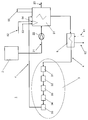
도 1 은 본 발명의 제 1 실시형태를 나타내는 도면이다.
도 2 는 본 발명의 제 2 실시형태를 나타내는 도면이다.
도 3 은 본 발명의 제 3 실시형태를 나타내는 도면이다. 1 is a diagram showing a first embodiment of the present invention.
2 is a diagram showing a second embodiment of the present invention.
3 is a view showing a third embodiment of the present invention.
도 1 에서 부유 LNG 저장 및 재가스화 유닛 (FSRU) 은 일반적으로 참조 번호 1 로 표시한다. FSRU 는 보통, 추진 수단을 갖지 않는 해양 선박 형태인, 영구적으로 정박된 터미널이다. FSRU 에는, 재가스화 장비 및 호텔 소비자를 위해, 이 실시형태에서 참조 번호 3 으로 표시된 동력 장치로 나타낸 동력 발생 설비, 뿐만아니라 LNG 저장 및 LNG 기화 설비가 제공된다. FSRU 에는 보통 기화된 LNG 를 해안 및 최종 소비자에게 전송하기 위한 적절한 수송관에 연결하기 위한 가스 이송 수단 (도시되지 않음) 이 또한 제공된다. In FIG. 1 the floating LNG storage and regasification unit (FSRU) is indicated generally by
FSRU 는 고압 펌프 (22) 가 제공되는 이송 라인 (21) 을 통하여 기화 유닛 (5) 에 연결되는 LNG 저장 탱크 (2) 를 포함한다. 열 교환기로서 배치되는, 기화 유닛 (5) 은 LNG 저장 탱크로부터 액화 형태의 LNG 를 수용하고 가열 후에 천연 가스로서 배출 라인 (23) 을 통하여 이를 배출한다. The FSRU comprises an
동력 장치 (3) 는 기화 유닛을 위한 열을 발생시키기 위해 구성된다. 기화 유닛 (5) 을 위한 열은 제 1 가열 매체가 순환되고 기화 유닛 (5) 에 직접적으로 연결되는 단일 루프를 형성하는 단일 가열 회로 (4) 를 통하여 제공된다. 이러한 단일 가열 회로 (4) 는 동력 장치 (3) 의 모든 이용 가능한 열원으로부터의 열을 수집하기 위해 동력 장치 (3) 로 배향되고 상기 열을 LNG 의 기화를 위한 제 1 가열 매체를 통하여 기화 유닛 (5) 에 전달하기 위해 기화 유닛 (5) 으로 직접적으로 유도된다. The
이러한 실시형태에서 동력 장치 (3) 는 가스 연료 공급식 내연기관이고, 이에 의해 열원은, 도면에 단지 개략적으로 표시되는 엔진 고온 (HT) 냉각수 회로 (31), 엔진 저온 (LT) 냉각수 회로 (32), 윤활유 회로 (33), 엔진 자켓 물 회로 (34), 및 배기 가스 열 교환기 (35) (배기 가스 보일러) 를 포함한다. In this embodiment the
그 결과, 본 발명에 따르면, 동력 장치 (3) 로부터의 모든 회수 가능한 열, 또는 폐열이 단일 가열 회로 (4) 안에 수집되고 배향되며 그 후 제 1 가열 매체를 통하여 기화 유닛 (5) 에서 직접적으로 활용된다. 이는 FSRU 에 대한 낮은 투자 비용으로 매우 높은 수준의 전체 에너지 효율을 보장한다. As a result, according to the invention, all recoverable heat or waste heat from the
본 발명에 따르면 FSRU 에는 단일 가열 회로 (4) 에 직접적으로 연결되는 보조 열 교환기 (6) 가 또한 제공된다. 보조 열 교환기 (6) 에는 해수 회로 (61, 62) 가 제공되며, 참조번호 61 은 해수의 유입을 표시하고 참조 번호 62 는 해수의 유출을 표시한다. 보조 열 교환기는 재가스화 장비가 사용되지 않을 때 동력 장치 (3) 의 백업 냉각기로서 기능할 수 있다. According to the invention the FSRU is also provided with an
도 2 는 침지된 연소 기화 유닛 (SCV) 과 관련하여 본 발명의 제 2 실시형태를 나타낸다. 2 shows a second embodiment of the invention in connection with a submerged combustion vaporization unit (SCV).
도 1 과 관련하여, 부유 LNG 저장 및 재가스화 유닛 (FSRU) 은 일반적으로 참조 번호 1 로 표시된다. FSRU 는 보통, 추진 수단을 갖지 않는 해양 선박 형태인, 영구적으로 정박된 터미널이다. FSRU 에는 재가스화 장비 및 호텔 소비자를 위해, 이 실시형태에서 참조 번호 3 으로 표시된 동력 장치로 나타낸 동력 발생 설비, 뿐만아니라 LNG 저장 및 LNG 기화 설비가 제공된다. FSRU 에는 보통 기화된 LNG 를 해안 및 최종 소비자에게 전송하기 위한 적절한 수송관에 연결하기 위한 가스 이송 수단 (도시되지 않음) 이 또한 제공된다. In connection with FIG. 1, a floating LNG storage and regasification unit (FSRU) is indicated generally by
FSRU 는 고압 펌프 (22) 가 제공되는 이송 라인 (21) 을 통하여 기화 유닛 (51) 에 연결되는 LNG 저장 탱크 (2) 를 포함한다. 열 교환기로서 배치되는, 기화 유닛 (51) 은 LNG 저장 탱크로부터 액화 형태의 LNG 를 수용하고 가열 후에 천연 가스로서 배출 라인 (23) 을 통하여 이를 배출한다. 동력 장치 (3) 는 기화 유닛을 위한 열을 발생시키기 위해 구성된다. The FSRU comprises an
이러한 실시형태에서, 기화 유닛 (51) 은 소위 침지된 연소 기화 유닛 (SCV) 을 나타낸다. 기화 유닛 (51) 은 기본적으로는, 연료 이송 라인 (52) 으로 표시된 바와 같이 천연 가스에 의해 연료 공급되고, 공기 공급 라인 (53) 으로 표시된 바와 같이 연소 가스에 의해 보충되는 천연 가스 버너 (54) 를 통하여 가열되는 수조를 형성한다. 배기 가스 배출은 참조 번호 55 로 표시된다. 이러한 구성에서 천연 가스 버너 (54) 에 의해 제공되는 열은 기화 공정을 위한 주 열원을 제공한다. 천연 가스 버너 (54) 를 위한 천연 가스는 FSRU 에 저장되는 LNG 로부터 자연스럽게 이용 가능하다. In this embodiment, the
이러한 주 열원 이외에, 기화 공정을 위한 열은 제 1 가열 매체가 순환되고 기화 유닛 (51) 에 직접적으로 연결되는 단일 루프를 형성하는 단일 가열 회로 (4) 를 통하여 또한 제공된다. 이러한 단일 가열 회로 (4) 는 동력 장치 (4) 의 모든 이용 가능한 열원으로부터 열을 수집하기 위해 동력 장치 (3) 를 통하여 배향된다. 단일 가열 회로 (4) 는 그 후 제 1 가열 매체에 의해 제공되는 열을 통하여 기화 유닛 (51) 의 수조의 온도를 상승시킴으로써 기화 유닛 (51) 을 위한 보충 열원으로서 상기 열을 전달하기 위해 기화 유닛 (51) 의 수조를 통하여 직접적으로 유도된다. 그 결과, 천연 가스 버너 (54) 에 의해 제공되어야 하는 열은 더 적다. In addition to this main heat source, heat for the vaporization process is also provided through a
이러한 실시형태에서 동력 장치 (3) 는 가스 연료 공급식 내연기관이고, 이에 의해 열원은, 도면에 단지 개략적으로 표시되는 엔진 고온 (HT) 냉각수 회로 (31), 엔진 저온 (LT) 냉각수 회로 (32), 윤활유 회로 (33), 엔진 자켓 물 회로 (34), 및 배기 가스 열 교환기 (35) (배기 가스 보일러) 를 포함한다. In this embodiment the
그 결과, 본 발명에 따르면, 동력 장치 (3) 로부터의 모든 회수 가능한 열, 또는 폐열이 단일 가열 회로 (4) 안에 수집되고 배향되며 그 후 제 1 가열 매체를 통하여 기화 유닛 (51) 에서 직접적으로 활용된다. 이는 FSRU 에 대한 낮은 투자 비용으로 매우 높은 수준의 전체 에너지 효율을 보장한다. As a result, according to the invention, all recoverable heat or waste heat from the
상기 논의된 침지된 연소 기화 유닛 (SCV) 과 관련하여 이로운 점은 동력 장치로부터의 추가적인 폐열 공급에 의해, 더 낮은 가스 소비에서 특히 나타날 수 있다. 이는 더 낮은 배출물과 비용 절약을 초래한다. The advantages associated with the submerged combustion vaporization unit (SCV) discussed above can be seen particularly at lower gas consumption by the additional waste heat supply from the power plant. This results in lower emissions and cost savings.
본 발명에 따르면 FSRU 에는 단일 가열 회로 (4) 에 직접적으로 연결되는 보조 열 교환기 (6) 가 또한 제공된다. 보조 열 교환기 (6) 에는 해수 회로 (61, 62) 가 제공되고, 참조 번호 61 은 해수의 유입을 표시하고 참조 번호 62 는 해수의 유출을 표시한다. 이러한 보조 열 교환기는 재가스화 장비가 사용되지 않을 때 동력 장치 (3) 의 백업 냉각기로서 기능할 수 있다. According to the invention the FSRU is also provided with an
도 3 은 오픈랙식 기화기 (ORV) 와 관련하여 본 발명의 제 3 실시형태를 나타낸다. 3 shows a third embodiment of the invention in connection with an open rack vaporizer (ORV).
도 1 과 관련하여, 부유 LNG 저장 및 재가스화 유닛 (FSRU) 은 일반적으로 참조 번호 1 로 표시된다. FSRU 는 보통, 추진 수단을 갖지 않는 해양 선박 형태인, 영구적으로 정박된 터미널이다. FSRU 에는 재가스화 장비 및 호텔 소비자를 위해, 이 실시형태에서 참조 번호 3 으로 표시된 동력 장치로 나타낸 동력 발생 설비, 뿐만아니라 LNG 저장 및 LNG 기화 설비가 제공된다. FSRU 에는 보통 기화된 LNG 를 해안 및 최종 소비자에게 전송하기 위한 적절한 수송관에 연결하기 위한 가스 이송 수단 (도시되지 않음) 이 또한 제공된다. In connection with FIG. 1, a floating LNG storage and regasification unit (FSRU) is indicated generally by
FSRU 는 고압 펌프 (22) 가 제공되는 이송 라인 (21) 을 통하여 기화 유닛 (56) 에 연결되는 LNG 저장 탱크 (2) 를 포함한다. 열 교환기로서 배치되는, 기화 유닛 (56) 은 LNG 저장 탱크로부터 액화 형태의 LNG 를 수용하고 가열 후에 천연 가스로서 배출 라인 (23) 을 통하여 배출한다. 동력 장치 (3) 는 기화 유닛을 위한 열을 발생시키기 위해 구성된다. The FSRU comprises an
이러한 실시형태에서, 기화 유닛 (56) 은 소위 오픈랙식 기화기 (ORV) 를 나타내고, 이에 의해 기화 유닛 (56) 은 해수 회로 (61, 62) 에 연결되며, 참조 번호 61 은 해수의 유입을 표시하고 참조 번호 62 는 해수의 유출을 표시한다. 따라서, 제 2 가열 매체를 형성하는 해수는 보조 열 교환기 (6) 및 또한 기화 유닛 (56) 을 통하여 유도되고 기화 유닛 (56) 을 위한 주 열원을 제공한다. In this embodiment, the
이러한 주 열원 이외에, 기화 공정을 위한 열은 제 1 가열 매체가 순환되고 기화 유닛 (56) 의 해수 회로 (61, 62) 가 통과하여 유도되는 보조 열 교환기 (6) 에 직접적으로 연결되는 단일 루프를 형성하는 단일 가열 회로 (4) 를 통하여 또한 제공된다. 이러한 단일 가열 회로 (4) 는 동력 장치 (3) 의 모든 이용 가능한 열원으로부터 열을 수집하기 위해 동력 장치 (3) 를 통하여 배향되고 해수가 기화 유닛 (56) 을 통하여 유도되기 전에 해수 회로 (61, 62) 의 해수를 가열하기 위해 보조 열 교환기 (6) 에 직접적으로 유도된다. 단일 가열 회로 (4) 는 따라서 단일 가열 회로 (4) 에서 순환되는 제 1 가열 매체를 통하여, 제 2 가열 매체, 즉 기화 유닛 (56) 을 통하여 순환하는 해수의 온도를 상승시킴으로써 기화 유닛 (56) 을 위한 보충 열원으로서의 기능을 한다. In addition to this main heat source, the heat for the vaporization process comprises a single loop in which the first heating medium is circulated and directly connected to the
이러한 실시형태에서 동력 장치 (3) 는 가스 연료 공급식 내연기관이고, 이에 의해 열원은, 도면에 단지 개략적으로 표시되는 엔진 고온 (HT) 냉각수 회로 (31), 엔진 저온 (LT) 냉각수 회로 (32), 윤활유 회로 (33), 엔진 자켓 물 회로 (34), 및 배기 가스 열 교환기 (35) (배기 가스 보일러) 를 포함한다. In this embodiment the
그 결과, 본 발명에 따르면, 동력 장치 (3) 로부터의 모든 회수 가능한 열, 또는 폐열이 단일 가열 회로 (4) 안에 수집되고 배향되며 그 후 제 1 가열 매체와 제 2 가열 매체 사이의 열 교환기를 통하여 기화 유닛 (56) 을 위한 추가적인 열을 제공하는데 활용된다. 이는 FSRU 에 대한 낮은 투자 비용으로 매우 높은 수준의 전체 에너지 효율을 보장한다. As a result, according to the invention, all recoverable heat or waste heat from the
상기 언급된 오픈랙식 기화기 (ORV) 와 관련하여 이로운 점은 동력 장치로부터의 추가적인 폐열 공급에 의해, 더 낮은 해수 펌핑 파워 소비에서 특히 나타날 수 있다. 이는 더 낮은 배출물과 비용 절약을 초래한다. The advantages associated with the above mentioned Open Rack Vaporizers (ORV) can be seen in particular at lower sea water pumping power consumption, by the additional waste heat supply from the power plant. This results in lower emissions and cost savings.
본 발명에 따르면, 단일 가열 회로 (4) 에 연결되는 보조 열 교환기 (6) 는 도 1 에 따른 실시형태와 관련하여 재가스화 장비가 사용되지 않을 때 동력 장치 (3) 를 위한 백업 냉각기로서 기능할 수 있다. According to the invention, the
설명 및 이와 관련된 도면은 본 발명의 기본 아이디어를 명백하게 하기 위한 것이다. 본 발명은 다음의 청구항의 내용 내에서 상세하게 변할 수 있다. The description and the associated drawings are intended to clarify the basic idea of the invention. The invention may vary in detail within the context of the following claims.
Claims (16)
Applications Claiming Priority (2)
| Application Number | Priority Date | Filing Date | Title |
|---|---|---|---|
| FI20075857 | 2007-11-30 | ||
| FI20075857A FI125981B (en) | 2007-11-30 | 2007-11-30 | Liquid unit for storage and re-evaporation of liquefied gas and procedure for re-evaporation of liquefied gas at said unit |
Publications (1)
| Publication Number | Publication Date |
|---|---|
| KR20100108529A true KR20100108529A (en) | 2010-10-07 |
Family
ID=38786786
Family Applications (1)
| Application Number | Title | Priority Date | Filing Date |
|---|---|---|---|
| KR1020107013698A KR20100108529A (en) | 2007-11-30 | 2008-11-14 | Floating lng storage and re-gasification unit and method for re-gasification of lng on said unit |
Country Status (9)
| Country | Link |
|---|---|
| US (1) | US20100229573A1 (en) |
| EP (1) | EP2215398B1 (en) |
| JP (1) | JP5395089B2 (en) |
| KR (1) | KR20100108529A (en) |
| CN (1) | CN101918749B (en) |
| AT (1) | ATE503148T1 (en) |
| DE (1) | DE602008005791D1 (en) |
| FI (1) | FI125981B (en) |
| WO (1) | WO2009068731A2 (en) |
Families Citing this family (22)
| Publication number | Priority date | Publication date | Assignee | Title |
|---|---|---|---|---|
| EP2313681A4 (en) * | 2008-07-17 | 2017-11-01 | Fluor Technologies Corporation | Configurations and methods for waste heat recovery and ambient air vaporizers in lng regasification |
| NO332708B1 (en) * | 2009-05-14 | 2012-12-17 | Sevan Marine Asa | Regassification with power plants |
| DE102009057055A1 (en) * | 2009-12-04 | 2011-06-09 | Linde Ag | Process and apparatus for the evaporation of cryogenic media |
| EP2547580A4 (en) | 2010-05-20 | 2017-05-31 | Excelerate Energy Limited Partnership | Systems and methods for treatment of lng cargo tanks |
| JP5653666B2 (en) * | 2010-07-08 | 2015-01-14 | 三菱重工業株式会社 | Regasification plant for floating structures |
| KR101756259B1 (en) * | 2010-07-09 | 2017-07-12 | 대우조선해양 주식회사 | Fuel feed system of dual fuel engine for ship |
| KR101951174B1 (en) * | 2011-01-28 | 2019-02-25 | 엑손모빌 업스트림 리서치 캄파니 | Regasification plant |
| KR101335608B1 (en) * | 2011-04-14 | 2013-12-02 | 대우조선해양 주식회사 | Fresh water generating system |
| US9494281B2 (en) * | 2011-11-17 | 2016-11-15 | Air Products And Chemicals, Inc. | Compressor assemblies and methods to minimize venting of a process gas during startup operations |
| FI125018B (en) * | 2012-02-29 | 2015-04-30 | Wärtsilä Finland Oy | LNG tank |
| US20140123916A1 (en) * | 2012-11-05 | 2014-05-08 | Electro-Motive Diesel, Inc. | Utilizing Locomotive Electrical Locker to Warm Liquid Natural Gas |
| US9752727B2 (en) * | 2012-11-30 | 2017-09-05 | Chart Inc. | Heat management system and method for cryogenic liquid dispensing systems |
| JP6310265B2 (en) * | 2014-02-06 | 2018-04-11 | 新潟原動機株式会社 | Liquefied gas supply system for ship propulsion gas fuel engine |
| JP2016008042A (en) * | 2014-06-25 | 2016-01-18 | 潮冷熱株式会社 | Binary power generation system for lng ship |
| CN104315339B (en) * | 2014-10-27 | 2016-02-24 | 中国海洋石油总公司 | Be applied to LNG cascade regas system and the regasification process of offshore floating type LNG regasification plant |
| US20170097178A1 (en) * | 2015-10-05 | 2017-04-06 | Crowley Maritime Corporation | Lng gasification systems and methods |
| WO2018066860A1 (en) * | 2016-10-05 | 2018-04-12 | 대우조선해양 주식회사 | System and method for supplying fuel gas for ship |
| CN107514541B (en) * | 2017-09-26 | 2023-05-05 | 北京泰恩博能燃气设备技术有限公司 | Floating liquefied natural gas storage and gasification device, control system and control method |
| JP7011516B2 (en) * | 2018-03-30 | 2022-01-26 | 株式会社神戸製鋼所 | Liquefied natural gas vaporization system |
| CN109026235A (en) * | 2018-06-15 | 2018-12-18 | 沪东中华造船(集团)有限公司 | A kind of cold energy generation system for liquefied natural gas floating storage regasification plant |
| CN109723966B (en) * | 2019-01-25 | 2020-10-23 | 太平洋海洋工程(舟山)有限公司 | Liquefied natural gas regasification system for FSRU |
| CN113581364B (en) * | 2021-09-07 | 2022-09-16 | 中海石油气电集团有限责任公司 | Seawater supply system and method for LNG-FSRU |
Family Cites Families (23)
| Publication number | Priority date | Publication date | Assignee | Title |
|---|---|---|---|---|
| US3818893A (en) * | 1973-08-07 | 1974-06-25 | T Watanabe | Submerged combustion type vaporizer |
| NL7600308A (en) * | 1975-02-07 | 1976-08-10 | Sulzer Ag | METHOD AND EQUIPMENT FOR THE VAPORIZATION AND HEATING OF LIQUID NATURAL GAS. |
| WO1983002820A1 (en) * | 1982-02-03 | 1983-08-18 | Söllner, Robert | Heating or cooling device |
| GB8313907D0 (en) * | 1983-05-19 | 1983-06-22 | Sabre Engines | Engine cooling system |
| JPS6363186U (en) * | 1986-10-07 | 1988-04-26 | ||
| JPH0535280Y2 (en) * | 1988-01-12 | 1993-09-07 | ||
| JPH1061895A (en) * | 1996-08-26 | 1998-03-06 | Ishikawajima Harima Heavy Ind Co Ltd | Condensate recovering device for lng gasifier |
| US6089022A (en) * | 1998-03-18 | 2000-07-18 | Mobil Oil Corporation | Regasification of liquefied natural gas (LNG) aboard a transport vessel |
| JP2001263894A (en) * | 2000-03-23 | 2001-09-26 | Ishikawajima Harima Heavy Ind Co Ltd | Cryogenic liquid storage facility |
| JP4548694B2 (en) * | 2001-04-20 | 2010-09-22 | 本田技研工業株式会社 | Engine exhaust heat recovery device |
| JP2002340296A (en) * | 2001-05-16 | 2002-11-27 | Sumitomo Precision Prod Co Ltd | Liquefied gas vaporizing and heating device |
| MXPA04008283A (en) * | 2002-02-27 | 2005-07-26 | Excelerate Ltd Partnership | Method and apparatus for the regasification of lng onboard a carrier. |
| JP4584589B2 (en) * | 2002-03-29 | 2010-11-24 | エクセルレイト・エナジー・リミテッド・パートナーシップ | Improved LNG carrier |
| US6598408B1 (en) * | 2002-03-29 | 2003-07-29 | El Paso Corporation | Method and apparatus for transporting LNG |
| NO330955B1 (en) * | 2003-04-30 | 2011-08-22 | Torp Tech As | Unloading and cargo evaporation device for ships |
| JP4317187B2 (en) * | 2003-06-05 | 2009-08-19 | フルオー・テクノロジーズ・コーポレイシヨン | Composition and method for regasification of liquefied natural gas |
| KR20090018177A (en) * | 2003-08-12 | 2009-02-19 | 익셀러레이트 에너지 리미티드 파트너쉽 | Shipboard regasification for lng carriers with alternate propulsion plants |
| US20050115248A1 (en) * | 2003-10-29 | 2005-06-02 | Koehler Gregory J. | Liquefied natural gas structure |
| JP2005226665A (en) * | 2004-02-10 | 2005-08-25 | Osaka Gas Co Ltd | Liquefied natural gas vaporizing system |
| US20060156744A1 (en) * | 2004-11-08 | 2006-07-20 | Cusiter James M | Liquefied natural gas floating storage regasification unit |
| WO2007039480A1 (en) * | 2005-09-21 | 2007-04-12 | Exmar | Liquefied natural gas regasification plant and method with heat recovery |
| FI121745B (en) * | 2005-12-28 | 2011-03-31 | Waertsilae Finland Oy | Arrangement and method for producing cooling energy for the refrigerant circulation system in a watercraft |
| JP2007238026A (en) * | 2006-03-10 | 2007-09-20 | Toyota Motor Corp | Exhaust system heat exchanger |
-
2007
- 2007-11-30 FI FI20075857A patent/FI125981B/en not_active IP Right Cessation
-
2008
- 2008-11-14 WO PCT/FI2008/050661 patent/WO2009068731A2/en active Application Filing
- 2008-11-14 US US12/679,435 patent/US20100229573A1/en not_active Abandoned
- 2008-11-14 JP JP2010535415A patent/JP5395089B2/en not_active Expired - Fee Related
- 2008-11-14 EP EP08854103A patent/EP2215398B1/en not_active Not-in-force
- 2008-11-14 AT AT08854103T patent/ATE503148T1/en not_active IP Right Cessation
- 2008-11-14 CN CN2008801144440A patent/CN101918749B/en not_active Expired - Fee Related
- 2008-11-14 DE DE602008005791T patent/DE602008005791D1/en active Active
- 2008-11-14 KR KR1020107013698A patent/KR20100108529A/en not_active Application Discontinuation
Also Published As
| Publication number | Publication date |
|---|---|
| JP5395089B2 (en) | 2014-01-22 |
| FI125981B (en) | 2016-05-13 |
| WO2009068731A2 (en) | 2009-06-04 |
| EP2215398A2 (en) | 2010-08-11 |
| FI20075857A0 (en) | 2007-11-30 |
| CN101918749A (en) | 2010-12-15 |
| FI20075857A (en) | 2009-05-31 |
| WO2009068731A3 (en) | 2009-07-16 |
| EP2215398B1 (en) | 2011-03-23 |
| US20100229573A1 (en) | 2010-09-16 |
| JP2011504991A (en) | 2011-02-17 |
| ATE503148T1 (en) | 2011-04-15 |
| DE602008005791D1 (en) | 2011-05-05 |
| CN101918749B (en) | 2012-05-23 |
Similar Documents
| Publication | Publication Date | Title |
|---|---|---|
| KR20100108529A (en) | Floating lng storage and re-gasification unit and method for re-gasification of lng on said unit | |
| KR101219365B1 (en) | LNG Regasification Facility and Method in the Vessel | |
| WO2007039480A1 (en) | Liquefied natural gas regasification plant and method with heat recovery | |
| US20080047280A1 (en) | Heat recovery system | |
| KR101229620B1 (en) | Liquefied Natural Gas Supply System for Marine Vessel or Offshore Plant | |
| JP5254716B2 (en) | Floating structure | |
| KR101295446B1 (en) | Fuel gas supply system of LNG carrier | |
| KR20040083005A (en) | Feeding energy to a gas terminal from a ship for transporting liquefied gas | |
| KR20120048598A (en) | Gas-fired superconductive electrically propelled ship | |
| KR102631877B1 (en) | Floating system on water | |
| KR20110027864A (en) | Waster heat recovery system with the exhaust gas from the gas combustion unit | |
| KR20120005779A (en) | Fuel feed system of dual fuel engine for ship | |
| KR20160059065A (en) | Operating energy saving floating lng re-gasification power plant | |
| KR20100002826A (en) | Lng regasification facilty using fresh water heating | |
| KR20160049122A (en) | Floating lng re-gasification power plant reducing sea water suction load | |
| KR101933883B1 (en) | Gas turbine generating apparatus and startup operating method of the same | |
| KR20180046627A (en) | Surplus bog treatment apppratus for gas turbine generating system | |
| KR101616333B1 (en) | Lng regasification device | |
| KR101397809B1 (en) | A fuel gas supply system of liquefied natural gas | |
| KR102239297B1 (en) | Floating marine structure with electric power generator | |
| KR101280216B1 (en) | Fuel gas supply system of the direct heat exchange form using boiler steam | |
| KR101521611B1 (en) | Heating system of coffer dam in ship | |
| KR102282403B1 (en) | Marine Fuel Gas Supply System | |
| KR20220152592A (en) | Gas treatment system of hydrogen carrier | |
| KR101397734B1 (en) | A fuel gas supply system of liquefied natural gas |
Legal Events
| Date | Code | Title | Description |
|---|---|---|---|
| A201 | Request for examination | ||
| E902 | Notification of reason for refusal | ||
| E601 | Decision to refuse application |