KR20100096231A - Led lamp power management system and method - Google Patents
Led lamp power management system and method Download PDFInfo
- Publication number
- KR20100096231A KR20100096231A KR1020107015021A KR20107015021A KR20100096231A KR 20100096231 A KR20100096231 A KR 20100096231A KR 1020107015021 A KR1020107015021 A KR 1020107015021A KR 20107015021 A KR20107015021 A KR 20107015021A KR 20100096231 A KR20100096231 A KR 20100096231A
- Authority
- KR
- South Korea
- Prior art keywords
- led
- led lamp
- channel
- power
- shunt
- Prior art date
Links
Images
Classifications
-
- H—ELECTRICITY
- H05—ELECTRIC TECHNIQUES NOT OTHERWISE PROVIDED FOR
- H05B—ELECTRIC HEATING; ELECTRIC LIGHT SOURCES NOT OTHERWISE PROVIDED FOR; CIRCUIT ARRANGEMENTS FOR ELECTRIC LIGHT SOURCES, IN GENERAL
- H05B45/00—Circuit arrangements for operating light-emitting diodes [LED]
- H05B45/40—Details of LED load circuits
- H05B45/44—Details of LED load circuits with an active control inside an LED matrix
- H05B45/48—Details of LED load circuits with an active control inside an LED matrix having LEDs organised in strings and incorporating parallel shunting devices
-
- B—PERFORMING OPERATIONS; TRANSPORTING
- B60—VEHICLES IN GENERAL
- B60Q—ARRANGEMENT OF SIGNALLING OR LIGHTING DEVICES, THE MOUNTING OR SUPPORTING THEREOF OR CIRCUITS THEREFOR, FOR VEHICLES IN GENERAL
- B60Q11/00—Arrangement of monitoring devices for devices provided for in groups B60Q1/00 - B60Q9/00
-
- H—ELECTRICITY
- H05—ELECTRIC TECHNIQUES NOT OTHERWISE PROVIDED FOR
- H05B—ELECTRIC HEATING; ELECTRIC LIGHT SOURCES NOT OTHERWISE PROVIDED FOR; CIRCUIT ARRANGEMENTS FOR ELECTRIC LIGHT SOURCES, IN GENERAL
- H05B45/00—Circuit arrangements for operating light-emitting diodes [LED]
- H05B45/10—Controlling the intensity of the light
-
- H—ELECTRICITY
- H05—ELECTRIC TECHNIQUES NOT OTHERWISE PROVIDED FOR
- H05B—ELECTRIC HEATING; ELECTRIC LIGHT SOURCES NOT OTHERWISE PROVIDED FOR; CIRCUIT ARRANGEMENTS FOR ELECTRIC LIGHT SOURCES, IN GENERAL
- H05B45/00—Circuit arrangements for operating light-emitting diodes [LED]
- H05B45/20—Controlling the colour of the light
- H05B45/22—Controlling the colour of the light using optical feedback
-
- H—ELECTRICITY
- H05—ELECTRIC TECHNIQUES NOT OTHERWISE PROVIDED FOR
- H05B—ELECTRIC HEATING; ELECTRIC LIGHT SOURCES NOT OTHERWISE PROVIDED FOR; CIRCUIT ARRANGEMENTS FOR ELECTRIC LIGHT SOURCES, IN GENERAL
- H05B45/00—Circuit arrangements for operating light-emitting diodes [LED]
- H05B45/20—Controlling the colour of the light
- H05B45/28—Controlling the colour of the light using temperature feedback
-
- H—ELECTRICITY
- H05—ELECTRIC TECHNIQUES NOT OTHERWISE PROVIDED FOR
- H05B—ELECTRIC HEATING; ELECTRIC LIGHT SOURCES NOT OTHERWISE PROVIDED FOR; CIRCUIT ARRANGEMENTS FOR ELECTRIC LIGHT SOURCES, IN GENERAL
- H05B45/00—Circuit arrangements for operating light-emitting diodes [LED]
- H05B45/30—Driver circuits
- H05B45/37—Converter circuits
- H05B45/3725—Switched mode power supply [SMPS]
- H05B45/375—Switched mode power supply [SMPS] using buck topology
-
- H—ELECTRICITY
- H05—ELECTRIC TECHNIQUES NOT OTHERWISE PROVIDED FOR
- H05B—ELECTRIC HEATING; ELECTRIC LIGHT SOURCES NOT OTHERWISE PROVIDED FOR; CIRCUIT ARRANGEMENTS FOR ELECTRIC LIGHT SOURCES, IN GENERAL
- H05B45/00—Circuit arrangements for operating light-emitting diodes [LED]
- H05B45/50—Circuit arrangements for operating light-emitting diodes [LED] responsive to malfunctions or undesirable behaviour of LEDs; responsive to LED life; Protective circuits
-
- Y—GENERAL TAGGING OF NEW TECHNOLOGICAL DEVELOPMENTS; GENERAL TAGGING OF CROSS-SECTIONAL TECHNOLOGIES SPANNING OVER SEVERAL SECTIONS OF THE IPC; TECHNICAL SUBJECTS COVERED BY FORMER USPC CROSS-REFERENCE ART COLLECTIONS [XRACs] AND DIGESTS
- Y02—TECHNOLOGIES OR APPLICATIONS FOR MITIGATION OR ADAPTATION AGAINST CLIMATE CHANGE
- Y02B—CLIMATE CHANGE MITIGATION TECHNOLOGIES RELATED TO BUILDINGS, e.g. HOUSING, HOUSE APPLIANCES OR RELATED END-USER APPLICATIONS
- Y02B20/00—Energy efficient lighting technologies, e.g. halogen lamps or gas discharge lamps
- Y02B20/30—Semiconductor lamps, e.g. solid state lamps [SSL] light emitting diodes [LED] or organic LED [OLED]
Abstract
LED 제어기(58); 및 상기 LED 제어기(58)에 동작 가능하게 접속되는 복수의 LED 채널(60)-상기 복수의 LED 채널(60)의 각각은 적어도 하나의 션트된 LED 회로(83)와 직렬인 채널 스위치(62)를 구비하고, 상기 션트된 LED 회로(83)는 LED 소스(80)와 병렬인 션트 스위치(68)를 구비함-을 구비하는 LED 램프를 포함하는 LED 램프 전력 관리 시스템 및 방법이 개시된다. 상기 LED 제어기(58)는 LED 램프 전자 회로 전력 손실(Ploss)이 LED 램프 전자 회로 전력 손실 한계(Plim)를 초과할 때 상기 채널 스위치(62) 및 상기 션트 스위치(68) 중 하나에서의 전력 손실을 줄이며, 상기 채널 스위치들(62)의 각각은 상기 LED 제어기(58)로부터 채널 스위치 제어 신호(63)를 수신하고, 상기 션트 스위치들(68)의 각각은 상기 LED 제어기(58)로부터 션트 스위치 제어 신호(69)를 수신한다.LED controller 58; And a plurality of LED channels 60 operatively connected to the LED controller 58—each of the plurality of LED channels 60 in series with at least one shunted LED circuit 83. And a LED lamp having a shunt switch 68, wherein the shunted LED circuit 83 has a shunt switch 68 in parallel with the LED source 80. The LED controller 58 is configured at one of the channel switch 62 and the shunt switch 68 when the LED lamp electronic circuit power loss P loss exceeds the LED lamp electronic circuit power loss limit P lim . Reduce power loss, each of the channel switches 62 receives a channel switch control signal 63 from the LED controller 58, and each of the shunt switches 68 from the LED controller 58; A shunt switch control signal 69 is received.

Description
본 발명은 U.S. Department of Energy Contract Number DE-FC26-05NT42342에 의해 제공되는 미국 정부 지원으로 이루어졌다. 미국 정부는 본 발명에 대한 소정의 권리를 갖는다.The present invention is U.S. This was done with US government support provided by the Department of Energy Contract Number DE-FC26-05NT42342. The United States government has certain rights in the invention.
본 발명의 기술적 분야는 전원, 특히 LED 램프 전력 관리 시스템 및 방법이다.The technical field of the invention is a power source, in particular an LED lamp power management system and method.
전통적으로, 백열 및 형광 조명 장치들은 자동차 및 기타 차량에서의 광원들로서 사용되어 왔다. 그러나, 발광 다이오드(LED)의 커다란 기술 진보는 긴 동작 수명, 높은 효율 및 낮은 프로파일로 인해 LED를 차량에 사용하는 데에 매력적이게 하였다. LED들은 이제 거의 소형 형광 램프만큼 효율적으로 백색광을 생성할 수 있으며, 효율은 증가할 것으로 예상된다. LED들의 에너지 절약을 충분히 실현하기 위해서는, 이들을 구동하는 전자 장치들도 효율적이어야 한다.Traditionally, incandescent and fluorescent lighting devices have been used as light sources in automobiles and other vehicles. However, significant technological advances in light emitting diodes (LEDs) have made LEDs attractive for use in vehicles due to their long operating life, high efficiency and low profile. LEDs can now produce white light almost as efficiently as compact fluorescent lamps, and the efficiency is expected to increase. In order to fully realize the energy savings of the LEDs, the electronics driving them must also be efficient.
일반 조명 응용들을 위한 LED SIM(LED System-in-Module)과 같은 독립식 LED 램프들이 개발되고 있으며, 이들은 하나 또는 제한된 수의 집적 회로를 갖는 다수의 상이한 컬러의 LED를 사용한다. 집적 회로들은 LED 램프에 대한 감지, 구동 및 제어 회로들을 포함한다. 사용자는 램프 컬러 및 강도를 제어할 수 있다.Independent LED lamps, such as LED System-in-Module (LED SIM) for general lighting applications, are being developed, which use many different color LEDs with one or a limited number of integrated circuits. Integrated circuits include sensing, driving and control circuits for LED lamps. The user can control the lamp color and intensity.
가시 스펙트럼에 걸치는 광을 생성하기 위하여, 상이한 컬러 LED들로부터의 광 출력은 적절한 비율로 결합되어, LED 램프로부터 원하는 컬러를 생성할 수 있다. 예를 들어, 하나의 LED는 적색 광을 생성할 수 있고, 하나는 녹색 광을 생성할 수 있고, 하나는 청색 광을 생성할 수 있다. 적-녹-청(RGB) 조합은 원하는 임의의 컬러를 생성할 수 있으며, 램프의 컬러 렌더링 인덱스(CRI)를 조정하기 위하여 황색(A) 또는 백색(W) 광을 생성하는 LED로 보완될 수 있다. CRI는 램프가 일광 또는 백열 램프와 같은 표준 조명 소스에 비해 얼마나 양호하게 물체들의 컬러들을 렌더링하는지를 나타낸다. RGBA 및 RGBW는 각각 적-녹-청-황 및 적-녹-청-백의 4 LED 램프를 나타내며, 숫자 4는 LED 램프에 사용되는 LED 컬러들의 수를 나타낸다.To produce light that spans the visible spectrum, light output from different color LEDs can be combined at an appropriate ratio, producing the desired color from the LED lamp. For example, one LED can produce red light, one can produce green light, and one can produce blue light. The red-green-blue (RGB) combination can produce any desired color and can be complemented with LEDs that produce yellow (A) or white (W) light to adjust the color rendering index (CRI) of the lamp. have. The CRI indicates how well the lamp renders the colors of the objects compared to standard lighting sources such as daylight or incandescent lamps. RGBA and RGBW represent 4 LED lamps of red-green-blue-yellow and red-green-blue-white, respectively, and the number 4 represents the number of LED colors used in the LED lamp.
4 LED 램프 내의 각각의 LED 소스에 대한 전류는 독립적으로 제어되어, 램프는 전체 범위의 컬러들 및 CRI들을 커버할 수 있다. 4 LED 램프에 대한 하나의 전원 배열은 2개의 병렬 LED 채널이며, LED 채널들 각각에는 직렬인 2개의 LED 소스가 존재한다. 기본적인 전자 토폴로지는 각각의 채널을 통한 전류 흐름을 제어하는 채널 스위치를 구비하는 이력 벅(buck) 컨버터일 수 있다. 각각의 채널을 통한 전류 흐름의 펄스폭 및 진폭 양자는 가변적이다. 이력 동작 상한 및 하한은 펄스 진폭을 설정한다. 각각의 LED 소스와 병렬인 션트 스위치가 특정 LED 소스를 단락시킴으로써 각각의 LED 소스를 통한 전류 흐름을 제어한다.The current for each LED source in a 4 LED lamp is independently controlled so that the lamp can cover a full range of colors and CRIs. One power arrangement for a 4 LED lamp is two parallel LED channels, each of which has two LED sources in series. The basic electronic topology may be a hysteretic buck converter with channel switches that control the flow of current through each channel. Both the pulse width and the amplitude of the current flow through each channel are variable. The hysteresis operation upper and lower limits set the pulse amplitude. A shunt switch in parallel with each LED source controls the flow of current through each LED source by shorting a specific LED source.
이력 한계들은 각각의 채널 내의 LED 소스들 중 하나의 듀티 사이클을 최대화하도록 설정될 수 있다. 채널 전류는 필요한 양의 전류를 생성하기 위하여 감소될 수 있으며, 각각의 채널 내의 하나의 LED 소스의 듀티 사이클은 최대화된다. 이것은 전자 장치들에서 에너지를 절약하며, 일반적으로 높은 전류에서보다 낮은 전류에서 더 효율적으로 광을 방출하는 LED들에 의한 광 생성을 효율적이게 한다.Hysteresis limits can be set to maximize the duty cycle of one of the LED sources in each channel. The channel current can be reduced to produce the required amount of current, with the duty cycle of one LED source in each channel being maximized. This saves energy in electronic devices and generally makes light generation by LEDs emitting light more efficiently at low currents than at high currents.
램프용 LED 소스들은 통상적으로 최적 컬러 및 CRI에서 광을 생성할 때 효율적이도록 선택되는데, 즉 모든 4 LED 소스의 듀티 사이클은 최적 컬러 및 CRI에서 클 것이다. 그러나, 상이한 컬러가 선택될 때 문제들이 발생하며, 램프는 효율적이지 못할 수 있다. 예를 들어, 백색광 생성을 위해 설계된 RGBA 램프는 청색에서의 동작이 선택될 때 청색 및 적색 LED 소스들을 갖는 채널에서 높은 전력 낭비를 가질 것이다. 청색 LED 소스는 대개는 온 상태일 것이며, 즉 청색 LED 소스는 높은 듀티 사이클을 가질 것이며, 적색 LED 소스는 대개는 오프 상태, 즉 낮은 듀티 사이클을 가질 것이다. 이것은 높은 전력 손실로 이어지는데, 그 이유는 적색 LED 소스와 병렬인 션트 스위치가 대부분의 시간 동안 닫혀져서, 적색 LED 소스를 단락시키고, 채널 전류로부터의 전력을 낭비하기 때문이다. 하나의 채널 내에 녹색 및 황색 LED 소스를 갖는 다른 예에서, 사용자가 보다 낮은 CRI와 더불어 높은 광 강도를 요청할 때, 녹색 LED 소스는 완전히 온 상태이고, 황색 LED 소스는 대개는 오프 상태일 것이다. 채널 내의 LED 소스들에 대한 요구의 미스매치는 황색 LED 소스와 병렬인 션트 스위치로부터의 높은 전력 낭비로 이어질 것이다. 220mΩ의 션트 스위치 저항을 통한 1 암페어의 채널 전류에 대하여, 전력 낭비는 0.22 와트이다. 채널들 각각 내의 LED 소스들 중 하나가 주로 오프 상태일 때, 2개의 채널로부터의 결합된 전력 낭비는 0.44 와트이다.LED sources for lamps are typically chosen to be efficient when generating light at optimal color and CRI, ie the duty cycle of all 4 LED sources will be large at optimal color and CRI. However, problems arise when different colors are selected, and the lamp may not be efficient. For example, an RGBA lamp designed for white light generation will have a high power waste in a channel with blue and red LED sources when operation in blue is selected. The blue LED source will usually be on, ie the blue LED source will have a high duty cycle, and the red LED source will usually be off, that is, have a low duty cycle. This leads to high power losses because the shunt switch in parallel with the red LED source closes most of the time, shorting the red LED source and wasting power from the channel current. In another example with green and amber LED sources in one channel, when a user requests high light intensity with a lower CRI, the green LED source will be fully on and the amber LED source will usually be off. Mismatch of the demand for LED sources in the channel will lead to high power waste from the shunt switch in parallel with the yellow LED source. For 1 amp channel current through a 220 mΩ shunt switch resistor, the power dissipation is 0.22 watts. When one of the LED sources in each of the channels is mainly off, the combined power waste from the two channels is 0.44 watts.
션트 스위치에서의 전력 손실은 램프 효율을 줄일 뿐만 아니라, 열 문제들로 유발한다. 션트 스위치에서 손실된 전류는 열로 바뀌며, 이 열은 과열로 인한 동작 문제들을 피하기 위하여 램프 및 그의 관련 칩들 및 회로들로부터 전달되어야 한다. 션트 스위치들 외에도, 2개의 채널에서 전류 레벨을 제어하는 채널 스위치들과 같은 다른 열 소스들도 존재한다. 불행하게도, 램프 응용들은 종종 램프로부터의 개선된 열 전달을 위한 히트 싱크들의 설치를 허가하기 위한 램프 상의 그리고 램프 주위의 제한된 공간을 갖는다. 히트 싱크들의 부족은 LED 램프들이 사용될 수 있는 응용들을 제한하며, 램프가 동작할 수 있는 컬러들의 범위를 제한하다. 램프는 심지어 과열을 방지하기 위하여 그의 설계 동작 포인트로부터 디레이트(derate)될 수도 있다.Power loss in the shunt switch not only reduces lamp efficiency, but also causes thermal problems. The current lost in the shunt switch turns into heat, which must be transferred from the lamp and its associated chips and circuits to avoid operating problems due to overheating. In addition to shunt switches, there are other heat sources such as channel switches that control the current level in the two channels. Unfortunately, lamp applications often have limited space on and around the lamp to permit installation of heat sinks for improved heat transfer from the lamp. The lack of heat sinks limits the applications in which LED lamps can be used and limits the range of colors in which the lamps can operate. The lamp may even be derated from its design operating point to prevent overheating.
위의 단점들을 극복할 LED 램프 전력 관리 시스템 및 방법을 갖추는 것이 바람직할 것이다.It would be desirable to have an LED lamp power management system and method that overcomes the above shortcomings.
본 발명의 일 양태는 LED 제어기; 및 상기 LED 제어기에 동작 가능하게 접속되는 복수의 LED 채널-상기 복수의 LED 채널의 각각은 적어도 하나의 션트된 LED 회로와 직렬인 채널 스위치를 구비하고, 상기 션트된 LED 회로는 LED 소스와 병렬인 션트 스위치를 구비함-을 포함하는 LED 램프를 제공한다. 상기 LED 제어기는 LED 램프 전자 회로 전력 손실(Ploss)이 LED 램프 전자 회로 전력 손실 한계(Plim)를 초과할 때 상기 채널 스위치 및 상기 션트 스위치 중 하나에서의 전력 손실을 줄이며, 상기 채널 스위치들의 각각은 상기 LED 제어기로부터 채널 스위치 제어 신호를 수신하고, 상기 션트 스위치들의 각각은 상기 LED 제어기로부터 션트 스위치 제어 신호를 수신한다.One aspect of the invention is an LED controller; And a plurality of LED channels operatively connected to the LED controller, each of the plurality of LED channels having a channel switch in series with at least one shunted LED circuit, the shunted LED circuit being in parallel with an LED source. An LED lamp comprising a shunt switch is provided. The LED controller when it exceeds an LED lamp electronics power loss (P loss), the LED lamp electronics power loss limit (P lim), reduce the power loss in one of the channel switches and the shunt switch of the channel switch Each receives a channel switch control signal from the LED controller, and each of the shunt switches receives a shunt switch control signal from the LED controller.
본 발명의 다른 양태는 복수의 LED 채널을 구비하는 LED 램프를 제공하는 단계-상기 복수의 LED 채널의 각각은 적어도 하나의 션트된 LED 회로와 직렬인 채널 스위치를 구비하고, 상기 션트된 LED 회로는 LED 소스와 병렬인 션트 스위치를 구비함-; 상기 LED 램프에 대한 LED 램프 설정들을 초기화하는 단계; 상기 LED 램프 설정들로 상기 LED 소스들의 각각에 대한 루멘 프랙션들(lumen fractions)을 계산하는 단계; 상기 루멘 프랙션들로부터 상기 션트 스위치들에 대한 듀티 사이클들을 계산하는 단계; 상기 듀티 사이클들로부터 상기 LED 램프에 대한 LED 램프 전자 장치 전력 손실(Ploss)을 계산하는 단계; 상기 LED 램프 전자 장치 전력 손실(Ploss)이 LED 램프 전자 장치 전력 손실 한계(Plim)보다 작은지의 여부를 판정하는 단계; 상기 LED 램프 전자 장치 전력 손실(Ploss)이 상기 LED 램프 전자 장치 전력 손실 한계(Plim)보다 작지 않을 때, 상기 채널 스위치들에 대한 채널 스위치 전력(Pmain)이 상기 션트 스위치들에 대한 션트 스위치 전력(Pbypass)보다 작은지의 여부를 판정하는 단계; 상기 채널 스위치 전력(Pmain)이 상기 션트 스위치 전력(Pbypass)보다 작지 않을 때, 상기 채널 스위치 전력(Pmain)을 줄이는 단계; 및 상기 채널 스위치 전력(Pmain)이 상기 션트 스위치 전력(Pbypass)보다 작을 때, 상기 션트 스위치 전력(Pbypass)을 줄이는 단계를 포함하는 LED 램프 전력 관리 방법을 제공한다.Another aspect of the invention provides a LED lamp having a plurality of LED channels, each of the plurality of LED channels having a channel switch in series with at least one shunted LED circuit, wherein the shunted LED circuit comprises: Having a shunt switch in parallel with the LED source; Initializing LED lamp settings for the LED lamp; Calculating lumen fractions for each of the LED sources with the LED lamp settings; Calculating duty cycles for the shunt switches from the lumen fractions; Calculating an LED lamp electronics power loss (P loss ) for the LED lamp from the duty cycles; Determining whether the LED lamp electronics power loss P loss is less than an LED lamp electronics power loss limit P lim ; When the LED lamp electronics power loss P loss is not less than the LED lamp electronics power loss limit P lim , the channel switch power P main for the channel switches is the shunt for the shunt switches. Determining whether it is less than the switch power P bypass ; When the channel switch power (P main) is not less than the shunt switch power (P bypass), the step of reducing the channel switch power (P main); And it provides an LED lamp power management method comprising a step of reducing the shunt switch power (P bypass) is less than the shunt switch power (P bypass) the channel switch power (P main).
본 발명의 또 다른 양태는 복수의 LED 채널을 구비하는 LED 램프-상기 복수의 LED 채널의 각각은 적어도 하나의 션트된 LED 회로와 직렬인 채널 스위치를 구비하고, 상기 션트된 LED 회로는 LED 소스와 병렬인 션트 스위치를 구비함-; 상기 LED 램프에 대한 LED 램프 설정들을 초기화하기 위한 수단; 상기 LED 램프 설정들로 상기 LED 소스들의 각각에 대한 루멘 프랙션들을 계산하기 위한 수단; 상기 루멘 프랙션들로부터 상기 션트 스위치들에 대한 듀티 사이클들을 계산하기 위한 수단; 상기 듀티 사이클들로부터 상기 LED 램프에 대한 LED 램프 전자 장치 전력 손실(Ploss)을 계산하기 위한 수단; 상기 LED 램프 전자 장치 전력 손실(Ploss)이 LED 램프 전자 장치 전력 손실 한계(Plim)보다 작은지의 여부를 판정하기 위한 수단; 상기 LED 램프 전자 장치 전력 손실(Ploss)이 상기 LED 램프 전자 장치 전력 손실 한계(Plim)보다 작지 않을 때, 상기 채널 스위치들에 대한 채널 스위치 전력(Pmain)이 상기 션트 스위치들에 대한 션트 스위치 전력(Pbypass)보다 작은지의 여부를 판정하기 위한 수단; 상기 채널 스위치 전력(Pmain)이 상기 션트 스위치 전력(Pbypass)보다 작지 않을 때, 상기 채널 스위치 전력(Pmain)을 줄이기 위한 수단; 및 상기 채널 스위치 전력(Pmain)이 상기 션트 스위치 전력(Pbypass)보다 작을 때, 상기 션트 스위치 전력(Pbypass)을 줄이기 위한 수단을 포함하는 LED 램프 전력 관리 시스템을 제공한다.Another aspect of the invention is an LED lamp having a plurality of LED channels, each of the plurality of LED channels having a channel switch in series with at least one shunted LED circuit, wherein the shunted LED circuit comprises: an LED source; Having a shunt switch in parallel; Means for initializing LED lamp settings for the LED lamp; Means for calculating lumen fractions for each of the LED sources with the LED lamp settings; Means for calculating duty cycles for the shunt switches from the lumen fractions; Means for calculating an LED lamp electronics power loss (P loss ) for the LED lamp from the duty cycles; Means for determining whether the LED lamp electronics power loss P loss is less than an LED lamp electronics power loss limit P lim ; When the LED lamp electronics power loss P loss is not less than the LED lamp electronics power loss limit P lim , the channel switch power P main for the channel switches is the shunt for the shunt switches. Means for determining whether it is less than the switch power P bypass ; When the channel switch power (P main) is not less than the shunt switch power (P bypass), means for reducing the channel switch power (P main); And it provides an LED lamp power management system including the time, the means for reducing the shunt switch power (P bypass) smaller the channel switch power (P main) is greater than the shunt switch power (P bypass).
본 발명의 상기 및 다른 특징들 및 이익들은 첨부 도면들과 관련하여 읽혀지는 아래의 현재의 바람직한 실시예들에 대한 상세한 설명으로부터 더 명확해질 것이다. 상세한 설명 및 도면들은 첨부된 청구항들 및 그들의 균등물들에 의해 정의되는 본 발명의 범위를 한정하는 것이 아니라, 단지 본 발명을 예시한다.These and other features and advantages of the present invention will become more apparent from the following detailed description of the presently preferred embodiments, which is read in connection with the accompanying drawings. The detailed description and drawings do not limit the scope of the invention as defined by the appended claims and their equivalents, but merely illustrate the invention.
도 1은 본 발명에 따른 LED 램프 전력 관리 시스템의 개략도.
도 2는 본 발명에 따른 LED 전력 관리 방법의 흐름도.
도 3은 본 발명에 따른 LED 램프 전력 관리 시스템의 다른 실시예의 개략도.1 is a schematic diagram of an LED lamp power management system according to the present invention;
2 is a flowchart of an LED power management method according to the present invention;
3 is a schematic diagram of another embodiment of an LED lamp power management system according to the present invention;
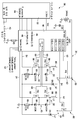
도 1은 본 발명에 따른 LED 램프 전력 관리 시스템의 개략도이다. 이 예에서, LED 램프는 이중 채널 회로, 이중 LED 회로 램프이며, 즉 LED 램프는 LED 채널당 2개의 션트된 LED 회로를 갖는 2개의 LED 채널을 갖는다.1 is a schematic diagram of an LED lamp power management system according to the present invention. In this example, the LED lamp is a dual channel circuit, a dual LED circuit lamp, ie the LED lamp has two LED channels with two shunted LED circuits per LED channel.
전력 관리 시스템을 이용하는 LED 램프(30)는 2개의 LED 채널(60)에 대한 전력을 제어하는 ASIC 이력 제어(50)에 동작 가능하게 접속되는 마이크로컨트롤러(40)를 구비하는 LED 제어기(58)를 포함한다. 각각의 LED 채널(60)은 전압과 공통(common) 사이에 직렬로 접속되는 채널 스위치(62) 및 LED 회로(64)를 구비한다. 각각의 채널 스위치(62)는 LED 채널(60)을 통한 전류 흐름을 제어하기 위해 ASIC 이력 제어(50)로부터 채널 스위치 제어 신호(63)를 수신한다. 이 예에서, 각각의 LED 회로(64)는 2개의 션트된 LED 회로(83) 및 저항기(81)와 직렬인 인덕터(66)와 병렬인 다이오드(67)를 포함한다. 각각의 션트된 LED 회로(83)는 LED 소스(80)와 병렬인 션트 스위치(68)를 포함한다. LED 소스(80)는 원하는 컬러 또는 파장의 광을 생성하기 위하여 서로 직렬 및/또는 병렬로 접속된 하나 이상의 LED를 포함한다. 션트 스위치들(68)의 각각은 ASIC 이력 제어(50)로부터 션트 스위치 제어 신호(69)를 수신한다. 션트 스위치(68)는 그의 관련 LED 소스의 광 출력을 제어하기 위하여 그의 관련 LED 소스 주위의 채널 전류를 단락시킨다. 이 예에서, 기본 전자 장치 토폴로지는 이력 벅 컨버터이다. LED 제어기(58)는 측정된 LED 소스들(80)의 광속, 초기 램프 설정들, 측정된 동작 파라미터들, 동작 파라미터 한계들 등과 같은 동작 데이터를 저장하기 위한 데이터 저장 장치를 포함한다. 이 분야의 기술자들은 LED 제어기(58)가 원하는 기능들을 제공하는 단일 집적 회로 또는 다수의 동작 가능하게 접속된 집적 회로일 수 있다는 것을 알 것이다. 예컨대, LED 제어기(58)는 내장 메모리를 구비하는 마이크로프로세서를 포함하는 단일 집적 회로이거나, 마이크로프로세서를 포함하는 집적 회로 및 메모리를 포함하는 집적 회로인 2개의 집적 회로일 수 있다.The
각각의 LED 소스(80)의 컬러 출력은 특정 목적에 대해 필요한 것과 같은 LED 램프(30)로부터의 광 출력을 생성하도록 선택될 수 있다. 일 실시예에서, LED 소스들은 적-녹-청-황(RGBA)이다. 다른 실시예에서, LED 소스들은 적-녹-청-백(RGBW)이다. 일 실시예에서, 녹색 및 청색 광을 생성하는 LED 소스들(80)은 하나의 LED 채널(60) 내에 있을 수 있으며, 황색 및 적색 광을 생성하는 LED 소스들(80)은 다른 LED 채널(60) 내에 있을 수 있다.The color output of each
마이크로컨트롤러(40)는 컬러 명령 신호, 딤 명령 신호 등과 같은 사용자 입력 신호들(42)을 수신한다. 마이크로컨트롤러(40)는 또한 특정 응용에 필요한 것과 같은 온도 센서 신호, 광 센서 신호 등과 같은 마이크로컨트롤러 피드백 신호들(44)을 수신할 수 있다. 일 실시예에서, 피드백 신호들(44)은 특정 응용에 필요한 바와 같은 온도 센서 신호, 광 센서 신호 등과 같은 제어 피드백 신호들(52)로부터 ASIC 이력 제어(50)에 의해 생성된다. 마이크로컨트롤러(40)는 하이측(HS) 인에이블 신호(46) 및 로우측 펄스폭 변조(LS PWM) 신호(48)를 생성하며, 이들은 사용자 입력 신호들(42) 및 옵션으로서 마이크로컨트롤러 피드백 신호들(44)에 응답하여 ASIC 이력 제어(50)에 제공된다.The
ASIC 이력 제어(50)는 또한 LED 채널들(60)의 각각을 통하는 전류를 지시하는 전류 피드백 신호들(54)을 수신하며, 전력 피드백 신호들(54)에 응답하여 채널 스위치 제어 신호들(63)을 조정한다. ASIC 이력 제어(50)는 HS 인에이블 신호들(46), LS PWM 신호들(48), 전류 피드백 신호들(54) 및 옵션으로서 제어 피드백 신호들(52)에 응답하여 채널 스위치 제어 신호들(63) 및 션트 스위치 제어 신호들(69)을 생성한다.The
동작에 있어서, 사용자는 사용자 입력 신호들(42)을 마이크로컨트롤러(40)에 제공하며, 이 마이크로컨트롤러는 HS 인에이블 신호들(46) 및 LS PWM 신호들(48)을 생성한다. ASIC 이력 제어(50)는 HS 인에이블 신호들(46) 및 LS PWM 신호들(48)을 수신하고, 채널 스위치 제어 신호들(63) 및 션트 스위치 제어 신호들(69)을 생성한다. LED 제어기(58)는 채널 스위치 제어 신호들(63) 및 션트 스위치 제어 신호들(69)을 생성함에 있어서 아래의 도 2와 관련하여 설명되는 바와 같은 LED 전력 관리 방법을 구현할 수 있다. 도 1을 참조하면, 채널 스위치 제어 신호(63)가 채널 스위치들(62)의 각각으로 공급되어, LED 채널(60)을 통한 전류 흐름을 제어하고, 션트 스위치 제어 신호(69)가 션트 스위치들(68)의 각각에 공급되어, 관련 LED 소스의 광 출력을 제어한다. 일 실시예에서, ASIC 이력 제어(50)는 LED 채널들(60)로부터 전류 피드백 신호들(54)을 수신하고 이에 응답한다. 다른 실시예에서, ASIC 이력 제어(50)는 온도 및/또는 하나 이상의 광 센서(도시되지 않음)로부터 제어 피드백 신호들(52)을 수신하고 이에 응답한다. 이 분야의 전문가들은 LED 제어기(58)가 특정 조명 시스템 응용에 필요한 바와 같은 시스템 제어 신호들을 수신할 수 있다는 것을 알 것이다. 시스템 제어 신호들은 DALI 프로토콜, DMX 프로토콜 등과 같은 유선 제어 스킴들 또는 Zigbee 프로토콜 등과 같은 무선 제어 스킴들에 의해 그리고/또는 이들에 따라 생성될 수 있다. 일 실시예에서, LED 제어기(58)는 시스템 제어 신호들을 조명 시스템 내의 다른 램프들로 전송하여, 램프들이 시발 램프와 동일한 변경들이 이루어지게 하도록 지시할 수 있다. 예를 들어, LED 제어기(58)는 시발 램프에서의 전력 손실을 줄이는 데 필요할 수 있는 바와 같이 시발 램프의 컬러 변경들과 매칭되게 광 컬러 출력을 변경하도록 방 안의 다른 램프들에게 지시하는 시스템 제어 신호를 전송할 수 있다.In operation, the user provides user input signals 42 to the
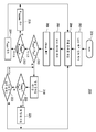
도 2는 본 발명에 따른 LED 전력 관리 방법의 흐름도이다. LED 램프는 다수의 LED 채널을 구비하며, 이들 각각은 다수의 LED 회로와 직렬인 채널 스위치를 갖는다. LED 회로들의 각각은 LED 소스와 병렬인 션트 스위치를 갖는다. 일 실시예에서, LED 램프는 도 1에 도시된 바와 같은 이중 채널 회로, 이중 LED 회로 램프이다. 다른 실시예에서, LED 램프는 도 3에 도시된 바와 같은 4중 채널 회로, 단일 LED 회로 램프이다.2 is a flowchart of an LED power management method according to the present invention. LED lamps have a plurality of LED channels, each of which has a channel switch in series with a plurality of LED circuits. Each of the LED circuits has a shunt switch in parallel with the LED source. In one embodiment, the LED lamp is a dual channel circuit, dual LED circuit lamp as shown in FIG. 1. In another embodiment, the LED lamp is a four channel circuit, single LED circuit lamp as shown in FIG.
도 2를 참조하면, 방법(200)은 201에서 시작되며, LED 램프에 대한 LED 램프 설정들을 초기화하는 단계(202), LED 램프 설정들로부터 LED 소스들의 각각에 대한 루멘 프랙션들을 계산하는 단계(204), 루멘 프랙션들로부터 션트 스위치들에 대한 듀티 사이클들을 계산하는 단계(206), 및 듀티 사이클들로부터 LED 램프에 대한 LED 램프 전자 장치 전력 손실(Ploss)를 계산하는 단계(208)를 포함한다. LED 램프 전자 장치 전력 손실(Ploss)은 LED 램프 전자 장치에서의 전력 손실을 설명하며, LED 소스들에서의 전력 손실을 포함하지 않는다.Referring to FIG. 2, the
방법(200)은 LED 램프 전자 장치 전력 손실(Ploss)이 LED 램프 전자 장치 전력 손실 한계(Plim)보다 작은지의 여부를 판정하는 단계(210)로 이어진다. LED 램프 전자 장치 전력 손실(Ploss)이 LED 램프 전자 장치 전력 손실 한계(Plim)보다 작지 않을 때, 채널 스위치 전력(Pmain)이 션트 스위치 전력(Pbypass)보다 작은지의 여부를 판정한다. 채널 스위치 전력(Pmain)이 션트 스위치 전력(Pbypass)보다 작지 않을 때, 채널 스위치 전력(Pmain)이 감소되며(214), 방법(200)은 갱신된 루멘 프랙션들을 계산하는 단계(204)로 이어질 수 있다. 채널 스위치 전력(Pmain)이 션트 스위치 전력(Pbypass)보다 작을 때, 션트 스위치 전력(Pbypass)이 감소되며(216), 방법(200)은 갱신된 루멘 프랙션들을 계산하는 단계(204)로 이어질 수 있다.The
LED 램프 전자 장치 전력 손실(Ploss)이 LED 램프 전자 장치 전력 손실 한계(Plim)보다 작을 때, 정상 동작이 이어질 수 있다(218). 일 실시예에서, LED 램프의 온도를 모니터링하여, 측정된 온도(Tmeas)가 온도 한계(Tlim)보다 작은지의 여부를 판정할 수 있다(220). 측정된 온도(Tmeas)가 온도 한계(Tlim)보다 작지 않은 경우, 딤 명령을 조정하여 LED 램프 광 출력을 줄일 수 있으며(221), 방법(200)은 디밍된 LED 램프에 대한 갱신된 루멘 프랙션들을 계산하는 단계(204)로 이어질 수 있다. 이 분야의 기술자들은 측정된 온도(Tmeas)가 특정 응용에 필요한 바와 같이 CRI 및/또는 컬러 온도를 변경함으로써 감소될 수도 있다는 것을 알 것이다. 측정 온도(Tmeas)가 온도 한계(Tlim)보다 작은 경우, 정상 동작이 이어질 수 있다(218). 일 실시예에서, 방법(200)은 사용자 입력 변경들을 모니터링하는 단계(222)로 이어질 수 있다. 사용자 입력 변경들이 존재하는 경우, 방법(200)은 새로운 사용자 입력들에 대한 갱신된 루멘 프랙션들을 계산하는 단계(204)로 이어질 수 있다. 사용자 입력 변경이 존재하지 않는 경우, 정상 동작이 이어질 수 있다(218). 이 분야의 기술자들은 온도 모니터링(220) 및/또는 사용자 입력 모니터링(222)이 특정 응용에 필요한 바에 따라 생략될 수 있다는 것을 알 것이다. 개별 LED 컬러, LED 램프 광 컬러, LED 램프 광 품질 등과 같은 추가 동작 파라미터들이 필요에 따라 모니터링될 수 있다.When the LED lamp electronics power loss P loss is less than the LED lamp electronics power loss limit P lim , normal operation may continue (218). In one embodiment, the temperature of the LED lamp may be monitored to determine whether the measured temperature T meas is less than the temperature limit T lim (220). If the measured temperature T meas is not less than the temperature limit T lim , the dim command can be adjusted to reduce the LED lamp light output (221) and the
LED 램프에 대한 LED 램프 설정들을 초기화하는 단계(202)는 컬러 설정, 딤 설정 등과 같은 LED 램프 설정들을 초기화하는 단계를 포함할 수 있다. 초기 값들은 제조자, 조명 설계자에 의해 사전 결정되거나, 이전 사용으로부터의 저장된 사용자 입력들일 수 있다.Initializing the LED lamp settings for the
듀티 사이클들로부터 LED 램프에 대한 LED 램프 전자 장치 전력 손실(Ploss)을 계산하는 단계(208)는 채널 스위치들, 션트 스위치들 등에 대한 개별 전력 손실들을 계산하고, 개별 전력 손실들을 합산하여 LED 램프에 대한 전체 LED 램프 전자 장치 전력 손실(Ploss)을 계산하는 단계를 포함할 수 있다.Computing the LED lamp electronics power loss (P loss ) for the LED lamp from the duty cycles (208) calculates individual power losses for the channel switches, shunt switches, and the like, and adds the individual power losses to the LED lamp. Computing the total LED lamp electronic device power loss (P loss ) for.
채널 스위치 전력(Pmain)을 줄이는 단계(214)는 하나 이상의 LED 채널을 통한 LED 채널 전류를 줄여, LED 램프를 디밍하고, 그리고/또는 하나 이상의 LED 채널의 이력 윈도우를 확장하여, 채널 스위치들의 스위칭 주파수를 줄이는 액션들을 포함할 수 있다. 이력 윈도우의 확장은 보다 낮은 주파수에서 LED 소스들을 통한 동일한 평균 전류를 유지한다. 그러나, 이것은 약간의 컬러 시프트를 유발할 수 있는데, 그 이유는 감소된 주파수에서의 파형이 LED 램프를 교정하는 데 사용되는 파형과 다를 수 있기 때문이다. 이 분야의 기술자들은 채널 스위치 전력(Pmain)의 감소량이 특정 응용에 필요한 바에 따라 선택될 수 있다는 것을 알 것이다.Reducing the channel
채널 스위치 전력(Pmain)을 줄이기 위해 취해지는 액션들은 상이한 순서 및 정도로 취해질 수 있다. LED 채널 전류 감소에 의한 디밍 및 이력 윈도우의 확장은 특정 응용에 필요한 바에 따라 개별적으로 또는 조합하여 사용될 수 있다. 일 실시예에서, 조명 설계자는 바람직한 액션들의 순서, 즉 하나 이상의 LED 채널을 통한 LED 채널 전류의 감소 또는 이력 윈도우의 확장이 먼저 발생할지를 지정할 수 있다. 다른 실시예에서, 바람직한 액션들의 순서는 제조자에 의해 미리 결정된다. 또 다른 실시예에서, 제1 액션은 제1 한계에 도달할 때까지 수행될 수 있으며, 제2 액션은 제2 한계에 도달할 때까지 수행될 수 있고, 이어서 다시 제1 액션이 수행될 수 있다. 예를 들어, LED 채널 전류는 광 출력이 제1 한계 이하일 때까지 감소될 수 있으며, 이어서 컬러가 제2 한계에 도달할 때까지 이력 윈도우가 확장될 수 있으며, 이어서 LED 채널 전류가 더 감소될 수 있다. 이 분야의 기술자들은 상이한 접근법들이 특정 응용에 적합하지 않을 수 있다는 것을 알 것이다. 예를 들어, 최소 광속이 요구되고, LED 램프가 이미 최소로 동작하고 있을 때, LED 램프의 디밍은 바람직하지 않을 수 있다. 다른 예에서, 일정 광 컬러가 요구될 때 이력 윈도우의 확장은 바람직하지 않을 수 있다.The actions taken to reduce the channel switch power P main may be taken in different orders and degrees. Dimming and extension of the hysteresis window by LED channel current reduction can be used individually or in combination as needed for a particular application. In one embodiment, the lighting designer may specify whether a desired sequence of actions occurs, namely, reduction of LED channel current through one or more LED channels or expansion of the history window first. In another embodiment, the order of the preferred actions is predetermined by the manufacturer. In yet another embodiment, the first action may be performed until the first limit is reached, the second action may be performed until the second limit is reached, and then the first action may be performed again. . For example, the LED channel current may be reduced until the light output is below the first limit, then the hysteresis window may be expanded until the color reaches the second limit, and then the LED channel current may be further reduced. have. Those skilled in the art will appreciate that different approaches may not be suitable for a particular application. For example, when a minimum luminous flux is required and the LED lamp is already operating at a minimum, dimming the LED lamp may be undesirable. In another example, the expansion of the history window may be undesirable when certain light colors are required.
션트 스위치 전력(Pbypass)을 줄이는 단계(216)는 하나 이상의 LED 채널을 통한 LED 채널 전류를 줄여 LED 램프를 디밍하고, 광 컬러를 변경하여 하나 이상의 LED 채널 내의 LED 소스들의 듀티 사이클들을 등화하고, 그리고/또는 컬러 렌더링 인덱스(CRI)를 변경하여 하나 이상의 LED 채널 내의 LED 소스들의 듀티 사이클들을 등화하는 단계를 포함할 수 있다. 광 컬러를 변경하여 각각의 LED 채널 내의 LED 소소들의 듀티 사이클들을 등화하는 것은 LED 채널들을 통한 전류의 감소를 허가하여, 각각의 채널 내의 LED 소스들의 듀티 사이클들을 최대화한다. 컬러 렌더링 인덱스(CRI)를 변경하여 각각의 LED 채널 내의 LED 소스들의 듀티 사이클들을 등화하는 것은 LED 채널들을 통한 전류의 감소를 허가하여, LED 램프에 대한 동일한 컬러 포인트 및 강도를 유지하면서 각각의 LED 채널 내의 LED 소스들의 듀티 사이클들을 최대화한다. 이 분야의 전문가들은 션트 스위치 전력(Pbypass)의 감소량이 특정 응용에 필요한 바에 따라 선택될 수 있다는 것을 알 것이다.Reducing the shunt switch power (P bypass ) 216 reduces the LED channel current through one or more LED channels to dimm the LED lamp, change the light color to equalize the duty cycles of the LED sources in the one or more LED channels, And / or changing the color rendering index (CRI) to equalize the duty cycles of the LED sources in the one or more LED channels. Equalizing the duty cycles of the LED sources in each LED channel by changing the light color permits a reduction in current through the LED channels, maximizing the duty cycles of the LED sources in each channel. Equalizing the duty cycles of the LED sources within each LED channel by changing the color rendering index (CRI) permits a reduction in current through the LED channels, keeping each LED channel while maintaining the same color point and intensity for the LED lamp. Maximize the duty cycles of the LED sources within. Experts in this field will know that the amount of reduction in shunt switch power (P bypass ) can be selected as needed for a particular application.
션트 스위치 전력(Pbypass)을 줄이기 위해 취해지는 액션들은 상이한 순서 및 정도로 취해질 수 있다. LED 채널 전류 감소에 의한 디밍, 스위칭 전류의 감소, 광 컬러의 변경 및/또는 컬러 렌더링 인덱스(CRI)의 변경은 특정 응용에 필요한 바에 따라 개별적으로 또는 조합하여 사용될 수 있다. 일 실시예에서, 조명 설계자는 바람직한 액션들의 순서, 즉 LED 채널 전류의 감소, 스위칭 주파수 감소, 광 컬러 변경 또는 컬러 렌더링 인덱스(CRI)의 변경이 먼저 발생할지를 지정할 수 있다. 다른 실시예에서, 바람직한 액션들의 순서는 제조자에 의해 사전 결정될 수 있다. 또 다른 실시예에서, 제1 액션은 제1 한계에 도달할 때까지 수행될 수 있고, 이어서 제2 액션은 제2 한계에 도달할 때까지 수행될 수 있으며, 이어서 제1 액션이 다시 수행될 수 있다. 예를 들어, LED 채널 전류는 광 출력이 제1 한계 이하일 때까지 감소될 수 있고, 이어서 광 컬러는 컬러가 제2 한계에 도달할 때까지 변경될 수 있으며, 이어서 LED 채널 전류가 더 감소될 수 있다. 다양한 액션들이 원하는 임의의 순서 및 임의의 정도로 수행될 수 있다. 이 분야의 기술자들은 상이한 접근법들이 특정 응용에 적합하지 않을 수 있다는 것을 알 것이다. 예컨대, 최소 광속이 필요하고, LED 램프가 이미 최소로 동작하고 있을 때 LED 램프의 디밍은 바람직하지 않을 수 있다. 다른 예에서, 일정한 광 컬러가 필요할 때 광 컬러의 변경은 바람직하지 않을 수 있다. 또 다른 예에서, 소정의 컬러 외관이 필요할 때 컬러 렌더링 인덱스(CRI)의 변경은 바람직하지 않을 수 있다.The actions taken to reduce the shunt switch power P bypass may be taken in different orders and degrees. Dimming by reducing LED channel current, reducing switching current, changing color of light and / or changing color rendering index (CRI) can be used individually or in combination as needed for a particular application. In one embodiment, the lighting designer can specify whether the order of the desired actions, namely a decrease in LED channel current, a decrease in switching frequency, a change in light color or a change in color rendering index (CRI), will occur first. In other embodiments, the order of the desired actions may be predetermined by the manufacturer. In another embodiment, the first action may be performed until the first limit is reached, then the second action may be performed until the second limit is reached, and then the first action may be performed again. have. For example, the LED channel current can be reduced until the light output is below the first limit, then the light color can be changed until the color reaches the second limit, and then the LED channel current can be further reduced. have. Various actions may be performed in any order and to any degree desired. Those skilled in the art will appreciate that different approaches may not be suitable for a particular application. For example, dimming of an LED lamp may be undesirable when a minimum luminous flux is required and the LED lamp is already operating at a minimum. In another example, changing the light color may be undesirable when a constant light color is needed. In another example, changing the color rendering index (CRI) may be undesirable when some color appearance is needed.
LED 램프 전자 장치 전력 손실(Ploss)이 LED 램프 전자 장치 전력 손실 한계(Plim)보다 작을 때의 정상 동작(218) 동안, 사용자 입력들 및 LED 램프의 동작 파라미터들이 모니터링될 수 있다. 측정된 LED 램프의 온도(Tmeas)를 모니터링하여, 측정된 온도(Tmeas)가 온도 한계(Tlim)보다 작은지의 여부를 판정하는 단계(220)는 LED 램프에 열적으로 결합되는 서미스터, 음의 온도 계수(NTC) 서미스터, 열전쌍 등과 같은 온도 센서로 측정된 LED 램프의 온도(Tmeas)를 모니터링하는 단계를 포함할 수 있다. 측정 온도(Tmeas)는 온도 센서 위치 열 결합에 따라 LED 램프 전자 장치에서의 전력 손실 및/또는 LED 소스들에서의 전력 손실을 설명할 수 있다. 다른 실시예에서, 측정된 LED 램프의 온도(Tmeas)를 모니터링하는 단계는 마이크로컨트롤러에서 동작 파라미터들로부터 측정 온도(Tmeas)를 추정하는 단계를 포함할 수 있다. 측정 온도(Tmeas)가 온도 한계(Tlim)보다 작지 않을 때 딤 명령을 조정하는 단계(221)는 측정 온도(Tmeas)가 온도 한계(Tlim)를 초과하는 양에 비례하여 딤 명령을 더 어두운 LED 램프 설정으로 조정하는 단계를 포함할 수 있다. 사용자 입력 변경들을 모니터링하는 단계(222)는 새로운 LED 램프 설정에 대해 컬러 명령 신호들, 딤 명령 신호들 등의 변경들과 같은 사용자 입력 변경들을 모니터링하는 단계를 포함할 수 있다. 루멘 프랙션들은 새로운 LED 램프 설정에 대한 더 낮은 온도 및/또는 새로운 사용자 입력들을 생성하기 위해 디밍된 LED 램프 설정들에 대해 계산될 수 있다(204).During
이 분야의 기술자들은 특정 응용에 필요한 바에 따라 LED 램프 전자 장치 전력 손실(Ploss)이 LED 램프 전자 장치 전력 손실 한계(Plim) 이상일 때에도 LED 램프의 동작 파라미터들이 모니터링될 수 있다는 것을 알 것이다. 예를 들어, 채널 스위치 전력(Pmain)을 줄이거나(214) 션트 스위치 전력(Pbypass)을 줄이는(216) 교정 수단은 LED 램프 전자 장치 전력 손실(Ploss)이 LED 램프 전자 장치 전력 손실 한계(Plim)보다 작은 것을 보장하기에 불충분할 수 있다. 측정된 LED 램프의 온도(Tmeas)가 모니터링될 수 있고, 측정된 온도(Tmeas)가 온도 한계(Tlim)보다 작지 않을 때, 그리고 교정 수단이 LED 램프 전자 장치 전력 손실(Ploss)을 LED 램프 전자 장치 전력 손실 한계(Plim) 아래로 줄이기에 충분하지 않을 때 딤 명령이 조정될 수 있다. 일 실시예에서, 마이크로컨트롤러가 교정 수단이 불충분한 것으로 결정할 때 LED 램프의 동작 파라미터들이 모니터링될 수 있다. 다른 실시예에서, 채널 스위치 전력(Pmain)을 줄이고(214), 그리고/또는 션트 스위치 전력(Pbypass)을 줄이는(216) 교정 수단이 LED 램프 전자 장치 전력 손실(Ploss)을 LED 램프 전자 장치 전력 손실 한계(Plim) 아래로 줄이지 못하고 소정 횟수 수행된 때 LED 램프의 동작 파라미터들이 모니터링될 수 있다.Those skilled in the art will appreciate that the operating parameters of the LED lamp can be monitored even when the LED lamp electronics power loss (P loss ) is above the LED lamp electronics power loss limit (P lim ) as required for a particular application. For example, the means for reducing channel switch power P main (214) or reducing shunt switch power (P bypass ) (216) means that the LED lamp electronics power loss (P loss ) is the LED lamp electronics power loss limit. It may be insufficient to ensure that it is less than P lim . The temperature of the measurement LED lamp (T meas) and can be monitored, the temperature limit of measurement temperature (T meas) when it is smaller than (T lim), and the correction means is an LED lamp electronics power loss (P loss) The dim command can be adjusted when it is not enough to reduce below the LED lamp electronics power loss limit (P lim ). In one embodiment, operating parameters of the LED lamp can be monitored when the microcontroller determines that the calibration means is insufficient. In another embodiment, the calibrating means for reducing channel switch power P main (214) and / or reducing shunt switch power (P bypass ) (216) provides for LED lamp electronics power loss (P loss ). Operating parameters of the LED lamps can be monitored when a certain number of times have been performed without reducing below the device power loss limit P lim .
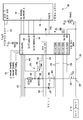
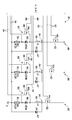
동일한 요소들이 도 1과 동일한 참조 번호들을 공유하는 도 3은 본 발명에 따른 LED 램프 전력 관리 시스템의 다른 실시예의 개략도이다. 이 예에서, LED 램프는 4중 채널 회로, 단일 LED 회로 램프이며, 즉 LED 램프는 LED 채널당 하나의 션트된 LED 회로를 갖는 4개의 LED 채널을 구비한다. LED 채널들의 각각에 상이한 컬러 LED 소스가 제공될 수 있으며, 따라서 LED 컬러들의 각각에 대해 전류가 제어될 수 있다. 특정 컬러가 필요하지 않을 때 LED 채널을 통한 전류가 LED 채널에 대한 채널 스위치를 이용하여 턴오프될 수 있으므로, 션트 스위치들에 대한 전력 손실들이 최소화될 수 있다.3, in which like elements share the same reference numerals as in FIG. 1, is a schematic diagram of another embodiment of an LED lamp power management system according to the invention. In this example, the LED lamp is a four channel circuit, a single LED circuit lamp, ie the LED lamp has four LED channels with one shunted LED circuit per LED channel. A different color LED source can be provided for each of the LED channels, so that the current can be controlled for each of the LED colors. Since no current through the LED channel can be turned off using the channel switch for the LED channel when no specific color is needed, power losses for the shunt switches can be minimized.
전력 관리 시스템을 이용하는 LED 램프(30)는 4개의 LED 채널(60)에 대한 전력을 제어하는 ASIC 이력 제어(50)에 동작 가능하게 접속되는 마이크로컨트롤러(40)를 구비하는 LED 제어기(58)를 포함한다. 각각의 LED 채널(60)은 전압과 공통 사이에 직렬로 접속되는 채널 스위치(62) 및 LED 회로(64)를 구비한다. 각각의 채널 스위치(62)는 LED 채널(60)을 통한 전류 흐름을 제어하기 위해 ASIC 이력 제어(50)로부터 채널 스위치 제어 신호(63)를 수신한다. 이 예에서, 각각의 LED 회로(64)는 션트 스위치(68)와 직렬인 인덕터(66)와 병렬인 다이오드(67)를 포함한다. 션트 스위치들(68)의 각각은 ASIC 이력 제어(50)로부터 션트 스위치 제어 신호(69)를 수신하며, LED 소스(80)에 병렬로 접속된다. 션트 스위치(68)는 그의 관련 LED 소스 주위의 채널 전류를 단락시켜 관련 LED 소스의 광 출력을 제어한다. 이 예에서, 기본 전자 토폴로지는 이력 벅 컨버터이다. 각각의 LED 채널(60)에 대한 인덕터(66)는 그 LED 채널(60) 내의 특정 LED(60)에 대한 원하는 스위칭 주파수를 제공하는 크기를 가질 수 있다. 일 실시예에서, LED 채널들(60)의 각각 내의 LED 소스들(80)은 상이한 컬러의 광을 생성할 수 있다.
동작에 있어서, 사용자는 마이크로컨트롤러(40)에 사용자 입력 신호들(42)을 제공하며, 마이크로컨트롤러는 HS 인에이블 신호들(46) 및 LS PWM 신호들(48)을 생성한다. ASIC 이력 제어(50)는 HS 인에이블 신호들(46) 및 LS PWM 신호들(48)을 수신하고, 채널 스위치 제어 신호들(63) 및 션트 스위치 제어 신호들(69)을 생성한다. LED 제어기(58)는 채널 스위치 제어 신호들(63) 및 션트 스위치 제어 신호들(69)을 생성함에 있어서 위의 도 2와 관련하여 설명된 바와 같은 LED 전력 관리 방법을 구현할 수 있다. 도 3을 참조하면, 채널 스위치 제어 신호(63)가 채널 스위치들(62)의 각각에 제공되어, LED 채널(60)을 통한 전류 흐름을 제어하며, 션트 스위치 제어 신호(69)가 션트 스위치들(68)의 각각에 제공되어 관련 LED의 광 출력을 제어한다.In operation, a user provides user input signals 42 to
일 실시예에서, 각각의 LED 채널(60)에 대한 인덕터(66)는 둘 이상의 인덕터를 포함하며, 인덕터들 중 하나는 하이 전류에서 포화되는 크기를 갖는다. 전류는 최적 컬러 및 CRI에서 백색광을 생성하는 설계 동작 포인트에서의 정상 동작 동안에 하이이며, 따라서 각각의 LED 채널(60) 내의 하나의 인덕터는 정상적으로 포화된다. 설계 동작 포인트와 다른 컬러 및/또는 CRI에서의 동작과 같이 LED 채널(60) 내의 전류가 로우일 때, 각각의 LED 채널(60) 내의 하나의 포화된 인덕터는 비포화 상태가 된다. 이것은 인덕터(66)의 전체 인덕턴스를 증가시키고, LED 채널(60)에 대한 스위칭 주파수를 줄인다. 각각의 LED 채널(60)에 대한 인덕터(66)의 둘 이상의 인덕터는 스위칭 주파수를 타당한 범위 내로 계속 유지하면서 이력 윈도우가 LED 채널(60)을 통한 전류 레벨의 일정한 퍼센트가 되게 선택될 수 있도록 선택되어야 한다. 예를 들어, 전류가 1/10로 낮아지고, 이력 윈도우를 계속 평균 전류의 10%로 유지하는 것이 바람직한 경우, 포화 가능한 인덕터가 사용되지 않는 경우에 스위칭 주파수는 10배 상승할 것이다. 그러나, 비포화 인덕터의 9배 값을 갖는 포화 가능한 인덕터를 사용함으로써, 전체 인덕턴스는 (인덕터가 비포화 상태가 될 때) 로우 전류 레벨들에서 최초 값의 10배로 증가할 것이다. 이것은 스위칭 주파수가 필요에 따라 변경되지 않는 것을 가능하게 한다.In one embodiment, the
본 명세서에서 본 발명의 실시예들은 현재 바람직한 것으로 간주되지만, 본 발명의 범위로부터 벗어나지 않고 다양한 변경들 및 변형들이 이루어질 수 있다. 본 발명의 범위는 첨부된 청구항에서 지시되며, 균등물들의 의미 및 범위 내에 있는 모든 변경들은 그 안에 포함되는 것을 의도한다.While embodiments of the present invention are considered to be presently preferred herein, various changes and modifications may be made without departing from the scope of the present invention. The scope of the invention is indicated in the appended claims, and all changes which come within the meaning and range of equivalency are intended to be embraced therein.
Claims (21)
상기 LED 제어기(58)에 동작 가능하게 접속되는 복수의 LED 채널(60) - 상기 복수의 LED 채널(60)의 각각은 적어도 하나의 션트(shunt)된 LED 회로(83)와 직렬인 채널 스위치(62)를 구비하고, 상기 션트된 LED 회로(83)는 LED 소스(80)와 병렬인 션트 스위치(68)를 구비함 -
을 포함하고,
상기 LED 제어기(58)는 LED 램프 전자 회로 전력 손실(LED lamp electronics power loss)(Ploss)이 LED 램프 전자 회로 전력 손실 한계(Plim)를 초과할 때 상기 채널 스위치(62) 및 상기 션트 스위치(68) 중 하나에서의 전력 손실을 줄이는 LED 램프.LED controller 58; And
A plurality of LED channels 60 operatively connected to the LED controller 58, each of the plurality of LED channels 60 being a channel switch in series with at least one shunted LED circuit 83; 62, wherein the shunted LED circuit 83 has a shunt switch 68 in parallel with the LED source 80.
Including,
The LED controller 58 includes the channel switch 62 and the shunt switch when an LED lamp electronics power loss P loss exceeds an LED lamp electronics circuit power loss limit P lim . LED lamp to reduce power loss in one of 68.
복수의 LED 채널을 구비하는 LED 램프를 제공하는 단계 - 상기 복수의 LED 채널의 각각은 적어도 하나의 션트된 LED 회로와 직렬인 채널 스위치를 구비하고, 상기 션트된 LED 회로는 LED 소스와 병렬인 션트 스위치를 구비함 - ;
상기 LED 램프에 대한 LED 램프 설정들을 초기화하는 단계(202);
상기 LED 램프 설정들로부터 상기 LED 소스들의 각각에 대한 루멘 프랙션들(lumen fractions)을 계산하는 단계(204);
상기 루멘 프랙션들로부터 상기 션트 스위치들에 대한 듀티 사이클들을 계산하는 단계(206);
상기 듀티 사이클들로부터 상기 LED 램프에 대한 LED 램프 전자 장치 전력 손실(Ploss)을 계산하는 단계(208);
상기 LED 램프 전자 장치 전력 손실(Ploss)이 LED 램프 전자 장치 전력 손실 한계(Plim)보다 작은지의 여부를 판정하는 단계(210);
상기 LED 램프 전자 장치 전력 손실(Ploss)이 상기 LED 램프 전자 장치 전력 손실 한계(Plim)보다 작지 않을 때, 상기 채널 스위치들에 대한 채널 스위치 전력(Pmain)이 상기 션트 스위치들에 대한 션트 스위치 전력(Pbypass)보다 작은지의 여부를 판정하는 단계;
상기 채널 스위치 전력(Pmain)이 상기 션트 스위치 전력(Pbypass)보다 작지 않을 때, 상기 채널 스위치 전력(Pmain)을 줄이는 단계(214); 및
상기 채널 스위치 전력(Pmain)이 상기 션트 스위치 전력(Pbypass)보다 작을 때, 상기 션트 스위치 전력(Pbypass)을 줄이는 단계(216)
를 포함하는 방법.As an LED lamp power management method,
Providing an LED lamp having a plurality of LED channels, each of the plurality of LED channels having a channel switch in series with at least one shunted LED circuit, the shunted LED circuit being in parallel with an LED source With a switch;
Initializing (202) LED lamp settings for the LED lamp;
Calculating (204) lumen fractions for each of the LED sources from the LED lamp settings;
Calculating (206) duty cycles for the shunt switches from the lumen fractions;
Calculating (208) an LED lamp electronics power loss (P loss ) for the LED lamp from the duty cycles;
Determining (210) whether the LED lamp electronics power loss (P loss ) is less than an LED lamp electronics power loss limit (P lim );
When the LED lamp electronics power loss P loss is not less than the LED lamp electronics power loss limit P lim , the channel switch power P main for the channel switches is the shunt for the shunt switches. Determining whether it is less than the switch power P bypass ;
The channel switch power (P main), wherein the shunt switch power (P bypass) to reduce step 214 a, the channel switch power (P main), when not less than; And
When the channel switch power (P main) is less than the shunt switch power (P bypass), the step of reducing the shunt switch power (P bypass) (216)
How to include.
상기 LED 램프의 측정 온도(Tmeas)가 온도 한계(Tlim)보다 작은지의 여부를 판정하는 단계(220); 및
상기 측정 온도(Tmeas)가 상기 온도 한계(Tlim)보다 작지 않을 때 상기 LED 램프에 대한 딤 명령을 조정하는 단계(221)
를 더 포함하는 방법.The method of claim 11,
Determining (220) whether the measured temperature T meas of the LED lamp is less than a temperature limit T lim ; And
Adjusting the dim command for the LED lamp when the measured temperature T meas is not less than the temperature limit T lim 221
How to include more.
복수의 LED 채널을 구비하는 LED 램프 - 상기 복수의 LED 채널의 각각은 적어도 하나의 션트된 LED 회로와 직렬인 채널 스위치를 구비하고, 상기 션트된 LED 회로는 LED 소스와 병렬인 션트 스위치를 구비함 - ;
상기 LED 램프에 대한 LED 램프 설정들을 초기화하기 위한 수단;
상기 LED 램프 설정들로부터 상기 LED 소스들의 각각에 대한 루멘 프랙션들을 계산하기 위한 수단;
상기 루멘 프랙션들로부터 상기 션트 스위치들에 대한 듀티 사이클들을 계산하기 위한 수단;
상기 듀티 사이클들로부터 상기 LED 램프에 대한 LED 램프 전자 장치 전력 손실(Ploss)을 계산하기 위한 수단;
상기 LED 램프 전자 장치 전력 손실(Ploss)이 LED 램프 전자 장치 전력 손실 한계(Plim)보다 작은지의 여부를 판정하기 위한 수단;
상기 LED 램프 전자 장치 전력 손실(Ploss)이 상기 LED 램프 전자 장치 전력 손실 한계(Plim)보다 작지 않을 때, 상기 채널 스위치들에 대한 채널 스위치 전력(Pmain)이 상기 션트 스위치들에 대한 션트 스위치 전력(Pbypass)보다 작은지의 여부를 판정하기 위한 수단;
상기 채널 스위치 전력(Pmain)이 상기 션트 스위치 전력(Pbypass)보다 작지 않을 때, 상기 채널 스위치 전력(Pmain)을 줄이기 위한 수단; 및
상기 채널 스위치 전력(Pmain)이 상기 션트 스위치 전력(Pbypass)보다 작을 때, 상기 션트 스위치 전력(Pbypass)을 줄이기 위한 수단
을 포함하는 LED 램프 전력 관리 시스템.LED lamp power management system,
LED lamps having a plurality of LED channels, each of the plurality of LED channels having a channel switch in series with at least one shunted LED circuit, the shunted LED circuit having a shunt switch in parallel with the LED source -;
Means for initializing LED lamp settings for the LED lamp;
Means for calculating lumen fractions for each of the LED sources from the LED lamp settings;
Means for calculating duty cycles for the shunt switches from the lumen fractions;
Means for calculating an LED lamp electronics power loss (P loss ) for the LED lamp from the duty cycles;
Means for determining whether the LED lamp electronics power loss P loss is less than an LED lamp electronics power loss limit P lim ;
When the LED lamp electronics power loss P loss is not less than the LED lamp electronics power loss limit P lim , the channel switch power P main for the channel switches is the shunt for the shunt switches. Means for determining whether it is less than the switch power P bypass ;
When the channel switch power (P main) is not less than the shunt switch power (P bypass), means for reducing the channel switch power (P main); And
When the channel switch power (P main) is less than the shunt switch power (P bypass), means for reducing the shunt switch power (P bypass)
LED lamp power management system comprising a.
Applications Claiming Priority (2)
| Application Number | Priority Date | Filing Date | Title |
|---|---|---|---|
| US1212707P | 2007-12-07 | 2007-12-07 | |
| US61/012,127 | 2007-12-07 |
Publications (1)
| Publication Number | Publication Date |
|---|---|
| KR20100096231A true KR20100096231A (en) | 2010-09-01 |
Family
ID=40627111
Family Applications (1)
| Application Number | Title | Priority Date | Filing Date |
|---|---|---|---|
| KR1020107015021A KR20100096231A (en) | 2007-12-07 | 2008-12-02 | Led lamp power management system and method |
Country Status (8)
| Country | Link |
|---|---|
| US (1) | US8400071B2 (en) |
| EP (1) | EP2220914A2 (en) |
| JP (1) | JP5335808B2 (en) |
| KR (1) | KR20100096231A (en) |
| CN (1) | CN101889477A (en) |
| BR (1) | BRPI0820090A2 (en) |
| RU (1) | RU2481752C2 (en) |
| WO (1) | WO2009072058A2 (en) |
Families Citing this family (60)
| Publication number | Priority date | Publication date | Assignee | Title |
|---|---|---|---|---|
| US20050259424A1 (en) | 2004-05-18 | 2005-11-24 | Zampini Thomas L Ii | Collimating and controlling light produced by light emitting diodes |
| US7766511B2 (en) | 2006-04-24 | 2010-08-03 | Integrated Illumination Systems | LED light fixture |
| US7729941B2 (en) | 2006-11-17 | 2010-06-01 | Integrated Illumination Systems, Inc. | Apparatus and method of using lighting systems to enhance brand recognition |
| US8013538B2 (en) | 2007-01-26 | 2011-09-06 | Integrated Illumination Systems, Inc. | TRI-light |
| US8742686B2 (en) | 2007-09-24 | 2014-06-03 | Integrated Illumination Systems, Inc. | Systems and methods for providing an OEM level networked lighting system |
| US8255487B2 (en) | 2008-05-16 | 2012-08-28 | Integrated Illumination Systems, Inc. | Systems and methods for communicating in a lighting network |
| US8093821B2 (en) * | 2009-02-05 | 2012-01-10 | The Hong Kong Polytechnic University | Driving method for improving luminous efficacy of a light emitting diode |
| US8585245B2 (en) | 2009-04-23 | 2013-11-19 | Integrated Illumination Systems, Inc. | Systems and methods for sealing a lighting fixture |
| TWI538553B (en) * | 2009-08-25 | 2016-06-11 | 皇家飛利浦電子股份有限公司 | Multichannel lighting unit and driver for supplying current to light sources in multichannel lighting unit |
| CA2772759C (en) * | 2009-09-04 | 2017-02-28 | Koninklijke Philips Electronics N.V. | Light emitting diode circuit |
| DE102010008275B4 (en) | 2010-02-17 | 2019-10-10 | Continental Automotive Gmbh | Device for powering several LED units |
| DE102010003136A1 (en) * | 2010-03-23 | 2011-09-29 | Osram Gesellschaft mit beschränkter Haftung | Circuit arrangement and method for operating at least one LED |
| DE102010003244A1 (en) * | 2010-03-25 | 2011-09-29 | Osram Gesellschaft mit beschränkter Haftung | Method and circuit arrangement for operating a plurality of LEDs |
| US9554433B2 (en) * | 2010-04-09 | 2017-01-24 | Eldolab Holding B.V. | Driver system for driving a plurality of LED's |
| US20120062120A1 (en) * | 2010-09-14 | 2012-03-15 | Riesebosch Scott A | Thermal foldback circuit with dimmer monitor |
| US10178723B2 (en) | 2011-06-03 | 2019-01-08 | Cree, Inc. | Systems and methods for controlling solid state lighting devices and lighting apparatus incorporating such systems and/or methods |
| US8644699B2 (en) | 2011-02-17 | 2014-02-04 | Nokia Corporation | Method and apparatus for light emitting diode control |
| US9066381B2 (en) | 2011-03-16 | 2015-06-23 | Integrated Illumination Systems, Inc. | System and method for low level dimming |
| US8823289B2 (en) * | 2011-03-24 | 2014-09-02 | Cirrus Logic, Inc. | Color coordination of electronic light sources with dimming and temperature responsiveness |
| US8939604B2 (en) | 2011-03-25 | 2015-01-27 | Arkalumen Inc. | Modular LED strip lighting apparatus |
| US9967940B2 (en) | 2011-05-05 | 2018-05-08 | Integrated Illumination Systems, Inc. | Systems and methods for active thermal management |
| US9060400B2 (en) * | 2011-07-12 | 2015-06-16 | Arkalumen Inc. | Control apparatus incorporating a voltage converter for controlling lighting apparatus |
| US11917740B2 (en) | 2011-07-26 | 2024-02-27 | Hunter Industries, Inc. | Systems and methods for providing power and data to devices |
| US20150237700A1 (en) | 2011-07-26 | 2015-08-20 | Hunter Industries, Inc. | Systems and methods to control color and brightness of lighting devices |
| US10874003B2 (en) | 2011-07-26 | 2020-12-22 | Hunter Industries, Inc. | Systems and methods for providing power and data to devices |
| US9521725B2 (en) | 2011-07-26 | 2016-12-13 | Hunter Industries, Inc. | Systems and methods for providing power and data to lighting devices |
| US8710770B2 (en) | 2011-07-26 | 2014-04-29 | Hunter Industries, Inc. | Systems and methods for providing power and data to lighting devices |
| US9609720B2 (en) | 2011-07-26 | 2017-03-28 | Hunter Industries, Inc. | Systems and methods for providing power and data to lighting devices |
| RU2597326C2 (en) | 2011-08-08 | 2016-09-10 | Конинклейке Филипс Н.В. | Light-emitting diode (led) light source with reduced flickering |
| US8581519B2 (en) * | 2011-08-25 | 2013-11-12 | Hong Kong Applied Science & Technology Research Institute Co., Ltd. | Current-switching LED driver using DAC to ramp bypass currents to accelerate switching speed and reduce ripple |
| EP2575411B1 (en) * | 2011-09-27 | 2018-07-25 | Infineon Technologies AG | LED driver with compensation of thermally induced colour drift |
| US8736186B2 (en) | 2011-11-14 | 2014-05-27 | Cree, Inc. | Solid state lighting switches and fixtures providing selectively linked dimming and color control and methods of operating |
| US10117295B2 (en) | 2013-01-24 | 2018-10-30 | Cree, Inc. | LED lighting apparatus for use with AC-output lighting ballasts |
| US9871404B2 (en) * | 2011-12-12 | 2018-01-16 | Cree, Inc. | Emergency lighting devices with LED strings |
| US8901831B2 (en) | 2012-05-07 | 2014-12-02 | Lighting Science Group Corporation | Constant current pulse-width modulation lighting system and associated methods |
| US20130293124A1 (en) * | 2012-05-07 | 2013-11-07 | Lighting Science Group Corporation | System for generating light having a constant color temperature and associated methods |
| US8894437B2 (en) | 2012-07-19 | 2014-11-25 | Integrated Illumination Systems, Inc. | Systems and methods for connector enabling vertical removal |
| JP6389460B2 (en) * | 2012-08-07 | 2018-09-12 | フィリップス ライティング ホールディング ビー ヴィ | Power supply |
| CN102932988A (en) * | 2012-09-24 | 2013-02-13 | 王习之 | Method and circuit for increasing light emitting diode (LED) light source module color rendering index with low cost |
| US9379578B2 (en) | 2012-11-19 | 2016-06-28 | Integrated Illumination Systems, Inc. | Systems and methods for multi-state power management |
| US9420665B2 (en) | 2012-12-28 | 2016-08-16 | Integration Illumination Systems, Inc. | Systems and methods for continuous adjustment of reference signal to control chip |
| US9485814B2 (en) | 2013-01-04 | 2016-11-01 | Integrated Illumination Systems, Inc. | Systems and methods for a hysteresis based driver using a LED as a voltage reference |
| US10231300B2 (en) | 2013-01-15 | 2019-03-12 | Cree, Inc. | Systems and methods for controlling solid state lighting during dimming and lighting apparatus incorporating such systems and/or methods |
| US9345091B2 (en) * | 2013-02-08 | 2016-05-17 | Cree, Inc. | Light emitting device (LED) light fixture control systems and related methods |
| US9788388B2 (en) * | 2013-11-21 | 2017-10-10 | Barco N.V. | Method for controlling illumination for an optical display system |
| WO2015181132A1 (en) | 2014-05-30 | 2015-12-03 | Koninklijke Philips N.V. | Led lighting circuit fed by current source |
| JP2016071981A (en) * | 2014-09-29 | 2016-05-09 | 三菱電機株式会社 | Light source control device and light source control method |
| US10225904B2 (en) | 2015-05-05 | 2019-03-05 | Arkalumen, Inc. | Method and apparatus for controlling a lighting module based on a constant current level from a power source |
| US10568180B2 (en) | 2015-05-05 | 2020-02-18 | Arkalumen Inc. | Method and apparatus for controlling a lighting module having a plurality of LED groups |
| US9992836B2 (en) | 2015-05-05 | 2018-06-05 | Arkawmen Inc. | Method, system and apparatus for activating a lighting module using a buffer load module |
| US9992829B2 (en) | 2015-05-05 | 2018-06-05 | Arkalumen Inc. | Control apparatus and system for coupling a lighting module to a constant current DC driver |
| US10918030B2 (en) | 2015-05-26 | 2021-02-16 | Hunter Industries, Inc. | Decoder systems and methods for irrigation control |
| US10228711B2 (en) | 2015-05-26 | 2019-03-12 | Hunter Industries, Inc. | Decoder systems and methods for irrigation control |
| US10060599B2 (en) | 2015-05-29 | 2018-08-28 | Integrated Illumination Systems, Inc. | Systems, methods and apparatus for programmable light fixtures |
| US10030844B2 (en) | 2015-05-29 | 2018-07-24 | Integrated Illumination Systems, Inc. | Systems, methods and apparatus for illumination using asymmetrical optics |
| KR101632536B1 (en) | 2015-06-30 | 2016-06-22 | 주식회사 케이알이엠에스 | Communication method using DC Power LED Control |
| CN105704864A (en) * | 2016-04-13 | 2016-06-22 | 杭州聪普智能科技有限公司 | Atmosphere illuminating system and method based on music contents |
| CN106602905B (en) * | 2017-03-01 | 2023-06-13 | 英飞特电子(杭州)股份有限公司 | LED driving circuit |
| CN106787854B (en) * | 2017-03-01 | 2023-06-13 | 英飞特电子(杭州)股份有限公司 | LED driving circuit |
| US10801714B1 (en) | 2019-10-03 | 2020-10-13 | CarJamz, Inc. | Lighting device |
Family Cites Families (10)
| Publication number | Priority date | Publication date | Assignee | Title |
|---|---|---|---|---|
| US6925067B2 (en) * | 1999-04-23 | 2005-08-02 | Qualcomm, Incorporated | Configuration of overhead channels in a mixed bandwidth system |
| JP4527316B2 (en) * | 2001-05-18 | 2010-08-18 | ティーオーエー株式会社 | Light emitting diode lighting circuit and light emitting diode lighting method |
| ES2933481T3 (en) | 2002-12-19 | 2023-02-09 | Signify Holding Bv | led driver |
| US6956338B1 (en) | 2003-08-12 | 2005-10-18 | Masonware Partners, Llc | Analog control of light sources |
| JP4241487B2 (en) * | 2004-04-20 | 2009-03-18 | ソニー株式会社 | LED driving device, backlight light source device, and color liquid crystal display device |
| JP4509731B2 (en) * | 2004-10-13 | 2010-07-21 | 株式会社小糸製作所 | Lighting control circuit for vehicular lamp |
| JP4707400B2 (en) * | 2005-01-25 | 2011-06-22 | ローム株式会社 | Power supply device, light emitting device and display device |
| US7081722B1 (en) * | 2005-02-04 | 2006-07-25 | Kimlong Huynh | Light emitting diode multiphase driver circuit and method |
| JP4199202B2 (en) * | 2005-02-14 | 2008-12-17 | 星和電機株式会社 | Power supply device and lighting device |
| JP2008535279A (en) * | 2005-04-08 | 2008-08-28 | ワルト ホッフ ツゥー ホールディング ベスローテン フェンノートシャップ | Method and apparatus for operating high power LED group |
-
2008
- 2008-12-02 KR KR1020107015021A patent/KR20100096231A/en active IP Right Grant
- 2008-12-02 JP JP2010536566A patent/JP5335808B2/en active Active
- 2008-12-02 WO PCT/IB2008/055036 patent/WO2009072058A2/en active Application Filing
- 2008-12-02 RU RU2010128104/07A patent/RU2481752C2/en not_active IP Right Cessation
- 2008-12-02 BR BRPI0820090-4A patent/BRPI0820090A2/en not_active IP Right Cessation
- 2008-12-02 EP EP08858115A patent/EP2220914A2/en not_active Withdrawn
- 2008-12-02 CN CN2008801193095A patent/CN101889477A/en active Pending
- 2008-12-02 US US12/746,540 patent/US8400071B2/en active Active
Also Published As
| Publication number | Publication date |
|---|---|
| CN101889477A (en) | 2010-11-17 |
| BRPI0820090A2 (en) | 2015-06-30 |
| EP2220914A2 (en) | 2010-08-25 |
| WO2009072058A2 (en) | 2009-06-11 |
| WO2009072058A3 (en) | 2010-03-25 |
| RU2481752C2 (en) | 2013-05-10 |
| RU2010128104A (en) | 2012-01-20 |
| JP5335808B2 (en) | 2013-11-06 |
| US20100244707A1 (en) | 2010-09-30 |
| US8400071B2 (en) | 2013-03-19 |
| JP2011508961A (en) | 2011-03-17 |
Similar Documents
| Publication | Publication Date | Title |
|---|---|---|
| US8400071B2 (en) | LED lamp power management system and method | |
| JP2011508961A5 (en) | ||
| US8368315B2 (en) | LED lamp color control system and method | |
| US10405383B2 (en) | Method of controlling a lighting arrangement, a lighting control circuit and a lighting system | |
| EP3228159B1 (en) | Current splitter for led lighting system | |
| RU2524477C2 (en) | Led lighting device with characteristic of colour temperature of incandescent lamp | |
| EP2269422B1 (en) | Microcontroller optimized pulse-width modulation (pwm) drive of a light emitting diode (led) | |
| US20110068702A1 (en) | Solid state lighting apparatus with controllable bypass circuits and methods of operation thereof | |
| TW201507544A (en) | Multi-string dimmable LED driver | |
| NL2027881B1 (en) | Method of multi-mode color control by an LED driver | |
| JP7463844B2 (en) | Lighting devices and luminaires | |
| Lee et al. | Non-linear feedback control of robust bi-color LED lighting | |
| KR20130128649A (en) | Lighting system |
Legal Events
| Date | Code | Title | Description |
|---|---|---|---|
| A201 | Request for examination | ||
| E701 | Decision to grant or registration of patent right |