RU2481752C2 - System and method to control led lamp power supply - Google Patents
System and method to control led lamp power supply Download PDFInfo
- Publication number
- RU2481752C2 RU2481752C2 RU2010128104/07A RU2010128104A RU2481752C2 RU 2481752 C2 RU2481752 C2 RU 2481752C2 RU 2010128104/07 A RU2010128104/07 A RU 2010128104/07A RU 2010128104 A RU2010128104 A RU 2010128104A RU 2481752 C2 RU2481752 C2 RU 2481752C2
- Authority
- RU
- Russia
- Prior art keywords
- led
- power
- channel
- led lamp
- shunt
- Prior art date
Links
Images
Classifications
-
- H—ELECTRICITY
- H05—ELECTRIC TECHNIQUES NOT OTHERWISE PROVIDED FOR
- H05B—ELECTRIC HEATING; ELECTRIC LIGHT SOURCES NOT OTHERWISE PROVIDED FOR; CIRCUIT ARRANGEMENTS FOR ELECTRIC LIGHT SOURCES, IN GENERAL
- H05B45/00—Circuit arrangements for operating light-emitting diodes [LED]
- H05B45/40—Details of LED load circuits
- H05B45/44—Details of LED load circuits with an active control inside an LED matrix
- H05B45/48—Details of LED load circuits with an active control inside an LED matrix having LEDs organised in strings and incorporating parallel shunting devices
-
- B—PERFORMING OPERATIONS; TRANSPORTING
- B60—VEHICLES IN GENERAL
- B60Q—ARRANGEMENT OF SIGNALLING OR LIGHTING DEVICES, THE MOUNTING OR SUPPORTING THEREOF OR CIRCUITS THEREFOR, FOR VEHICLES IN GENERAL
- B60Q11/00—Arrangement of monitoring devices for devices provided for in groups B60Q1/00 - B60Q9/00
-
- H—ELECTRICITY
- H05—ELECTRIC TECHNIQUES NOT OTHERWISE PROVIDED FOR
- H05B—ELECTRIC HEATING; ELECTRIC LIGHT SOURCES NOT OTHERWISE PROVIDED FOR; CIRCUIT ARRANGEMENTS FOR ELECTRIC LIGHT SOURCES, IN GENERAL
- H05B45/00—Circuit arrangements for operating light-emitting diodes [LED]
- H05B45/10—Controlling the intensity of the light
-
- H—ELECTRICITY
- H05—ELECTRIC TECHNIQUES NOT OTHERWISE PROVIDED FOR
- H05B—ELECTRIC HEATING; ELECTRIC LIGHT SOURCES NOT OTHERWISE PROVIDED FOR; CIRCUIT ARRANGEMENTS FOR ELECTRIC LIGHT SOURCES, IN GENERAL
- H05B45/00—Circuit arrangements for operating light-emitting diodes [LED]
- H05B45/20—Controlling the colour of the light
- H05B45/22—Controlling the colour of the light using optical feedback
-
- H—ELECTRICITY
- H05—ELECTRIC TECHNIQUES NOT OTHERWISE PROVIDED FOR
- H05B—ELECTRIC HEATING; ELECTRIC LIGHT SOURCES NOT OTHERWISE PROVIDED FOR; CIRCUIT ARRANGEMENTS FOR ELECTRIC LIGHT SOURCES, IN GENERAL
- H05B45/00—Circuit arrangements for operating light-emitting diodes [LED]
- H05B45/20—Controlling the colour of the light
- H05B45/28—Controlling the colour of the light using temperature feedback
-
- H—ELECTRICITY
- H05—ELECTRIC TECHNIQUES NOT OTHERWISE PROVIDED FOR
- H05B—ELECTRIC HEATING; ELECTRIC LIGHT SOURCES NOT OTHERWISE PROVIDED FOR; CIRCUIT ARRANGEMENTS FOR ELECTRIC LIGHT SOURCES, IN GENERAL
- H05B45/00—Circuit arrangements for operating light-emitting diodes [LED]
- H05B45/30—Driver circuits
- H05B45/37—Converter circuits
- H05B45/3725—Switched mode power supply [SMPS]
- H05B45/375—Switched mode power supply [SMPS] using buck topology
-
- H—ELECTRICITY
- H05—ELECTRIC TECHNIQUES NOT OTHERWISE PROVIDED FOR
- H05B—ELECTRIC HEATING; ELECTRIC LIGHT SOURCES NOT OTHERWISE PROVIDED FOR; CIRCUIT ARRANGEMENTS FOR ELECTRIC LIGHT SOURCES, IN GENERAL
- H05B45/00—Circuit arrangements for operating light-emitting diodes [LED]
- H05B45/50—Circuit arrangements for operating light-emitting diodes [LED] responsive to malfunctions or undesirable behaviour of LEDs; responsive to LED life; Protective circuits
-
- Y—GENERAL TAGGING OF NEW TECHNOLOGICAL DEVELOPMENTS; GENERAL TAGGING OF CROSS-SECTIONAL TECHNOLOGIES SPANNING OVER SEVERAL SECTIONS OF THE IPC; TECHNICAL SUBJECTS COVERED BY FORMER USPC CROSS-REFERENCE ART COLLECTIONS [XRACs] AND DIGESTS
- Y02—TECHNOLOGIES OR APPLICATIONS FOR MITIGATION OR ADAPTATION AGAINST CLIMATE CHANGE
- Y02B—CLIMATE CHANGE MITIGATION TECHNOLOGIES RELATED TO BUILDINGS, e.g. HOUSING, HOUSE APPLIANCES OR RELATED END-USER APPLICATIONS
- Y02B20/00—Energy efficient lighting technologies, e.g. halogen lamps or gas discharge lamps
- Y02B20/30—Semiconductor lamps, e.g. solid state lamps [SSL] light emitting diodes [LED] or organic LED [OLED]
Landscapes
- Engineering & Computer Science (AREA)
- Mechanical Engineering (AREA)
- Circuit Arrangement For Electric Light Sources In General (AREA)
Abstract
Description
Изобретение было сделано при поддержке Правительства Соединенных Штатов, оказанной согласно контракту с Министерством энергетики США № DE-FC26-05NT42342. Правительство Соединенных Штатов имеет определенные права на это изобретение.The invention was made with the support of the United States Government, provided under contract with the US Department of Energy No. DE-FC26-05NT42342. The United States Government has certain rights in this invention.
Область техники этого описания относится к источникам питания, в частности к системе и способу управления электропитанием СИД лампы.The technical field of this description relates to power sources, in particular to a system and method for controlling the power supply of an LED lamp.
Традиционно в качестве источников света в автомобилях и других транспортных средствах использовались люминесцентные осветительные устройства и лампы накаливания. Однако значительные достижения в технологии светодиодов сделали светодиоды привлекательными для использования в транспортных средствах благодаря их длительному сроку службы, высокой производительности и малым размерам. Светодиоды могут теперь генерировать белый свет почти так же эффективно, как компактная лампа дневного света, и ожидается увеличение их эффективности. Для полной реализации экономии энергии светодиодами электроника, которая ими управляет, также должна быть эффективной.Traditionally, luminescent lighting devices and incandescent lamps were used as light sources in automobiles and other vehicles. However, significant advances in LED technology have made LEDs attractive for use in vehicles due to their long life, high performance and small size. LEDs can now generate white light almost as efficiently as a compact fluorescent lamp, and their efficiency is expected to increase. To fully realize the energy savings of the LEDs, the electronics that control them must also be efficient.
Разработаны автономные СИД лампы, например СИД модульная система для общего освещения, в которой используется множество светодиодов разных цветов с одной или ограниченным количеством интегральных схем. Интегральные схемы включают сенсорные схемы, схемы возбуждения и схемы управления для СИД лампы. Пользователь способен регулировать цвет и яркость лампы.Autonomous LED lamps have been developed, for example, LED modular system for general lighting, which uses many LEDs in different colors with one or a limited number of integrated circuits. Integrated circuits include sensor circuits, drive circuits, and control circuits for LED lamps. The user is able to adjust the color and brightness of the lamp.
Для генерирования света в видимом спектре световой выход от светодиодов разных цветов может быть скомбинирован в определенных соотношениях для получения необходимого цвета СИД лампы. Например, один светодиод может генерировать красный свет, один может генерировать зеленый свет и один может генерировать синий свет. Красно-зелено-синяя комбинация может генерировать любой желательный цвет и может быть дополнена светодиодом, генерирующим свет янтарного или белого цвета для регулирования индекса цветопередачи лампы. Индекс цветопередачи указывает, насколько хорошо лампа передает цвета объектов по сравнению со стандартным источником освещения, таким как дневной свет или лампа накаливания. Аббревиатуры RGBA и RGBW означают СИД лампы "красно-зелено-сине-янтарного" и "красно-зелено-сине-белого" цвета 4, соответственно, где число четыре указывает количество цветов светодиодов, используемых в СИД лампе.To generate light in the visible spectrum, the light output from LEDs of different colors can be combined in certain ratios to obtain the desired color of the LED lamp. For example, one LED can generate red light, one can generate green light and one can generate blue light. The red-green-blue combination can generate any desired color and can be supplemented with an amber or white LED to regulate the color rendering index of the lamp. The color rendering index indicates how well the lamp conveys the colors of objects compared to a standard light source such as daylight or an incandescent lamp. The abbreviations RGBA and RGBW mean LED lamps of "red-green-blue-amber" and "red-green-blue-white" of color 4, respectively, where the number four indicates the number of colors of the LEDs used in the LED lamp.
Управление подачей электрического тока к каждому СИД источнику в четырехцветной СИД лампе осуществляется независимо для того, чтобы лампа могла покрывать полный диапазон цветов и индексов цветопередачи. Одна конфигурация источника питания для четырехцветной СИД лампы предусматривает два параллельных СИД канала с двумя последовательными СИД источниками в каждом из СИД каналов. Основная электронная топология может представлять собой гистерезисный вольтодобавочный преобразователь с переключателем каналов, управляющим током в каждом канале. Как длительность импульса, так и амплитуда тока в каждом канале являются переменными. Верхнее и нижнее гистерезисные эксплуатационные ограничения устанавливают амплитуду импульса. Шунтовой переключатель, параллельный каждому СИД источнику, управляет током через каждый СИД источник посредством шунтирования накоротко конкретного СИД источника.The supply of electric current to each LED source in a four-color LED lamp is controlled independently so that the lamp can cover the full range of colors and color rendering indices. One power supply configuration for a four-color LED lamp provides two parallel LED channels with two consecutive LED sources in each of the LED channels. The main electronic topology can be a hysteretic boost converter with a channel selector that controls the current in each channel. Both the pulse duration and the amplitude of the current in each channel are variable. Upper and lower hysteretic operating limits set the amplitude of the pulse. A shunt switch parallel to each LED source controls the current through each LED source by short-circuiting a specific LED of the source.
Гистерезисные пределы могут быть заданы для максимизации рабочего цикла для одного из СИД источников света в каждом канале. Ток канала может быть уменьшен для получения заданного количества света с максимизацией рабочего цикла одного СИД источника в каждом канале. Это позволяет экономить энергию в электронных схемах и приводит к эффективному генерированию света светодиодами, которые в целом испускают свет более эффективно при более слабом токе, чем при более сильном токе.Hysteresis limits can be set to maximize the duty cycle for one of the LED light sources in each channel. The channel current can be reduced to obtain a given amount of light with maximizing the duty cycle of one LED source in each channel. This saves energy in electronic circuits and leads to efficient light generation by LEDs, which generally emit light more efficiently at a weaker current than at a stronger current.
СИД источники для лампы, в типичном случае, выбирают для достижения эффективности при генерировании света с оптимальным цветом и индексом цветопередачи, то есть рабочие циклы всех четырехцветных СИД источников света будут большими при оптимальном цвете и индексе цветопередачи. Однако когда выбирают другой цвет, возникают проблемы, и лампа может не быть эффективной. Например, красно-зелено-коричнево-янтарная лампа, предназначенная для генерирования белого света, будет иметь высокое рассеяние мощности в канале с синим и красным СИД источниками, когда выбирают работу с синим цветом. Главным образом будет включен синий СИД источник, то есть синий СИД источник будет иметь большой рабочий цикл, и красный СИД источник будет главным образом выключен, то есть он будет иметь малый рабочий цикл. Это будет приводить к высоким потерям мощности, поскольку шунтовой переключатель, параллельный красному СИД источнику, будет замкнут большую часть времени, будучи закороченным через красный СИД источник и рассеивая мощность тока канала. В другом примере с зеленым и янтарным СИД источником в одном канале зеленый СИД источник будет полностью включен, и янтарный СИД источник будет главным образом выключен, когда пользователю требуется высокая интенсивность света с меньшим индексом цветопередачи. Рассогласование потребностей в СИД источниках в канале будет приводить к высокому рассеянию мощности от шунтового переключателя, параллельного янтарному СИД источнику. Для тока канала силой 1 A через шунтовой переключатель с сопротивлением 220 Ом, рассеяние мощности составляет 0,22 Вт. Когда один из СИД источников света в каждом из каналов главным образом выключен, комбинированное рассеяние мощности от двух каналов составляет 0,44 Вт.The LED sources for the lamp are typically selected to achieve efficiency in generating light with an optimal color and color rendering index, that is, the duty cycles of all four-color LED light sources will be large with the optimum color and color rendering index. However, when a different color is selected, problems arise and the lamp may not be effective. For example, a red-green-brown-amber lamp designed to generate white light will have high power dissipation in the channel with blue and red LED sources when choosing to work with blue. The blue LED source will mainly be turned on, that is, the blue LED source will have a large duty cycle, and the red LED source will be mainly turned off, that is, it will have a small duty cycle. This will lead to high power losses, since the shunt switch parallel to the red LED source will be closed most of the time, being shorted through the red LED source and dissipating the channel current power. In another example with a green and amber LED source in one channel, the green LED source will be fully on, and the amber LED source will be mostly off when the user needs a high light intensity with a lower color rendering index. The mismatch in the needs of the LED sources in the channel will result in high power dissipation from the shunt switch parallel to the amber LED source. For a channel current of 1 A through a shunt switch with a resistance of 220 Ohms, the power dissipation is 0.22 watts. When one of the LED light sources in each of the channels is mainly turned off, the combined power dissipation from the two channels is 0.44 watts.
Потеря мощности в шунтовом переключателе не только снижает эффективность лампы, но также вызывает тепловые проблемы. Ток, потерянный в шунтовом переключателе, преобразуется в тепло, и оно должно быть удалено от лампы и связанных с ней микросхем и цепей для исключения проблем в работе от перегревания. Помимо шунтовых переключателей существуют другие источники тепла, такие как переключатели каналов, управляющие уровнем тока в двух каналах. К сожалению, ламповые варианты применения часто имеют ограниченное пространство на лампе и вокруг нее для установки теплоотводов для улучшения теплопередачи от лампы. Отсутствие теплоотводов ограничивает варианты применения, в которых могут использоваться СИД лампы, и ограничивает диапазон цветов, с которыми может работать лампа. Для лампы даже могут снижаться номинальные значения характеристик относительно проектных значений для исключения перегрева.Loss of power in a shunt switch not only reduces lamp efficiency, but also causes thermal problems. The current lost in the shunt switch is converted to heat, and it must be removed from the lamp and its associated microcircuits and circuits to avoid problems in operation from overheating. In addition to shunt switches, there are other sources of heat, such as channel switches that control the current level in two channels. Unfortunately, lamp applications often have limited space on and around the lamp for installing heat sinks to improve heat transfer from the lamp. The absence of heat sinks limits the applications in which LED lamps can be used, and limits the range of colors with which the lamp can work. For a lamp, even the nominal values of the characteristics relative to the design values can be reduced to avoid overheating.
Необходимо иметь систему и способ управления электропитанием СИД лампы, которые устраняют вышеупомянутые недостатки.It is necessary to have a system and method for controlling the power supply of an LED lamp that eliminates the aforementioned disadvantages.
Один объект настоящего изобретения обеспечивает получение СИД лампы, включающей устройство управления светодиодами; множество СИД каналов, в рабочем положении соединенных с устройством управления светодиодами, причем каждый из множества СИД каналов имеет переключатель каналов, установленный расположенный последовательно, по меньшей мере, с одной шунтированной СИД схемой, причем шунтированная СИД схема имеет шунтовой переключатель, установленный параллельно СИД источнику. Устройство управления светодиодами снижает потерю мощности в одном из переключателя каналов и шунтового переключателя, когда потери (Ploss) мощности в электронных схемах СИД лампы превышают предел (Plim) потери мощности в электронных схемах СИД лампы; и каждый из переключателей каналов принимает управляющий сигнал переключения каналов от устройства управления светодиодами, и каждый из шунтовых переключателей принимает управляющий сигнал шунтового переключения от устройства управления светодиодами.One aspect of the present invention provides an LED lamp including an LED control device; a plurality of LED channels connected in operation to the LED control device, each of the plurality of LED channels having a channel selector arranged in series with at least one LED shunt circuit, wherein the LED shunt circuit has a shunt switch mounted in parallel with the LED source. The LED control device reduces power loss in one of the channel selector and the shunt switch when the power loss (P loss ) in the LED lamp electronic circuits exceeds the limit (P lim ) of the power loss in the LED lamp electronic circuits; and each of the channel switches receives a channel switching control signal from the LED control device, and each of the shunt switches receives a shunt switching control signal from the LED control device.
Другой объект настоящего изобретения обеспечивает получение способа управления электропитанием СИД лампы, включающего выполнение СИД лампы, имеющей множество СИД каналов, причем каждый из множества СИД каналов имеет переключатель каналов, расположенный последовательно, по меньшей мере, с одной шунтированной СИД схемой, причем шунтированная СИД схема имеет шунтовой переключатель, расположенный параллельно СИД источнику; задание установочных параметров для СИД лампы; вычисление долей силы света для каждого из СИД источников света на основе установочных параметров СИД лампы; вычисление рабочих циклов для переключателей каналов и шунтовых переключателей на основе долей силы света; вычисление потерь (Ploss) мощности в электронных схемах СИД лампы для СИД лампы на основе рабочих циклов; определение, является ли потеря (Ploss) мощности в электронных схемах СИД лампы меньшей, чем предел (Plim) потери мощности в электронных схемах СИД лампы; определение, является ли мощность (Pmain) переключателя каналов для переключателей каналов меньшей, чем мощность (Pbypass) шунтового переключателя для шунтовых переключателей, когда потеря (Ploss) мощности в электронных схемах СИД лампы не является меньшей, чем предел (Plim) потери мощности в электронных схемах СИД лампы; уменьшение мощности (Pmain) переключателя каналов, когда мощность (Pmain) переключателя каналов не является меньшей, чем мощность (Pbypass) шунтового переключателя; и уменьшение мощности (Pbypass) шунтовых переключателей, когда мощность (Pmain) переключателя каналов является меньшей, чем мощность (Pbypass) шунтового переключателя.Another object of the present invention provides a method for controlling the power supply of an LED lamp, comprising: producing an LED lamp having a plurality of LED channels, each of the plurality of LED channels having a channel selector arranged in series with at least one LED shunt circuit, the LED shunt circuit having a shunt switch located parallel to the LED source; setting parameters for the LED lamp; calculating the luminous intensity fractions for each of the LED light sources based on the settings of the LED lamp; calculation of duty cycles for channel switches and shunt switches based on luminous intensity fractions; calculation of power loss (P loss ) in LED lamp electronic circuits for LED lamps based on duty cycles; determining whether the power loss (P loss ) in the LED lamp electronic circuits is less than the limit (P lim ) of the power loss in the LED lamp electronic circuits; determining whether the power (P main ) of the channel switch for channel switches is less than the power (P bypass ) of the shunt switch for shunt switches, when the loss (P loss ) of power in the electronic circuit of the LED lamp is not less than the limit (P lim ) power losses in electronic circuits of LED lamps; a decrease in the power (P main ) of the channel selector when the power (P main ) of the channel selector is not less than the power (P bypass ) of the shunt switch; and reducing the power (P bypass ) of the shunt switches when the power (P main ) of the channel selector is less than the power (P bypass ) of the shunt switch.
Другой объект настоящего изобретения обеспечивает получение системы управления электропитанием СИД лампы, включающей СИД лампу, имеющую множество СИД каналов, причем каждый из множества СИД каналов имеет переключатель каналов, расположенный последовательно, по меньшей мере, с одной шунтированной СИД схемой, причем шунтированная СИД схема имеет шунтовой переключатель, расположенный параллельно СИД источнику; средство для задания установочных параметров для СИД лампы; средство для вычисления долей силы света для каждого из СИД источников света на основе установочных параметров СИД лампы; средство для вычисления рабочих циклов для переключателей каналов и шунтовых переключателей на основе долей силы света; средство для вычисления потери (Ploss) мощности в электронных схемах СИД лампы для СИД лампы на основе рабочих циклов; средство для определения, является ли потеря (Ploss) мощности в электронных схемах СИД лампы меньшей, чем предел (Plim) потери мощности в электронных схемах СИД лампы; средство для определения, является ли мощность (Pmain) переключателя каналов для переключателей каналов меньшей, чем мощность (Pbypass) шунтового переключателя для шунтовых переключателей, когда потеря (Ploss) мощности в электронных схемах СИД лампы не является меньшей, чем предел (Plim) потери мощности в электронных схемах СИД лампы; средство для уменьшения мощности (Pmain) переключателя каналов, когда мощность (Pmain) переключателя каналов не является меньшей, чем мощность (Pbypass) шунтового переключателя; и средство для уменьшения мощности (Pbypass) шунтового переключателя, когда мощность (Pmain) переключателя каналов является меньшей, чем мощность (Pbypass) шунтового переключателя.Another object of the present invention provides a LED lamp power management system including an LED lamp having a plurality of LED channels, each of the plurality of LED channels having a channel selector arranged in series with at least one LED shunt circuit, wherein the shunt LED circuit has a shunt LED a switch located parallel to the LED source; means for setting settings for the LED lamp; means for calculating the luminous intensity fractions for each of the LED light sources based on the settings of the LED lamp; means for calculating duty cycles for channel switches and shunt switches based on luminous fractions; means for calculating the power loss (P loss ) in the electronic circuits of the LED lamp for LED lamps based on duty cycles; means for determining whether the power loss (P loss ) in the LED lamp electronic circuits is less than the limit (P lim ) of the power loss in the LED lamp electronic circuits; means for determining whether the power (P main ) of the channel switch for channel switches is less than the power (P bypass ) of the shunt switch for shunt switches, when the loss (P loss ) of power in the electronic circuit of the LED lamp is not less than the limit (P lim ) power loss in the electronic circuits of the LED lamp; means for reducing the power (P main ) of the channel selector when the power (P main ) of the channel selector is not less than the power (P bypass ) of the shunt switch; and means for reducing the power (P bypass ) of the shunt switch when the power (P main ) of the channel selector is less than the power (P bypass ) of the shunt switch.
Указанные выше и другие признаки и преимущества изобретения станут более очевидными из следующего подробного описания в настоящее время предпочтительных вариантов осуществления изобретения, данного в сочетании с прилагаемыми чертежами. Подробное описание и чертежи просто иллюстрируют изобретение, а не ограничивают объем изобретения, определенный прилагаемой формулой изобретения и ее эквивалентами.The above and other features and advantages of the invention will become more apparent from the following detailed description of the presently preferred embodiments of the invention given in conjunction with the accompanying drawings. The detailed description and drawings merely illustrate the invention, and do not limit the scope of the invention defined by the appended claims and their equivalents.
Фиг.1 - принципиальная схема системы управления электропитанием СИД лампы, соответствующей настоящему изобретению;Figure 1 is a schematic diagram of a power management system of an LED lamp in accordance with the present invention;
Фиг.2 - блок-схема последовательности операций способа управления электропитанием СИД лампы, соответствующего настоящему изобретению; иFIG. 2 is a flowchart of a method for controlling power supply of an LED lamp according to the present invention; FIG. and
Фиг.3 - принципиальная схема другого варианта осуществления системы управления электропитанием СИД лампы, соответствующей настоящему изобретению.Figure 3 is a schematic diagram of another embodiment of an LED lamp power management system according to the present invention.
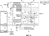
На Фиг.1 показана принципиальная схема системы управления электропитанием СИД лампы, соответствующей настоящему изобретению. В этом примере СИД лампа представляет собой лампу с двухканальной схемой и двумя СИД схемами, то есть СИД лампа имеет два СИД канала с двумя шунтированными СИД схемами на СИД канал.Figure 1 shows a schematic diagram of a power management system of an LED lamp according to the present invention. In this example, the LED lamp is a lamp with a two-channel circuit and two LED circuits, that is, the LED lamp has two LED channels with two LED shunt circuits per LED channel.
СИД лампа 30 с использованием системы управления электропитанием включает контроллер 58 СИД, имеющий микроконтроллер 40, в рабочем положении соединенный со специализированной интегральной схемой 50 гистерезисного управления, управляющей мощностью, подаваемой в два СИД канала 60. Каждый СИД канал 60 имеет переключатель 62 каналов и СИД схему 64, соединенные последовательно между напряжением и общим проводником. Каждый переключатель 62 каналов принимает управляющий сигнал 63 переключения каналов от специализированной интегральной схемы 50 гистерезисного управления для управления током в СИД канале 60. В этом примере каждая СИД схема 64 включает диод 67, расположенный параллельно катушке 66 индуктивности, расположенной последовательно с двумя шунтированными СИД схемами 83 и сопротивлением 81. Каждая шунтированная СИД схема 83 включает шунтовой переключатель 68, расположенный параллельно СИД источнику 80. СИД источник 80 включает один или более светодиодов, соединенных последовательно и/или параллельно друг другу, для генерирования света необходимого цвета или длины волны. Каждый шунтовой переключатель 68 принимает сигнал 69 управления шунтированием от специализированной интегральной схемы 50 гистерезисного управления. Шунтовой переключатель 68 замыкает накоротко ток канала вблизи связанного с ним СИД источника для управления световым выходом связанного с ним СИД источника. В этом примере основная электронная топология представляет собой гистерезисный вольтодобавочный преобразователь. Контроллер 58 СИД включает запоминающее устройство для данных для хранения оперативной информации, например измеренного оптического потока для СИД источников 80 света, начальных установочных параметров, измеренных рабочих параметров, предельных рабочих параметров и т.п. Специалистам в данной области техники будет понятно, что контроллер 58 СИД может быть одной интегральной схемой или несколькими в рабочем положении соединенными интегральными схемами, обеспечивающими выполнение необходимых функций. Например, контроллер 58 СИД может быть единственной интегральной схемой, включающей микропроцессор со встроенной памятью, или может быть двумя интегральными схемами, одна из которых включает микропроцессор, а другая включает запоминающее устройство.The
Цветовой выход каждого СИД источника 80 может быть подобран для получения светового выхода от СИД лампы 30, необходимого для конкретной цели. В одном варианте осуществления изобретения СИД источники являются "красно-зелено-сине-янтарными". В другом варианте осуществления изобретения СИД источники являются "красно-зелено-сине-белыми". В одном варианте осуществления изобретения СИД источники 80, генерирующие зеленый и синий свет, могут быть в одном СИД канале 60, и СИД источники 80, генерирующие янтарный и красный свет, могут быть в другом СИД канале 60.The color output of each LED of the
Микроконтроллер 40 принимает команды 42, вводимые пользователем, такие как командные сигналы цветности, командные сигналы тусклого света и т.п. Микроконтроллер 40 может также принимать сигналы 44 обратной связи для микроконтроллера, такие как сигналы температурного датчика, сигналы светочувствительного датчика и т.п., как необходимо для конкретного варианта применения. В одном варианте осуществления изобретения сигналы 44 обратной связи генерируются специализированной интегральной схемой 50 гистерезисного управления на основе сигналов 52 управления обратной связи, таких как сигналы температурного датчика, сигналы светочувствительного датчика и т.п., как необходимо для конкретного варианта применения. Микроконтроллер 40 генерирует разрешающий сигнал 46 стороны высокого напряжения и широтномодулированный сигнал 48 стороны низкого напряжения, которые поступают в специализированную интегральную схему 50 гистерезисного управления в ответ на команды, вводимые пользователем 42, и, возможно, сигналы 44 обратной связи для микроконтроллера.The
Специализированная интегральная схема 50 гистерезисного управления также принимает сигналы 54 обратной связи по току, которые указывают на ток в каждом из СИД каналов 60, и, реагируя на сигналы 54 обратной связи по току, регулирует сигналы 63 управления переключателем каналов. Специализированная интегральная схема 50 гистерезисного управления генерирует сигналы 63 управления переключателем каналов и сигналы 69 управления шунтовым переключателем в ответ на разрешающие сигналы 46 стороны высокого напряжения, широтномодулированные сигналы 48 стороны низкого напряжения, сигналы 54 обратной связи по току и, возможно, сигналы 52 управления обратной связи.The dedicated hysteresis control integrated
В ходе работы пользователь выдает команды 42, вводимые пользователем, микроконтроллеру 40, который генерирует разрешающие сигналы 46 стороны высокого напряжения и широтномодулированные сигналы 48 стороны низкого напряжения. Специализированная интегральная схема 50 гистерезисного управления принимает разрешающие сигналы 46 стороны высокого напряжения и широтномодулированные сигналы 48 стороны низкого напряжения и генерирует сигналы 63 управления переключателем каналов и сигналы 69 управления шунтовым переключателем. Контроллер 58 СИД может осуществлять способ управления электропитанием светодиодов, как описано в связи с Фиг.2 ниже, при генерировании сигналов 63 управления переключателем каналов и сигналов 69 управления шунтовым переключателем. Как показано на Фиг.1, сигнал 63 управления переключателем каналов выдается каждому из переключателей 62 каналов для управления током в СИД канале 60, и сигнал 69 управления шунтовым переключателем выдается каждому из шунтовых переключателей 68 для управления световым выходом связанного с ним СИД источника. В одном варианте осуществления изобретения специализированная интегральная схема 50 гистерезисного управления принимает и реагирует на сигналы 54 обратной связи по току от СИД каналов 60. В другом варианте осуществления изобретения специализированная интегральная схема 50 гистерезисного управления принимает и реагирует на сигналы 52 управления обратной связи от температурного и/или одного или более светочувствительных датчиков (не показаны). Специалистам в данной области техники будет понятно, что контроллер 58 СИД может принимать управляющие сигналы системы, как необходимо для конкретного варианта применения системы освещения. Управляющие сигналы системы могут генерироваться проводными схемами управления и/или в соответствии с ними, например, такими как протокол DALI, протокол DMX и т.п., или в соответствии с беспроводными схемами управления, такими как протокол Zigbee и т.п. В одном варианте осуществления изобретения контроллер 58 СИД может передавать управляющие сигналы системы другим лампам в системе освещения для того, чтобы лампы произвели такие же изменения, как исходная лампа. Например, контроллер 58 СИД может передавать управляющий сигнал системы, выдающий команду другим лампам в помещении изменить цветовой выход света для согласования изменений цвета с исходной лампой, как может требоваться для снижения потери мощности в исходной лампе.In the course of operation, the user issues commands 42 input by the user to the
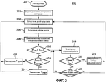
На Фиг.2 показана блок-схема последовательности операций способа управления электропитанием СИД лампы, соответствующего настоящему изобретению. СИД лампа имеет несколько СИД каналов, каждый из которых имеет переключатель каналов, расположенный последовательно с несколькими СИД схемами. Каждая из СИД схем имеет шунтовой переключатель, расположенный параллельно СИД источнику света. В одном варианте осуществления изобретения СИД лампа представляет собой лампу с двухканальной схемой и двумя СИД схемами, как показано на Фиг.1. В другом варианте осуществления изобретения СИД лампа представляет собой лампу с четырехканальной схемой и одной СИД схемой, как показано на Фиг.3.Figure 2 shows a flowchart of a method for power management of an LED lamp according to the present invention. The LED lamp has several LED channels, each of which has a channel selector located in series with several LED circuits. Each of the LED circuits has a shunt switch located parallel to the LED light source. In one embodiment of the invention, the LED lamp is a lamp with a two-channel circuit and two LED circuits, as shown in FIG. In another embodiment, the LED lamp is a lamp with a four-channel circuit and one LED circuit, as shown in FIG. 3.
Как показано на Фиг.2, осуществление способа 200 начинается в пункте 201 и включает задание 202 установочных параметров СИД лампы для СИД лампы, вычисление 204 долей силы света для каждого из СИД источников света на основе установочных параметров СИД лампы, вычисление 206 рабочих циклов для шунтовых переключателей на основе долей силы света и вычисление 208 потери (Ploss) мощности в электронных схемах СИД лампы для СИД лампы на основе рабочих циклов. Потеря (Ploss) мощности в электронных схемах СИД лампы составляет потерю мощности в электронных схемах СИД лампы и не включает потерю мощности в СИД источниках.As shown in FIG. 2, the implementation of
Способ 200 продолжается определением 210 того, является ли потеря (Ploss) мощности в электронных схемах СИД лампы меньшей, чем предел (Plim) потери мощности в электронных схемах СИД лампы. Когда потеря (Ploss) мощности в электронных схемах СИД лампы не является меньшей, чем предел (Plim) потери мощности в электронных схемах СИД лампы, определяется, является ли мощность (Pmain) переключателя каналов меньшей, чем мощность (Pbypass) шунтового переключателя. Когда мощность (Pmain) переключателя каналов не является меньшей, чем мощность (Pbypass) шунтового переключателя, мощность (Pmain) переключателя каналов снижают 214, и способ 200 может продолжаться вычислением 204 обновленных долей силы света. Когда мощность (Pmain) переключателя каналов является меньшей, чем мощность (Pbypass) шунтового переключателя, мощность (Pbypass) шунтового переключателя снижают 216, и способ 200 может продолжаться вычислением 204 обновленных долей силы света.The
Когда потеря (Ploss) мощности в электронных схемах СИД лампы является меньшей, чем предел (Plim) потери мощности в электронных схемах СИД лампы, нормальная работа может продолжаться 218. В одном варианте осуществления изобретения температура СИД лампы может контролироваться для определения, является ли измеренная температура (Tmeas) меньшей, чем температурный предел (Tlim) 220. Когда измеренная температура (Tmeas) не является меньшей, чем температурный предел (Tlim), команда снижения яркости света может регулироваться для уменьшения светового выхода СИД лампы 221, и способ 200 может продолжаться вычислением обновленных долей силы света для притушенной СИД лампы 204. Специалистам в данной области техники будет понятно, что измеренную температуру (Tmeas) можно также понижать посредством изменения индекса цветопередачи и/или цветовой температуры, как необходимо для конкретного варианта применения. Когда измеренная температура (Tmeas) является меньшей, чем температурный предел (Tlim), нормальная работа может продолжаться 218. В одном варианте осуществления изобретения способ 200 может продолжаться контролем 222 изменений вводимых пользователем команд. Когда есть изменения вводимых пользователем команд, способ 200 может продолжаться вычислением 204 обновленных долей силы света для новых вводимых пользователем команд. Когда изменений вводимых пользователем команд нет, нормальная работа может продолжаться 218. Специалистам в данной области техники будет понятно, что контроль 220 температуры и/или контроль 222 вводимых пользователем команд может быть исключен, как необходимо для конкретного варианта применения. Дополнительные рабочие параметры, такие как цвета индивидуального светодиода, цвет света СИД лампы, качество света СИД лампы и т.п., могут контролироваться как необходимо.When the power loss (P loss ) in the LED lamp electronic circuits is less than the limit (P lim ) of the power loss in the LED lamp electronic circuits, normal operation can continue 218. In one embodiment of the invention, the temperature of the LED lamp can be monitored to determine if the measured temperature (T meas ) is lower than the temperature limit (T lim ) 220. When the measured temperature (T meas ) is not lower than the temperature limit (T lim ), the light dimmer command can be adjusted to reduce the light output The LEDs of the
Задание 202 установочных параметров СИД лампы для СИД лампы может включать задание установочных параметров СИД лампы, таких как задание цвета, задание приглушенности света и т.п. Начальные величины могут быть заданы изготовителем, проектировщиком освещения или могут быть сохраненными пользовательскими установками от предыдущего использования.The setting 202 of the LED lamp settings for the LED lamp may include setting the lamp LED settings, such as a color setting, a dim setting, or the like. Initial values can be set by the manufacturer, lighting designer or can be saved by user settings from previous use.
Вычисление 208 потерь (Ploss) мощности в электронных схемах СИД лампы для СИД лампы на основе рабочих циклов может включать вычисление индивидуальных потерь мощности для переключателей каналов, шунтовых переключателей и т.п. и суммирование индивидуальных потерь мощности для вычисления суммарной потери (Ploss) мощности в электронных схемах СИД лампы для СИД лампы.The calculation of 208 power loss (P loss ) in LED lamp electronic circuits for LED lamps based on duty cycles may include the calculation of individual power losses for channel switches, shunt switches, and the like. and summing the individual power losses to calculate the total power loss (P loss ) in the electronic circuitry of the LED lamp for the LED lamp.
Уменьшение 214 мощности (Pmain) переключателя каналов может включать действия по уменьшению тока СИД канала в одном или более СИД каналов для снижения яркости СИД лампы и/или расширения гистерезисного окна одного или более СИД каналов для уменьшения частоты переключений переключателей каналов. Расширение гистерезисного окна сохраняет прежний средний ток через СИД источники при более низкой частоте. Однако это может вызвать незначительный цветовой сдвиг, так как форма волны при пониженной частоте может отличаться от формы волны, использованной при калибровке СИД лампы. Специалистам в данной области техники будет понятно, что величина уменьшения мощности (Pmain) переключателя каналов может быть выбрана как необходимо для конкретного варианта применения.Reducing the channel switch power (P main ) 214 may include actions to reduce the channel LED current in one or more channel LEDs to reduce the lamp LED brightness and / or to expand the hysteresis window of one or more channel LEDs to reduce channel switching frequency. The expansion of the hysteresis window maintains the same average current through LED sources at a lower frequency. However, this may cause a slight color shift, since the waveform at a lower frequency may differ from the waveform used in the calibration of the LED lamps. Those skilled in the art will appreciate that the amount of power reduction (P main ) of the channel selector can be selected as needed for a particular application.
Действия, предпринимаемые для уменьшения мощности (Pmain) переключателя каналов, могут быть предприняты в разном порядке и разной степени. Затемнение посредством уменьшения тока СИД канала и расширения гистерезисного окна может использоваться отдельно или в комбинации, как необходимо для конкретного варианта применения. В одном варианте осуществления изобретения проектировщик освещения может задать предпочтительный порядок действий, то есть, что будет выполнено первым: уменьшение тока СИД канала в одном или более СИД каналов или расширение гистерезисного окна. В другом варианте осуществления изобретения предпочтительный порядок действий задан изготовителем. В другом варианте осуществления изобретения первое действие может продолжаться, пока не будет достигнут первый предел, затем может быть выполнено второе действие, пока не будет достигнут второй предел, и тогда первое действие может быть выполнено снова. Например, ток СИД канала можно уменьшать, пока световой выход не будет ниже первого предела, затем гистерезисное окно можно расширять, пока цвет не достигнет второго предела, и затем ток СИД канала может быть дополнительно уменьшен. Специалистам в данной области техники будет понятно, что различные подходы могут не быть пригодными для конкретного варианта применения. Например, снижение яркости СИД лампы может быть нежелательным, когда требуется минимальный световой поток, и СИД лампа уже работает на минимальном уровне. В другом примере расширение гистерезисного окна может быть нежелательным, когда требуется постоянный цвет света.The actions taken to reduce the power (P main ) of the channel selector can be taken in a different order and to different degrees. Dimming by reducing the LED channel current and expanding the hysteresis window can be used alone or in combination, as needed for a particular application. In one embodiment of the invention, the lighting designer may specify a preferred course of action, that is, what will be done first: reducing the current of the LED channel in one or more LED channels or expanding the hysteresis window. In another embodiment, the preferred course of action is specified by the manufacturer. In another embodiment, the first action may continue until the first limit is reached, then a second action can be performed until the second limit is reached, and then the first action can be performed again. For example, the LED channel current can be reduced until the light output is below the first limit, then the hysteresis window can be expanded until the color reaches the second limit, and then the LED channel current can be further reduced. Those skilled in the art will understand that various approaches may not be suitable for a particular application. For example, reducing the brightness of an LED lamp may be undesirable when a minimum luminous flux is required, and the LED lamp is already operating at a minimum level. In another example, expansion of the hysteresis window may be undesirable when a constant color of light is required.
Уменьшение 216 мощности (Pbypass) шунтового переключателя может включать уменьшение тока СИД канала в одном или более СИД каналов для уменьшения яркости СИД лампы, изменения цвета света для выравнивания рабочих циклов СИД источников света в одном или более СИД каналов и/или изменения индекса цветопередачи для выравнивания рабочих циклов СИД источников света в одном или более СИД каналов. Изменение цвета света для выравнивания рабочих циклов СИД источников света в каждом СИД канале позволяет уменьшать ток в СИД каналах для максимизации рабочих циклов СИД источников света в каждом канале. Изменение индекса цветопередачи для выравнивания рабочих циклов СИД источников света в каждом СИД канале позволяет уменьшать ток в СИД каналах для максимизации рабочих циклов СИД источников света в каждом СИД канале при сохранении точки и интенсивности цвета для СИД лампы. Специалистам в данной области техники будет понятно, что величина уменьшения мощности (Pbypass) шунтового переключателя может быть выбрана как необходимо для конкретного варианта применения.Reducing the shunt switch power (P bypass ) 216 may include decreasing the channel LED current in one or more LED channels to reduce the brightness of the LED lamps, changing the color of the light to even out the light cycles of the LED light sources in one or more LED channels, and / or changing the color rendering index for alignment of duty cycles of LED light sources in one or more LED channels. Changing the color of the light to align the operating cycles of the LED light sources in each LED channel allows you to reduce the current in the LED channels to maximize the operating cycles of the LED light sources in each channel. Changing the color rendering index to align the operating cycles of the LED light sources in each LED channel allows to reduce the current in the LED channels to maximize the operating cycles of the LED light sources in each LED channel while maintaining the point and color intensity for the LED lamps. Those skilled in the art will understand that the amount of power reduction (P bypass ) of the shunt switch can be selected as needed for a particular application.
Действия, предпринимаемые для уменьшения мощности (Pbypass) шунтового переключателя, могут быть предприняты в различном порядке и разной степени. Затемнение посредством уменьшения тока СИД канала, уменьшение частоты переключений, изменение цвета света и/или изменение индекса цветопередачи могут использоваться отдельно или в комбинации, как необходимо для конкретного варианта применения. В одном варианте осуществления изобретения проектировщик освещения может задавать предпочтительный порядок действий, то есть выполнение первым уменьшения тока СИД канала, уменьшения частоты переключений, изменения цвета света или изменения индекса цветопередачи. В другом варианте осуществления изобретения предпочтительный порядок действий задан изготовителем. В другом варианте осуществления изобретения может выполняться первое действие, пока не будет достигнут первый предел, затем может выполняться второе действие, пока не будет достигнут второй предел, и затем первое действие может быть выполнено снова. Например, ток СИД канала можно уменьшать, пока световой выход не будет ниже первого предела, затем можно изменять цвет света, пока цвет не достигнет второго предела, и затем может быть дополнительно уменьшен ток СИД канала. Различные действия могут быть выполнены в любом порядке и в любой необходимой степени. Специалистам в данной области техники будет понятно, что различные подходы могут не быть пригодными для конкретного варианта применения. Например, уменьшение яркости СИД лампы может быть нежелательным, когда требуется минимальный световой поток, а СИД лампа уже работает на минимальном уровне. В другом примере изменение цвета света может быть нежелательным, когда требуется постоянный цвет света. В другом примере изменение индекса цветопередачи может быть нежелательным, когда требуется определенное отображение цвета.The actions taken to reduce the power (P bypass ) of the shunt switch can be taken in a different order and to different degrees. Dimming by reducing the LED current of the channel, reducing the switching frequency, changing the color of the light and / or changing the color rendering index can be used individually or in combination, as necessary for a particular application. In one embodiment of the invention, the lighting designer may specify a preferred course of action, that is, performing the first to reduce the LED channel current, reduce the switching frequency, change the color of the light, or change the color rendering index. In another embodiment, the preferred course of action is specified by the manufacturer. In another embodiment of the invention, a first action may be performed until a first limit is reached, then a second action may be performed until a second limit is reached, and then the first action may be performed again. For example, the LED channel current can be reduced until the light output is below the first limit, then the color of the light can be changed until the color reaches the second limit, and then the LED channel current can be further reduced. Various actions can be performed in any order and to any degree necessary. Those skilled in the art will understand that various approaches may not be suitable for a particular application. For example, reducing the brightness of an LED lamp may be undesirable when a minimum luminous flux is required and the LED lamp is already operating at a minimum level. In another example, a change in the color of light may be undesirable when a constant color of light is required. In another example, changing the color rendering index may be undesirable when a specific color display is required.
В ходе нормальной работы 218, когда потеря (Ploss) мощности в электронных схемах СИД лампы является меньшей, чем предел (Plim) потери мощности в электронных схемах СИД лампы, могут контролироваться входные команды пользователя и рабочие параметры СИД лампы. Контроль 220 измеренной температуры (Tmeas) СИД лампы для определения того, что измеренная температура (Tmeas) является меньшей, чем температурный предел (Tlim), может включать контроль измеренной температуры (Tmeas) СИД лампы при помощи температурного датчика, такого как термистор, терморезистор с отрицательным температурным коэффициентом сопротивления, термопара и т.п., имеющего тепловой контакт с СИД лампой. Измеренная температура (Tmeas) может составлять потерю мощности в электронных схемах СИД лампы и/или потерю мощности в СИД источниках в зависимости от местоположения температурного датчика и теплового контакта. В другом варианте осуществления изобретения контроль измеренной температуры (Tmeas) СИД лампы может включать оценку измеренной температуры (Tmeas) на основе операционных параметров микроконтроллером. Регулирование команды 221 уменьшения яркости, когда измеренная температура (Tmeas) не является меньшей, чем температурный предел (Plim), может включать регулирование команды уменьшения яркости пропорционально величине, на которую измеренная температура (Tmeas) превышает температурный предел (Tlim), заданный для регулятора силы света СИД лампы. Контроль 222 изменений вводимых пользователем команд может включать контроль таких изменений вводимых пользователем команд, как изменения команд цветности, команд уменьшения силы цвета и т.п. для новых установочных параметров СИД лампы. Доли силы света могут быть вычислены 204 для установочных параметров сниженной яркости СИД лампы для получения более низкой температуры и/или для новых входных команд пользователя для новых установочных параметров СИД лампы.During
Специалистам в данной области техники будет понятно, что рабочие параметры СИД лампы также могут контролироваться, когда потеря (Ploss) мощности в электронных схемах СИД лампы больше или равна пределу (Plim) потери мощности в электронных схемах СИД лампы, как необходимо для конкретного варианта применения. Например, корректирующие меры 214 для уменьшения мощности (Pmain) переключателя каналов или уменьшения 216 мощности (Pbypass) шунтового переключателя могут быть недостаточными для обеспечения того, что потеря (Ploss) мощности в электронных схемах СИД лампы является меньшей, чем предел (Plim) потери мощности в электронных схемах СИД лампы. Измеренная температура (Tmeas) СИД лампы может контролироваться, и команда тусклого света регулируется, когда измеренная температура (Tmeas) не является меньшей, чем температурный предел (Tlim), и когда корректирующие меры недостаточны для уменьшения потери (Ploss) мощности в электронных схемах СИД лампы ниже предела (Plim) потери мощности в электронных схемах СИД лампы. В одном варианте осуществления изобретения могут контролироваться рабочие параметры СИД лампы, когда микроконтроллер определяет, что корректирующие меры недостаточны. В другом варианте осуществления изобретения могут контролироваться рабочие параметры СИД лампы, когда корректирующие меры для уменьшения 214 мощности (Pmain) переключателя каналов и/или уменьшения 216 мощности (Pbypass) шунтового переключателя были выполнены заданное количество раз без уменьшения потерь (Ploss) мощности в электронных схемах СИД лампы ниже предела (Plim) потери мощности в электронных схемах СИД лампы.Those skilled in the art will understand that the operating parameters of an LED lamp can also be controlled when the loss (P loss ) of power in the electronic circuits of the LED lamp is greater than or equal to the limit (P lim ) of the power loss in the electronic circuits of the LED lamp, as necessary for a particular embodiment application. For example,
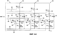
На Фиг.3, на которой подобные элементы имеют такие же ссылочные позиции, как и на Фиг.1, показана принципиальная схема другого варианта осуществления системы управления электропитанием СИД лампы, соответствующей настоящему изобретению. В этом примере СИД лампа представляет собой лампу с четырехканальной схемой и одной СИД схемой, то есть СИД лампа имеет четыре СИД канала с одной шунтированной СИД схемой на СИД канал. Во всех СИД каналах могут быть расположены СИД источники разных цветов таким образом, что током можно осуществлять управление для каждого из цветов светодиодов. Потери мощности на шунтовые переключения могут быть минимизированы, поскольку ток СИД канала может быть выключен переключателем каналов для СИД канала, когда определенный цвет не требуется.Figure 3, in which similar elements have the same reference position as in Figure 1, shows a schematic diagram of another embodiment of a LED lamp power management system according to the present invention. In this example, the LED lamp is a lamp with a four-channel circuit and one LED circuit, that is, the LED lamp has four channel LEDs with one shunted LED circuit per LED channel. In all LED channels, LED sources of different colors can be located so that current can be controlled for each of the colors of the LEDs. Power losses due to shunt switching can be minimized since the current of the LED channel can be turned off by the channel selector for the LED channel when a specific color is not required.
СИД лампа 30 с использованием системы управления электропитанием включает контроллер 58 СИД, имеющий микроконтроллер 40, в рабочем положении соединенный со специализированной интегральной схемой 50 гистерезисного управления, управляющей электропитанием четырех СИД каналов 60. Каждый СИД канал 60 имеет переключатель 62 каналов и СИД схему 64, соединенные последовательно между напряжением и общим проводником. Каждый переключатель 62 каналов принимает сигнал 63 управления переключателем каналов от специализированной интегральной схемы 50 гистерезисного управления для управления током СИД канала 60. В этом примере каждая СИД схема 64 включает диод 67, расположенный параллельно катушке 66 индуктивности, расположенной последовательно с шунтовым переключателем 68. Каждый шунтовой переключатель 68 принимает сигнал 69 управления шунтовым переключателем от специализированной интегральной схемы 50 гистерезисного управления и соединен параллельно СИД источнику 80. Шунтовой переключатель 68 замыкает накоротко ток канала вокруг связанного с ним СИД источника для управления световым выходом связанного с ним СИД источника. В этом примере основная электронная топология представляет собой гистерезисный вольтодобавочный преобразователь. Катушка 66 индуктивности для каждого СИД канала 60 может иметь размер для обеспечения желательной частоты переключений для конкретного светодиода 60 в этом СИД канале 60. В одном варианте осуществления изобретения СИД источники 80 в каждом из СИД каналов 60 могут генерировать свет различных цветов.The
В ходе работы пользователь выдает входные команды 42 пользователя микроконтроллеру 40, который генерирует разрешающие сигналы 46 стороны высокого напряжения и широтномодулированные сигналы 48 стороны низкого напряжения. Специализированная интегральная схема 50 гистерезисного управления принимает разрешающие сигналы 46 стороны высокого напряжения и широтномодулированные сигналы 48 стороны низкого напряжения и генерирует сигналы 63 управления переключателем каналов и сигналы 69 управления шунтовым переключателем. Контроллер 58 СИД может осуществлять способ управления электропитанием светодиодов, как описано в связи с Фиг.2 выше, для генерирования сигналов 63 управления переключателем каналов и сигналов 69 управления шунтовым переключателем. Как показано на Фиг.3, сигнал 63 управления переключателем каналов поступает к каждому из переключателей 62 каналов для управления током в СИД канале 60, и сигнал 69 управления шунтовым переключателем поступает к каждому из шунтовых переключателей 68 для управления световым выходом связанного с ним светодиода.In the course of operation, the user issues user input commands 42 to the
В одном варианте осуществления изобретения катушка 66 индуктивности для каждого СИД канала 60 включает две или больше катушек индуктивности, причем одна из катушек индуктивности имеет размер для насыщения при сильном токе. Ток является сильным в ходе нормальной работы при проектном рабочем режиме, генерируя белый свет с оптимальным цветом и индексом цветопередачи, таким образом, что одна катушка индуктивности в каждом СИД канале 60 нормально насыщается. Когда ток в СИД канале 60 слабый, например, при работе с цветом и/или индексом цветопередачи, отличающимися от проектного рабочего режима, одна насыщенная катушка индуктивности в каждом СИД канале 60 становится ненасыщенной. Это увеличивает полную индуктивность катушки 66 индуктивности и снижает частоты переключений для СИД канала 60. Две или больше катушек 66 индуктивности для каждого СИД канала 60 могут быть отобраны таким образом, что гистерезисное окно может быть выбрано для постоянного процентного отношения уровня тока СИД канала 60 при сохранении частоты переключений в приемлемом диапазоне. Например, если ток снижен с коэффициентом 10, и все же желательно поддерживать гистерезисное окно на уровне 10% среднего тока, частота переключений должна быть повышена с коэффициентом 10, если не используются насыщаемые катушки индуктивности. Однако благодаря использованию насыщаемой катушки индуктивности с девятикратной величиной относительно ненасыщенной катушки индуктивности, полная индуктивность будет увеличиваться до 10-кратной относительно первоначальной величины при низких уровнях тока (когда катушка индуктивности становится ненасыщенной). Это допускает неизменность частоты переключений, как необходимо.In one embodiment of the invention, the
Хотя описанные здесь варианты осуществления изобретения рассматриваются как предпочтительные в настоящее время, в них могут быть внесены различные изменения и модификации без отхода от объема изобретения. Объем изобретения обозначен в прилагаемой формуле изобретения, и все изменения, которые входят в пределы значения и рамок эквивалентов, предполагаются охваченными ей.Although the embodiments described herein are considered to be preferred at the present time, various changes and modifications may be made to them without departing from the scope of the invention. The scope of the invention is indicated in the attached claims, and all changes that fall within the meaning and scope of equivalents are intended to be encompassed by it.
Claims (21)
контроллер (58) СИД;
множество СИД каналов (60), в рабочем положении соединенных с контроллером (58) СИД, причем каждый из множества СИД каналов (60) имеет переключатель (62) каналов, расположенный последовательно, по меньшей мере, с одной шунтированной СИД схемой (83), причем шунтированная СИД схема (83) имеет шунтовой переключатель (68), расположенный параллельно СИД источнику (80);
в которой контроллер (58) СИД снижает потерю мощности в одном из переключателя (62) каналов и шунтового переключателя (68), когда потеря (Ploss) мощности в электронных схемах СИД лампы превышает предел (Рlim) потери мощности в электронных схемах СИД лампы.1. LED lamp containing:
LED controller (58);
a plurality of LED channels (60) connected in operation to the LED controller (58), each of the plurality of LED channels (60) having a channel selector (62) arranged in series with at least one LED shunt circuit (83), moreover, the shunted LED circuit (83) has a shunt switch (68) located parallel to the LED source (80);
in which the LED controller (58) reduces the power loss in one of the channel switch (62) and the shunt switch (68) when the power loss (P loss ) in the electronic circuit of the LED lamp exceeds the limit (P lim ) of the power loss in the electronic circuit of the LED lamp .
получение СИД лампы, имеющей множество СИД каналов, причем каждый из множества СИД каналов имеет переключатель каналов, расположенный последовательно, по меньшей мере, с одной шунтированной СИД схемой, причем шунтированная СИД схема имеет шунтовой переключатель, расположенный параллельно СИД источнику;
задание установочных параметров СИД лампы для СИД лампы (202);
вычисление долей силы света для каждого из СИД источников света на основе установочных параметров (204) СИД лампы;
вычисление рабочих циклов для шунтовых переключателей на основе долей (206) силы света;
вычисление потерь (Ploss) мощности в электронных схемах СИД лампы для СИД лампы на основе рабочих циклов (208);
определение того, является ли потеря (Ploss) мощности в электронных схемах СИД лампы меньшей, чем предел (Plim) потери мощности в электронных схемах СИД лампы (210);
определение того, является ли мощность (Pmain) переключателя каналов для переключателей каналов меньшей, чем мощность (Pbypass) шунтового переключателя для шунтовых переключателей, когда потеря (Ploss) мощности в электронных схемах СИД лампы не является меньшей, чем предел (Рlim) потери мощности в электронных схемах СИД лампы;
уменьшение (214) мощности (Pmain) переключателя каналов, когда мощность (Pmain) переключателя каналов не является меньшей, чем мощность (Pbypass) шунтового переключателя; и
уменьшение (216) мощности (Pbypass) шунтового переключателя, когда мощность (Pmain) переключателя каналов является меньшей, чем мощность (Pbypass) шунтового переключателя.11. A method of power management of an LED lamp, comprising:
receiving an LED lamp having a plurality of LED channels, each of the plurality of LED channels having a channel selector arranged in series with at least one LED shunt circuit, the LED shunt circuit having a shunt switch parallel to the LED source;
setting the LED lamp settings for the LED lamp (202);
calculating the luminous fractions for each of the LED light sources based on the settings (204) of the LED lamp;
calculation of duty cycles for shunt switches based on luminous intensity fractions (206);
calculation of power loss (P loss ) in LED lamp electronic circuits for LED lamps based on duty cycles (208);
determining whether the power loss (P loss ) in the LED lamp electronic circuits is less than the limit (P lim ) of the power loss in the LED lamp electronic circuits (210);
determination of whether the power (P main ) of the channel switch for channel switches is less than the power (P bypass ) of the shunt switch for shunt switches when the loss (P loss ) of power in the electronic circuitry of the LED lamp is not less than the limit (P lim ) power loss in the electronic circuits of the LED lamp;
a decrease (214) in the power (P main ) of the channel selector when the power (P main ) of the channel selector is not less than the power (P bypass ) of the shunt switch; and
reducing (216) the power (P bypass ) of the shunt switch when the power (P main ) of the channel switch is less than the power (P bypass ) of the shunt switch.
определение (220), является ли измеренная температура (Tmeas) СИД лампы меньшей, чем температурный предел (Tlim); и
регулирование команды уменьшения яркости для СИД лампы, когда измеренная температура (Tmeas) не является меньшей, чем температурный предел (Тlim) (220).18. The method according to claim 11, also containing:
determining (220) whether the measured temperature (T meas ) of the LED lamp is less than the temperature limit (T lim ); and
adjusting the brightness reduction command for the LED lamp when the measured temperature (T meas ) is not lower than the temperature limit (T lim ) (220).
СИД лампу, имеющую множество СИД каналов, причем каждый из множества СИД каналов имеет переключатель каналов, расположенный последовательно, по меньшей мере, с одной шунтированной СИД схемой, причем шунтированная СИД схема имеет шунтовой переключатель, соединенный параллельно СИД источнику света;
средства для задания установочных параметров для СИД лампы;
средства для вычисления долей силы света для каждого из СИД источников света на основе установочных параметров для СИД лампы;
средства для вычисления рабочих циклов для шунтовых переключателей на основе долей силы света;
средства для вычисления потери (Ploss) мощности в электронных схемах СИД лампы для СИД лампы на основе рабочих циклов;
средства для определения того, является ли потеря (Ploss) мощности в электронных схемах СИД лампы меньшей, чем предел (Plim) потери мощности в электронных схемах СИД лампы;
средства для определения того, является ли мощность (Pmain) переключателя каналов для переключателей каналов меньше, чем мощность (Pbypass) шунтового переключателя для шунтовых переключателей, когда потеря (Ploss) мощности в электронных схемах СИД лампы не является меньшей, чем предел (Plim) потери мощности в электронных схемах СИД лампы;
средства для уменьшения мощности (Pmain) переключателя каналов, когда мощность (Pmain) переключателя каналов не является меньшей, чем мощность (Pbypass) шунтового переключателя; и
средства для уменьшения мощности (Pbypass) шунтового переключателя, когда мощность (Pmain) переключателя каналов является меньшей, чем мощность (Pbypass) шунтового переключателя. 21. The power management system of the LED lamp, containing:
An LED lamp having a plurality of LED channels, each of the plurality of LED channels having a channel selector arranged in series with at least one LED shunt circuit, the LED shunt circuit having a shunt switch connected in parallel with the LED light source;
means for setting parameters for the LED lamp;
means for calculating the luminous intensity fractions for each of the LED light sources based on the settings for the LED lamp;
means for calculating duty cycles for shunt switches based on luminous intensity fractions;
means for calculating the power loss (P loss ) in the electronic circuits of the LED lamp for LED lamps based on duty cycles;
means for determining whether the power loss (P loss ) in the LED lamp electronic circuits is less than the limit (P lim ) of the power loss in the LED lamp electronic circuits;
means for determining whether the power (P main ) of the channel switch for channel switches is less than the power (P bypass ) of the shunt switch for shunt switches when the loss (P loss ) of power in the electronic circuits of the LED lamp is not less than the limit ( P lim ) power loss in the electronic circuits of the LED lamp;
means for reducing the power (P main ) of the channel selector when the power (P main ) of the channel selector is not less than the power (P bypass ) of the shunt switch; and
means for reducing the power (P bypass ) of the shunt switch when the power (P main ) of the channel selector is less than the power (P bypass ) of the shunt switch.
Applications Claiming Priority (3)
| Application Number | Priority Date | Filing Date | Title |
|---|---|---|---|
| US1212707P | 2007-12-07 | 2007-12-07 | |
| US61/012,127 | 2007-12-07 | ||
| PCT/IB2008/055036 WO2009072058A2 (en) | 2007-12-07 | 2008-12-02 | Led lamp power management system and method |
Publications (2)
| Publication Number | Publication Date |
|---|---|
| RU2010128104A RU2010128104A (en) | 2012-01-20 |
| RU2481752C2 true RU2481752C2 (en) | 2013-05-10 |
Family
ID=40627111
Family Applications (1)
| Application Number | Title | Priority Date | Filing Date |
|---|---|---|---|
| RU2010128104/07A RU2481752C2 (en) | 2007-12-07 | 2008-12-02 | System and method to control led lamp power supply |
Country Status (8)
| Country | Link |
|---|---|
| US (1) | US8400071B2 (en) |
| EP (1) | EP2220914A2 (en) |
| JP (1) | JP5335808B2 (en) |
| KR (1) | KR20100096231A (en) |
| CN (1) | CN101889477A (en) |
| BR (1) | BRPI0820090A2 (en) |
| RU (1) | RU2481752C2 (en) |
| WO (1) | WO2009072058A2 (en) |
Cited By (1)
| Publication number | Priority date | Publication date | Assignee | Title |
|---|---|---|---|---|
| RU2614037C1 (en) * | 2014-09-29 | 2017-03-22 | Мицубиси Электрик Корпорейшн | Light source control device and light source control method |
Families Citing this family (59)
| Publication number | Priority date | Publication date | Assignee | Title |
|---|---|---|---|---|
| US20050259424A1 (en) | 2004-05-18 | 2005-11-24 | Zampini Thomas L Ii | Collimating and controlling light produced by light emitting diodes |
| US7766511B2 (en) | 2006-04-24 | 2010-08-03 | Integrated Illumination Systems | LED light fixture |
| US7729941B2 (en) | 2006-11-17 | 2010-06-01 | Integrated Illumination Systems, Inc. | Apparatus and method of using lighting systems to enhance brand recognition |
| US8013538B2 (en) | 2007-01-26 | 2011-09-06 | Integrated Illumination Systems, Inc. | TRI-light |
| US8742686B2 (en) | 2007-09-24 | 2014-06-03 | Integrated Illumination Systems, Inc. | Systems and methods for providing an OEM level networked lighting system |
| US8255487B2 (en) | 2008-05-16 | 2012-08-28 | Integrated Illumination Systems, Inc. | Systems and methods for communicating in a lighting network |
| US8093821B2 (en) * | 2009-02-05 | 2012-01-10 | The Hong Kong Polytechnic University | Driving method for improving luminous efficacy of a light emitting diode |
| US8585245B2 (en) | 2009-04-23 | 2013-11-19 | Integrated Illumination Systems, Inc. | Systems and methods for sealing a lighting fixture |
| TWI538553B (en) * | 2009-08-25 | 2016-06-11 | 皇家飛利浦電子股份有限公司 | Multichannel lighting unit and driver for supplying current to light sources in multichannel lighting unit |
| CA2772759C (en) * | 2009-09-04 | 2017-02-28 | Koninklijke Philips Electronics N.V. | Light emitting diode circuit |
| DE102010008275B4 (en) * | 2010-02-17 | 2019-10-10 | Continental Automotive Gmbh | Device for powering several LED units |
| DE102010003136A1 (en) * | 2010-03-23 | 2011-09-29 | Osram Gesellschaft mit beschränkter Haftung | Circuit arrangement and method for operating at least one LED |
| DE102010003244A1 (en) * | 2010-03-25 | 2011-09-29 | Osram Gesellschaft mit beschränkter Haftung | Method and circuit arrangement for operating a plurality of LEDs |
| WO2011126374A2 (en) * | 2010-04-09 | 2011-10-13 | Eldolab Holding B.V. | Driver system for driving a plurality of led's |
| US20120062120A1 (en) * | 2010-09-14 | 2012-03-15 | Riesebosch Scott A | Thermal foldback circuit with dimmer monitor |
| US10178723B2 (en) | 2011-06-03 | 2019-01-08 | Cree, Inc. | Systems and methods for controlling solid state lighting devices and lighting apparatus incorporating such systems and/or methods |
| US8644699B2 (en) | 2011-02-17 | 2014-02-04 | Nokia Corporation | Method and apparatus for light emitting diode control |
| US9066381B2 (en) | 2011-03-16 | 2015-06-23 | Integrated Illumination Systems, Inc. | System and method for low level dimming |
| US8823289B2 (en) * | 2011-03-24 | 2014-09-02 | Cirrus Logic, Inc. | Color coordination of electronic light sources with dimming and temperature responsiveness |
| US8939604B2 (en) | 2011-03-25 | 2015-01-27 | Arkalumen Inc. | Modular LED strip lighting apparatus |
| US9967940B2 (en) | 2011-05-05 | 2018-05-08 | Integrated Illumination Systems, Inc. | Systems and methods for active thermal management |
| US9060400B2 (en) * | 2011-07-12 | 2015-06-16 | Arkalumen Inc. | Control apparatus incorporating a voltage converter for controlling lighting apparatus |
| US11917740B2 (en) | 2011-07-26 | 2024-02-27 | Hunter Industries, Inc. | Systems and methods for providing power and data to devices |
| US8710770B2 (en) | 2011-07-26 | 2014-04-29 | Hunter Industries, Inc. | Systems and methods for providing power and data to lighting devices |
| US9521725B2 (en) | 2011-07-26 | 2016-12-13 | Hunter Industries, Inc. | Systems and methods for providing power and data to lighting devices |
| US9609720B2 (en) | 2011-07-26 | 2017-03-28 | Hunter Industries, Inc. | Systems and methods for providing power and data to lighting devices |
| US20150237700A1 (en) | 2011-07-26 | 2015-08-20 | Hunter Industries, Inc. | Systems and methods to control color and brightness of lighting devices |
| US10874003B2 (en) | 2011-07-26 | 2020-12-22 | Hunter Industries, Inc. | Systems and methods for providing power and data to devices |
| DK2742775T3 (en) | 2011-08-08 | 2019-02-18 | Philips Lighting Holding Bv | LED LIGHT SOURCE WITH REDUCED FLASHER |
| US8581519B2 (en) * | 2011-08-25 | 2013-11-12 | Hong Kong Applied Science & Technology Research Institute Co., Ltd. | Current-switching LED driver using DAC to ramp bypass currents to accelerate switching speed and reduce ripple |
| EP2575411B1 (en) * | 2011-09-27 | 2018-07-25 | Infineon Technologies AG | LED driver with compensation of thermally induced colour drift |
| US8736186B2 (en) * | 2011-11-14 | 2014-05-27 | Cree, Inc. | Solid state lighting switches and fixtures providing selectively linked dimming and color control and methods of operating |
| US9871404B2 (en) * | 2011-12-12 | 2018-01-16 | Cree, Inc. | Emergency lighting devices with LED strings |
| US10117295B2 (en) | 2013-01-24 | 2018-10-30 | Cree, Inc. | LED lighting apparatus for use with AC-output lighting ballasts |
| US20130293124A1 (en) * | 2012-05-07 | 2013-11-07 | Lighting Science Group Corporation | System for generating light having a constant color temperature and associated methods |
| US8901831B2 (en) | 2012-05-07 | 2014-12-02 | Lighting Science Group Corporation | Constant current pulse-width modulation lighting system and associated methods |
| US8894437B2 (en) | 2012-07-19 | 2014-11-25 | Integrated Illumination Systems, Inc. | Systems and methods for connector enabling vertical removal |
| JP6389460B2 (en) * | 2012-08-07 | 2018-09-12 | フィリップス ライティング ホールディング ビー ヴィ | Power supply |
| CN102932988A (en) * | 2012-09-24 | 2013-02-13 | 王习之 | Method and circuit for increasing light emitting diode (LED) light source module color rendering index with low cost |
| US9379578B2 (en) | 2012-11-19 | 2016-06-28 | Integrated Illumination Systems, Inc. | Systems and methods for multi-state power management |
| US9420665B2 (en) | 2012-12-28 | 2016-08-16 | Integration Illumination Systems, Inc. | Systems and methods for continuous adjustment of reference signal to control chip |
| US9485814B2 (en) | 2013-01-04 | 2016-11-01 | Integrated Illumination Systems, Inc. | Systems and methods for a hysteresis based driver using a LED as a voltage reference |
| US10231300B2 (en) | 2013-01-15 | 2019-03-12 | Cree, Inc. | Systems and methods for controlling solid state lighting during dimming and lighting apparatus incorporating such systems and/or methods |
| US9345091B2 (en) * | 2013-02-08 | 2016-05-17 | Cree, Inc. | Light emitting device (LED) light fixture control systems and related methods |
| US9788388B2 (en) * | 2013-11-21 | 2017-10-10 | Barco N.V. | Method for controlling illumination for an optical display system |
| RU2016151681A (en) | 2014-05-30 | 2018-07-05 | Филипс Лайтинг Холдинг Б.В. | LED LIGHTING CIRCUIT SUPPLY FROM CURRENT SOURCE |
| US9992836B2 (en) | 2015-05-05 | 2018-06-05 | Arkawmen Inc. | Method, system and apparatus for activating a lighting module using a buffer load module |
| US10225904B2 (en) | 2015-05-05 | 2019-03-05 | Arkalumen, Inc. | Method and apparatus for controlling a lighting module based on a constant current level from a power source |
| US10568180B2 (en) | 2015-05-05 | 2020-02-18 | Arkalumen Inc. | Method and apparatus for controlling a lighting module having a plurality of LED groups |
| US9992829B2 (en) | 2015-05-05 | 2018-06-05 | Arkalumen Inc. | Control apparatus and system for coupling a lighting module to a constant current DC driver |
| US10918030B2 (en) | 2015-05-26 | 2021-02-16 | Hunter Industries, Inc. | Decoder systems and methods for irrigation control |
| US10228711B2 (en) | 2015-05-26 | 2019-03-12 | Hunter Industries, Inc. | Decoder systems and methods for irrigation control |
| US10060599B2 (en) | 2015-05-29 | 2018-08-28 | Integrated Illumination Systems, Inc. | Systems, methods and apparatus for programmable light fixtures |
| US10030844B2 (en) | 2015-05-29 | 2018-07-24 | Integrated Illumination Systems, Inc. | Systems, methods and apparatus for illumination using asymmetrical optics |
| KR101632536B1 (en) | 2015-06-30 | 2016-06-22 | 주식회사 케이알이엠에스 | Communication method using DC Power LED Control |
| CN105704864A (en) * | 2016-04-13 | 2016-06-22 | 杭州聪普智能科技有限公司 | Atmosphere illuminating system and method based on music contents |
| CN106787854B (en) * | 2017-03-01 | 2023-06-13 | 英飞特电子(杭州)股份有限公司 | LED driving circuit |
| CN106602905B (en) * | 2017-03-01 | 2023-06-13 | 英飞特电子(杭州)股份有限公司 | LED driving circuit |
| US10801714B1 (en) | 2019-10-03 | 2020-10-13 | CarJamz, Inc. | Lighting device |
Citations (5)
| Publication number | Priority date | Publication date | Assignee | Title |
|---|---|---|---|---|
| WO2004057924A1 (en) * | 2002-12-19 | 2004-07-08 | Koninklijke Philips Electronics N.V. | Leds driver |
| RU2249922C2 (en) * | 1999-04-23 | 2005-04-10 | Квэлкомм Инкорпорейтед | Method and device for transferring synchronization channel message in multi-frequency communication system |
| EP1589519A2 (en) * | 2004-04-20 | 2005-10-26 | Sony Corporation | Constant current driving device, backlight light source device, and color liquid crystal display device |
| US7081722B1 (en) * | 2005-02-04 | 2006-07-25 | Kimlong Huynh | Light emitting diode multiphase driver circuit and method |
| WO2006107199A2 (en) * | 2005-04-08 | 2006-10-12 | Wart Hog Ii Holding B.V. | Methods and apparatuses for operating groups of high-power leds |
Family Cites Families (5)
| Publication number | Priority date | Publication date | Assignee | Title |
|---|---|---|---|---|
| JP4527316B2 (en) * | 2001-05-18 | 2010-08-18 | ティーオーエー株式会社 | Light emitting diode lighting circuit and light emitting diode lighting method |
| US6956338B1 (en) | 2003-08-12 | 2005-10-18 | Masonware Partners, Llc | Analog control of light sources |
| JP4509731B2 (en) * | 2004-10-13 | 2010-07-21 | 株式会社小糸製作所 | Lighting control circuit for vehicular lamp |
| JP4707400B2 (en) * | 2005-01-25 | 2011-06-22 | ローム株式会社 | Power supply device, light emitting device and display device |
| JP4199202B2 (en) * | 2005-02-14 | 2008-12-17 | 星和電機株式会社 | Power supply device and lighting device |
-
2008
- 2008-12-02 US US12/746,540 patent/US8400071B2/en active Active
- 2008-12-02 BR BRPI0820090-4A patent/BRPI0820090A2/en not_active IP Right Cessation
- 2008-12-02 CN CN2008801193095A patent/CN101889477A/en active Pending
- 2008-12-02 KR KR1020107015021A patent/KR20100096231A/en active IP Right Grant
- 2008-12-02 JP JP2010536566A patent/JP5335808B2/en active Active
- 2008-12-02 WO PCT/IB2008/055036 patent/WO2009072058A2/en active Application Filing
- 2008-12-02 EP EP08858115A patent/EP2220914A2/en not_active Withdrawn
- 2008-12-02 RU RU2010128104/07A patent/RU2481752C2/en not_active IP Right Cessation
Patent Citations (5)
| Publication number | Priority date | Publication date | Assignee | Title |
|---|---|---|---|---|
| RU2249922C2 (en) * | 1999-04-23 | 2005-04-10 | Квэлкомм Инкорпорейтед | Method and device for transferring synchronization channel message in multi-frequency communication system |
| WO2004057924A1 (en) * | 2002-12-19 | 2004-07-08 | Koninklijke Philips Electronics N.V. | Leds driver |
| EP1589519A2 (en) * | 2004-04-20 | 2005-10-26 | Sony Corporation | Constant current driving device, backlight light source device, and color liquid crystal display device |
| US7081722B1 (en) * | 2005-02-04 | 2006-07-25 | Kimlong Huynh | Light emitting diode multiphase driver circuit and method |
| WO2006107199A2 (en) * | 2005-04-08 | 2006-10-12 | Wart Hog Ii Holding B.V. | Methods and apparatuses for operating groups of high-power leds |
Cited By (1)
| Publication number | Priority date | Publication date | Assignee | Title |
|---|---|---|---|---|
| RU2614037C1 (en) * | 2014-09-29 | 2017-03-22 | Мицубиси Электрик Корпорейшн | Light source control device and light source control method |
Also Published As
| Publication number | Publication date |
|---|---|
| EP2220914A2 (en) | 2010-08-25 |
| US8400071B2 (en) | 2013-03-19 |
| CN101889477A (en) | 2010-11-17 |
| JP2011508961A (en) | 2011-03-17 |
| WO2009072058A2 (en) | 2009-06-11 |
| WO2009072058A3 (en) | 2010-03-25 |
| BRPI0820090A2 (en) | 2015-06-30 |
| JP5335808B2 (en) | 2013-11-06 |
| KR20100096231A (en) | 2010-09-01 |
| US20100244707A1 (en) | 2010-09-30 |
| RU2010128104A (en) | 2012-01-20 |
Similar Documents
| Publication | Publication Date | Title |
|---|---|---|
| RU2481752C2 (en) | System and method to control led lamp power supply | |
| CN109076663B (en) | Method for controlling lighting device, lighting control circuit and lighting system | |
| US8368315B2 (en) | LED lamp color control system and method | |
| JP2011508961A5 (en) | ||
| Lun et al. | Bilevel current driving technique for LEDs | |
| EP2471342B1 (en) | METHOD AND APPARATUS FOR CONTROLLING DIMMING LEVELS OF LEDs | |
| EP2471344B1 (en) | Multichannel lighting unit and driver for supplying current to light sources in multichannel lighting unit | |
| US9041305B2 (en) | Regulation of wavelength shift and perceived color of solid state lighting with intensity variation | |
| US8749177B2 (en) | Regulation of wavelength shift and perceived color of solid state lighting with temperature variation | |
| US7800315B2 (en) | System and method for regulation of solid state lighting | |
| RU2595783C2 (en) | System and method of controlling maximum output of control voltage of solid-state lighting device | |
| US20090079360A1 (en) | System and Method for Regulation of Solid State Lighting | |
| WO2014028722A1 (en) | Led driver with boost converter current control | |
| CA3213992A1 (en) | Method of multi-mode color control by an led driver | |
| WO2024213491A1 (en) | Ultra-efficient dimmable led driver |
Legal Events
| Date | Code | Title | Description |
|---|---|---|---|
| MM4A | The patent is invalid due to non-payment of fees |
Effective date: 20141203 |