KR20100089906A - Method and system for contouring reduction - Google Patents
Method and system for contouring reduction Download PDFInfo
- Publication number
- KR20100089906A KR20100089906A KR1020107016890A KR20107016890A KR20100089906A KR 20100089906 A KR20100089906 A KR 20100089906A KR 1020107016890 A KR1020107016890 A KR 1020107016890A KR 20107016890 A KR20107016890 A KR 20107016890A KR 20100089906 A KR20100089906 A KR 20100089906A
- Authority
- KR
- South Korea
- Prior art keywords
- pixel
- span
- processor
- value
- average
- Prior art date
Links
- 238000000034 method Methods 0.000 title claims description 22
- 230000009467 reduction Effects 0.000 title description 5
- 238000012545 processing Methods 0.000 claims description 5
- 238000012360 testing method Methods 0.000 abstract description 13
- 230000008569 process Effects 0.000 description 15
- 238000011946 reduction process Methods 0.000 description 14
- 238000001514 detection method Methods 0.000 description 12
- 238000013139 quantization Methods 0.000 description 4
- 230000008859 change Effects 0.000 description 3
- 238000004891 communication Methods 0.000 description 2
- 238000010586 diagram Methods 0.000 description 2
- 230000000007 visual effect Effects 0.000 description 2
- 238000013459 approach Methods 0.000 description 1
- 230000002457 bidirectional effect Effects 0.000 description 1
- 238000006243 chemical reaction Methods 0.000 description 1
- 230000006835 compression Effects 0.000 description 1
- 238000007906 compression Methods 0.000 description 1
- 238000012937 correction Methods 0.000 description 1
- 230000000694 effects Effects 0.000 description 1
- 230000001360 synchronised effect Effects 0.000 description 1
Images


Classifications
-
- G06T5/70—
-
- G—PHYSICS
- G06—COMPUTING; CALCULATING OR COUNTING
- G06V—IMAGE OR VIDEO RECOGNITION OR UNDERSTANDING
- G06V10/00—Arrangements for image or video recognition or understanding
- G06V10/20—Image preprocessing
- G06V10/30—Noise filtering
-
- G—PHYSICS
- G06—COMPUTING; CALCULATING OR COUNTING
- G06V—IMAGE OR VIDEO RECOGNITION OR UNDERSTANDING
- G06V10/00—Arrangements for image or video recognition or understanding
- G06V10/20—Image preprocessing
- G06V10/34—Smoothing or thinning of the pattern; Morphological operations; Skeletonisation
-
- G—PHYSICS
- G06—COMPUTING; CALCULATING OR COUNTING
- G06T—IMAGE DATA PROCESSING OR GENERATION, IN GENERAL
- G06T2207/00—Indexing scheme for image analysis or image enhancement
- G06T2207/10—Image acquisition modality
- G06T2207/10016—Video; Image sequence
Abstract
본 발명은 수신된 비디오 신호(10)의 윤곽화 아티팩트를 검출하여 이 검출된 아티팩트를 디더링하고/하거나 비디오 신호의 선택된 화소에 최소 유효 비트를 부가함으로써 감소시키는 것에 관한 것이다. 윤곽화 아티팩트는 크기 차이 테스트 및/또는 평균 테스트를 미리 정해진 화소 스팬에 적용함으로써 검출된다. 이 아티팩트는 화소 스팬의 선택된 화소를 교체 화소로 대체함으로써 감소된다. 교체 화소는 미리 정해진 화소 스팬에 대해 평균 화소 값을 연산하고(70), 미리 정해진 화소 스팬의 화소의 비트 해상도보다 더 큰 비트 해상도로 평균 화소 값을 환산하며(예를 들어, 반올림 또는 내림하거나),또는 디더 신호를 평균 화소 값에 부가함으로써 생성된다.The present invention relates to detecting contouring artifacts of the received video signal 10 and dithering the detected artifacts and / or adding the least significant bits to selected pixels of the video signal. The contouring artifacts are detected by applying a size difference test and / or an average test to a predetermined pixel span. This artifact is reduced by replacing the selected pixel of the pixel span with a replacement pixel. The replacement pixel computes the average pixel value for the predetermined pixel span (70), converts the average pixel value to a bit resolution that is greater than the bit resolution of the pixel in the predetermined pixel span (e.g., rounds up or down) Or by adding the dither signal to the average pixel value.

Description
본 발명은 화상 표시 시스템의 분야에 관한 것으로서, 특히 화상 표시 시스템에서의 윤곽화 아티팩트(contouring artifact)를 감소시키기 위한 방법 및 시스템에 관한 것이다.TECHNICAL FIELD The present invention relates to the field of image display systems, and more particularly, to a method and system for reducing contouring artifacts in an image display system.
모든 종래의 디지털 비디오 신호는 다양한 비디오 처리 단계 동안 양자화된다. 예를 들어, 아날로그-디지털 변환 및 특정 압축 기술이 양자화와 관련된다. 양자화의 결점 중 하나는 농도 그라디언트(intensity gradient)가 매우 낮은 화상 영역에서 양자화에 의해 윤곽화로 알려진 가시적 아티팩트가 야기되는 경향이 있다는 것이다. 화상 신호의 양자화로 인해 입력 화상에는 존재하지 않는 윤곽이 출력 화상에 나타날 때 윤곽화가 생기게 된다. 특히, 입력 신호가 양자화될 때 부드러운 화상 그라디언트는 인접한 화소들의 몇개의 큰 블럭으로 변형될 수 있으며, 여기에서 한 블럭의 각 화소에는 동일한 화상 신호 값이 할당된다. 인접한 화소들의 이러한 큰 블럭들이 이종성 화소(non-homogeneous pixel)의 영역에 의해 분리되지 않으면, 이 블럭들은 "계단(stair step)" 효과를 초래하여, 원래 화상의 부드러운 커브가 일련의 단색 평탄면으로 보이게 된다. 윤곽화는 화상 농도에 작은 공간 변형을 가지는 화상 영역에서 화상 농도의 작은 변화를 감지하는 인간의 시각 시스템의 능력과 관련되는 것이다. 이 영역의 농도를 나타내는 데에 불충분한 수의 비트를 이용하게 되면, 인간의 시각 시스템은 농도의 변경을 연속적이 아닌 단차식으로 발생하는 것으로서 감지하게 된다.All conventional digital video signals are quantized during various video processing steps. For example, analog-to-digital conversion and certain compression techniques are associated with quantization. One drawback of quantization is that there is a tendency for visible artifacts, known as contouring, to be caused by quantization in regions of the image where the intensity gradient is very low. Due to the quantization of the image signal, contouring occurs when an outline that does not exist in the input image appears in the output image. In particular, when the input signal is quantized, the smooth image gradient can be transformed into several large blocks of adjacent pixels, where each pixel of one block is assigned the same image signal value. If these large blocks of adjacent pixels are not separated by an area of non-homogeneous pixels, these blocks cause a "stair step" effect, so that the smooth curves of the original image are transferred to a series of monochrome flat surfaces. It becomes visible. Contouring relates to the human visual system's ability to detect small changes in image density in image areas with small spatial variations in image density. By using an insufficient number of bits to represent the concentration of this region, the human visual system perceives the change in concentration as occurring in a stepped fashion rather than continuously.
본 발명은 이 결점을 해결하고자 하는 것이다.The present invention seeks to address this drawback.
간단히 말해, 본 발명은 수신된 비디오 신호의 윤곽화 아티팩트를 검출하고 이 검출된 아티팩트를 디더링(dithering)하거나, 비디오 신호의 선택된 화소에 최소 유효 비트를 부가하거나, 비사용 상태를 이용함으로써 제거하는 것에 관한 것이다.In short, the present invention is directed to detecting contouring artifacts of a received video signal and removing them by dithering the detected artifacts, adding a least significant bit to a selected pixel of the video signal, or using an unused state. It is about.
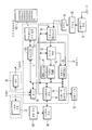
도 1은 본 발명을 지원하도록 구성된 예시적인 홈 엔터테인먼트 시스템의 블럭도이다.
도 2는 본 발명의 바람직한 윤곽화 검출 테스트의 플로우챠트이다.
도 3은 본 발명의 대체 윤곽화 검출 테스트의 플로우챠트이다.
도 4는 본 발명의 윤곽화 감소 기술의 플로우챠트이다.
도 5는 본 발명의 대체 윤곽화 감소 기술의 플로우챠트이다.
도 6은 본 발명의 또다른 대체 윤곽화 감소 기술의 플로우챠트이다.
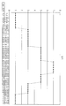
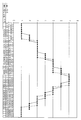
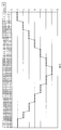
도 7은 입력 화소 성분 값의 예시적인 시퀀시를 나타내는 그래프이다.
도 8은 도 7의 입력 화소 성분 값과 도 5의 윤곽화 감소 프로세스에 의해 생성된 출력 화소 성분 값의 비교를 나타내는 그래프이다.
도 9는 도 7의 입력 화소 성분 값과 도 4의 윤곽화 감소 프로세스에 의해 생성된 출력 화소 성분 값의 비교를 나타내는 그래프이다.
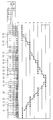
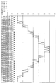
도 10은 입력 화소 성분 값의 또다른 예시적인 시퀀스를 설명하는 그래프이다.
도 11은 도 10의 입력 화소 성분 값과 도 6의 윤곽화 감소 처리에 의해 생성된 출력 화소 성분 값의 비교를 나타내는 그래프이다.1 is a block diagram of an exemplary home entertainment system configured to support the present invention.
2 is a flowchart of a preferred contour detection test of the present invention.
3 is a flowchart of an alternate contour detection test of the present invention.
4 is a flowchart of the contour reduction technique of the present invention.
5 is a flowchart of an alternate contour reduction technique of the present invention.
6 is a flowchart of another alternative contour reduction technique of the present invention.
7 is a graph illustrating an exemplary sequence of input pixel component values.
FIG. 8 is a graph illustrating a comparison between the input pixel component value of FIG. 7 and the output pixel component value generated by the contour reduction process of FIG. 5.
FIG. 9 is a graph illustrating a comparison of an input pixel component value of FIG. 7 and an output pixel component value generated by the contour reduction process of FIG. 4.
10 is a graph illustrating another exemplary sequence of input pixel component values.
FIG. 11 is a graph showing a comparison between the input pixel component value of FIG. 10 and the output pixel component value generated by the contour reduction process of FIG. 6.
본 발명의 특징 및 장점은 예시로 나타낸 다음의 설명으로부터 더욱 명백하게 될 것이다.The features and advantages of the present invention will become more apparent from the following description, which is illustrated by way of example.
도 1을 참조하면, 본 발명의 원리에 따라 동작하는 예시적인 디지털 비디오 수신 시스템의 블럭도가 도시되어 있다. 비디오 수신기 시스템은 오디오, 비디오 및 관련 데이터를 전달하는 신호로 변조되는 브로드캐스트 캐리어를 수신 및 디지털화하기 위한 안테너(10) 및 입력 프로세서(15)와, 입력 프로세서(15)로부터의 디지털 출력 신호를 수신 및 복조하기 위한 복조기(20)와, 격자 디코딩되어 바이트 길이 데이터 세그먼트로 맵핑되고 디인터리브되어 리드-솔로몬(Reed-Solomon) 에러 정정된 신호를 출력하는 디코더(30)를 포함한다. 디코더(30)로부터의 정정된 출력 데이터는 프로그램 표시 멀티플렉스된 오디오, 비디오 및 데이터 성분을 포함하는 MPEG 호환가능한 전송 데이터 스트림의 형태로 되어 있다.1, a block diagram of an exemplary digital video receiving system operating in accordance with the principles of the present invention is shown. The video receiver system includes an
비디오 수신기 시스템은 전화선을 통해 서버(83) 또는 접속 서비스(87)에 접속될 수 있는 모뎀(80)을 더 포함하여, 다양한 포맷(예를 들어, MPEG, HTML 및/또는 JAVA)의 데이터가 전화선을 통해 비디오 수신기 시스템에 의해 수신될 수 있게 한다.The video receiver system further includes a
프로세서(25)는 디코더(30) 및/또는 모뎀(80)으로부터의 데이터 출력을 처리하여, 이 처리된 데이터가 사용자에 의해 원격 제어 유닛(125)을 통해 입력된 요구에 따라 디스플레이 유닛(75) 상에 표시되거나 저장 매체(105) 상에 저장될 수 있게 한다. 특히, 프로세서(25)는 원격 유닛 인터페이스(120)를 통해 원격 제어 유닛(125)으로부터 수신된 요구를 해석하고 사용자의 요구를 실행할 프로세서(25)의 요소(예를 들어, 채널, 웹사이트, 및/또는 온-스크린 디스플레이(OSD))를 적당히 구성하는 컨트롤러(115)를 포함한다. 하나의 예시적인 모드에서, 컨트롤러(115)는 MPEG 디코딩된 데이터를 제공하는 프로세서(25)의 요소 및 디스플레이 유닛(75)상의 표시를 위한 OSD를 구성한다. 다른 예시적인 모드에서, 컨트롤러(115)는 저장 디바이스(90) 및 저장 인터페이스(95)를 거쳐 저장 매체(105) 상에 저장하기 위해 MPEG 호환가능한 데이터 스트림을 제공하는 프로세서(25)의 요소를 구성한다. 또다른 예시적인 모드에서, 컨트롤러(115)는 서버(83) 또는 접속 서비스(87)를 통한 양방향(예를 들어, 인터넷) 통신을 수신하기 위해서와 같이, 다른 통신 모드를 위한 프로세서(25)의 요소를 구성한다.The
프로세서(25)는 전송 스트림에서 선택된 패킷을 식별하여 디코더(30)로부터 전송 디코더(55)로 라우팅하는 디코딩 PID 선택 유닛(45)을 포함한다. 디코더(30)로부터의 전송 스트림은 이하에서 더욱 상세하게 설명되는 바와 같이, 전송 디코더(55)에 의해 오디오, 비디오 및 데이터 성분으로 디멀티플렉스되어 프로세서(25)의 다른 요소에 의해 추가로 처리되게 된다.
프로세서(25)에 제공된 전송 스트림은 프로그램 채널 데이터, 보조 시스템 타이밍 정보, 그리고 프로그램 컨텐츠 레이팅, 프로그램 종횡비, 및 프로그램 가이드 정보 등의 프로그램 특정 정보를 포함하는 데이터 패킷으로 이루어진다. 전송 디코더(55)는 보조 정보 패킷을, 보조 정보를 계층적으로 배열된 테이블로 파싱(parse), 조합(collate) 및 어셈블리하는 컨트롤러(115)에 보낸다. 사용자 선택 프로그램 채널로 이루어진 개별적인 데이터 패킷은 어셈블리된 프로그램 특정 정보를 이용하여 식별되어 어셈블리된다. 시스템 타이밍 정보는 시간 기준 표시자 및 관련 정정 데이터(예를 들어, 서머타임(daylight saving) 시간 표시자, 및 시간 편차(time drift), 윤년 등의 조정을 위한 오프셋 정보)를 포함한다. 이 타이밍 정보는 디코더가 시간 기준 표시자를 프로그램의 브로드캐스터에 의해 앞으로의 프로그램 전송을 위한 날짜와 시간을 정하기 위한 타임 클럭(예를 들어, 미국 동부 연안 시간 및 날짜)으로 변환시키면 충분하다. 타임 클럭은 프로그램 재생, 프로그램 녹화, 및 프로그램 녹화 재생 등의 스케줄된 프로그램 처리 기능을 초기화하는 데에 이용 가능하다. 또한, 프로그램 특정 정보는 도 1의 시스템으로 하여금 완성 프로그램을 형성하도록 원하는 채널로 튜닝하여 데이터 패킷을 어셈블리할 수 있게 하는 조건부 억세스, 네트워크 정보, 및 식별과 링크 데이터를 포함한다.The transport stream provided to the
전송 디코더(55)는 MPEG 호환 가능 비디오, 오디오 및 서브픽쳐 스트림을 MPEG 디코더(65)로 제공한다. 비디오 및 오디오 스트림은 선택된 채널 프로그램 컨텐츠를 나타내는 압축 비디오 및 오디오 데이터를 포함한다. 서브픽쳐 데이터는 레이팅 정보, 프로그램 설명 정보 등의 채널 프로그램 컨텐츠와 관련되는 정보를 포함한다.The
MPEG 디코더(65)는 랜덤 억세스 메모리(RAM)(67)와 협동하여 유닛(65)으로부터의 MPEG 호환 가능 패킷화 오디오 및 비디오 데이터를 디코딩 및 압축 해제하고, 이 압축 해제된 프로그램 표시 화소 데이터를 디스플레이 프로세서(70)에 제공한다. 디코더(65)는 유닛(55)으로부터의 서브 픽쳐 데이터를 어셈블리, 조합 및 해석하여 내부 OSD 모듈(도시 생략함)에 출력되도록 포맷된 프로그램 가이드 데이터를 생성한다. OSD 모듈은 RAM(67)과 협동하여 서브 픽쳐 데이터 및 그 외 정보를 처리하여, 디스플레이 디바이스(75) 상에 표시하는 선택 가능한 메뉴 옵션 및 기타 정보를 포함하는, 서브타이틀링(substitling), 제어 및 정보 메뉴 디스플레이를 나타내는 화소 맵핑된 데이터를 생성한다. 표시되는 제어 및 정보 메뉴는 사용자가 선택된 프로그램을 수신하게 튜닝하여 시청하고, 저장 매체(105) 상에 이 프로그램을 녹화하고, 매체(105)로부터 이 프로그램을 재생하는 것을 포함하는, 앞으로의 프로그램 처리 기능을 보고 스케줄하기 위한 프로그램을 선택할 수 있게 한다.The
OSD 모듈(도시 생략)에 의해 생성된 텍스트 및 그래픽을 포함하는, 제어 및 정보 디스플레이는 컨트롤러(115)의 지시하에서 오버레이 화소 맵 데이터의 형태로 생성되게 된다. OSD 모듈로부터의 오버레이 화소 맵 데이터는 컨트롤러(115)의 지시하에서 MPEG 디코더(65)로부터의 압축 해제된 화소 표시 데이터와 조합되어 동기화된다. 관련된 서브 픽쳐 데이터와 함께 선택된 채널 상의 비디오 프로그램을 나타내는 조합된 화소 맵 데이터가 디스플레이 프로세서(70)에 의해 인코딩되어 디바이스(75)에 출력되어 표시된다.Control and information displays, including text and graphics generated by an OSD module (not shown), are generated in the form of overlay pixel map data under the direction of the
본 발명의 원리는 코딩 타입이나 변조 포맷이 다양할 수 있는 지상, 케이블, 위성, DSL, 인터넷 또는 컴퓨터 네트워크 브로드캐스트 시스템에 적용될 수 있다. 이 시스템은 예를 들어, 다른 유형의 인코딩된 데이터 스트림 및 프로그램 특정 정보를 이송하는 다른 방법과 관련되는 non-MPEG 호환 가능한 시스템을 포함할 수 있다. 또한, 개시된 시스템이 브로드캐스트 프로그램을 처리하는 것으로 기재되어 있지만, 이는 오직 예시적인 것이다. 도 1의 아키텍쳐는 배타적이지 않다. 다른 아키텍쳐가 본 발명의 원리에 따라서 동일한 목적을 성취하도록 유도될 수 있다.The principles of the present invention can be applied to terrestrial, cable, satellite, DSL, Internet or computer network broadcast systems, which may vary in coding type or modulation format. The system may include, for example, a non-MPEG compatible system that is associated with other types of encoded data streams and other ways of transferring program specific information. In addition, although the disclosed system is described as processing a broadcast program, this is only exemplary. The architecture of FIG. 1 is not exclusive. Other architectures may be induced to achieve the same purpose in accordance with the principles of the present invention.
일반적으로, 도 2 내지 도 6은 본 발명의 윤곽화 검출 및 감소 프로세스를 설명한다. 본 발명의 프로세스는 화소 단위로, 화소의 미리 정해진 스팬(예를 들어, 일차원의 수평 및/또는 수직 화소 스팬, 이차원의 장방형 화소 스팬이나 원형 화소 스팬 등의 다차원 화소 스팬, 또는 당업자에게 알려진 다른 화소 스팬)의 성분 값(예를 들어, 레드(R), 그린(G), 및 블루(B) 성분 값)에 적용되는 것이 바람직하며, 디스플레이 프로세서(70)의 프로그램된 명령 내에서 전체적으로나 부분적으로 실행될 수 있다. 다르게는, 본 발명의 프로세스는 윤곽화 검출 및 감소 회로(도시 생략) 내에서 하드웨어로 구현될 수 있다.In general, Figures 2-6 illustrate the contour detection and reduction process of the present invention. The process of the present invention is performed on a pixel-by-pixel basis, with a predetermined span of pixels (e.g., one-dimensional horizontal and / or vertical pixel spans, two-dimensional rectangular pixel spans or circular pixel spans, or other pixels known to those skilled in the art). Span), for example, red (R), green (G), and blue (B) component values), preferably in whole or in part within the programmed instructions of the
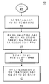
이제 도 2를 참조하면, 본 발명의 바람직한 윤곽화 검출 프로세스(200)가 도시되어 있다. 기동시, 디스플레이 프로세서(70)는 단계(205)에서, 화소 성분 값들의 미리 정해진 스팬(예를 들어, 8화소 스팬)을 식별한다. 미리 정해진 화소 스팬이 식별된 후에, 디스플레이 프로세서(70)는 단계(210)에서, 미리 정해진 화소 스팬의 최대 및 최소의 화소 성분 값을 결정한다. 다음에, 단계(215)에서, 디스플레이 프로세서(70)는 최대 성분 값에서 최소 성분 값을 뺀 값이 미리 정해진 임계치 "N"보다 작은지를 결정한다. "N"으로 선택되는 값은 수신된 비디오 신호에 대해 보호되고/되거나 이에 존재하고 있는 것으로 예상되는 윤곽화에 의존한다. 예를 들어, 수신된 비디오 신호의 모든 상태 또는 화상 신호 값이 사용되고 있는 것으로 예상되고 윤곽화가 여전히 예측되면, "N"을 2로 설정하는 것이 적합하다. 그러나, 모든 제3 상태나 화상 값이 사용되고 있는 것으로(즉, 비사용 상태나 화상 값이 있다) 예상되면, "N"을 4로 설정하는 것이 더욱 적합한 선택이 된다. 최대 성분 값에서 최소 성분 값을 뺀 값이 미리 정해진 임계 값 "N"보다 작지 않으면, 프로세서(70)는 단계(220)에서 미리 정해진 화소 스팬의 중심(또는 중심 근처) 화소 성분 값을 변경하지 않는다(예를 들어, 8화소 스팬의 네 번째 화소 성분 값은 변경되지 않는다). 최대 성분 값에서 최소 성분 값을 뺀 값이 미리 정해진 임계 값 "N"보다 작으면, 프로세서(70)는 단계(225)에서 이하 더욱 상세히 설명되는 바와 같이, 도 4, 도 5 또는 도 6의 윤곽화 감소 프로세스에 따라서 중심(또는 중심 근처) 화소 값을 교체한다.Referring now to FIG. 2, a preferred
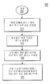
이하 도 3을 참조하면, 본 발명의 대안적인 윤곽화 검출 프로세스(300)가 도시되어 있다. 기동시, 디스플레이 프로세서(70)는 단계(305)에서, 화소 성분 값의 미리 정해진 스팬(예를 들어, 8 화소 스팬)을 식별한다. 그 후에, 단계(310)에서, 프로세서(70)는 미리 정해진 화소 스팬에 걸쳐 실행중인 화소 성분 값의 합을 연산한다. 다음에, 단계(315)에서, 프로세서(70)는 미리 정해진 화소 스팬(예를 들어, 8화소)의 중심이나 그 근처의 화소 성분 값(예를 들어, 네 번째 화소 성분 값)에 화소 스팬의 화소 성분 값의 총수(예를 들어, 8)를 곱한다. 프로세서(70)는 단계(320)에서, 곱해진 화소 성분 값과 화소 성분 값의 합 간의 차이의 절대값을 연산한다. 다음에, 프로세서(70)는 단계(325)에서, 연산된 차이의 절대값이 미리 정해진 범위 내에 있는지를 결정한다. 하나의 예시적인 범위는 연산된 차이의 절대값이 3보다 크고 9보다 작은 경우이다. 범위 내에 있지 않으면, 프로세서(70)는 단계(330)에서 중심 화소 값을 변경하지 않는다. 범위 내에 있으면, 프로세서(70)는 단계(335)에서 이하 더욱 상세히 설명되는 바와 같이, 도 4, 도 5 또는 도 6의 윤곽화 감소 프로세스에 따라서 중심(또는 중심 근처) 화소 값을 교체한다.Referring now to FIG. 3, an alternative contour detection process 300 of the present invention is shown. Upon startup, the
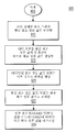
이하 도 4를 참조하면, 본 발명의 윤곽화 감소 프로세스(400)가 도시되어 있다. 도 2의 크기 차이 테스트 또는 도 3의 평균 테스트가 통과되었다고 결정된 후에, 프로세서(70)는 단계(405)에서 윤곽화 감소 프로세스(400)의 실행을 초기화한다. 먼저, 프로세서(70)는 단계(410)에서 미리 정해진 화소 스팬의 평균 화소 성분 값을 연산한다. 다음에, 프로세서(70)는 단계(415)에서 평균 화소 성분 값을 미리 정해진 비트 폭(즉, 화소 성분 값의 본래의 비트 폭에 부가적인 최소 유효 비트(LSB)의 수를 더함)으로 환산한다(예를 들어, 반올림하거나 버린다). 그 후, 프로세서(70)는 단계(420)에서, 중심이나 중심 근처의 화소 성분 값(예를 들어, 8화소 스팬의 네 번째 화소 값)을 환산된 평균 값으로 교체한다. 프로세서(70)는 단계(425)에서, 윤곽화 검출 프로세스(200)(도 2에 나타냄) 및/또는 윤곽화 검출 프로세스(300)(도 3에 나타냄)에 따라서 다음 화소 성분 값을 테스트한다. 입력 화소 성분 값의 예시적인 시퀀스(도 7에 나타냄)와 윤곽화 감소 프로세스(400)에 의해 생성된 출력 화소 성분 값의 시퀀스 간의 그래프에 의한 비교를 도 9에 나타내며, 여기에서 단일의 LSB가 부가된다.Referring now to FIG. 4, an
이하 도 5를 참조하면, 본 발명의 대체의 윤곽화 감소 프로세스(500)가 도시되어 있다. 도 2의 크기 차이 테스트 또는 도 3의 평균 테스트를 통과했는지를 결정한 후에, 프로세스(70)는 단계(505)에서 윤곽화 감소 프로세스(500)의 실행을 초기화한다. 먼저, 프로세서(70)는 단계(510)에서 미리 정해진 화소 스팬의 평균 화소 성분 값을 연산한다. 그 후, 프로세서(70)는 단계(515)에서 새로운 화소 성분 값을 생성하도록 평균 값을 가장 근접한 정수로 환산한다(예를 들어, 반올림하거나 버린다). 다음에, 프로세서(70)는 단계(520)에서 중심이나 중심 근처의 화소 성분 값(예를 들어, 8화소 스팬의 네 번째 화소 값)을 환산된 평균 화소 성분 값으로 교체한다. 프로세서(70)는 단계(525)에서, 윤곽화 검출 프로세스(200)(도 2에 나타냄) 및/또는 윤곽화 검출 프로세스(300)(도 3에 나타냄)에 따라서 다음 화소 성분 값을 테스트한다. 입력 화소 성분 값(도 7에 나타냄)의 예시적인 시퀀스와 윤곽화 감소 프로세스(500)에 의해 생성된 출력 화소 성분 값의 시퀀스의 그래프를 통한 비교를 도 8에 나타낸다.Referring now to FIG. 5, an alternate
이하 도 6을 참조하면, 본 발명의 다른 대안적인 윤곽화 감소 프로세스(600)가 도시되어 있다. 도 2의 크기 차이 테스트 또는 도 3의 평균 테스트를 통과했는지를 결정한 후에, 프로세서(70)는 단계(605)에서 윤곽화 감소 프로세스(600)의 실행을 초기화한다. 먼저, 프로세서(70)는 단계(610)에서 미리 정해진 화소 스팬의 평균 화소 성분 값을 연산한다. 예를 들어, 8화소 스팬의 각 화소 성분 값의 비트 폭이 8비트이면, 평균 화소 성분 값의 비트 폭은 11비트가 된다. 그 후, 프로세서(70)는 단계(615)에서, 디더(dither) 신호를 평균에 부가하여 새로운 화소 성분 값을 생성한다. 디더 신호는 1과 0이 교대하는 스트링(예를 들어, 1, 0, 1, 0, 1, 0...) 등의 교대 신호일 수 있거나, 디더링 신호는 당업자에게 잘 알려진 바와 같이, 반복 반올림 회로로 구현될 수 있지만, 이에 제한되지는 않는다. 예를 들어, 1과 0이 교대하는 두 상태의 디더 신호는 9비트의 합산기를 이용하여 11비트 평균에 부가될 수 있다. 이를 행하기 위해서 11비트 평균은 11비트 평균의 두 LSB를 버린 다음, 두 상태의 디더 신호를 (9비트 합산기를 통해) 9비트 평균의 최소 유효 비트에 부가함으로써 9비트 평균으로 버림을 행한다. 다른 접근법으로, 두 상태의 디더 신호가 11비트 합산기를 이용하여 11비트 평균에 부가될 수 있다. 그렇게 행하기 위해서 두 상태의 디더 신호가 (11비트 가산기를 통해) 11비트 평균의 세 번째 LSB에 부가된다. 다음에, 프로세서(70)는 단계(620)에서, 디더링된 화소 성분 값을 원하는 비트 폭(예를 들어, 화소 성분 값의 원래 비트 폭)으로 버림을 행한다. 예를 들어, 9비트 디더 평균은 LSB를 제거하여 8비트 디더 평균으로 버림을 행하거나 11비트 디더 신호는 세 개의 LSB를 제거하여 8비트 디더 평균으로 버림을 행한다. 그 후에, 프로세서(70)는 단계(625)에서 중심이나 그 근처의 화소 성분 값(예를 들어, 8화소 스팬의 네 번째 화소 값)을 버림을 행한 화소 성분 값으로 교체한다. 프로세서(70)는 단계(630)에서 윤곽화 검출 프로세스(200)(도 2에 도시됨) 및/또는 윤곽화 검출 프로세스(300)(도 3에 도시됨)에 따라서 다음 화소 성분 값을 테스트한다. 입력 화소 성분 값(도 10에 도시됨)의 예시적인 시퀀스와 윤곽화 감소 프로세스(600)에 의해 생성된 출력 화소 성분 값의 시퀀스의 그래프를 통한 비교를 도 11에 나타낸다.Referring now to FIG. 6, another
본 발명을 바람직한 실시예에 따라서 설명하였지만, 첨부한 청구의 범위에 의해 정의된 바와 같이, 본 발명의 정신과 범위로부터 벗어나지 않고 실시예에 여러 변경을 행할 수 있다는 것이 명백하다.
Although the present invention has been described in accordance with preferred embodiments, it is apparent that various changes may be made to the embodiments without departing from the spirit and scope of the invention as defined by the appended claims.
Claims (2)
복수의 화소를 포함하는 비디오 신호를 수신하는 단계;
미리 정해진 수의 화소들을 포함하는 화소 스팬을 상기 수신된 비디오 신호에서 식별하는 단계;
상기 식별된 화소 스팬에서 최대 화소 값과 최소 화소 값을 검출하는 단계;
상기 최대 화소 값과 상기 최소 화소 값 간의 차이를 연산하는 단계;
상기 연산된 차이가 미리 정해진 임계 값보다 작은 경우 상기 식별된 화소 스팬에 상기 윤곽화 아티팩트들이 존재한다고 결정하는 단계; 및
상기 윤곽화 아티팩트들이 감소되도록 상기 식별된 화소 스팬의 상기 화소들을 처리하는 단계를 포함하는 방법. In the method for reducing the contouring artifacts in the image display,
Receiving a video signal comprising a plurality of pixels;
Identifying in the received video signal a pixel span comprising a predetermined number of pixels;
Detecting a maximum pixel value and a minimum pixel value in the identified pixel span;
Calculating a difference between the maximum pixel value and the minimum pixel value;
Determining that the contouring artifacts are present in the identified pixel span when the calculated difference is less than a predetermined threshold value; And
Processing the pixels of the identified pixel span such that the contouring artifacts are reduced.
복수의 화소를 포함하는 비디오 신호를 수신하기 위한 수단;
미리 정해진 수의 화소들을 포함하는 화소 스팬을 상기 수신된 비디오 신호에서 식별하기 위한 수단;
상기 식별된 화소 스팬의 최대 화소 값과 최소 화소 값을 검출하기 위한 수단;
상기 최대 화소 값과 상기 최소 화소 값 간의 차이를 연산하기 위한 수단;
상기 연산된 차이가 미리 정해진 임계 값보다 작은 경우 상기 식별된 화소 스팬에 윤곽화 아티팩트들이 존재한다고 결정하기 위한 수단; 및
상기 윤곽화 아티팩트들이 감소되도록 상기 식별된 화소 스팬의 상기 화소들을 처리하기 위한 수단을 포함하는 시스템.
A system for reducing contouring artifacts in image display, comprising:
Means for receiving a video signal comprising a plurality of pixels;
Means for identifying a pixel span comprising a predetermined number of pixels in the received video signal;
Means for detecting a maximum pixel value and a minimum pixel value of the identified pixel span;
Means for calculating a difference between the maximum pixel value and the minimum pixel value;
Means for determining that contouring artifacts are present in the identified pixel span when the calculated difference is less than a predetermined threshold value; And
Means for processing the pixels of the identified pixel span such that the contouring artifacts are reduced.
Applications Claiming Priority (2)
| Application Number | Priority Date | Filing Date | Title |
|---|---|---|---|
| US10/056,595 US6647152B2 (en) | 2002-01-25 | 2002-01-25 | Method and system for contouring reduction |
| US10/056,595 | 2002-01-25 |
Related Parent Applications (1)
| Application Number | Title | Priority Date | Filing Date |
|---|---|---|---|
| KR1020047011454A Division KR101000718B1 (en) | 2002-01-25 | 2003-01-17 | Method and system for contouring reduction |
Publications (1)
| Publication Number | Publication Date |
|---|---|
| KR20100089906A true KR20100089906A (en) | 2010-08-12 |
Family
ID=27609300
Family Applications (2)
| Application Number | Title | Priority Date | Filing Date |
|---|---|---|---|
| KR1020107016890A KR20100089906A (en) | 2002-01-25 | 2003-01-17 | Method and system for contouring reduction |
| KR1020047011454A KR101000718B1 (en) | 2002-01-25 | 2003-01-17 | Method and system for contouring reduction |
Family Applications After (1)
| Application Number | Title | Priority Date | Filing Date |
|---|---|---|---|
| KR1020047011454A KR101000718B1 (en) | 2002-01-25 | 2003-01-17 | Method and system for contouring reduction |
Country Status (10)
| Country | Link |
|---|---|
| US (1) | US6647152B2 (en) |
| EP (1) | EP1468397A4 (en) |
| JP (1) | JP4740539B2 (en) |
| KR (2) | KR20100089906A (en) |
| CN (1) | CN1307592C (en) |
| BR (1) | BR0307078A (en) |
| MX (1) | MXPA04007139A (en) |
| MY (1) | MY134337A (en) |
| TW (1) | TW591936B (en) |
| WO (1) | WO2003065293A1 (en) |
Cited By (1)
| Publication number | Priority date | Publication date | Assignee | Title |
|---|---|---|---|---|
| KR20140076053A (en) * | 2012-12-12 | 2014-06-20 | 엘지디스플레이 주식회사 | Display device and image data processing method thereof |
Families Citing this family (38)
| Publication number | Priority date | Publication date | Assignee | Title |
|---|---|---|---|---|
| US6885383B2 (en) * | 2002-03-08 | 2005-04-26 | David Muresan | Moving-pixels procedure for digital picture edge-smoothing |
| EP1387340A1 (en) * | 2002-07-30 | 2004-02-04 | Deutsche Thomson-Brandt Gmbh | Method and device for processing video data for a display |
| JP2004078059A (en) * | 2002-08-22 | 2004-03-11 | Rohm Co Ltd | Display device |
| JP3877694B2 (en) * | 2003-03-28 | 2007-02-07 | 三洋電機株式会社 | Display processing device |
| US7602851B2 (en) | 2003-07-18 | 2009-10-13 | Microsoft Corporation | Intelligent differential quantization of video coding |
| US7738554B2 (en) | 2003-07-18 | 2010-06-15 | Microsoft Corporation | DC coefficient signaling at small quantization step sizes |
| US8218624B2 (en) | 2003-07-18 | 2012-07-10 | Microsoft Corporation | Fractional quantization step sizes for high bit rates |
| US10554985B2 (en) | 2003-07-18 | 2020-02-04 | Microsoft Technology Licensing, Llc | DC coefficient signaling at small quantization step sizes |
| US7580584B2 (en) | 2003-07-18 | 2009-08-25 | Microsoft Corporation | Adaptive multiple quantization |
| US7801383B2 (en) | 2004-05-15 | 2010-09-21 | Microsoft Corporation | Embedded scalar quantizers with arbitrary dead-zone ratios |
| US7542620B1 (en) * | 2004-08-16 | 2009-06-02 | Apple Inc. | Robust temporal dithering and filtering |
| US7675872B2 (en) * | 2004-11-30 | 2010-03-09 | Broadcom Corporation | System, method, and apparatus for displaying pictures |
| KR100594738B1 (en) * | 2004-12-28 | 2006-06-30 | 삼성전자주식회사 | Apparatus for removing contour caused by reducing bit depth |
| JP4463705B2 (en) | 2005-03-01 | 2010-05-19 | 三菱電機株式会社 | Image display device and image display method |
| US8422546B2 (en) | 2005-05-25 | 2013-04-16 | Microsoft Corporation | Adaptive video encoding using a perceptual model |
| KR100627615B1 (en) * | 2005-12-29 | 2006-09-25 | 엠텍비젼 주식회사 | Apparatus for removing color interpolation by using adjustable threshold |
| JP4455513B2 (en) * | 2006-02-13 | 2010-04-21 | 三菱電機株式会社 | Image processing method, image processing apparatus, and image display apparatus |
| KR20070099170A (en) * | 2006-04-03 | 2007-10-09 | 엘지.필립스 엘시디 주식회사 | Apparatus and method for driving data, apparatus and method for driving of image display device using the same |
| US8130828B2 (en) | 2006-04-07 | 2012-03-06 | Microsoft Corporation | Adjusting quantization to preserve non-zero AC coefficients |
| US7974340B2 (en) | 2006-04-07 | 2011-07-05 | Microsoft Corporation | Adaptive B-picture quantization control |
| US7995649B2 (en) | 2006-04-07 | 2011-08-09 | Microsoft Corporation | Quantization adjustment based on texture level |
| US8059721B2 (en) | 2006-04-07 | 2011-11-15 | Microsoft Corporation | Estimating sample-domain distortion in the transform domain with rounding compensation |
| US8503536B2 (en) | 2006-04-07 | 2013-08-06 | Microsoft Corporation | Quantization adjustments for DC shift artifacts |
| US8711925B2 (en) | 2006-05-05 | 2014-04-29 | Microsoft Corporation | Flexible quantization |
| US8269886B2 (en) * | 2007-01-05 | 2012-09-18 | Marvell World Trade Ltd. | Methods and systems for improving low-resolution video |
| CA2675758C (en) * | 2007-01-19 | 2015-05-19 | Thomson Licensing | Reducing contours in digital images |
| US8238424B2 (en) | 2007-02-09 | 2012-08-07 | Microsoft Corporation | Complexity-based adaptive preprocessing for multiple-pass video compression |
| US8498335B2 (en) | 2007-03-26 | 2013-07-30 | Microsoft Corporation | Adaptive deadzone size adjustment in quantization |
| US8243797B2 (en) | 2007-03-30 | 2012-08-14 | Microsoft Corporation | Regions of interest for quality adjustments |
| US7864191B2 (en) * | 2007-04-16 | 2011-01-04 | Texas Instruments Incorporated | Techniques for efficient dithering |
| US8442337B2 (en) | 2007-04-18 | 2013-05-14 | Microsoft Corporation | Encoding adjustments for animation content |
| US8331438B2 (en) | 2007-06-05 | 2012-12-11 | Microsoft Corporation | Adaptive selection of picture-level quantization parameters for predicted video pictures |
| US8189933B2 (en) | 2008-03-31 | 2012-05-29 | Microsoft Corporation | Classifying and controlling encoding quality for textured, dark smooth and smooth video content |
| US8897359B2 (en) | 2008-06-03 | 2014-11-25 | Microsoft Corporation | Adaptive quantization for enhancement layer video coding |
| US8270498B2 (en) * | 2009-03-26 | 2012-09-18 | Apple Inc. | Dynamic dithering for video compression |
| US8860750B2 (en) * | 2011-03-08 | 2014-10-14 | Apple Inc. | Devices and methods for dynamic dithering |
| US9092856B2 (en) * | 2013-10-31 | 2015-07-28 | Stmicroelectronics Asia Pacific Pte. Ltd. | Recursive de-banding filter for digital images |
| CN108322723B (en) * | 2018-02-06 | 2020-01-24 | 深圳创维-Rgb电子有限公司 | Color distortion compensation method and device and television |
Family Cites Families (33)
| Publication number | Priority date | Publication date | Assignee | Title |
|---|---|---|---|---|
| JPS605692A (en) | 1983-06-24 | 1985-01-12 | Victor Co Of Japan Ltd | Video signal processing device |
| JPS6319982A (en) * | 1986-07-12 | 1988-01-27 | Fujitsu Ltd | Gradation control system for video printer |
| US5838298A (en) | 1987-02-13 | 1998-11-17 | Canon Kabushiki Kaisha | Image processing apparatus and method for smoothing stairway-like portions of a contour line of an image |
| JP2644491B2 (en) * | 1987-05-18 | 1997-08-25 | キヤノン株式会社 | Image processing device |
| US5138303A (en) | 1989-10-31 | 1992-08-11 | Microsoft Corporation | Method and apparatus for displaying color on a computer output device using dithering techniques |
| JPH03226177A (en) * | 1990-01-31 | 1991-10-07 | Fuji Xerox Co Ltd | Gradation conversion processing unit |
| US5218649A (en) * | 1990-05-04 | 1993-06-08 | U S West Advanced Technologies, Inc. | Image enhancement system |
| US5374963A (en) | 1990-06-01 | 1994-12-20 | Thomson Consumer Electronics, Inc. | Picture resolution enhancement with dithering and dedithering |
| JPH0490680A (en) * | 1990-08-06 | 1992-03-24 | Oki Electric Ind Co Ltd | Picture binarizing method |
| JPH04165874A (en) * | 1990-10-30 | 1992-06-11 | Canon Inc | Digital signal processor |
| US5101452A (en) | 1990-12-17 | 1992-03-31 | Eastman Kodak Company | Apparatus and method for dynamic step quantization |
| DE69324513T2 (en) * | 1992-02-11 | 1999-10-21 | Eastman Kodak Co | Image production system and associated method for minimizing contours for a quantized digital color image |
| JP3222183B2 (en) * | 1992-02-19 | 2001-10-22 | 株式会社リコー | Image processing device |
| JPH06152992A (en) * | 1992-10-29 | 1994-05-31 | Canon Inc | Picture processing method and device |
| JPH06225179A (en) * | 1993-01-21 | 1994-08-12 | Sony Corp | Quantizer for picture signal |
| JP3361355B2 (en) * | 1993-05-14 | 2003-01-07 | 株式会社リコー | Image processing device |
| US5651078A (en) * | 1994-07-18 | 1997-07-22 | Thomson Consumer Electronics, Inc. | Method and apparatus for reducing contouring in video compression |
| US6147671A (en) | 1994-09-13 | 2000-11-14 | Intel Corporation | Temporally dissolved dithering |
| KR100414432B1 (en) * | 1995-03-24 | 2004-03-18 | 마츠시타 덴끼 산교 가부시키가이샤 | Contour extraction device |
| US5579054A (en) * | 1995-04-21 | 1996-11-26 | Eastman Kodak Company | System and method for creating high-quality stills from interlaced video |
| JPH0944648A (en) * | 1995-08-01 | 1997-02-14 | Sony Corp | Image processing device and method therefor |
| US6040876A (en) | 1995-10-13 | 2000-03-21 | Texas Instruments Incorporated | Low intensity contouring and color shift reduction using dither |
| US5777624A (en) | 1996-01-02 | 1998-07-07 | Intel Corporation | Method and apparatus for eliminating visual artifacts caused by diffusing errors in a decimated video signal |
| JP4067594B2 (en) | 1996-01-26 | 2008-03-26 | テキサス インスツルメンツ インコーポレイテツド | Signal conversion circuit and method of converting input word to digital output word |
| US5835117A (en) * | 1996-05-31 | 1998-11-10 | Eastman Kodak Company | Nonlinear dithering to reduce neutral toe color shifts |
| FR2769453B1 (en) * | 1997-10-06 | 2000-01-07 | Telediffusion Fse | METHOD FOR EVALUATING THE DEGRADATION OF A VIDEO IMAGE INTRODUCED BY A CODING AND / OR STORAGE AND / OR DIGITAL TRANSMISSION SYSTEM |
| JPH11272228A (en) * | 1998-03-19 | 1999-10-08 | Mitsubishi Electric Corp | Display drive unit and method thereof |
| AU749885B2 (en) * | 1998-03-31 | 2002-07-04 | Bioreal, Inc. | Fine algae culture device |
| US6324310B1 (en) * | 1998-06-02 | 2001-11-27 | Digital Persona, Inc. | Method and apparatus for scanning a fingerprint using a linear sensor |
| JP3738574B2 (en) * | 1998-09-18 | 2006-01-25 | 富士ゼロックス株式会社 | Image information encoding device |
| JP2001036756A (en) * | 1999-07-15 | 2001-02-09 | Canon Inc | Method and device for processing image |
| JP2001136535A (en) * | 1999-08-25 | 2001-05-18 | Fuji Xerox Co Ltd | Image-encoding device and quantization characteristic determining device |
| JP2001092954A (en) * | 1999-09-20 | 2001-04-06 | Matsushita Electric Ind Co Ltd | Rounding processor |
-
2002
- 2002-01-25 US US10/056,595 patent/US6647152B2/en not_active Expired - Lifetime
-
2003
- 2003-01-17 JP JP2003564810A patent/JP4740539B2/en not_active Expired - Fee Related
- 2003-01-17 KR KR1020107016890A patent/KR20100089906A/en not_active Application Discontinuation
- 2003-01-17 WO PCT/US2003/001525 patent/WO2003065293A1/en active Application Filing
- 2003-01-17 CN CNB038026538A patent/CN1307592C/en not_active Expired - Fee Related
- 2003-01-17 EP EP03703878.3A patent/EP1468397A4/en not_active Withdrawn
- 2003-01-17 BR BR0307078-6A patent/BR0307078A/en not_active Application Discontinuation
- 2003-01-17 KR KR1020047011454A patent/KR101000718B1/en active IP Right Grant
- 2003-01-17 TW TW092101006A patent/TW591936B/en not_active IP Right Cessation
- 2003-01-17 MX MXPA04007139A patent/MXPA04007139A/en active IP Right Grant
- 2003-01-24 MY MYPI20030243A patent/MY134337A/en unknown
Cited By (1)
| Publication number | Priority date | Publication date | Assignee | Title |
|---|---|---|---|---|
| KR20140076053A (en) * | 2012-12-12 | 2014-06-20 | 엘지디스플레이 주식회사 | Display device and image data processing method thereof |
Also Published As
| Publication number | Publication date |
|---|---|
| TW591936B (en) | 2004-06-11 |
| KR20040075108A (en) | 2004-08-26 |
| MXPA04007139A (en) | 2004-10-29 |
| KR101000718B1 (en) | 2010-12-10 |
| EP1468397A1 (en) | 2004-10-20 |
| JP2005516260A (en) | 2005-06-02 |
| US6647152B2 (en) | 2003-11-11 |
| JP4740539B2 (en) | 2011-08-03 |
| US20030142878A1 (en) | 2003-07-31 |
| CN1623165A (en) | 2005-06-01 |
| BR0307078A (en) | 2004-12-28 |
| MY134337A (en) | 2007-12-31 |
| WO2003065293A1 (en) | 2003-08-07 |
| CN1307592C (en) | 2007-03-28 |
| TW200302662A (en) | 2003-08-01 |
| EP1468397A4 (en) | 2017-05-10 |
Similar Documents
| Publication | Publication Date | Title |
|---|---|---|
| KR101000718B1 (en) | Method and system for contouring reduction | |
| KR100334360B1 (en) | On-Screen Display Unit for Digital Video Signal Processing System | |
| US6480630B1 (en) | Encoding and decoding different resolution video signals for display on plural units | |
| US6400767B1 (en) | Communication of HBI data in digital television data streams | |
| KR100234839B1 (en) | Apparatus for recombining prioritized video data | |
| CN101248675B (en) | Broadcast receiving apparatus, broadcast receiving method and broadcast receiving circuit | |
| KR19990063541A (en) | Error correction coding method and apparatus, data transmission method, receiving method and apparatus | |
| CN1039764C (en) | Apparatus for concealing errors in digital video processing system | |
| EP1046281B1 (en) | Apparatus for providing a video lip sync delay and method therefore | |
| US6755531B2 (en) | Motion picture code evaluator and billing system | |
| KR101075969B1 (en) | Method and apparatus for preventing error propagation in a video sequence | |
| KR19990049348A (en) | FRAME RATE CONVERTER AND METHOD USING MOTION VECTOR. | |
| JP4674613B2 (en) | ISDB transmission device, ISDB transmission method, ISDB reception device, and ISDB reception method | |
| JP4674593B2 (en) | Image encoding device | |
| JP2009055231A (en) | Animation display processor, animation data multiplexer, animation display method, computer program, and recording medium | |
| JP2007215068A (en) | Image processing apparatus and method, and program | |
| MXPA00000345A (en) | A system for forming and processing program map information suitable for terrestrial, cable or satellite broadcast |
Legal Events
| Date | Code | Title | Description |
|---|---|---|---|
| A107 | Divisional application of patent | ||
| A201 | Request for examination | ||
| E902 | Notification of reason for refusal | ||
| E601 | Decision to refuse application |