US6147671A - Temporally dissolved dithering - Google Patents
Temporally dissolved dithering Download PDFInfo
- Publication number
- US6147671A US6147671A US08/305,262 US30526294A US6147671A US 6147671 A US6147671 A US 6147671A US 30526294 A US30526294 A US 30526294A US 6147671 A US6147671 A US 6147671A
- Authority
- US
- United States
- Prior art keywords
- values
- frame
- dither
- color
- digital video
- Prior art date
- Legal status (The legal status is an assumption and is not a legal conclusion. Google has not performed a legal analysis and makes no representation as to the accuracy of the status listed.)
- Expired - Lifetime
Links
Images

Classifications
-
- G—PHYSICS
- G09—EDUCATION; CRYPTOGRAPHY; DISPLAY; ADVERTISING; SEALS
- G09G—ARRANGEMENTS OR CIRCUITS FOR CONTROL OF INDICATING DEVICES USING STATIC MEANS TO PRESENT VARIABLE INFORMATION
- G09G5/00—Control arrangements or circuits for visual indicators common to cathode-ray tube indicators and other visual indicators
- G09G5/02—Control arrangements or circuits for visual indicators common to cathode-ray tube indicators and other visual indicators characterised by the way in which colour is displayed
Definitions
- This invention relates to digital video image processing, and more particularly to dithering in conversion of image data from a YUV-like format to an RGB format.
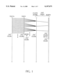
- FIG. 1 shows an entire color conversion process going from YUV24 to YUV9 to CLUT8 (i.e., RGB8) and then to RGB24 for display.
- FIG. 1 shows an entire color conversion process going from YUV24 to YUV9 to CLUT8 (i.e., RGB8) and then to RGB24 for display.
- FIG. 1 shows an entire color conversion process going from YUV24 to YUV9 to CLUT8 (i.e., RGB8) and then to RGB24 for display.
- FIG. 1 shows an entire color conversion process going from YUV24 to YUV9 to CLUT8 (i.e., RGB8) and then to RGB24 for display.
- FIG. 1 shows an entire color conversion process going from YUV24 to YUV9 to CLUT8 (i.e., RGB8) and then to RGB24 for display.
- FIG. 1 shows an entire color conversion process going from YUV24 to YUV9 to CLUT8 (i.e., RGB8) and then to RGB24 for display.
- Contouring is associated with the ability of the human visual system to perceive small changes in image intensity in areas of an image that have low spatial variation in image intensity. If an insufficient number of bits is used to represent intensities in such areas, the human visual system perceives the changes in intensity as happening in steps and not in a continuous manner. It is well known that one way to eliminate these contours is to use dithering of "near neighborhood" RGB8 colors. This is typically done using a fixed dithering matrix at amplitudes less than the step size of the Y intensity quantization being used on the Y values of each 4 ⁇ 4 block of pixels in a video frame.
- the dithering matrix is changed frame by frame. In this manner the same amount of dithering is accomplished with each frame, but different dithering patterns are used sequentially in time so that the tendency for perceivable graininess to occur is greatly reduced.
- the system designer can cause the time-averaged dither intensity at any and all pixel locations on a screen to be zero. This has the effect of "dissolving" any graininess artifacts observed--hence the name Temporally Dissolved Dithering (TDD).
- TDD Temporally Dissolved Dithering
- FIG. 1 depicts one example of a digital color conversion process.
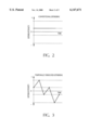
- FIG. 2 shows a conventional dithering intensity vs. time graph.
- FIG. 3 shows the time averaging-to-zero effect of Temporally Dissolved Dithering.
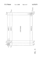
- FIG. 4 shows a typical digital video transmission system suitable for employing Temporally Dissolved Dithering.
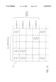
- FIG. 5 depicts a typical digital video frame.
- FIG. 6 depicts a 4 ⁇ 4 block in a digital video frame such as shown in FIG. 5.
- dithering is applied to 4 ⁇ 4 blocks of pixels sequentially throughout a frame of digital video YUV9 data.
- FIG. 5 shows such a frame divided into 30 bands and 40 columns of such 4 ⁇ 4 blocks of pixels.
- the first block of such a frame is depicted in FIG. 6.
- the Y values (which represent the intensity, i.e.
- any given block in the frame can have one of 2 16 different hues and each pixel in a block can have 2 8 different intensity levels, thus allowing for a total of 2 24 different possible "colors" for each pixel in a block.
- the dither matrices D, D1, D2, and D3 are then applied to each block of sequential frames of data in a repeating pattern frame by frame such as: (D, D1, D2, D3, D2, D1, D, D 1 , D 2 , - - - ) so that over time (i.e., as the frames are displayed sequentially in time) the time-averaged dither value at any pixel location is zero.
- FIGS. 2 and 3 The effect of use of the invention is demonstrated in FIGS. 2 and 3, wherein it is shown that conventional dithering results in an overall non-zero dithering bias, whereas TDD averages out to a zero dithering bias over time.
- FIG. 4 A typical digital video transmission system suitable for implementing the instant invention is shown in FIG. 4.
- the components shown are all known well to those skilled in the art, and can be implemented with standard equipment available from a variety of suppliers.
- Analog video source 400 transmits an analog video signal to a digitizer/processor/compressor 401 wherein the method of the instant invention is used as the digitized data is being processed. It is a "simple matter of programming" for one skilled in the art to write a program (suitable for the particular processor used) that accomplishes the method of the instant invention using the following example process:
- GIVEN a dither matrix D having N distinct dither levels.
- CONSTRUCTION Construct N-1 permutations of the given dither matrix D by successively cycling through the N dither levels at each location in the matrix. Denote these dither patterns by D1, D2, - - - , D(N-1).
- the data can be stored in memory 402 (optional) and later sent to transmitter 403 which sends the data along digital transmission path 404 to receiver 405 which in turn sends the data through decompressor/processor/digital-to-analog converter 406 and on to memory 407 (optional) for later viewing on video display 408.
- the implementation of the invention takes relatively little processing time (in addition to conventional dithering) but the resultant easily-recognizable image improvement is quite significant.
Abstract
Description
Claims (20)
Priority Applications (1)
| Application Number | Priority Date | Filing Date | Title |
|---|---|---|---|
| US08/305,262 US6147671A (en) | 1994-09-13 | 1994-09-13 | Temporally dissolved dithering |
Applications Claiming Priority (1)
| Application Number | Priority Date | Filing Date | Title |
|---|---|---|---|
| US08/305,262 US6147671A (en) | 1994-09-13 | 1994-09-13 | Temporally dissolved dithering |
Publications (1)
| Publication Number | Publication Date |
|---|---|
| US6147671A true US6147671A (en) | 2000-11-14 |
Family
ID=23180080
Family Applications (1)
| Application Number | Title | Priority Date | Filing Date |
|---|---|---|---|
| US08/305,262 Expired - Lifetime US6147671A (en) | 1994-09-13 | 1994-09-13 | Temporally dissolved dithering |
Country Status (1)
| Country | Link |
|---|---|
| US (1) | US6147671A (en) |
Cited By (19)
| Publication number | Priority date | Publication date | Assignee | Title |
|---|---|---|---|---|
| US20030164961A1 (en) * | 1999-10-22 | 2003-09-04 | Sharp Laboratories Of America, Inc. | Bit-depth extension with models of equivalent input visual noise |
| US6647152B2 (en) | 2002-01-25 | 2003-11-11 | Thomson Licensing S.A. | Method and system for contouring reduction |
| US6801213B2 (en) | 2000-04-14 | 2004-10-05 | Brillian Corporation | System and method for superframe dithering in a liquid crystal display |
| US6842184B2 (en) | 2002-12-03 | 2005-01-11 | Seiko Epson Corporation | Three dimensional stochastic screen for LCD and video |
| US20050068463A1 (en) * | 2003-09-30 | 2005-03-31 | Sharp Laboratories Of America, Inc. | Systems and methods for multi-dimensional dither structure creation and application |
| US20050174360A1 (en) * | 2002-02-01 | 2005-08-11 | Daly Scott J. | Methods and systems for adaptive dither structures |
| US20050185001A1 (en) * | 2003-08-22 | 2005-08-25 | Sharp Laboratories Of America, Inc. | Systems and methods for dither structure creation and application |
| US20050200901A1 (en) * | 2004-03-09 | 2005-09-15 | Richard Hung | [3d dither algorithm] |
| US6982722B1 (en) | 2002-08-27 | 2006-01-03 | Nvidia Corporation | System for programmable dithering of video data |
| US20060038826A1 (en) * | 2004-08-17 | 2006-02-23 | Sharp Laboratories Of America, Inc. | Bit-depth extension of digital displays via the use of models of the impulse response of the visual system |
| US20080309657A1 (en) * | 2007-06-15 | 2008-12-18 | Ricoh Co., Ltd. | Independent Pixel Waveforms for Updating electronic Paper Displays |
| US20080309674A1 (en) * | 2007-06-15 | 2008-12-18 | Ricoh Co., Ltd. | Full Framebuffer for Electronic Paper Displays |
| US20080309612A1 (en) * | 2007-06-15 | 2008-12-18 | Ricoh Co., Ltd. | Spatially Masked Update for Electronic Paper Displays |
| US20080309648A1 (en) * | 2007-06-15 | 2008-12-18 | Berna Erol | Video Playback on Electronic Paper Displays |
| US20090201318A1 (en) * | 2008-02-13 | 2009-08-13 | Qualcomm Mems Technologies, Inc. | Multi-level stochastic dithering with noise mitigation via sequential template averaging |
| US20090219264A1 (en) * | 2007-06-15 | 2009-09-03 | Ricoh Co., Ltd. | Video playback on electronic paper displays |
| US20100067812A1 (en) * | 2008-09-12 | 2010-03-18 | National Taiwan University Of Science And Technology | Image compression method using block truncation coding |
| US20100245375A1 (en) * | 2009-03-31 | 2010-09-30 | Rhodes Bradley J | Page transition on electronic paper display |
| US8416197B2 (en) | 2007-06-15 | 2013-04-09 | Ricoh Co., Ltd | Pen tracking and low latency display updates on electronic paper displays |
Citations (26)
| Publication number | Priority date | Publication date | Assignee | Title |
|---|---|---|---|---|
| US4706077A (en) * | 1981-09-08 | 1987-11-10 | Xerox Corporation | Halftoning implementation for interactive image editing |
| US4743959A (en) * | 1986-09-17 | 1988-05-10 | Frederiksen Jeffrey E | High resolution color video image acquisition and compression system |
| US4775858A (en) * | 1984-10-10 | 1988-10-04 | Quantel Limited | Video image creation |
| US4857992A (en) * | 1986-12-24 | 1989-08-15 | U.S. Philips Corporation | Image display apparatus and method |
| US4991122A (en) * | 1987-10-07 | 1991-02-05 | General Parametrics Corporation | Weighted mapping of color value information onto a display screen |
| US5068644A (en) * | 1988-05-17 | 1991-11-26 | Apple Computer, Inc. | Color graphics system |
| US5107349A (en) * | 1990-04-16 | 1992-04-21 | Eastman Kodak Company | Multiple screen frequency half-toning with one screen angle |
| US5124688A (en) * | 1990-05-07 | 1992-06-23 | Mass Microsystems | Method and apparatus for converting digital YUV video signals to RGB video signals |
| US5138303A (en) * | 1989-10-31 | 1992-08-11 | Microsoft Corporation | Method and apparatus for displaying color on a computer output device using dithering techniques |
| US5142273A (en) * | 1990-09-20 | 1992-08-25 | Ampex Corporation | System for generating color blended video signal |
| US5204664A (en) * | 1990-05-16 | 1993-04-20 | Sanyo Electric Co., Ltd. | Display apparatus having a look-up table for converting pixel data to color data |
| US5218432A (en) * | 1992-01-02 | 1993-06-08 | Tandy Corporation | Method and apparatus for merging video data signals from multiple sources and multimedia system incorporating same |
| US5218431A (en) * | 1990-04-26 | 1993-06-08 | The United States Of America As Represented By The Secretary Of The Air Force | Raster image lossless compression and decompression with dynamic color lookup and two dimensional area encoding |
| US5220410A (en) * | 1991-10-02 | 1993-06-15 | Tandy Corporation | Method and apparaus for decoding encoded video data |
| US5233684A (en) * | 1990-06-26 | 1993-08-03 | Digital Equipment Corporation | Method and apparatus for mapping a digital color image from a first color space to a second color space |
| US5258826A (en) * | 1991-10-02 | 1993-11-02 | Tandy Corporation | Multiple extended mode supportable multimedia palette and multimedia system incorporating same |
| US5329292A (en) * | 1990-11-30 | 1994-07-12 | Hitachi, Ltd. | Display controller for a flat display apparatus |
| US5341442A (en) * | 1992-01-21 | 1994-08-23 | Supermac Technology, Inc. | Method and apparatus for compression data by generating base image data from luminance and chrominance components and detail image data from luminance component |
| US5381180A (en) * | 1993-08-16 | 1995-01-10 | Intel Corporation | Method and apparatus for generating CLUT-format video images |
| US5384582A (en) * | 1993-06-16 | 1995-01-24 | Intel Corporation | Conversion of image data from subsampled format to clut format |
| US5406310A (en) * | 1992-04-28 | 1995-04-11 | International Business Machines Corp. | Managing color selection in computer display windows for multiple applications |
| US5416614A (en) * | 1991-06-28 | 1995-05-16 | Ibm Corporation | Method and apparatus for converting data representations of an image between color spaces |
| US5428465A (en) * | 1991-08-12 | 1995-06-27 | Matsushita Electric Industrial Co., Ltd. | Method and apparatus for color conversion |
| US5428720A (en) * | 1992-03-27 | 1995-06-27 | Milliken Research Corporation | Method and apparatus for reproducing blended colorants on an electronic display |
| US5430465A (en) * | 1991-09-09 | 1995-07-04 | Sun Microsystems, Inc. | Apparatus and method for managing the assignment of display attribute identification values and multiple hardware color look-up tables |
| US5450098A (en) * | 1992-09-19 | 1995-09-12 | Optibase Advanced Systems (1990) Ltd. | Tri-dimensional visual model |
-
1994
- 1994-09-13 US US08/305,262 patent/US6147671A/en not_active Expired - Lifetime
Patent Citations (26)
| Publication number | Priority date | Publication date | Assignee | Title |
|---|---|---|---|---|
| US4706077A (en) * | 1981-09-08 | 1987-11-10 | Xerox Corporation | Halftoning implementation for interactive image editing |
| US4775858A (en) * | 1984-10-10 | 1988-10-04 | Quantel Limited | Video image creation |
| US4743959A (en) * | 1986-09-17 | 1988-05-10 | Frederiksen Jeffrey E | High resolution color video image acquisition and compression system |
| US4857992A (en) * | 1986-12-24 | 1989-08-15 | U.S. Philips Corporation | Image display apparatus and method |
| US4991122A (en) * | 1987-10-07 | 1991-02-05 | General Parametrics Corporation | Weighted mapping of color value information onto a display screen |
| US5068644A (en) * | 1988-05-17 | 1991-11-26 | Apple Computer, Inc. | Color graphics system |
| US5138303A (en) * | 1989-10-31 | 1992-08-11 | Microsoft Corporation | Method and apparatus for displaying color on a computer output device using dithering techniques |
| US5107349A (en) * | 1990-04-16 | 1992-04-21 | Eastman Kodak Company | Multiple screen frequency half-toning with one screen angle |
| US5218431A (en) * | 1990-04-26 | 1993-06-08 | The United States Of America As Represented By The Secretary Of The Air Force | Raster image lossless compression and decompression with dynamic color lookup and two dimensional area encoding |
| US5124688A (en) * | 1990-05-07 | 1992-06-23 | Mass Microsystems | Method and apparatus for converting digital YUV video signals to RGB video signals |
| US5204664A (en) * | 1990-05-16 | 1993-04-20 | Sanyo Electric Co., Ltd. | Display apparatus having a look-up table for converting pixel data to color data |
| US5233684A (en) * | 1990-06-26 | 1993-08-03 | Digital Equipment Corporation | Method and apparatus for mapping a digital color image from a first color space to a second color space |
| US5142273A (en) * | 1990-09-20 | 1992-08-25 | Ampex Corporation | System for generating color blended video signal |
| US5329292A (en) * | 1990-11-30 | 1994-07-12 | Hitachi, Ltd. | Display controller for a flat display apparatus |
| US5416614A (en) * | 1991-06-28 | 1995-05-16 | Ibm Corporation | Method and apparatus for converting data representations of an image between color spaces |
| US5428465A (en) * | 1991-08-12 | 1995-06-27 | Matsushita Electric Industrial Co., Ltd. | Method and apparatus for color conversion |
| US5430465A (en) * | 1991-09-09 | 1995-07-04 | Sun Microsystems, Inc. | Apparatus and method for managing the assignment of display attribute identification values and multiple hardware color look-up tables |
| US5220410A (en) * | 1991-10-02 | 1993-06-15 | Tandy Corporation | Method and apparaus for decoding encoded video data |
| US5258826A (en) * | 1991-10-02 | 1993-11-02 | Tandy Corporation | Multiple extended mode supportable multimedia palette and multimedia system incorporating same |
| US5218432A (en) * | 1992-01-02 | 1993-06-08 | Tandy Corporation | Method and apparatus for merging video data signals from multiple sources and multimedia system incorporating same |
| US5341442A (en) * | 1992-01-21 | 1994-08-23 | Supermac Technology, Inc. | Method and apparatus for compression data by generating base image data from luminance and chrominance components and detail image data from luminance component |
| US5428720A (en) * | 1992-03-27 | 1995-06-27 | Milliken Research Corporation | Method and apparatus for reproducing blended colorants on an electronic display |
| US5406310A (en) * | 1992-04-28 | 1995-04-11 | International Business Machines Corp. | Managing color selection in computer display windows for multiple applications |
| US5450098A (en) * | 1992-09-19 | 1995-09-12 | Optibase Advanced Systems (1990) Ltd. | Tri-dimensional visual model |
| US5384582A (en) * | 1993-06-16 | 1995-01-24 | Intel Corporation | Conversion of image data from subsampled format to clut format |
| US5381180A (en) * | 1993-08-16 | 1995-01-10 | Intel Corporation | Method and apparatus for generating CLUT-format video images |
Non-Patent Citations (6)
| Title |
|---|
| IBM Technical Disclosure Bulletin, vol. 33, No. 5, Oct. 1990 New York, US, pp. 200 205, XP 000107434 Default RGB Color Palette with Simple Conversion from YUV. * |
| IBM Technical Disclosure Bulletin, vol. 33, No. 5, Oct. 1990 New York, US, pp. 200-205, XP 000107434 `Default RGB Color Palette with Simple Conversion from YUV.` |
| IBM Technical Disclosure Bulletin, vol.37, No. 03, Mar. 1994 New York, US, pp. 95 96, XP 000441392 Direct to Palette Dithering. * |
| IBM Technical Disclosure Bulletin, vol.37, No. 03, Mar. 1994 New York, US, pp. 95-96, XP 000441392 `Direct-to-Palette Dithering.` |
| IEEE Transactions on Consumer Electronics, vol. 37, Issue 3, Aug. 1991, pp. 182 189, Single Chip Video Processing System, by Hans J u rgen D e sor. * |
| IEEE Transactions on Consumer Electronics, vol. 37, Issue 3, Aug. 1991, pp. 182-189, "Single-Chip Video Processing System," by Hans-Jurgen Desor. |
Cited By (40)
| Publication number | Priority date | Publication date | Assignee | Title |
|---|---|---|---|---|
| US7450181B2 (en) | 1999-10-22 | 2008-11-11 | Sharp Laboratories Of America, Inc. | Bit-depth extension with models of equivalent input visual noise |
| US20040165115A9 (en) * | 1999-10-22 | 2004-08-26 | Sharp Laboratories Of America, Inc. | Bit-depth extension with models of equivalent input visual noise |
| US20030164961A1 (en) * | 1999-10-22 | 2003-09-04 | Sharp Laboratories Of America, Inc. | Bit-depth extension with models of equivalent input visual noise |
| US6801213B2 (en) | 2000-04-14 | 2004-10-05 | Brillian Corporation | System and method for superframe dithering in a liquid crystal display |
| US6647152B2 (en) | 2002-01-25 | 2003-11-11 | Thomson Licensing S.A. | Method and system for contouring reduction |
| US20050174360A1 (en) * | 2002-02-01 | 2005-08-11 | Daly Scott J. | Methods and systems for adaptive dither structures |
| US7098927B2 (en) | 2002-02-01 | 2006-08-29 | Sharp Laboratories Of America, Inc | Methods and systems for adaptive dither structures |
| US7483039B1 (en) | 2002-08-27 | 2009-01-27 | Nvidia Corporation | System for programmable dithering of video data |
| US6982722B1 (en) | 2002-08-27 | 2006-01-03 | Nvidia Corporation | System for programmable dithering of video data |
| US6842184B2 (en) | 2002-12-03 | 2005-01-11 | Seiko Epson Corporation | Three dimensional stochastic screen for LCD and video |
| US20050185001A1 (en) * | 2003-08-22 | 2005-08-25 | Sharp Laboratories Of America, Inc. | Systems and methods for dither structure creation and application |
| US8243093B2 (en) | 2003-08-22 | 2012-08-14 | Sharp Laboratories Of America, Inc. | Systems and methods for dither structure creation and application for reducing the visibility of contouring artifacts in still and video images |
| US8451289B2 (en) | 2003-08-22 | 2013-05-28 | Sharp Laboratories Of America, Inc. | Systems and methods for dither structure creation and application |
| US7352373B2 (en) * | 2003-09-30 | 2008-04-01 | Sharp Laboratories Of America, Inc. | Systems and methods for multi-dimensional dither structure creation and application |
| US20050068463A1 (en) * | 2003-09-30 | 2005-03-31 | Sharp Laboratories Of America, Inc. | Systems and methods for multi-dimensional dither structure creation and application |
| US7554555B2 (en) | 2004-02-09 | 2009-06-30 | Sharp Laboratories Of America, Inc. | Methods and systems for adaptive dither pattern processing |
| US20060221366A1 (en) * | 2004-02-09 | 2006-10-05 | Daly Scott J | Methods and Systems for Adaptive Dither Pattern Processing |
| US20060221401A1 (en) * | 2004-02-09 | 2006-10-05 | Daly Scott J | Methods and Systems for Adaptive Dither Pattern Application |
| US7692665B2 (en) | 2004-02-09 | 2010-04-06 | Sharp Laboratories Of America, Inc. | Methods and systems for adaptive dither pattern application |
| US7327373B2 (en) * | 2004-03-09 | 2008-02-05 | Novatek Microelectronics Corp. | 3D dither algorithm |
| US20050200901A1 (en) * | 2004-03-09 | 2005-09-15 | Richard Hung | [3d dither algorithm] |
| US20060038826A1 (en) * | 2004-08-17 | 2006-02-23 | Sharp Laboratories Of America, Inc. | Bit-depth extension of digital displays via the use of models of the impulse response of the visual system |
| US7474316B2 (en) | 2004-08-17 | 2009-01-06 | Sharp Laboratories Of America, Inc. | Bit-depth extension of digital displays via the use of models of the impulse response of the visual system |
| US20080309648A1 (en) * | 2007-06-15 | 2008-12-18 | Berna Erol | Video Playback on Electronic Paper Displays |
| US20080309657A1 (en) * | 2007-06-15 | 2008-12-18 | Ricoh Co., Ltd. | Independent Pixel Waveforms for Updating electronic Paper Displays |
| US20090219264A1 (en) * | 2007-06-15 | 2009-09-03 | Ricoh Co., Ltd. | Video playback on electronic paper displays |
| US8913000B2 (en) | 2007-06-15 | 2014-12-16 | Ricoh Co., Ltd. | Video playback on electronic paper displays |
| US20080309612A1 (en) * | 2007-06-15 | 2008-12-18 | Ricoh Co., Ltd. | Spatially Masked Update for Electronic Paper Displays |
| US8466927B2 (en) | 2007-06-15 | 2013-06-18 | Ricoh Co., Ltd. | Full framebuffer for electronic paper displays |
| US8203547B2 (en) | 2007-06-15 | 2012-06-19 | Ricoh Co. Ltd | Video playback on electronic paper displays |
| US8416197B2 (en) | 2007-06-15 | 2013-04-09 | Ricoh Co., Ltd | Pen tracking and low latency display updates on electronic paper displays |
| US20080309674A1 (en) * | 2007-06-15 | 2008-12-18 | Ricoh Co., Ltd. | Full Framebuffer for Electronic Paper Displays |
| US8279232B2 (en) | 2007-06-15 | 2012-10-02 | Ricoh Co., Ltd. | Full framebuffer for electronic paper displays |
| US8319766B2 (en) | 2007-06-15 | 2012-11-27 | Ricoh Co., Ltd. | Spatially masked update for electronic paper displays |
| US8355018B2 (en) | 2007-06-15 | 2013-01-15 | Ricoh Co., Ltd. | Independent pixel waveforms for updating electronic paper displays |
| US20090201318A1 (en) * | 2008-02-13 | 2009-08-13 | Qualcomm Mems Technologies, Inc. | Multi-level stochastic dithering with noise mitigation via sequential template averaging |
| US8451298B2 (en) * | 2008-02-13 | 2013-05-28 | Qualcomm Mems Technologies, Inc. | Multi-level stochastic dithering with noise mitigation via sequential template averaging |
| US20100067812A1 (en) * | 2008-09-12 | 2010-03-18 | National Taiwan University Of Science And Technology | Image compression method using block truncation coding |
| US8237733B2 (en) | 2009-03-31 | 2012-08-07 | Ricoh Co., Ltd. | Page transition on electronic paper display |
| US20100245375A1 (en) * | 2009-03-31 | 2010-09-30 | Rhodes Bradley J | Page transition on electronic paper display |
Similar Documents
| Publication | Publication Date | Title |
|---|---|---|
| US6147671A (en) | Temporally dissolved dithering | |
| US5455600A (en) | Method and apparatus for mapping colors in an image through dithering and diffusion | |
| US6040876A (en) | Low intensity contouring and color shift reduction using dither | |
| KR100782818B1 (en) | Method and system for luminance preserving color conversion from YUV to RGB | |
| EP0606993B1 (en) | Colour gamut clipping | |
| US5377041A (en) | Method and apparatus employing mean preserving spatial modulation for transforming a digital color image signal | |
| US5946113A (en) | System and method for color space conversion | |
| JP4059944B2 (en) | Method and circuit for reducing perceived contouring in a display system | |
| US4887151A (en) | Encoding apparatus for color image data with block-by-block individual quantizing or individual encoding of luminosity, structure, and color information | |
| CA1306299C (en) | Display using ordered dither | |
| US5896122A (en) | Color image processing | |
| EP1583359A2 (en) | Bit-depth extension of digital displays by using psendo-random noise | |
| US5175807A (en) | Video signal processing with added probabilistic dither | |
| US4994901A (en) | Method and apparatus for increasing the gamut of an additive display driven from a digital source | |
| US5742405A (en) | Method and system for forming multi-level halftone images from an input digital image | |
| US5450098A (en) | Tri-dimensional visual model | |
| US4866514A (en) | Image processing having a second set of look-up-tables (LUTS) for generating error value signals | |
| KR100657339B1 (en) | Methods and system for combining luminance preserving quantization and halftoning | |
| US4926246A (en) | Dither processing circuit | |
| US5619230A (en) | System and method for real-time image display palette mapping | |
| CN1119808A (en) | Technique to increase the apparent dynamic range of a visual display | |
| US7403213B1 (en) | Boundary dispersion for artifact mitigation | |
| EP0781493B1 (en) | Packed yuv9 format for interleaved storage and efficient processing of digital video data | |
| US5757516A (en) | Noise quenching method and apparatus for a colour display system | |
| EP0543511A1 (en) | Method and apparatus for data conversion |
Legal Events
| Date | Code | Title | Description |
|---|---|---|---|
| AS | Assignment |
Owner name: INTEL CORPORATION, CALIFORNIA Free format text: ASSIGNMENT OF ASSIGNORS INTEREST;ASSIGNOR:AGARWAL, ROHIT;REEL/FRAME:007161/0353 Effective date: 19940908 |
|
| STCF | Information on status: patent grant |
Free format text: PATENTED CASE |
|
| FEPP | Fee payment procedure |
Free format text: PAYOR NUMBER ASSIGNED (ORIGINAL EVENT CODE: ASPN); ENTITY STATUS OF PATENT OWNER: LARGE ENTITY |
|
| FPAY | Fee payment |
Year of fee payment: 4 |
|
| FEPP | Fee payment procedure |
Free format text: PAYER NUMBER DE-ASSIGNED (ORIGINAL EVENT CODE: RMPN); ENTITY STATUS OF PATENT OWNER: LARGE ENTITY Free format text: PAYOR NUMBER ASSIGNED (ORIGINAL EVENT CODE: ASPN); ENTITY STATUS OF PATENT OWNER: LARGE ENTITY |
|
| FPAY | Fee payment |
Year of fee payment: 8 |
|
| FPAY | Fee payment |
Year of fee payment: 12 |