KR20100025487A - Method for dividing fluid streams - Google Patents
Method for dividing fluid streams Download PDFInfo
- Publication number
- KR20100025487A KR20100025487A KR20090079256A KR20090079256A KR20100025487A KR 20100025487 A KR20100025487 A KR 20100025487A KR 20090079256 A KR20090079256 A KR 20090079256A KR 20090079256 A KR20090079256 A KR 20090079256A KR 20100025487 A KR20100025487 A KR 20100025487A
- Authority
- KR
- South Korea
- Prior art keywords
- plate
- opening
- chamfered
- fluid stream
- rounded
- Prior art date
Links
Images


Classifications
-
- B—PERFORMING OPERATIONS; TRANSPORTING
- B01—PHYSICAL OR CHEMICAL PROCESSES OR APPARATUS IN GENERAL
- B01J—CHEMICAL OR PHYSICAL PROCESSES, e.g. CATALYSIS OR COLLOID CHEMISTRY; THEIR RELEVANT APPARATUS
- B01J8/00—Chemical or physical processes in general, conducted in the presence of fluids and solid particles; Apparatus for such processes
- B01J8/18—Chemical or physical processes in general, conducted in the presence of fluids and solid particles; Apparatus for such processes with fluidised particles
- B01J8/24—Chemical or physical processes in general, conducted in the presence of fluids and solid particles; Apparatus for such processes with fluidised particles according to "fluidised-bed" technique
- B01J8/44—Fluidisation grids
-
- F—MECHANICAL ENGINEERING; LIGHTING; HEATING; WEAPONS; BLASTING
- F15—FLUID-PRESSURE ACTUATORS; HYDRAULICS OR PNEUMATICS IN GENERAL
- F15D—FLUID DYNAMICS, i.e. METHODS OR MEANS FOR INFLUENCING THE FLOW OF GASES OR LIQUIDS
- F15D1/00—Influencing flow of fluids
- F15D1/02—Influencing flow of fluids in pipes or conduits
- F15D1/06—Influencing flow of fluids in pipes or conduits by influencing the boundary layer
-
- B—PERFORMING OPERATIONS; TRANSPORTING
- B01—PHYSICAL OR CHEMICAL PROCESSES OR APPARATUS IN GENERAL
- B01D—SEPARATION
- B01D3/00—Distillation or related exchange processes in which liquids are contacted with gaseous media, e.g. stripping
- B01D3/008—Liquid distribution
-
- F—MECHANICAL ENGINEERING; LIGHTING; HEATING; WEAPONS; BLASTING
- F15—FLUID-PRESSURE ACTUATORS; HYDRAULICS OR PNEUMATICS IN GENERAL
- F15D—FLUID DYNAMICS, i.e. METHODS OR MEANS FOR INFLUENCING THE FLOW OF GASES OR LIQUIDS
- F15D1/00—Influencing flow of fluids
- F15D1/02—Influencing flow of fluids in pipes or conduits
-
- F—MECHANICAL ENGINEERING; LIGHTING; HEATING; WEAPONS; BLASTING
- F26—DRYING
- F26B—DRYING SOLID MATERIALS OR OBJECTS BY REMOVING LIQUID THEREFROM
- F26B3/00—Drying solid materials or objects by processes involving the application of heat
- F26B3/02—Drying solid materials or objects by processes involving the application of heat by convection, i.e. heat being conveyed from a heat source to the materials or objects to be dried by a gas or vapour, e.g. air
- F26B3/06—Drying solid materials or objects by processes involving the application of heat by convection, i.e. heat being conveyed from a heat source to the materials or objects to be dried by a gas or vapour, e.g. air the gas or vapour flowing through the materials or objects to be dried
- F26B3/08—Drying solid materials or objects by processes involving the application of heat by convection, i.e. heat being conveyed from a heat source to the materials or objects to be dried by a gas or vapour, e.g. air the gas or vapour flowing through the materials or objects to be dried so as to loosen them, e.g. to form a fluidised bed
- F26B3/082—Drying solid materials or objects by processes involving the application of heat by convection, i.e. heat being conveyed from a heat source to the materials or objects to be dried by a gas or vapour, e.g. air the gas or vapour flowing through the materials or objects to be dried so as to loosen them, e.g. to form a fluidised bed arrangements of devices for distributing fluidising gas, e.g. grids, nozzles
-
- B—PERFORMING OPERATIONS; TRANSPORTING
- B01—PHYSICAL OR CHEMICAL PROCESSES OR APPARATUS IN GENERAL
- B01J—CHEMICAL OR PHYSICAL PROCESSES, e.g. CATALYSIS OR COLLOID CHEMISTRY; THEIR RELEVANT APPARATUS
- B01J2208/00—Processes carried out in the presence of solid particles; Reactors therefor
- B01J2208/00008—Controlling the process
- B01J2208/00654—Controlling the process by measures relating to the particulate material
- B01J2208/00707—Fouling
-
- Y—GENERAL TAGGING OF NEW TECHNOLOGICAL DEVELOPMENTS; GENERAL TAGGING OF CROSS-SECTIONAL TECHNOLOGIES SPANNING OVER SEVERAL SECTIONS OF THE IPC; TECHNICAL SUBJECTS COVERED BY FORMER USPC CROSS-REFERENCE ART COLLECTIONS [XRACs] AND DIGESTS
- Y10—TECHNICAL SUBJECTS COVERED BY FORMER USPC
- Y10T—TECHNICAL SUBJECTS COVERED BY FORMER US CLASSIFICATION
- Y10T137/00—Fluid handling
- Y10T137/0318—Processes
-
- Y—GENERAL TAGGING OF NEW TECHNOLOGICAL DEVELOPMENTS; GENERAL TAGGING OF CROSS-SECTIONAL TECHNOLOGIES SPANNING OVER SEVERAL SECTIONS OF THE IPC; TECHNICAL SUBJECTS COVERED BY FORMER USPC CROSS-REFERENCE ART COLLECTIONS [XRACs] AND DIGESTS
- Y10—TECHNICAL SUBJECTS COVERED BY FORMER USPC
- Y10T—TECHNICAL SUBJECTS COVERED BY FORMER US CLASSIFICATION
- Y10T137/00—Fluid handling
- Y10T137/8593—Systems
- Y10T137/85938—Non-valved flow dividers
Abstract
Description
본 발명은 종래 장치에 비하여 침적물을 형성하는 경향이 감소되는, 화학 장치내에서 유체 스트림을 둘 이상의 부분 유체 스트림으로 균일하게 분할시키는 방법에 관한 것이다. The present invention is directed to a method of uniformly dividing a fluid stream into two or more partial fluid streams within a chemical device, wherein the tendency to form deposits is reduced compared to conventional devices.
화학 기술에서, 흔하게 사용되는 화학 반응 장치는 반응 장치내에 유체 스트림의 균일한 분배를 위한 장치를 사용한다. 이와 같은 장치는 또한 종종 인터날(internal)로도 불린다.In chemical technology, commonly used chemical reaction devices employ devices for uniform distribution of a fluid stream within the reaction device. Such a device is also sometimes called internal.
이와 같은 인터날의 특정 형태로는 이른바 플레이트가 있으며, 그 중에서도 이른바 분배기 플레이트는 특수한 경우를 형성한다. 상기 분배기 플레이트는 종종 화학 반응 장치, 예컨대 컬럼 또는 열 교환기에 사용된다.Particular forms of such internals include so-called plates, among which so-called distributor plates form a special case. Such distributor plates are often used in chemical reaction devices such as columns or heat exchangers.
상기 분배기 플레이트는 통상적으로 특정의 유체 스트림이 화학 장치의 나머지에 유입되는 개구부가 구비된 평편한 수평면 형태(플레이트)를 취한다. 개구부를 통한 흐름의 결과로서, 감소된 유체 속도 또는 재순환 흐름을 특징으로 하는 구역은 통상적으로 분배기 플레이트상에서 기하학적 불규칙성(예를 들면 천공된 구멍 등과 같은 개방부 또는 개구부에서의 90° 각도)을 갖는 부위에서 형성된다.The distributor plate typically takes the form of a flat horizontal plane (plate) with an opening through which a particular fluid stream enters the rest of the chemical apparatus. As a result of the flow through the opening, the zone characterized by reduced fluid velocity or recycle flow is typically a site having geometric irregularities (eg, 90 ° angle at an opening or opening, such as a perforated hole) on the distributor plate. Is formed.
개방부 또는 개구부를 통하여 화학 반응 장치로 유입되는 유체가 용해된 물질 또는 입자의 현탁액을 포함할 경우, 이들 물질 및/또는 입자의 침적물은 통상적으로 재순환 흐름 또는 유체 속도가 감소된 구역에서 형성된다. 이러한 현상은 일반적으로 알려져 있으며, 예를 들면 문헌[H. Muller-Steinhagen "Heat-Exchanger Fouling-Mitigation and Cleaning Technologies" Publico Publications, pp. 8-9, Essen 2000. ISBN 3-934736-00-9]에 기재되어 있다.When the fluid entering the chemical reaction device through the opening or opening comprises a suspension of dissolved material or particles, deposits of these materials and / or particles are typically formed in a zone where the recycle flow or fluid velocity is reduced. Such phenomena are generally known and are described, for example, in H. Muller-Steinhagen " Heat-Exchanger Fouling-Mitigation and Cleaning Technologies " Publico Publications, pp. 8-9, Essen 2000. ISBN 3-934736-00-9.
IN-A-192183에는 컬럼에서 액체의 균일한 분배를 가능케 하는 것으로 밝혀진 장치가 개시되어 있다. 이러한 장치는 주요 분배기(10) 및 이에 연결된 2차 분배기(11)를 특징으로 하며, 이들 분배기는 차례로 파이프(2)를 경유하여 실제 분배하는 분배기 플레이트(4)에 연결된다. 액체의 실제의 균일한 분배는 분배기 플레이트(4)의 주위에 구조화되어 정렬된 안내벽(5)을 따라 분배기 플레이트(4)로부터 적하되어 좁은 간극으로부터 배출되어 실시된다. 장치내에 존재하는 개구부의 정확한 기하학적 형태는 개시되어 있지 않다. 본 명세서에서 사용한 도면 번호는 IN-A-192183에 사용된 도면 번호에 관한 것이다.IN-A-192183 discloses a device that has been found to enable uniform distribution of liquid in a column. This device features a
IN-A-192183에 기재된 장치는 특히 분배기 플레이트(4) 및 안내벽(5) 사이의 좁은 간극이 액체의 흐름을 상당하게 지연시키고, 재순환 처리될 수 있는 구역을 형성하기 때문에 불리하다. 그러므로, 이러한 장치를 사용하면, 액체에 용해/현탁된 물질의 침적물이 발생하게 될 것으로 판단된다. 이러한 장치는 기하학적으로 불규칙한 다수의 부위, 예컨대 분배기 플레이트(4)의 엣지뿐 아니라, 배출 개방부(12)의 구멍을 추가로 포함하므로, 전술한 이유로 인하여 침적물이 형성될 가능 성이 매우 크다.The device described in IN-A-192183 is particularly disadvantageous because the narrow gap between the
DE-A-2 752 391에는 V자형 액체 배출구 개방부를 갖는 오버플로우 엣지(3, 6)가 있는 평행한 채널로 이루어진 액체의 균일한 분배를 위한 장치가 개시되어 있다. 분배되는 액체의 양은 2 개의 평행한 오버플로우 엣지 사이의 구간(7)을 조절하는 것뿐 아니라, V자형 액체 배출구 개방부의 크기 및 수에 의하여 결정된다. V자형 액체 배출구 개방부의 정확한 기하학적 형태 및 특히 입사각은 개시되어 있지 않다. 본 명세서에서 사용한 도면 번호는 DE-A-2 752 391에 사용된 도면 번호에 관한 것이다.DE-A-2 752 391 discloses a device for the uniform distribution of a liquid consisting of parallel channels with
DE-A-2 752 391에 기재된 장치에는 기하학적 불규칙성을 갖는 부위가 다수 존재한다. 예를 들면 V자형 액체 배출구 개방부의 엣지 및 오버플로우 엣지 모두는 이와 같은 기하학적 불규칙성을 특징으로 한다. 그러므로, 감소된 액체 속도 및/또는 재순환 흐름은 특히 이러한 부위에서 발생하며, 그래서 분배시키고자 하는 액체가 용해된/현탁된 물질을 포함할 경우 침적물이 형성되는 것으로 생각된다.There are many sites with geometric irregularities in the device described in DE-A-2 752 391. For example, both the edge and overflow edge of the V-shaped liquid outlet opening are characterized by such geometric irregularities. Therefore, reduced liquid velocities and / or recycle flows occur especially at these sites, and it is believed that deposits form when the liquid to be dispensed contains dissolved / suspended material.
용해된 및/또는 현탁된 물질을 포함하는 액체 또는 액체 스트림의 분할에 관한 종래의 장치가 갖는 문제점에 관하여, 본 발명은 화학 장치에 용해된 및/또는 현탁된 물질의 침적물을 형성하지 않으면서 용해된 및/또는 현탁된 물질을 포함하는 유체 스트림, 특히 액체 스트림을 화학 장치에 균일하게 분할시킬 수 있는 방법을 제공하는 것을 목적으로 한다.Regarding the problems with conventional devices relating to the splitting of liquids or liquid streams comprising dissolved and / or suspended materials, the present invention is directed to dissolving the chemical devices without forming deposits of dissolved and / or suspended materials. It is an object to provide a method for uniformly dividing a fluid stream, in particular a liquid stream, comprising chemically and / or suspended material into chemical devices.
당업자에게 자명한 상기의 목적 및 기타의 목적은 본 명세서에서 보다 구체적으로 기재한 방법으로 본 명세서에서 구체적으로 기재한 분배기 플레이트를 사용하여 달성된다.The above and other objects apparent to those skilled in the art are achieved by using a distributor plate specifically described herein in the manner described more specifically herein.
본 발명은 하나 이상의 유체 스트림이 둘 이상의 개방부(3)를 갖는 하나 이상의 플레이트(2)를 포함하는 분배기 장치를 통과하는, 화학 장치내에서 유체 스트림을 둘 이상의 부분 유체 스트림으로 분할하는 방법에 관한 것이다. 개방부(3)는 플레이트의 하나 이상의 면에서 라운딩 처리 또는 모따기 처리된다. 부분 유체 스트림은 차후에 개방부(3)를 통하여 흐르게 된다.The present invention relates to a method of dividing a fluid stream into two or more partial fluid streams within a chemical device, wherein the one or more fluid streams pass through a distributor device comprising one or more plates (2) having two or more openings (3). will be. The
본 발명의 명세서에서, "유체(들)"라는 것은 초임계, 아임계 또는 임계 상태의 임의의 액체 및/또는 기체를 의미한다. 액체 및/또는 기체의 특정의 상태는 유체 스트림이 본 발명에 따른 장치를 통과하기 이전 및/또는 이후의 조건에 의하여 결정된다. 액체 및/또는 기체의 상태는 본 발명에서는 중요치 않다. 심지어, 유 체의 상태가 본 발명의 장치를 통과함에 따라 변화할 수도 있다.In the context of the present invention, "fluid (s)" means any liquid and / or gas in a supercritical, subcritical or critical state. The particular state of the liquid and / or gas is determined by the conditions before and / or after the fluid stream passes through the device according to the invention. The state of liquids and / or gases is not critical to the invention. Even the state of the fluid may change as it passes through the device of the present invention.
유체는 액체인 것이 바람직하다. 유체는 하나 이상의 물질이 용해된 및/또는 현탁된 형태로 존재하는 액체인 것이 가장 바람직하다.The fluid is preferably a liquid. Most preferably, the fluid is a liquid in which one or more substances are present in dissolved and / or suspended form.
하나 이상의 물질이 용해된 및/또는 현탁된 형태로 존재하는 액체는 본 발명에서 침적물 형성 경향이 감소된 것이 특히 두드러지기 때문에 본 발명의 방법과 관련하여 매우 이롭다.Liquids in which one or more substances are present in dissolved and / or suspended form are particularly advantageous with regard to the process of the present invention, as it is particularly noticeable in the present invention that the deposit formation tendency is reduced.
본 발명에서 "플레이트(들)"는 두께 D를 갖는 평편한 형상의 바디를 나타낸다. 평면에서의 플레이트의 기하는 본 발명에서는 중요치 않다. 그러나, 이들은 일반적으로 당업자에게 원통형으로 알려진 컬럼 또는 유사 화학 장치로 수평 통합되기 때문에 일반적으로 원형인 플레이트가 된다. 평면에서의 플레이트의 공간 크기가 클 경우, 부분 유체 스트림이 예를 들면 버팀대 또는 기타 강화 수단에 의하여 나타나는 면에서 강화될 수 있다."Plate (s)" in the present invention refers to a flat shaped body having a thickness D. The geometry of the plate in the plane is not important in the present invention. However, they are generally circular plates because they are horizontally integrated into columns or similar chemical devices generally known to those skilled in the art. If the space size of the plate in the plane is large, the partial fluid stream may be strengthened, for example, in terms represented by braces or other reinforcement means.
본 발명의 범위에 포함되는 화학 장치는 화학 반응 또는 물질 또는 열 수송 방법이 실시될 수 있는 임의의 장치를 포함한다. 예를 들면, 반응기, 특히 튜브형 반응기 또는 열 교환기, 특히 튜브형 열 교환기 및/또는 물질을 분리하기 위한 장치, 예컨대 컬럼 또는 기타의 적절한 장치가 본 발명의 범위에 포함된다.Chemical devices that fall within the scope of the present invention include any device in which a chemical reaction or material or heat transport method can be carried out. For example, reactors, in particular tubular reactors or heat exchangers, in particular tubular heat exchangers and / or devices for separating substances are included within the scope of the invention.
플레이트의 두께 D는 일반적으로 플레이트가 자신의 중량을 견디며 그리고 추가로 일반적으로 이에 위치하는 유체의 중량을 견디도록 선택한다. 사용되는 소재를 기준으로 하여 플레이트의 두께를 결정하는 방법은 당업자에게 일반적으로 공지되어 있다. 대안으로, 플레이트의 두께 D는 또한 매우 작도록 선택될 수 있으 며, 예를 들면 버팀대 형태의 강화 수단이 대신 사용될 수 있다.The thickness D of the plates is generally chosen so that the plates withstand their weight and further withstand the weight of the fluid generally located therein. Methods of determining the thickness of a plate based on the material used are generally known to those skilled in the art. Alternatively, the thickness D of the plate may also be chosen to be very small, for example a brace reinforcement means may be used instead.
플레이트는 화학 장치 구조에서 일반적으로 공지된 임의의 소재(들)로 생성될 수 있다. 플레이트는 일반적으로 기계 가공(예, 천공 또는 절삭)하기에 단순한 소재, 예컨대 금속(들) 또는 중합체(들)로 제조된다. 플레이트는 금속 소재로 제조되는 것이 바람직하다. 플레이트는 스틸로 제조되는 것이 더욱 바람직하다. 플레이트는 스테인레스 스틸로 제조되는 것이 가장 바람직하다.The plate may be made of any material (s) generally known in the chemical device structure. Plates are generally made of a material, such as metal (s) or polymer (s), that is simple to machine (eg, drill or cut). The plate is preferably made of a metallic material. More preferably the plate is made of steel. Most preferably the plate is made of stainless steel.
금속 소재, 예컨대 스틸 또는 스테인레스 스틸의 사용은 이들 소재가 매우 강하기 때문에 특히 이로우며, 그리하여 두께 D는 작게 선택될 수 있으며, 예를 들면 버팀대에 의한 강화 수단은 일반적으로 생략될 수 있다. 스테인레스 스틸은 대부분의 액체에 의한 화학적 공격(예, 부식)에 대하여 안정하기 때문에 특히 이롭다. 스틸의 합금 성분을 기준으로 하여 본 발명에 의한 장치의 특정의 적용예를 위한 스테인레스 스틸의 선택 방법은 당업자에게 일반적으로 공지되어 있다.The use of metal materials, such as steel or stainless steel, is particularly advantageous because these materials are very strong, so that the thickness D can be selected small, for example, the reinforcing means by the braces can generally be omitted. Stainless steel is particularly advantageous because it is stable against chemical attack (eg corrosion) by most liquids. Methods of selecting stainless steel for specific applications of the device according to the invention based on the alloying components of the steel are generally known to those skilled in the art.
본 발명에 필요한 플레이트를 생성하는데 사용되는 특정의 소재는 본 발명의 효과에는 중요치 않다. 사용하는 소재를 라운딩 처리 및/또는 모따기 처리할 수 있는 것만이 중요하다. 이러한 것이 달성되는 방법은 당업자에게 적절한 것으로 나타난 임의의 방법이 될 수 있다.The particular material used to produce the plates required for the present invention is not critical to the effect of the present invention. It is only important that the material used can be rounded and / or chamfered. The way in which this is achieved can be any method that appears appropriate to those skilled in the art.
분배기 장치의 플레이트는 화학 반응 장치를 통과하게 되는 유체의 주요 흐름 방향에 대하여 정확히 수직하게 장치내에서 정렬되는 것이 바람직하다. 플레이트는 정확하게 수평 정렬되는 것이 가장 바람직하다.The plates of the dispenser device are preferably aligned in the device exactly perpendicular to the main direction of flow of the fluid through the chemical reaction device. Most preferably, the plates are aligned exactly horizontally.
장치를 통과하는 유체의 주요 흐름 방향에 수직인 정렬은 분배기 장치의 부 분 부위가 임의의 어떠한 것보다도 더 많은 유체에 노출되지 않기 때문에 이롭다. 그리하여 균일한 분배가 보장될 수 있다. 수평 정렬은 분배하고자 하는 유체가 화학 장치를 통하여 상부에서 하부로 또는 하부로부터 상부로 수직으로 흐르는 액체인 경우 특히 이롭다. 그리하여 분배기 장치의 부분 영역은 임의의 어떠한 것보다도 더 많은 유체에 노출되지 않는 것을 보장할 수 있다.Alignment perpendicular to the main direction of flow of fluid through the device is advantageous because the portion of the dispenser device is not exposed to more fluid than any other. Thus uniform distribution can be ensured. Horizontal alignment is particularly advantageous when the fluid to be dispensed is a liquid flowing vertically from top to bottom or from bottom to top through the chemical device. Thus, a partial region of the dispenser device can ensure that it is not exposed to more fluid than anything else.
플레이트내의 개방부는 임의의 기하학적 형상을 지닐 수 있다. 구멍 또는 슬롯 형상의 개방부가 바람직하다. 구멍 형태의 개방부가 더욱 바람직하며, 원형 구멍 형태인 개방부가 가장 바람직하다.Openings in the plate can have any geometric shape. Openings in the form of holes or slots are preferred. Openings in the form of holes are more preferred, openings in the form of circular holes are most preferred.
구멍 및 슬롯은 예를 들면 천공 및/또는 절삭에 의한 단순한 수단에 의하여 플레이트로 도입될 수 있기 때문에 이롭다. 기타의 기하학적 형상은 생성하기에는 더 복잡하나, 구멍 및 슬롯과 동등하게 적절하다.The holes and slots are advantageous because they can be introduced into the plate by simple means, for example by drilling and / or cutting. Other geometries are more complicated to produce, but are equally appropriate as holes and slots.
플레이트의 개방부는 분배기 장치의 플레이트에 규칙적으로 또는 불규칙적으로 분배될 수 있다. 개방부는 플레이트상에서 규칙적으로 분배되는 것이 바람직하다.The opening of the plate may be distributed regularly or irregularly to the plate of the dispenser device. The opening is preferably distributed regularly on the plate.
규칙 정렬은 유체의 균일한 분배를 더 우수하게 달성할 수 있으므로 이롭다.Rule alignment is beneficial because it can better achieve a uniform distribution of the fluid.
개방부의 크기 및 수는 일반적으로 분배하고자 하는 유체의 양에 의하여 결정되며, 일반적으로 개방부에서 배출시 유체 흐름의 레이놀드(Reynolds) 수가 1보다 크지 않도록 선택된다.The size and number of openings is generally determined by the amount of fluid to be dispensed and is generally chosen so that the Reynolds number of the fluid flow upon exiting the opening is not greater than one.
본 발명과 관련하여, 레이놀드 수는 당업자에게 수학식 ![]()
![]()
플레이트에서의 개방부의 수는 바람직하게는 10 내지 10,000, 가장 바람직하게는 100 내지 5,000이다.The number of openings in the plate is preferably 10 to 10,000, most preferably 100 to 5,000.
분배기 장치의 개방부는 적어도 유체가 플레이트를 통과하게 되는 플레이트(2)의 면에서 라운딩 또는 모따기 처리되는 것이 바람직하다.The opening of the distributor device is preferably rounded or chamfered at least on the face of the
또한, 개방부는 플레이트(2)의 양면에서 라운딩 또는 모따기 처리될 수 있다. 마찬가지로, 개방부는 플레이트의 한면에서는 모따기 처리하고, 플레이트의 다른면에서는 라운딩 처리할 수도 있다.Further, the opening can be rounded or chamfered on both sides of the
개방부는 플레이트의 한면에서만 모따기 또는 라운딩 처리되는 것이 바람직하다.The opening is preferably chamfered or rounded on only one side of the plate.
본 발명에 관하여, 라운딩 처리라는 것은 예를 들면 90° 각도의 기하학적 불규칙성이 규칙적인 기하, 예를 들면 반원으로 대체된다는 것을 의미한다.In the context of the present invention, rounding treatment means that geometric irregularities of, for example, 90 ° angles are replaced by regular geometry, for example semicircles.
환언하면, 본 발명과 관련된 "라운딩 처리"는 개방부로의 유입 부위에서 엣지가 생성되지 않는다는 것을 의미한다. 그 대신, 플레이트의 평편한 표면(개방부의 외부)은 엣지를 생성하지 않으면서 플레이트를 통한 통과 부위에서의 개방부 표면으로 통합된다.In other words, "rounding treatment" associated with the present invention means that no edge is produced at the inlet to the opening. Instead, the flat surface of the plate (outside of the open part) is integrated into the opening surface at the site of passage through the plate without creating an edge.
본 발명과 관련하여, 모따기 처리라는 것은 예를 들면 90° 각도의 기하학적 불규칙성이 마찬가지로 불규칙적이기는 하나 본래의 기하학적 불규칙성에 비하여 기하학적 규칙적인 기하에 더 유사한 기하(예를 들면 2 개의 45° 각도)로 대체된다는 것을 의미한다.In the context of the present invention, the chamfering process is replaced by a geometry (e.g. two 45 ° angles) that is more similar to the geometric regular geometry than the original geometric irregularity, for example, while the geometric irregularity of the 90 ° angle is similarly irregular. It means.
환언하면, 본 발명에 관한 "모따기 처리"는 날카로운 엣지가 개방부로의 유입 부위에서 생성되지 않는다는 것을 의미한다. 그 대신, 플레이트의 평편한 표면(개방부의 외부)은 날카로운 엣지를 생성하지 않으면서(즉, 바람직하게는 각도 α, β ≥ 60이 아님) 플레이트를 통한 통과 부위에서 개방부의 표면으로 통합된다.In other words, "chamfer treatment" according to the present invention means that sharp edges are not generated at the inlet portion into the opening. Instead, the flat surface of the plate (outside of the open part) is integrated into the surface of the opening at the site of passage through the plate without creating sharp edges (ie preferably not at angle α, β ≧ 60).
각도 α는 플레이트의 평편한 표면과, 부분 유체 스트림의 유입구 면에서의 개방부 표면 사이의 각도이며, 각도 β는 플레이트의 평편한 표면과, 부분 유체 스트림의 배출구 면에서의 개방부 표면 사이의 각도이다. 이는 도 3에 도시되어 있으며, 여기서 도면 번호 4는 각도 α를 나타내며, 도면 번호 5는 각도 β를 나타낸다.Angle α is the angle between the flat surface of the plate and the opening surface at the inlet side of the partial fluid stream, and angle β is the angle between the flat surface of the plate and the opening surface at the outlet side of the partial fluid stream. to be. This is illustrated in FIG. 3, wherein
개방부(3)를 갖는 하나 이상의 플레이트(2)를 포함하는 분배기 장치는 바람직하게는 플레이트를 통한 통과 부위의 흐르는 횡단면(즉, 바람직하게는 플레이트의 두께 D에 해당하는 개방부의 유통 길이의 30% 내지 70% 범위내)은 개방부로의 유입 부위에서보다 더 작은 것을 특징으로 한다.The dispenser device comprising at least one
플레이트에서의 개방부가 라운딩 처리되는 경우, 개방부는 라운딩 처리되어 라운딩 처리에 의하여 형성된 부분 원의 반경 R이 플레이트의 두께보다 더 작게 되 는 것이 바람직하다.When the opening in the plate is rounded, it is preferable that the opening is rounded so that the radius R of the partial circle formed by the rounding process is smaller than the thickness of the plate.
플레이트에서의 개방부가 모따기 처리되는 경우, 개방부는 모따기 처리되어 각도가 40° 내지 60°가 되는 것이 바람직하다. 또한, 개방부는 모따기 처리되어 모따기가 플레이트의 두께 D의 절반까지 연장되지 않는 것이 바람직하다.When the opening in the plate is chamfered, it is preferable that the opening is chamfered so that the angle is 40 ° to 60 °. It is also preferred that the opening is chamfered so that the chamfer does not extend to half of the thickness D of the plate.
본 발명은 도면과 관련하여 본 발명을 제한하지 않으면서 보다 구체적으로 설명하고자 한다.The present invention will be described in more detail without limiting the invention in connection with the drawings.
도 1은 플레이트(2)에서 규칙 분배된 구멍 형태의 개방부(3)를 갖는 원형 플레이트(2)를 포함하는 본 발명의 방법을 실시하기에 적절한 분배기 장치를 도시한다.1 shows a distributor device suitable for carrying out the method of the invention comprising a
도 2는 플레이트(2)에서 규칙적으로 분배된 슬롯 형태의 개방부(3)를 갖는 원형 플레이트(2)로 이루어진 본 발명의 방법을 실시하기에 적절한 분배기 장치를 도시한다.2 shows a distributor device suitable for carrying out the method of the invention consisting of a
도 3은 도 1에 도시한 구멍(3) 중 하나를 통한 단면을 도시하며, 개방부는 각도 α, β로 양면 모두에서의 모따기 처리되었다. 도면 번호 4는 각도 α를 나타내며, 도면 번호 5는 각도 β를 나타낸다. D는 플레이트(2)의 두께를 나타낸다.FIG. 3 shows a cross section through one of the
도 4는 도 2에 도시된 개방부(3) 중 하나를 통한 단면을 도시하며, 개방부는 반경 R〈 D인 플레이트의 한면에서 라운딩 처리하였다. D는 플레이트(2)의 두께를 나타낸다.FIG. 4 shows a cross section through one of the
도 5는 실시예 1의 테스트 결과를 나타낸 그래프를 도시한다.5 shows a graph showing the test results of Example 1. FIG.
도 6은 다이아그램 형태의 테스트 정렬(실시예 2)을 도시한다.6 shows a test arrangement in the form of a diagram (Example 2).
본 발명은 실시예와 관련하여 본 발명을 제한하지 않으면서 보다 구체적으로 설명하고자 한다.The present invention will be described in more detail without limiting the invention in connection with the examples.
본 발명에 의하면, 분배기 플레이트상에서의 낮은 액체 레벨로, 상이한 기하를 갖는 2 가지 유형의 구멍을 통한 유체의 범람 양상에서 차이점이 관찰될 수 있다. 모따기 처리한 분배기 구멍을 통한 유체의 범람은 직선 구멍에 비하여 이로운 양상을 나타냈다. 플레이트에서의 매우 낮은 정역학 압력으로(액체 레벨이 10 내지 20 ㎜임), 모따기 처리한 구멍은 더 작은 압력 손실(더 낮은 응력 인자 및 더 낮은 압력 강하)로 인하여 출발부터 통과 가능하였다. 반대로, 직선 구멍은 유체의 등가의 범람을 관찰할 수 있도록 하기 위하여 더 높은 레벨(40 내지 50 ㎜)을 필요로 한다. 테스트에 의하면, 모따기 처리한 기하를 갖는 분배기 구멍은 날카로운 엣지를 갖는 구멍보다는 정적 작동중에 범람 양상이 더 우수한 것으로 명백히 입증되었다.According to the present invention, with a low liquid level on the distributor plate, differences can be observed in the flooding aspect of the fluid through the two types of holes having different geometries. The flooding of fluid through the chamfered distributor holes showed a beneficial aspect compared to the straight holes. At very low static pressures in the plates (liquid levels between 10 and 20 mm), the chamfered holes were allowed to pass from the start due to smaller pressure losses (lower stress factor and lower pressure drop). In contrast, straight holes require higher levels (40-50 mm) in order to be able to observe the equivalent flooding of the fluid. Tests have clearly demonstrated that the dispenser holes with chamfered geometry have a better flooding pattern during static operation than the holes with sharp edges.
실시예Example
실시예 1Example 1
침적 및 결정화 부착물 테스트는 실험실 테스트로 실시하였다. 부틸 고무/헥산은 침적 부착물 테스트를 위한 테스트 액체로서 사용하며, 염화나트륨 수용액은 결정화 부착물 테스트를 위한 테스트 액체로서 사용하였다. 테스트 장치는 테스트 액체가 연속적으로 흐르게 되는 용기로 이루어졌다. 용기는 제트의 형태로 아크에서 다시 테스트 액체가 흐르는 다양한 유형의 수직벽(두께: 2 ㎜) 개방부 중 하나를 갖는다. 개방부는 2 개의 원형 구멍(직경: 2 ㎜)을 갖고, 제1의 구멍은 날카로운 엣지(원통형)로 형성되며, 제2의 구멍은 모따기를 갖는다(본 발명에 의함). 45° 모따기를 선택하였으며, 이는 벽 두께의 절반을 차지한다. 내구성 테스트에서, 각종 개방부의 부착물을 조사하였다. 평가는 한편으로는 테스트 종반에 천공된 플레이트를 해체하고, 구멍에서 또는 구멍내의 침적물을 시각적으로 평가하고, 다른 한편으로는 수평 방향으로 2 개의 개방부로부터 약 5 ㎝ 떨어져 위치하는 대향 벽면상에서 충격점의 투사 범위 또는 높이 h를 측정하여 실시한다. 도 5에서의 A는 날카로운 엣지를 갖는 구멍(모따기 없음)을 나타내며, 도 5에서의 B는 모따기 처리한 구멍(모따기 있음)을 나타낸다. 시각적 평가 및 측정에 의하면, 부착물의 메카니즘(결정화 및 침적 부착물) 모두의 경우, 배출 구멍의 모따기 처리(본 발명에 의함) 또는 라운딩 처리(본 발명에 의함)에 의하여 부착물이 형성되는 경향이 낮아졌다. 도 5는 상이한 시간 t에서 측정된 충격점의 높이 h를 그래프로 나타낸다.Deposition and crystallization deposit tests were conducted as laboratory tests. Butyl rubber / hexane was used as the test liquid for the deposition deposit test and sodium chloride aqueous solution was used as the test liquid for the crystallization deposit test. The test apparatus consisted of a container through which test liquid flowed continuously. The vessel has one of various types of vertical wall (thickness: 2 mm) openings in which the test liquid flows back in the arc in the form of a jet. The opening has two circular holes (diameter: 2 mm), the first hole is formed with a sharp edge (cylindrical shape), and the second hole has a chamfer (according to the present invention). A 45 ° chamfer was chosen, which accounts for half the wall thickness. In the durability test, deposits of various openings were examined. The evaluation, on the one hand, dismantled the perforated plate, visually assessed the deposits in or in the holes, and on the other hand the impact point on the opposing wall located about 5 cm away from the two openings in the horizontal direction. This is done by measuring the projection range or height h. A in FIG. 5 represents a hole having a sharp edge (no chamfer), and B in FIG. 5 represents a hole chamfered (with a chamfer). According to visual evaluation and measurement, in the case of both the mechanism of the deposit (crystallization and deposit deposit), the tendency of the deposit to be formed by the chamfering treatment (by the present invention) or the rounding treatment (by the present invention) of the discharge hole was lowered. 5 graphically shows the height h of the impact point measured at different times t.
실시예 2Example 2
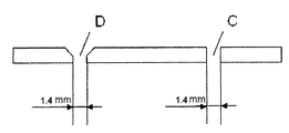
본 실시예에서 사용한 액체 스트림의 분할을 위한 장치는 분배기 구멍의 부착물 양상을 연구하기 위한 일련의 스크리닝 테스트에서의 평편한 둥근 플레이트의 형태를 취하며, 80℃ 내지 220℃의 온도에서 테스트하였다. 두께가 2 ㎜인 스테인레스 스틸 플레이트에는 2 개의 기하학적으로 상이한 구멍(유효 흐름 통과면의 등가를 확인하기 위하여 각각의 경우 직경 1.4 ㎜)이 구비되어 있다(도 6). 구멍 C 는 단순한 직선 구멍이다. 제2의 구멍 D는 모따기(45°)를 사용하여 생성되었다. 사용한 테스트 액체는 밀도가 700 내지 1,200 ㎏/㎥이고, 점도가 1 mPas 내지 100 mPas 범위내이며, 이의 표면 장력이 15 내지 50 mN/m 범위내인 중간 점도 액체이다. 액체는 용해된 성분을 포함한다. 액체에 여러 분해 반응을 실시하였으며, 이중 일부는 역학적으로는 설명되지는 않았다. 매우 미세한 결정 형태의 고체 성분(테스트 중에 형성된 현탁액) 및 고분자량의 규명되지 않은 코팅 형성 생성물 형태의 성분(부착물) 모두가 형성되었다.The apparatus for dividing the liquid stream used in this example took the form of a flat round plate in a series of screening tests to study the deposit behavior of the dispenser holes and was tested at temperatures of 80 ° C to 220 ° C.
사용한 유체는 보호 대기하에서 가열된 회로내에서 안내되며, 분배기 플레이트는 0 내지 300 ㎜의 액체 층으로 도포되었다. 플레이트를 통과하는 유체가 펌핑에 의하여 재순환되는 속도는 천공된 플레이트에서의 액체 레벨을 측정하며, 액체 레벨은 정역학 높이로 인하여 분배기 구멍을 통한 범람(run-off) 양상 또는 범람 속도를 측정한다.The used fluid was guided in a heated circuit under a protective atmosphere, and the distributor plate was applied with a liquid layer of 0 to 300 mm. The rate at which the fluid passing through the plate is recirculated by pumping measures the liquid level in the perforated plate, and the liquid level measures the run-off behavior or rate of overflow through the distributor aperture due to the static height.
테스트는 10 일간 효과적으로 지속되며, 각각의 경우에서 2 일간 쉬었다. 구멍 주위의 플레이트에서 코팅중의 크레이터 크기에 기초하여, 유체는 모따귀 처리한 구멍을 통하여 더 잘 범람하는 것(구멍 엣지에서 범람 속도가 더 높음)으로 입증될 수 있다. 스테인레스 스틸 천공된 플레이트는 매우 단단한 페이스트형 침전물로 테스트 종반에 코팅되어 고온에서조차 제거하기가 곤란하지만, 모따기 처리한 구멍은 직선 구멍에 비하여 통과 가능하였다.The test lasted effectively for 10 days, with 2 days off in each case. Based on the size of the craters in the coating at the plate around the hole, the fluid can be demonstrated to overflow better through the chamfered hole (higher overflow rate at the hole edge). Stainless steel perforated plates were coated with very hard paste-like precipitates that were difficult to remove even at high temperatures, although the chamfered holes were able to pass through straight holes.
특히, 분배기 플레이트상에서의 낮은 액체 레벨로, 상이한 기하를 갖는 2 가지 유형의 구멍을 통한 유체의 범람 양상에서 차이점이 관찰되었다. 모따기 처리 한 분배기 구멍을 통한 유체의 범람은 직선 구멍에 비하여 이로운 양상을 나타냈다. 플레이트에서의 매우 낮은 정역학 압력으로(액체 레벨이 10 내지 20 ㎜임), 모따기 처리한 구멍은 더 작은 압력 손실(더 낮은 응력 인자 및 더 낮은 압력 강하)로 인하여 출발부터 통과 가능하였다. 반대로, 직선 구멍은 유체의 등가의 범람을 관찰할 수 있도록 하기 위하여 더 높은 레벨(40 내지 50 ㎜)을 필요로 한다. 테스트에 의하면, 모따기 처리한 기하를 갖는 분배기 구멍은 날카로운 엣지를 갖는 구멍보다는 정적 작동중에 범람 양상이 더 우수한 것으로 명백히 입증되었다.In particular, with low liquid levels on the distributor plates, differences have been observed in the flood behavior of the fluid through the two types of holes with different geometries. The flooding of the fluid through the chamfered distributor hole showed a beneficial aspect compared to the straight hole. At very low static pressures in the plates (liquid levels between 10 and 20 mm), the chamfered holes were allowed to pass from the start due to smaller pressure losses (lower stress factor and lower pressure drop). In contrast, straight holes require higher levels (40-50 mm) in order to be able to observe the equivalent flooding of the fluid. Tests have clearly demonstrated that the dispenser holes with chamfered geometry have a better flooding pattern during static operation than the holes with sharp edges.
본 발명은 예시를 위하여 상기에서 구체적으로 기재하기는 하였으나, 이와 같은 구체적인 기술은 단지 예시를 위한 것일 뿐이며, 본 명세서에서는 하기의 특허청구의 범위에 의하여 한정될 수 있는 바와 같은 것을 제외하고는 본 발명의 정신 및 범위로부터 벗어남이 없이 당업자에 의하여 이루어질 수 있는 것으로 이해하여야 한다.Although the present invention has been described in detail above for the purpose of illustration, such specific techniques are for illustration only, and the present invention except as may be defined by the claims below. It should be understood that those skilled in the art can make this without departing from the spirit and scope of the invention.
도 1은 본 발명의 방법을 실시하기에 적절한 분배기 장치를 도시한다.1 shows a dispenser device suitable for practicing the method of the present invention.
도 2는 본 발명의 방법을 실시하기에 적절한 분배기 장치를 도시한다.2 shows a dispenser device suitable for practicing the method of the present invention.
도 3은 도 1에 도시한 구멍중 하나를 통한 단면을 도시한다.3 shows a cross section through one of the holes shown in FIG. 1;
도 4는 도 2에 도시한 개방부중 하나를 통한 단면을 도시한다.4 shows a section through one of the openings shown in FIG. 2.
도 5는 실시예 1로부터의 테스트 결과를 나타낸 그래프를 도시한다.5 shows a graph showing the test results from Example 1. FIG.
도 6은 다이아그램 형태로 나타낸 테스트 정렬(실시예 2)을 도시한다.6 shows a test alignment (Example 2) in diagram form.
Claims (19)
Applications Claiming Priority (2)
| Application Number | Priority Date | Filing Date | Title |
|---|---|---|---|
| DE102008039947.7 | 2008-08-27 | ||
| DE200810039947 DE102008039947A1 (en) | 2008-08-27 | 2008-08-27 | Method for dividing fluid streams |
Publications (1)
| Publication Number | Publication Date |
|---|---|
| KR20100025487A true KR20100025487A (en) | 2010-03-09 |
Family
ID=41426813
Family Applications (1)
| Application Number | Title | Priority Date | Filing Date |
|---|---|---|---|
| KR20090079256A KR20100025487A (en) | 2008-08-27 | 2009-08-26 | Method for dividing fluid streams |
Country Status (8)
| Country | Link |
|---|---|
| US (1) | US10143987B2 (en) |
| EP (1) | EP2163300B1 (en) |
| JP (1) | JP2010051959A (en) |
| KR (1) | KR20100025487A (en) |
| CN (1) | CN101658734B (en) |
| DE (1) | DE102008039947A1 (en) |
| HU (1) | HUE057853T2 (en) |
| RU (1) | RU2523482C2 (en) |
Families Citing this family (5)
| Publication number | Priority date | Publication date | Assignee | Title |
|---|---|---|---|---|
| JP5848977B2 (en) * | 2012-01-31 | 2016-01-27 | 大阪瓦斯株式会社 | Absorption refrigerator |
| CA2891002C (en) * | 2015-05-13 | 2022-09-06 | Veronica Rose Zimmerman | Modeling a bed plate and its use |
| TWI702359B (en) * | 2016-04-21 | 2020-08-21 | 富世華股份有限公司 | Tap connector with flow stabilization |
| CN110624482B (en) * | 2018-06-22 | 2022-01-07 | 万华化学集团股份有限公司 | Gas distribution plate of step-shaped fluidized bed |
| CN112361720B (en) * | 2020-10-23 | 2024-03-29 | 天富(江苏)科技有限公司 | Material drying equipment with disturbance drying function |
Family Cites Families (29)
| Publication number | Priority date | Publication date | Assignee | Title |
|---|---|---|---|---|
| DE2157736B2 (en) * | 1971-11-22 | 1978-10-05 | Schering Ag, 1000 Berlin Und 4619 Bergkamen | Device for the continuous contacting of liquids with gases or of liquids in the presence of gases or of liquids with solids in the presence of gases or of liquids with gases and finely divided solids in cocurrent |
| GB1420599A (en) * | 1972-02-02 | 1976-01-07 | Pye Ltd | Apparatus for chemical analysis including a burner |
| JPS5096648U (en) * | 1974-01-08 | 1975-08-12 | ||
| SU494193A1 (en) * | 1974-01-28 | 1975-12-05 | Distributor plate for centrifugal disc spray dryer | |
| JPS51110478A (en) * | 1975-03-26 | 1976-09-30 | Hikari Yokoegawa | Awasonyoru kiekikoryusetsushokusochi |
| DE2752391C2 (en) | 1977-11-24 | 1985-03-21 | Julius Montz Gmbh, 4010 Hilden | Distributor base |
| JPS5522351A (en) * | 1978-08-04 | 1980-02-18 | Seitetsu Kagaku Co Ltd | Tray for fluid contacting apparatus |
| JPS5916502A (en) * | 1982-07-19 | 1984-01-27 | Asahi Chem Ind Co Ltd | Perforated plate for regulating or partially collecting fluid in packed column |
| HU186652B (en) | 1982-12-23 | 1985-09-30 | Laszlo Gyoekhegyi | Plate for columns serving for distillation and/or absorption operations |
| SU1095918A1 (en) | 1983-01-18 | 1984-06-07 | Рубежанский филиал Ворошиловградского машиностроительного института | Contact device |
| DK158532C (en) | 1987-07-14 | 1990-10-29 | Niro Atomizer As | TREATMENT DEVICE WORKING WITH FLUID BED AND RENT PLATE |
| SU1690798A1 (en) * | 1989-03-22 | 1991-11-15 | Березниковское производственное объединение "Сода" им.В.И.Ленина | Mass transfer column |
| US5161315A (en) * | 1990-08-03 | 1992-11-10 | Jet-Pro Company, Inc. | Fluidized bed particulate material treating apparatus |
| US5209259A (en) * | 1991-01-15 | 1993-05-11 | E. I. Du Pont De Nemours And Company | Fluid distribution system having noise reduction mechanism |
| DE4104019C1 (en) * | 1991-02-09 | 1992-04-23 | Robert Bosch Gmbh, 7000 Stuttgart, De | |
| JPH05200201A (en) * | 1992-01-29 | 1993-08-10 | Hitachi Ltd | Gas-liquid contact device |
| JPH06328A (en) * | 1992-06-23 | 1994-01-11 | Babcock Hitachi Kk | Wet flue gas desulfurizer |
| SE502925C2 (en) | 1994-06-23 | 1996-02-19 | Abb Flaekt Ind Ab | Methods and apparatus for removing sulfur dioxide from a gas |
| EP0704232B1 (en) | 1994-09-28 | 1998-01-14 | Sulzer Chemtech AG | Liquid distributor for columns |
| JP3497029B2 (en) | 1994-12-28 | 2004-02-16 | 三井化学株式会社 | Gas dispersion plate for gas phase polymerization equipment |
| CN1144944C (en) * | 1995-03-29 | 2004-04-07 | 罗伯特·博施有限公司 | Perforated disc especially for injection valves |
| IN192183B (en) | 1995-09-07 | 2004-03-13 | Sulzer Chemtech Ag | |
| JP4491848B2 (en) | 1998-04-03 | 2010-06-30 | 東レ株式会社 | Method for producing polyamide |
| CN1134545C (en) | 1999-10-02 | 2004-01-14 | 株式会社百尼尔 | Automatic DNA purificating apparatus |
| DE10015597A1 (en) * | 2000-03-29 | 2001-12-20 | Huettlin Gmbh | Floor element for a device for treating particulate material |
| SE519545C2 (en) | 2001-07-05 | 2003-03-11 | Alstom Switzerland Ltd | Methods and apparatus for separating sulfur dioxide from a gas |
| EP1295647A1 (en) * | 2001-09-24 | 2003-03-26 | The Technology Partnership Public Limited Company | Nozzles in perforate membranes and their manufacture |
| US7883031B2 (en) * | 2003-05-20 | 2011-02-08 | James F. Collins, Jr. | Ophthalmic drug delivery system |
| RU2418628C2 (en) | 2005-12-23 | 2011-05-20 | Сименс Фаи Металз Текнолоджиз Гмбх | Distribution plate |
-
2008
- 2008-08-27 DE DE200810039947 patent/DE102008039947A1/en not_active Withdrawn
-
2009
- 2009-08-17 HU HUE09075371A patent/HUE057853T2/en unknown
- 2009-08-17 EP EP09075371.6A patent/EP2163300B1/en active Active
- 2009-08-20 US US12/544,267 patent/US10143987B2/en active Active
- 2009-08-26 KR KR20090079256A patent/KR20100025487A/en active Search and Examination
- 2009-08-26 CN CN200910171047.3A patent/CN101658734B/en active Active
- 2009-08-26 RU RU2009132109/05A patent/RU2523482C2/en not_active IP Right Cessation
- 2009-08-27 JP JP2009196203A patent/JP2010051959A/en active Pending
Also Published As
| Publication number | Publication date |
|---|---|
| DE102008039947A1 (en) | 2010-03-04 |
| JP2010051959A (en) | 2010-03-11 |
| RU2523482C2 (en) | 2014-07-20 |
| CN101658734B (en) | 2017-03-01 |
| US20100071770A1 (en) | 2010-03-25 |
| EP2163300A1 (en) | 2010-03-17 |
| CN101658734A (en) | 2010-03-03 |
| HUE057853T2 (en) | 2022-06-28 |
| EP2163300B1 (en) | 2021-12-22 |
| RU2009132109A (en) | 2011-03-10 |
| US10143987B2 (en) | 2018-12-04 |
Similar Documents
| Publication | Publication Date | Title |
|---|---|---|
| KR20100025487A (en) | Method for dividing fluid streams | |
| Mansouri et al. | Experimental and numerical investigation of the effect of viscosity and particle size on the erosion damage caused by solid particles | |
| JP4913058B2 (en) | Multi-fluid injection mixer | |
| US7803323B2 (en) | System and method for cleaning in-process sensors | |
| WO1999047897A1 (en) | Multi-phase fluid flow measurement apparatus and method | |
| Jiang et al. | Mixing behavior of 45 inclined dense jets in currents | |
| JP6819415B2 (en) | Reaction tank and stirring reactor | |
| Chailad et al. | Development of slurry-jet erosion test for elastomeric materials | |
| Hojo et al. | Erosion damage of polymeric material by slurry | |
| Hu et al. | Experimental investigation on submerged gas-liquid mixture injection into water through a micro-channel | |
| Sapre et al. | Investigation into the evolution of corrosion product layer (CPL) of 1018 C-steel exposed to multiphase environment using FIB and EIS techniques | |
| JP7357744B1 (en) | cleaning ring | |
| JP7361861B1 (en) | Cleaning ring and reaction device | |
| US20150136708A1 (en) | Dissolved gas flotation apparatus | |
| Bagatur | Experimental analysis of flow characteristics from different circular nozzles at plunging water jets | |
| RU2141105C1 (en) | Device for taking liquid samples from pipeline | |
| Yang et al. | In-situ electrochemical testing and fluid dynamics simulation of pipeline defects under flow accelerated corrosion | |
| Wang et al. | Direct observation of single-and two-phase flows in spacer filled membrane modules | |
| CN111473916B (en) | Monitoring method for crystallizer corrosion leakage condition | |
| Quddus et al. | Influence of solution hydrodynamics on the deposition of CaSO4 scale on aluminum | |
| JP2005138132A (en) | Continuous casting method for steel | |
| Barreto et al. | Effect of surfactant (foamer) delivery location on horizontal wells deliquification | |
| DA SILVA | Corrosion in multiphase-flow pipelines: the impact on the oil and gas industry | |
| Wang et al. | Mass-transfer enhancement in large-diameter pipeline under water/gas stationary slug flow | |
| RU2309006C1 (en) | Device for treatment of the fluid medium |
Legal Events
| Date | Code | Title | Description |
|---|---|---|---|
| A201 | Request for examination | ||
| E902 | Notification of reason for refusal | ||
| AMND | Amendment | ||
| E902 | Notification of reason for refusal | ||
| AMND | Amendment | ||
| E601 | Decision to refuse application | ||
| AMND | Amendment |