KR20090113751A - Image display device - Google Patents
Image display device Download PDFInfo
- Publication number
- KR20090113751A KR20090113751A KR20087024843A KR20087024843A KR20090113751A KR 20090113751 A KR20090113751 A KR 20090113751A KR 20087024843 A KR20087024843 A KR 20087024843A KR 20087024843 A KR20087024843 A KR 20087024843A KR 20090113751 A KR20090113751 A KR 20090113751A
- Authority
- KR
- South Korea
- Prior art keywords
- pixel
- unit
- frame
- video signal
- value
- Prior art date
Links
Images


Classifications
-
- H—ELECTRICITY
- H04—ELECTRIC COMMUNICATION TECHNIQUE
- H04N—PICTORIAL COMMUNICATION, e.g. TELEVISION
- H04N7/00—Television systems
- H04N7/01—Conversion of standards, e.g. involving analogue television standards or digital television standards processed at pixel level
- H04N7/0127—Conversion of standards, e.g. involving analogue television standards or digital television standards processed at pixel level by changing the field or frame frequency of the incoming video signal, e.g. frame rate converter
- H04N7/0132—Conversion of standards, e.g. involving analogue television standards or digital television standards processed at pixel level by changing the field or frame frequency of the incoming video signal, e.g. frame rate converter the field or frame frequency of the incoming video signal being multiplied by a positive integer, e.g. for flicker reduction
-
- G—PHYSICS
- G09—EDUCATION; CRYPTOGRAPHY; DISPLAY; ADVERTISING; SEALS
- G09G—ARRANGEMENTS OR CIRCUITS FOR CONTROL OF INDICATING DEVICES USING STATIC MEANS TO PRESENT VARIABLE INFORMATION
- G09G3/00—Control arrangements or circuits, of interest only in connection with visual indicators other than cathode-ray tubes
- G09G3/20—Control arrangements or circuits, of interest only in connection with visual indicators other than cathode-ray tubes for presentation of an assembly of a number of characters, e.g. a page, by composing the assembly by combination of individual elements arranged in a matrix no fixed position being assigned to or needed to be assigned to the individual characters or partial characters
- G09G3/34—Control arrangements or circuits, of interest only in connection with visual indicators other than cathode-ray tubes for presentation of an assembly of a number of characters, e.g. a page, by composing the assembly by combination of individual elements arranged in a matrix no fixed position being assigned to or needed to be assigned to the individual characters or partial characters by control of light from an independent source
- G09G3/36—Control arrangements or circuits, of interest only in connection with visual indicators other than cathode-ray tubes for presentation of an assembly of a number of characters, e.g. a page, by composing the assembly by combination of individual elements arranged in a matrix no fixed position being assigned to or needed to be assigned to the individual characters or partial characters by control of light from an independent source using liquid crystals
-
- G—PHYSICS
- G09—EDUCATION; CRYPTOGRAPHY; DISPLAY; ADVERTISING; SEALS
- G09G—ARRANGEMENTS OR CIRCUITS FOR CONTROL OF INDICATING DEVICES USING STATIC MEANS TO PRESENT VARIABLE INFORMATION
- G09G3/00—Control arrangements or circuits, of interest only in connection with visual indicators other than cathode-ray tubes
- G09G3/20—Control arrangements or circuits, of interest only in connection with visual indicators other than cathode-ray tubes for presentation of an assembly of a number of characters, e.g. a page, by composing the assembly by combination of individual elements arranged in a matrix no fixed position being assigned to or needed to be assigned to the individual characters or partial characters
- G09G3/34—Control arrangements or circuits, of interest only in connection with visual indicators other than cathode-ray tubes for presentation of an assembly of a number of characters, e.g. a page, by composing the assembly by combination of individual elements arranged in a matrix no fixed position being assigned to or needed to be assigned to the individual characters or partial characters by control of light from an independent source
- G09G3/3406—Control of illumination source
-
- G—PHYSICS
- G09—EDUCATION; CRYPTOGRAPHY; DISPLAY; ADVERTISING; SEALS
- G09G—ARRANGEMENTS OR CIRCUITS FOR CONTROL OF INDICATING DEVICES USING STATIC MEANS TO PRESENT VARIABLE INFORMATION
- G09G3/00—Control arrangements or circuits, of interest only in connection with visual indicators other than cathode-ray tubes
- G09G3/20—Control arrangements or circuits, of interest only in connection with visual indicators other than cathode-ray tubes for presentation of an assembly of a number of characters, e.g. a page, by composing the assembly by combination of individual elements arranged in a matrix no fixed position being assigned to or needed to be assigned to the individual characters or partial characters
- G09G3/34—Control arrangements or circuits, of interest only in connection with visual indicators other than cathode-ray tubes for presentation of an assembly of a number of characters, e.g. a page, by composing the assembly by combination of individual elements arranged in a matrix no fixed position being assigned to or needed to be assigned to the individual characters or partial characters by control of light from an independent source
- G09G3/36—Control arrangements or circuits, of interest only in connection with visual indicators other than cathode-ray tubes for presentation of an assembly of a number of characters, e.g. a page, by composing the assembly by combination of individual elements arranged in a matrix no fixed position being assigned to or needed to be assigned to the individual characters or partial characters by control of light from an independent source using liquid crystals
- G09G3/3611—Control of matrices with row and column drivers
- G09G3/3648—Control of matrices with row and column drivers using an active matrix
-
- H—ELECTRICITY
- H04—ELECTRIC COMMUNICATION TECHNIQUE
- H04N—PICTORIAL COMMUNICATION, e.g. TELEVISION
- H04N5/00—Details of television systems
- H04N5/14—Picture signal circuitry for video frequency region
- H04N5/144—Movement detection
- H04N5/145—Movement estimation
-
- H—ELECTRICITY
- H04—ELECTRIC COMMUNICATION TECHNIQUE
- H04N—PICTORIAL COMMUNICATION, e.g. TELEVISION
- H04N5/00—Details of television systems
- H04N5/14—Picture signal circuitry for video frequency region
- H04N5/20—Circuitry for controlling amplitude response
- H04N5/205—Circuitry for controlling amplitude response for correcting amplitude versus frequency characteristic
- H04N5/208—Circuitry for controlling amplitude response for correcting amplitude versus frequency characteristic for compensating for attenuation of high frequency components, e.g. crispening, aperture distortion correction
-
- H—ELECTRICITY
- H04—ELECTRIC COMMUNICATION TECHNIQUE
- H04N—PICTORIAL COMMUNICATION, e.g. TELEVISION
- H04N5/00—Details of television systems
- H04N5/66—Transforming electric information into light information
-
- G—PHYSICS
- G09—EDUCATION; CRYPTOGRAPHY; DISPLAY; ADVERTISING; SEALS
- G09G—ARRANGEMENTS OR CIRCUITS FOR CONTROL OF INDICATING DEVICES USING STATIC MEANS TO PRESENT VARIABLE INFORMATION
- G09G2310/00—Command of the display device
- G09G2310/02—Addressing, scanning or driving the display screen or processing steps related thereto
- G09G2310/024—Scrolling of light from the illumination source over the display in combination with the scanning of the display screen
-
- G—PHYSICS
- G09—EDUCATION; CRYPTOGRAPHY; DISPLAY; ADVERTISING; SEALS
- G09G—ARRANGEMENTS OR CIRCUITS FOR CONTROL OF INDICATING DEVICES USING STATIC MEANS TO PRESENT VARIABLE INFORMATION
- G09G2310/00—Command of the display device
- G09G2310/06—Details of flat display driving waveforms
- G09G2310/061—Details of flat display driving waveforms for resetting or blanking
-
- G—PHYSICS
- G09—EDUCATION; CRYPTOGRAPHY; DISPLAY; ADVERTISING; SEALS
- G09G—ARRANGEMENTS OR CIRCUITS FOR CONTROL OF INDICATING DEVICES USING STATIC MEANS TO PRESENT VARIABLE INFORMATION
- G09G2320/00—Control of display operating conditions
- G09G2320/02—Improving the quality of display appearance
- G09G2320/0261—Improving the quality of display appearance in the context of movement of objects on the screen or movement of the observer relative to the screen
-
- G—PHYSICS
- G09—EDUCATION; CRYPTOGRAPHY; DISPLAY; ADVERTISING; SEALS
- G09G—ARRANGEMENTS OR CIRCUITS FOR CONTROL OF INDICATING DEVICES USING STATIC MEANS TO PRESENT VARIABLE INFORMATION
- G09G2320/00—Control of display operating conditions
- G09G2320/06—Adjustment of display parameters
- G09G2320/0606—Manual adjustment
-
- G—PHYSICS
- G09—EDUCATION; CRYPTOGRAPHY; DISPLAY; ADVERTISING; SEALS
- G09G—ARRANGEMENTS OR CIRCUITS FOR CONTROL OF INDICATING DEVICES USING STATIC MEANS TO PRESENT VARIABLE INFORMATION
- G09G2320/00—Control of display operating conditions
- G09G2320/06—Adjustment of display parameters
- G09G2320/0613—The adjustment depending on the type of the information to be displayed
- G09G2320/062—Adjustment of illumination source parameters
-
- G—PHYSICS
- G09—EDUCATION; CRYPTOGRAPHY; DISPLAY; ADVERTISING; SEALS
- G09G—ARRANGEMENTS OR CIRCUITS FOR CONTROL OF INDICATING DEVICES USING STATIC MEANS TO PRESENT VARIABLE INFORMATION
- G09G2320/00—Control of display operating conditions
- G09G2320/06—Adjustment of display parameters
- G09G2320/0626—Adjustment of display parameters for control of overall brightness
-
- G—PHYSICS
- G09—EDUCATION; CRYPTOGRAPHY; DISPLAY; ADVERTISING; SEALS
- G09G—ARRANGEMENTS OR CIRCUITS FOR CONTROL OF INDICATING DEVICES USING STATIC MEANS TO PRESENT VARIABLE INFORMATION
- G09G2320/00—Control of display operating conditions
- G09G2320/10—Special adaptations of display systems for operation with variable images
- G09G2320/106—Determination of movement vectors or equivalent parameters within the image
-
- G—PHYSICS
- G09—EDUCATION; CRYPTOGRAPHY; DISPLAY; ADVERTISING; SEALS
- G09G—ARRANGEMENTS OR CIRCUITS FOR CONTROL OF INDICATING DEVICES USING STATIC MEANS TO PRESENT VARIABLE INFORMATION
- G09G2340/00—Aspects of display data processing
- G09G2340/04—Changes in size, position or resolution of an image
- G09G2340/0407—Resolution change, inclusive of the use of different resolutions for different screen areas
- G09G2340/0435—Change or adaptation of the frame rate of the video stream
-
- G—PHYSICS
- G09—EDUCATION; CRYPTOGRAPHY; DISPLAY; ADVERTISING; SEALS
- G09G—ARRANGEMENTS OR CIRCUITS FOR CONTROL OF INDICATING DEVICES USING STATIC MEANS TO PRESENT VARIABLE INFORMATION
- G09G2360/00—Aspects of the architecture of display systems
- G09G2360/14—Detecting light within display terminals, e.g. using a single or a plurality of photosensors
- G09G2360/144—Detecting light within display terminals, e.g. using a single or a plurality of photosensors the light being ambient light
-
- G—PHYSICS
- G09—EDUCATION; CRYPTOGRAPHY; DISPLAY; ADVERTISING; SEALS
- G09G—ARRANGEMENTS OR CIRCUITS FOR CONTROL OF INDICATING DEVICES USING STATIC MEANS TO PRESENT VARIABLE INFORMATION
- G09G2360/00—Aspects of the architecture of display systems
- G09G2360/16—Calculation or use of calculated indices related to luminance levels in display data
-
- H—ELECTRICITY
- H04—ELECTRIC COMMUNICATION TECHNIQUE
- H04N—PICTORIAL COMMUNICATION, e.g. TELEVISION
- H04N7/00—Television systems
- H04N7/01—Conversion of standards, e.g. involving analogue television standards or digital television standards processed at pixel level
- H04N7/0112—Conversion of standards, e.g. involving analogue television standards or digital television standards processed at pixel level one of the standards corresponding to a cinematograph film standard
-
- H—ELECTRICITY
- H04—ELECTRIC COMMUNICATION TECHNIQUE
- H04N—PICTORIAL COMMUNICATION, e.g. TELEVISION
- H04N7/00—Television systems
- H04N7/01—Conversion of standards, e.g. involving analogue television standards or digital television standards processed at pixel level
- H04N7/0117—Conversion of standards, e.g. involving analogue television standards or digital television standards processed at pixel level involving conversion of the spatial resolution of the incoming video signal
- H04N7/012—Conversion between an interlaced and a progressive signal
Abstract
Description
본 발명은, 소정의 영상 신호 처리를 행하는 영상 신호 처리 장치를 구비한The present invention provides a video signal processing apparatus that performs a predetermined video signal processing.
홀드형의 화상 표시 장치에 관한 것이다.A hold type image display apparatus is provided.
텔레비전 수신기나 DVD 플레이어 등에 있어서 화질 향상을 위한 영상 신호 처리의 하나로, 움직임 보상을 이용한 프레임 레이트 변환이 존재한다.As one of video signal processing for improving image quality in a television receiver, a DVD player, or the like, there is a frame rate conversion using motion compensation.
이 프레임 레이트 변환의 원리를, 텔레비전 방송용의 카메라로 촬영된 영상 신호(이하, 카메라 신호라고 칭함)와, 필름으로부터 텔레비전 방식으로 텔레시네 변환된 영상 신호(이하, 필름 신호 또는 시네마 신호라고 칭함)에 관해, 도 1 내지 도 3을 이용하여 설명한다.The principle of the frame rate conversion is a video signal photographed by a camera for television broadcasting (hereinafter referred to as a camera signal) and a video signal telecine-converted from film to a television method (hereinafter referred to as a film signal or a cinema signal). 1 to 3 will be described.
도 1(a)는, NTSC 방식의 카메라 신호의 오리지널의 프레임(A, B, C, D)을 도시하고 있다. 이 카메라 신호의 프레임 레이트를 120Hz로 변환하는 경우에는, 도 1(b)에 도시하는 바와 같이, 이웃하는 오리지널 프레임(프레임(A)과 프레임(B)이나, 프레임(B)과 프레임(C)이나, 프레임(C)과 프레임(D)) 사이에, 1/120sec의 타이밍에서 하나씩 보간 프레임이 추가된다.Fig. 1 (a) shows original frames A, B, C, and D of the NTSC camera signal. When converting the frame rate of this camera signal to 120 Hz, as shown in FIG. 1 (b), neighboring original frames (frame A and frame B, or frame B and frame C) Alternatively, between the frames C and D, interpolation frames are added one by one at a timing of 1/120 sec.
도 2(a)는, PAL 방식으로 텔레시네 변환(2:2 풀다운)된 필름 신호의 오리지널의 프레임(A, B, C, D)을 도시하고 있다. 각 오리지널 프레임은 2회씩 반복되고 있다. 이 2:2 풀다운 필름 신호의 프레임 레이트를 100Hz로 변환하는 경우에는, 도 2(b)에 도시하는 바와 같이, 25Hz 주기로 이웃하는 오리지널 프레임(프레임(A)과 프레임(B)이나, 프레임(B)과 프레임(C)이나, 프레임(C)과 프레임(D)) 사이에, 1/100sec 간격으로 3개씩 보간 프레임이 추가된다.FIG. 2 (a) shows the original frames A, B, C, and D of the film signal telecine converted (2: 2 pull down) by the PAL method. Each original frame is repeated twice. When converting the frame rate of this 2: 2 pull-down film signal to 100 Hz, as shown in FIG.2 (b), the original frame (frame A, frame B, or frame B) which adjoins by 25 Hz period is shown. ) And frame (C) or interpolation frames are added three times at intervals of 1/100 sec between frames (C) and (D).
도 3(a)는, NTSC 방식으로 텔레시네 변환(3:2 풀다운)된 필름 신호의 오리지널의 프레임(A, B, C)을 도시하고 있다. 홀수번째의 오리지널 프레임(A, C)은 3회 반복되고, 짝수번째의 오리지널 프레임(B)은 2회 반복되고 있다. 이 3:2 풀다운 필름 신호의 프레임 레이트를 120Hz로 변환하는 경우에는, 도 3(b)에 도시하는 바와 같이, 24Hz 주기로 이웃하는 오리지널 프레임(프레임(A)과 프레임(B)이나, 프레임(B)h 프레임(C)) 사이에, 1/120sec 간격으로 4개씩 보간 프레임이 추가된다.Fig. 3A shows the original frames A, B, and C of the film signal telecine converted (3: 2 pull down) in the NTSC system. The odd original frames A and C are repeated three times, and the even original frames B are repeated twice. When converting the frame rate of this 3: 2 pull-down film signal to 120Hz, as shown in FIG.3 (b), the original frame (frame A, frame B, or frame B) which adjoins every 24 Hz period is shown. Between the h frames C), four interpolation frames are added at intervals of 1/120 sec.
각 보간 프레임은, 전후의 오리지널 프레임의 영상을 보간함에 의해 작성된다. 이 보간은, 각 보간 프레임에서의 영상의 보간 위치의 파라미터와, 전후의 오리지널 프레임 사이의 움직임 벡터에 의거하여, 보간 프레임의 화소치를 계산하기 위해 이용하는 전후의 오리지널 프레임의 화소의 어드레스를 계산한 후, 그들의 어드레스의 화소치를, 보간 위치에 따라 무게 부여한다는 방법으로 행하여진다.Each interpolation frame is created by interpolating the video of the original frame before and after. The interpolation is performed based on the parameters of the interpolation position of the video in each interpolation frame and the motion vector between the preceding and following original frames, and after calculating the address of the pixels of the original frame before and after which are used to calculate the pixel values of the interpolation frame. The pixel values of these addresses are weighted in accordance with the interpolation position.
이러한 프레임 레이트 변환에는, 카메라 신호에 있어서의 움직임 흐림을 해소하는 효과나, 필름 신호에 있어서의 저더(judder)(영상의 움직임의 흔들림)를 삭감하는 효과가 있다.Such frame rate conversion has an effect of eliminating motion blur in a camera signal, and an effect of reducing judder (shake of the motion of a video) in a film signal.
도 1 내지 도 3에는, 종래의 프레임 레이트 변환에 있어서의, 각 보간 프레임에서의 영상의 보간 위치도 도시하고 있다. 도 1(b)에 도시하는 바와 같이, NTSC 방식의 카메라 신호의 프레임 레이트를 120Hz로 변환할 때의 보간 프레임에서의 영상의 보간 위치는, 종래, 전후의 오리지널 프레임 사이의 영상의 움직임의 크기(움직임 벡터 검출에 의해 구한 크기)를 균등하게 2분할 한 위치, 즉 이 움직임의 크기에 대해 50%의 위치로 되어 있다.1 to 3 also show interpolation positions of the video in each interpolation frame in the conventional frame rate conversion. As shown in Fig. 1 (b), the interpolation position of the video in the interpolation frame when converting the frame rate of the NTSC camera signal to 120 Hz is conventionally the magnitude of the motion of the video between the original frames before and after ( The size obtained by the motion vector detection is equally divided into two, that is, the position of 50% of the size of the motion.
도 2(b)에 도시하는 바와 같이, 2:2 풀다운 필름 신호의 프레임 레이트를 100Hz로 변환할 때의 3개의 보간 프레임에서의 영상의 보간 위치는, 종래, 전후의 오리지널 프레임 사이의 영상의 움직임의 크기를 균등하게 4분할한 위치, 즉 이 움직임의 크기에 대해 각각 25%, 50%, 75%의 위치로 되어 있다.As shown in Fig. 2 (b), the interpolation positions of the images in the three interpolation frames when the frame rate of the 2: 2 pulldown film signal is converted to 100 Hz are conventionally the movements of the images between the original frames before and after. The size of is equally divided into four, that is, 25%, 50% and 75% of the size of the movement, respectively.
도 3(b)에 도시하는 바와 같이, 3:2 풀다운 필름 신호의 프레임 레이트를 120Hz로 변환할 때의 4개의 보간 프레임에서의 영상의 보간 위치는, 종래, 전후의 오리지널 프레임 사이의 영상의 움직임의 크기를 균등하게 5분할한 위치, 즉 이 움직임의 크기에 대해 각각 20%, 40%, 60%, 80%의 위치로 되어 있다.As shown in Fig. 3B, the interpolation positions of the images in four interpolation frames when the frame rate of the 3: 2 pull-down film signal is converted to 120 Hz are conventionally the movements of the images between the original frames before and after. The size of is equally divided into five positions, that is, the positions of 20%, 40%, 60%, and 80%, respectively, for the size of this movement.
도 4는, 종래의 보간 위치에서 프레임 레이트 변환한 3:2 풀다운 필름 신호의 영상을 예시하는 도면이다. 이웃하는 오리지널 프레임(A와 B) 사이에서 비행기의 영상이 움직이고 있고, 4개의 보간 프레임에서, 이 움직임의 크기를 균등하게 5분할한 위치에 비행기의 영상이 보간되어 있다.4 is a diagram illustrating an image of a 3: 2 pulldown film signal that is frame rate converted at a conventional interpolation position. The video of the plane is moving between neighboring original frames A and B, and the video of the plane is interpolated at positions where the magnitude of this movement is equally divided into five interpolation frames.
또한, 이와 같은 프레임 레이트 변환에 관한 기술로서는, 예를 들면 특허 문헌 1에서 제안된 것을 들 수 있다.Moreover, as a technique regarding such frame rate conversion, the thing proposed by patent document 1 is mentioned, for example.
특허 문헌 1 : 일본 특개2003-189257호 공보Patent Document 1: Japanese Patent Application Laid-Open No. 2003-189257
상기한 바와 같이, 움직임 보상을 이용한 프레임 레이트 변환에서는, 종래, 각 보간 프레임에서의 영상의 보간 위치를, 전후의 오리지널 프레임 사이에서의 영상의 움직임의 크기를 균등하게 분할한 위치로 설정하고 있다.As described above, in frame rate conversion using motion compensation, the interpolation position of an image in each interpolation frame is conventionally set to a position where the magnitude of the motion of the image between the original frames before and after is equally divided.
그런데, 필름 신호인 경우에, 도 4에 예시한 바와 같이 오리지널 프레임 사이의 영상의 움직임의 크기를 균등하게 분할한 보간 위치에서 보간을 행하면, 저더가 대폭적으로 삭감되어 영상의 움직임이 매우 스무스(smooth)하게 된다. 그 결과, 필름 신호의 저더에 익숙해져 있는 사람에게 있어서는, 오히려 필름 신호인 것 같지 않다는 인상을 받게 되어 버리는 일이 있다.By the way, in the case of a film signal, as shown in Fig. 4, when interpolation is performed at an interpolation position in which the magnitude of the motion of the image between the original frames is equally divided, judder is greatly reduced and the motion of the image is very smooth. ) As a result, in the person who is used to the judging of a film signal, the impression that it does not seem to be a film signal may be rather received.
또한, 움직임 보상을 이용한 프레임 레이트 변환에서는, 이웃하는 오리지널 프레임 사이의 영상의 움직임이 매우 빨라진 경우, 움직임 벡터의 탐색 범위(블록 매칭을 행하는 범위)를 초과하여 버리기 때문에, 큰 저더가 발생한다. 그러한 경우, 움직임이 매우 스무스한 영상을 보고 있는 도중에 돌연 큰 저더가 발생하기 때문에, 위화감을 느껴 버린다는 문제가 있다.Further, in frame rate conversion using motion compensation, when the motion of an image between neighboring original frames becomes very fast, a large judder is generated because the motion range of the motion vector (the range for block matching) is exceeded. In such a case, there is a problem in that a large judder occurs suddenly while viewing a very smooth image of motion, and thus a feeling of discomfort is felt.
또한, 종래, 필름 신호(시네마 신호)를 프레임 레이트 변환할 때의 영상의 움직임을 보다 스무스하게 하기 위해, 프레임 레이트 변환 후의 필드의 화소 위치를 움직임 벡터의 방향으로 시프트시키는 기술은 제안되어 있다(특허 문헌 1 참조). 그러나, 필름 신호를 프레임 레이트 변환한 때에, 저더를 삭감하면서, 그 삭감의 정도를 약하게 하기 위한 기술은 제안되어 있지 않다.Moreover, in order to make the motion of the image at the time of frame rate conversion of a film signal (cinema signal) smoother more, the technique which shifts the pixel position of the field after frame rate conversion to the direction of a motion vector is proposed (patented). See Document 1). However, when the film signal is frame rate converted, a technique for reducing the degree of the reduction while reducing the judder has not been proposed.
그런데, 이와 같이 프레임 레이트 변환 등의 화질 개선용의 영상 신호 처리를 움직임 벡터를 이용하여 행하는 경우에 있어서, 상기한 바와 같이 움직임 벡터의 탐색 범위(블록 매칭을 행하는 범위)를 초과하여 버린 때 등은, 움직임 벡터의 검출이 능숙하게 될 수 없는 경우가 있다. 이와 같은 경우, 그 움직임 벡터를 그대로 이용하면, 영상 신호 처리도 능숙하게 되지 않고, 오히려 화질 열화가 생겨 버리는 경우가 있다는 다른 문제도 있다.By the way, when the video signal processing for image quality improvement such as frame rate conversion is performed using the motion vector, when the search range of the motion vector (the range for block matching) is exceeded as described above, In some cases, the detection of the motion vector may be difficult. In such a case, if the motion vector is used as it is, there is another problem that video signal processing is not proficient, but image quality deterioration may occur.
또한, 이와 같이 영상 신호 처리가 이루어진 후의 영상 신호를, 액정 표시 장치 등의 고정 화소(홀드)형의 표시 장치에 표시한 경우, 그 구조에 기인하여 이른바 홀드 흐림이 생겨 버린다는 또 다른 문제도 있고, 이 홀드 흐림을 가능한 한 개선하는 것이 요망되고 있다. 단, 이와 같은 홀드 흐림은, 상황에 따라 보기 편함이 변화하기 때문에, 상황에 따른 개선방법이 바람직하다.In addition, when the video signal after the video signal processing is performed on a fixed pixel (hold) type display device such as a liquid crystal display device, there is another problem that a so-called hold blur occurs due to its structure. It is desired to improve the hold blur as much as possible. However, such hold blur is easy to see depending on the situation, and therefore, an improvement method according to the situation is preferable.
본 발명은 이러한 문제점을 감안하여 이루어진 것으로, 그 제 1의 목적은, 움직임 보상을 이용하여 필름 신호(시네마 신호)의 프레임 레이트 변환을 행한 때에, 저더를 삭감하면서, 그 삭감의 정도를 약하게 하는 것이 가능한 화상 표시 장치, 영상 신호 처리 장치 및 영상 신호 처리 방법을 제공하는 데 있다.This invention is made | formed in view of such a problem, The 1st objective is to weaken the grade of the reduction, reducing judder when frame rate conversion of a film signal (cinema signal) using motion compensation. It is possible to provide a possible image display apparatus, an image signal processing apparatus, and an image signal processing method.
또한, 본 발명의 제 2의 목적은, 소정의 화질 개선용의 영상 신호 처리를 행할 때에, 움직임 벡터의 검출 정밀도에 기인한 화질 열화를 억제하는 것이 가능한 화상 표시 장치, 영상 신호 처리 장치 및 영상 신호 처리 방법을 제공하는 데 있다.Further, a second object of the present invention is an image display device, a video signal processing device, and a video signal capable of suppressing image quality deterioration due to the detection accuracy of a motion vector when performing video signal processing for predetermined image quality improvement. To provide a treatment method.
또한, 본 발명의 제 3의 목적은, 상황에 따라 홀드 흐림을 개선시키는 것이 가능한 화상 표시 장치를 제공하는 데 있다.Further, a third object of the present invention is to provide an image display device capable of improving hold blur depending on a situation.
본 발명의 화상 표시 장치는, 시간축에 따른 복수의 오리지널의 프레임에 대해, 소정의 영상 신호 처리를 행하는 영상 신호 처리 수단과, 이와 같은 영상 신호 처리가 이루어진 후의 영상 신호에 의거하여 영상 표시를 행하는 표시 수단을 구비한 것이다. 여기서, 이 표시 수단은, 홀드형의 표시 수단이다. 또한, 상기 오리지널의 프레임에서의 영상 신호의 내용 및 유저의 시청 환경의 밝기의 적어도 한쪽에 따라, 표시 수단에 있어서의 표시 화면상에 흑표시 영역이 삽입되는 흑삽입 처리가 이루어지도록 구성되어 있다.The image display device of the present invention is a display that performs video display based on video signal processing means for performing predetermined video signal processing on a plurality of original frames along the time axis, and video signals after such video signal processing has been performed. It is equipped with a means. Here, this display means is a hold-type display means. Further, the black insertion process is performed such that a black display region is inserted on the display screen of the display means in accordance with at least one of the contents of the video signal in the original frame and the brightness of the user's viewing environment.
본 발명의 화상 표시 장치에서는, 시간축에 따른 복수의 오리지널의 프레임에 대해, 소정의 영상 신호 처리가 이루어지고, 이와 같은 영상 신호 처리가 이루어진 후의 영상 신호에 의거하여, 영상 표시가 행하여진다. 또한, 오리지널의 프레임에서의 영상 신호의 내용 및 유저의 시청 환경의 밝기의 적어도 한쪽에 따라, 표시 수단에 있어서의 표시 화면상에 흑표시 영역이 삽입되는 흑삽입 처리가 이루어진다.In the image display device of the present invention, predetermined video signal processing is performed on a plurality of original frames along the time axis, and video display is performed based on the video signal after such video signal processing is performed. Further, black insertion processing is performed in which a black display region is inserted on the display screen of the display means in accordance with at least one of the contents of the video signal in the original frame and the brightness of the user's viewing environment.
본 발명의 화상 표시 장치에 의하면, 오리지널의 프레임에서의 영상 신호의 내용 및 유저의 시청 환경의 밝기의 적어도 한쪽에 따라, 표시 수단에 있어서의 표시 화면상에 흑표시 영역이 삽입되는 흑삽입 처리가 이루어지도록 하였기 때문에, 상황에 따라 홀드 흐림을 개선 시키는 것이 가능하게 된다.According to the image display device of the present invention, black insertion processing is performed in which a black display area is inserted on a display screen of the display means in accordance with at least one of the contents of the video signal in the original frame and the brightness of the viewing environment of the user. Because it is made, it is possible to improve the hold blur depending on the situation.
도 1은 카메라 신호의 프레임 레이트 변환의 원리 및 종래의 보간 위치를 도시하는 도면.1 shows the principle of frame rate conversion of a camera signal and a conventional interpolation position.
도 2는 필름 신호의 프레임 레이트 변환의 원리 및 종래의 보간 위치를 도시하는 도면.2 shows the principle of frame rate conversion of a film signal and a conventional interpolation position.
도 3은 필름 신호의 프레임 레이트 변환의 원리 및 종래의 보간 위치를 도시하는 도면.3 illustrates the principle of frame rate conversion of film signals and conventional interpolation positions.
도 4는 종래의 보간 위치에서 프레임 레이트 변환을 행한 필름 신호의 영상을 예시하는 도면.4 is a diagram illustrating an image of a film signal subjected to frame rate conversion at a conventional interpolation position.
도 5는 본 발명의 제 1의 실시의 형태에 관한 영상 신호 처리 장치의 회로 구성예를 도시하는 블록도.Fig. 5 is a block diagram showing a circuit configuration example of a video signal processing device according to the first embodiment of the present invention.
도 6은 인터폴레이터(interpolate)에서의 어드레스 계산의 원리를 도시하는 도면.6 illustrates the principle of address calculation in an interpolate.
도 7은 CPU가 공급하는 보간 위치 파라미터를 도시하는 도면.7 is a diagram illustrating interpolation position parameters supplied by a CPU.
도 8은 3:2 풀다운 필름 신호인 경우의 보간 위치 파라미터의 값을 도시하는 도면.FIG. 8 is a diagram showing a value of an interpolation position parameter in the case of a 3: 2 pulldown film signal. FIG.
도 9는 2:2 풀다운 필름 신호인 경우의 보간 위치 파라미터의 값을 도시하는 도면.9 is a diagram showing a value of an interpolation position parameter in the case of a 2: 2 pulldown film signal.
도 10은 도 5의 장치에서 프레임 레이트 변환을 행한 필름 신호의 영상을 예시하는 도면.FIG. 10 is a diagram illustrating an image of a film signal subjected to frame rate conversion in the apparatus of FIG. 5. FIG.
도 11은 제 1의 실시의 형태의 변형예에 관한 영상 신호 처리 장치의 회로 구성예를 도시하는 블록도.FIG. 11 is a block diagram showing a circuit configuration example of a video signal processing apparatus according to a modification of the first embodiment. FIG.
도 12는 카메라 신호의 240Hz로의 프레임 레이트 변환을 도시하는 도면.12 illustrates frame rate conversion of a camera signal to 240 Hz.
도 13은 본 발명의 제 2의 실시의 형태에 관한 영상 신호 처리 장치의 구성의 한 예를 도시하는 블록도.FIG. 13 is a block diagram showing an example of a configuration of a video signal processing apparatus according to a second embodiment of the present invention. FIG.
도 14는 인간의 망막상에서 형성된 상의 흐림의 주파수 특성의 한 예를 도시하는 도면.FIG. 14 shows an example of the frequency characteristics of blur of a phase formed on a human retina. FIG.
도 15는 도 13의 영상 신호 처리 장치가 실행하는 화상 처리의 한 예를 설명하는 플로우 차트.FIG. 15 is a flowchart for explaining an example of image processing executed by the video signal processing apparatus of FIG. 13; FIG.
도 16은 이동 벡터(이동 속도, 움직임 벡터)에 따른 촬상 흐림의 주파수 특성의 한 예를 도시하는 도면.Fig. 16 is a diagram showing an example of frequency characteristics of imaging blur according to a motion vector (moving speed, motion vector).
도 17은 도 13의 영상 신호 처리 장치중의 촬상 흐림 억제 처리부의 기능적 구성의 한 예를 도시하는 블록도.FIG. 17 is a block diagram illustrating an example of a functional configuration of an imaging blur suppression processor in the video signal processing device of FIG. 13. FIG.
도 18은 도 17의 촬상 흐림 억제 처리부 중의 고역 성분 제거부의 기능적 구성의 한 예를 도시하는 블록도.FIG. 18 is a block diagram showing an example of a functional configuration of a high frequency component removing unit in the imaging blur suppression processor of FIG. 17; FIG.
도 19는 도 18의 고역 성분 제거부 중의 고역 리미터부의 특성의 한 예를 도시하는 도면.FIG. 19 is a diagram illustrating an example of the characteristics of the high frequency limiter portion in the high frequency component removing portion of FIG. 18. FIG.
도 20은 도 17의 촬상 흐림 억제 처리부 중의 필터부의 기능적 구성의 한 예를 도시하는 블록도.20 is a block diagram illustrating an example of a functional configuration of a filter unit in the imaging blur suppression processor of FIG. 17.
도 21은 도 20의 필터부 중의 게인 제어부의 기능적 구성의 한 예를 도시하 는 블록도.FIG. 21 is a block diagram illustrating an example of a functional configuration of a gain control unit in the filter unit of FIG. 20. FIG.
도 22는 도 21의 게인 제어부 중의 조정량 결정부의 특성의 한 예를 도시하는 도면.22 is a diagram illustrating an example of a characteristic of an adjustment amount determining unit in the gain control unit of FIG. 21.
도 23은 도 17의 촬상 흐림 억제 처리부 중의 촬상 흐림 보상부의 기능적 구성의 한 예를 도시하는 블록도.FIG. 23 is a block diagram illustrating an example of a functional configuration of an imaging blur compensation unit in the imaging blur suppression processor of FIG. 17.
도 24는 도 23의 촬상 흐림 보상부 중의 ALTI부의 기능적 구성의 한 예를 도시하는 블록도.24 is a block diagram illustrating an example of a functional configuration of an ALTI unit in the imaging blur compensation unit of FIG. 23;
도 25는 도 24의 ALTI부의 처리 대상의 한 예를 도시하는 도면으로서, 주목 화소에서 보아 오른쪽 방향으로 연속하여 나열하는 화소군의 화소치의 평균을 연산하는 경우에 있어서의 화소치의 보정 방법을 설명하는 도면.FIG. 25 is a diagram illustrating an example of a processing target of the ALTI unit in FIG. 24, which illustrates a method of correcting a pixel value in the case of calculating an average of pixel values of a group of pixels arranged successively in the right direction as viewed from the pixel of interest; FIG. drawing.
도 26은 주목 화소에서 보아 오른쪽 방향으로 연속하여 나열하는 화소군의 화소치의 평균을 연산하는 경우에 있어서의 화소치의 보정 방법의 보충 설명을 하는 도면.Fig. 26 is a supplementary explanation of a method of correcting a pixel value in the case of calculating an average of pixel values of a group of pixels arranged successively in the right direction as viewed from the pixel of interest.
도 27은 도 24의 ALTI부의 처리의 한 예를 설명하는 플로우 차트.27 is a flowchart for explaining an example of the processing of the ALTI unit in FIG. 24;
도 28은 도 24의 ALTI부 중의 조정량 산출부의 특성의 한 예를 도시하는 도면.FIG. 28 is a diagram illustrating an example of a characteristic of an adjustment amount calculation unit in the ALTI unit in FIG. 24.
도 29는 도 23의 촬상 흐림 보상부 중의 ALTI부의 기능적 구성의 도 12와는 다른 타 예를 도시하는 블록도.FIG. 29 is a block diagram illustrating another example of the functional configuration of the ALTI unit in the imaging blur compensation unit of FIG. 23; FIG.
도 30은 도 23의 촬상 흐림 보상부 중의 게인 제어부의 기능적 구성예를 도시하는 블록도.FIG. 30 is a block diagram illustrating an exemplary functional configuration of a gain control unit in the imaging blur compensation unit of FIG. 23. FIG.
도 31은 도 30의 게인 조정부 중의 조정량 결정부의 특성의 한 예를 도시하는 도면.FIG. 31 is a diagram illustrating an example of the characteristics of the adjustment amount determining unit in the gain adjusting unit in FIG. 30. FIG.
도 32는 도 13의 영상 신호 처리 장치중의 촬상 흐림 억제 처리부의 기능적 구성의 도 17과는 다른 예를 도시하는 블록도.32 is a block diagram showing an example different from FIG. 17 of the functional configuration of the imaging blur suppression processor in the video signal processing device of FIG. 13;
도 33은 도 13의 영상 신호 처리 장치중의 촬상 흐림 억제 처리부의 기능적 구성의 도 17과 도 32와는 다른 예를 도시하는 블록도.FIG. 33 is a block diagram illustrating another example of the functional configuration of the imaging blur suppression processor in the video signal processing device of FIG. 13 from FIG.
도 34는 카메라의 셔터 속도와, 촬상 흐림의 특성을 설명하는 도면.34 is a diagram illustrating a shutter speed of a camera and characteristics of imaging blur;
도 35는 제 2의 실시의 형태에 관한 영상 신호 처리 장치의 일부분의 구성의 도 13과는 다른 예를 도시하는 블록도.FIG. 35 is a block diagram showing an example different from FIG. 13 of the configuration of a part of the video signal processing apparatus according to the second embodiment. FIG.
도 36은 제 2의 실시의 형태에 관한 영상 신호 처리 장치의 일부분의 구성의 도 13과 도 35와는 다른 예를 도시하는 블록도.36 is a block diagram illustrating another example of the configuration of a part of the video signal processing apparatus according to the second embodiment, from FIG. 13 and FIG. 35.
도 37은 제 2의 실시의 형태에 관한 영상 신호 처리 장치의 일부분의 구성의 도 13, 도 35, 및 도 36과는 다른 예를 도시하는 블록도.FIG. 37 is a block diagram showing another example of the configuration of a part of the video signal processing device according to the second embodiment from FIGS. 13, 35, and 36;
도 38은 제 2의 실시의 형태에 관한 영상 신호 처리 장치의 일부분의 구성의 도 13, 도 35, 도 36, 및 도 37과는 다른 예를 도시하는 블록도.FIG. 38 is a block diagram showing an example different from FIGS. 13, 35, 36, and 37 of the configuration of a part of the video signal processing apparatus according to the second embodiment.
도 39는 도 13의 영상 신호 처리 장치중의 촬상 흐림 억제 처리부의 기능적 구성의, 도 17, 도 32, 및 도 33과는 다른 예를 도시하는 블록도.FIG. 39 is a block diagram illustrating another example of the functional configuration of the imaging blur suppression processor in the video signal processing device of FIG. 13 from FIG. 17, FIG. 32, and FIG. 33.
도 40은 도 13의 영상 신호 처리 장치중의 촬상 흐림 억제 처리부의 기능적 구성의, 도 17, 도 32, 도 33, 및 도 39와는 다른 예를 도시하는 블록도.40 is a block diagram showing an example different from FIGs. 17, 32, 33, and 39 of the functional configuration of the imaging blur suppression processor in the video signal processing apparatus of FIG.
도 41은 도 13의 영상 신호 처리 장치중의 촬상 흐림 억제 처리부의 기능적 구성의, 도 17, 도 32, 도 33, 도 39, 및 도 40과는 다른 예를 도시하는 블록도.FIG. 41 is a block diagram showing another example of the functional configuration of the imaging blur suppression processor in the video signal processing device of FIG. 13, different from FIG. 17, 32, 33, 39, and 40; FIG.
도 42는 제 2의 실시의 형태의 변형예에 관한 영상 신호 처리 장치의 구성을 도시하는 블록도.Fig. 42 is a block diagram showing the structure of a video signal processing device according to a modification of the second embodiment.
도 43은 본 발명의 제 3의 실시의 형태의 변형예에 관한 영상 신호 처리 장치의 구성의 한 예를 도시하는 블록도.43 is a block diagram showing an example of a configuration of a video signal processing apparatus according to a modification of the third embodiment of the present invention.
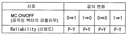
도 44는 움직임 벡터의 검출의 유무와 신뢰도와의 관계의 한 예를 도시하는 도면.Fig. 44 is a diagram showing an example of the relationship between the presence or absence of detection of a motion vector and reliability;
도 45는 움직임 벡터의 검출의 유무와 신뢰도와의 관계의 한 예를 도시하는 타이밍 파형도.45 is a timing waveform diagram illustrating an example of a relationship between the presence or absence of detection of a motion vector and reliability;
도 46은 신뢰도의 크기에 따른 움직임 벡터에 곱하는 게인 변화의 한 예를 도시하는 타이밍도.46 is a timing diagram illustrating an example of a gain change multiplied by a motion vector according to the magnitude of reliability.
도 47은 신뢰도의 크기에 따른 움직임 벡터에 곱하는 게인 변화의 다른 예를 도시하는 타이밍도.Fig. 47 is a timing chart showing another example of a gain change multiplied by a motion vector according to the magnitude of the reliability.
도 48은 본 발명의 제 4의 실시의 형태에 관한 화상 표시 장치의 구성의 한 예를 도시하는 블록도.48 is a block diagram illustrating an example of a configuration of an image display device according to a fourth embodiment of the present invention.
도 49는 도 48에 도시한 백라이트 구동부에 의한 프레임 단위의 흑삽입 처리(블링킹 처리)의 한 예를 도시하는 타이밍도.FIG. 49 is a timing diagram showing an example of black insertion processing (blinking processing) in units of frames by the backlight driver shown in FIG. 48; FIG.
도 50은 도 48에 도시한 백라이트 구동부에 의한 흑삽입 라인 단위의 흑삽입 처리(블링킹 처리)의 한 예를 도시하는 타이밍도.FIG. 50 is a timing diagram showing an example of black insertion processing (blinking processing) in units of black insertion lines by the backlight driver shown in FIG. 48; FIG.
도 51은 도 48에 도시한 백라이트 구동부에 의한 흑삽입 라인 단위와 프레임 단위를 조합시킨 흑삽입 처리(블링킹 처리)의 한 예를 도시하는 타이밍도.FIG. 51 is a timing diagram showing an example of black insertion processing (blinking processing) in which the black insertion line unit and the frame unit by the backlight driver shown in FIG. 48 are combined;
도 52는 프레임 단위의 흑삽입 처리에서의 흑삽입율의 한 예를 도시하는 타이밍도.52 is a timing chart illustrating an example of the black insertion rate in the black insertion process in units of frames.
도 53은 프레임 단위의 흑삽입 처리에서의 흑삽입율의 다른 예를 도시하는 타이밍도.53 is a timing diagram illustrating another example of the black insertion rate in the black insertion process in units of frames.
도 54는 흑삽입 라인 단위와 프레임 단위를 조합시킨 흑삽입 처리에서의 흑삽입율의 한 예를 도시하는 타이밍도.54 is a timing diagram illustrating an example of the black insertion rate in the black insertion process in which the black insertion line unit and the frame unit are combined.
도 55는 흑삽입 라인 단위와 프레임 단위를 조합시킨 흑삽입 처리에서의 흑삽입율의 다른 예를 도시하는 타이밍도.Fig. 55 is a timing chart illustrating another example of the black insertion rate in the black insertion process in which the black insertion line unit and the frame unit are combined.
도 56은 화면 전체의 휘도 히스토그램 분포의 한 예를 도시하는 특성도.Fig. 56 is a characteristic diagram showing an example of the luminance histogram distribution of the entire screen;
도 57은 제 4의 실시의 형태의 변형예에 관한 화상 표시 장치의 구성의 한 예를 도시하는 블록도.57 is a block diagram illustrating an example of a configuration of an image display device according to a modification of the fourth embodiment.
도 58은 본 발명이 적용되는 영상 신호 처리 장치의 전부 또는 일부분의 하드웨어 구성의 한 예를 도시하는 블록도.58 is a block diagram showing an example of a hardware configuration of all or a part of a video signal processing apparatus to which the present invention is applied.
이하, 본 발명의 실시의 형태에 관해, 도면을 참조하여 상세히 설명한다.EMBODIMENT OF THE INVENTION Hereinafter, embodiment of this invention is described in detail with reference to drawings.
[제 1의 실시의 형태][First Embodiment]
도 5는, 본 발명의 제 1의 실시의 형태에 관한 영상 신호 처리 장치(영상 신호 처리 장치(4))의 회로 구성예를 도시하는 블록도이다. 이 영상 신호 처리 장 치(4)는, 텔레비전 수신기에 내장되어 있는 것이고, 도시하지 않은 튜너, 디코더 등에서의 선국, 디코드 등의 처리를 거친 디지털 컴포넌트 신호(YUV)가 이 영상 신호 처리 장치(4)에 공급된다.5 is a block diagram showing an example of a circuit configuration of a video signal processing device (video signal processing device 4) according to the first embodiment of the present invention. The video signal processing unit 4 is built in a television receiver, and the digital component signal (YUV) which has been subjected to processing such as tuning and decoding by a tuner, decoder, etc., not shown, is the video signal processing unit 4. Supplied to.
이 영상 신호 처리 장치(4)에 공급된 디지털 컴포넌트 신호(YUV)는, 전처리부(41)에 입력함과 함께, 메모리 컨트롤러(42)를 통하여 메모리(43)에 순차로 기록된다.The digital component signal YUV supplied to the video signal processing apparatus 4 is input to the preprocessor 41 and sequentially recorded in the memory 43 via the memory controller 42.
전처리부(41)에서는, 디지털 컴포넌트 신호(YUV)로부터 휘도 신호(Y)를 분리하는 처리가 행하여진다. 전처리부(41)에서 분리된 휘도 신호(Y)도, 메모리 컨트롤러(42)를 통하여 메모리(43)에 순차로 기록된다.In the preprocessor 41, a process of separating the luminance signal Y from the digital component signal YUV is performed. The luminance signal Y separated by the preprocessor 41 is also sequentially recorded in the memory 43 via the memory controller 42.
메모리(43)에 기록된 휘도 신호(Y)는, 메모리 컨트롤러(42)에 의해 순차로 판독되고(도 2, 도 3에 도시한 바와 같이 같은 오리지널 프레임이 2회 또는 3회 반복되는 필름 신호인 경우에는, 같은 오리지널 프레임은 1회만 판독되고), 움직임 벡터 검출부(44)에 보내진다. 움직임 벡터 검출부(44)에서는, 현재의 프레임의 휘도 신호(Y)와 그 전후의 프레임의 휘도 신호(Y)를 이용하여, 블록 매칭에 의한 움직임 벡터 검출 처리가 행하여진다.The luminance signal Y recorded in the memory 43 is a film signal that is sequentially read by the memory controller 42 (the same original frame is repeated two or three times as shown in FIGS. 2 and 3). In this case, the same original frame is read only once) and sent to the motion vector detector 44. The motion vector detection unit 44 performs a motion vector detection process by block matching using the luminance signal Y of the current frame and the luminance signal Y of the frame before and after.
움직임 벡터 검출부(44)에서 검출된 각 프레임의 움직임 벡터(mv)는, 메모리 컨트롤러(42)를 통하여 메모리(43)에 기록된 후, 메모리(43)로부터 판독되어, 다음 프레임의 움직임 벡터 검출에서의 참조용으로 재차 움직임 벡터 검출부(44)에 보내진다.The motion vector mv of each frame detected by the motion vector detector 44 is recorded in the memory 43 through the memory controller 42 and then read from the memory 43 to detect the motion vector of the next frame. Is sent to the motion vector detector 44 again for reference.
또한, 메모리 컨트롤러(42)는, 메모리(43)에 기록한 디지털 컴포넌트 신 호(YUV)를, 2배속으로, 서로 1프레임분씩 비켜 놓고 2계통분 판독한다(도 2, 도 3에 도시한 바와 같이 같은 오리지널 프레임이 2회 또는 3회 반복되는 필름 신호인 경우에는, 같은 오리지널 프레임은 1회만 판독한다). 또한, 메모리 컨트롤러(42)는, 이 2개의 프레임 사이의 움직임을 나타내는 움직임 벡터(mv)를, 2배속으로 판독한다. 이렇게 판독된 2계통의 디지털 컴포넌트 신호(2YUV)와 움직임 벡터(mv)는, 보간부(45)에 보내진다.In addition, the memory controller 42 reads the digital component signal (YUV) recorded in the memory 43 at two times, one frame apart from each other, and reads two systems (as shown in FIGS. 2 and 3). If the same original frame is a film signal repeated twice or three times, the same original frame is read only once). The memory controller 42 also reads the motion vector mv representing the motion between these two frames at twice the speed. The two-system digital component signal 2YUV and the motion vector mv thus read are sent to the interpolator 45.
보간부(45)에는, 2계통의 서치 레인지 메모리(451, 452)와, 인터폴레이터(453)가 마련되어 있다. 메모리 컨트롤러(42)로부터의 2계통의 디지털 컴포넌트 신호(2YUV)는, 서치 레인지 메모리(451, 452)에 1계통씩 기록된다. 메모리 컨트롤러(42)로부터의 움직임 벡터(mv)는, 인터폴레이터(453)에 입력한다.The interpolation section 45 includes two search range memories 451 and 452 and an interpolator 453. Two systems of digital component signals 2YUV from the memory controller 42 are recorded one by one in the search range memories 451 and 452. The motion vector mv from the memory controller 42 is input to the interpolator 453.
또한, 텔레비전 수신기 내의 CPU(46)로부터는, 보간 프레임에서의 영상의 보간 위치를 나타내는 보간 위치 파라미터 Relpos가, 시리얼 버스인 I2C 버스(40)와, 시리얼 신호를 패럴렐 변환하는 디코더(47)를 통하여, 보간부(45)에 공급된다(보간 위치 파라미터 Relpos의 상세에 관해서는 후술한다). 이 보간 위치 파라미터 Relpos도, 인터폴레이터(453)에 입력한다.In addition, from the CPU 46 in the television receiver, the interpolation position parameter Relpos indicating the interpolation position of the video in the interpolation frame is an I 2 C bus 40 which is a serial bus and a decoder 47 for parallel converting serial signals. The interpolation section 45 is supplied to the interpolation section 45 (the details of the interpolation position parameter Relpos will be described later). The interpolation position parameter Relpos is also input to the interpolator 453.
인터폴레이터(453)는, 움직임 벡터(mv)와 보간 위치 파라미터 Relpos에 의거하여, 보간 프레임의 화소치를 계산하기 위해 이용하는 서치 레인지 메모리(451, 452) 내의 오리지널 프레임의 화소의 어드레스를 계산한다.Based on the motion vector mv and the interpolation position parameter Relpos, the interpolator 453 calculates the address of the pixel of the original frame in the search range memories 451 and 452 used to calculate the pixel value of the interpolation frame.
도 6은, 이 어드레스 계산의 원리를 개념적으로 도시하는 도면이다. n-1은, 서치 레인지 메모리(451, 452) 내에 기록된 1프레임분 빗나간 2개의 오리지널 프레임중 시간적으로 빠른 쪽의 오리지널 프레임의 각 화소의 어드레스(화면상에서의 x방향 및 y방향의 위치)를 종축 방향으로 나타내고 있다. n은, 이 2개의 오리지널 프레임중 시간적으로 느린 쪽의 오리지널 프레임의 각 화소의 어드레스를 종축 방향으로 나타내고 있다.6 is a diagram conceptually showing the principle of this address calculation. n-1 indicates the address (position in the x-direction and y-direction on the screen) of each pixel of the original frame, which is earlier in time, out of two original frames missed for one frame recorded in the search range memories 451 and 452. It is shown in the vertical axis direction. n represents the address of each pixel of the original frame of a slower time among these two original frames in the vertical axis direction.
i는, 보간 프레임의 각 화소의 어드레스를 종축 방향으로 나타내고 있다. 횡축은 시간이고, 오리지널 프레임(n-1, n) 사이에서의 보간 프레임(i)의 타이밍(여기서는, 한 예로서, 도 2(b)에서의 3개의 보간 프레임중의 중앙의 보간 프레임에 상당하는 타이밍)을 나타내고 있다. Relpos는, 보간 프레임(i)의 작성을 위해 공급된 보간 위치 파라미터이다.i indicates the address of each pixel of the interpolation frame in the vertical axis direction. The horizontal axis is time and corresponds to the timing of the interpolation frame i between the original frames n-1 and n (here, for example, corresponding to the center interpolation frame among three interpolation frames in FIG. 2 (b)). Timing). Relpos is an interpolation position parameter supplied for the creation of the interpolation frame i.
mv(x,y)int는, 보간 프레임(i)중 각 화소중, 현재 작성하려고 하고 있는 화소(기준 화소라고 칭함)의 어드레스(x, y)에 관한 오리지널 프레임(n-1, n) 사이의 움직임 벡터(mv)이다. zeroPelPrev(x, y)는, 오리지널 프레임(n-1)에서의 기준 어드레스(x, y)의 화소의 값이다. zeroPelSucc(x, y)는, 오리지널 프레임(n)에서의 기준 어드레스(x, y)의 화소의 값이다.mv (x, y) int is between the original frames n-1 and n for the addresses (x, y) of the pixels (referred to as reference pixels) of the current pixel to be created among the pixels in the interpolation frame i. Is the motion vector (mv). zeroPelPrev (x, y) is the value of the pixel of the reference address (x, y) in the original frame n-1. zeroPelSucc (x, y) is the value of the pixel of the reference address (x, y) in the original frame n.
인터폴레이터(453)는, 이 기준 어드레스(x, y)와, 움직임 벡터(mv(x,y)int)의 x방향 성분(mvX)과, 움직임 벡터(mv(x,y)int)의 y방향 성분(mvY)과, 보간 위치 파라미터 Relpos에 의거하여, 하기한 계산식(1)에 의해, 기준 어드레스(x, y)의 화소치를 계산하기 위해 이용하는 오리지널 프레임(n-1, n)의 화소의 어드레스를 구한다.The interpolator 453 includes the reference address (x, y), the x-direction component (mvX) of the motion vector (mv (x, y) int), and the y of the motion vector (mv (x, y) int). On the basis of the direction component mvY and the interpolation position parameter Relpos, the pixel of the original frame (n-1, n) used for calculating the pixel value of the reference address (x, y) is calculated by the following formula (1). Get the address.
오리지널 프레임(n-1)의 화소의 어드레스Address of pixel of original frame n-1
=(x+mvX·Relpos, y+mvY·Relpos)= (x + mvXRelpos, y + mvYRelpos)
오리지널 프레임(n)의 화소의 어드레스Address of pixel of original frame n
=(x-mvX·(1-Relpos), y-mvY·(1-Relpos)) … (1)= (x-mvX · (1-Relpos), y-mvY · (1-Relpos)) (One)
인터폴레이터(453)는, 이렇게 구한 어드레스를 서치 레인지 메모리(451, 452)에 보내어, 이들의 어드레스의 화소치(prev, succ)를 판독한다. 그리고, 이들의 화소치(prev, succ)와 보간 위치 파라미터 Relpos를 이용하여, 하기한 계산식(2)에 의해 보간 프레임(i)의 기준 어드레스(x, y)의 화소치(Out)의 계산을 행한다.The interpolator 453 sends the address thus obtained to the search range memories 451 and 452 to read the pixel values prev and succ of these addresses. Then, using these pixel values prev and succ and the interpolation position parameter Relpos, the pixel values Out of the reference addresses x and y of the interpolated frame i are calculated by the following formula (2). Do it.
Out=prev·(1-Relpos)+succ·Relpos … (2)Out = prev (1-Relpos) + succ. (2)
이러한 계산을, 보간 프레임(i)의 각 화소에 관해 순차로 행함(기준 어드레스의 값(x, y)을 순차로 갱신하여 행한다)에 의해, 보간 프레임(i)이 작성된다.Such calculation is performed sequentially for each pixel of the interpolation frame i (interpolation frame i is created by sequentially updating the values (x, y) of the reference address).
다음에, CPU(46)가 보간부(45)에 공급하는 보간 위치 파라미터 Relpos에 관해 설명한다. 도 7은, CPU(46)가 공급하는 보간 위치 파라미터 Relpos를 도시하는 도면이다. 도 5의 영상 신호 처리 장치(4)에 디지털 컴포넌트 신호(YUV)로서 2:2 풀다운 필름 신호(도 2(a) 참조)가 공급되는 경우에는, CPU(46)는, Relpos_22_0, Relpos_22_1, Relpos_22_2, Relpos_22_3이라는 4상(相)의 파라미터를 1/100sec마다(즉 1/25sec 주기로) 공급한다. 각 상의 파라미터는, 각각 6비트이다(도면중의 [5:0]은 6비트를 나타내고 있다).Next, the interpolation position parameter Relpos supplied by the CPU 46 to the interpolation section 45 will be described. 7 is a diagram illustrating the interpolation position parameter Relpos supplied by the CPU 46. When the 2: 2 pull-down film signal (see FIG. 2 (a)) is supplied to the video signal processing device 4 of FIG. 5 as the digital component signal YUV, the CPU 46 is Relpos_22_0, Relpos_22_1, Relpos_22_2, A four-phase parameter of Relpos_22_3 is supplied every 1/100 sec (that is, at 1/25 sec period). Each phase parameter is 6 bits each ([5: 0] in the figure represents 6 bits).
Relpos_22_0은, 서치 레인지 메모리(451, 452) 내의 1프레임분 빗나간 2개의 오리지널 프레임중의 시간적으로 빠른 쪽의 오리지널 프레임을 그대로 인터폴레이터(453)로부터 출력시키기 위한 파라미터이다. Relpos_22_1 내지 Relpos_22_3은, 이 2개의 오리지널 프레임 사이에 도 2(b)에 도시한 바와 같이 1/100sec 간격으로 3개의 보간 프레임을 작성하기 위한 파라미터이다.Relpos_22_0 is a parameter for outputting, from the interpolator 453, the original frame, which is earlier in time, among the two original frames missed by one frame in the search range memories 451 and 452. Relpos_22_1 to Relpos_22_3 are parameters for creating three interpolation frames at intervals of 1/100 sec as shown in Fig. 2B between these two original frames.
2:2 풀다운 필름 신호가 공급되는 경우에는, 서치 레인지 메모리(451, 452)(도 5)에는, 같은 오리지널 프레임이 1/25sec동안 보존된다. 그리고, 이 1/25sec동안에, Relpos_22_0, Relpos_22_1, Relpos_22_2, Relpos_22_3이라는 각 상의 파라미터마다, 인터폴레이터(453)가 앞에 나타낸 식(1) 및 식(2)에 의해 보간 프레임의 계산을 행한다. 이러한 처리가 1/25sec 주기로 반복됨에 의해, 2:2 풀다운 필름 신호가 프레임 레이트 변환된다.When a 2: 2 pulldown film signal is supplied, the same original frame is stored for 1/25 sec in the search range memories 451 and 452 (FIG. 5). During this 1/25 sec, the interpolator 453 calculates the interpolation frame by the equations (1) and (2) described above for each of the parameters of Relpos_22_0, Relpos_22_1, Relpos_22_2, and Relpos_22_3. By repeating this process in 1/25 sec periods, the 2: 2 pulldown film signal is frame rate converted.
다른 한편, 도 5의 영상 신호 처리 장치(4)에 디지털 컴포넌트 신호(YUV)로서 3:2 풀다운 필름 신호(도 3(a) 참조)가 공급되는 경우에는, CPU(46)는, Relpos_32_0, Relpos_32_1, Relpos_32_2, Relpos_32_3, Relpos_32_4라는 5상의 보간 위치 파라미터를 1/120sec마다(즉 1/24sec 주기로) 공급한다.On the other hand, when the 3: 2 pull-down film signal (see FIG. 3 (a)) is supplied to the video signal processing apparatus 4 of FIG. 5 as the digital component signal YUV, the CPU 46 is Relpos_32_0 and Relpos_32_1. The 5-phase interpolation position parameters Relpos_32_2, Relpos_32_3, and Relpos_32_4 are supplied every 1/120 sec (that is, at 1/24 sec period).
Relpos_32_0은, 서치 레인지 메모리(451, 452) 내의 1프레임분 빗나간 2개의 오리지널 프레임중의 시간적으로 빠른 쪽의 오리지널 프레임을 그대로 인터폴레이터(453)로부터 출력시키기 위한 파라미터이다. Relpos_32_1 내지 Relpos_32_4는, 이 2개의 오리지널 프레임 사이에 도 3(b)에 도시한 바와 같이 1/120sec 간격으로 4개의 보간 프레임을 작성하기 위한 파라미터이다.Relpos_32_0 is a parameter for outputting, from the interpolator 453, the original frame, which is earlier in time, among the two original frames missed by one frame in the search range memories 451 and 452. Relpos_32_1 to Relpos_32_4 are parameters for creating four interpolation frames at intervals of 1/120 sec, as shown in Fig. 3B between these two original frames.
3:2 풀다운 필름 신호가 공급되는 경우에는, 서치 레인지 메모리(451, 452) 에는, 같은 오리지널 프레임이 1/24sec동안 보존된다. 그리고, 이 1/24sec동안에, Relpos_32_0, Relpos_32_1, Relpos_32_2, Relpos_32_3, Relpos_32_4라는 각 상의 파라미터마다, 인터폴레이터(453)가 앞에 나타낸 식(1) 및 식(2)에 의해 보간 프레임의 계산을 행한다. 이러한 처리가 1/24sec 주기로 반복됨에 의해, 3:2 풀다운 필름 신호가 프레임 레이트 변환된다.When the 3: 2 pulldown film signal is supplied, the same original frame is stored in the search range memories 451 and 452 for 1/24 sec. During this 1/24 sec, the interpolator 453 calculates the interpolation frame by the equations (1) and (2) described above for each of the parameters of Relpos_32_0, Relpos_32_1, Relpos_32_2, Relpos_32_3, and Relpos_32_4. By repeating this process in 1/24 sec periods, the 3: 2 pulldown film signal is frame rate converted.
보간 위치 파라미터 Relpos의 값은, 유저가 선택하도록 되어 있다. 즉, 도 5에 도시하는 바와 같이, 텔레비전 수신기에 부속한 리모트 컨트롤러(400)에는, 보간 위치 파라미터 Relpos의 값을 「강·중·약」의 3단계로 전환하여 선택하기 위한 보간 위치 조정 버튼(401)이 마련되어 있다.The value of the interpolation position parameter Relpos is selected by the user. That is, as shown in Fig. 5, the remote controller 400 attached to the television receiver has an interpolation position adjustment button for switching and selecting the value of the interpolation position parameter Relpos in three stages of "strong, medium, and weak". 401 is provided.
이 보간 위치 조정 버튼(401)에서의 선택 결과를 나타내는 신호가, 리모트 컨트롤러(400)로부터 텔레비전 수신기 내의 적외선 수광 유닛(48)에서 수광되고, I2C 버스(40)를 통하여 CPU(46)에 보내지면, CPU(46)는, 그 선택 결과에 따른 보간 위치 파라미터 Relpos의 값을 설정한다.The signal indicating the result of the selection at the interpolation position adjustment button 401 is received by the infrared light receiving unit 48 in the television receiver from the remote controller 400 and is sent to the CPU 46 via the I 2 C bus 40. When sent, the CPU 46 sets the value of the interpolation position parameter Relpos in accordance with the selection result.
도 8은, 3:2 풀다운 필름 신호가 공급되는 경우에, 보간 위치 조정 버튼(401)에서의 선택 결과에 대응하여 CPU(46)가 설정하는 보간 위치 파라미터 Relpos의 값을 도시하는 도면이다. 보간 위치 조정 버튼(401)으로 「강」이 선택된 경우에는, Relpos_32_0, Relpos_32_1, Relpos_32_2, Relpos_32_3, Relpos_32_4의 값은 각각 0, 0.2, 0.4, 0.6, 0.8로 설정된다.FIG. 8: is a figure which shows the value of the interpolation position parameter Relpos which CPU 46 sets corresponding to the selection result in the interpolation position adjustment button 401, when 3: 2 pulldown film signal is supplied. When "strong" is selected by the interpolation position adjustment button 401, the values of Relpos_32_0, Relpos_32_1, Relpos_32_2, Relpos_32_3, and Relpos_32_4 are set to 0, 0.2, 0.4, 0.6, and 0.8, respectively.
1상째의 파라미터 Relpos_32_0의 값은 0이므로, 앞에 나타낸 식(1) 및 식(2) 로부터, 서치 레인지 메모리(451, 452) 내의 2개의 오리지널 프레임중 시간적으로 빠른 쪽의 오리지널 프레임이 그대로 인터폴레이터(453)로부터 출력된다.Since the value of the first phase parameter Relpos_32_0 is 0, from the above equations (1) and (2), among the two original frames in the search range memories 451 and 452, the original frame, which is earlier in time, is the interpolator ( 453).
또한, 2상째, 3상째, 4상째, 5상째의 파라미터 Relpos_32_1, Relpos_32_2, Relpos_32-3, Relpos_32_4의 값은 0.2, 0.4, 0.6, 0.8이라는 바와 같이 0.2씩 균등하게 변화하고 있기 때문에, 앞에 나타낸 식(1) 및 식(2)로부터, 서치 레인지 메모리(451, 452) 내의 2개의 오리지널 프레임 사이에 작성되는 4개의 보간 프레임에서의 영상의 보간 위치는, 도 3(b)에 도시한 종래의 보간 위치와 같이, 이 2개의 오리지널 프레임 사이의 영상의 움직임의 크기를 균등하게 5분할한 위치, 즉 이 움직임의 크기에 대해 각각 20%, 40%, 60%, 80%의 위치가 된다.In addition, since the values of the parameters Relpos_32_1, Relpos_32_2, Relpos_32-3, and Relpos_32_4 in the second, third, fourth, and fifth phases are uniformly changed by 0.2 as 0.2, 0.4, 0.6, and 0.8, From 1) and equation (2), the interpolation position of an image in four interpolation frames created between two original frames in the search range memories 451 and 452 is the conventional interpolation position shown in Fig. 3B. As shown above, the positions of the motions of the image between the two original frames are equally divided by five, that is, the positions of 20%, 40%, 60%, and 80%, respectively, with respect to the size of the motions.
보간 위치 조정 버튼(401)으로 「중」이 선택된 경우에는, Relpos_32_0, Relpos_32_1, Relpos_32_2, Relpos_32_3, Relpos_32_4의 값은 각각 0, 0.15, 0.3, 0.7, 0.85로 설정된다. 1상째의 파라미터Relpos_32_0의 값은 0이므로, 「강」인 경우와 같이, 서치 레인지 메모리(451, 452) 내의 2개의 오리지널 프레임중 시간적으로 빠른 쪽의 오리지널 프레임이 그대로 인터폴레이터(453)로부터 출력된다.When "middle" is selected by the interpolation position adjustment button 401, the values of Relpos_32_0, Relpos_32_1, Relpos_32_2, Relpos_32_3, and Relpos_32_4 are set to 0, 0.15, 0.3, 0.7, and 0.85, respectively. Since the value of the first phase parameter Relpos_32_0 is 0, the original frame, which is earlier in time, among the two original frames in the search range memories 451 and 452, is output from the interpolator 453 as it is in the case of "strong". .
이에 대해, 2상째, 3상째의 파라미터Relpos_32_1, Relpos_32_2(이것은, 도 3(b)에도 도시되어 있는 바와 같이, 이웃하는 오리지널 프레임 사이의 4개의 보간 프레임중, 전방의 오리지널 프레임에 가까운 쪽의 보간 프레임을 작성하기 위한 파라미터이다)의 값 0.15, 0.3은, 「강」인 경우의 값 0.2, 0.4보다도 작게 되어 있다.On the other hand, the parameters Relpos_32_1 and Relpos_32_2 in the second and third phases (this is also shown in Fig. 3 (b), among the four interpolation frames between neighboring original frames, the interpolation frame closer to the front original frame). The values of 0.15 and 0.3 are smaller than the values of 0.2 and 0.4 in the case of "strong".
또한, 4상째, 5상째의 파라미터Relpos_32_3, Relpos_32_4(이것은, 도 3(b)에 도 도시되어 있는 바와 같이, 이웃하는 오리지널 프레임 사이의 4개의 보간 프레임중, 후방의 오리지널 프레임에 가까운 쪽의 보간 프레임을 작성하기 위한 파라미터이다)의 값 0.7, 0.85은, 「강」인 경우의 값 0.6, 0.8보다도 크게 되어 있다.In addition, the parameters Relpos_32_3 and Relpos_32_4 of the 4th and 5th phases (this is also shown in Fig. 3 (b), of the four interpolation frames between neighboring original frames, the interpolation frame closer to the original frame of the rear side). Values 0.7 and 0.85 are larger than values 0.6 and 0.8 in the case of "strong".
이러한 파라미터Relpos_32_1 내지 Relpos_32_4의 값에 의해, 「중」인 경우에는, 서치 레인지 메모리(451, 452) 내의 2개의 오리지널 프레임 사이에 작성되는 4개의 보간 프레임에서의 영상의 보간 위치는, 이 2개의 오리지널 프레임 사이의 영상의 움직임의 크기에 대해 각각 15%, 30%, 70%, 85%의 위치가 된다. 즉, 4개의 보간 프레임에서의 영상의 보간 위치는, 「강」인 경우와 같이 이 2개의 오리지널 프레임 사이에서의 영상의 움직임의 크기를 균등하게 분할한 위치(종래와 같은 보간 위치)가 아니라, 이 균등하게 분할한 위치보다도 각각의 보간 프레임에 가까운 쪽의 오리지널 프레임의 영상 근처의 위치가 된다.According to the values of the parameters Relpos_32_1 to Relpos_32_4, when "medium", the interpolation positions of the video in the four interpolation frames created between the two original frames in the search range memories 451 and 452 are the two originals. The positions of the motions of the images between the frames are 15%, 30%, 70%, and 85%, respectively. That is, the interpolation position of the video in the four interpolation frames is not the position (the conventional interpolation position) where the magnitude of the motion of the video is uniformly divided between these two original frames as in the case of "strong". It becomes a position near the video of the original frame closer to each interpolation frame than this evenly divided position.
보간 위치 조정 버튼(401)으로 「약」이 선택된 경우에는, Relpos_32_0, Relpos_32_1, Relpos_32_2, Relpos_32_3, Relpos_32_4의 값은 각각 0, 0.1, 0.2, 0.8, 0.9로 설정된다. 2상째, 3상째의 파라미터(이웃하는 오리지널 프레임 사이의 4개의 보간 프레임중 전방의 오리지널 프레임에 가까운 쪽의 보간 프레임을 작성하기 위한 파라미터)의 값 0.1, 0.2은, 「중」인 경우의 값 0.15, 0.3보다도 더욱 작게 되어 있다.When "about" is selected by the interpolation position adjustment button 401, the values of Relpos_32_0, Relpos_32_1, Relpos_32_2, Relpos_32_3, and Relpos_32_4 are set to 0, 0.1, 0.2, 0.8, and 0.9, respectively. The values 0.1 and 0.2 of the second phase and third phase parameters (parameters for creating the interpolation frame closer to the original original frame among the four interpolation frames between neighboring original frames) are 0.15 for the case of "medium". , Smaller than 0.3.
또한, 4상째, 5상째의 파라미터(이웃하는 오리지널 프레임 사이의 4개의 보간 프레임중, 후방의 오리지널 프레임에 가까운 쪽의 보간 프레임을 작성하기 위한 파라미터)의 값 0.8, 0.9는, 「중」인 경우의 값 0.7, 0.85보다도 더욱 크게 되어 있다.In the case where the values 0.8 and 0.9 of the 4th and 5th parameters (parameters for creating an interpolation frame closer to the rear original frame among four interpolation frames between neighboring original frames) are "middle", The values are larger than 0.7 and 0.85.
이러한 파라미터 Relpos_32_1 내지 Relpos_32_4의 값에 의해, 「약」인 경우에는, 서치 레인지 메모리(451, 452) 내의 2개의 오리지널 프레임 사이에 작성되는 4개의 보간 프레임에서의 영상의 보간 위치는, 이 2개의 오리지널 프레임 사이의 영상의 움직임의 크기에 대해 각각 10%, 20%, 80%, 90%의 위치가 된다. 즉, 4개의 보간 프레임에서의 영상의 보간 위치는, 「중」인 경우보다도 한층, 각각의 보간 프레임에 가까운 쪽의 오리지널 프레임의 영상 근처의 위치가 된다.With the values of these parameters Relpos_32_1 to Relpos_32_4, when "weak", the interpolation positions of the video in the four interpolation frames created between the two original frames in the search range memories 451 and 452 are the two originals. 10%, 20%, 80%, and 90% of the position of the movement of the image between the frames, respectively. In other words, the interpolation position of the video in the four interpolation frames becomes a position near the video of the original frame closer to each interpolation frame than in the case of "middle".
도 9는, 2:2 풀다운 필름 신호가 공급되는 경우에, 보간 위치 조정 버튼(401)에서의 선택 결과에 대응하여 CPU(46)가 설정하는 보간 위치 파라미터 Relpos의 값을 도시하는 도면이다. 보간 위치 조정 버튼(401)으로 「강」이 선택된 경우에는, Relpos_22_0, Relpos_22_1, Relpos_22_2, Relpos_22_3의 값은 각각 0, 0.25, 0.5, 0.75로 설정된다.9 is a diagram showing the value of the interpolation position parameter Relpos set by the CPU 46 in response to the selection result at the interpolation position adjustment button 401 when a 2: 2 pulldown film signal is supplied. When "strong" is selected by the interpolation position adjustment button 401, the values of Relpos_22_0, Relpos_22_1, Relpos_22_2, and Relpos_22_3 are set to 0, 0.25, 0.5, and 0.75, respectively.
1상째의 파라미터 Relpos_22_0의 값은 0이므로, 서치 레인지 메모리(451, 452) 내의 2개의 오리지널 프레임중 시간적으로 빠른 쪽의 오리지널 프레임이 그대로 인터폴레이터(453)로부터 출력된다.Since the value of the first phase parameter Relpos_22_0 is 0, the original frame, which is earlier in time among the two original frames in the search range memories 451 and 452, is output from the interpolator 453 as it is.
또한, 2상째, 3상째, 4상째의 파라미터 Relpos_22_1, Relpos_22_2, Relpos_22_3의 값은 0.25, 0.5, 0.75라는 바와 같이 0.25씩 균등하게 변화하고 있기 때문에, 앞에 나타낸 식(1) 및 식(2) 로부터, 서치 레인지 메모리(451, 452) 내의 2개의 오리지널 프레임 사이에 작성되는 3개의 보간 프레임에서의 영상의 보간 위치는, 도 2(b)에 도시한 종래의 보간 위치와 같이, 이 2개의 오리지널 프레임 사 이의 영상의 움직임의 크기를 균등하게 4분할 한 위치, 즉 이 움직임의 크기에 대해 각각 25%, 50%, 75%의 위치가 된다.In addition, since the values of the parameters Relpos_22_1, Relpos_22_2, and Relpos_22_3 in the second, third, and fourth phases are uniformly changed by 0.25, such as 0.25, 0.5, and 0.75, from the above formulas (1) and (2), The interpolation positions of the images in the three interpolation frames created between the two original frames in the search range memories 451 and 452 are the same as those of the conventional interpolation positions shown in Fig. 2B. The size of the motion of the image is equally divided into four positions, that is, 25%, 50%, and 75% of the size of the movement, respectively.
보간 위치 조정 버튼(401)으로 「중」이 선택된 경우에는, Relpos_22_0, Relpos_22_1, Relpos_22_2, Relpos_22_3의 값은 각각 0, 0.15, 0.3, 0.85로 설정된다. 1상째의 파라미터 Relpos_22_0의 값은 0이므로, 「강」인 경우와 같이, 서치 레인지 메모리(451, 452) 내의 2개의 오리지널 프레임 중 시간적으로 빠른 쪽의 오리지널 프레임이 그대로 인터폴레이터(453) 로부터 출력된다.When "middle" is selected by the interpolation position adjustment button 401, the values of Relpos_22_0, Relpos_22_1, Relpos_22_2, and Relpos_22_3 are set to 0, 0.15, 0.3, and 0.85, respectively. Since the value of the first phase parameter Relpos_22_0 is 0, as in the case of " strong ", the original frame, which is earlier in time, among the two original frames in the search range memories 451 and 452, is output from the interpolator 453 as it is. .
이에 대해, 2상째의 파라미터 Relpos_22_1(이것은, 도 2(b)에도 도시되어 있는 바와 같이, 이웃하는 오리지널 프레임 사이의 3개의 보간 프레임중, 전방의 오리지널 프레임에 가까운 쪽의 보간 프레임을 작성하기 위한 파라미터이다)의 값 0.15는, 「강」인 경우의 값 0.25보다도 작게 되어 있다.On the other hand, the second phase parameter Relpos_22_1 (this is also a parameter for creating an interpolation frame closer to the original original frame among three interpolation frames between neighboring original frames, as shown in Fig. 2 (b)). Value) is smaller than the value 0.25 in the case of "strong".
또한, 3상째의 파라미터 Relpos_22_2는, 도 2(b)에도 도시되어 있는 바와 같이, 이웃하는 오리지널 프레임 사이의 3개의 보간 프레임중, 전방의 오리지널 프레임과 후방의 오리지널 프레임의 정확히 중간의 보간 프레임을 작성하기 위한 파라미터이다. 여기서는, 이 중간의 보간 프레임도, 전방의 오리지널 프레임에 가까운 쪽의 보간 프레임으로 분류함에 의해, 파라미터 Relpos_22_2의 값도, 「강」인 경우의 값 0.5보다도 작은 값 0.3이 되어 있다.In addition, as shown in Fig. 2 (b), the third-phase parameter Relpos_22_2 creates an interpolation frame that is exactly halfway between the front original frame and the rear original frame, among three interpolation frames between neighboring original frames. Parameters to do this. Here, the intermediate interpolation frame is also classified into the interpolation frame closer to the original original frame, so that the value of the parameter Relpos_22_2 is also smaller than the value 0.5 in the case of "strong".
또한, 4상째의 파라미터 Relpos_22_3(이것은, 도 2(b)에도 도시되어 있는 바와 같이, 이웃하는 오리지널 프레임 사이의 3개의 보간 프레임중, 후방의 오리지널 프레임에 가까운 쪽의 보간 프레임을 작성하기 위한 파라미터이다)의 값 0.85은, 「강」인 경우의 값 0.75보다도 크게 되어 있다.In addition, the fourth phase parameter Relpos_22_3 (this is a parameter for creating an interpolation frame closer to the rear original frame among three interpolation frames between neighboring original frames, as shown in Fig. 2B). Value 0.85 is larger than the value 0.75 in the case of "strong".
이러한 파라미터 Relpos_22_1 내지 Relpos_22_3의 값에 의해, 「중」인 경우에는, 서치 레인지 메모리(451, 452) 내의 2개의 오리지널 프레임 사이에 작성되는 3개의 보간 프레임에서의 영상의 보간 위치는, 이 2개의 오리지널 프레임 사이의 영상의 움직임의 크기에 대해 각각 15%, 30%, 85%의 위치가 된다. 즉, 3개의 보간 프레임에서의 영상의 보간 위치는, 「강」인 경우와 같이 이 2개의 오리지널 프레임 사이에서의 영상의 움직임의 크기를 균등하게 분할한 위치(종래와 같은 보간 위치)가 아니라, 이 균등하게 분할한 위치보다도 각각의 보간 프레임에 가까운 쪽의 오리지널 프레임의 영상 근처의 위치가 된다.According to the values of these parameters Relpos_22_1 to Relpos_22_3, when "medium", the interpolation positions of the video in the three interpolation frames created between two original frames in the search range memories 451 and 452 are the two originals. The positions of the motions of the images between the frames are 15%, 30%, and 85%, respectively. That is, the interpolation position of the video in the three interpolation frames is not a position (a conventional interpolation position) where the magnitude of the motion of the video is uniformly divided between these two original frames as in the case of "strong". It becomes a position near the video of the original frame closer to each interpolation frame than this evenly divided position.
보간 위치 조정 버튼(401)으로 「약」이 선택된 경우에는, Relpos_22_0, Relpos_22_1, Relpos_22_2, Relpos_22_3의 값은 각각 0, 0.1, 0.2, 0.9로 설정된다. 2상째, 3상째의 파라미터(이웃하는 오리지널 프레임 사이의 3개의 보간 프레임중 전방의 오리지널 프레임에 가까운 쪽의 보간 프레임을 작성하기 위한 파라미터)의 값 0.1, 0.2은, 「중」인 경우의 값 0.15, 0.3보다도 더욱 작게 되어 있다.When "about" is selected by the interpolation position adjustment button 401, the values of Relpos_22_0, Relpos_22_1, Relpos_22_2, and Relpos_22_3 are set to 0, 0.1, 0.2, and 0.9, respectively. Values 0.1 and 0.2 of the second phase and third phase parameters (parameters for creating the interpolation frame closer to the original original frame among the three interpolation frames between neighboring original frames) are 0.15 when "medium". , Smaller than 0.3.
또한, 4상째의 파라미터(이웃하는 오리지널 프레임 사이의 3개의 보간 프레임중, 후방의 오리지널 프레임에 가까운 쪽의 보간 프레임을 작성하기 위한 파라미터)의 값 0.9는, 「중」인 경우의 값 0.85보다도 더욱 크게 되어 있다.In addition, the value 0.9 of the fourth phase parameter (a parameter for creating an interpolation frame closer to the rear original frame among three interpolation frames between neighboring original frames) is more than the value 0.85 of "medium". It is large.
이러한 파라미터 Relpos_22_1 내지 Relpos_22_3의 값에 의해, 「약」인 경우에는, 서치 레인지 메모리(451, 452) 내의 2개의 오리지널 프레임 사이에 작성되는 3개의 보간 프레임에서의 영상의 보간 위치는, 2개의 오리지널 프레임 사이의 영상 의 움직임의 크기에 대해 각각 10%, 20%, 90%의 위치가 된다. 즉, 3개의 보간 프레임에서의 영상의 보간 위치는, 「중」인 경우보다도 한층, 각각의 보간 프레임에 가까운 쪽의 오리지널 프레임의 영상 근처의 위치가 된다.By the values of these parameters Relpos_22_1 to Relpos_22_3, when "weak", the interpolation position of the video in the three interpolation frames created between two original frames in the search range memories 451 and 452 is two original frames. 10%, 20%, and 90% of the positions of the movements of the images in between are respectively. That is, the interpolation position of the video in three interpolation frames becomes a position near the video of the original frame closer to each interpolation frame than in the case of "middle".
도 10은, 도 4와 같은 오리지널 프레임의 영상을 예로 들어, 도 5의 영상 신호 처리 장치(4)에 3:2 풀다운 필름 신호가 공급되고 보간 위치 조정 버튼(401)으로 「약」이 선택된 경우의 프레임 레이트 변환 후의 영상(도 10(b))을, 종래의 보간 위치에서의 영상(도 10(a))과 대비시켜서 도시하는 도면이다.10 illustrates an image of an original frame as illustrated in FIG. 4, in which a 3: 2 pull-down film signal is supplied to the video signal processing device 4 of FIG. 5, and “about” is selected by the interpolation position adjustment button 401. Fig. 10 (b) shows a contrasted image (Fig. 10 (a)) at a conventional interpolation position.
도 10(b)에 도시되어 있는 바와 같이, 4개의 보간 프레임중, 전방의 오리지널 프레임(A)의 쪽에 가까운 2개의 보간 프레임에서는, 종래의 경우보다도 비행기의 영상이 오리지널 프레임(A) 근처에 위치하고 있다. 다른한편, 후방의 오리지널 프레임(B)의 쪽에 가까운 2개의 보간 프레임에서는, 종래의 경우보다도 비행기의 영상이 오리지널 프레임(B) 근처에 위치하고 있다. 따라서 2번째의 보간 프레임과 3번째의 보간 프레임 사이에서는, 비행기의 영상의 위치의 간격이 종래보다도 크게 되어 있다.As shown in Fig. 10 (b), in the two interpolation frames closer to the front original frame A among the four interpolation frames, the image of the plane is located near the original frame A than in the conventional case. have. On the other hand, in the two interpolation frames closer to the rear original frame B, the image of the airplane is located near the original frame B than in the conventional case. Therefore, the space | interval of the position of the video image of an airplane becomes larger between the 2nd interpolation frame and the 3rd interpolation frame than before.
이와 같이, 이 영상 신호 처리 장치(4)에서는, 보간 위치 조정 버튼(401)으로 「약」이나 「중」을 선택한 경우, 전후의 오리지널 프레임중의 전방의 오리지널 프레임에 가까운 보간 프레임에서는 보간 위치가 전방의 오리지널 프레임의 영상 근처로 치우치고, 후방의 오리지널 프레임에 가까운 보간 프레임에서는 보간 위치가 후방의 오리지널 프레임의 영상 근처로 치우친다.As described above, in the video signal processing apparatus 4, when "weak" or "medium" is selected by the interpolation position adjustment button 401, the interpolation position is determined in the interpolation frame close to the front original frame in the front and rear original frames. The interpolation position is shifted near the image of the rear original frame in the interpolation frame close to the rear original frame.
그 때문에, 도 10에도 도시되어 있는 바와 같이, 전방의 오리지널 프레임에 가까운 보간 프레임과, 후방의 오리지널 프레임에 가까운 보간 프레임 사이에서는, 종래보다도, 보간된 영상의 위치의 간격이 커진다.Therefore, as shown in FIG. 10, the space | interval of the position of an interpolated video becomes large between the interpolation frame which is close to the original frame of the front side, and the interpolation frame which is close to the rear original frame.
이와 같이, 종래보다도 영상의 보간 위치의 간격이 큰 보간 프레임이 존재하게 되기 때문에, 그들의 보간 프레임 사이에서의 영상의 움직임의 흔들림이 종래보다도 커진다. 따라서 필름 신호의 프레임 레이트 변환을 행할 때에, 프레임 레이트 변환에 의해 저더를 삭감하면서, 그 삭감의 정도를 종래보다도 약하게 할 수 있다.In this way, interpolation frames with larger intervals between the interpolation positions of the images exist than in the prior art, so that the motion of the movement of the images between these interpolation frames becomes larger than before. Therefore, when performing frame rate conversion of a film signal, the degree of the reduction can be made weaker than before while reducing the judder by frame rate conversion.
그리고, 유저가 텔레비전 수신기로 필름 신호의 영상을 보는 경우에, 저더를 대폭적으로 삭감하여 영상의 움직임을 스무스하게 하는 쪽이 좋다고 느끼는지, 그렇지 않으면 저더를 어느 정도 남겨둔 쪽이 필름 신호인 것 같아 좋다고 느끼는지는, 개개의 유저에 의해 기호를 알 수 있는 바이다. 그래서, 영상의 움직임이 스무스하게 된 쪽이 좋다고 느끼는 유저는 보간 위치 조정 버튼(401)으로 「강」을 선택하고, 저더를 어느 정도 남겨둔 쪽이 좋다고 느끼는 유저는 보간 위치 조정 버튼(401)으로 「약」이나 「중」을 선택함에 의해, 개개의 유저의 기호에 따라 저더의 삭감의 정도를 선택할 수 있다.And when the user views a film signal image on a television receiver, do you feel it is better to reduce the judder drastically to smooth the motion of the image, or do you feel that it is better to leave the judder the film signal? Is a symbol known to each user. Therefore, a user who feels that the motion of the video is smoother is selected by using the interpolation position adjustment button 401, and a user who feels that it is better to leave some judder by using the interpolation position adjustment button 401. By selecting "about" or "medium", the degree of reduction of the judder can be selected according to the preference of each user.
또한, [배경 기술]의 난에 기재한 바와 같이, 움직임 보상을 이용한 프레임 레이트 변환에서는, 이웃하는 오리지널 프레임 사이의 영상의 움직임이 매우 빨라진 경우, 움직임 벡터의 탐색 범위를 초과하여 버리기 때문에, 큰 저더가 발생한다. 그러한 경우에도, 보간 위치 조정 버튼(401)으로 「약」이나 「중」을 선택하여 저더의 삭감의 정도를 약하게 하여 두면, 원래 어느 정도 저더가 존재하는 영상을 보고 있는 도중에 큰 저더가 발생하기 때문에, 종래와 같이 움직임이 매우 스무 스한 영상을 보고 있는 도중에 돌연 큰 저더가 발생하는 경우보다도, 위화감을 느끼는 것이 적어진다.In addition, as described in the section of [Background Art], in frame rate conversion using motion compensation, when the motion of an image between neighboring original frames becomes very fast, the search range of the motion vector is exceeded. Occurs. Even in such a case, when "weak" or "medium" is selected with the interpolation position adjustment button 401 to reduce the degree of reduction of the judder, since a large judder is generated while viewing an image in which judder exists to some extent, As compared with the case where a large judder suddenly occurs while viewing an image in which motion is very smooth as in the prior art, it is less likely to feel discomfort.
또한, 움직임 보상을 이용한 프레임 레이트 변환에서는, 부작용으로서, 움직임이 있는 인물 등의 영상의 윤곽에 아지랑이와 같은 노이즈가 보이는 현상(Halo로 부르고 있다)가 생긴 것이 알려져 있는데, 이 Halo는, 보간되는 영상의 위치가 오리지널 프레임의 영상의 위치로부터 떨어질수록 현저해진다. 이에 대해, 보간 위치 조정 버튼(401)으로 「약」이나 「중」을 선택하면, 보간되는 영상의 위치가 오리지널 프레임의 영상 근처의 위치가 되기 때문에, 이 Halo도 억제할 수 있게 된다.In addition, in frame rate conversion using motion compensation, it is known that a side effect such as a haze appears in the outline of an image such as a moving person (called Halo) as a side effect. This Halo is an interpolated video. The more the position of is away from the position of the image of the original frame, the more pronounced. On the other hand, when "weak" or "medium" is selected by the interpolation position adjustment button 401, since the position of the interpolated video becomes the position near the video of the original frame, this Halo can also be suppressed.
또한, 도 5의 예에서는, 리모트 컨트롤러(400)에, 보간 위치 파라미터 Relpos의 값을 「강·중·약」의 3단계로 전환하여 선택하기 위한 보간 위치 조정 버튼(401)을 마련하고 있다. 그러나, 다른 예로서, 보간 위치 파라미터 Relpos의 값을 도 8이나 도 9의 「강」부터 「약」까지의 범위 내에서 연속적(무단계)으로 변화시켜서 선택하기 위한 볼륨 스위치 등의 조작 수단을, 리모트 컨트롤러(400) 또는 텔레비전 수신기 본체에 마련하도록 하여도 좋다. 또한, 그 경우에, 보간 위치 파라미터 Relpos의 값의 최소 변화량을 한층더 작게 하기 위해, CPU(46)가 공급하는 보간 위치 파라미터 Relpos의 비트 수를 6비트보다도 크게(예를 들면 8비트 정도로) 하여도 좋다.In the example of FIG. 5, the remote controller 400 is provided with an interpolation position adjusting button 401 for switching the value of the interpolation position parameter Relpos to three stages of "strong, medium, and weak". However, as another example, operating means such as a volume switch for continuously changing (selecting) the value of the interpolation position parameter Relpos in a range from "strong" to "weak" in FIGS. It may be provided in the controller 400 or the television receiver main body. In this case, in order to further reduce the minimum change amount of the value of the interpolation position parameter Relpos, the number of bits of the interpolation position parameter Relpos supplied by the CPU 46 is made larger than 6 bits (for example, about 8 bits). Also good.
다음에, 도 11은, 본 실시의 형태의 변형예에 관한 영상 신호 처리 장치(영상 신호 처리 장치(4A))의 회로 구성예를 도시하는 블록도이다. 또한, 도 5에 도시한 영상 신호 처리 장치(4)와 동일 구성의 부분에는 동일 부호를 붙이고 있고, 그 들의 중복 설명은 생략한다.Next, FIG. 11 is a block diagram which shows the example of the circuit structure of the video signal processing apparatus (video signal processing apparatus 4A) which concerns on the modification of this embodiment. In addition, the same code | symbol is attached | subjected to the part of the same structure as the video signal processing apparatus 4 shown in FIG. 5, and the duplication description is abbreviate | omitted.
이 영상 신호 처리 장치(4A)에서는, 영상 신호 처리 장치(4A)에 공급되는 디지털 컴포넌트 신호(YUV)의 S/N 레벨이, S/N 레벨 검출부(49)에서 검출된다. 그리고, 그 검출 결과를 나타내는 신호가, I2C 버스(40)를 통하여 CPU(46)에 보내진다.In this video signal processing apparatus 4A, the S / N level of the digital component signal YUV supplied to the video signal processing apparatus 4A is detected by the S / N level detection unit 49. The signal indicating the detection result is sent to the CPU 46 via the I 2 C bus 40.
움직임 보상을 이용한 프레임 레이트 변환에서는, 전술한 바와 같이, 움직임이 있는 인물 등의 영상의 윤곽에 아지랑이와 같은 노이즈가 보이는 현상(Halo)이 생긴다. 이 Halo는, 영상의 보간 위치가 오리지널 프레임의 영상의 위치로부터 떨어질수록 현저해지는 외에, 영상 신호의 S/N 레벨이 낮아질(노이즈 레벨이 높아질)수록 생기기 쉬워진다.In the frame rate conversion using motion compensation, as described above, a halo occurs in which noise such as a haze appears on the outline of an image of a moving person or the like. This Halo becomes more prominent as the interpolation position of the image is away from the position of the image of the original frame, and is more likely to occur as the S / N level of the video signal is lowered (the noise level is higher).
CPU(46) 내의 메모리에는, Halo가 생기기 쉬워지는지의 여부의 경계로서 미리 설정한 소정의 값의 S/N 레벨을 나타내는 정보가 미리 기억되고 있다. CPU(46)는, S/N 레벨 검출부(49)에서의 검출 결과가 이 소정 레벨보다도 높은 경우에는, 보간부(45)에 공급하는 보간 위치 파라미터 Relpos를, 도 8이나 도 9의 「강」의 값으로 설정한다. 다른 한편, S/N 레벨 검출부(49)에서의 검출 결과가 이 소정 레벨 이하인 경우에는, CPU(46)는, 보간부(45)에 공급하는 보간 위치 파라미터 Relpos를, 도 8이나 도 9의 「약」(또는 「중」이라도 좋다)의 값으로 설정한다.In the memory in the CPU 46, information indicating the S / N level of a predetermined value set in advance as a boundary of whether Halo is likely to occur is stored in advance. When the detection result by the S / N level detection unit 49 is higher than this predetermined level, the CPU 46 sets the interpolation position parameter Relpos supplied to the interpolation unit 45 to "strong" in FIGS. 8 and 9. Set to the value of. On the other hand, when the detection result by the S / N level detection unit 49 is equal to or less than this predetermined level, the CPU 46 sets the interpolation position parameter Relpos supplied to the interpolation unit 45 as shown in FIG. 8 or 9. It is set to the value of "about" (or "middle").
이로써, 공급되는 디지털 컴포넌트 신호(YUV)의 S/N 레벨이 높은 경우(Halo가 생기기 어려운 경우)에는, 영상의 움직임을 스무스하게 할 수 있고, 이 S/N 레벨이 낮은 경우(Halo가 생기기 쉬운 경우)에는, 영상의 보간 위치를 오리지널 프레 임의 영상 근처의 위치로 하여 Halo를 억제할 수 있다.Thus, when the S / N level of the supplied digital component signal YUV is high (Halo is unlikely to be generated), the motion of the image can be smoothed, and when this S / N level is low (Halo is easy to occur) In the case of), Halo can be suppressed by making the interpolation position of the video a position near the original frame random video.
또한, 본 실시의 형태에서는, 필름 신호를 프레임 레이트 변환하는 예를 설명하였다. 그러나, 카메라 신호에서도, 예를 들면 도 12에 도시하는 바와 같이, NTSC 방식의 카메라 신호의 프레임 레이트를 240Hz로 변환하는 경우에는, 이웃하는 오리지널 프레임(프레임(A)과 프레임(B)이나, 프레임(B)과 프레임(C)이나, 프레임(C)과 프레임(D))의 사이에, 1/240sec 간격으로 3개씩 보간 프레임이 추가된다. 또한, 도시는 생략하지만, PAL 방식의 카메라 신호의 프레임 레이트를 200Hz로 변환하는 경우에는, 이웃하는 오리지널 프레임 사이에, 1/200sec 간격으로 3개씩 보간 프레임이 추가된다. 본 발명은, 카메라 신호를 이와 같이 하이 프레임 레이트로 변환하는 경우에도 적용하면 좋다.In addition, in this embodiment, the example which frame-rate-converted a film signal was demonstrated. However, even in a camera signal, as shown in FIG. 12, when converting the frame rate of the NTSC system camera signal to 240 Hz, neighboring original frames (frame A, frame B, or frame) are shown. An interpolation frame is added three times at intervals of 1/240 sec between (B) and the frame (C) or between the frame (C) and the frame (D). Although not shown, when converting the frame rate of the PAL camera signal to 200 Hz, three interpolation frames are added at intervals of 1/200 sec. Between neighboring original frames. The present invention may also be applied to the case where the camera signal is converted to a high frame rate in this manner.
또한, 본 실시의 형태에서는, 유저의 선택 조작에 의해 보간 위치 파라미터 Relpos의 값을 설정하는 예나, 영상 신호의 S/N 레벨에 따라 보간 위치 파라미터 Relpos의 값을 설정하는 예를 설명하였다. 그러나, 보간 위치 파라미터 Relpos의 값의 또다른 설정 방법으로서, 예를 들면 현재 수신하고 있는 텔레비전 방송프로그램의 장르의 정보를 EPG(전자 방송프로그램 가이드)로부터 취득하고, 그 장르에 의해 보간 위치 파라미터 Relpos의 값을 설정하도록(예를 들면, 영상의 움직임이 느린 장르에서는 도 8이나 도 9의 「강」의 값으로 설정하고, 영상의 움직임이 빠른 장르에서는 도 8이나 도 9의 「약」 또는 「중」의 값으로 설정한다) 하여도 좋다.In the present embodiment, an example of setting the value of the interpolation position parameter Relpos by the user's selection operation or an example of setting the value of the interpolation position parameter Relpos in accordance with the S / N level of the video signal has been described. However, as another method of setting the value of the interpolation position parameter Relpos, for example, information on the genre of the television broadcast program currently received is obtained from the EPG (Electronic Broadcasting Program Guide), and the genre of the interpolation position parameter Relpos is determined according to the genre. To set the value (for example, in a genre where the motion of the video is slow, set to the value of "strong" in FIG. 8 or 9, and "weak" or "medium" in FIG. 8 or 9 in the fast motion of the video). Value).
혹은 또한, 보간 위치 파라미터 Relpos의 값을, 팩트 리셋으로 도 8이나 도 9의 「약」 또는 「중」의 값으로 설정하도록 하여도 좋다.Alternatively, the value of the interpolation position parameter Relpos may be set to "weak" or "medium" in Figs. 8 and 9 by fact reset.
또한, 도 8이나 도 9에 도시한 「약」이나 「중」의 값은 어디까지나 한 예이고, 그 이외 값으로서 각 보간 프레임에서의 영상의 보간 위치가 각각의 보간 프레임에 가까운 쪽의 오리지널 프레임의 영상 근처의 위치가 되는 값으로 설정하여도 좋음은 물론이다.In addition, the values of "about" and "middle" shown in FIG. 8 and FIG. 9 are an example to the last, and as the other value, the original frame whose interpolation position of the video in each interpolation frame is closer to each interpolation frame. Of course, it can be set to a value that is a position near the image of the.
또한, 본 실시의 형태에서는, 텔레비전 수신기 내의 영상 신호 처리 장치에 본 발명을 적용한 예를 설명하였다. 그러나, 본 발명은, 그 이외에도, 예를 들면 DVD 플레이어 내의 영상 신호 처리 장치 등, 움직임 보상을 이용하여 영상 신호의 프레임 레이트 변환을 시행하는 모든 영상 신호 처리 장치에 적용할 수 있다.In the present embodiment, an example in which the present invention is applied to a video signal processing apparatus in a television receiver has been described. However, the present invention can be applied to any other video signal processing apparatus that performs frame rate conversion of the video signal using motion compensation, such as a video signal processing apparatus in a DVD player.
[제 2의 실시의 형태][Second Embodiment]
다음에, 본 발명의 제 2의 실시의 형태에 관해 설명한다.Next, a second embodiment of the present invention will be described.
도 13은, 본 실시의 형태에 관한 영상 신호 처리 장치(영상 신호 처리 장치(4B))의 구성의 한 예를 나타내고 있다. 또한, 상기 실시의 형태에서의 구성 요소와 동일한 것에는 동일한 부호를 붙이고, 적절히 설명을 생략한다.13 shows an example of the configuration of a video signal processing device (video signal processing device 4B) according to the present embodiment. In addition, the same code | symbol is attached | subjected to the same thing as the component in the said embodiment, and description is abbreviate | omitted suitably.
이 영상 신호 처리 장치(4B)는, 동화상 데이터에 대한 각종 화상 처리를 액세스 유닛 단위로 실행한다. 액세스 유닛이란, 프레임이나 필드라는 동화상의 단위를 가리키고, 구체적으로는 예를 들면, 동화상을 구성하는 각 코마 전체 또는 그 일부분을 가리킨다. 또한, 여기서 말하는 코마란, 1장의 정지화상을 말하고, 따라서 코마 전체가 프레임에 해당하게 된다. 단, 이하, 설명의 간략상, 영상 신호 처리 장치(4B)는, 동화상 데이터에 대한 각종 화상 처리를 프레임 단위로 실행한다고 한다.This video signal processing apparatus 4B executes various image processing on moving image data in units of an access unit. An access unit refers to a unit of a moving picture such as a frame or a field, and specifically refers to, for example, all or part of each coma constituting the moving picture. Here, the coma referred to here refers to a single still image, so that the entire coma corresponds to a frame. However, hereinafter, for the sake of simplicity, it is assumed that the video signal processing apparatus 4B performs various image processing on the moving picture data in units of frames.
이 영상 신호 처리 장치(4B)는, 도 13에 도시되는 바와 같이, 제 1의 실시의 형태에서 설명하는 영상 신호 처리 장치(4A)(보간부(45)(고(高)프레임 레이트 변환부)을 포함한다)에 있어서, 촬상 흐림 특성 검출부(12) 및 촬상 흐림 억제 처리부(13)를 또한 마련하도록 한 것이다.As shown in FIG. 13, this video signal processing apparatus 4B is a video signal processing apparatus 4A (interpolation section 45 (high frame rate conversion section)) described in the first embodiment. In addition, the imaging blur characteristic detector 12 and the imaging blur suppression processor 13 are also provided.
보간부(45)에는, 제 1의 실시의 형태에서 설명한 바와 같이, 예를 들면 텔레비전 방송 신호 등의 동화상 신호가, 프레임 단위의 동화상 데이터로서 입력된다.As described in the first embodiment, the interpolation section 45 receives a video signal such as a television broadcast signal as video data in units of frames.
또한, 이하, 동화상과, 그것에 대응하는 동화상 데이터를 개개로 구별할 필요가 없는 경우, 이들을 정리하여 동화상이라고 단순히 칭한다. 마찬가지로, 프레임과, 그것에 대응하는 프레임 데이터를 개개로 구별할 필요가 없는 경우, 이들을 정리하여 프레임이라고 단순히 칭한다.In addition, when it is not necessary to distinguish a moving picture and moving picture data corresponding to it individually hereafter, these are collectively called a moving picture. Similarly, when it is not necessary to separately distinguish a frame and frame data corresponding thereto, these are collectively referred to simply as a frame.
보간부(45)는, 제 1의 프레임 레이트의 동화상이 입력된 경우, 그 동화상에 대해 고프레임 레이트 변환 처리를 시행하고, 그 결과 얻어지는, 제 1의 프레임 레이트보다도 높은 제 2의 프레임 레이트의 동화상을 촬상 흐림 특성 검출부(12)와 촬상 흐림 억제 처리부(13)에 공급한다.The interpolation section 45, when a moving picture of the first frame rate is input, performs a high frame rate conversion process on the moving picture, and the resulting moving picture of a second frame rate higher than the first frame rate is obtained. Is supplied to the imaging blur characteristic detector 12 and the imaging blur suppression processor 13.
고프레임 레이트 변환 처리란, 입력시의 제 1의 프레임 레이트가 출력(표시)시의 제 2의 프레임 레이트보다도 낮은 경우에 실행되는 처리로서, 입력시의 동화상을 구성하는 각 프레임의 각각의 사이에, 새로운 프레임을 창조하여 각각 삽입함으로써, 제 1의 프레임 레이트를 그것보다도 높은 제 2의 프레임 레이트로 변환하는 처리를 가리킨다.The high frame rate conversion process is a process performed when the first frame rate at the time of input is lower than the second frame rate at the time of output (display), and is used between each frame constituting the moving picture at the time of input. Refers to a process of converting the first frame rate into a second frame rate higher than that by creating and inserting new frames respectively.
또한, 제 1의 프레임 레이트란, 보간부(45)에 입력된 시점의 동화상의 프레 임 레이트를 가리킨다. 따라서, 제 1의 프레임 레이트는, 임의의 프레임 레이트가 될 수 있으나, 여기서는 예를 들면, 도시하지 않은 촬영 장치에 의해 동화상이 촬영된 때의 프레임 레이트, 즉, 촬상 프레임 레이트인 것으로 한다.In addition, a 1st frame rate refers to the frame rate of the moving image of the viewpoint input into the interpolation part 45. FIG. Therefore, although the first frame rate can be any frame rate, it is assumed here that it is, for example, a frame rate when a moving image is captured by an imaging device (not shown), that is, an imaging frame rate.
또한, 본 실시의 형태에서는, 이와 같은 고프레임 레이트 변환 처리를 행하는 고프레임 레이트 변환부의 한 예로서, 제 1의 실시의 형태에서 설명한 보간부(45)(오리지널 프레임 사이에 N개씩의 보간 프레임을 추가하는 경우에, 이들의 보간 프레임에서의 영상의 보간 위치를, 전후의 오리지널 프레임 사이에서의 영상의 움직임의 크기를 균등하게 분할한 위치가 아니라, 이 균등하게 분할한 위치보다도 각각의 보간 프레임에 가까운 쪽의 오리지널 프레임의 영상 근처의 위치로 설정하는 것)를 들어서 설명하지만, 이와 같은 보간부(45) 대신에, 통상의 고프레임 레이트 변환부(보간 프레임에서의 영상의 보간 위치를, 전후의 오리지널 프레임 사이에서의 영상의 움직임의 크기를 균등하게 분할한 위치로 설정하는 것)를 마련하도록 하여도 좋다.In the present embodiment, as an example of the high frame rate conversion unit performing such a high frame rate conversion process, the interpolation unit 45 (N interpolation frames of N frames between the original frames) described in the first embodiment is used. In the case of adding, the interpolation positions of the images in these interpolation frames are not equally divided by the magnitude of the motion of the images between the preceding and following original frames, but rather than the equally divided positions. It will be described with reference to the position near the video of the near original frame), but instead of such interpolation section 45, the normal high frame rate converter (interpolation position of the video in the interpolation frame) And setting the size of the motion of the image between the original frames to equally divided positions.
촬상 흐림 특성 검출부(12)는, 보간부(45)로부터 공급된 동화상을 구성하는 각 프레임의 각각에 관해, 촬상 흐림의 특성을 나타내는 파라미터의 값을 검출한다. 촬상 흐림 특성 검출부(12)의 검출 결과, 즉, 촬상 흐림의 특성을 나타내는 파라미터의 값은, 촬상 흐림 억제 처리부(13)에 공급된다.The imaging blur characteristic detection unit 12 detects a value of a parameter indicating the characteristic of the imaging blur for each frame constituting the moving image supplied from the interpolation unit 45. The detection result of the imaging blur characteristic detector 12, that is, a value of a parameter indicating the characteristic of the imaging blur is supplied to the imaging blur suppression processor 13.
또한, 촬상 흐림의 특성을 나타내는 파라미터는, 특히 한정되지 않고 다양한 파라미터의 채용이 가능하다. 이와 같은 촬상 흐림의 특성을 나타내는 파라미터의 구체예에 관해서는 후술하지만, 예를 들면 촬상 흐림의 특성을 나타내는 파라미터 로서 이동 벡터(움직임 벡터)의 절대치를 이용하는 경우, 촬상 흐림 특성 검출부(12)를, 제 1의 실시의 형태에서 설명한 움직임 벡터 검출부(44)에 의해 구성하여도 좋다.In addition, the parameter which shows the characteristic of imaging blur is not specifically limited, Various parameters are employable. Although a specific example of the parameter which shows the characteristic of such image blur is mentioned later, For example, when using the absolute value of a motion vector (motion vector) as a parameter which shows the characteristic of image blur, the imaging blur characteristic detection part 12 is used, You may comprise with the motion vector detection part 44 demonstrated in 1st Embodiment.
또한, 하나의 프레임 내에서의, 촬상 흐림의 특성을 나타내는 파라미터의 값의 검출 개수도 특히 한정되지 않는다. 예를 들면, 하나의 프레임에 대해, 촬상 흐림의 특성을 나타내는 파라미터의 값이 하나만 검출되어도 좋고, 그 프레임을 구성하는 각 화소마다, 촬상 흐림의 특성을 나타내는 파라미터의 값이 하나씩 개별로 검출되어도 좋다. 또는, 그 하나의 프레임이 몇개의 블록으로 분할되고, 분할된 각 블록마다, 촬상 흐림의 특성을 나타내는 파라미터의 값이 하나씩 개별로 검출되어도 좋다.Moreover, the number of detection of the value of the parameter which shows the characteristic of imaging blur in one frame is also not specifically limited. For example, only one parameter value indicating the characteristic of the imaging blur may be detected for one frame, and one parameter value indicating the characteristic of the imaging blur may be individually detected for each pixel constituting the frame. . Alternatively, one frame may be divided into several blocks, and for each of the divided blocks, a parameter value indicating the characteristic of the imaging blur may be individually detected.
촬상 흐림 억제 처리부(13)는, 보간부(45)로부터 공급된 동화상을 구성하는 각 프레임의 각각에 관해, 촬상 흐림 특성 검출부(12)에 의해 검출된 파라미터의 값중의 처리 대상의 프레임에 대응하는 값에 의거하여, 처리 대상의 프레임을 구성하는 각 화소치를 보정한다. 즉, 촬상 흐림 억제 처리부(13)는, 처리 대상의 프레임에 관한 촬상 흐림의 특성(파라미터의 값)에 따라, 처리 대상의 프레임의 각 화소치를, 그 촬상 흐림이 억제되도록 보정한다. 즉, 검출된 파라미터의 값을 이용함에 의해, 보간부(45)로부터 공급된 각 프레임에 포함되는 촬상 흐림에 기인한 화질 열화를 억제하는 촬상 흐림 억제 처리를 행하도록 되어 있다.The imaging blur suppression processor 13 corresponds to the frame to be processed in the value of the parameter detected by the imaging blur characteristic detector 12 for each frame constituting the moving image supplied from the interpolation unit 45. Based on the value, each pixel value constituting the frame to be processed is corrected. That is, the imaging blur suppression processor 13 corrects each pixel value of the frame to be processed so that the imaging blur is suppressed in accordance with the characteristics (parameter value) of the image blur of the frame to be processed. That is, by using the value of the detected parameter, the imaging blur suppression process which suppresses the image quality deterioration resulting from the imaging blur included in each frame supplied from the interpolation part 45 is performed.
이로써, 각 프레임의 각 화소치가 보정됨으로써 촬상 흐림이 억제된 동화상으로서, 입력시의 제 1의 프레임 레이트보다도 높은 제 2의 프레임 레이트로 변환 된 동화상이, 촬상 흐림 억제 처리부(13)로부터 영상 신호 처리 장치(4B)의 외부에 출력된다.As a result, the moving image whose image blur is suppressed by correcting each pixel value of each frame is converted to a second frame rate higher than the first frame rate at the time of input. It is output to the outside of the apparatus 4B.
또한, 도 13의 예에서는, 촬상 흐림 특성 검출부(12)와 촬상 흐림 억제 처리부(13)의 조(組)는, 보간부(45)와 조합시켜서 이용되고 있지만, 당연하겠지만, 그 조 단일체로 이용하는 것도 가능하고, 또한, 도시하지 않은 다른 기능 블록(소정의 화상 처리를 시행하는 다른 영상 신호 처리부)과 조합시켜서 이용하는 것도 가능하다.In addition, in the example of FIG. 13, although the tank of the imaging blur characteristic detection part 12 and the imaging blur suppression processing part 13 is used in combination with the interpolation part 45, as a matter of course, it is used by the tank unit. It is also possible to use it in combination with another functional block (another video signal processor which performs predetermined image processing) which is not shown in figure.
즉, 촬상 흐림 특성 검출부(12)와 촬상 흐림 억제 처리부(13)의 조만으로, 촬상 흐림을 억제한다는 효과를 이루는 것이 가능하게 된다. 단, 이 효과를 보다 현저하게 하기 위해서는, 촬상 흐림 특성 검출부(12)와 촬상 흐림 억제 처리부(13)의 조에 대해, 상술한 바와 같이, 보간부(45)를 조합시키면 알맞다. 이하, 이 이유에 관해 설명하여 간다.That is, only by the imaging blur characteristic detection part 12 and the imaging blur suppression processing part 13, it becomes possible to achieve the effect of suppressing imaging blur. However, in order to make this effect more remarkable, it is suitable to combine the interpolation section 45 as described above for the pair of the imaging blur characteristic detection section 12 and the imaging blur suppression processing section 13. This reason is explained below.
도시하지 않은 표시 장치에 표시되는 동화상이 인간의 망막상에 상으로서 형성될 때에 그 인간에게 인식되는 흐림은, 그 인간이 동화상에 포함되는 동물체를 추종하여 봄에 의한 홀드 흐림과, 그 동화상의 촬상시에 가해지는 상술한 촬상 흐림을 조합시킨 것이다.When a moving image displayed on a display device (not shown) is formed as an image on a human retina, the blur perceived by the human is followed by a hold blur caused by spring following the animal included in the moving image, and an image of the moving image. The above-described imaging blur applied to the city is combined.
여기서 말하는 촬상 흐림의 특성은, 도 16 등을 참조하여 후술하는 바와 같이, 로우패스 필터로서 표시된다. 즉, 촬상 흐림 후의 화상 신호란, 촬상 흐림 전의 화상 신호(이상적인 화상 신호)에 대해 이 로우패스 필터가 걸린 신호와 등가(等價)의 신호이다. 따라서, 촬상 흐림 후의 화상 신호는, 촬상 흐림 전의 화상 신 호와 비교하여, 그 주파수 특성이 떨어져 버린다. 즉, 촬상 흐림 후의 화상 신호에서는, 촬상 흐림 전의 화상 신호와 비교하여, 고주파수가 되면 될수록 게인이 일반적으로 떨어져 버린다.The characteristic of the imaging blur referred to here is displayed as a low pass filter as described later with reference to FIG. 16 and the like. In other words, the image signal after the imaging blur is a signal equivalent to the signal subjected to the low pass filter to the image signal (ideal image signal) before the imaging blur. Therefore, the image signal after the imaging blur is inferior in frequency characteristic to that of the image signal before the imaging blur. That is, in the image signal after the imaging blur, the gain generally falls as the higher frequency becomes higher than the image signal before the imaging blur.
여기서 말하는 홀드 흐림의 특성도 또한, 촬상 흐림의 특성과 마찬가지로 로우패스 필터로서 표시된다. 즉, 홀드 흐림 후의 화상 신호란, 홀드 흐림 전의 화상 신호(촬상 흐림 후의 화상 신호)에 대해 이 로우패스 필터가 걸린 신호와 등가의 신호이다. 따라서, 홀드 흐림 후의 화상 신호는, 홀드 흐림 전의 화상 신호와 비교하여, 그 주파수 특성이 떨어져 버린다. 즉, 홀드 흐림 후의 화상 신호에 있어서는, 홀드 흐림 전의 화상 신호와 비교하여, 고주파수가 되면 될수록 게인이 일반적으로 떨어져 버린다. 단, 홀드 흐림은, 표시 장치가 고정 화소(홀드) 표시 장치인 때에만 발생한다.The characteristics of the hold blur mentioned here are also displayed as a low pass filter similarly to the characteristics of the imaging blur. In other words, the image signal after the hold blur is an equivalent signal to the signal subjected to the low pass filter with respect to the image signal before the hold blur (image signal after the image blur). Accordingly, the image signal after the hold blur is inferior in frequency characteristic to that of the image signal before the hold blur. That is, in the image signal after the hold blur, as compared with the image signal before the hold blur, the gain generally falls as the higher frequency becomes. However, the hold blur occurs only when the display device is a fixed pixel (hold) display device.
따라서 주파수 특성이 촬상 흐림 때문에 이미 떨어져 있는 촬상 흐림 후의 화상 신호에 대해, 고프레임 레이트 변환 처리를 시행함으로써, 홀드 흐림을 억제하는 것 자체는 가능하다. 그러나, 이와 같은 고프레임 레이트 변환 처리를 시행하였다고 하여도, 촬상 흐림의 열화는 변하지 않고, 최종적으로 인간의 망막상에서의 흐림을 억제시킨다는 효과는 반감하여 버린다. 이것을, 도 14를 참조하여 설명한다.Therefore, it is possible to suppress the hold blur itself by performing a high frame rate conversion process on the image signal after the imaging blur whose frequency characteristic is already separated due to the imaging blur. However, even if such high frame rate conversion processing is performed, the deterioration of the imaging blur does not change, and the effect of finally suppressing the blur on the human retina is halved. This will be described with reference to FIG. 14.
도 14는, 촬영 장치(이하, 카메라라고 칭한다)의 촬영 범위 내에서 이동 속도 4[화소/프레임]으로 이동하고 있는 실물체를 촬영한 때에 있어서의, 인간의 망막상에서 형성되는 상의 흐림의 주파수 특성을 도시하고 있다. 도 14에서, 횡축은 주파수를, 종축은 게인의 각각을 나타내고 있다. 단, 횡축의 각 값은, 나이키스트 주파수(nyquist frequncy)가 1이 된 경우의 상치환를 나타내고 있다.Fig. 14 shows the frequency characteristics of the blur of an image formed on a human retina when photographing a real object moving at a moving speed of 4 (pixels / frames) within a shooting range of a photographing apparatus (hereinafter referred to as a camera). It is shown. In Fig. 14, the horizontal axis represents frequency, and the vertical axis represents gain. However, each value of the horizontal axis has shown the phase substitution when the Nyquist frequncy becomes one.
도 14에서, 동 도면중 1점쇄선으로 도시되는 곡선(h0)은, 흐림(촬상 흐림도 홀드 흐림도 포함한다)을 개선하기 위한 처리가 특히 시하되지 않은 경우에 있어서의, 인간의 망막상에서 형성되는 상의 흐림의 주파수 특성을 나타내고 있다. 즉, 도 13의 예에서는 영상 신호 처리 장치(4B)에 입력되는 동화상이, 가령 영상 신호 처리 장치(4B)에 입력되는 일 없이(처리되는 일 없이) 그대로 표시 장치에 공급되어 표시된 경우에, 인간이 그 동화상을 본 때에 망막상에서 형성되는 상의 흐림의 주파수 특성이, 곡선(h0)이다.In FIG. 14, the curve h0 shown by the dashed-dotted line in the figure is formed on the human retina when the treatment for improving the blur (including the image blur and the hold blur) is not particularly timed. The frequency characteristic of the blur of the image is shown. That is, in the example of FIG. 13, when a moving image input to the video signal processing apparatus 4B is supplied to the display device as it is without being input (for example, not processed) to the video signal processing apparatus 4B, the human When the moving image is viewed, the frequency characteristic of the blur of the image formed on the retina is a curve h0.
이에 대해, 예를 들면 고프레임 레이트 변환 처리에 의해 표시 속도가 배(倍)가 되면, 홀드 흐림만은 개선되고, 그 결과, 인간의 망막상에서 형성되는 상의 흐림의 주파수 특성은, 동 도면중 점선으로 도시되는 곡선(h1)이 된다. 즉, 도 13의 영상 신호 처리 장치(4B)에 입력된 동화상이, 보간부(45)에 의해 고프레임 레이트 변환 처리가 시행되고, 그 후, 가령 촬상 흐림 억제 처리부(13)에 입력되는 일 없이(촬상 흐림이 개선되는 일 없이) 표시 장치에 공급되어 표시된 경우, 인간이 그 동화상을 본 때에 망막상에서 형성되는 상의 흐림의 주파수 특성이 곡선(h1)이다.On the other hand, when the display speed is doubled by, for example, high frame rate conversion processing, only the hold blur is improved, and as a result, the frequency characteristic of the blur of the image formed on the human retina is dotted. Curve h1 is shown. That is, the high frame rate conversion process is performed by the interpolation part 45 and the moving image input to the video signal processing apparatus 4B of FIG. 13 is not input to the imaging blur suppression processing part 13 after that, for example. In the case where the image is supplied and displayed on the display device (without improving the image blur), the frequency characteristic of the image blur formed on the retina when a human sees the moving image is the curve h1.
또한, 예를 들면 본 발명이 적용되어, 고프레임 레이트 변환 처리에 의해 표시 속도가 배가 되고(홀드 흐림이 개선되고), 또한 촬상 흐림의 정도가 반분으로 개선되면, 인간의 망막상에서 형성되는 상의 흐림의 주파수 특성은, 동 도면중 실 선으로 도시되는 곡선(h2)이 된다. 즉, 도 13의 영상 신호 처리 장치(4B)에 입력된 동화상이, 보간부(45)에 의해 고프레임 레이트 변환 처리가 시행되고, 또한, 촬상 흐림 억제 처리부(13)에 의해 촬상 흐림이 억제되고 나서 표시 장치에 공급되어 표시된 경우, 인간이 그 동화상을 본 때에 망막상에서 형성되는 상의 흐림의 주파수 특성이 곡선(h2)이다.Further, for example, when the present invention is applied and the display speed is doubled by the high frame rate conversion process (hold blur is improved), and the degree of imaging blur is improved by half, blur of an image formed on the human retina is improved. The frequency characteristic of becomes a curve h2 shown by the solid line in the figure. That is, the high frame rate conversion process is performed by the interpolation part 45, and the imaging blur suppression processing part 13 suppresses the imaging blur of the moving image input to the video signal processing apparatus 4B of FIG. Then, when supplied to the display device and displayed, the frequency characteristic of the blur of an image formed on the retina when a human sees the moving image is a curve h2.
곡선(h1)과 곡선(h2)을 비교하면, 고프레임 레이트 변환 처리에 의해 홀드 흐림만이 개선된 것만으로는, 인간의 망막상에서의 흐림의 특성의 개선은 불충분하고, 또한 촬상 흐림의 개선도 필요한 것을 알 수 있다. 그러나, 상술한 바와 같이, 종래의 수법에서는, 촬상 흐림의 개선이 필요한 것은 특히 고려되지 않고, 고프레임 레이트 변환 처리가 단지 행하여지고 있다.Comparing the curve h1 and the curve h2, only the hold blur is improved by the high frame rate conversion process, and the improvement of the blur characteristic on the human retina is insufficient, and the improvement of the image blur is also improved. Know what you need. However, as mentioned above, in the conventional method, the need for improvement of image pickup blur is not particularly considered, and the high frame rate conversion process is only performed.
그래서, 도 13의 실시예 외에, 후술하는 도 35이나 도 36 등의 실시예에서 나타나는 본 발명의 영상 신호 처리 장치에서는, 보간부(45) 외에 또한, 촬상 흐림의 개선을 목적으로 하여, 즉, 인간의 망막상에서의 흐림의 특성을 도 14의 곡선(h0)으로부터 곡선(h2)과 같이 개선하는 것을 목적으로 하여, 촬상 흐림 특성 검출부(12)와 촬상 흐림 억제 처리부(13)가 마련되어 있는 것이다. 단, 후술하는 도 37과 도 38의 실시예에서 나타나는 바와 같이, 촬상 흐림 특성 검출부(12)는, 본 발명의 영상 신호 처리 장치에서 필수적인 구성 요소는 아니다.Therefore, in addition to the embodiment of FIG. 13, in the video signal processing apparatus of the present invention shown in the embodiments of FIG. 35 and FIG. 36 described later, in addition to the interpolation section 45, for the purpose of improving imaging blur, that is, The imaging blur characteristic detector 12 and the imaging blur suppression processor 13 are provided for the purpose of improving the characteristics of the blur on the human retina as shown by the curve h2 from the curve h0 of FIG. 14. However, as shown in the embodiments of FIGS. 37 and 38 to be described later, the imaging blur characteristic detector 12 is not an essential component in the video signal processing apparatus of the present invention.
즉, 촬상 흐림 억제 처리부(13)는, 각 프레임의 각각에 관해, 촬상 흐림 특성 검출부(12)에 의해 검출된 촬상 흐림의 특성을 나타내는 파라미터의 값중의 처리 대상의 프레임에 대응하는 값에 의거하여, 처리 대상의 프레임의 각 화소치를 보정함으로써, 고프레임 레이트 변환 후의 프레임에 관한 촬상 흐림에 기인하는 화상 열화를 억제하고 있는 것이다. 즉, 영상 신호 처리 장치(4B) 등, 본 발명의 영상 신호 처리 장치로부터 출력된 화상 신호를 도시하지 않은 표시 장치에 공급함으로써, 표시 장치는, 그 화상 신호에 대응하는 영상으로서, 화상 열화(흐림 화상)가 억제된 선명한 영상을 표시하는 것이 가능해지는 것이다.That is, the imaging blur suppression processor 13 is based on the value corresponding to the frame to be processed among the values of the parameter representing the characteristics of the imaging blur detected by the imaging blur characteristic detector 12 for each frame. By correcting each pixel value of the frame to be processed, image deterioration due to image blur of the frame after high frame rate conversion is suppressed. That is, by supplying an image signal output from the video signal processing apparatus of the present invention, such as the video signal processing apparatus 4B, to a display device (not shown), the display device is an image corresponding to the image signal, resulting in image degradation (blur). It is possible to display a clear image in which the image) is suppressed.
이와 같이, 촬상 흐림 특성 검출부(12)와 촬상 흐림 억제 처리부(13)의 조는, 보간부(45)와 조합되면 알맞다.Thus, the combination of the imaging blur characteristic detection part 12 and the imaging blur suppression processing part 13 is suitable when it is combined with the interpolation part 45. As shown in FIG.
다음에, 도 15의 플로우 차트를 참조하여, 이러한 도 13의 기능적 구성을 갖는 영상 신호 처리 장치(4B)의 화상 처리에 관해 설명한다.Next, with reference to the flowchart of FIG. 15, the image processing of the video signal processing apparatus 4B which has such a functional structure of FIG. 13 is demonstrated.
스텝 S1에서, 보간부(45)는, 제 1의 프레임 레이트의 동화상을 입력한다.In step S1, the interpolator 45 inputs a moving picture of the first frame rate.
스텝 S2에서, 보간부(45)는, 동화상의 프레임 레이트를, 제 1의 프레임 레이트보다도 높은 제 2의 프레임 레이트로 변환한다.In step S2, the interpolation unit 45 converts the frame rate of the moving image to a second frame rate higher than the first frame rate.
제 1의 프레임 레이트로부터 제 2의 프레임 레이트로 변환된 동화상이, 보간부(45)로부터 촬상 흐림 검출부(12)와 촬상 흐림 억제 처리부(13)에 공급되면, 처리는 스텝 S3으로 진행한다.When the moving image converted from the first frame rate to the second frame rate is supplied from the interpolation unit 45 to the imaging blur detection unit 12 and the imaging blur suppression processor 13, the process proceeds to step S3.
스텝 S3에서, 촬상 흐림 특성 검출부(12)는, 동화상을 구성하는 각 프레임의 각각중에서, 촬상 흐림의 특성을 나타내는 파라미터의 값을 1 이상 검출한다.In step S3, the imaging blur characteristic detection unit 12 detects one or more values of parameters representing the characteristics of the imaging blur among each of the frames constituting the moving image.
동화상을 구성하는 각 프레임의 각각에 관한 촬상 흐림의 특성을 나타내는 파라미터의 1 이상의 값이, 촬상 흐림 특성 검출부(12)로부터 촬상 흐림 억제 처리부(13)에 공급되면, 처리는 스텝 S4로 진행한다.When one or more values of the parameter representing the characteristics of the imaging blur for each frame constituting the moving image are supplied from the imaging blur characteristic detector 12 to the imaging blur suppression processor 13, the process proceeds to step S4.
스텝 S4에서, 촬상 흐림 억제 처리부(13)는, 보간부(45)로부터 공급된 동화상을 구성하는 각 프레임의 각각에 관해, 촬상 흐림 검출부(12)에 의해 검출된 파라미터의 값중의 처리 대상의 프레임에 대응하는 1 이상의 값에 의거하여, 처리 대상의 프레임의 각 화소치를 보정한다.In step S4, the imaging blur suppression processor 13 is a frame to be processed in the value of the parameter detected by the imaging blur detector 12 with respect to each of the frames constituting the moving image supplied from the interpolation unit 45. Based on one or more values corresponding to, the pixel values of the frame to be processed are corrected.
스텝 S5에서, 촬상 흐림 억제 처리부(13)는, 각 프레임의 화소치가 보정되고, 또한, 제 1의 프레임 레이트로부터 제 2의 프레임 레이트로 변경된 동화상을 출력한다.In step S5, the imaging blur suppression processor 13 outputs a moving image in which the pixel value of each frame is corrected and changed from the first frame rate to the second frame rate.
이로써, 도 15의 화상 처리는 종료로 된다.As a result, the image processing of FIG. 15 ends.
또한, 상술한 설명에서는, 설명의 간략상, 스텝 S1 내지 S5의 각 스텝의 처리는, 동화상이 처리 단위로 되었다. 단, 실제로는, 프레임이 처리 단위가 되는 경우가 많이 있다.In addition, in the above description, for simplicity of description, the moving picture becomes a processing unit in the processing of each step of steps S1 to S5. In practice, however, a frame often becomes a processing unit.
도 15의 화상 처리에 있어서, 각 스텝의 처리 단위가 동화상이란 것은, 스텝 S1 내지 S5중의 처리 대상의 스텝으로부터 다음 스텝으로의 이행 조건이, 처리 대상의 스텝의 처리가 동화상 전체에 대해 시행된다는 조건이 되는 것과 등가이다.In the image processing of FIG. 15, the processing unit of each step is a moving image, which is a condition that a transition condition from a step of processing target in steps S1 to S5 to the next step is performed for the entire moving image. Is equivalent to being
이에 대해, 도 15의 화상 처리에 있어서, 각 스텝의 처리 단위가 프레임인 것은, 스텝 S1 내지 S5중의 처리 대상의 스텝으로부터 다음 스텝으로의 이행 조건이, 처리 대상의 스텝의 처리가 하나의 프레임 전체에 대해 시행된다는 조건이 되는 것과 등가이다. 환언하면, 각 스텝의 처리 단위가 프레임인 것은, 각 프레임의 각각에 대한 스텝 S1 내지 S5의 연속 처리가, 다른 프레임과는 독립하여(병행하여) 실행되는 것과 등가이다. 이 경우, 예를 들면, 제 1의 프레임에 대한 스텝 S3의 처 리가 실행되고 있을 때에, 그것과는 다른 제 2의 프레임에 대한 스텝 S2의 처리가 병행하고 실행되는 일이 일어날 수 있다.In contrast, in the image processing of FIG. 15, the processing unit of each step is a frame, and the transition condition from the processing target step to the next step in steps S1 to S5 is that the processing of the processing target step is one frame. It is equivalent to the condition that it is enforced for. In other words, the processing unit of each step is equivalent to the sequential processing of steps S1 to S5 for each frame being executed independently (in parallel) with other frames. In this case, for example, when the processing of step S3 for the first frame is being executed, the processing of step S2 for the second frame different from that may occur in parallel.
또한, 실제로는, 처리 대상의 프레임을 구성하는 각 화소의 각각이, 처리의 대상으로서 주목하여야 할 화소(이하, 주목 화소라고 칭한다)에 순차로 설정되고, 그 주목 화소에 대해, 적어도 스텝 S3과 S4의 처리가 순차로 개별로 시행되어 가는 일이 많이 있다. 즉, 스텝 S3과 S4의 처리 단위는 화소인 것이 많이 있다.In practice, each of the pixels constituting the frame to be processed is sequentially set to a pixel (hereinafter referred to as a pixel of interest) to be noted as the object of processing, and at least in step S3 with respect to the pixel of interest. There are many cases where the processing of S4 is carried out individually in sequence. In other words, the processing units of steps S3 and S4 are often pixels.
그래서, 이하의 설명에서도, 스텝 S3과 S4의 처리는 화소 단위인 것으로 하여 설명하여 간다. 즉, 스텝 S3의 처리란 촬상 흐림 특성 검출부(12)의 처리이고, 스텝 S4의 처리란 촬상 흐림 억제 처리부(13)의 처리이다. 따라서, 이하의 설명에서는, 촬상 흐림 특성 검출부(12)와 촬상 흐림 억제 처리부(13)의 처리 단위는 화소인 것으로서 설명하여 간다.Therefore, also in the following description, the process of step S3 and S4 is demonstrated as pixel unit. That is, the process of step S3 is the process of the imaging blur characteristic detection part 12, and the process of step S4 is the process of the imaging blur suppression processor 13. FIG. Therefore, in the following description, the processing unit of the imaging blur characteristic detection part 12 and the imaging blur suppression processing part 13 is demonstrated as a pixel.
다음에, 도 13의 영상 신호 처리 장치(4B)중의, 촬상 흐림 억제 처리부(13)의 상세에 관해 설명하여 간다. 구체적으로는 예를 들면, 촬상 흐림의 특성을 나타내는 파라미터로서, 이동 벡터(움직임 벡터)의 절대치를 이용하는 경우의 촬상 흐림 억제 처리부(13)의 실시 형태에 관해 설명하여 간다.Next, the details of the imaging blur suppression processor 13 in the video signal processing apparatus 4B of FIG. 13 will be described. Specifically, an embodiment of the imaging blur suppression processor 13 in the case of using the absolute value of the motion vector (motion vector) as a parameter representing the characteristic of the imaging blur will be described.
또한, 이하, 이동 벡터(움직임 벡터)의 절대치를 이동 속도라고 칭하고, 또한, 이동 벡터(움직임 벡터)의 방향을 이동 방향이라고 칭한다. 이동 방향은, 2차원 평면상의 어느 방향도 될 수 있고, 도 13의 영상 신호 처리 장치(4B)는, 당연하지만, 2차원 평면상의 어느 방향이 이동 방향이 된 경우에도, 후술하는 각종 처리를 완전히 동일하게 실행하는 것이 가능하다. 단, 이하에서는, 설명의 간략상, 이 동 방향은 횡방향인 것으로 한다.In addition, below, the absolute value of a movement vector (motion vector) is called a movement speed, and the direction of a movement vector (motion vector) is called a movement direction. The direction of movement may be any direction on the two-dimensional plane, and the video signal processing apparatus 4B of FIG. 13 is natural. However, even when any direction on the two-dimensional plane becomes the movement direction, various processing described later are completely performed. It is possible to do the same. In the following description, however, the moving direction is assumed to be in the transverse direction.
촬상 흐림의 특성을 나타내는 파라미터로서 이동 속도가 이용되는 경우, 촬상 흐림 특성 검출부(12)는, 예를 들면, 동화상을 구성하는 각 프레임의 각각에 관해, 처리 대상의 프레임을 구성하는 각 화소의 각각을 주목 화소로서 순차로 설정하고, 주목 화소에서의 이동 벡터를 순차로 검출하고, 그것을, 주목 화소에서의 촬상 흐림의 특성을 나타내는 파라미터의 값으로서 촬상 흐림 억제 처리부(13)에 순차로 공급하여 가게 된다.When the moving speed is used as a parameter representing the characteristic of the image blur, the image blur characteristic detector 12 is, for example, for each of the pixels constituting the frame to be processed with respect to each frame constituting the moving image. Are sequentially set as the pixel of interest, the motion vectors in the pixel of interest are sequentially detected, and are sequentially supplied to the imaging blur suppression processor 13 as values of parameters representing the characteristics of the imaging blur in the pixel of interest. do.
따라서 촬상 흐림 억제 처리부(13)는, 예를 들면, 동화상을 구성하는 각 프레임의 각각에 관해, 처리 대상의 프레임을 구성하는 각 화소의 각각을 주목 화소로서 순차로 설정하고, 촬상 흐림 특성 검출부(12) 로부터 공급된 주목 화소에서의 이동 속도에 의거하여, 주목 화소의 화소치를 순차로 보정하여 가게 된다.Therefore, the imaging blur suppression processor 13 sequentially sets each pixel constituting the frame to be processed as the pixel of interest with respect to each of the frames constituting the moving image, for example. Based on the moving speed in the pixel of interest supplied from 12), the pixel values of the pixel of interest are corrected sequentially.
여기서, 이동 속도가, 촬상 흐림의 특성을 나타내는 파라미터로서 채용 가능한 이유에 관해 설명한다.Here, the reason why the moving speed can be employed as a parameter representing the characteristic of the imaging blur is described.
촬상 흐림의 특성은, 일반적으로 피사체의 이동 속도에 의존한 형태로 나타내는 것이 가능하다.The characteristic of the imaging blur can be generally expressed in a form depending on the moving speed of the subject.
또한, 피사체의 이동 속도란, 실공간에서 피사체 자체가 이동하고 카메라가 고정되어 있는 경우에, 그 피사체가 카메라로 촬영된 때의, 프레임 내에서의 피사체(화상)의 이동 속도를 당연하지만 포함한다. 또한, 여기서 말하는 피사체의 이동 속도란, 실공간에서 피사체가 고정되고 카메라가 손떨림 등에 의해 이동한 경우, 또는, 실공간에서 피사체와 카메라가 함께 이동한 경우에, 그 피사체가 카메라로 촬영된 때의, 프레임 내에서의 피사체(화상)의 상대적인 이동 속도도 포함한다.In addition, the moving speed of the subject includes, of course, the moving speed of the subject (image) in the frame when the subject is photographed by the camera when the subject itself moves in the real space and the camera is fixed. . In addition, the moving speed of a subject here is when the subject is fixed in the real space and the camera is moved by camera shake or the like, or when the subject and the camera are moved together in the real space. It also includes the relative movement speed of the subject (image) in the frame.
따라서 촬상 흐림의 특성은, 피사체의 화상을 구성하는 각 화소에서의 이동 속도에 의존한 형태로 나타낼 수 있다.Therefore, the characteristic of the imaging blur can be expressed in the form depending on the moving speed in each pixel constituting the image of the subject.
화소에서의 이동 속도란, 처리 대상의 프레임 내의 화소와, 그것보다도 전의 프레임 내의 대응하는 화소(대응점) 사이의 공간적인 거리를 가리킨다. 예를 들면, 처리 대상의 프레임 내의 화소와, 그 직전(시간적으로 하나 전)의 프레임 내의 대응하는 화소(대응점) 사이의 공간적인 거리가, v(v는, 0 이상의 임의의 정수치)화소분인 경우, 그 화소에서의 이동 속도란, v[화소/프레임]이 된다.The moving speed in the pixel refers to the spatial distance between the pixel in the frame to be processed and the corresponding pixel (corresponding point) in the frame before it. For example, the spatial distance between a pixel in a frame to be processed and a corresponding pixel (corresponding point) in a frame immediately before the previous one (temporarily in time) is equal to v (v is any integer value of 0 or greater). In this case, the moving speed in the pixel is v [pixel / frame].
이 경우, 피사체의 화상을 구성하는 각 화소 중의 소정의 하나가 주목 화소로 설정되어 있다고 하면, 주목 화소에서의 촬상 흐림의 특성은, 주목 화소에서의 이동 속도 v[화소/프레임]의 대소에 의존한 형태로 나타낼 수 있다.In this case, assuming that a predetermined one of the pixels constituting the subject image is set to the pixel of interest, the characteristic of the imaging blur in the pixel of interest depends on the magnitude of the moving speed v [pixel / frame] in the pixel of interest. It can be represented in one form.
보다 구체적으로는 예를 들면, 주목 화소의 이동 속도가 2, 3, 4[화소/프레임]인 각각의 경우, 주목 화소에서의 촬상 흐림의 주파수 특성의 각각은, 도 16의 곡선(H2 내지 H4)의 각각으로 나타낼 수 있다.More specifically, for example, in each case where the moving speed of the pixel of interest is 2, 3, 4 [pixel / frame], each of the frequency characteristics of the imaging blur in the pixel of interest is the curves H2 to H4 of FIG. 16. Can be represented by
즉, 도 16은, 주목 화소에서의 이동 속도가 2, 3, 4[화소/프레임]인 각각의 경우에 관한, 주목 화소에서의 촬상 흐림의 주파수 특성의 각각을 도시하고 있다. 도 16에서, 횡축은 주파수를, 종축은 게인의 각각을 나타내고 있다. 단, 횡축의 각 값은, 나이키스트 주파수가 1이 된 경우의 상 치환를 나타내고 있다.That is, FIG. 16 shows each of the frequency characteristics of the imaging blur in the pixel of interest in each case where the moving speeds in the pixel of interest are 2, 3, 4 [pixels / frames]. In Fig. 16, the horizontal axis represents frequency and the vertical axis represents gain. However, each value of the horizontal axis has shown the phase substitution when the Nyquist frequency becomes 1.
이상의 내용이, 이동 속도가, 촬상 흐림의 특성을 나타내는 파라미터로서 채용 가능한 이유이다.The above is the reason why the moving speed can be employed as a parameter indicating the characteristic of the imaging blur.
그런데, 도 16의 주파수 특성(H2 내지 H4)의 형태로 부터 알 수 있는 바와 같이, 주목 화소에서의 촬상 흐림의 특성은 공간 영역에서 표현하면, 이동평균 필터(로우패스 필터)로 나타내는 것이 가능하다.By the way, as can be seen from the form of the frequency characteristics H2 to H4 in FIG. 16, the characteristic of the imaging blur in the pixel of interest can be represented by a moving average filter (low pass filter) when expressed in the spatial domain. .
즉, 이 이동평균 필터(로우패스 필터)를 나타내는 전달 함수(이하, 촬상 흐림의 전달 함수라고 칭한다)를 H로 기술하고, 촬상 흐림이 가령 발생하지 않은 경우의 이상적인 화상 신호(이하, 촬상 흐림 전의 신호라고 칭한다)를 주파수 영역에서 F로 기술하고, 또한, 카메라로부터 출력되는 실제의 화상 신호, 즉, 촬상 흐림이 발생한 화상 신호(이하, 촬상 흐림 후의 신호라고 칭한다)를 주파수 영역에서 G로 기술하면, 촬상 흐림 후의 신호(G)는, 다음 식(3)과 같이 표시된다.That is, the transfer function (hereinafter referred to as transfer function of imaging blur) representing this moving average filter (low pass filter) is described by H, and an ideal image signal (hereinafter, before imaging blur) when no imaging blur occurs, for example. When a signal is described as F in the frequency domain and an actual image signal output from the camera, that is, an image signal in which an imaging blur occurs (hereinafter referred to as a signal after the imaging blur) is described as G in the frequency domain, The signal G after the imaging blur is expressed as in the following equation (3).
G=H×F … (3)G = H × F... (3)
본 발명에서는 촬상 흐림을 제거하는(억제하는) 것이 목적으로 되어 있기 때문에, 이 본 발명의 목적을 달성하기 위해서는, 이미 알고 있는 촬상 흐림 후의 신호(G)와, 이미 알고 있는 촬상 흐림의 전달 함수(H)로부터, 촬상 흐림 전의 신호(F)를 예측 연산하면 좋다. 즉, 다음 식(4)의 예측 연산이 실행되면 좋다.In this invention, since the objective of this invention is to remove (suppress) imaging blur, in order to achieve the objective of this invention, the signal G after the imaging blur already known, and the transfer function of the imaging blur already known ( What is necessary is just to predict-predict the signal F before imaging blur from H). In other words, the prediction operation of the following expression (4) may be performed.
F=inv(H)×G … (4)F = inv (H) × G... (4)
식(4)에서, inv(H)는, 촬상 흐림의 전달 함수(H)의 역함수를 나타내고 있다. 상술한 바와 같이 촬상 흐림의 전달 함수(H)가 로우패스 필터의 특성을 갖기 때문에, 그 역함수(inv(H))도, 당연하지만 하이패스 필터의 특성을 갖는다.In Formula (4), inv (H) has shown the inverse function of the transfer function H of imaging blur. As described above, since the transfer function H of the imaging blur has the characteristics of the low pass filter, the inverse function inv (H) also has the characteristics of the high pass filter.
또한, 상술한 바와 같이, 촬상 흐림의 전달 함수(H)는, 이동 속도에 따라 그 특성이 변화한다. 구체적으로는 예를 들면, 주목 화소에서의 이동 속도가 2, 3, 4[화소/프레임]인 각각의 경우, 주목 화소에서의 촬상 흐림의 전달 함수(H)의 주파수 특성은, 도 16의 곡선(H2), 곡선(H3), 곡선(H4)의 각각에 나타나는 바와 같은 상이한 특성이 된다.In addition, as mentioned above, the characteristic of the transfer function H of imaging blur changes with a moving speed. Specifically, for example, in each case where the moving speed in the pixel of interest is 2, 3, 4 [pixels / frames], the frequency characteristic of the transfer function H of the imaging blur in the pixel of interest is the curve of FIG. 16. It becomes a different characteristic as shown in each of (H2), the curve H3, and the curve H4.
따라서 촬상 흐림 억제 처리부(13)는, 이동 속도에 따라 촬상 흐림의 전달 함수(H)의 특성을 변경하고, 특성이 변경된 전달 함수(H)의 역함수(inv(H))를 구하고, 그 역함수(inv(H))를 이용하여 상술한 식(4)의 연산 처리를 실행하면, 본 발명의 목적, 즉, 촬상 흐림을 제거한다는(억제한다는) 목적을 달성하는 것이 가능하게 된다.Therefore, the imaging blur suppression processor 13 changes the characteristic of the transfer function H of the imaging blur according to the moving speed, obtains the inverse function inv (H) of the transfer function H whose characteristic is changed, and the inverse function ( By executing the arithmetic processing of the above formula (4) using inv (H)), it becomes possible to achieve the object of the present invention, that is, the purpose of eliminating (suppressing) the imaging blur.
또한, 상술한 식(4)의 연산은 주파수 영역의 연산이기 때문에, 본 발명의 목적을 달성하기 위해, 촬상 흐림 억제 처리부(13)는, 상술한 식(4)의 연산 처리와 등가인 공간 영역에서의 처리를 실행하여도 좋다. 구체적으로는 예를 들면, 촬상 흐림 억제 처리부(13)는, 다음과 같은 제 1 내지 제 3의 처리를 실행하여도 좋다.In addition, since the calculation of Formula (4) described above is a calculation of the frequency domain, in order to achieve the object of the present invention, the imaging blur suppression processor 13 is equivalent to the calculation processing of Formula (4) described above. May be executed. Specifically, for example, the imaging blur suppression processor 13 may execute the following first to third processes.
제 1의 처리란, 촬상 흐림 특성 검출부(12)로부터 공급된 주목 화소에서의 이동 속도에 따라, 주목 화소에서의 촬상 흐림을 나타내는 이동평균 필터(로우패스 필터)의 특성을 변환하는 처리이다. 구체적으로는 예를 들면, 복수의 이동 속도마다 이동평균 필터를 하나씩 미리 준비하여 두고, 복수의 이동평균 필터중에서, 주목 화소에서의 이동 속도에 대응하는 하나를 선택하는 처리가, 제 1의 처리의 한 예이다.The first process is a process of converting the characteristic of the moving average filter (low pass filter) indicating the imaging blur in the pixel of interest in accordance with the moving speed in the pixel of interest supplied from the imaging blur characteristic detector 12. Specifically, for example, one moving average filter is prepared in advance for each of the plurality of moving speeds, and a process of selecting one of the plurality of moving average filters corresponding to the moving speeds in the pixel of interest is performed by the first processing. One example.
제 2의 처리란, 다음의 제 2-1 내지 제 2-3의 처리로 이루어지는 처리이다.The second process is a process consisting of the following 2-1 to 2-3 processes.
제 2-1의 처리란, 제 1의 처리에 의해 특성이 변환된 이동평균 필터에 대해 푸리에 변환을 시행함에 의해, 그 이동평균 필터를 주파수 표시하는 처리이다. 구체적으로는 예를 들면, 주목 화소에서의 이동 속도가 2, 3, 4[화소/프레임]인 각각의 경우, 도 16의 곡선(H2), 곡선(H3), 곡선(H4)의 각각을 얻는 처리가 제 2-1의 처리이다. 즉, 주파수 영역에서 생각하면, 주목 화소에서의 촬상 흐림의 전달 함수(H)를 구하는 처리가 제 2-1의 처리이다.The process of 2-1 is a process of frequency-displaying the moving average filter by performing a Fourier transform on the moving average filter whose characteristics have been converted by the first processing. Specifically, for example, in each case where the moving speed in the pixel of interest is 2, 3, 4 [pixels / frames], each of the curves H2, H3 and H4 shown in Fig. 16 is obtained. The processing is 2-1. In other words, in the frequency domain, the processing for obtaining the transfer function H of the imaging blur in the pixel of interest is the processing of the second-first.
제 2-2의 처리란, 제 2-1의 처리에 의해 주파수 표시된 이동평균 필터의 역수를 산출하는 처리이다. 즉, 주파수 영역에서 생각하면, 상술한 식(4)에 표시되는, 촬상 흐림의 전달 함수(H)의 역함수(inv(H))를 생성하는 처리가, 제 2-2의 처리이다.The process of 2-2 is a process of calculating the inverse of the moving average filter whose frequency is displayed by the process of 2-1. That is, in the frequency domain, the process of generating the inverse function inv (H) of the transfer function H of the imaging blur, which is represented by the above-described formula (4), is the process of the second-2.
제 2-3의 처리란, 제 2-2의 처리에 의해 산출된, 주파수 표시된 이동평균 필터의 역수에 대해 반대 푸리에 변환을 시행하는 처리이다. 즉, 역함수(inv(H))에 대응하는 하이패스 필터(위너 필터 등)를 생성하는 처리가 제 2-3의 처리이다. 환언하면, 이동평균 필터의 역필터를 생성하는 처리가 제 2-3의 처리이다. 또한, 이하, 제 2-3의 처리에 의해 생성되는 하이패스 필터를, 역이동평균 필터라고 칭한다.The process 2-3 is a process of performing inverse Fourier transform on the inverse of the frequency-averaged moving average filter calculated by the process 2-2. That is, the process of generating the high pass filter (winner filter etc.) corresponding to the inverse function inv (H) is the process of the 2-3. In other words, the process of generating the inverse filter of the moving average filter is the process of the 2-3. In addition, the high pass filter produced | generated by the process of 2-3 is called a reverse moving average filter hereafter.
제 3의 처리란, 촬상 흐림 후의 주파수 영역의 상술한 식(4)의 신호(G)에 대응하는 공간 영역의 화상 신호(G)를 입력 화상으로서 입력하고, 그 화상 신호(G)에 대해, 제 2-3의 처리에 의해 생성된 역이동평균 필터를 거는 처리이다. 이 제 3의 처리에 의해, 촬상 흐림 전의 주파수 영역이 상술한 식(4)의 신호(F)에 대응하는 공간 영역의 화상 신호(F)가 복원(예측 연산)되게 된다. 구체적으로는 예를 들면, 처리 대상의 프레임중의 주목 화소를 포함하는 소정의 블록에 대해 역이동평균 필터를 걸음으로써, 주목 화소의 화소치를 보정하는 처리가, 제 3의 처리이다.In the third process, the image signal G of the spatial region corresponding to the signal G of the above-described formula (4) in the frequency region after the imaging blur is input as an input image, and with respect to the image signal G, It is the process which hangs the inverse moving average filter produced | generated by the process of 2-3. By this third process, the image signal F of the spatial region in which the frequency region before the imaging blur corresponds to the signal F of the above-described formula (4) is restored (prediction operation). Specifically, for example, a third process is a process of correcting a pixel value of a pixel of interest by applying an inverse moving average filter to a predetermined block including the pixel of interest in a frame to be processed.
이러한 제 1 내지 제 3의 처리를 실행 가능한 촬상 흐림 억제 처리부(13)의 기능적 구성의 한 실시예에 관해서는, 본 발명인에 의해 이미 발명되고, 일본 특원2004-234051호의 원서와 함께 제출된 도면의 도 17에 개시되어 있다.One embodiment of the functional configuration of the imaging blur suppression processor 13 capable of performing such first to third processes is described by the inventor of the present invention and has been submitted together with the application of Japanese Patent Application No. 2004-234051. 17 is disclosed.
그러나, 촬상 흐림 억제 처리부(13)가, 일본 특원2004-234051호의 원서와 함께 제출된 도면의 도 17의 구성을 갖는 경우, 다음과 같은 제 1의 과제가 새롭게 발생하여 버린다. 즉, 도 16의 주파수 특성(H2 내지 H4)에도 나타나는 바와 같이, 촬상 흐림을 나타내는 이동평균 필터(그 주파수 특성)에는, 게인이 0이 되는 주파수가 포함되어 있다. 이 때문에, 촬상 흐림 억제 처리부(13)는, 그 이동평균 필터의 완전한 역필터(완전한 역이동평균 필터)를 생성하는 것은 곤란하고, 그 결과, 노이즈를 조장시켜 버린다는 제 1의 과제가 새롭게 발생하여 버린다.However, when the imaging blur suppression processor 13 has the configuration shown in Fig. 17 of the drawing submitted with the application of Japanese Patent Application No. 2004-234051, the following first problem is newly generated. That is, as shown also in the frequency characteristics H2 to H4 in FIG. 16, the frequency at which the gain becomes zero is included in the moving average filter (its frequency characteristic) indicating imaging blur. For this reason, it is difficult for the imaging blur suppression processor 13 to generate a complete inverse filter (complete inverse moving average filter) of the moving average filter, and as a result, a first problem arises that the noise is encouraged. Throw it away.
또한, 제 3의 처리와 같은, 화상 신호에 대해 하이패스 필터(역이동평균 필터)를 거는 처리란, 에지를 가파르게 하는 처리라고도 할 수 있다. 「에지를 가파르게 한다」는 의미에서의 그림 만들기의 기술로서, 종래, LTI나 sharpness라고 칭하여지는 기술이 존재한다. 따라서, 이와 같은 종래의 기술을 촬상 흐림 억제 처리부(13)에 적용시키는 것도 당연하지만 가능하다.In addition, the process which applies a high pass filter (reverse moving average filter) with respect to an image signal like 3rd process can also be called the process which makes an edge steep. As a technique for making a picture in the sense of "sharpening the edge", there exist a technique called LTI and sharpness conventionally. Therefore, it is natural that such a conventional technique can be applied to the imaging blur suppression processor 13.
그러나, 이와 같은 종래의 기술을 촬상 흐림 억제 처리부(13)에 적용시킨 경우에는, 다음의 제 2의 과제 내지 제 5의 과제가 새롭게 발생하여 버린다.However, when such a conventional technique is applied to the imaging blur suppression processor 13, the following second to fifth problems are newly generated.
즉, LTI란, 일본 특개2000-324364호 공보 등에 개시되어 있는 종래의 기술이 다. 일본 특개2000-324364호 공보에 의하면, 주목 화소의 휘도(화소치)를 그 인근 화소의 휘도(화소치)에 하드 스위치로 치환함으로써, 주목 화소의 휘도를 보정하고, 그 결과로서 에지를 가파르게 시키는 기술이 LTI이다. 따라서, 이 LTI에는, 그 특징상, 노이즈에 대해 내구성이 약하고, 노이즈에 휘날려서 처리 화상이 파탄하여 버릴 우려가 있다는 제 2의 과제가 있다. 또한, LTI을 시행하기 전의 화상 데이터에 의존하지 않고, 모든 에지를 가파르게 하여 버린다는 제 3의 과제도 있다.That is, LTI is a conventional technique disclosed in Japanese Patent Laid-Open No. 2000-324364. According to Japanese Patent Laid-Open No. 2000-324364, by replacing a luminance (pixel value) of a pixel of interest with a hard switch to the luminance (pixel value) of a neighboring pixel, the luminance of the pixel of interest is corrected, and as a result, the edge is sharpened. The technology is LTI. Therefore, this LTI has a second problem that, due to its characteristics, durability against noise is weak, and the processed image may be broken due to the noise. In addition, there is a third problem that all the edges are steeped without depending on the image data before performing the LTI.
또한, 종래의 기술(LTI, sharpness)은 그림 만들기에서 이용되고 있는 기술이므로, 촬상 흐림이 생기지 않는 정지 화상에 대해서도 완전히 동일한 처리를 시행하여 버린다는 제 4의 과제와, 촬상 흐림이 생겨 있는 양에 관계없이 일양하게 처리를 하여 버린다는 제 5의 과제가 있다.In addition, since the conventional technique (LTI, sharpness) is a technique used for making a picture, the fourth problem that the same processing is performed on a still image without an image blur, and the amount of image blur caused There is a fifth problem that the processing is performed regardless of the above.
그래서, 본 발명인은, [발명이 해결하고자 하는 과제]에서 상술한 과제 외에, 이들의 제 1의 과제 내지 제 5의 과제도 동시에 해결하기 위해, 예를 들면 본원의 도 17에 도시되는 기능적 구성을 갖는 촬상 흐림 억제 처리부(13)를 발명하였다. 즉, 도 17은, 본 발명이 적용된 촬상 흐림 억제 처리부(13)의 기능적 구성의 한 예를 도시하고 있다.Therefore, the present inventors, for example, in order to simultaneously solve the first to fifth problems in addition to the problems described above in the problem to be solved by the present invention, for example, the functional configuration shown in FIG. The imaging blur suppression processing part 13 which has is invented. That is, FIG. 17 shows an example of the functional configuration of the imaging blur suppression processor 13 to which the present invention is applied.
도 17의 예에서는, 촬상 흐림 억제 처리부(13)는, 고성분 제거부(21), 필터부(22) 및 촬상 흐림 보상부(23)에 의해 구성되어 있다.In the example of FIG. 17, the imaging blur suppression processor 13 is configured by the high component removing unit 21, the filter unit 22, and the imaging blur compensating unit 23.
또한, 이하, 적어도 촬상 흐림 억제 처리부(13)의 설명을 하고 있는 사이에서는, 촬상 흐림 억제 처리부(13)를 구성하는 각 기능 블록(가산부 등의 연산부도 포함한다)에 입력되는 신호를, 즉, 동화상, 동화상을 구성하는 각 프레임 및 각 프 레임을 구성하는 각 화소의 화소치라는 입력 단위에 의하지 않고, 일괄하여 입력 신호라고 적절히 칭한다. 마찬가지로, 각 기능 블록으로부터 출력되는 신호를, 그 출력 단위에 의하지 않고, 일괄하여 출력 신호라고 적절히 칭한다. 환언하면, 입력 단위나 출력 단위의 구별이 필요한 경우, 그 단위(주로 화소치)를 이용하여 설명을 행하고, 그 이외의 경우, 단지 입력 신호 또는 출력 신호를 이용하여 설명을 행한다.In addition, below, while the image blur suppression processing part 13 is demonstrated at least, the signal input to each functional block (including an calculation part, such as an addition part) which comprises the imaging blur suppression processing part 13, ie, The input signal is collectively referred to as an input signal irrespective of an input unit such as a moving image, each frame constituting a moving image, and a pixel value of each pixel constituting each frame. Similarly, the signals output from each functional block are collectively referred to as output signals regardless of their output units. In other words, when it is necessary to distinguish between an input unit and an output unit, the description will be made using the unit (mainly a pixel value). Otherwise, the explanation will be made using only the input signal or the output signal.
도 17에 도시되는 바와 같이 보간부(45)의 출력 신호는, 촬상 흐림 억제 처리부(13)에 있어서의 입력 신호로서, 고역 성분 제거부(21)에 공급된다. 또한, 촬상 흐림 특성 검출부(12)의 출력 신호는, 필터부(22)와 촬상 흐림 보상부(23)의 각각에 공급된다. 고역 성분 제거부(21)의 출력 신호는 필터부(22)에 공급된다. 필터부(22)의 출력 신호는 촬상 흐림 보상부(23)에 공급된다. 촬상 흐림 보상부(23)의 출력 신호가, 촬상 흐림 억제 처리부(13)의 최종적인 처리 결과를 나타내는 출력 신호로서 외부에 출력된다.As shown in FIG. 17, the output signal of the interpolation unit 45 is supplied to the high frequency component removing unit 21 as an input signal to the imaging blur suppression processor 13. The output signal of the imaging blur characteristic detector 12 is supplied to each of the filter 22 and the imaging blur compensator 23. The output signal of the high frequency component removing unit 21 is supplied to the filter unit 22. The output signal of the filter unit 22 is supplied to the imaging blur compensating unit 23. The output signal of the imaging blur compensator 23 is output to the outside as an output signal indicating the final processing result of the imaging blur suppression processor 13.
이하, 고성분 제거부(21), 필터부(22) 및 촬상 흐림 보상부(23)의 각각의 상세에 관해, 그 순번대로 개별로 설명하여 간다.Hereinafter, each detail of the high component removal part 21, the filter part 22, and the imaging blur compensating part 23 is demonstrated individually in that order.
처음에, 도 18과 도 19를 참조하여, 고역 성분 제거부(21)의 상세에 관해 설명한다.First, with reference to FIG. 18 and FIG. 19, the detail of the high frequency component removal part 21 is demonstrated.
도 18은, 고역 성분 제거부(21)의 상세한 기능적 구성예를 도시하고 있다. 도 19는, 도 18의 고역 성분 제거부(21)중의 후술하는 고역 리미터부(32)의 특성을 도시하고 있다.18 shows a detailed functional configuration example of the high frequency component removing unit 21. FIG. 19 shows the characteristics of the high frequency limiter portion 32 described later in the high frequency component removing portion 21 of FIG. 18.
도 18의 예에서는, 고역 성분 제거부(21)는, 하이패스 필터부(31), 고역 리미터부(32) 및 감산부(33)에 의해 구성되어 있다.In the example of FIG. 18, the high frequency component removal part 21 is comprised by the high pass filter part 31, the high frequency limiter part 32, and the subtraction part 33. As shown in FIG.
도 18에 도시되는 바와 같이 보간부(45)의 출력 신호는, 고역 성분 제거부(21)에서의 입력 신호로서, 하이패스 필터부(31)와 감산부(33)의 각각에 공급된다.As shown in FIG. 18, the output signal of the interpolation part 45 is supplied to each of the high pass filter part 31 and the subtraction part 33 as an input signal from the high frequency component removal part 21. As shown in FIG.
하이패스 필터부(31)는, HPF(하이패스 필터)의 기능을 갖고 있다. 따라서, 하이패스 필터부(31)는, 고역 성분 제거부(21)의 입력 신호로부터 고역 성분을 추출하고, 고역 리미터부(32)에 공급한다.The high pass filter unit 31 has a function of HPF (high pass filter). Therefore, the high pass filter part 31 extracts a high frequency component from the input signal of the high frequency component removal part 21, and supplies it to the high frequency limiter part 32. As shown in FIG.
고역 리미터부(32)는, 도 19의 곡선(P1)으로 표시되는 함수를 보존하고 있고, 하이패스 필터부(31)로부터 공급된 고역 성분을 입력 파라미터로서 그 함수에 대입하고, 그 함수의 출력(도 19의 출력)을 감산부(33)에 공급한다. 즉, 도 19의 곡선(P1)의 형상으로부터 용이하게 알 수 있은데, 고역 리미터부(32)는, 하이패스 필터부(31)로부터 공급되어 오는 고역 성분(입력)의 값이 어느 일정 이상인 경우 또는 어느 일정 이하인 경우에 리미터를 건다. 환언하면, 고역 리미터부(32)는, 도 19의 곡선(P1)으로 도시되는 특성을 갖고 있다.The high pass limiter 32 stores the function indicated by the curve P1 in FIG. 19, substitutes the high pass component supplied from the high pass filter 31 as the input parameter into the function, and outputs the function. The output of FIG. 19 is supplied to the subtracting section 33. That is, it can be easily seen from the shape of the curve P1 of FIG. 19, The high-pass limiter part 32, when the value of the high-pass component (input) supplied from the high-pass filter part 31 is a certain value or more. Or if the limit is below a certain limit. In other words, the high limiter 32 has the characteristic shown by the curve P1 of FIG. 19.
도 18로 되돌아와, 감산부(33)는, 고역 성분 제거부(21)의 입력 신호와, 고역 리미터부(32)에 의해 리미터가 걸린 고역 성분의 차분을 연산하고, 그 결과 얻어지는 차분 신호를, 고역 성분 제거부(21)의 출력 신호로서 필터부(22)에 공급한다.Returning to FIG. 18, the subtraction part 33 calculates the difference between the input signal of the high frequency component removal part 21 and the high frequency component which the limiter applied by the high frequency limiter part 32, and calculates the difference signal obtained as a result. The output signal of the high frequency component removing unit 21 is supplied to the filter unit 22.
이와 같이 하여, 고역 성분 제거부(21)에서, 그 입력 신호로부터 노이즈 등 의 고역 성분이 제거되고, 그 결과 얻어지는 신호가 출력 신호로서 필터부(22)에 공급된다.In this way, the high frequency component removing unit 21 removes high frequency components such as noise from the input signal, and the resulting signal is supplied to the filter unit 22 as an output signal.
다음에, 도 20 내지 도 22를 참조하여, 필터부(22)의 상세에 관해 설명한다.Next, with reference to FIGS. 20-22, the detail of the filter part 22 is demonstrated.
도 20은, 필터부(22)의 상세한 기능적 구성예를 도시하고 있다. 도 21은, 도 20의 필터부(22)중의 후술하는 게인 제어부(53)의 상세한 기능적 구성예를 도시하고 있다. 도 22는, 도 21의 게인 제어부(53)중의 후술하는 조정량 결정부(64)의 특성을 도시하고 있다.20 shows a detailed functional configuration example of the filter unit 22. FIG. 21 shows a detailed functional configuration example of the gain control section 53 described later in the filter section 22 in FIG. 20. FIG. 22 illustrates the characteristics of the adjustment amount determining unit 64 described later in the gain control unit 53 of FIG. 21.
도 20의 예에서는, 필터부(52)는, 이동평균 필터부(51) 내지 가산부(54)에 의해 구성되어 있다.In the example of FIG. 20, the filter part 52 is comprised by the moving average filter part 51-the adding part 54. As shown in FIG.
도 20에 도시되는 바와 같이 고역 성분 제거부(21)의 출력 신호는, 필터부(22)에 있어서의 입력 신호로서, 이동평균 필터부(51), 감산부(52)는 및 가산부(54)의 각각에 공급된다. 또한, 촬상 흐림 특성 검출부(12)의 출력 신호는, 이동평균 필터부(51)와 게인 제어부(53)의 각각에 공급된다.As shown in FIG. 20, the output signal of the high frequency component removal part 21 is an input signal to the filter part 22, and the moving average filter part 51, the subtraction part 52, and the adder part 54 are shown. Are supplied to each). The output signal of the imaging blur characteristic detector 12 is supplied to each of the moving average filter 51 and the gain controller 53.
이동평균 필터부(51)는, 필터부(22)의 입력 신호에 대해 이동평균 필터를 건다. 보다 상세하게는, 이동평균 필터부(51)는, 필터부(22)의 입력 신호중의, 처리 대상의 프레임 내의 주목 화소를 포함하는 소정의 블록의 각 화소치에 대해 이동평균 필터를 걸음으로써, 주목 화소의 화소치를 보정한다. 그 때, 이동평균 필터부(51)는, 촬상 흐림 특성 검출부(12)의 출력 신호중의 주목 화소에서의 이동 속도에 따라, 이동평균 필터의 특성을 변환한다. 구체적으로는 예를 들면, 주목 화소에서의 이동 속도가 2, 3, 4[화소/프레임]인 각각의 경우, 주파수 영역에서 생각하 면, 이동평균 필터부(51)는, 이동평균 필터의 특성을, 상술한 도 16의 곡선(H2, H3, H4)의 각각에서 나타나는 특성으로 변환한다. 이동평균 필터부(51)에 의해 보정된 주목 화소의 화소치는, 감산부(52)에 공급된다.The moving average filter unit 51 applies a moving average filter to the input signal of the filter unit 22. More specifically, the moving average filter unit 51 applies a moving average filter to each pixel value of a predetermined block including the pixel of interest in the frame to be processed in the input signal of the filter unit 22, Correct the pixel value of the pixel of interest. At that time, the moving average filter unit 51 converts the characteristics of the moving average filter in accordance with the moving speed of the pixel of interest in the output signal of the imaging blur characteristic detection unit 12. Specifically, for example, in each case where the moving speed in the pixel of interest is 2, 3, or 4 [pixels / frames], in the frequency domain, the moving average filter unit 51 provides the characteristics of the moving average filter. Is converted into the characteristic shown in each of the curves H2, H3, H4 in FIG. 16 described above. The pixel value of the pixel of interest corrected by the moving average filter unit 51 is supplied to the subtraction unit 52.
그 때, 이동평균 필터부(51)는, 촬상 흐림 특성 검출부(12)의 출력 신호중의 주목 화소에서의 이동 속도에 따라, 주목 화소에 대해 이동평균 필터를 거는 경우에 이용하는 탭(주목 화소와 그 주변의 소정의 화소)의 개수를 변경할 수도 있다. 구체적으로는 예를 들면, 이동평균 필터부(51)는, 이동 속도가 커짐에 따라 탭의 개수도 많게 하도록(즉, 평균하는 폭을 넓히도록) 가변하여 가면 좋다. 이와 같이 이동 속도에 따른 개수의 탭을 이용한 이동평균 필터의 결과를, 촬상 흐림 보상부(23)가 이용함으로써, 보다 한층더 정밀도가 높은 보정, 즉, 보다 한층더 촬상 흐림을 억제하는 것이 가능한 보정을 행하는 것이 가능하게 된다.At that time, the moving average filter unit 51 is used to apply a moving average filter to the pixel of interest according to the moving speed of the pixel of interest in the output signal of the imaging blur characteristic detector 12 (the main pixel and its The number of neighboring predetermined pixels) may be changed. Specifically, for example, the moving average filter unit 51 may be variable so as to increase the number of taps (that is, widen the average width) as the moving speed increases. By using the result of the moving average filter using the number of taps according to the moving speed in this manner, the imaging blur compensator 23 uses a higher accuracy, that is, a correction that can further suppress the imaging blur. It is possible to do this.
감산부(52)는, 필터부(22)의 입력 신호중의 주목 화소의 보정 전의 화소치와, 이동평균 필터부(51)에 의해 보정된 주목 화소의 화소치의 차분을 구하고, 그 차분치를 게인 제어부(53)에 공급한다. 또한, 이하, 감산부(52)의 출력 신호를, 이동평균 필터 전후의 차분이라고 칭한다.The subtractor 52 calculates the difference between the pixel value before correction of the pixel of interest in the input signal of the filter unit 22 and the pixel value of the pixel of interest corrected by the moving average filter unit 51, and the difference value is a gain control unit. Supply to 53. In addition, below, the output signal of the subtraction part 52 is called difference before and behind a moving average filter.
게인 제어부(53)는, 이동평균 필터 전후의 차분의 값을 조정하고, 조정 후의 이동평균 필터 전후의 차분을 출력 신호로서 가산부(54)에 공급한다. 또한, 게인 제어부(53)의 상세에 관해서는 도 21을 참조하여 후술한다.The gain control part 53 adjusts the value of the difference before and after the moving average filter, and supplies the difference before and after the moving average filter to the adder 54 as an output signal. In addition, the detail of the gain control part 53 is mentioned later with reference to FIG.
가산부(54)는, 필터부(22)의 입력 신호와, 게인 제어부(53)의 출력 신호를 가산하고, 그 가산 신호를 출력 신호로서 촬상 흐림 보상부(23)에 공급한다. 상세 하게는, 주목 화소에 주목하면, 가산부(54)는 주목 화소의 보정 전의 화소치에 대해, 주목 화소에 관한 이동평균 필터 전후의 차분의 조정치를 보정량으로서 가산하고, 그 가산치를, 주목 화소의 보정 후의 화소치로서 외부의 촬상 흐림 보상부(23)에 공급한다.The adder 54 adds the input signal of the filter unit 22 and the output signal of the gain control unit 53, and supplies the added signal to the imaging blur compensator 23 as an output signal. Specifically, when attention is paid to the pixel of interest, the adder 54 adds, as a correction amount, an adjustment value of the difference before and after the moving average filter with respect to the pixel of interest to the pixel value before correction of the pixel of interest, and the addition value is the pixel of interest. Is supplied to the external imaging blur compensation unit 23 as a pixel value after correction.
이상 설명한 바와 같은 필터부(22)의 공간 영역에서의 처리는, 주파수 영역에서 생각한다면 다음과 같이 된다.The processing in the spatial domain of the filter unit 22 as described above is as follows when considered in the frequency domain.
즉, 감산부(52)의 출력 신호인 이동평균 필터 전후의 차분을 주파수 영역에서 생각한 경우, 소정의 주파수에 주목하면, 감산부(52)의 출력 신호의 게인이란, 다음과 같은 게인이 된다. 즉, 주목된 주파수에 있어서, 필터부(22)의 입력 신호의 게인과, 이동평균 필터가 걸린 후의 입력 신호의 게인의 차분 게인이, 감산부(52)의 출력 신호의 게인이 된다. 이하, 감산부(52)의 출력 신호의 게인을, 이동평균 필터 전후의 차분 게인이라고 칭한다.That is, when the difference before and after the moving average filter, which is the output signal of the subtracting unit 52, is considered in the frequency domain, the attention of a predetermined frequency means that the gain of the output signal of the subtracting unit 52 is the following gain. In other words, the gain of the input signal of the filter unit 22 and the differential gain of the gain of the input signal after the moving average filter is applied at the frequency noted is the gain of the output signal of the subtracting unit 52. Hereinafter, the gain of the output signal of the subtraction part 52 is called difference gain before and behind a moving average filter.
또한, 이 이동평균 필터 전후의 차분 게인은, 게인 제어부(53)에 의해 게인 조정된다. 이 게인 조정에 관해서는 후술한다.In addition, the gain of the difference before and after this moving average filter is adjusted by the gain control part 53. As shown in FIG. This gain adjustment is mentioned later.
따라서, 도 20의 예의 필터부(22)(가산부(54))의 출력 신호를 주파수 영역에서 생각한 경우, 소정의 주파수에 주목하면, 출력 신호의 게인은, 그 입력 신호의 게인과, 게인 조정 후의 이동평균 필터 전후의 차분 게인이 가산된 가산 게인으로 되어 있다. 즉, 각 주파수의 각각에 있어서, 출력 신호의 게인은, 입력 신호의 게인에 비교하여, 게인 조정 후의 이동평균 필터 전후의 차분 게인분만큼 들어 올려저 있다.Therefore, when the output signal of the filter unit 22 (adder 54) in the example of FIG. 20 is considered in the frequency domain, attention to a predetermined frequency causes the gain of the output signal to be adjusted with the gain of the input signal. The differential gains before and after the later moving average filter are added gains. That is, at each of the frequencies, the gain of the output signal is lifted by the difference gain before and after the moving average filter after the gain adjustment, compared to the gain of the input signal.
환언하면, 필터부(22) 전체로는, 하이패스 필터를 거는 처리와 기본적으로 등가인 처리를 실행하고 있는 것이 된다.In other words, the filter 22 as a whole performs a process basically equivalent to the process of applying the high pass filter.
여기서, 도 21을 참조하여, 게인 조정부(53)의 상세에 관해 설명한다.Here, with reference to FIG. 21, the detail of the gain adjustment part 53 is demonstrated.
도 21의 예에서는, 게인 제어부(53)는, 지연부(61-1 내지 61-n)(이하, 도 21의 기재에 맞추어 DL부(61-1 내지 61-n)라고 칭한다), MAX/MIN 산출부(62), 감산부(63), 조정량 결정부(64) 및 승산부(65)에 의해 구성되어 있다.In the example of FIG. 21, the gain control part 53 is delay parts 61-1 to 61-n (henceforth DL parts 61-1 to 61-n) according to description of FIG. 21, MAX / The MIN calculation part 62, the subtraction part 63, the adjustment amount determination part 64, and the multiplication part 65 are comprised.
도 21에 도시되는 바와 같이 감산부(52)의 출력 신호인 이동평균 필터 전후의 차분은, 게인 제어부(53)에 있어서의 입력 신호로서, DL부(61-1)에 공급된다. 또한, 촬상 흐림 특성 검출부(12)의 출력 신호는, MAX/MIN 산출부(62)에 공급된다.As shown in FIG. 21, the difference before and after the moving average filter, which is an output signal of the subtracting unit 52, is supplied to the DL unit 61-1 as an input signal to the gain control unit 53. The output signal of the imaging blur characteristic detector 12 is supplied to the MAX / MIN calculator 62.
게인 조정부(53)는, 이와 같은 구성을 갖음으로써, 신호의 레벨이 높은 장소에서 발생하는 링깅(linging)을 억제할 수 있다.By having such a structure, the gain adjustment part 53 can suppress the ringing which generate | occur | produces in the place where the signal level is high.
이하, 게인 제어부(53)의 상세한 기능적 구성(각 기능 블록의 접속 형태)과 그 동작에 관해 아울러서 설명한다.Hereinafter, the detailed functional configuration (connection form of each functional block) of the gain control part 53 and its operation are demonstrated together.
DL부(61-1 내지 61-n)는, 그 순번으로 접속되어 있고, 전단의 출력 신호가 자기 자신의 입력 신호로서 공급되면, 그 입력 신호를 소정의 지연 시간만큼 지연시켜서, 출력 신호로서 후단에 공급한다. DL부(61-1 내지 61-n)의 각각의 출력 신호는 또한, MAX/MIN 산출부(62)에 공급된다. 또한, DL부(61-(n/2))의 출력은 승산부(65)에도 공급된다.The DL units 61-1 to 61-n are connected in sequence, and when the output signal of the front end is supplied as its own input signal, the input signal is delayed by a predetermined delay time and the rear end as the output signal. To feed. The respective output signals of the DL sections 61-1 through 61-n are also supplied to the MAX / MIN calculator 62. The output of the DL section 61- (n / 2) is also supplied to the multiplication section 65.
게인 제어부(53)의 입력 신호인 이동평균 필터 전후의 차분중의, 주목 화소를 중심으로 하여 이동 방향(여기서는 횡방향)으로 연속하여 나열하는 n개의 화소 의 각각에 대응하는 값(이하, 화소의 전후 차분치라고 칭한다)이, 오른쪽부터 왼쪽을 향하여 화소의 배치 순번으로 DL부(61-1)에 순차로 입력되어 간다. 따라서, 그 후, 지연 시간의 n배의 시간이 거의 경과하면, DL부(61-1 내지 61-n)의 각각으로부터는, 주목 화소를 중심으로 하여 횡방향으로 연속하여 나열하는 n개의 화소의 각 전후 차분치의 각각이 하나씩 출력되고, MAX/MIN 산출부(62)에 공급되게 된다. 또한, 주목 화소의 전후 차분치는, DL부(61-(n/2))로부터 출력되고, 상술한 바와 같이 MAX/MIN 산출부(62)에 공급되는 외에, 승산부(65)에도 공급된다.A value corresponding to each of the n pixels sequentially arranged in the moving direction (here, the horizontal direction) centering on the pixel of interest among the differences before and after the moving average filter that is the input signal of the gain control unit 53 (hereinafter, referred to as the The front and rear difference values) are sequentially input to the DL unit 61-1 from the right side to the left side in the arrangement order of the pixels. Therefore, after n times of the delay time has almost passed, from each of the DL sections 61-1 through 61-n, n pixels sequentially arranged laterally centering on the pixel of interest are located. Each of the front and rear difference values is output one by one, and is supplied to the MAX / MIN calculator 62. In addition, the front-rear difference value of the pixel of interest is output from the DL part 61- (n / 2), and is supplied to the multiplication part 65 in addition to the MAX / MIN calculation part 62 as mentioned above.
또한, DL부(61-1 내지 61-n)의 개수(n)는, 특히 한정되지 않지만, 여기서는, 이동 속도의 최고치[화소/프레임]인 것으로 한다. 또한, 촬상 흐림 특성 검출부(12)로부터 공급된 주목 화소에서의 이동 속도는, v[화소/프레임]이라고 한다. 단, v는, 0 이상의 임의의 정수치인 것으로 한다.The number n of DL units 61-1 to 61-n is not particularly limited, but here, it is assumed that the number n of the moving speeds is the highest value (pixel / frame). In addition, the moving speed in the pixel of interest supplied from the imaging blur characteristic detector 12 is called v [pixel / frame]. However, v shall be 0 or any arbitrary integer value.
MAX/MIN 산출부(62)는, 주목 화소를 중심으로 하여 포함하고, 그 이동 속도분의 개수(v)의 화소의 각 전후 차분치를 포함하는 범위를 산출 범위로서 결정한다. 그리고, MAX/MIN 산출부(62)는, DL부(61-1 내지 61-n)로부터 공급되는 n개의 전후 차분치중의, 산출 범위에 포함되는 v개의 전후 차분치중에서 최대치(MAX)와 최소치(MIN)를 구하고, 각각 감산부(63)에 공급한다.The MAX / MIN calculation unit 62 includes, as a calculation range, a range that includes the pixel of interest as the center and includes each front and rear difference value of the number v of the moving speed components. Then, the MAX / MIN calculation unit 62 is the maximum value MAX and the minimum value among the v front and rear difference values included in the calculation range among the n front and rear difference values supplied from the DL units 61-1 to 61-n. MIN is obtained and supplied to the subtracting section 63, respectively.
또한, 주목 화소를 중심으로서 포함하고, 그 이동 속도분의 개수(v)의 화소의 각 전후 차분치를 포함하는 범위가 산출 범위가 되는 것은, 다음 이유 때문이다. 즉, 링깅은, 하이패스 필터의 탭 수분만큼, 환언하면, 이동 속도분만큼 영향을 미치기 때문이다.In addition, the range including the pixel of interest as a center and including each front-back difference value of the number v of the moving speeds becomes a calculation range for the following reason. That is, the ringing affects only the tap moisture of the high pass filter, in other words, the movement speed.
감산부(63)는, MAX/MIN 산출부(62)로부터 각각 공급된 최대치(MAX)와 최소치(MIN)의 차분을 취하고, 그 차분치(=MAX-MIN)를 조정량 결정부(64)에 공급한다.The subtraction section 63 takes the difference between the maximum value MAX and the minimum value MIN supplied from the MAX / MIN calculation section 62, respectively, and adjusts the difference value (= MAX-MIN) to the adjustment amount determination section 64. To feed.
이 차분치(=MAX-MIN)가 커질수록, 주목 화소 부근의 링깅도 또한 커지는 것을 알고 있다. 즉, 이 차분(=MAX-MIN)은, 주목 화소 부근의 링깅의 크기의 지표가 되는 값이다.It is known that the larger the difference (= MAX-MIN), the larger the ringing around the pixel of interest also. That is, this difference (= MAX-MIN) is a value which is an index of the magnitude of ringing near the pixel of interest.
그래서, 조정량 결정부(64)는, 감산부(63)로부터 공급된 차분치(=MAX-MIN)에 의거하여, 주목 화소의 전후 차분치에 대한 조정량을 결정하고, 승산부(65)에 공급한다.Therefore, the adjustment amount determination unit 64 determines the adjustment amount with respect to the front and rear difference values of the pixel of interest based on the difference value (= MAX-MIN) supplied from the subtraction unit 63, and the multiplication unit 65. To feed.
상세하게는 예를 들면, 조정량 결정부(64)는, 도 22의 곡선(P2)으로 표시되는 함수를 보존하고 있고, 감산부(63)로부터 공급된 차분치(=MAX-MIN)를 입력 파라미터로서 그 함수에 대입하고, 그 함수의 출력(도 22의 출력)을, 주목 화소의 전후 차분치에 대한 조정량으로서 승산부(65)에 공급한다. 즉, 도 22의 곡선(P2)의 형상으로부터 용이하게 알 수 있지만, 감산부(63)로부터 공급된 차분치(=MAX-MIN)가 어느 일정치를 초과하면, 그 이후, 링깅의 발생을 억제시키기 위해, 조정량(출력)이 작게 되어 간다. 환언하면, 조정량 결정부(64)는, 도 22의 곡선(P2)으로 나타나는 특성을 갖고 있다.In detail, for example, the adjustment amount determination unit 64 stores the function indicated by the curve P2 in FIG. 22, and inputs a difference value (= MAX-MIN) supplied from the subtraction unit 63. It substitutes into the function as a parameter, and supplies the output (output of FIG. 22) of the function to the multiplication part 65 as an adjustment amount with respect to the front-back difference value of the pixel of interest. That is, although it can be seen easily from the shape of the curve P2 of FIG. 22, when the difference value (= MAX-MIN) supplied from the subtraction part 63 exceeds a certain value, generation | occurrence | production of ringing is suppressed after that. In order to make it, the adjustment amount (output) becomes small. In other words, the adjustment amount determination unit 64 has a characteristic shown by the curve P2 in FIG. 22.
도 21로 되돌아와, 승산부(65)는, DL부(61-(n/2))로부터 공급된 주목 화소의 전후 차분치에 대해, 조정량 결정부(64)로부터 공급된 조정량(도 22의 예에서는 0 내지 1의 범위 내의 값)을 승산하고, 그 승산치를, 주목 화소의 조정 후의 전후 차분치로서 가산부(54)에 공급한다. 즉, 각 화소의 조정 후의 전후 차분치의 각각이, 게인 제어부(53)의 출력 신호로서, 가산부(54)에 순차로 공급되어 간다.Returning to FIG. 21, the multiplication section 65 supplies the adjustment amount supplied from the adjustment amount determination section 64 with respect to the front and rear difference values of the pixel of interest supplied from the DL section 61- (n / 2) (FIG. In the example of 22, the value within a range of 0 to 1) is multiplied, and the multiplied value is supplied to the adder 54 as a front and rear difference value after the adjustment of the pixel of interest. That is, each of the front and rear difference values after adjustment of each pixel is sequentially supplied to the adder 54 as an output signal of the gain control unit 53.
이상 설명한 바와 같이, 감산부(63)의 출력 신호인 차분치(=MAX-MIN)가 어느 일정치를 초과하면, 그 차분치(=MAX-MIN)가 커질수록, 조정량(출력)도 1 내지 0을 향하는 방향으로 점차 작게 되어 간다. 따라서, 감산부(63)의 출력 신호인 차분치(=MAX-MIN)가 어느 일정치 이상인 경우, 1 미만의 조정량이, 주목 화소의 전후 차분치에 대해 승산되기 때문에, 주목 화소의 전후 차분은 작아지도록 조정되게 된다. 이로써, 주목 화소 부근의 링깅이 억제되게 된다.As described above, when the difference value (= MAX-MIN) which is the output signal of the subtraction part 63 exceeds a certain value, the larger the difference value (= MAX-MIN), the adjustment amount (output) is also 1. It gradually becomes small in the direction toward zero. Therefore, when the difference value (= MAX-MIN) which is the output signal of the subtraction part 63 is more than a certain value, since the adjustment amount less than 1 is multiplied with the front-back difference value of the pixel of interest, the front-back difference of the pixel of interest is Will be adjusted to be smaller. As a result, ringing in the vicinity of the pixel of interest is suppressed.
이상 설명한 바와 같은 게인 제어부(53)의 공간 영역에서의 처리는, 주파수 영역에서 생각하면, 결국, 링깅의 억제를 목적으로 하여, 이동평균 필터 전후의 차분 게인을 게인 조정하는 처리라고 할 수 있다.The processing in the spatial domain of the gain control section 53 described above can be regarded as the processing for gain adjustment of the differential gain before and after the moving average filter for the purpose of suppressing ringing.
다음에, 도 23 내지 도 31을 참조하여, 촬상 흐림 보상부(23)의 상세에 관해 설명한다.Next, with reference to FIGS. 23-31, the detail of the imaging blur compensator 23 is demonstrated.
도 23은, 촬상 흐림 보상부(23)의 상세한 기능적 구성예를 도시하고 있다.23 shows an example of a detailed functional configuration of the imaging blur compensator 23.
도 23의 예에서는, 촬상 흐림 보상부(23)는, ALTI부(81), 감산부(82), 게인 제어부(83) 및 가산부(84)에 의해 구성되어 있다.In the example of FIG. 23, the imaging blur compensating unit 23 is constituted by the ALTI unit 81, the subtracting unit 82, the gain control unit 83, and the adding unit 84.
도 23에 도시되는 바와 같이 필터부(22)의 출력 신호는, 촬상 흐림 보상부(23)에 있어서의 입력 신호로서, ALTI부(81), 감산부(82), 및 가산부(84)의 각각에 입력된다. 또한, 촬상 흐림 특성 검출부(12)의 출력 신호는, ALTI부(81)와 게인 제어부(83)의 각각에 공급된다.As shown in FIG. 23, the output signal of the filter part 22 is an input signal to the imaging blur compensator 23, and the output of the ALTI part 81, the subtraction part 82, and the adder 84 is shown. Are input to each. In addition, the output signal of the imaging blur characteristic detection unit 12 is supplied to each of the ALTI unit 81 and the gain control unit 83.
이하, 촬상 흐림 보상부(23)의 입력 신호중의 주목 화소의 화소치에 주목하 여, ALTI부(81) 내지 가산부(84)의 각각의 설명을 개개로 행하여 간다.Hereinafter, attention is paid to the pixel value of the pixel of interest in the input signal of the imaging blur compensator 23, and each description of the ALTI unit 81 to the adder 84 is performed individually.
또한, 상술한 바와 같이, 촬상 흐림 보상부(23)에 공급된 단계의 주목 화소의 화소치는, 도 17의 촬상 흐림 억제 처리부(13)에 입력된 단계와 비교하여, 고역 성분 제거부(21)나 필터부(22)에 의해 이미 보정이 행하여져서 다른 값으로 되어 있는 것이 많다. 또한, 후술하는 바와 같이, 촬상 흐림 보상부(23) 내에서도, 주목 화소의 화소치는 적절히 보정된다. 그래서, 혼란을 피하기 위해, 촬상 흐림 보상부(23)의 설명을 행하고 있는 동안에는, 각 기능 블록에 입력되는 단계의 각 화소치를, 입력 화소치라고 칭하고, 각 기능 블록으로부터 출력되는 단계의 화소치를, 출력 화소치라고 칭한다. 또한, 기능 블록중에는, 동일 화소에 관해, 복수의 전단(前段)의 기능 블록의 각각으로부터 복수의 다른 화소치가 입력되는 경우도 있다. 이와 같은 경우, 오리지널에 가까운 쪽의 화소치(주로 보정 전의 화소치)를 입력 화소치라고 칭하고, 그 이외의 화소치를, 후단의 기능 블록의 출력 화소치라고 칭한다. 예를 들면, 상세에 관해서는 후술하지만, 감산부(82)에는, ALTI부(81)와 외부의 필터부(22)의 각각으로부터 주목 화소의 화소치로서 다른 값이 공급된다. 그래서, 외부의 필터부(22)로부터 공급되는 쪽을, 입력 화소치라고 칭하고, ALTI부(81)로부터 공급되는 쪽을, ALTI부(81)의 출력 화소치라고 칭한다.In addition, as described above, the pixel value of the pixel of interest in the step supplied to the imaging blur compensator 23 is compared with the step input to the imaging blur suppression processor 13 in FIG. In many cases, correction is already performed by the filter unit 22 to have a different value. In addition, as will be described later, even in the imaging blur compensation unit 23, the pixel value of the pixel of interest is appropriately corrected. Therefore, in order to avoid confusion, while the imaging blur compensation unit 23 is being described, each pixel value of the step input to each functional block is referred to as an input pixel value, and the pixel value of the step output from each functional block is This is called an output pixel value. In the functional block, a plurality of different pixel values may be input to each of the plurality of preceding functional blocks with respect to the same pixel. In such a case, the pixel value (mainly the pixel value before correction) closer to the original is called an input pixel value, and the other pixel values are referred to as output pixel values of the subsequent functional block. For example, although details are mentioned later, the subtraction part 82 is supplied with the different value as a pixel value of the pixel of interest from each of the ALTI part 81 and the external filter part 22. As shown in FIG. Therefore, the side supplied from the external filter unit 22 is called an input pixel value, and the side supplied from the ALTI unit 81 is called an output pixel value of the ALTI unit 81.
ALTI부(81)는, 촬상 흐림 특성 검출부(12)에 의해 공급된 주목 화소에서의 이동 속도에 따라 보정량을 결정하고, 주목 화소의 입력 화소치에 대해 보정량을 가산하고, 그 가산치를, 주목 화소의 출력 화소치로서 감산부(82)에 공급한다. 또한, ALTI부(81)의 더한층의 상세에 관해서는, 도 24를 참조하여 후술한다.The ALTI unit 81 determines the correction amount according to the moving speed in the pixel of interest supplied by the imaging blur characteristic detection unit 12, adds the correction amount to the input pixel value of the pixel of interest, and adds the added value to the pixel of interest. Is supplied to the subtraction section 82 as an output pixel value of?. In addition, the detail of the further layer of the ALTI part 81 is mentioned later with reference to FIG.
감산부(82)는, ALTI부(81)의 주목 화소의 출력 화소치와, 주목 화소의 입력 화소치의 차분을 연산하고, 그 차분치(이하, 주목 화소 차분치라고 칭한다)를 게인 제어부(83)에 공급한다.The subtraction unit 82 calculates a difference between the output pixel value of the pixel of interest of the ALTI unit 81 and the input pixel value of the pixel of interest, and the difference value (hereinafter referred to as the pixel difference of interest) is controlled by the gain control unit 83. Supplies).
게인 제어부(83)는, 촬상 흐림 특성 검출부(12)로부터 공급된 주목 화소에서의 이동 속도에 따라, 감산부(82)로부터 공급된 주목 화소 차분치의 값을 조정하고, 조정 후의 주목 화소 차분치를, 주목 화소에 관한 최종적인 보정량으로서 가산부(84)에 공급한다.The gain control part 83 adjusts the value of the pixel difference value of interest supplied from the subtraction part 82 according to the moving speed in the pixel of interest supplied from the imaging blur characteristic detection part 12, and adjusts the pixel difference value of interest after adjustment, It supplies to the adder 84 as a final correction amount for the pixel of interest.
가산부(84)는, 주목 화소의 입력 화소치에 대해, 게인 제어부(83)로부터의 최종적인 보정량을 가산하고, 그 가산치를, 주목 화소의 출력 화소치로서 외부에 출력한다. 즉, 가산부(84)의 주목 화소의 출력 화소치가, 촬상 흐림 억제 보상부(23)에 의해 최종적으로 보정된 주목 화소의 화소치로서 외부에 출력된다.The adder 84 adds the final correction amount from the gain control unit 83 to the input pixel value of the pixel of interest, and outputs the addition value to the outside as an output pixel value of the pixel of interest. That is, the output pixel value of the pixel of interest of the adder 84 is output to the outside as the pixel value of the pixel of interest finally corrected by the imaging blur suppression compensator 23.
이하, 촬상 흐림 보상부(23)중의 ALTI부(81)와 게인 제어부(83)의 각각의 상세에 관해, 그 순번대로 개별로 설명하여 간다.Hereinafter, each detail of the ALTI part 81 and the gain control part 83 in the imaging blur compensating part 23 is demonstrated individually in that order.
처음에, 도 24 내지 도 29를 참조하여, ALTI부(81)의 상세에 관해 설명한다.First, the details of the ALTI unit 81 will be described with reference to FIGS. 24 to 29.
도 24는, ALTI부(81)의 상세한 기능적 구성예를 도시하고 있다.24 shows a detailed functional configuration example of the ALTI unit 81.
도 24의 예에서는, ALTI부(81)는, 지연부(91-1 내지 91-n)(이하, 도 24의 기재에 맞추어 DL부(91-1 내지 91-n)라고 칭한다), 평균치 산출부(92 내지 94), 보정량 결정부(95), 및 가산부(96)에 의해 구성되어 있다.In the example of FIG. 24, the ALTI units 81 calculate delay units 91-1 through 91-n (hereinafter referred to as DL units 91-1 through 91-n in accordance with the description of FIG. 24) and average values. It is comprised by the parts 92-94, the correction amount determination part 95, and the addition part 96.
이하, ALTI부(81)의 상세한 기능적 구성(각 기능 블록의 접속 형태)과 그 동작에 관해 아울러서 설명한다.Hereinafter, the detailed functional configuration (connection form of each functional block) of the ALTI unit 81 and its operation will be described together.
DL부(91-1 내지 91-n)는, 그 순번으로 접속되어 있고, 전단으로부터 출력되어 오는 각 화소치의 각각을, 소정의 지연 시간만큼 지연시켜서 후단에 출력한다. DL부(91-1 내지 91-(n/2-1))의 각각으로부터 출력되는 화소치는 또한, 평균치 산출부(93)에 공급된다. DL부 91-(n/2-1), DL부(91-(n/2) 및 DL부 91-(n/2+1))의 각각으로부터 출력되는 화소치는 또한, 평균치 산출부(92)에 공급된다. DL부(91-(n/2+1) 내지 91-n)의 각각으로부터 출력되는 화소치는 또한, 평균치 산출부(94)에 공급된다. DL부(91-(n/2))로부터 출력되는 화소치는 또한, 보정량 결정부(95)와 가산부(96)에도 공급된다.The DL units 91-1 to 91-n are connected in this order, and delay each of the pixel values output from the front end by a predetermined delay time and output the rear end. The pixel value output from each of the DL sections 91-1 through 91- (n / 2-1) is also supplied to the average value calculating section 93. The pixel value output from each of the DL section 91- (n / 2-1), the DL section 91- (n / 2) and the DL section 91- (n / 2 + 1) is also an average value calculating section 92. Supplied to. The pixel values output from each of the DL sections 91-(n / 2 + 1) to 91-n are also supplied to the average value calculating section 94. The pixel value output from the DL unit 91-(n / 2) is also supplied to the correction amount determining unit 95 and the adding unit 96.
필터부(22)로부터는, 주목 화소를 중심으로 하여 이동 방향(여기서는 횡방향)으로 연속하여 나열하는 n개의 화소의 각 화소치가, 오른쪽부터 왼쪽을 향하는 방향으로 화소의 배치 순번으로, DL부(91-1)에 순차로 입력되어 간다. 따라서, 그 후, 지연 시간의 n배의 시간이 거의 경과하면, DL부(91-1 내지 91-n)의 각각으로부터는, 주목 화소를 중심으로 하여 횡방향으로 연속하여 나열하는 n개의 화소의 각 화소치의 각각이 하나씩 출력되게 된다.From the filter section 22, the pixel values of each of the n pixels arranged successively in the moving direction (here, the horizontal direction) centering on the pixel of interest are arranged in the order of arrangement of the pixels in a direction from right to left. 91-1) is sequentially entered. Therefore, after n times of the delay time has almost passed, from each of the DL sections 91-1 through 91-n, n pixels arranged in the transverse direction with respect to the pixel of interest are arranged. Each pixel value is output one by one.
또한, 이하, DL부(91-1 내지 91-n)의 각각으로부터 출력된 단계의 각 화소치를, ALTI부(81)에 있어서의 입력 화소치인 것으로 하여 설명한다.In addition, below, each pixel value of the step output from each of the DL parts 91-1 to 91-n is demonstrated as an input pixel value in the ALTI part 81. As shown in FIG.
구체적으로는, DL부(91-(n/2))로부터는, 주목 화소의 입력 화소치(N)가 출력된다. 또한, 주목 화소에서 보아 좌측으로 연속하여 배치되는 n/2-1개의 화소의 각 입력 화소치는, DL부(91-1 내지 91-(n/2-1))의 각각으로부터 하나씩 출력된다. 한편, 주목 화소에서 보아 우측으로 연속하여 배치되는 n/2-1개의 화소의 각 입력 화 소치는, DL부(91-(n/2+1) 내지 91-n)의 각각으로부터 하나씩 출력된다.Specifically, the input pixel value N of the pixel of interest is output from the DL unit 91-(n / 2). In addition, the input pixel values of the n / 2-1 pixels arranged successively to the left as viewed from the pixel of interest are output one by one from each of the DL units 91-1 through 91- (n / 2-1). On the other hand, each input pixel value of the n / 2-1 pixels arranged successively to the right as viewed from the pixel of interest is output one by one from each of the DL portions 91- (n / 2 + 1) to 91-n.
또한, DL부(91-1 내지 91-n)의 개수(n)는, 특히 한정되지 않지만, 여기서는, 이동 속도의 최고치[화소/프레임]인 것으로 한다. 또한, 촬상 흐림 특성 검출부(12)로부터 공급된 주목 화소에서의 이동 속도는, 상술한 예와 마찬가지로 v[화소/프레임]인 것으로 한다.In addition, the number n of DL parts 91-1 to 91-n is not specifically limited, Here, suppose that it is the highest value (pixel / frame) of a moving speed. In addition, the moving speed in the pixel of interest supplied from the imaging blur characteristic detection unit 12 is v [pixel / frame] similarly to the above-mentioned example.
따라서 평균치 산출부(92)에는, 주목 화소의 입력 화소치(N), 주목 화소의 왼편 화소의 입력 화소치 및 주목 화소의 오른편 화소의 입력 화소치가 입력된다. 그래서, 평균치 산출부(92)는, 주목 화소의 입력 화소치(N), 주목 화소의 왼편 화소의 입력 화소치 및 주목 화소의 오른편 화소의 입력 화소치의 평균치(Na)(이하, 주목 화소의 평균 화소치(Na)라고 칭한다)를 산출하고, 보정량 결정부(95)에 공급한다.Therefore, the input pixel value N of the pixel of interest, the input pixel value of the left pixel of the pixel of interest, and the input pixel value of the right pixel of the pixel of interest are input to the average value calculator 92. Therefore, the average value calculator 92 calculates an average value Na of the input pixel value N of the pixel of interest, the input pixel value of the left pixel of the pixel of interest, and the input pixel value of the right pixel of the pixel of interest (hereinafter, the average of the pixel of interest). The pixel value Na is called), and is supplied to the correction amount determining unit 95.
또한, 상세에 관해서는 후술하지만, 보정량 결정부(95)에 의해 결정되는 주목 화소의 보정량(ADD)은, 소정의 조정량(c)에 의해 조정된다. 이 조정량(c)은, 고정치가 아니라, 소정의 처리(이하, 조정량 결정 처리라고 칭한다)에 의해 결정되는 가변치이다. 본 실시의 형태에서는, 이 조정량 결정 처리에서, 주목 화소의 평균 화소치(Na)가 이용된다. 왜냐하면, 이 조정량 결정 처리에서, 주목 화소의 입력 화소치(N) 그 차체를 이용한 것도 가능하지만, 이 경우, 주목 화소에 노이즈가 포함되어 있으면, 처리 화상이 파탄하는 일이 있기 때문에이다. 즉, 처리 화상의 파탄을 방지하기 위해서다.In addition, although it mentions later about details, the correction amount ADD of the pixel of interest determined by the correction amount determination part 95 is adjusted with the predetermined adjustment amount c. This adjustment amount c is not a fixed value but a variable value determined by a predetermined process (hereinafter referred to as adjustment amount determination processing). In this embodiment, the average pixel value Na of the pixel of interest is used in this adjustment amount determination process. This is because, in this adjustment amount determination process, the vehicle body of the input pixel value N of the pixel of interest may be used. In this case, however, if the pixel of interest contains noise, the processed image may be broken. That is, in order to prevent the rupture of a process image.
평균치 산출부(93)에는, 주목 화소에서 보아 좌측으로 연속하여 배치되는 n/2-1개의 화소의 각 입력 화소치가 공급된다. 그러면, 평균치 산출부(93)는, 주목 화소의 왼편 화소로부터 왼쪽 방향으로 순번대로, 이동 속도의 거의 반분의 개수(k)(k는, 약 v/2)의 화소를 선택하고, 선택한 k개의 화소의 각 입력 화소치를 포함하는 범위를 산출 범위로서 결정한다. 그리고, 평균치 산출부(93)는, 공급된 n/2-1개의 입력 화소치중의, 산출 범위에 포함되는 k개의 입력 화소치의 평균치(La)(이하, 좌측 화소의 평균 화소치(La)라고 칭한다)를 산출하고, 보정량 결정부(95)에 공급한다.The average value calculating unit 93 is supplied with respective input pixel values of n / 2-1 pixels arranged successively to the left as viewed from the pixel of interest. Then, the average value calculation unit 93 selects the pixels k of almost half of the moving speed (k is about v / 2) in order from the left pixel of the pixel of interest to the left direction, and k selected The range containing each input pixel value of the pixel is determined as the calculation range. The average value calculating unit 93 is an average value La of the k input pixel values included in the calculation range among the n / 2-1 input pixel values supplied (hereinafter, referred to as an average pixel value La of the left pixel). Is calculated) and supplied to the correction amount determining unit 95.
한편, 평균치 산출부(94)에는, 주목 화소에서 보아 우측으로 연속하여 배치되는 n/2-1개의 화소의 각 입력 화소치가 공급된다. 그래서, 평균치 산출부(94)는, 주목 화소의 오른편 화소로부터 오른쪽 방향으로 순번대로 k개의 화소를 선택하고, 선택한 k개의 화소의 각 입력 화소치를 포함하는 범위를 산출 범위로서 결정한다. 그리고, 평균치 산출부(94)는, 공급된 n/2-1개의 입력 화소치중의, 산출 범위에 포함되는 k개의 입력 화소치의 평균치(Ra)(이하, 우측 화소의 평균 화소치(Ra)라고 칭한다)를 산출하고, 보정량 결정부(95)에 공급한다.On the other hand, the average value calculation unit 94 is supplied with input pixel values of n / 2-1 pixels that are continuously arranged to the right as viewed from the pixel of interest. Therefore, the average value calculation unit 94 sequentially selects k pixels from the right pixel of the pixel of interest in the right direction, and determines a range including each input pixel value of the selected k pixels as the calculation range. The average value calculation unit 94 is an average value Ra of k input pixel values included in the calculation range among the n / 2-1 input pixel values supplied (hereinafter, referred to as an average pixel value Ra of the right pixel). Is calculated) and supplied to the correction amount determining unit 95.
상세에 관해서는 후술하지만, 좌측 화소의 평균 화소치(La)와 우측 화소의 평균 화소치(Ra)는 모두, 조정량 결정 처리나, 보정량의 후보를 결정하기 위한 처리(이하, 후보 결정 처리라고 칭한다)에 이용된다.Although details will be described later, the average pixel value La of the left pixel and the average pixel value Ra of the right pixel are both adjustment amount determination processing and processing for determining a candidate for the correction amount (hereinafter referred to as candidate determination processing). Is called).
즉, 상술한 일본 특개2000-324364호 공보 등에 개시되어 있는 종래의 LTI에서는, 주목 화소로부터 왼쪽 방향으로 소정의 거리만큼 이간한 하나의 화소(이하, 좌측 화소라고 칭한다)의 입력 화소치와, 주목 화소의 입력 화소치와의 차분치가, 보정량의 제 1의 후보로 결정되어 있다. 또한, 주목 화소로부터 오른쪽 방향으로 소정의 거리만큼 이간한 하나의 화소(이하, 우측 화소라고 칭한다)의 입력 화소치와, 주목 화소의 입력 화소치와의 차분치가, 보정량의 제 2의 후보로 결정되어 있다. 그리고, 제 1의 후보와 제 2의 후보중의 어느 한쪽이, 특히 조정되지 않고 그대로 보정량으로서 결정되어 있다. 이 때문에, 종래의 LTI에서는, 좌측 화소나 우측 화소의 입력 화소치에 노이즈가 포함되어 있으면, 보정량(그 2개의 후보)을 적절하게 결정할 수 없다는 과제가 있다.That is, in the conventional LTI disclosed in Japanese Unexamined Patent Publication No. 2000-324364 and the like, the input pixel value of one pixel (hereinafter referred to as the left pixel) separated from the pixel of interest by the predetermined distance in the left direction, and the attention The difference value between the pixel and the input pixel value is determined as the first candidate of the correction amount. Further, the difference between the input pixel value of one pixel (hereinafter referred to as the right pixel) and the input pixel value of the pixel of interest that are separated by a predetermined distance from the pixel of interest in the right direction is determined as the second candidate of the correction amount. It is. And either one of a 1st candidate and a 2nd candidate is determined as a correction amount as it is, without adjusting especially. For this reason, in the conventional LTI, when noise is contained in the input pixel value of the left pixel or the right pixel, there is a problem that the correction amount (the two candidates) cannot be appropriately determined.
그래서, 이 과제를 해결하기 위해, 즉, 보정량의 후보를 적절하게 결정할 수 있도록, 본 실시의 형태의 후보 결정 처리에서는, 좌측 화소나 우측 화소라는 하나의 화소의 입력 화소치가 단지 이용되는 것이 아니라, 좌측 화소의 평균 화소치(La)와 우측 화소의 평균 화소치(Ra)가 이용되는 것이다.Therefore, in order to solve this problem, that is, in the candidate determination process of the present embodiment, the input pixel values of one pixel, such as the left pixel or the right pixel, are not simply used so that the candidate of the correction amount can be appropriately determined. The average pixel value La of the left pixel and the average pixel value Ra of the right pixel are used.
단, 산출 범위에 포함되는 각 입력 화소치의 변화 방향이 일정하지 않은 경우, 즉, 증가 후 감소하거나, 역으로, 감소 후 증가하고 있는 경우가 있다. 환언하면, 횡방향의 화소 위치가 횡축이 되고, 화소치가 종축이 된 평면(예를 들면, 후술하는 도 25의 평면)상에서, 산출 범위에 포함되는 각 입력 화소치를 나타내는 점(후술하는 도 25의 점(131 내지 134) 등)을 이은 선의 기울기의 극성이 반전하여 버리는 경우가 있다. 이와 같은 경우, 산출 범위에 포함되는 각 입력 화소치의 단순한 평균치를, 좌측 화소의 평균 화소치(La) 또는 우측 화소의 평균 화소치(Ra)로서 채용하여도, 보정량(후보)을 적절하게 결정할 수 없을 우려가 생긴다는 새로운 과제가 발생하여 버린다.However, there is a case where the change direction of each input pixel value included in the calculation range is not constant, i.e., it decreases after an increase or vice versa. In other words, on the plane where the pixel position in the horizontal direction is the horizontal axis and the pixel value is the vertical axis (for example, the plane of FIG. 25 to be described later), the points indicating the respective input pixel values included in the calculation range (see FIG. 25 to be described later) Polarities of the inclination of the line connecting the points 131 to 134) may be reversed. In such a case, even if a simple average value of each input pixel value included in the calculation range is adopted as the average pixel value La of the left pixel or the average pixel value Ra of the right pixel, the correction amount (candidate) can be appropriately determined. A new problem arises that there is no concern.
그래서, 이 새로운 과제를 해결하기 위해, 본 실시의 형태에서는 또한, 평균치 산출부(93)와 평균치 산출부(94)는 어느 것이나, 산출 범위에 포함되는 각 입력 화소치중의 극성 반전 후의 제 1의 점이 나타내는 입력 화소치(β)를, 극성 반전 전의 제 2의 점이 나타내는 입력 화소치(α)를 이용하는 다음 식(5)의 우변을 연산함으로써, 화소치(ν)로 갱신하고, 제 1의 점이 나타내는 화소의 입력 화소치는 갱신 후의 화소치(ν)라고 간주하여, 좌측 화소의 평균 화소치(La) 또는 우측 화소의 평균 화소치(Ra)를 산출하는 것이다.Therefore, in order to solve this new subject, in this embodiment, both the average value calculating part 93 and the average value calculating part 94 are the 1st after the polarity inversion of each input pixel value contained in a calculation range. The input pixel value β indicated by the point is updated to the pixel value ν by calculating the right side of the following equation (5) using the input pixel value α indicated by the second point before the polarity inversion, and the first point is The input pixel value of the pixel shown is regarded as the updated pixel value v, and the average pixel value La of the left pixel or the average pixel value Ra of the right pixel is calculated.
ν=α-H×f(H) … (5)ν = α−H × f (H)... (5)
식(5)에서, H는, 도 25에 도시되는 바와 같이 극성 반전 전의 제 2의 점(동 도면중 점(133))의 화소치(α)와 극성 반전 후의 제 1의 점(동 도면중 점(134))의 화소치(β)의 차분치(=α-β)를 나타내고 있다.In Formula (5), H is the pixel value (alpha) of the 2nd point (point 133 in the figure) before polarity inversion, and the 1st point (in the figure) after polarity inversion as shown in FIG. The difference value (= alpha-beta) of the pixel value (beta) of the point 134 is shown.
즉, 도 25는, 주목 화소(131)를 포함하는 수평 방향으로 연속하여 나열하는 12개의 화소의 화소치의 한 예를 도시하고 있다. 도 25에서, 횡축은 「횡방향의 화소 위치」가 되고, 종축은 「화소치」가 되어 있다. 도 25의 예에서는, 평균치 산출부(94)의 산출 범위, 즉, 우측 화소의 평균 화소치(Ra)의 산출 범위는, 주목 화소를 나타내는 점(131)의 오른쪽 방향의 3개의 점(132 내지 133)이 나타내는 화소치(α, α, β)를 포함하는 범위(D)로 되어 있다.That is, FIG. 25 shows an example of pixel values of twelve pixels arranged in succession in the horizontal direction including the pixel of interest 131. In FIG. 25, the horizontal axis is "pixel position in the horizontal direction", and the vertical axis is "pixel value". In the example of FIG. 25, the calculation range of the average value calculation unit 94, that is, the calculation range of the average pixel value Ra of the right pixel is three points 132 to the right direction of the point 131 indicating the pixel of interest. The range D includes the pixel values α, α, and β indicated by 133.
도 25의 예에서는, 점(133)으로부터 점(134)에 걸쳐서 기울기의 극성을 판정하고 있는 것을 알 수 있다. 즉, 점(134)이 극성 반전 후의 제 1의 점이고, 점(133)이 극성 판정 전의 제 2의 점이다. 따라서, 도 25의 예에서는, 평균치 산출 부(94)는, 점(133)이 나타내는 입력 화소치(α) 및 그 입력 화소치(α)와 점(134)이 나타내는 입력 화소치(β)의 차분치(H)(=α-β)를, 식(5)의 우변에 대입하여 연산함으로써, 점(134)이 나타내는 입력 화소치를 화소치(β)로부터 화소치(ν)로 변경한다. 그리고, 평균치 산출부(94)는, 산출 범위(D)중의, 점(134)이 나타내는 화소의 입력 화소치로서는 갱신 후의 화소치(ν)를 이용하고, 그 밖의 점(132)과 점(133)의 각 입력 화소치로서는 원래의 화소치(α)를 그대로 이용하여, 우측 화소의 평균 화소치(Ra)를 산출하게 된다. 즉, Ra=(α+α+ν)/3가 연산되게 된다.In the example of FIG. 25, it is understood that the polarity of the inclination is determined from the point 133 to the point 134. In other words, the point 134 is the first point after the polarity inversion and the point 133 is the second point before the polarity determination. Therefore, in the example of FIG. 25, the average value calculation unit 94 determines the input pixel value α indicated by the point 133 and the input pixel value β indicated by the input pixel value α and the point 134. By substituting the difference value H (= alpha-beta) into the right side of equation (5), the input pixel value indicated by the point 134 is changed from the pixel value beta to the pixel value v. The average value calculation unit 94 uses the updated pixel value v as the input pixel value of the pixel indicated by the point 134 in the calculation range D, and other points 132 and the point 133. ), The average pixel value Ra of the right pixel is calculated using the original pixel value α as it is. In other words, Ra = (α + α + ν) / 3 is calculated.
본 실시의 형태에서는, 이와 같은 식(5)의 우변의 연산에 있어서, 함수(f(H))로서, 도 26의 선(141)과 같은 특성을 갖는 함수가 이용된다.In the present embodiment, in the calculation on the right side of the equation (5), a function having the same characteristics as the line 141 of FIG. 26 is used as the function f (H).
도 26에 도시되는 바와 같이 극성 반전 전의 화소치(α)와 극성 반전 후의 화소치(β)의 차분치(H)가 값(H2) 이상인 경우에는, 함수(f(H))의 출력은 0이 된다. 또한, 차분치(H)가 큰 것은, 극성 반전 후의 기울기가 가파른 것을 의미하고 있다. 따라서, 극성 반전 후의 기울기가 일정 이상 가파른 경우, 즉, 차분치(H)가 값(H2) 이상인 경우에는, 식(5)으로부터 갱신 후의 화소치(ν)는, 화소치(α)가 된다. 즉, 도 25에 도시되는 바와 같이 극성 반전 후의 기울기가 일정 이상 가파른 경우에는, 극성 반전 후의 점(134)이 나타내는 화소의 입력 화소치로서는 화소치(β) 대신에 화소치(α)가 이용되고, 산출 범위(D)에서의 우측 화소의 평균 화소치(Ra)가 산출되는 것이다. 즉, Ra=(α+α+α)/3=α가 연산되고, 우측 화소의 평균 화소치(Ra)는 화소치(α)인 것으로 결정되게 된다.As shown in Fig. 26, when the difference value H between the pixel value? Before the polarity inversion and the pixel value? After the polarity inversion is equal to or greater than the value H2, the output of the function f (H) is zero. Becomes In addition, large difference value H means that the inclination after polarity reversal is steep. Therefore, when the inclination after the polarity inversion is steep or constant, that is, when the difference value H is equal to or larger than the value H2, the updated pixel value v becomes the pixel value α from the equation (5). That is, as shown in FIG. 25, when the inclination after the polarity inversion is steep or more than a certain level, the pixel value α is used instead of the pixel value β as the input pixel value of the pixel indicated by the point 134 after the polarity inversion. The average pixel value Ra of the right pixel in the calculation range D is calculated. That is, Ra = (α + α + α) / 3 = α is calculated, and the average pixel value Ra of the right pixel is determined to be the pixel value α.
이에 대해, 도 26에 도시되는 바와 같이 극성 반전 전의 화소치(α)와 극성 반전 후의 화소치(β)의 차분치(H)가 값(H1) 이하인 때에는, 함수(f(H))의 출력은 1이 된다. 또한, 차분치(H)가 작은 것은, 극성 반전 후의 기울기가 완만한 것을 의미하고 있다. 따라서, 극성 반전 후의 기울기가 일정 이상 완만한 경우, 즉, 차분치(H)가 값(H1) 이하인 경우에는, 식(5)으로부터 갱신 후의 화소치(ν)는, 화소치(β)인 채로 된다. 즉, 극성 반전 후의 기울기가 일정 이상 완만한 경우에는, 도시는 하지 않지만, 극성 반전 후의 점(134)이 나타내는 입력 화소치로서는 화소치(β)가 그대로 이용되고, 산출 범위(D)에서의 우측 화소의 평균 화소치(Ra)가 산출되는 것이다. 즉, Ra=(α+α+β)/3이 연산되고, 우측 화소의 평균 화소치(Ra)는 화소치 {(α+α+β)/3}인 것으로 결정되게 된다.On the other hand, as shown in FIG. 26, when the difference value H between the pixel value alpha before polarity inversion and the pixel value β after polarity inversion is equal to or less than the value H1, the output of the function f (H) is output. Becomes 1 In addition, the small difference value H means that the slope after polarity reversal is gentle. Therefore, when the inclination after the polarity inversion is gentle to a certain level or more, that is, when the difference value H is equal to or less than the value H1, the updated pixel value ν from equation (5) remains as the pixel value β. do. That is, when the inclination after the polarity inversion is gentle to a certain level or more, although not shown, as the input pixel value represented by the point 134 after the polarity inversion, the pixel value β is used as it is, and the right side in the calculation range D is used. The average pixel value Ra of the pixel is calculated. That is, Ra = (alpha + alpha + beta) / 3 is calculated, and the average pixel value Ra of the right pixel is determined to be the pixel value {(alpha + alpha + beta) / 3}.
또한, 극성 반전 후의 기울기가 일정 이상 완만한 때에는, 극성 반전 후의 점(134)이 나타내는 화소치는 갱신되지 않고 원래의 화소치(β)가 그대로 이용되는 것은, 다음 이유 때문이다. 즉, 극성 반전 후의 기울기가 일정 이상 완만한 경우란, 노이즈 때문에 극성 반전이 일어날 가능성이 크다고 할 수 있고, 이러한 경우에는, 각 입력 화소치를 갱신하고 나서 평균을 취하는 것보다도, 그대로 평균을 취한 쪽이, 노이즈가 제거된 적절한 우측 화소의 평균 화소치(Ra)를 얻을 수 있는 것으로 된다는 이유 때문이다.In addition, when the inclination after the polarity inversion is gentle to a certain level or more, the pixel value indicated by the point 134 after the polarity inversion is not updated and the original pixel value β is used as it is for the following reason. In other words, when the inclination after the polarity inversion is gentle to a certain degree or more, it may be said that the polarity inversion is likely to occur due to noise. In such a case, the average is taken as it is rather than taking the average after updating each input pixel value. This is because the average pixel value Ra of the right right pixel from which the noise has been removed can be obtained.
이상, 도 25의 구체예를 이용하여 우측 화소의 평균 화소치(Ra)를 산출하는 경우에 관해 설명하였지만, 그 이외의 경우, 예를 들면 좌측 화소의 평균 화소치(La)를 산출하는 경우에도, 극성 반전 후의 점이 나타내는 화소의 입력 화소치는, 위의 식(5)에 따라 완전히 동일하게, 화소치(β)로부터 화소치(ν)로 갱신되게 된다.As mentioned above, although the case where the average pixel value Ra of the right pixel was computed using the specific example of FIG. 25 was demonstrated, otherwise, for example, even when the average pixel value La of the left pixel is computed, The input pixel value of the pixel indicated by the point after the polarity inversion is updated from the pixel value β to the pixel value v in exactly the same manner according to the above formula (5).
도 24로 되돌아와, 이상 설명하는 평균치 산출부(92 내지 94)의 각각에서, 평균치를 구하는 경우에 이용하는 탭의 개수(화소치의 수)는, 상술한 예에서는 고정되어 있지만, 그 밖에 예를 들면, 촬상 흐림 특성 검출부(12)의 출력 신호중의 주목 화소에서의 이동 속도에 따라 가변하여도 좋다. 구체적으로는 예를 들면, 이동 속도가 커짐에 따라 탭의 개수도 많게 하도록(즉, 평균한 폭을 넓히도록) 가변하여도 좋다. 이와 같이 이동 속도에 따른 개수의 탭을 이용한 평균치 산출부(92 내지 94)의 각각의 결과가, 후술하는 보정량 결정부(95)에 의해 이용됨으로써, 보다 한층 더 정밀도가 높은 보정, 즉, 보다 한층 더 촬상 흐림을 억제하는 것이 가능한 보정을 행하기 위한 보정량을 결정하는 것이 가능하게 된다.Returning to FIG. 24, in each of the average value calculation units 92 to 94 described above, the number of taps (the number of pixel values) used when the average value is obtained is fixed in the above-described example, but for example, It may vary depending on the moving speed of the pixel of interest in the output signal of the imaging blur characteristic detector 12. Specifically, for example, as the moving speed increases, the number of taps may be increased so as to increase the number of taps (that is, increase the average width). As a result of each of the average value calculation units 92 to 94 using the number of taps corresponding to the moving speed is used by the correction amount determining unit 95 described later, more precise correction, that is, further It is possible to determine the correction amount for performing correction that can further suppress image blur.
보정량 결정부(95)는, DL부(91-(n/2))로부터의 주목 화소의 입력 화소치(N), 평균치 산출부(92)로부터의 주목 화소의 평균 화소치(Na), 평균치 산출부(93)로부터의 좌측 화소의 평균 화소치(La) 및 평균치 산출부(94)로부터의 우측 화소의 평균 화소치(Ra)를 이용하여, 보정량(ADD)을 결정하여 가산부(96)에 공급한다.The correction amount determining unit 95 includes an input pixel value N of the pixel of interest from the DL unit 91-(n / 2), an average pixel value Na of the pixel of interest from the average value calculating unit 92, and an average value. Using the average pixel value La of the left pixel from the calculator 93 and the average pixel value Ra of the right pixel from the average calculator 94, the correction amount ADD is determined and the adder 96 is used. To feed.
가산부(96)는, DL부(91-(n/2))로부터의 주목 화소의 입력 화소치(N)에 대해, 보정량 결정부(95)로부터의 보정량(ADD)을 가산하고, 그 가산 결과를 주목 화소의 출력 화소치로서, 즉, 주목 화소의 보정 후의 화소치로서, ALTI부(82)의 외부의 가산부(82)에 공급한다.The adder 96 adds the correction amount ADD from the correction amount determining unit 95 to the input pixel value N of the pixel of interest from the DL unit 91-(n / 2), and adds the added amount. The result is supplied to the adder 82 outside the ALTI unit 82 as an output pixel value of the pixel of interest, that is, as a pixel value after correction of the pixel of interest.
여기서, 보정량 결정부(95)의 상세한 기능적 구성예를 설명하기 전에, 도 27의 플로우 차트를 참조하여, ALTI부(81)의 처리에 관해 설명한다.Here, before demonstrating the detailed functional structural example of the correction amount determination part 95, the process of the ALTI part 81 is demonstrated with reference to the flowchart of FIG.
스텝 S21에서, ALTI부(81)는, 주목 화소를 설정한다.In step S21, the ALTI unit 81 sets the pixel of interest.
스텝 S22에서, ALTI부(81)의 DL부(91-1 내지 91-n)는, 주목 화소의 입력 화소치(N)를 중심으로, 그 전후의 입력 화소치를 n개 취득한다.In step S22, the DL sections 91-1 to 91-n of the ALTI unit 81 acquire n n input pixel values before and after the center of the input pixel values N of the pixel of interest.
스텝 S23에서, ALTI부(81)의 평균치 산출부(92)는, 상술한 바와 같이, 주목 화소의 평균 화소치(Na)를 산출하고, 보정량 결정부(95)에 공급한다.In step S23, the average value calculator 92 of the ALTI unit 81 calculates the average pixel value Na of the pixel of interest as described above and supplies it to the correction amount determination unit 95.
스텝 S24에서, ALTI부(82)의 평균치 산출부(93)는, 상술한 바와 같이, 좌측 화소의 평균 화소치(La)를 산출하여, 보정량 결정부(95)에 공급한다.In step S24, the average value calculation unit 93 of the ALTI unit 82 calculates the average pixel value La of the left pixel and supplies it to the correction amount determination unit 95 as described above.
스텝 S25에서, ALTI부(82)의 평균치 산출부(94)는, 상술한 바와 같이, 우측 화소의 평균 화소치(Ra)를 산출하여, 보정량 결정부(95)에 공급한다.In step S25, the average value calculating unit 94 of the ALTI unit 82 calculates the average pixel value Ra of the right pixel and supplies it to the correction amount determining unit 95 as described above.
또한, 도 24로부터 분명한 바와 같이, 평균치 산출부(92 내지 94)의 각각은, 다른 것과는 독립하여 처리를 실행한다. 따라서, 스텝 S23 내지 S25의 처리의 순번은, 도 27의 예로 한정되지 않고 임의의 순번으로도 좋다. 즉, 실제로는, 스텝 S23 내지 S25의 각각의 처리는, 다른 것과는 독립하여 병행하여 실행된다.As is apparent from FIG. 24, each of the average value calculating units 92 to 94 executes the process independently of the others. Therefore, the order of the processes of steps S23 to S25 is not limited to the example of FIG. 27, and may be any order. That is, in reality, each of the processes of steps S23 to S25 is executed in parallel with each other independently.
스텝 S26에서, ALTI부(82)의 보정량 결정부(95)는, DL부(91-(n/2))로부터의 주목 화소의 입력 화소치(N), 평균치 산출부(93)로부터의 좌측 화소의 평균 화소치(La) 및 평균치 산출부(94)로부터의 우측 화소의 평균 화소치(Ra)를 이용하여, 보정량의 2개의 후보(ADDL, ADDR)를 결정한다. 즉, 스텝 S26의 처리란, 상술한 후보 결정 처리를 말한다. 보정량의 후보(ADDL, ADDR)란, 후술하는 감산부(101)와 감산부(102)의 각각의 출력 신호를 말한다. 또한, 스텝 S26의 후보 결정 처리나, 보정량의 후보(ADDL, ADDR)의 상세한 설명에 관해서는 후술한다.In step S26, the correction amount determining unit 95 of the ALTI unit 82 receives the input pixel value N of the pixel of interest from the DL unit 91-(n / 2) and the left side from the average value calculating unit 93. The two candidates ADDL and ADDR of the correction amount are determined using the average pixel value La of the pixel and the average pixel value Ra of the right pixel from the average value calculator 94. That is, the process of step S26 means the candidate determination process mentioned above. The candidate amounts ADDL and ADDR of the correction amount refer to output signals of the subtractor 101 and the subtractor 102, which will be described later. In addition, the detailed description of the candidate determination process of step S26, and the candidates ADDR and ADDR of the correction amount is mentioned later.
스텝 S27에서, 보정량 결정부(95)는, 평균치 산출부(92)로부터의 주목 화소의 평균 화소치(Na), 평균치 산출부(93)로부터의 좌측 화소의 평균 화소치(La) 및 평균치 산출부(94)로부터의 우측 화소의 평균 화소치(Ra)를 이용하여, 조정량(c)을 결정한다. 즉, 스텝 S27의 처리란, 상술한 조정량 결정 처리를 말한다. 조정량(c)은, 후술하는 조정량 산출부(109)의 출력 신호를 말한다. 또한, 스텝 S27의 조정량 결정 처리나 조정량(c)의 상세한 설명에 관해서는 후술한다.In step S27, the correction amount determining unit 95 calculates the average pixel value Na of the pixel of interest from the average value calculator 92, the average pixel value La of the left pixel from the average value calculator 93, and the average value. The adjustment amount c is determined using the average pixel value Ra of the right pixel from the unit 94. That is, the process of step S27 means the adjustment amount determination process mentioned above. The adjustment amount c means the output signal of the adjustment amount calculation part 109 mentioned later. In addition, the adjustment amount determination process of step S27, and the detailed description of adjustment amount c are mentioned later.
또한, 상세에 관해서는 후술하지만, 실제로는, 스텝 S26과 S27의 각각의 처리는, 다른 것과는 독립하여 병행하여 실행된다. 즉, 스텝 S26과 S27의 처리의 순번은, 도 27의 예로 한정되지 않고 임의의 순번으로도 좋다.In addition, although the detail is mentioned later, in fact, each process of step S26 and S27 is performed independently and in parallel with others. That is, the order of the processes of steps S26 and S27 is not limited to the example of FIG. 27, and may be any order.
스텝 S28에서, 보정량 결정부(95)는, 조정량(c)을 이용하여 후보(ADDL, ADDR)의 각각의 값을 조정한다. 이하, 이러한 스텝 S28의 처리를 조정 처리라고 칭한다. 조정 처리의 상세에 관해서는 후술한다.In step S28, the correction amount determining unit 95 adjusts the respective values of the candidates ADDL and ADDR using the adjustment amount c. Hereinafter, this process of step S28 is called adjustment process. The detail of adjustment process is mentioned later.
스텝 S29에서, 보정량 결정부(95)는, 조정량(c)에 의해 값이 조정된 후보(ADDL, ADDR)와, 0중에서 소정의 하나를, 소정의 판별 조건에 따라 보정량(ADD)으로서 결정하고(선발하고), 가산부(96)에 공급한다. 이하, 이러한 스텝 S29의 처리를 보정량 선발 처리라고 칭한다. 보정량 선발 처리의 상세(판별 조건 등 포함)에 관해서는 후술한다.In step S29, the correction amount determining unit 95 determines the candidates ADDL, ADDR whose values are adjusted by the adjustment amount c, and a predetermined one from 0 as the correction amount ADD according to a predetermined determination condition. (Select) and supply to the adder 96. Hereinafter, the process of step S29 is called correction amount selection process. The details (including discrimination conditions) of the correction amount selection processing will be described later.
스텝 S30에서, ALTI부(81)의 가산부(96)는, 주목 화소의 입력 화소치(N)에 대해 보정량(ADD)을 가산하고, 그 가산치를, 주목 화소의 출력 화소치로서 외부의 가산부(82)에 출력한다.In step S30, the adder 96 of the ALTI unit 81 adds the correction amount ADD to the input pixel value N of the pixel of interest, and adds the external value as an output pixel value of the pixel of interest. Output to the unit 82.
스텝 S31에서, ALTI부(81)는, 모든 화소에 관해 처리가 종료되었는지의 여부를 판정한다.In step S31, the ALTI unit 81 determines whether or not the processing has ended for all the pixels.
스텝 S31에서, 모든 화소에 관해 처리가 아직 종료하지 않았다고 판정된 경우, 처리는 스텝 S21로 되돌아와, 그 이후의 처리가 반복된다. 즉, 이번에는, 다른 화소가 주목 화소로 설정되고, 그 주목 화소의 입력 화소치(N)에 대해 보정량(ADD)이 가산되고, 그 가산치가, 주목 화소의 출력 화소치로서 외부의 가산부(82)에 출력된다. 또한, 당연하지만, 화소치(N)와 보정량(ADD)의 각각은, 각 화소마다 다른 값이 되는 것이 많다.If it is determined in step S31 that the processing has not yet ended for all the pixels, the processing returns to step S21 and the subsequent processing is repeated. That is, this time, another pixel is set as the pixel of interest, and the correction amount ADD is added to the input pixel value N of the pixel of interest, and the addition value is an external adder (the output pixel value of the pixel of interest). 82). As a matter of course, each of the pixel value N and the correction amount ADD is often different for each pixel.
이와 같이 하여, 모든 화소가 주목 화소로 설정되고, 그때마다, 상술한 스텝 S21 내지 S31의 루프 처리가 반복 실행되면, 스텝 S31에서, 모든 화소에 관해 처리가 종료되었다고 판정되고, ALTI부(81)의 처리는 종료가 된다.In this way, if all the pixels are set to the pixel of interest, and each time, the above-described loop processing of steps S21 to S31 is repeatedly executed, it is determined in step S31 that the processing has ended for all the pixels, and the ALTI unit 81 Processing ends.
또한, ALTI부(81)는, 도 13의 촬상 흐림 억제 처리부(13)의 한 구성 요소이기 때문에, 상술한 도 27의 ALTI부(81)의 처리는, 상술한 도 15의 스텝 S4의 처리의 일부로서 실행되게 된다.In addition, since the ALTI part 81 is a component of the imaging blur suppression processing part 13 of FIG. 13, the process of the ALTI part 81 of FIG. 27 mentioned above is the same as that of the process of step S4 of FIG. 15 mentioned above. Will be run as part.
이상 설명한 바와 같이, 보정량 결정부(95)는, 스텝 S26 내지 S29의 처리를 실행한다. 그래서, 이하, 도 24로 되돌아와, 보정량 결정부(95)의 상세한 기능적 구성예를 설명하면서, 스텝 S26 내지 S29의 처리의 상세에 관해서도 아울러서 설명하여 간다.As described above, the correction amount determining unit 95 performs the processing of steps S26 to S29. Therefore, hereinafter, the details of the processing of steps S26 to S29 will be described together with reference to the example of the detailed functional configuration of the correction amount determining unit 95 in the following.
도 24에 도시되는 바와 같이 보정량 결정부(95)에는, 가산부(101)와 가산부(102)가, 상술한 도 27의 스텝 S26의 후보 결정 처리를 실행하기 위해 마련되어 있다. 환언하면, 감산부(101)와 감산부(102)로 구성되는 후보 결정부(121)가, 스텝 S26의 후보 결정 처리를 실행한다.As shown in FIG. 24, the addition amount 101 and the addition part 102 are provided in the correction amount determination part 95 to perform the candidate determination process of step S26 of FIG. 27 mentioned above. In other words, the candidate decision unit 121 composed of the subtraction section 101 and the subtraction section 102 executes the candidate decision processing of step S26.
감산부(101)는, 평균치 산출부(93)로부터의 좌측 화소의 평균 화소치(La)와, DL부(91-(n/2))로부터의 주목 화소의 입력 화소치(N)의 차분치(=La-N)를 산출하고, 그 차분치를 보정량의 후보(ADDL)로서, 승산부(110)에 공급한다.The subtraction unit 101 differs between the average pixel value La of the left pixel from the average value calculation unit 93 and the input pixel value N of the pixel of interest from the DL unit 91-(n / 2). The value (= La-N) is calculated and the difference value is supplied to the multiplication unit 110 as a candidate ADDL of the correction amount.
또한, 후술하는 바와 같이, 이 보정량의 후보(ADDL)가 조정되지 않고(조정량(c)=1이 승산되어) 그대로 보정량(ADD)으로서 결정된 경우에는, 가산부(96)에서, 주목 화소의 입력 화소치(N)에 대해 이 보정량(ADD)(=La-N)이 가산되고, 그 가산치(=La)가 외부에 출력되게 된다. 즉, 이 보정량의 후보(ADDL)(=La-N)가 그대로 보정량(ADD)으로서 이용된 경우에는, 주목 화소의 화소치는, 원래의 화소치(N)로부터, 좌측 화소의 평균 화소치(La)로 보정되게(치환됨) 된다.In addition, as will be described later, when the candidate ADDL of the correction amount is not adjusted (multiplied by the adjustment amount c = 1) and is determined as the correction amount ADD as it is, in the adder 96, This correction amount ADD (= La-N) is added to the input pixel value N, and the addition value = La is outputted to the outside. That is, when the candidate ADDL of the correction amount (= La-N) is used as the correction amount ADD as it is, the pixel value of the pixel of interest is the average pixel value La of the left pixel from the original pixel value N. Will be corrected (substituted).
감산부(102)는, 평균치 산출부(94)로부터의 우측 화소의 평균 화소치(Ra)와, DL부(91-(n/2))로부터의 주목 화소의 입력 화소치(N)의 차분치(=Ra-N)를 산출하고, 그 차분치를 보정량의 후보(ADDR)로서, 승산부(111)에 공급한다.The subtraction section 102 determines the difference between the average pixel value Ra of the right pixel from the average value calculation unit 94 and the input pixel value N of the pixel of interest from the DL unit 91-(n / 2). The value (= Ra-N) is calculated, and the difference value is supplied to the multiplication unit 111 as the candidate ADDR of the correction amount.
또한, 후술하는 바와 같이, 이 보정량의 후보(ADDR)가 조정되지 않고(조정량(c)=1이 승산되고) 그대로 보정량(ADD)으로서 결정된 경우에는, 가산부(96)에서, 주목 화소의 입력 화소치(N)에 대해 이 보정량(ADD)(=Ra-N)이 가산되고, 그 가산치(=Ra)가 외부에 출력되게 된다. 즉, 이 보정량의 후보(ADDR)(=Ra-N)가 그대로 보정량(ADD)으로서 이용된 경우에는, 주목 화소의 화소치는, 원래의 화소치(N)로부터, 우측 화소의 평균 화소치(Ra)로 보정되게(치환됨) 된다.In addition, as will be described later, when the candidate ADDR of the correction amount is not adjusted (the adjustment amount c = 1 is multiplied) and is determined as the correction amount ADD as it is, in the adder 96, This correction amount ADD (= Ra-N) is added to the input pixel value N, and the addition value = Ra is output to the outside. That is, when the candidate ADDR (= Ra-N) of the correction amount is used as the correction amount ADD as it is, the pixel value of the pixel of interest is the average pixel value Ra of the right pixel from the original pixel value N. Will be corrected (substituted).
또한, 도 24에 도시되는 바와 같이 보정량 결정부(95)에는, 감산부(103) 내지 조정량 산출부(109)가, 상술한 도 27의 스텝 S27의 조정량 결정 처리를 실행하기 위해 마련되어 있다. 환언하면, 감산부(103) 내지 조정량 결정부(109)로 구성되는 조정량 결정부(122)가, 스텝 S27의 조정량 결정 처리를 실행한다.In addition, as shown in FIG. 24, the subtraction part 103-the adjustment amount calculation part 109 are provided in the correction amount determination part 95 to perform the adjustment amount determination process of step S27 of FIG. 27 mentioned above. . In other words, the adjustment amount determination unit 122 composed of the subtraction unit 103 to the adjustment amount determination unit 109 executes the adjustment amount determination processing of step S27.
감산부(103)는, 평균치 산출부(92)로부터의 주목 화소의 평균 화소치(Na)와, 평균치 산출부(93)로부터의 좌측 화소의 평균 화소치(La)의 차분치(=Na-La)를 산출하고, 그 차분치를 가산부(105)에 공급한다.The subtraction section 103 is a difference between the average pixel value Na of the pixel of interest from the average value calculation unit 92 and the average pixel value La of the left pixel from the average value calculation unit 93 (= Na−). La) is calculated and the difference value is supplied to the adder 105. FIG.
감산부(104)는, 평균치 산출부(92)로부터의 주목 화소의 평균 화소치(Na)와, 평균치 산출부(94)로부터의 우측 화소의 평균 화소치(Ra)의 차분치(=Na-Ra)를 산출하고, 그 차분치를 가산부(105)에 공급한다.The subtraction unit 104 determines the difference between the average pixel value Na of the pixel of interest from the average value calculation unit 92 and the average pixel value Ra of the right pixel from the average value calculation unit 94 (= Na−). Ra) is calculated and the difference value is supplied to the adder 105. FIG.
가산부(105)는, 감산부(103)와 감산부(104)의 각각의 출력 신호의 합을 산출하고, 그 산출 결과를 ABS부(106)에 출력한다.The adder 105 calculates the sum of the respective output signals of the subtractor 103 and the subtractor 104, and outputs the result of the calculation to the ABS unit 106.
ABS부(106)는, 가산부(105)의 출력 신호의 절대치(b)를 산출하고, 그 절대치(b)를 제산부(108)에 공급한다.The ABS unit 106 calculates the absolute value b of the output signal of the adder 105, and supplies the absolute value b to the divider 108.
환언하면, 화소치가 종축이 되고 횡방향의 화소 위치가 횡축이 된 평면상에서, 좌측 화소의 평균 화소치(La)를 나타내는 제 1의 점, 주목 화소의 평균 화소치(Na)를 나타내는 제 2의 점, 및 우측 화소의 평균 화소치(Ra)를 나타내는 제 3의 점을 그 순번으로 이은 선의 제 2의 점에서의 2차미분치가, 감산부(103), 감산부(104), 및 가산부(105)에 의해 연산된다. 그리고, 그 2차미분치의 절대치(b)가 ABS부(106)에 의해 연산되고, 제산부(108)에 공급된다. 따라서, 이하, ABS부(106) 로부터 출력되는 절대치(b)를, 2차미분 절대치(b)라고 칭한다.In other words, on the plane in which the pixel value is the vertical axis and the horizontal pixel position is the horizontal axis, the first point indicating the average pixel value La of the left pixel and the second pixel indicating the average pixel value Na of the pixel of interest The second derivative at the second point of the line that connects the point and the third point representing the average pixel value Ra of the right pixel in sequence is the subtracting unit 103, the subtracting unit 104, and the adding unit. Calculated by 105. The absolute value b of the second derivative is calculated by the ABS unit 106 and supplied to the divider unit 108. Therefore, below, the absolute value b output from the ABS part 106 is called 2nd differential absolute value b.
2차미분 절대치(b)는, 앞서의 평면에서, 좌측 화소의 평균 화소치(La)를 나타내는 제 1의 점과 우측 화소의 평균 화소치(Ra)를 나타내는 제 3의 점을 이은 직선을 경계선으로 한 경우에, 주목 화소의 평균 화소치(Na)를 나타내는 제 2의 점은 경계선으로부터 종축 방향으로 어느정도 이간하고 있는지를 나타내는 값이다.The second derivative absolute value b is a boundary line between a first point representing the average pixel value La of the left pixel and a third point representing the average pixel value Ra of the right pixel in the previous plane. In this case, the second point representing the average pixel value Na of the pixel of interest is a value indicating how far apart the boundary line is in the vertical axis direction.
그래서, 보정량 결정부(95)가, 2차미분 절대치(b)의 크기에 따라, 보정량의 후보(ADDL, ADDR)의 값을 각각 조정하고, 조정 후의 후보(ADDL, ADDR)중의 어느 한쪽을 보정량(ADD)으로서 결정하도록 하면, 즉, 가산부(96)가, 주목 화소의 입력 화소치(N)와, 2차미분 절대치(b)의 크기에 따라 조정된 보정량(ADD)과의 가산치를 주목 화소의 출력 화소치로서 출력하도록 하면, 그 가산부(96)의 출력 신호(처리 대상의 프레임)중의 에지 부분을 소프트하게 세우는 것이 가능하게 된다.Thus, the correction amount determining unit 95 adjusts the values of the candidates ADDL and ADDR of the correction amount, respectively, in accordance with the magnitude of the second derivative absolute value b, and corrects any one of the candidates ADDL and ADDR after the adjustment. If it is determined as ADD, that is, the adder 96 pays attention to the addition value between the input pixel value N of the pixel of interest and the correction amount ADD adjusted according to the magnitude of the second derivative absolute value b. When outputted as an output pixel value of a pixel, the edge portion of the output signal (frame to be processed) of the adder 96 can be softly erected.
단, 2차미분 절대치(b)가 동일한 크기였다고 하여도, 좌측 화소의 평균 화소치(La)와 우측 화소의 평균 화소치(Ra)의 차분의 절대치(h), 즉, 앞서의 평면에서의 종축 방향의 제 1의 점과 제 3의 점 사이의 거리(h)(이하, 높이(h)라고 칭한다)가 다르면, 2차미분 절대치(b)의 크기의 배후사정도 자연히 변하여 온다. 즉, 2차미분 절대치(b)가 동일한 크기라도, 그 크기가 높이(h)에 비교하여 훨씬 작은 경우에는, 환언하면, 2차미분치(b)를 높이(h)로 제산한 제산치(=b/h)가 작은 경우에는, 주목 화소 부근에서 노이즈가 발생하고 있을 가능성이 높다고 판단할 수 있다. 이에 대해, 2차미분 절대치(b)가 동일한 크기라도, 그 크기가 높이(h)에 비교하여 그다지 작지 않은 경우에는, 환언하면, 상술한 제산치(=b/h)가 어느정도의 크기 이상 인 경우에는, 주목 화소 부근에서 노이즈가 발생하고 있을 가능성은 낮다고 판단할 수 있다.However, even if the second differential absolute value b is of the same size, the absolute value h of the difference between the average pixel value La of the left pixel and the average pixel value Ra of the right pixel, that is, in the previous plane If the distance h (hereinafter referred to as height h) between the first point and the third point in the longitudinal axis direction is different, the rear slope of the magnitude of the second derivative absolute value b naturally changes. That is, even if the absolute value of the second derivative (b) is the same size, but the size is much smaller than the height h, in other words, the division value obtained by dividing the second derivative (b) by the height h ( When = b / h) is small, it can be judged that noise is likely to be generated near the pixel of interest. On the other hand, even if the second derivative absolute value b is the same size, but the magnitude | size is not so small compared with height h, in other words, the above-mentioned division value (= b / h) is more than a certain magnitude | size. In this case, it can be judged that the possibility of noise occurring near the pixel of interest is low.
따라서 2차미분 절대치(b)의 단순한 크기에 따라, 후보치(ADDL, ADDR)의 값이 조정되어 버리면, 주목 화소의 입력 화소치(N)의 보정량(ADD)은, 노이즈가 발생하고 있는 경우에도 발생하고 있지 않는 경우에도 동일한 값이 되어 버려, 주목 화소의 입력 화소치(N)의 적절한 보정을 할 수 없게 된다는 새로운 과제가 생겨 버린다.Therefore, when the values of the candidate values ADDL and ADDR are adjusted according to the simple magnitude of the second derivative absolute value b, the correction amount ADD of the input pixel value N of the pixel of interest is noise generated. Even if it does not occur, it becomes the same value, and a new problem arises that it is impossible to properly correct the input pixel value N of the pixel of interest.
그래서, 이 새로운 과제를 해결하기 위해, 본 실시의 형태의 보정량 결정부(95)의 조정량 결정부(122)에는, 상술한 감산부(103) 내지 ABS부(106)에 더하여 또한, 차분 절대치 산출부(107), 제산부(b/h 연산부)(108) 및 조정량 산출부(109)가 마련되어 있는 것이다.Therefore, in order to solve this new subject, in addition to the above-described subtraction part 103 to the ABS part 106, the adjustment amount determination part 122 of the correction amount determination part 95 of this embodiment further provides a difference absolute value. The calculating part 107, the divider (b / h calculating part) 108, and the adjustment amount calculating part 109 are provided.
차분 절대치 산출부(107)는, 평균치 산출부(93)로부터의 좌측 화소의 평균 화소치(La)와, 평균치 산출부(94)로부터의 우측 화소의 평균 화소치(Ra)의 차분치를 산출하고, 또한, 그 차분치의 절대치(h)(h=|La-Na|), 즉 상술한 높이(h)를 산출하고, 그 높이(h)를 제산부(108)에 공급한다.The difference absolute value calculation unit 107 calculates a difference value between the average pixel value La of the left pixel from the average value calculation unit 93 and the average pixel value Ra of the right pixel from the average value calculation unit 94. In addition, the absolute value h (h = | La-Na |) of the difference value, that is, the height h described above is calculated, and the height h is supplied to the division unit 108.
제산부(108)는, ABS부(106)로부터의 2차미분 절대치(b)를, 차분 절대치 산출부(107)로부터의 높이(h)로 제산하고, 그 제산치(=b/h)를 조정량 산출부(109)에 제공한다. 즉, 이 제산치(=b/h)란, 2차미분 절대치(b)가 높이(h)에 의해 정규화된 값이라고 할 수 있다. 따라서, 이하, 이 제산치(=b/h)를, 2차미분 정규화치(=b/h)라고 칭한다.The division unit 108 divides the second derivative absolute value b from the ABS unit 106 by the height h from the difference absolute value calculation unit 107, and divides the division value (= b / h). The adjustment amount calculation part 109 is provided. That is, this division value (= b / h) can be said that the second derivative absolute value b is the value normalized by the height h. Therefore, the division value (= b / h) is hereinafter referred to as a second derivative normalization value (= b / h).
조정량 산출부(109)는, 제산부(108)로부터의 2차미분 정규화치(=b/h)에 의거하여, 후보(ADDL, ADDR)에 대한 조정량(c)을 산출하고, 승산부(110)와 승산부(111)에 공급한다.The adjustment amount calculation unit 109 calculates the adjustment amount c for the candidates ADDL and ADDR based on the second differential normalization value (= b / h) from the division unit 108 and multiplies the multiplication unit. Supply to the 110 and the multiplication part 111.
상세하게는 예를 들면, 조정량 산출부(109)는, 도 28의 곡선(151)으로 도시되는 특성의 함수를 보존하고 있고, 제산부(108)로부터의 2차미분 정규화치(=b/h)를 입력 파라미터로서 그 함수에 대입하고, 그 함수의 출력(도 28의 출력)을 조정량(c)으로서 승산부(110)와 승산부(111)에 공급한다.In detail, for example, the adjustment amount calculation unit 109 stores a function of the characteristic shown by the curve 151 of FIG. 28, and the second derivative normalized value (= b /) from the division unit 108. h) is substituted into the function as an input parameter, and the output of the function (output in FIG. 28) is supplied to the multiplication unit 110 and the multiplication unit 111 as the adjustment amount c.
즉, 도 28의 곡선(151)의 형상으로부터 용이하게 알 수 있으나, 2차미분 정규화치(=b/h)가 어느 일정치(bl)보다도 작은 경우에는, 노이즈일 가능성이 크다고 하여, 조정량(c)(출력)은 0이 된다. 이 경우, 후술하는 바와 같이, 후보(ADDL, ADDR)는, 조정량(c)으로서 0이 각각 승산되어 조정되게 되기 때문에, 조정 후의 후보(ADDL, ADDR)는 어느 것이나 0이 된다. 따라서, 보정량(ADD)도 0이 되고, 주목 화소의 입력 화소치(N)는 보정되지 않게 된다.That is, it can be easily seen from the shape of the curve 151 of FIG. 28. However, when the 2nd differential normalization value (= b / h) is smaller than any fixed value bl, it is a possibility that it is a noise, and is an adjustment amount (c) (output) becomes zero. In this case, as described later, the candidates ADDL and ADDR are adjusted by multiplying 0 as the adjustment amount c, respectively, so that the candidates ADDL and ADDR after the adjustment are both zero. Therefore, the correction amount ADD is also zero, and the input pixel value N of the pixel of interest is not corrected.
또한, 2차미분 정규화치(=b/h)가 그 일정치(b1)를 초과하여 커져 가면, 조정량(c)(출력)도 서서히 커져 간다. 이 경우, 후술하는 바와 같이, 후보(ADDL, ADDR)의 각각은, 1 미만의 조정량(c)이 각각 승산되어 조정되게 되기 때문에, 조정 후의 후보(ADDL, ADDR)는 어느 것이나 원래의 값보다 작아진다. 따라서, 보정량(ADD)은, 원래의 값보다 작아진 후보(ADDL, ADDR)중의 어느 한쪽이 되고, 주목 화소의 보정 후의 화소치는, 좌측 화소의 평균 화소치(La)보다도 커지거나, 또는, 우측 화소의 평균 화소치(Ra)보다도 작아진다.Moreover, when the 2nd differential normalization value (= b / h) becomes larger than the fixed value b1, the adjustment amount c (output) will also gradually increase. In this case, as will be described later, each of the candidates ADDL and ADDR is adjusted by multiplying the adjustment amount c less than 1, respectively, so that the candidates ADDL and ADDR after the adjustment are both smaller than the original values. Becomes smaller. Therefore, the correction amount ADD becomes either one of the candidates ADDL and ADDR smaller than the original value, and the pixel value after correction of the pixel of interest is larger than the average pixel value La of the left pixel or the right side. It becomes smaller than the average pixel value Ra of a pixel.
또한, 2차미분 정규화치(=b/h)가 어느 일정치(b2) 이상이 되면, 그 이후, 조정량(c)(출력)은 1이 된다. 이 경우, 후술하는 바와 같이, 후보(ADDL, ADDR)의 각각은, 조정량(c)으로서 1이 각각 승산되어 조정되게 되기 때문에, 조정 후의 후보(ADDL, ADDR)는 어느 것이나 원래의 값인 채로 된다(즉, 조정되지 않는다). 따라서 보정량(ADD)은, 원래의 값인 채의 후보(ADDL, ADDR)중의 어느 한쪽이 되고, 상술한 바와 같이, 주목 화소의 보정 후의 화소치는, 좌측 화소의 평균 화소치(La)가 되거나, 또는, 우측 화소의 평균 화소치(Ra)가 된다.In addition, when the 2nd differential normalization value (= b / h) becomes more than a certain value b2, after that, the adjustment amount c (output) will become 1. In this case, as will be described later, each of the candidates ADDL and ADDR is adjusted by multiplying 1 as the adjustment amount c, so that the candidates ADDL and ADDR after the adjustment are both original values. (Ie not adjusted). Therefore, the correction amount ADD is either one of the candidates ADDL and ADDR remaining at their original values. As described above, the pixel value after correction of the pixel of interest is the average pixel value La of the left pixel, or The average pixel value Ra of the right pixel is obtained.
이와 같이, 본 실시의 형태에서는, 2차미분 정규화치(=b/h)를 파라미터로서 입력한다, 도 28의 선(151)으로 도시되는 특성의 함수를 이용하여 조정량(c)이 결정되기 때문에, 그 조정량(c)을 이용하여 보정량(ADD)을 조정함으로써(정확하게는, 보정량의 후보(ADDL, ADDR)를 조정함으로써), 가산부(96)의 출력 신호(처리 대상의 프레임)중의 에지 부분을 소프트하게 세우는 것이 가능하게 된다. 즉, 종래의 LTI에서는, 하드 스위치로의 전환(화소치의 단순한 치환)에 의해 주목 화소의 화소치가 보정되어 있기 때문에, 그 출력 신호중의 에지 부분을 소프트하게 세울 수 없다는 과제가 있었지만, 본 실시의 형태의 ALTI부(81)를 채용함으로써, 이 과제를 해결하는 것이 가능하게 된다.As described above, in the present embodiment, the second differential normalization value (= b / h) is input as a parameter, and the adjustment amount c is determined using a function of the characteristic shown by the line 151 of FIG. Therefore, by adjusting the correction amount ADD using the adjustment amount c (exactly by adjusting the candidates ADDL and ADDR of the correction amount), the output signal of the adder 96 (frame to be processed) is It is possible to raise the edge portion softly. That is, in the conventional LTI, since the pixel value of the pixel of interest is corrected by switching to a hard switch (simple replacement of the pixel value), there is a problem that the edge portion of the output signal cannot be softly set. This problem can be solved by employing the ALTI unit 81.
도 24로 되돌아와, 보정량 결정부(95)의 상세한 설명을 계속해서 행한다. 즉, 보정량 결정부(95)에는, 승산부(110)와 승산부(111)가, 상술한 도 27의 스텝 S28의 조정 처리를 실행하기 위해 마련되어 있다. 환언하면, 승산부(101)와 승산부(111)로 구성되는 조정부(123)가, 스텝 S28의 조정 처리를 실행한다.Returning to FIG. 24, the detailed description of the correction amount determination part 95 is continued. That is, the multiplication part 110 and the multiplication part 111 are provided in the correction amount determination part 95 to perform the adjustment process of step S28 of FIG. 27 mentioned above. In other words, the adjustment part 123 comprised by the multiplication part 101 and the multiplication part 111 performs the adjustment process of step S28.
승산부(110)는, 감산부(101)로부터의 후보(ADDL)에 대해, 조정량 산출부(109)로부터의 보정량(c)을 승산하고, 그 승산치를, 조정 후의 후보(ADDL)로서 판별부(113)에 공급한다.The multiplication unit 110 multiplies the correction amount c from the adjustment amount calculation unit 109 by the candidate ADDL from the subtraction unit 101, and determines the multiplication value as the candidate ADDL after adjustment. Supply to the unit 113.
승산부(111)는, 감산부(102)로부터의 후보(ADDR)에 대해, 조정량 산출부(109)로부터의 보정량(c)을 승산하고, 그 승산치를, 조정 후의 후보(ADDR)로서 판별부(113)에 공급한다.The multiplication unit 111 multiplies the correction amount c from the adjustment amount calculation unit 109 by the candidate ADDR from the subtraction unit 102, and determines the multiplication value as the candidate ADDR after adjustment. Supply to the unit 113.
또한, 보정량 결정부(95)에는, 고정치 발생부(112)와 판별부(113)가, 상술한 도 27의 스텝 S29의 보정량 선발 처리를 실행하기 위해 마련되어 있다. 환언하면, 고정치 발생부(112)와 판별부(113)로 구성되는 보정량 선발부(124)가, 스텝 S29의 보정량 선발 처리를 실행한다.In the correction amount determining unit 95, the fixed value generating unit 112 and the determining unit 113 are provided to execute the correction amount selection process in step S29 of FIG. 27 described above. In other words, the correction amount selecting unit 124 composed of the fixed value generating unit 112 and the determining unit 113 executes the correction amount selecting process in step S29.
본 실시의 형태에서는, 고정치 발생부(112)는, 도 24에 도시되는 바와 같이 「0」을 항상 발생하고, 판별부(113)에 공급한다.In the present embodiment, the fixed value generating unit 112 always generates "0" as shown in FIG. 24 and supplies it to the determining unit 113.
판별부(113)에는, 감산부(103), 감산부(104), 가산부(105), 승산부(110), 승산부(111), 및 고정치 발생부(112)의 각 출력 신호가 공급된다. 그러면, 판별부(113)는, 감산부(103), 감산부(104), 및 가산부(105)의 출력 신호를 이용하는 소정의 선발 조건에 의거하여, 고정치 발생부(112)로부터의 「0」, 승산부(110)로부터의 보정 후의 후보(ADDL) 및 승산부(111)로부터의 보정 후의 후보(ADDR)중의 소정의 하나를, 보정량(ADD)으로서 선발하고(결정하고), 가산부(96)에 공급한다.The determination unit 113 includes output signals from the subtraction unit 103, the subtraction unit 104, the addition unit 105, the multiplication unit 110, the multiplication unit 111, and the fixed value generator 112. Supplied. Then, the discriminating unit 113 determines the " from the fixed value generating unit 112 based on a predetermined selection condition using the output signals of the subtracting unit 103, the subtracting unit 104, and the adding unit 105. 0 ", the predetermined one of the candidate ADDR after correction from the multiplication part 110, and the candidate ADDR after correction from the multiplication part 111 is selected (determined) as a correction amount ADD, and an adder is added. Supply to (96).
구체적으로는 예를 들면, 화소치가 종축이 되고 횡방향의 화소 위치가 횡축으로 된 상술한 평면상에서, 좌측 화소의 평균 화소치(La)를 나타내는 제 1의 점과 우측 화소의 평균 화소치(Ra)를 나타내는 제 3의 점을 이은 직선이 경계선이 되고, 그 경계선의 변화 방향이 위를 향하고 있고, 주목 화소의 평균 화소치(Na)를 나타내는 제 2의 점이 경계선보다도 상측에 배치되어 있는 경우, 보정 후의 후보(ADDR)를 보정량(ADD)으로서 선발하는 것이, 본 실시의 형태의 선발 조건으로서 규정되어 있다고 한다. 이에 대해, 경계선의 변화 방향이 위를 향하고 있고, 제 2의 점이 경계선보다도 하측에 배치되어 있는 경우, 보정 후의 후보(ADDL)를 보정량(ADD)으로서 선발하는 것이, 본 실시의 형태의 선발 조건으로서 규정되어 있다고 한다.Specifically, for example, in the above-described plane in which the pixel value is the vertical axis and the horizontal pixel position is the horizontal axis, the first pixel representing the average pixel value La of the left pixel and the average pixel value Ra of the right pixel In the case where a straight line connecting a third point indicating) becomes a boundary line, the direction of change of the boundary line is upward, and a second point representing the average pixel value Na of the pixel of interest is disposed above the boundary line. It is assumed that selecting the candidate ADDR after the correction as the correction amount ADD is defined as the selection condition of the present embodiment. On the other hand, when the change direction of a boundary line is facing upward and the 2nd point is arrange | positioned below a boundary line, selecting the candidate ADDR after correction as a correction amount ADD is a selection condition of this embodiment. It is said to be prescribed.
이 경우, 판별부(113)는, 감산부(103), 감산부(104), 및 가산부(105)의 출력 신호에 의거하여, 경계선의 변화 방향이나, 경계선과 제 2의 점과의 위치 관계를 인식할 수 있다.In this case, the determining unit 113 is based on the output signal of the subtracting unit 103, the subtracting unit 104, and the adding unit 105, and the change direction of the boundary line, or the position of the boundary line and the second point. Recognize relationships
그래서 예를 들면, 판별부(113)는, 감산부(103), 감산부(104), 및 가산부(105)의 출력 신호에 의거하여, 경계선의 변화 방향이 위를 향하고 있고, 제 2의 점이 경계선보다도 상측에 배치되어 있다고 인식한 경우에는, 승산부(111)로부터의 보정 후의 후보(ADDR)를, 보정량(ADD)으로서 선발하고(결정하고), 가산부(96)에 공급한다.So, for example, the determination part 113 is based on the output signal of the subtraction part 103, the subtraction part 104, and the addition part 105, The direction of change of a boundary line is facing upward, When it is recognized that the point is disposed above the boundary line, the candidate ADDR after correction from the multiplication unit 111 is selected (determined) as the correction amount ADD and supplied to the adder 96.
이에 대해 예를 들면, 판별부(113)는, 감산부(103), 감산부(104), 및 가산부(105)의 출력 신호에 의거하여, 경계선의 변화 방향이 위를 향하고 있고, 제 2의 점이 경계선보다도 하측에 배치되어 있다고 인식한 경우에는, 승산부(110)로부터의 보정 후의 후보(ADDL)를, 보정량(ADD)으로서 선발하고(결정하고), 가산부(96)에 공급한다.On the other hand, for example, in the determination unit 113, the direction of change of the boundary line is facing upward based on the output signals of the subtraction unit 103, the subtraction unit 104, and the addition unit 105, and the second direction. When it is recognized that the dot is disposed below the boundary line, the candidate ADDL after correction from the multiplication unit 110 is selected (determined) as the correction amount ADD and supplied to the adder 96.
또한 예를 들면, 주목 화소가 에지 부분 이외의 장소에 위치하고 있는 경우, 0을 보정량(ADD)으로서 선발하는 것이, 본 실시의 형태의 선발 조건으로서 규정되어 있다고 한다. 이 경우, 판별부(113)는, 예를 들면, 판별부(113)는, 감산부(103), 감산부(104), 및 가산부(105)의 출력 신호의 어느 것이나 개략 0인 것을 인식한 때, 즉, 좌측 화소의 평균 화소치(La), 주목 화소의 입력 화소치(N) 및 우측 화소의 평균 화소치(Rc)가 거의 동일치일 때 등, 주목 화소가 에지 부분 이외의 장소에 위치한다고 인식하고, 고정치 발생부(112)로부터의 「0」을, 보정량(ADD)으로서 선발하여(결정하여), 가산부(96)에 공급한다.In addition, for example, when the pixel of interest is located at a place other than the edge portion, selecting 0 as the correction amount ADD is defined as the selection condition of the present embodiment. In this case, the discriminating unit 113 recognizes, for example, that the discriminating unit 113 is approximately 0 in all of the output signals of the subtracting unit 103, the subtracting unit 104, and the adding unit 105. At this time, that is, when the average pixel value La of the left pixel, the input pixel value N of the pixel of interest and the average pixel value Rc of the right pixel are almost the same value, the pixel of interest is located at a place other than the edge portion. Recognizing that the position is located, "0" from the fixed value generating unit 112 is selected (determined) as the correction amount ADD and supplied to the adder 96.
이상, ALTI부(81)의 실시의 형태로서, 도 24의 기능적 구성의 ALTI부(81)에 관해 설명하였지만, ALTI부(81)의 기능적 구성은, 상술한 일련의 처리와 등가인 처리를 실행 가능하면, 어느 기능적 구성이라도 좋다. 구체적으로는 예를 들면, ALTI부(81)는, 도 29에 도시되는 기능적 구성을 갖도록 하여도 좋다. 즉, 도 29는, ALTI부(81)의 도 24와는 다른 상세한 기능적 구성예를 도시하고 있다.As mentioned above, although the ALTI part 81 of the functional structure of FIG. 24 was demonstrated as embodiment of the ALTI part 81, the functional structure of the ALTI part 81 performs the process equivalent to the series of process mentioned above. If possible, any functional configuration may be used. Specifically, for example, the ALTI unit 81 may have a functional configuration shown in FIG. 29. That is, FIG. 29 shows a detailed functional configuration example different from that of FIG. 24 of the ALTI unit 81.
도 29의 예에서는, ALTI부(81)는, 마스킹 신호 생성부(161), LTI 처리부(162) 및 평균화부(163)에 의해 구성되어 있다.In the example of FIG. 29, the ALTI unit 81 is composed of a masking signal generation unit 161, an LTI processing unit 162, and an averaging unit 163.
마스킹 신호 생성부(161)는, 필터부(22)의 출력 신호를, 자기 자신의 입력 신호로 하여, 그 입력 신호중의 처리 대상의 프레임을 구성하는 각 화소의 각각을 주목 화소로서 순차로 설정한다. 마스킹 신호 생성부(161)는, 주목 화소로부터 이동 속도의 반분에 상당하는 화소 수만큼을 주목 화소의 좌우에 서치시키고, 이동 속도에 상당한 화소 수만큼의 화소치를 나타내는 각 신호에 대해 마스킹 처리를 시 행한다. 또한, 주목 화소에서의 이동 속도는, 상술한 바와 같이, 촬상 흐림 특성 검출부(12)로부터 공급된다. 마스킹된 각 신호는, 마스킹 신호 생성부(161)로부터 LTI 처리부(162)에 공급된다.The masking signal generation unit 161 uses the output signal of the filter unit 22 as its own input signal and sequentially sets each of the pixels constituting the frame to be processed in the input signal as the pixel of interest. . The masking signal generation unit 161 searches the left and right of the pixel of interest for the number of pixels corresponding to half of the moving speed from the pixel of interest, and performs masking processing for each signal representing the pixel value of the pixel number corresponding to the moving speed. Do it. In addition, the moving speed in the pixel of interest is supplied from the imaging blur characteristic detector 12 as described above. Each masked signal is supplied from the masking signal generator 161 to the LTI processor 162.
LTI 처리부(162)는, 마스킹된 각 신호에 대해 LTI 처리를 시행하고, 그 결과 얻어지는 신호를 출력 신호로서 평균화부(163)에 공급한다.The LTI processing unit 162 performs LTI processing on each masked signal, and supplies the resulting signal to the averaging unit 163 as an output signal.
평균화부(163)는, LTI 처리부(162)의 출력 신호중의, 마스킹 신호 생성부(161)에 의한 서치 회수와 동일 수만큼의 신호의 평균을 취하고, 그 결과 얻어지는 신호를 ALTI부(81)의 출력 신호로서, 외부의 가산부(82)에 공급한다.The averaging unit 163 averages the same number of signals as the number of searches by the masking signal generation unit 161 among the output signals of the LTI processing unit 162, and then calculates the signals obtained as a result of the ALTI unit 81. The output signal is supplied to an external adder 82.
이상, 도 24 내지 도 29를 참조하여, 도 23의 촬상 흐림 보상부(23)중의 ALTI부(81)의 상세에 관해 설명하였다.In the above, the detail of the ALTI part 81 in the imaging blur compensator 23 of FIG. 23 was demonstrated with reference to FIGS.
다음에, 도 30과 도 31을 참조하여, 도 23의 촬상 흐림 보상부(23)중의 게인 제어부(83)의 상세에 관해 설명한다.Next, with reference to FIG. 30 and FIG. 31, the detail of the gain control part 83 in the imaging blur compensator 23 of FIG. 23 is demonstrated.
도 30은, 게인 제어부(83)의 상세한 기능적 구성예를 도시하고 있다. 도 31은, 도 30의 게인 제어부(83)중의 후술하는 조정량 결정부(171)의 특성을 도시하고 있다.30 shows an example of a detailed functional configuration of the gain control unit 83. FIG. 31 illustrates the characteristics of the adjustment amount determining unit 171 described later in the gain control unit 83 of FIG. 30.
도 30의 예에서는, 게인 제어부(83)는, 조정량 결정부(171) 및 승산부(172)에 의해 구성되어 있다.In the example of FIG. 30, the gain control part 83 is comprised by the adjustment amount determination part 171 and the multiplication part 172.
조정량 결정부(171)는, 도 31의 곡선(181)으로 표시되는 함수를 보존하고 있고, 촬상 흐림 특성 검출부(12)로부터 공급된 주목 화소에서의 이동 속도를 입력 파라미터로서 그 함수에 대입하고, 그 함수의 출력(도 31의 출력)을 조정량으로서 승산부(172)에 공급한다. 환언하면, 조정량 결정부(171)는, 도 31의 곡선(181)으로 나타나는 특성을 갖고 있다.The adjustment amount determining unit 171 stores the function indicated by the curve 181 in FIG. 31, and substitutes the moving speed in the pixel of interest supplied from the imaging blur characteristic detection unit 12 as the input parameter to the function. The output of the function (output in FIG. 31) is supplied to the multiplication section 172 as an adjustment amount. In other words, the adjustment amount determination unit 171 has the characteristic shown by the curve 181 of FIG.
승산부(172)에는, 조정량 결정부(171)로부터의 조정량 외에, 가산부(82)의 출력 신호도 공급된다. 가산부(82)의 출력 신호는, 상술한 도 23의 기능적 구성에서 분명한 바와 같이, 가산부(84)에서, 촬상 흐림 보상부(23)에서의 주목 화소의 입력 화소치에 대해 가산되는 최종적인 보정량의 후보이다. 즉, 승산부(172)는, 이 최종적인 보정량의 후보에 대해, 조정량 결정부(171)로부터의 조정량을 승산하고, 그 승산치를, 최종적인 조정량으로서 가산부(84)에 공급한다.In addition to the adjustment amount from the adjustment amount determining unit 171, the multiplication unit 172 is also supplied with an output signal of the adding unit 82. The output signal of the adder 82 is finally added to the input pixel value of the pixel of interest in the imaging blur compensator 23 in the adder 84, as is apparent from the functional configuration of FIG. 23 described above. It is a candidate for the correction amount. That is, the multiplication unit 172 multiplies the adjustment amount from the adjustment amount determining unit 171 with respect to the candidate of the final correction amount, and supplies the multiplication value to the addition unit 84 as the final adjustment amount. .
즉, 도 31의 선(181)의 형상과 촬상 흐림 보상부(23)의 도 23의 기능적 구성으로부터 용이하게 알 수 있지만, 게인 제어부(83)는, 이동 속도가 작은 때에 ALTI부(81)의 처리 결과(이하, ALTI라고 칭한다)가 주목 화소의 화소치의 최종적인 보정량에 그다지 영향을 미치지 않도록 컨트롤하고 있다. 이동 속도가 작은 때에는 촬상 흐림에 의한 게인의 열화가 적고, 감쇠한 게인을 도 17이나 도 20의 필터부(22)로 들어올리는 것만으로 좋기 때문이다. 즉, 필터부(22)의 출력 신호를, 그것에 대해 그다지 보정을 가하지 않고 그대로, 촬상 흐림 보상부(23)의 최종적인 출력 신호로서 출력되면 좋기 때문이다.That is, although the shape of the line 181 of FIG. 31 and the functional structure of FIG. 23 of the imaging blur compensator 23 are easily understood, the gain control part 83 of the ALTI part 81 when the moving speed is small is shown. The processing result (hereinafter referred to as ALTI) is controlled so as not to affect the final correction amount of the pixel value of the pixel of interest much. This is because, when the moving speed is small, the gain deterioration due to the imaging blur is small, and it is only good to lift the attenuated gain to the filter portion 22 of FIG. 17 or 20. That is, it is because the output signal of the filter part 22 should just be output as a final output signal of the imaging blur compensation part 23 as it is, without adding correction to it.
이상, 도 17 내지 도 31을 참조하여, 도 13의 영상 신호 처리 장치(4B)중의 촬상 흐림 억제 처리부(13)의 한 예에 관해 설명하였다.In the above, with reference to FIGS. 17-31, the example of the imaging blur suppression processing part 13 in the video signal processing apparatus 4B of FIG. 13 was demonstrated.
단, 촬상 흐림 억제 처리부(13)의 기능적 구성은, 상술한 도 17의 예로 한정되지 않고, 다양한 실시의 형태를 취하는 것이 가능하다. 구체적으로는 예를 들면, 도 32와 도 33은, 본 발명이 적용된 촬상 흐림 억제 처리부(13)의 기능적 구성 예이고, 도 17의 예와는 다른 2개의 예의 각각을 도시하고 있다.However, the functional configuration of the imaging blur suppression processor 13 is not limited to the example of FIG. 17 described above, and various embodiments can be taken. Specifically, FIGS. 32 and 33 are examples of functional configurations of the imaging blur suppression processor 13 to which the present invention is applied, and each of two examples different from the example of FIG. 17 is shown.
도 32의 예에서는, 촬상 흐림 억제 처리부(13)는, 도 17의 예와 마찬가지로, 고성분 제거부(21), 필터부(22) 및 촬상 흐림 보상부(23)에 의해 구성되어 있다.In the example of FIG. 32, the imaging blur suppression processor 13 is constituted by the high component removing unit 21, the filter unit 22, and the imaging blur compensator 23, similarly to the example of FIG. 17.
도 32의 예에서도, 도 17의 예와 마찬가지로, 보간부(45)의 출력 신호는, 촬상 흐림 억제 처리부(13)에 있어서의 입력 신호로서, 고역 성분 제거부(21)에 공급된다. 또한, 촬상 흐림 특성 검출부(12)의 출력 신호는, 필터부(22)와 촬상 흐림 보상부(23)의 각각에 공급된다.In the example of FIG. 32, similarly to the example of FIG. 17, the output signal of the interpolation unit 45 is supplied to the high frequency component removing unit 21 as an input signal of the imaging blur suppression processor 13. The output signal of the imaging blur characteristic detector 12 is supplied to each of the filter 22 and the imaging blur compensator 23.
단, 도 32의 예에서는, 고역 성분 제거부(21)의 출력 신호는 촬상 흐림 보상부(23)에 공급된다. 촬상 흐림 보상부(23)의 출력 신호는 필터부(22)에 공급된다. 필터부(22)의 출력 신호가, 촬상 흐림 억제 처리부(13)의 최종적인 처리 결과를 나타내는 출력 신호로서 외부에 출력된다.However, in the example of FIG. 32, the output signal of the high frequency component removing unit 21 is supplied to the imaging blur compensating unit 23. The output signal of the imaging blur compensator 23 is supplied to the filter unit 22. The output signal of the filter unit 22 is output to the outside as an output signal indicating the final processing result of the imaging blur suppression processor 13.
환언하면, 도 32의 예에서는, 필터부(22)와 촬상 흐림 보상부(23)라는 배치 위치가, 도 17의 예의 배치 위치와 반대로 되어 있다. 즉, 필터부(22)와 촬상 흐림 보상부(23)의 배치 위치의 순번(처리의 순번)은, 특히 한정되지 않고, 어느 쪽이 먼저가 되어도 좋다.In other words, in the example of FIG. 32, the arrangement positions of the filter unit 22 and the imaging blur compensation unit 23 are reversed from the arrangement positions of the example of FIG. 17. That is, the order (position of the processing) of the arrangement | positioning position of the filter part 22 and the imaging blur compensating part 23 is not specifically limited, Any one may be made first.
또한, 도 33의 예에서는, 도 17이나 도 32의 예와 마찬가지로, 촬상 흐림 억제 처리부(13)에는, 고성분 제거부(21), 필터부(22) 및 촬상 흐림 보상부(23)가 마련되어 있고, 또한 그들의 기능 블록에 더하여, 가산부(24)도 마련되어 있다.In the example of FIG. 33, the imaging blur suppression processor 13 is provided with a high component removing unit 21, a filter unit 22, and an imaging blur compensator 23, similarly to the examples of FIG. 17 and FIG. 32. In addition to these functional blocks, an adder 24 is also provided.
도 33의 예에서도, 도 17이나 도 32의 예와 마찬가지로, 보간부(45)의 출력 신호는, 촬상 흐림 억제 처리부(13)에 있어서의 입력 신호로서, 고역 성분 제거부(21)에 공급된다. 또한, 촬상 흐림 특성 검출부(12)의 출력 신호는, 필터부(22)와 촬상 흐림 보상부(23)의 각각에 공급된다.In the example of FIG. 33, similarly to the example of FIG. 17 or FIG. 32, the output signal of the interpolation unit 45 is supplied to the high frequency component removing unit 21 as an input signal of the imaging blur suppression processor 13. . The output signal of the imaging blur characteristic detector 12 is supplied to each of the filter 22 and the imaging blur compensator 23.
단, 도 33의 예에서는, 고역 성분 제거부(21)의 출력 신호는, 필터부(22)와 촬상 흐림 보상부(23)의 각각에 공급된다. 필터부(22)와 촬상 흐림 보상부(23)의 각각의 출력 신호는 가산부(24)에 공급된다. 가산부(24)는, 필터부(22)의 출력 신호와 촬상 흐림 보상부(23)의 출력 신호의 가산을 취하고, 그 결과 얻어지는 가산 신호를, 촬상 흐림 억제 처리부(13)의 최종적인 처리 결과를 나타내는 출력 신호로서 외부에 출력한다.However, in the example of FIG. 33, the output signal of the high frequency component removing unit 21 is supplied to each of the filter unit 22 and the imaging blur compensating unit 23. The respective output signals of the filter unit 22 and the imaging blur compensator 23 are supplied to the adder 24. The adder 24 adds the output signal of the filter unit 22 and the output signal of the imaging blur compensator 23, and finally adds the resulting signal to the imaging blur suppression processor 13. Output to the outside as an output signal indicating.
환언하면, 필터부(22)와 촬상 흐림 보상부(23)의 배치 위치는, 도 17이나 도 32의 예에서는 직렬 배치로 되어 있지만 도 33의 예에서는 병렬 배치로 되어 있다. 즉, 필터부(22)와 촬상 흐림 보상부(23)의 배치는, 직렬 배치라도 좋고 병렬 배치라도 좋다. 단, 필터부(22)와 촬상 흐림 보상부(23)의 양자가 가령 라인 메모리를 사용하는 경우에는, 도 33의 예와 같이 필터부(22)와 촬상 흐림 보상부(23)를 병렬 배치로 함으로써, 라인 메모리를 공유할 수 있게 되고, 그 결과, 회로 규모(라인 메모리 부분)를 삭감할 수 있다는 효과를 이루는 것이 가능하게 된다.In other words, the arrangement positions of the filter unit 22 and the imaging blur compensator 23 are arranged in series in the example of FIG. 17 or FIG. 32, but in parallel in the example of FIG. 33. That is, the arrangement of the filter unit 22 and the imaging blur compensation unit 23 may be in series arrangement or in parallel arrangement. However, when both the filter unit 22 and the imaging blur compensator 23 use a line memory, for example, the filter unit 22 and the imaging blur compensator 23 are arranged in parallel as shown in the example of FIG. This makes it possible to share the line memory, and as a result, it is possible to achieve the effect of reducing the circuit scale (line memory portion).
이상 설명한 바와 같이, 촬상시에 있어서의 동물체의 흐림(촬상 흐림)을 화상 처리에 의해 개선할 때에, 종래 기술에서는 정지 상태나 흐림량의 정도에 관계없이 일양하게 처리를 하고 있다. 이에 대해, 본 발명에서는, 예를 들면 상술한 촬상 흐림 억제 처리부(13)를 이용함으로써, 이동 벡터(이동 속도)를 산출하고 동화 상의 상태에 따라 인핸스량을 바꾸기 때문에, 링깅을 발생시키지 않고, 흐림을 개선할 수 있다. 또한, 종래의 LTI에서는 하드 스위치로 신호를 전환하고 있기 때문에 처리 화상의 파탄이 많았지만, 상술한 촬상 흐림 억제 처리부(13)는, ALTI부(81)를 그 구성 요소로서 갖고 있기 때문에, 소프트로 신호를 전환할 수 있고, 그 결과, 처리 화상의 파탄을 억제할 수 있다.As described above, when improving the blur (image blur) of an animal body at the time of imaging by image processing, the prior art processes the process regardless of the stationary state or the degree of blur. On the other hand, in the present invention, for example, by using the imaging blur suppression processor 13 described above, the motion vector (movement speed) is calculated and the amount of enhancement is changed according to the state of the moving image, so that no blurring occurs and no blurring occurs. Can be improved. In addition, in the conventional LTI, since the signal is switched by the hard switch, the processed image is often broken, but the imaging blur suppression processor 13 described above has the ALTI unit 81 as its component. The signal can be switched, and as a result, the breakage of the processed image can be suppressed.
또한, 상술한 예에서는, 설명의 간략상, 이동 벡터의 방향(이동 방향)이 횡방향으로 되었지만, 이동 방향이 그 밖의 방향이라도, 촬상 흐림 억제 처리부(13)는, 상술한 일련의 처리와 기본적으로 같은 처리를 행할 수 있다. 즉, 촬상 흐림 억제 처리부(13)는, 이동 방향이 어느 경우라도, 촬상 흐림을 억제하도록, 주목 화소의 화소치를 마찬가지로 보정할 수 있다. 구체적으로는 예를 들면, 도 24의 기능적 구성의 ALTI부(81)에 관해서는, 주목 화소를 중심으로 하여, 이동 방향(예를 들면 종방향)으로 연속하여 나열하는 n개의 화소의 각 화소치를, 그 배치 순번으로 순차로 DL부(91-1)에 입력시켜 가는 것만으로 좋다. 그 밖의 기능 블록에 대해서도 마찬가지이다.In addition, in the above-mentioned example, for simplicity of description, although the direction (moving direction) of the movement vector became a lateral direction, even if the movement direction is another direction, the imaging blur suppression processor 13 is basically a series of the above-described processes and the basic processing. The same process can be performed. In other words, the imaging blur suppression processor 13 can similarly correct the pixel value of the pixel of interest so as to suppress the imaging blur even in any of the moving directions. Specifically, for example, with respect to the ALTI unit 81 having the functional configuration of FIG. 24, each pixel value of n pixels arranged in succession in the moving direction (for example, the longitudinal direction) centered on the pixel of interest. It is sufficient to simply input the DL unit 91-1 sequentially in the arrangement order. The same applies to other functional blocks.
그런데, 촬상 흐림 억제 처리부(13)는, 각 화소치의 보정을 행할 때, 상술한 예에서는, 이동 속도(이동 벡터의 절대치)를 파라미터로서 사용하였지만, 이 이동 속도 외에, 촬상 흐림의 특성을 나타내는 파라미터라면 임의의 파라미터를 사용할 수 있다.By the way, when the image blur suppression processing unit 13 corrects each pixel value, in the above-described example, the moving speed (absolute value of the moving vector) is used as a parameter, in addition to this moving speed, parameters indicating the characteristics of the image blur are taken. If so, you can use any parameter.
구체적으로는 예를 들면, 촬상 흐림 억제 처리부(13)는, 촬상 흐림의 특성을 나타내는 파라미터로서, 처리 대상의 동화상을 촬영한 시점의 카메라의 셔터 속도 를 이용할 수 있다. 왜냐하면, 예를 들면 도 34에 도시되는 바와 같이 셔터 속도가 다르면 동 도면중의 시간(Ts)분만큼 촬상 흐림의 정도도 다르기 때문이다.Specifically, for example, the imaging blur suppression processor 13 can use the shutter speed of the camera at the time of capturing the moving image of the processing object as a parameter representing the characteristic of the imaging blur. This is because, for example, when the shutter speeds are different as shown in Fig. 34, the degree of blurring of the imaging is also different by the time Ts in the figure.
즉, 도 34에서, 상측의 도면은, 셔터 속도가 프레임 속도와 동일한 1/30초인 경우의 도면을 도시하고 있고, 하측의 도면은, 셔터 속도가 프레임 속도보다도 빠른 (1/30-Ts)초인 경우의 도면을 도시하고 있다. 도 34의 양 도면 모두, 횡축은 시간축을 나타내고 있고, 종축은 셔터 개구 시간의 비율을 나타내고 있다. 셔터 개구 시간의 비율이란, 예를 들면, 셔터 속도를 Va[초](Va는, 0 이상의 임의의 값)로 하여, 셔터가 개구된 제 1의 시각의 비율을 0%로 하고, 제 1의 시각부터 V[초]가 경과하여 셔터가 닫히는 제 2의 시각의 비율을 100%로 하고, 또한, 제 1의 시각부터 현 시각까지의 시간(Ta)[초](Ta는, 0 이상 V 이하의 임의의 정치)으로 한 경우에, (Ts/Vs)×100[%]로 나타나는 비율이다. 이 경우, 도 23의 양 도면의 종축에서, 시간축과 접하는 값이 100[%]가 되고, 최대치(각 직선의 최상위의 값)가 0[%]가 된다. 즉, 도 34의 양 도면의 종축에서는, 하방으로 갈수록, 셔터 개구 시간의 비율은 커져 가는 것이다.That is, in Fig. 34, the upper figure shows a case where the shutter speed is 1/30 second which is the same as the frame rate, and the lower figure shows that the shutter speed is (1 / 30-Ts) seconds faster than the frame rate. The figure of the case is shown. In both figures of FIG. 34, the horizontal axis represents the time axis, and the vertical axis represents the ratio of the shutter opening time. With the ratio of the shutter opening time, for example, the shutter speed is set to Va [sec] (Va is an arbitrary value of 0 or more), the ratio of the first time the shutter is opened is 0%, and the first The ratio of the second time when the shutter closes after the time V [second] has elapsed is 100%, and the time Ta from the first time to the present time [second] (Ta is 0 or more and V or less. Is set to (Ts / Vs) × 100 [%]. In this case, in the vertical axis in both figures in FIG. 23, the value in contact with the time axis becomes 100 [%], and the maximum value (the highest value of each straight line) becomes 0 [%]. That is, in the vertical axis in both drawings of FIG. 34, the ratio of the shutter opening time increases as the direction goes downward.
예를 들면 지금, 카메라의 하나의 검출 소자가, 프레임 내의 하나의 화소에 대응하여 있다고 한다. 이 경우, 도 34의 상측의 도면에 도시되는 바와 같이 셔터 속도가 1/30초일 때에는, 카메라의 하나의 검출 소자로부터는, 셔터가 개구하고 있는 1/30초간에 입사된 광의 적분치가, 대응하는 화소의 화소치로서 출력된다. 이에 대해, 셔터 속도가 (1/30-Ts)초인 경우에는, 카메라의 하나의 검출 소자로부터는, 셔터가 개구하고 있는 (1/30-Ts)초간에 입사된 광의 적분치가, 대응하는 화소의 화 소치로서 출력된다.For example, it is now assumed that one detection element of a camera corresponds to one pixel in a frame. In this case, when the shutter speed is 1/30 second, as shown in the upper figure of FIG. 34, from one detection element of the camera, the integral value of the light incident in the 1/30 second of the shutter opening corresponds to the corresponding value. It is output as the pixel value of the pixel. On the other hand, when the shutter speed is (1 / 30-Ts) seconds, from one detection element of the camera, the integral value of the light incident for (1 / 30-Ts) seconds when the shutter is opened is determined by the corresponding pixel. It is output as a pixel.
즉, 셔터 속도는, 검출 소자에서의 광의 축적 시간(노광 시간)에 대응하고 있다. 따라서, 예를 들면, 실공간에서 소정의 검출 소자의 앞을 가로질러서 이동하는 오브젝트가 존재하는 경우, 셔터 속도가 (1/30-Ts)초일 때보다도 1/30초일 때의 쪽이, 그 검출 소자에는, 오브젝트에 대응하는 광과는 다른 광, 예를 들면, 배경의 광이 시간(Ts)[초]만큼 많이 입사되어 버리게 된다. 이로써, 셔터 속도가 (1/30-Ts)초일 때보다도 1/30초일 때의 쪽이, 하나의 검출 소자로부터 출력되는 화소치중에, 오브젝트와는 다른 배경 등의 광의 축적치가 혼합되는 비율이 많아져 버린다. 그 결과, 촬상 흐림의 정도가 커져 버린다.That is, the shutter speed corresponds to the accumulation time (exposure time) of the light in the detection element. Thus, for example, when there is an object moving across the front of a predetermined detection element in the real space, the detection when the shutter speed is 1/30 second than when the shutter speed is (1 / 30-Ts) seconds is detected. In the element, a large amount of light different from the light corresponding to the object, for example, light of the background, is incident by the time Ts [sec]. Thus, when the shutter speed is 1/30 second than when the shutter speed is (1 / 30-Ts), the ratio of the accumulation value of light such as a background different from the object is mixed among the pixel values output from one detection element. I lose it. As a result, the degree of imaging blur increases.
이상의 내용을 정리하면, 셔터 속도가 늦어지면 늦어질수록, 촬상 흐림의 정도가 커진다. 즉, 셔터 속도는, 촬상 흐림의 일 특성을 나타내고 있다고 할 수 있다. 따라서, 셔터 속도도, 이동 속도와 마찬가지로, 촬상 흐림의 특성을 나타내는 파라미터로서 이용하는 것이 가능하다.In summary, the slower the shutter speed, the greater the degree of blurring. That is, it can be said that the shutter speed exhibits one characteristic of the imaging blur. Therefore, the shutter speed can be used as a parameter indicating the characteristic of the imaging blur, similarly to the moving speed.
또한, 이와 같은 셔터 속도가, 촬상 흐림의 특성을 나타내는 파라미터로서 이용되는 경우에는, 도 13의 촬상 흐림 특성 검출부(12)는, 예를 들면, 보간부(45)로부터 공급된 동화상(데이터)에 부가되어 있는 헤더 정보 등을 해석함으로써, 각 프레임의 셔터 속도를 검출하고, 그들을 촬상 흐림의 특성을 나타내는 파라미터로서, 촬상 흐림 억제 처리부(13)에 공급할 수 있다. 촬상 흐림 억제 처리부(13)는, 예를 들면, 이동 속도 대신에 이 셔터 속도를 이용하여 상술한 일련의 처리를 실행함으로써, 각 화소치를 적절하게 보정할 수 있다. 이 셔터 속도를 이용하는 경우의 촬상 흐림 억제 처리부(13)의 기능적 구성은, 이동 속도를 이용하는 경우의 그것과 기본적으로 마찬가지라고 할 수 있다. 즉, 상술한 도 17 내지 도 31에서 설명한 촬상 흐림 억제 처리부(13)라면, 셔터 속도를 파라미터값으로서 이용하여 상술한 일련의 처리를 실행함으로써, 각 화소치를 적절하게 보정할 수 있다.In addition, when such a shutter speed is used as a parameter which shows the characteristic of imaging blur, the imaging blur characteristic detection part 12 of FIG. 13 is used for the moving image (data) supplied from the interpolation part 45, for example. By analyzing the added header information and the like, the shutter speed of each frame can be detected and supplied to the imaging blur suppression processor 13 as a parameter representing the characteristic of the imaging blur. The imaging blur suppression processor 13 can appropriately correct each pixel value by, for example, executing the above-described series of processes using this shutter speed instead of the movement speed. The functional configuration of the imaging blur suppression processor 13 in the case of using the shutter speed is basically the same as that in the case of using the movement speed. That is, with the imaging blur suppression processor 13 described above with reference to FIGS. 17 to 31, each pixel value can be appropriately corrected by performing the above-described series of processes using the shutter speed as a parameter value.
이상, 본 실시의 형태의 영상 신호 처리 장치의 한 예로서, 도 13에 도시되는 구성을 갖는 영상 신호 처리 장치(4B)에 관해 설명하였지만, 본 실시의 형태의 영상 신호 처리 장치는, 도 13의 예로 한정되지 않고, 그 밖에 다양한 구성으로 하는 것이 가능하다.As mentioned above, as an example of the video signal processing apparatus of the present embodiment, the video signal processing apparatus 4B having the configuration shown in FIG. 13 has been described. However, the video signal processing apparatus of the present embodiment is described with reference to FIG. It is not limited to the example and can be various other structures.
구체적으로는 예를 들면, 도 35 내지 도 38의 각각에는, 본 실시의 형태의 변형예에 관한 영상 신호 처리 장치의 일부분에 관한 블록도가 도시되어 있다.Specifically, for example, in each of Figs. 35 to 38, a block diagram of a part of the video signal processing apparatus according to the modification of the form of the present case is shown.
예를 들면, 도 35의 영상 신호 처리 장치는, 도 13의 영상 신호 처리 장치(4B)와 마찬가지로, 보간부(45), 촬상 흐림 특성 검출부(12) 및 촬상 흐림 억제 처리부(13)로 구성된다.For example, the video signal processing apparatus of FIG. 35 is composed of an interpolation unit 45, an imaging blur characteristic detection unit 12, and an imaging blur suppression processing unit 13 similarly to the video signal processing apparatus 4B of FIG. 13. .
단, 도 35의 영상 신호 처리 장치에서는, 촬상 흐림 억제 처리부(13)의 보정 처리의 대상은, 이 영상 신호 처리 장치의 입력 동화상, 즉, 보간부(45)에 의해 고프레임 레이트 변환 처리가 시행되기 전의 동화상이다. 이 때문에, 촬상 흐림 특성 검출부(12)도, 보간부(45)에 의해 고프레임 레이트 변환 처리가 시행되기 전의 동화상 중에서, 촬상 흐림의 특성을 나타내는 파라미터의 값을 검출하고, 그 검출 결과를 촬상 흐림 억제 처리부(13)에 공급하고 있다.However, in the video signal processing apparatus of FIG. 35, the high frame rate conversion processing is performed by the input moving image of the video signal processing apparatus, that is, the interpolation unit 45, as the target of the correction processing of the imaging blur suppression processing unit 13. It is a moving picture before becoming. For this reason, the imaging blur characteristic detection unit 12 also detects the value of a parameter indicating the characteristic of the imaging blur among the moving images before the high frame rate conversion processing is performed by the interpolation unit 45, and detects the detection result. It supplies to the suppression process part 13.
따라서 도 35의 영상 신호 처리 장치의 화상 처리는, 도 15의 화상 처리중 의, 스텝 S1, S3, S4, S2, 및 S5의 각각의 처리가 그 순번으로 실행되는 처리가 된다.Therefore, the image processing of the video signal processing apparatus of FIG. 35 becomes a process in which each of the processes of steps S1, S3, S4, S2, and S5 in the image processing of FIG. 15 is executed in that order.
또한, 예를 들면, 도 36의 영상 신호 처리 장치는, 도 13의 영상 신호 처리 장치(4B)나 도 35의 영상 신호 처리 장치와 마찬가지로, 보간부(45), 촬상 흐림 특성 검출부(12) 및 촬상 흐림 억제 처리부(13)로 구성된다.For example, the video signal processing device of FIG. 36 is the same as the video signal processing device 4B of FIG. 13 or the video signal processing device of FIG. 35, and the interpolation unit 45, the imaging blur characteristic detection unit 12, and the like. It is comprised by the imaging blur suppression processing part 13.
이 도 36의 영상 신호 처리 장치에서는, 촬상 흐림 억제 처리부(13)의 보정 처리의 대상은, 도 13의 영상 신호 처리 장치(4B)와 마찬가지로, 입력 동화상에 대해 고프레임 레이트 변환 처리가 보간부(45)에 의해 시행된 결과 얻어지는 동화상이다. 즉, 촬상 흐림 억제 처리부(13)는, 고프레임 레이트 변환 처리가 시행된 후의 동화상에 대해 보정 처리를 시행한다.In the video signal processing apparatus of FIG. 36, the target of the correction processing of the imaging blur suppression processor 13 is the same as that of the video signal processing apparatus 4B of FIG. 13. It is a moving image obtained as a result of the procedure performed by 45). That is, the imaging blur suppression processor 13 performs a correction process on the moving image after the high frame rate conversion process is performed.
단, 도 36의 영상 신호 처리 장치의 촬상 흐림 특성 검출부(12)는, 입력 동화상 중에서, 즉, 보간부(45)에 의해 고프레임 레이트 변환 처리가 시행되기 전의 동화상 중에서, 촬상 흐림의 특성을 나타내는 파라미터를 검출하고, 그 검출 결과를 촬상 흐림 억제 처리부(13)에 공급하고 있다. 즉, 도 36의 영상 신호 처리 장치의 촬상 흐림 억제 처리부(13)는, 고프레임 레이트 변환 처리가 시행되기 전의 동화상 중에서 검출된 파라미터의 값을 이용하여, 각 화소치를 보정하고 있다.However, the imaging blur characteristic detection unit 12 of the video signal processing apparatus of FIG. 36 shows the characteristics of the imaging blur in the input moving image, that is, in the moving image before the high frame rate conversion processing is performed by the interpolation unit 45. The parameter is detected and the detection result is supplied to the imaging blur suppression processor 13. That is, the imaging blur suppression processor 13 of the video signal processor of FIG. 36 corrects each pixel value by using the value of the parameter detected in the moving picture before the high frame rate conversion processing is performed.
이상으로써, 도 36의 영상 신호 처리 장치의 화상 처리도, 도 15의 화상 처리와 같은 흐름으로 실행되는 처리, 즉, 스텝 S1, S2, S3, S4, 및 S5의 각각의 처리가 그 순번으로 실행되는 처리가 된다. 단, 스텝 S3의 처리는, 「고프레임 레이트 변환 처리가 시행되기 전의 동화상, 즉, 스텝 S1의 처리에서 입력된 동화상을 구성하는 각 프레임의 각각 중에서, 촬상 흐림의 특성을 나타내는 파라미터의 값을 검출한다」는 처리가 된다.As described above, the image processing of the video signal processing apparatus of FIG. 36 is executed in the same sequence as that of the image processing of FIG. 15, that is, the processes of steps S1, S2, S3, S4, and S5 in that order. Become a process. However, the process of step S3 detects "the value of the parameter which shows the characteristic of imaging blur in each frame which comprises the moving image before high frame rate conversion process, ie, the moving image input in the process of step S1, is detected. Will be processed.
이와 같은 도 35의 영상 신호 처리 장치와 도 36의 영상 신호 처리 장치에 대해, 도 37의 영상 신호 처리 장치와 도 38의 영상 신호 처리 장치는, 보간부(45)와 촬상 흐림 억제 처리부(13)로 구성되고, 촬상 흐림 특성 검출부(12)는 그 구성 요소에 포함하고 있지 않다.With respect to such a video signal processing device of FIG. 35 and a video signal processing device of FIG. 36, the interpolation unit 45 and the imaging blur suppression processing unit 13 include the video signal processing device of FIG. 37 and the video signal processing device of FIG. 38. The imaging blur characteristic detector 12 is not included in the component.
즉, 도 37과 도 38에 도시되는 바와 같이, 촬상 흐림 특성 검출부(12)는, 다른 영상 신호 처리 장치(211)(이하, 도면의 기재에 맞추어서, 화상 신호 생성 장치(211)라고 칭한다) 내에 중첩부(221)와 함께 마련되어 있다. 이 화상 신호 생성 장치(211)에 입력된 동화상은, 촬상 흐림 특성 검출부(12)와 중첩부(221)에 공급된다. 촬상 흐림 특성 검출부(12)는, 이 동화상 중에서, 촬상 흐림의 특성을 나타내는 파라미터의 값을 검출하고, 중첩부(221)에 공급한다. 중첩부(221)는, 이 동화상에 대해, 촬상 흐림의 특성을 나타내는 파라미터의 값을 중첩하고, 그 결과 얻어지는 신호를 출력한다.That is, as shown in FIG. 37 and FIG. 38, the imaging blur characteristic detection part 12 is in another video signal processing apparatus 211 (henceforth an image signal generation apparatus 211 according to description of drawing.) It is provided with the overlap part 221. The moving image input to the image signal generating device 211 is supplied to the imaging blur characteristic detector 12 and the overlapping portion 221. The imaging blur characteristic detection part 12 detects the value of the parameter which shows the characteristic of imaging blur in this moving image, and supplies it to the superimposition part 221. FIG. The superimposition unit 221 superimposes a value of a parameter representing the characteristic of the imaging blur on this moving image, and outputs a signal obtained as a result.
따라서 도 37의 영상 신호 처리 장치와 도 38의 영상 신호 처리 장치에는, 촬상 흐림의 특성을 나타내는 파라미터의 값이 중첩된 동화상(신호)이 화상 신호 생성 장치(211)로부터 공급되어 온다.Therefore, the video signal processing device of FIG. 37 and the video signal processing device of FIG. 38 are supplied from the image signal generating device 211 with a moving picture (signal) in which the values of parameters representing the characteristics of the imaging blur are superimposed.
그래서, 예를 들면, 도 37의 영상 신호 처리 장치에서는, 촬상 흐림 억제 처리부(13)가, 촬상 흐림의 특성을 나타내는 파라미터의 값과 동화상을 분리하고, 분리된 동화상을 구성하는 각 프레임의 각각에 대해, 분리된 촬상 흐림의 특성을 나 타내는 파라미터의 값에 의거하여 각 화소치를 보정한다.Thus, for example, in the video signal processing apparatus of FIG. 37, the imaging blur suppression processor 13 separates a parameter value representing a characteristic of the imaging blur and a moving image, and displays each of the frames constituting the separated moving image. On the other hand, each pixel value is corrected based on the value of the parameter indicating the characteristic of the separated imaging blur.
다음에, 보간부(45)가, 촬상 흐림 억제 처리부(13)에 의해 보정된 동화상에 대해 고프레임 레이트 변환 처리를 시행하고, 그 결과 얻어지는 동화상, 즉, 고프레임 레이트로 변환되고, 또한 보정이 이루어진 동화상을 출력한다.Next, the interpolation unit 45 performs a high frame rate conversion process on the moving image corrected by the imaging blur suppression processing unit 13, and the resulting moving image is converted into a high frame rate, that is, the correction is performed. Output the created video.
이상으로써, 도 37의 영상 신호 처리 장치의 화상 처리는, 도 15의 화상 처리중의, 스텝 S1, S4, S2, 및 S5의 각각의 처리가 그 순번으로 실행되는 처리가 된다.As mentioned above, the image processing of the video signal processing apparatus of FIG. 37 becomes the process in which each process of step S1, S4, S2, and S5 in the image processing of FIG. 15 is performed in that order.
이에 대해, 예를 들면, 도 38의 영상 신호 처리 장치에서는, 보간부(45)가, 촬상 흐림의 특성을 나타내는 파라미터의 값과 동화상을 분리하고, 분리된 동화상에 대해 고프레임 레이트 변환 처리를 시행하고, 그 결과 얻어지는 동화상, 즉, 고프레임 레이트로 변환된 동화상을 촬상 흐림 억제 처리부(13)에 공급한다. 이 때, 보간부(45)에 의해 분리된 촬상 흐림의 특성을 나타내는 파라미터의 값도, 촬상 흐림 억제 처리부(13)에 공급된다.On the other hand, in the video signal processing apparatus of FIG. 38, for example, the interpolation unit 45 separates a parameter value representing a characteristic of imaging blur and a moving image, and performs high frame rate conversion processing on the separated moving image. Then, the resulting moving image, that is, the moving image converted at a high frame rate, is supplied to the imaging blur suppression processor 13. At this time, the value of the parameter indicating the characteristic of the imaging blur separated by the interpolation unit 45 is also shared with the imaging blur suppression processor 13.
다음에, 촬상 흐림 억제 처리부(13)가, 고프레임 레이트로 변환된 동화상을 구성하는 각 프레임의 각각에 대해, 촬상 흐림의 특성을 나타내는 파라미터의 값에 의거하여 각 화소치를 보정하고, 그 결과 얻어지는 동화상, 즉, 보정이 이루어지고, 또한 고프레임 레이트로 변환된 동화상을 출력한다.Next, the imaging blur suppression processor 13 corrects each pixel value on the basis of the parameter value indicating the characteristic of the imaging blur for each frame constituting the moving image converted at the high frame rate, and as a result is obtained. A moving picture, that is, a correction is made, and a moving picture converted at a high frame rate is output.
그런데, 상술한 촬상 흐림 억제 처리부(13)에 관한 설명을 행할 때, 설명의 간략상, 이동 방향(이동 벡터의 방향)은 횡방향인 것으로 하고, 그러므로, 주목 화소에 대해 필터나 보정 등이 상술한 각종 처리를 시행하는 경우에 이용한 화소도 또한, 주목 화소의 횡방향으로 인접하는 화소가 이용되었다. 또한, 주목 화소의 소정의 방향에 인접하는 화소가 이용된 처리를, 그 소정의 방향의 처리라고 칭한다. 즉, 상술한 예에서는, 횡방향의 처리가 대상이 되었다.By the way, when explaining the imaging blur suppression processor 13 described above, for the sake of simplicity, the moving direction (the direction of the moving vector) is assumed to be in the horizontal direction. The pixels used in the case of carrying out various processings also used pixels adjacent in the lateral direction of the pixel of interest. In addition, the process in which the pixel adjacent to the predetermined direction of the pixel of interest is used is called the process of the predetermined direction. That is, in the example mentioned above, the process of the horizontal direction became the object.
그러나, 상술한 바와 같이, 이동 방향은, 2차원 평면상의 어느 방향도 될 수 있고, 촬상 흐림 억제 처리부(13)는, 당연하지만, 2차원 평면상의 어느 방향이 이동 방향이 된 경우에도, 예를 들면 수직 방향이 된 경우에도, 상술한 각종 처리를 완전히 동일하게 실행하는 것이 가능하다. 단, 이동 방향이 수직 방향인 경우의 처리(또는, 이동 방향이 경사 방향인 경우의 처리로서, 수직 방향의 처리와 수평 방향의 처리의 조합 처리)를 행하기 위해서는, 촬상 흐림 억제 처리부(13)로서, 상술한 도 17의 구성 대신에 예를 들면 도 39의 구성을, 상술한 도 32의 구성 대신에 예를 들면 도 40의 구성을, 상술한 도 33의 구성 대신에 예를 들면 도 41의 구성을, 각각 채용할 필요가 있다.However, as described above, the moving direction may be any direction on the two-dimensional plane, and the imaging blur suppression processing unit 13 is natural. However, even when any direction on the two-dimensional plane becomes the moving direction, For example, even in the vertical direction, the above-described various processes can be performed in exactly the same way. However, in order to perform the process (or the combination process of the process of a vertical direction and the process of a horizontal direction as a process when a movement direction is an inclination direction) in the vertical direction, the imaging blur suppression processing part 13 For example, instead of the configuration of FIG. 17 described above, for example, the configuration of FIG. 39, for example, the configuration of FIG. 40 instead of the configuration of FIG. 32 described above, and the configuration of FIG. It is necessary to employ | adopt each structure.
즉, 도 39 내지 도 41은, 본 발명이 적용되는 촬상 흐림 억제 처리부(13)의 기능적 구성예로서, 상술한 각 예와는 또다른 3개의 예의 각각을 도시하고 있다.In other words, Figs. 39 to 41 show examples of the functional configuration of the imaging blur suppression processor 13 to which the present invention is applied, and each of three examples different from the above-described examples.
도 39, 도 40, 및 도 41의 각각에서, 도 17, 도 32, 및 도 33의 각각과 대응하는 부분(블록)에는 대응하는 부호를 붙이고 있고, 그들의 설명에 관해서는 같은 설명으로 되기 때문에, 여기서는 생략한다.In each of Figs. 39, 40, and 41, portions (blocks) corresponding to each of Figs. 17, 32, and 33 are assigned the corresponding reference numerals, and the description thereof will be the same. It is omitted here.
도 39의 예의 촬상 흐림 억제 처리부(13)에서는, 도 17 예의 구성에 대해, 수직 방향의 처리를 가능하게 하기 위해 또한, 필터부(22)의 전단에 라인 메모리(261-1)가 마련되고, 또한, 촬상 흐림 보상부(23)의 전단에 라인 메모리(261-2) 가 마련되어 있다.In the imaging blur suppression processor 13 in the example of FIG. 39, the line memory 261-1 is provided at the front end of the filter unit 22 in order to enable the processing in the vertical direction with respect to the configuration of the example of FIG. 17. The line memory 261-2 is provided in front of the imaging blur compensating unit 23.
마찬가지로, 도 40의 예의 촬상 흐림 억제 처리부(13)에서는, 도 32 예의 구성에 대해, 수직 방향의 처리를 가능하게 하기 위해 또한, 촬상 흐림 보상부(23)의 전단에 라인 메모리(261-1)가 마련되고, 또한, 필터부(22)의 전단에 라인 메모리(261-2)가 마련되어 있다.Similarly, in the imaging blur suppression processor 13 in the example of FIG. 40, in order to enable the processing in the vertical direction with respect to the configuration of the example in FIG. 32, the line memory 261-1 is placed in front of the imaging blur compensator 23. Is provided, and the line memory 261-2 is provided at the front end of the filter unit 22.
한편, 도 41의 예의 촬상 흐림 억제 처리부(13)에서는, 도 33 예의 구성에 대해, 수직 방향의 처리를 가능하게 하기 위해 또한, 촬상 흐림 보상부(23)와 필터부(22)의 전단에, 공통의 라인 메모리(261)가 하나만 마련되어 있다.On the other hand, in the imaging blur suppression processor 13 of the example of FIG. 41, in order to enable the processing in the vertical direction with respect to the configuration of the example of FIG. Only one common line memory 261 is provided.
이와 같이, 도 41의 예의 촬상 흐림 억제 처리부(13)를 채용함으로써, 도 39나 도 40의 구성예의 것을 채용한 경우와 비교하여, 그 촬상 흐림 억제라는 효과를 떨어뜨리는 일 없이, 라인 메모리 수를 삭감하는 것이 가능하게 된다. 즉, 촬상 흐림 억제 처리부(13)의 구성으로서, 도 41의 예의 구성을 채용함으로써, 도 39나 도 40의 예의 구성을 채용한 경우와 비교하여, 그 회로 규모의 삭감을 도모하는 것이 가능해지고, 나아가서는 도 13의 영상 신호 처리 장치(4B)의 회로 규모의 삭감을 도모하는 것이 가능하게 된다.Thus, by adopting the imaging blur suppression processor 13 in the example of FIG. 41, the number of line memories can be reduced without degrading the effect of the imaging blur suppression as compared with the case of employing the configuration example of FIG. 39 or FIG. It becomes possible to reduce. That is, by adopting the configuration of the example of FIG. 41 as the configuration of the imaging blur suppression processor 13, the circuit scale can be reduced as compared with the case of employing the configuration of the example of FIG. 39 or 40. Further, it is possible to reduce the circuit scale of the video signal processing apparatus 4B of FIG. 13.
또한, 본 실시의 형태에서는, 예를 들면 도 42에 도시한 영상 신호 처리 장치(4C)와 같이, 디코더(47)로부터 출력되는 보간 위치 파라미터 Relpos를, 인터폴레이터(453)에 가하여 촬상 흐림 억제 처리부(13)에도 공급하도록 하여도 좋다. 이와 같이 구성한 경우, 촬상 흐림 억제 처리부(13)가, 보간부(45)에 의한, 각 보간 프레임에서 가까운 쪽의 오리지널의 프레임의 영상 근처의 위치에 보간 위치가 설 정된 정도에 따라, 촬상 흐림 억제 처리할 때의 처리량을 변화시키는 것이 가능하게 된다. 따라서 보간 프레임의 배치의 불균등성(자다의 강도)에 따라 촬상 흐림의 개선도를 변화시킬 수 있고, 표시 영상에서의 홀드 흐림의 억제도와 촬상 흐림의 억제도의 미조정을 행함에 의해, 예를 들면 영화 등을 시청할 때의 화질을 보다 향상시키는 것이 가능하게 된다.In the present embodiment, for example, the interpolation position parameter Relpos output from the decoder 47 is applied to the interpolator 453 as in the video signal processing apparatus 4C shown in FIG. It may also be supplied to (13). In such a configuration, the imaging blur suppression processor 13 uses the interpolation unit 45 to set the image blur suppression according to the degree to which the interpolation position is set at a position near the image of the frame of the original frame closer to each interpolation frame. It is possible to change the throughput at the time of processing. Therefore, the degree of improvement of the imaging blur can be changed in accordance with the unevenness of the arrangement of the interpolation frames (the intensity of the sleeper), and fine adjustment of the suppression of the hold blur and the suppression of the imaging blur, for example, is performed. It is possible to further improve the image quality when watching a movie or the like.
또한, 상술한 각종 실시의 형태에서 실행되는 고프레임 레이트 변환 처리에 있어서, 입력 영상 신호의 제 1의 프레임 레이트(프레임 주파수)와, 출력 영상 신호의 제 2의 프레임 레이트(프레임 주파수)의 조합은, 특히 한정되지 않고 임의의 조합으로도 좋다. 구체적으로는 예를 들면, 입력 영상 신호의 제 1의 프레임 레이트로서 60(또는 30)[Hz]를 채용하고, 또한, 출력 영상 신호의 제 2의 프레임 레이트로서 120[Hz]를 채용할 수 있다. 예를 들면, 입력 영상 신호의 제 1의 프레임 레이트로서 60(또는 30)[Hz]를 채용하고, 또한, 출력 영상 신호의 제 2의 프레임 레이트로서 240[Hz]를 채용할 수 있다. 예를 들면, 입력 영상 신호의 제 1의 프레임 레이트로서, PAL(Phase Alternation by Line) 방식에 대응하는 50[Hz]를 채용하고, 또한, 출력 영상 신호의 제 2의 프레임 레이트로서 100[Hz]나 200[Hz]를 채용할 수 있다. 예를 들면, 입력 영상 신호의 제 1의 프레임 레이트로서, 텔레시네에 대응하는 48[Hz]를 채용하고, 또한, 출력 영상 신호의 제 2의 프레임 레이트로서 그 이상의 소정의 주파수를 채용할 수 있다.In the high frame rate conversion processing performed in the above-described various embodiments, the combination of the first frame rate (frame frequency) of the input video signal and the second frame rate (frame frequency) of the output video signal It is not particularly limited, and may be any combination. Specifically, for example, 60 (or 30) [Hz] can be employed as the first frame rate of the input video signal, and 120 [Hz] can be employed as the second frame rate of the output video signal. . For example, 60 (or 30) [Hz] can be employed as the first frame rate of the input video signal, and 240 [Hz] can be employed as the second frame rate of the output video signal. For example, as the first frame rate of the input video signal, 50 [Hz] corresponding to the Phase Alternation by Line (PAL) method is adopted, and 100 [Hz] as the second frame rate of the output video signal. Or 200 [Hz] can be adopted. For example, 48 [Hz] corresponding to telecine can be used as the first frame rate of the input video signal, and a predetermined frequency higher than that can be employed as the second frame rate of the output video signal.
또한, 이와 같은 기존의 텔레비전 방식 등에 유래하는 입력 영상 신호에 대해, 상술한 각종 실시의 형태에서의 고프레임 레이트 변환 처리를 시행함으로써, 기존의 컨텐츠를 고품위로 표시하는 것이 가능하게 된다.In addition, by performing the high frame rate conversion processing in the various embodiments described above with respect to the input video signal derived from such a conventional television system or the like, it is possible to display the existing content with high quality.
[제 3의 실시의 형태][Third Embodiment]
다음에, 본 발명의 제 3의 실시의 형태에 관해 설명한다.Next, a third embodiment of the present invention will be described.
도 43은, 본 실시의 형태에 관한 영상 신호 처리 장치(영상 신호 처리 장치(4D))의 구성의 한 예를 도시하고 있다. 또한, 상기 실시의 형태에서의 구성 요소와 동일한 것에는 동일한 부호를 붙이고, 적절히 설명을 생략한다.43 shows an example of the configuration of a video signal processing device (video signal processing device 4D) according to the present embodiment. In addition, the same code | symbol is attached | subjected to the same thing as the component in the said embodiment, and description is abbreviate | omitted suitably.
이 영상 신호 처리 장치(4D)는, 제 2의 실시의 형태에서 설명한 영상 신호 처리 장치(4B)에서, 오버드라이브 처리부(10)를 또한 설치함과 함께, 움직임 벡터 검출부(44)에 의한 움직임 벡터(mv)의 검출할 때의 신뢰도(신뢰도(Reliability))를 고려하여, 보간부(45), 촬상 흐림 억제 처리부(13) 및 오버드라이브 처리부(10)에서의 영상 신호 처리를 행하도록 한 것이다. 또한, 촬상 흐림 특성 검출부(12)에서도 움직임 벡터를 검출하는 경우에는, 그 움직임 벡터의 검출할 때의 신뢰도를 고려하도록 하여도 좋다. 이하, 본 실시의 형태에서는, 촬상 흐림 억제 처리부(13) 및 오버드라이브 처리부(10)가, 움직임 벡터 검출부(44)에 의해 검출된 움직임 벡터(mv)를 이용하여 영상 신호 처리를 행하는 경우에 관해 설명한다.The video signal processing apparatus 4D further includes an overdrive processing unit 10 in the video signal processing apparatus 4B described in the second embodiment, and the motion vector by the motion vector detection unit 44. In consideration of the reliability (reliability) when detecting (mv), the video signal processing is performed by the interpolation unit 45, the imaging blur suppression processing unit 13, and the overdrive processing unit 10. In addition, when the imaging blur characteristic detector 12 also detects a motion vector, the reliability when detecting the motion vector may be taken into consideration. Hereinafter, in the present embodiment, a case where the imaging blur suppression processor 13 and the overdrive processor 10 performs video signal processing using the motion vector mv detected by the motion vector detector 44 will be described. Explain.
오버드라이브 처리부(10)는, 움직임 벡터 검출부(44)에서 검출된 움직임 벡터(mv)를 이용함에 의해 촬상 흐림 억제 처리부(13)로부터 공급되는 영상 신호에 대해 오버드라이브 처리를 행하는 것이다. 구체적으로는, 움직임 벡터(mv)가 커지는 것에 따라 오버드라이브 처리할 때의 처리량이 커지도록 함과 함께, 움직임 벡터(mv)가 작아지는 것에 따라 오버드라이브 처리할 때의 처리량이 작아지도록 하고 있다. 이와 같은 오버드라이브 처리에 의해, 표시 영상에서 움직임 흐림이나 홀드 흐림을 억제하는 것이 가능해지고 있다.The overdrive processing unit 10 performs overdrive processing on the video signal supplied from the imaging blur suppression processing unit 13 by using the motion vector mv detected by the motion vector detection unit 44. Specifically, as the motion vector mv increases, the throughput for overdrive processing is increased, and as the motion vector mv decreases, the throughput for overdrive processing is reduced. Such overdrive processing makes it possible to suppress motion blur and hold blur in the display video.
여기서, 도 45 및 도 46을 참조하여, 움직임 벡터(mv)의 검출할 때의 신뢰도(Reliability)에 관해 상세히 설명한다. 도 44 및 도 45는, 움직임 벡터(mv)의 검출의 유무(MC ON/OFF 신호)와 신뢰도(Reliability)의 관계의 한 예를 도시한 것이다.45 and 46, the reliability when detecting the motion vector mv will be described in detail. 44 and 45 show an example of the relationship between the presence or absence of the detection of the motion vector mv (MC ON / OFF signal) and reliability.
도 44에 의해, MC ON/OFF 신호의 값이 「0」(ON ; 움직임 벡터를 검출할 수 있었던 경우)인 채로 변화하지 않는 경우 및 「1」(OFF ; 움직임 벡터의 탐색 범위(블록 매칭을 행하는 범위)를 초과하여 버린 때 등, 움직임 벡터를 검출할 수 없었던 경우)로부터 「0」으로 변화하는 경우에는, 신뢰도(Reliability)의 값이 「P(종전의 값)+Y(변화량)」로 증가하는 한편, MC ON/OFF 신호의 값이 「0」으로부터 「1」로 변화하는 경우 및 「1」인 채로 변화하지 않는 경우에는, 신뢰도(Reliability)의 값이 「P-Y」로 감소하도록 되어 있다.44, when the value of the MC ON / OFF signal does not change with "0" (ON; when a motion vector can be detected) and "1" (OFF; search range (block matching) When the motion vector cannot be detected (eg, when the motion vector cannot be detected) when exceeding the range of execution), the value of the reliability is changed to "P (previous value) + Y (change amount)". On the other hand, when the value of the MC ON / OFF signal changes from "0" to "1" and does not change with "1", the value of reliability is reduced to "PY". .
이로써, 예를 들면 도 45에 도시한 바와 같이, MC ON/OFF 신호의 값이 「0」인 기간에는, 서서히 신뢰도(Reliability)가 0%로부터 100%로 증가하여 가는 한편, MC ON/OFF 신호의 값이 「1」인 기간에는, 서서히 신뢰도(Reliability)가 100%로부터 0%로 감소하여 가는 것을 알 수 있다.As a result, for example, as shown in FIG. 45, in the period in which the value of the MC ON / OFF signal is "0", reliability gradually increases from 0% to 100%, while the MC ON / OFF signal is It is understood that the reliability gradually decreases from 100% to 0% in the period of the value of "1".
이와 같은 움직임 벡터(mv)의 검출할 때의 신뢰도(Reliability)를 고려함에 의해, 보간부(45), 촬상 흐림 억제 처리부(13) 및 오버드라이브 처리부(10)에서는, 신뢰도(Reliability)가 커짐에 따라, 영상 신호 처리할 때의 처리량이 커지도록 설 정하는 한편, 신뢰도(Reliability)가 작아짐에 따라, 영상 신호 처리할 때의 처리량이 작아지도록 설정하도록 되어 있다.By considering the reliability in detecting such a motion vector mv, the interpolation section 45, the imaging blur suppression processing section 13, and the overdrive processing section 10 increase the reliability. Therefore, the processing amount for video signal processing is set to be large, while the reliability decreases, so that the processing amount for video signal processing is set to be small.
구체적으로는, 오버드라이브 처리부(10)는, 신뢰도(Reliability)가 커짐에 따라, 오버드라이브 처리할 때의 처리량이 커지도록 설정하는 한편, 신뢰도(Reliability)가 작아짐에 따라, 오버드라이브 처리할 때의 처리량이 작아지도록 설정하도록 되어 있다. 또한, 보간부(45)에 의해 각 보간 프레임에서 가까운 쪽의 오리지널의 프레임의 영상 근처의 위치에 보간 위치가 설정된 정도에 따라, 오버드라이브 처리할 때의 처리량을 변화시킴(보간 프레임의 위치의 불균등성(자다의 강도)에 따라, 움직임 흐림이나 홀드 흐림의 개선도를 가변으로 한다)과 함께, 이와 같은 신뢰도(Reliability)도 고려하여 오버드라이브 처리를 행하도록 하여도 좋다.Specifically, the overdrive processing unit 10 sets so that the throughput during overdrive processing increases as the reliability increases, while the reliability during the overdrive process increases as the reliability decreases. The throughput is set to be small. Also, the interpolation unit 45 changes the throughput during overdrive processing according to the degree of the interpolation position set at a position near the image of the original frame closer to each interpolation frame (unevenness in the position of the interpolation frame). Depending on the intensity of the sleep, the degree of improvement of the motion blur and the hold blur may be varied, and the overdrive process may be performed in consideration of such reliability.
또한, 촬상 흐림 억제 처리부(13)는, 신뢰도(Reliability)가 커짐에 따라, 촬상 흐림 억제 처리할 때의 처리량이 커지도록 설정하는 한편, 신뢰도(Reliability)가 작아짐에 따라, 촬상 흐림 억제 처리할 때의 처리량이 작아지도록 설정하도록 되어 있다. 또한, 예를 들면 제 2의 실시의 형태에서의 도 42에 도시한 영상 신호 처리 장치(4C)와 같이, 보간부(45)에 의해 각 보간 프레임에서 가까운 쪽의 오리지널의 프레임의 영상 근처의 위치에 보간 위치가 설정된 정도에 따라, 촬상 흐림 억제 처리할 때의 처리량을 변화시킴(보간 프레임의 위치의 불균등성(자다의 강도)에 따라, 촬상 흐림의 개선도를 가변으로 한다)과 함께, 이와 같은 신뢰도(Reliability)도 고려하여 촬상 흐림 억제 처리를 행하도록 하여도 좋다.In addition, the imaging blur suppression processor 13 sets the processing amount at the time of performing the image blur suppression process to be large as reliability increases, while the reliability blur decreases the image blur suppression process. It is set so that the throughput of may become small. For example, as in the video signal processing apparatus 4C shown in FIG. 42 in the second embodiment, the interpolation unit 45 positions the position near the video of the original frame closer to each interpolation frame. In accordance with the degree to which the interpolation position is set, the throughput during the imaging blur suppression process is changed (the degree of improvement of the imaging blur is varied depending on the unevenness of the position of the interpolation frame (the intensity of self)). Imaging blur suppression processing may also be performed in consideration of reliability.
또한, 보간부(45)는, 각 보간 프레임에서 가까운 쪽의 오리지널의 프레임의 영상 근처의 위치에 보간 위치를 설정하는 정도를, 움직임 벡터(mv)의 검출할 때의 신뢰도(Reliability)를 고려하여 변화시키도록 되어 있다. 이로써, 움직임 벡터(mv)의 검출할 때의 신뢰도(Reliability)를 고려하여, 보간 프레임의 위치의 불균등성(자다의 강도)을 변화시키는 것이 가능하게 된다.In addition, the interpolation unit 45 considers the degree of setting the interpolation position at a position near the image of the frame of the original frame closer to each interpolation frame in consideration of the reliability when detecting the motion vector mv. It is supposed to change. Thereby, in consideration of the reliability at the time of detecting the motion vector mv, it becomes possible to change the inequality (strength of self) of the position of the interpolation frame.
또한, 이와 같은 보간부(45) 대신에, 시간축에 따라 서로 이웃하는 오리지널의 프레임 사이에, 움직임 보상을 이용하여, 오리지널의 프레임의 영상을 보간한 M개(M은 1 이상의 정수)씩의 보간 프레임을 추가함에 의해, 영상 신호의 프레임 레이트 변환을 시행하는 경우에는, 예를 들면 도 46(3:2 풀다운 신호인 경우) 및 도 47(24Hz의 필름 소스 신호인 경우)에 도시한 바와 같이 하여, 신뢰도를 고려한 프레임 레이트 변환 처리를 행하도록 하여도 좋다.In addition, instead of the interpolation unit 45, interpolation of M frames (M is an integer of 1 or more) interpolated between the original frames neighboring each other along the time axis using motion compensation, and the original frame is interpolated. When frame rate conversion of a video signal is performed by adding a frame, as shown in FIG. 46 (when 3: 2 pull-down signal) and FIG. 47 (when film source signal of 24 Hz), for example. For example, the frame rate conversion processing may be performed in consideration of reliability.
구체적으로는, 신뢰도(Reliability)가 커짐에 따라, 프레임 레이트 변환할 때에 움직임 벡터(MV1 내지 MV3)에 곱하는 게인이 커지도록 설정하는 한편, 신뢰도(Reliability)가 작아짐에 따라, 프레임 레이트 변환할 때에 움직임 벡터(MV1 내지 MV3)에 곱하는 게인이 작아지도록 설정하도록 하여도 좋다.Specifically, as the reliability increases, the gain multiplied by the motion vectors MV1 to MV3 increases during frame rate conversion, while the reliability decreases, so that the motion when frame rate converts. The gain multiplied by the vectors MV1 to MV3 may be set to be small.
이와 같이 하여 본 실시의 형태에서는, 움직임 벡터 검출부(44)에 의한 움직임 벡터(mv)의 검출할 때의 신뢰도(Reliability)를 고려하여, 보간부(45), 촬상 흐림 억제 처리부(13) 및 오버드라이브 처리부(10)에서의 영상 신호 처리를 행하도록 하고, 신뢰도(Reliability)가 커짐에 따라 영상 신호 처리할 때의 처리량이 커지도록 설정하는 한편, 신뢰도(Reliability)가 작아짐에 따라 영상 신호 처리할 때의 처리량이 작아지도록 설정하도록 하였기 때문에, 영상 신호 처리를 움직임 벡터를 이용하여 행하는 경우에, 움직임 벡터의 탐색 범위(블록 매칭을 행하는 범위)를 초과하여 버린 때 등에서도, 움직임 벡터의 검출 정밀도에 따른 영상 신호 처리를 행할 수 있다. 따라서, 소정의 영상 신호 처리를 행할 때에, 움직임 벡터의 검출 정밀도에 기인한 화질 열화를 억제하는 것이 가능하게 된다.In this manner, in the present embodiment, the interpolation unit 45, the imaging blur suppression processing unit 13, and the over are considered in consideration of reliability in detecting the motion vector mv by the motion vector detection unit 44. When the video processing is performed by the drive processor 10, and the processing amount at the time of processing the video signal is increased as reliability increases, while the video signal processing is performed as the reliability becomes smaller. Since the processing amount of is set to be small, when the video signal processing is performed using the motion vector, even if the search range of the motion vector (the range for block matching) is exceeded, the detection accuracy of the motion vector is changed. Video signal processing can be performed. Therefore, when performing predetermined video signal processing, it is possible to suppress the deterioration of image quality due to the detection accuracy of the motion vector.
[제 4의 실시의 형태][Fourth Embodiment]
다음에, 본 발명의 제 4의 실시의 형태에 관해 설명한다.Next, a fourth embodiment of the present invention will be described.
도 48은, 본 실시의 형태에 관한 화상 표시 장치(액정 표시 장치(7))의 구성의 한 예를 도시하고 있다. 또한, 상기 실시의 형태에서의 구성 요소와 동일한 것에는 동일한 부호를 붙이고, 적절히 설명을 생략한다.48 shows an example of the configuration of an image display device (liquid crystal display device 7) according to the present embodiment. In addition, the same code | symbol is attached | subjected to the same thing as the component in the said embodiment, and description is abbreviate | omitted suitably.
이 액정 표시 장치(7)는, 제 1 내지 제 3의 실시의 형태에서 설명한 영상 신호 처리 장치(4)(또는 영상 신호 처리 장치(4A 내지 4D)중의 하나)에 의해 영상 신호 처리가 이루어진 후의 영상 신호에 의거하여 영상 표시를 행하는 것이고, 홀드형의 표시 장치이다. 구체적으로는, 액정 표시 장치(7)는, 영상 신호 처리 장치(4)(4A 내지 4D)와, 액정 표시 패널(70)과, 백라이트 구동부(71)와, 백라이트(72)와, 타이밍 컨트롤러(73)와, 게이트 드라이버(74)와, 데이터 드라이버(75)를 구비하고 있다.The liquid crystal display device 7 is a video image after the video signal processing is performed by the video signal processing device 4 (or one of the video signal processing devices 4A to 4D) described in the first to third embodiments. A video display is performed based on a signal and is a hold display device. Specifically, the liquid crystal display device 7 includes a video signal processing device 4 (4A to 4D), a liquid crystal display panel 70, a backlight driver 71, a backlight 72, and a timing controller ( 73, a gate driver 74, and a data driver 75 are provided.
백라이트(72)는, 액정 표시 패널(70)에 대해 광을 조사하는 광원이고, 예를 들면 CCFL(Cold Cathode Fluorescent Lamp)이나 발광 다이오드(LED : Light Emitting Diode)를 포함하여 구성되어 있다.The backlight 72 is a light source that irradiates light onto the liquid crystal display panel 70, and is configured to include, for example, a Cold Cathode Fluorescent Lamp (CCFL) or a Light Emitting Diode (LED).
액정 표시 패널(70)은, 백라이트(72)로부터의 조사광을 영상 신호에 의거하 여 변조하는 것이고, 투과형의 액정층(도시 생략)과, 이 액정층을 끼우는 한 쌍의 기판(TFT 기판 및 대향 전극 기판 ; 도시 생략)과, 이들 TFT 기판 및 대향 전극 기판에서의 액정층과 반대측에 각각 적층된 편광판(도시 생략)을 포함하여 구성되어 있다.The liquid crystal display panel 70 modulates the irradiation light from the backlight 72 based on a video signal, and includes a transmissive liquid crystal layer (not shown) and a pair of substrates (TFT substrate and Counter electrode substrate; not shown) and a polarizing plate (not shown) laminated on the opposite side to the liquid crystal layer in these TFT substrates and counter electrode substrate, respectively.
데이터 드라이버(75)는, 액정 표시 패널(2) 내의 각 화소 전극에 영상 신호에 의거한 구동 전압을 공급하는 것이다. 게이트 드라이버(74)는, 액용 표시 패널(2) 내의 각 화소 전극을 도시하지 않은 수평 주사선에 따라 선순차 구동하는 것이다. 타이밍 컨트롤러(73)는, 영상 신호 처리 장치(4)(4A 내지 4D)로부터 공급되는 영상 신호에 의거하여, 데이터 드라이버(75) 및 게이트 드라이버(74)를 제어한 것이다. 백라이트 구동부(71)는, 영상 신호 처리 장치(4)(4A 내지 4D)에 공급되는 영상 신호에 의거하여, 백라이트(72)의 점등 및 소등의 동작을 제어하는(백라이트(72)의 점등 구동을 행하는) 것이다.The data driver 75 supplies a driving voltage based on a video signal to each pixel electrode in the liquid crystal display panel 2. The gate driver 74 drives the sequential pixel electrodes in the liquid display panel 2 in a linear order along a horizontal scanning line (not shown). The timing controller 73 controls the data driver 75 and the gate driver 74 based on the video signal supplied from the video signal processing apparatuses 4 (4A to 4D). The backlight driver 71 controls the operation of turning on and off the backlight 72 based on the video signal supplied to the video signal processing apparatuses 4 (4A to 4D) (the driving of turning on the backlight 72). To do.
본 실시의 형태의 액정 표시 장치(7)에서는, 오리지널의 프레임에서의 영상 신호의 내용 및 유저의 시청 환경의 밝기의 적어도 한쪽에 따라, 액정 표시 패널(2)에서의 표시 화면상에 흑표시 영역이 삽입되는 흑삽입 처리가 이루어지도록 구성되어 있다. 구체적으로는, 예를 들면, 오리지널의 프레임에서의 영상 신호가 시네마 신호(필름 신호)일 때에, 액정 표시 패널(2)에서의 표시 화면상에 흑표시 영역이 삽입되는 흑삽입 처리가 이루어지도록 구성되어 있다. 보다 구체적으로는, 백라이트 구동부(71)가, 액정 표시 패널(2)에서의 표시 화면상에서 흑삽입 처리가 이루어지도록, 백라이트(72)의 점등 및 소등의 전환 구동을 행하도록 되어 있다. 또한, 이 백라이트 구동부(71)는, 예를 들면, EPG(전자 방송프로그램 가이드)에 포함되는 오리지널 프레임의 컨텐츠 정보를 이용하거나, 오리지널 프레임의 프레임 레이트에 의거하거나 하여, 그 오리지널의 프레임에서의 영상 신호가 시네마 신호인지의 여부를 판단하도록 되어 있다.In the liquid crystal display device 7 according to the present embodiment, a black display area on the display screen of the liquid crystal display panel 2 according to at least one of the content of the video signal in the original frame and the brightness of the viewing environment of the user. It is comprised so that this black insertion process to insert may be performed. Specifically, for example, when the video signal in the original frame is a cinema signal (film signal), a black insertion process is performed in which a black display area is inserted on the display screen of the liquid crystal display panel 2. It is. More specifically, the backlight driving unit 71 is configured to perform switching driving of turning on and off the backlight 72 so that black insertion processing is performed on the display screen of the liquid crystal display panel 2. In addition, the backlight driver 71 uses the content information of the original frame included in the EPG (Electronic Broadcasting Program Guide), or based on the frame rate of the original frame, for example, to display the image in the original frame. It is determined whether or not the signal is a cinema signal.
이와 같은 흑삽입의 방법으로서는, 예를 들면 도 49(A), (B)에 도시한 바와 같이, 흑삽입 처리가 프레임 단위로 이루어지도록 하거나, 예를 들면 도 50(A), (B)에 도시한 바와 같이, 흑삽입 처리가, 오리지널의 프레임에서의 소정 수의 수평 주사 라인에 의한 흑삽입 라인 단위로 이루어지도록 하거나, 예를 들면 도 51(A), (B)에 도시한 바와 같이, 흑삽입 라인 단위와 프레임 단위의 조합에 의해 이루어지도록 하거나 하는 것을 들 수 있다. 또한, 도 49 내지 도 51(및 후술하는 도 52 내지 도 55)에서, (A)는 액정 표시 패널(2)(LCD)에서의 표시 영상의 내용(오리지널의 프레임(A 내지 c) 및 보간 프레임(A' 내지 C')을 나타내고 있고, (B)는 백라이트(72)의 점등 상태를 나타내고 있고, 도면중의 횡축은 시간을 나타내고 있다.As such a method of black insertion, for example, as shown in Figs. 49A and 49B, the black insertion process is performed in units of frames or, for example, in Figs. 50A and 50B. As shown, the black insertion process is performed in units of black insertion lines by a predetermined number of horizontal scanning lines in the original frame, or as shown in Figs. 51A and 51B, for example. Or a combination of a black insertion line unit and a frame unit. In addition, in Figs. 49 to 51 (and Figs. 52 to 55 to be described later), (A) shows the contents of the display image (original frames A to c and interpolation frames) on the liquid crystal display panel 2 (LCD). (A 'to C') are shown, (B) has shown the lighting state of the backlight 72, and the horizontal axis in the figure has shown time.
도 49에 도시한 프레임 단위로의 흑삽입 처리인 경우, 프레임 전체가 점등 또는 소등하기 때문에, 홀드 개선 효과가 높아진다. 또한, 도 50에 도시한 흑삽입 라인 단위로의 흑삽입 처리인 경우, 후술하는 흑삽입율의 설정에 의해 표시 휘도의 조정이 가능해짐과 함께, 의사적으로 프레임 레이트가 높아지기 때문에, 프레임 단위의 경우에 비하여 플리커가 보이기 어렵게 된다. 또한, 도 51에 도시한 프레임 단위와 흑삽입 라인 단위의 조합인 경우, 가장 동화 응답성이 높아진다.In the case of the black insertion process in the unit of frame shown in Fig. 49, since the whole frame is turned on or off, the hold improvement effect is increased. In addition, in the case of the black insertion process by the black insertion line unit shown in FIG. 50, display luminance can be adjusted by setting the black insertion rate mentioned later, and since the frame rate is pseudo-high, Compared to the case, the flicker becomes difficult to see. Further, in the case of the combination of the frame unit and the black insertion line unit shown in Fig. 51, the moving picture responsiveness is the highest.
또한, 도 50 및 도 51에 도시한 바와 같이 흑삽입 라인 단위의 흑삽입 처리 를 포함하는 경우, 흑삽입 처리가, 서로 분리한 복수의 흑삽입 라인에 의해 이루어지도록 하여도 좋다. 이와 같이 구성한 경우, 이하 설명하는 흑삽입율이나 표시 휘도의 조정이 하기 쉬워진다.In addition, as shown in FIG. 50 and FIG. 51, when the black insertion process of the unit of black insertion line is included, you may make it perform by the some black insertion line separated from each other. When comprised in this way, it becomes easy to adjust the black insertion rate and display brightness which are demonstrated below.
또한, 예를 들면 도 52 내지 도 55에 도시한 바와 같이, 백라이트 구동부(71)는, 흑삽입 처리를 행할 때에, 흑삽입 라인의 두께(흑삽입 라인을 구성하는 수평 주사 라인 수)을 변화시킴에 의해, 표시 화면 전체에 차지하는 흑표시 영역의 면적 비율(=흑삽입율)이 가변이 되도록 전환 구동을 행하도록 하여도 좋다. 이와 같이 구성한 경우, 홀드 흐림의 개선 효과 및 표시 휘도의 조정이 가능하게 된다.52 to 55, the backlight driver 71 changes the thickness of the black insertion line (the number of horizontal scanning lines constituting the black insertion line) when performing the black insertion process. Thus, the switching drive may be performed so that the area ratio (= black insertion rate) of the black display area in the entire display screen is variable. In such a configuration, it is possible to improve the hold blur and to adjust the display brightness.
또한, 백라이트 구동부(71)는, 흑삽입 처리를 행할 때에, 흑표시 영역의 휘도가 가변이 되도록, 전환 구동을 행하도록 하여도 좋다. 이와 같이 구성한 경우, 홀드 흐림을 개선하면서, 표시 휘도의 조정이 가능하게 된다. 또한, 이들 흑삽입율 및 흑표시 영역의 휘도의 양쪽이 가변이 되도록 하여도 좋다.In addition, the backlight driver 71 may perform the switching drive so that the luminance of the black display area is variable when performing the black insertion process. In such a configuration, the display brightness can be adjusted while improving the hold blur. In addition, both of the black insertion rate and the luminance of the black display area may be variable.
또한, 이와 같이 흑삽입율 및 흑표시 영역의 휘도중의 적어도 한쪽을 가변으로 하는 경우, 흑삽입율이나 흑표시 영역의 휘도가, 다단계로 변화하도록 하여도 좋고, 연속적으로 변화하도록 하여도 좋다. 이들과 같이 변화하도록 한 경우, 홀드 흐림의 개선 및 표시 휘도의 조정이 하기 쉬워진다.In addition, when at least one of the black insertion rate and the brightness of the black display area is made variable, the black insertion rate and the brightness of the black display area may be changed in multiple stages or may be changed continuously. In such a case, the hold blur can be improved and the display brightness can be easily adjusted.
이와 같이 하여 본 실시의 형태에서는, 오리지널의 프레임에서의 영상 신호의 내용 및 유저의 시청 환경의 밝기의 적어도 한쪽에 따라, 액정 표시 패널(2)에서의 표시 화면상에 흑표시 영역이 삽입되는 흑삽입 처리가 이루어지도록 하였기 때문에, 상황에 따라 홀드 흐림을 개선시키는 것이 가능하게 된다.Thus, in this embodiment, the black display area is inserted on the display screen in the liquid crystal display panel 2 according to at least one of the contents of the video signal in the original frame and the brightness of the viewing environment of the user. Since the insertion process is performed, it is possible to improve the hold blur depending on the situation.
또한, 예를 들면 도 56에 도시한 바와 같이, 오리지널의 프레임에서의 휘도 히스토그램 분포에 따라, 흑삽입 처리를 행하는지의 여부를 판단하거나, 흑삽입율이나 흑표시 영역의 휘도가 변화되도록 하여도 좋다. 이와 같이 구성한 경우, 예를 들면 어두운 영상일 때 등에는 표시 휘도의 저하가 걱정이 되지 않게도 되기 때문에, 그와 같은 때에는 흑삽입 처리를 행한다고 판단하거나, 또한, 흑삽입율을 높게 하거나 흑표시 영역의 휘도를 저하시키는 등에 의해, 홀드 흐림의 개선 효과를 우선시키는 등의 조정이 가능하게 된다.For example, as shown in FIG. 56, it is possible to judge whether or not to perform the black insertion process according to the luminance histogram distribution in the original frame, or to change the black insertion rate or the luminance of the black display area. . In such a configuration, for example, when a dark image is used, the display brightness is not reduced. Therefore, in such a case, it is determined that the black insertion process is performed, and the black insertion rate is increased or the black display is performed. By lowering the luminance of the region, adjustment such as giving priority to the improvement of the hold blur can be performed.
또한, 움직임 벡터 검출부(44) 등에서 검출한 오리지널의 프레임에서의 움직임 벡터의 크기에 따라, 흑삽입율이나 흑표시 영역의 휘도가 변화하도록 하여도 좋다. 이와 같이 구성한 경우, 예를 들면 영상의 움직임이 큰 경우 등에는 흑삽입율을 높게 하거나 흑표시 영역의 휘도를 저하시키는 등에 의해, 저더가 보이기 어려워지도록 하는 등의 조정이 가능하게 된다.In addition, the black insertion rate or the brightness of the black display area may be changed in accordance with the magnitude of the motion vector in the original frame detected by the motion vector detector 44 or the like. In such a configuration, for example, when the motion of the video is large, adjustment such as making the judder difficult to be seen by increasing the black insertion rate or decreasing the brightness of the black display area is possible.
또한, 예를 들면 도 57에 도시한 액정 표시 장치(7A)와 같이, 유저의 시청 환경의 밝기를 검출하는 밝기 검출부(76)(예를 들면, 조도 센서 등에 의해 구성되어 있다)를 마련하는 등으로, 이 검출된 유저의 시청 환경의 밝기에 따라, 전술한 바와 같이 흑삽입 처리를 행하는지의 여부를 판단하거나, 흑삽입율이나 흑표시 영역의 휘도를 변화시키도록 하여도 좋다. 이와 같이 구성한 경우, 시청 환경의 밝기에 의해서는 표시 휘도의 저하가 걱정이 되지 않게 되는 일도 있기(예를 들면, 시청 환경이 어두운 상태인 경우) 때문에, 그와 같은 때에는 흑삽입 처리를 행한다고 판단하거나, 또한, 흑삽입율을 높게 하거나 흑표시 영역의 휘도를 저하시키는 등에 의해, 홀드 흐림의 개선 효과를 우선시키는 등의 조정이 가능하게 된다.For example, like the liquid crystal display device 7A shown in FIG. 57, the brightness detection part 76 (for example, comprised by illumination sensor etc.) which detects the brightness | luminance of a user's viewing environment is provided, etc. In accordance with the detected brightness of the viewing environment of the user, it may be determined whether or not to perform the black insertion process as described above, or the black insertion rate or the brightness of the black display area may be changed. In such a configuration, since the brightness of the viewing environment may not cause a decrease in display brightness (for example, when the viewing environment is dark), it is determined that black insertion processing is performed at such time. In addition, by adjusting the black insertion rate or decreasing the luminance of the black display area, the adjustment of the effect of improving the hold blur can be performed.
또한, 이와 같은 밝기 검출부(76)를 마련하도록 한 경우, 검출된 유저의 시청 환경의 밝기에 따라, 예를 들면, 촬상 흐림 억제 처리부(13)에 의한 촬상 흐림 억제 처리할 때의 처리량이나, 보간부(45)에 의한, 각 보간 프레임에서 가까운 쪽의 오리지널의 프레임의 영상 근처의 위치에 보간 위치를 설정하는 정도 등을, 각각 변화시키도록 하여도 좋다. 촬상 흐림 억제 처리부(13)에 의한 촬상 흐림 억제 처리할 때의 처리량을 변화시킨 경우, 시청 환경의 밝기에 의해서는 촬상 흐림이 걱정이 되지 않게 되는 일도 있기(예를 들면, 시청 환경이 어두운 상태인 경우) 때문에, 그와 같은 때에는 촬상 흐림 억제 처리할 때의 처리량을 저하시키는 등의 조정이 가능하게 된다. 또한, 보간부(45)에 의한 가까운 쪽의 오리지널의 프레임의 영상 근처의 위치에 보간 위치를 설정하는 정도를 변화시킨 경우, 시청 환경의 밝기에 의해 저더가 걱정이 되지 않는 때(예를 들면, 시청 환경이 어두운 상태인 경우)에는, 보간 위치를 보다 오리지널의 프레임 근처로 설정함으로써 저더 느낌을 남김에 의해, 예를 들면 영화 고유의 현장감을 발생시킨다는 조정이 가능하게 된다.In addition, when such a brightness detection part 76 is provided, the processing amount at the time of image | capturing blur suppression processing by the imaging blur suppression processing part 13 according to the brightness of the detected viewing environment of a user, The degree of setting the interpolation position to a position near the video of the original frame closer to each interpolation frame by the executive unit 45 may be varied. When the amount of processing during the imaging blur suppression processing by the imaging blur suppression processor 13 is changed, the blur of the image may not be anxious depending on the brightness of the viewing environment (for example, when the viewing environment is dark In such a case, the adjustment such as lowering the throughput during the imaging blur suppression process can be performed. When the degree of setting the interpolation position is set at a position near the image of the frame of the original frame closer by the interpolation unit 45, when the judder is not worried by the brightness of the viewing environment (for example, When the viewing environment is dark), the interpolation position is set closer to the original frame to leave a judder feeling, for example, so that adjustment for generating a realistic sense of a movie can be performed.
또한, 본 실시의 형태에서는, 홀드형의 화상 표시 장치가 액정 표시 장치임과 함께, 백라이트 구동부(71)에 의한 전환 구동에 의해 흑삽입 처리(블링킹 처리)를 행하도록 한 경우로 설명하였지만, 예를 들면 액정 표시 장치 이외의 자발 광형의 표시 장치(예를 들면, 유기 EL 표시 장치)의 경우 등은, 예를 들면 영상 신호 처리 장치 내에, 오리지널의 프레임의 영상 신호에 대해 흑삽입 처리를 행하는 흑 삽입 처리부(도시 생략)를 마련함과 함께, 이 흑삽입 처리부에 의해 영상 신호 처리를 행함으로써, 흑삽입 처리를 행하도록 하여도 좋다.In addition, in this embodiment, while the hold-type image display apparatus is a liquid crystal display apparatus, it demonstrated in the case where black insertion process (blinking process) is performed by the switching drive by the backlight drive part 71, For example, in the case of a self-luminous display device (for example, an organic EL display device) other than a liquid crystal display device, etc., black insertion process is performed in the video signal processing apparatus with respect to the video signal of the original frame, for example. A black insertion processing unit (not shown) may be provided, and the black insertion processing may be performed by performing the video signal processing by the black insertion processing unit.
또한, 본 실시의 형태에서, 흑삽입 처리의 실행의 가부나, 흑삽입율의 변경, 흑표시 영역의 휘도의 변경 등은, 예를 들면 소정의 조작 수단(설정 수단)을 마련함에 의해, 유저에 의한 조작에 의해 설정 가능하게 되어 있도록 하여도 좋다.In addition, in this embodiment, whether to perform black insertion process, a change of black insertion rate, a change of the brightness | luminance of a black display area, etc. is provided, for example by providing predetermined | prescribed operation means (setting means). It may be settable by the operation by.
또한, 본 실시의 형태에서의 영상 신호 처리 장치는, 제 1 내지 제 3의 실시의 형태에서 설명한 영상 신호 처리 장치(4)(또는 영상 신호 처리 장치(4A 내지 4D)중의 하나)로는 한정되지 않고, 시간축에 따른 복수의 오리지널의 프레임에 대해 소정의 영상 신호 처리를 행하는 것이면, 다른 영상 신호 처리 장치라도 좋다.In addition, the video signal processing apparatus in this embodiment is not limited to the video signal processing apparatus 4 (or one of the video signal processing apparatuses 4A to 4D) described in the first to third embodiments. Other video signal processing apparatuses may be used as long as predetermined video signal processing is performed on a plurality of original frames along the time axis.
또한, 상기 제 1 내지 제 4의 실시의 형태에서 설명한 일련의 처리(또는 그중의 일부분의 처리)는, 하드웨어에 의해 실행시킬 수도 있지만, 소프트웨어에 의해 실행시킬 수도 있다.In addition, although the series of processes (or a part of the processes) described in the first to fourth embodiments can be executed by hardware, they can also be executed by software.
이 경우, 상기 제 1 내지 제 4의 실시의 형태에서 설명한 영상 신호 처리 장치(4, 4A 내지 4D), 백라이트 구동부(71) 및 타이밍 컨트롤러(73)의 전체 또는 그 일부분(예를 들면, 촬상 흐림 억제 처리부(13) 등)은, 예를 들면, 도 58에 도시되는 바와 같은 컴퓨터로 구성할 수 있다.In this case, all or part of the image signal processing apparatuses 4, 4A to 4D, the backlight driver 71, and the timing controller 73 described in the first to fourth embodiments (for example, imaging blur). The suppression processing unit 13 and the like) can be configured by a computer as shown in FIG. 58, for example.
도 58에서, CPU(Central Processing Unit)(301)는, R0M(Read Only Memory)(302)에 기록되어 있는 프로그램, 또는 기억부(308)로부터 RAM(Random Access Memory)(303)에 로드된 프로그램에 따라 각종의 처리를 실행한다. RAM(303)에는 또한, CPU(301)가 각종의 처리를 실행하는데 필요한 데이터 등도 적절히 기억 된다.In FIG. 58, the CPU (Central Processing Unit) 301 is a program recorded in the R0M (Read Only Memory) 302 or a program loaded in the RAM (Random Access Memory) 303 from the storage unit 308. According to the above, various processes are executed. The RAM 303 also appropriately stores data required for the CPU 301 to execute various processes.
CPU(301), R0M(302), 및 RAM(303)은, 버스(304)를 통하여 상호 접속되어 있다. 이 버스(304)에는 또한, 입출력 인터페이스(305)도 접속되어 있다.The CPU 301, the R0M 302, and the RAM 303 are interconnected via the bus 304. The bus 304 is also connected to an input / output interface 305.
입출력 인터페이스(305)에는, 키보드, 마우스 등으로 이루어지는 입력부(306), 디스플레이 등으로 이루어지는 출력부(307), 하드 디스크 등으로 구성되는 기억부(308) 및 모뎀, 터미널 어댑터 등으로 구성되는 통신부(309)가 접속되어 있다. 통신부(309)는, 인터넷을 포함하는 네트워크를 통하여 다른 장치와의 통신 처리를 행한다.The input / output interface 305 includes an input unit 306 composed of a keyboard, a mouse, etc., an output unit 307 composed of a display, etc., a storage unit 308 composed of a hard disk, or the like, and a communication unit composed of a modem, a terminal adapter, or the like ( 309 is connected. The communication unit 309 performs communication processing with other devices via a network including the Internet.
입출력 인터페이스(305)에는 또한, 필요에 따라 드라이브(310)가 접속되고, 자기 디스크, 광디스크, 광자기 디스크, 또는 반도체 메모리 등으로 이루어지는 리무버블 기록 매체(311)가 적절히 장착되고, 그들로부터 판독된 컴퓨터 프로그램이, 필요에 따라 기억부(308)에 인스톨된다.The drive 310 is further connected to the input / output interface 305 as necessary, and a removable recording medium 311 made of a magnetic disk, an optical disk, a magneto-optical disk, a semiconductor memory, or the like is appropriately mounted and read therefrom. The computer program is installed in the storage unit 308 as necessary.
일련의 처리를 소프트웨어에 의해 실행시키는 경우에는, 그 소프트웨어를 구성하는 프로그램이, 전용의 하드웨어에 조립되어 있는 컴퓨터, 또는, 각종의 프로그램을 인스톨함으로써, 각종의 기능을 실행하는 것이 가능한, 예를 들면 범용의 퍼스널 컴퓨터 등에, 네트워크나 기록 매체로부터 인스톨된다.When a series of processes are performed by software, the program which comprises the software can perform various functions by installing the computer or various programs installed in the dedicated hardware, for example, It is installed in a general-purpose personal computer or the like from a network or a recording medium.
이와 같은 프로그램을 포함하는 기록 매체는, 도 58에 도시되는 바와 같이, 장치 본체와는 별개로, 유저에게 프로그램을 제공하기 위해 배포되는, 프로그램이 기록되어 있는 자기 디스크(플로피 디스크를 포함한다), 광디스크(CD-R0M(Compact Disk-Read Only Memory), DVD(Digital Versatile Disk)을 포함한다), 광자기 디스 크(MD(Mini-Disk)을 포함한다), 또는 반도체 메모리 등으로 이루어지는 리무버블 기록 매체(패키지 미디어)(211)에 의해 구성될 뿐만 아니라, 장치 본체에 미리 조립된 상태에서 유저에게 제공되는, 프로그램이 기록되어 있는 R0M(302)이나, 기억부(308)에 포함되는 하드 디스크 등으로 구성된다.A recording medium including such a program is, as shown in FIG. 58, a magnetic disk (including a floppy disk) on which a program is recorded, which is distributed to provide a program to a user, separately from the apparatus main body, Removable recording consisting of an optical disk (including Compact Disk-Read Only Memory (CD-R0M), a digital versatile disk (DVD)), a magneto-optical disk (including a Mini-Disk), or a semiconductor memory Not only constituted by the medium (package media) 211, but also the R0M 302 in which the program is recorded, which is provided to the user in a pre-assembled state in the apparatus main body, the hard disk included in the storage unit 308, and the like. It consists of.
또한, 본 명세서에서, 기록 매체에 기록되는 프로그램을 기술하는 스텝은, 그 순서에 따라 시계열적으로 행하여지는 처리는 물론, 반드시 시계열적으로 처리되지 않더라도, 병렬적 또는 개별로 실행되는 처리도 포함하는 것이다.In addition, in this specification, the step of describing the program recorded on the recording medium includes not only processing performed in time series according to the order, but also processing executed in parallel or separately, even if not necessarily in time series. will be.
또한, 상술한 바와 같이, 본 명세서에서, 시스템이란, 복수의 처리 장치나 처리부에 의해 구성되는 장치 전체를 나타내는 것이다.In addition, as mentioned above, in this specification, a system represents the whole apparatus comprised by several processing apparatus and a process part.
또한, 상기 실시의 형태 및 변형예에서 설명한 구성 등은, 지금까지 설명한 것 외에, 임의의 조합으로 하는 것이 가능하다.In addition, the structure etc. which were demonstrated by the said embodiment and a modification can be made into arbitrary combinations other than what was demonstrated so far.
Claims (31)
Applications Claiming Priority (3)
| Application Number | Priority Date | Filing Date | Title |
|---|---|---|---|
| JP2007039559 | 2007-02-20 | ||
| JPJP-P-2007-039559 | 2007-02-20 | ||
| PCT/JP2008/052903 WO2008102828A1 (en) | 2007-02-20 | 2008-02-20 | Image display device |
Publications (2)
| Publication Number | Publication Date |
|---|---|
| KR20090113751A true KR20090113751A (en) | 2009-11-02 |
| KR101522736B1 KR101522736B1 (en) | 2015-05-26 |
Family
ID=39710100
Family Applications (3)
| Application Number | Title | Priority Date | Filing Date |
|---|---|---|---|
| KR1020087025266A KR101456305B1 (en) | 2007-02-20 | 2008-02-20 | Image display device, video signal processing device, and video signal processing method |
| KR20087025265A KR100988652B1 (en) | 2007-02-20 | 2008-02-20 | Image display device, video signal processing device, and video signal processing method |
| KR1020087024843A KR101522736B1 (en) | 2007-02-20 | 2008-02-20 | Image display device |
Family Applications Before (2)
| Application Number | Title | Priority Date | Filing Date |
|---|---|---|---|
| KR1020087025266A KR101456305B1 (en) | 2007-02-20 | 2008-02-20 | Image display device, video signal processing device, and video signal processing method |
| KR20087025265A KR100988652B1 (en) | 2007-02-20 | 2008-02-20 | Image display device, video signal processing device, and video signal processing method |
Country Status (6)
| Country | Link |
|---|---|
| US (3) | US8917767B2 (en) |
| EP (3) | EP2059023B1 (en) |
| JP (3) | JP5212742B2 (en) |
| KR (3) | KR101456305B1 (en) |
| CN (3) | CN101543043B (en) |
| WO (3) | WO2008102826A1 (en) |
Families Citing this family (69)
| Publication number | Priority date | Publication date | Assignee | Title |
|---|---|---|---|---|
| JP4863767B2 (en) * | 2006-05-22 | 2012-01-25 | ソニー株式会社 | Video signal processing apparatus and image display apparatus |
| JP5141871B2 (en) * | 2007-05-14 | 2013-02-13 | 株式会社リコー | Image processing method and image display apparatus |
| US8300958B2 (en) * | 2007-07-11 | 2012-10-30 | Samsung Electronics Co., Ltd. | System and method for detecting scrolling text in mixed mode film and video |
| WO2009019848A1 (en) * | 2007-08-03 | 2009-02-12 | Panasonic Corporation | Imaging device, imaging method, and program |
| EP2101503A1 (en) * | 2008-03-11 | 2009-09-16 | British Telecommunications Public Limited Company | Video coding |
| JP4506875B2 (en) * | 2008-05-19 | 2010-07-21 | ソニー株式会社 | Image processing apparatus and image processing method |
| JP5015089B2 (en) * | 2008-08-06 | 2012-08-29 | シャープ株式会社 | Frame rate conversion device, frame rate conversion method, television receiver, frame rate conversion program, and recording medium recording the program |
| KR20110057158A (en) * | 2008-08-12 | 2011-05-31 | 키리스 시스템즈 리미티드 | Data entry system |
| JP4626779B2 (en) * | 2008-08-26 | 2011-02-09 | ソニー株式会社 | Video signal processing device, image display device, and video signal processing method |
| US8373644B2 (en) * | 2008-09-23 | 2013-02-12 | Sharp Kabushiki Kaisha | Backlight luminance control apparatus and video display apparatus |
| JP5262546B2 (en) * | 2008-10-08 | 2013-08-14 | ソニー株式会社 | Video signal processing system, playback device and display device, and video signal processing method |
| US8488057B2 (en) * | 2008-12-01 | 2013-07-16 | Ati Technologies Ulc | Method and apparatus for dejuddering image data |
| WO2010067519A1 (en) * | 2008-12-10 | 2010-06-17 | パナソニック株式会社 | Video processing device and video processing method |
| EP2200319A1 (en) | 2008-12-10 | 2010-06-23 | BRITISH TELECOMMUNICATIONS public limited company | Multiplexed video streaming |
| JP5219771B2 (en) * | 2008-12-15 | 2013-06-26 | キヤノン株式会社 | Video processing apparatus and video processing apparatus control method |
| US8903191B2 (en) * | 2008-12-30 | 2014-12-02 | Intel Corporation | Method and apparatus for noise reduction in video |
| EP2219342A1 (en) | 2009-02-12 | 2010-08-18 | BRITISH TELECOMMUNICATIONS public limited company | Bandwidth allocation control in multiple video streaming |
| JP5011434B2 (en) * | 2009-02-19 | 2012-08-29 | パナソニック株式会社 | Image display device |
| EP2234402B1 (en) * | 2009-03-25 | 2012-07-04 | Bang & Olufsen A/S | A method and a system for adapting film judder correction |
| JP2012138646A (en) * | 2009-04-23 | 2012-07-19 | Panasonic Corp | Image processing apparatus and image processing method |
| JP2011035776A (en) * | 2009-08-04 | 2011-02-17 | Sanyo Electric Co Ltd | Video information processing apparatus, and program |
| JP4656546B2 (en) * | 2009-08-28 | 2011-03-23 | 日本ビクター株式会社 | Video signal processing device |
| JP5631565B2 (en) | 2009-08-31 | 2014-11-26 | 京セラディスプレイ株式会社 | Display device |
| JP2011091533A (en) * | 2009-10-21 | 2011-05-06 | Sony Corp | Image processing apparatus and method, and program |
| JP5324391B2 (en) * | 2009-10-22 | 2013-10-23 | キヤノン株式会社 | Image processing apparatus and control method thereof |
| US9019317B2 (en) * | 2009-10-23 | 2015-04-28 | Lg Display Co., Ltd. | Liquid crystal display and method for driving the same |
| JP2011102876A (en) * | 2009-11-10 | 2011-05-26 | Hitachi Displays Ltd | Liquid crystal display device |
| EP2509306A4 (en) * | 2009-12-01 | 2013-05-15 | Panasonic Corp | Image processing device and image processing method |
| JPWO2011067870A1 (en) * | 2009-12-01 | 2013-04-18 | パナソニック株式会社 | Image processing apparatus and image processing method |
| JP2013077862A (en) * | 2010-02-08 | 2013-04-25 | Panasonic Corp | Video signal processing device and video signal processing method |
| US8922474B2 (en) * | 2010-02-10 | 2014-12-30 | Sharp Laboratories Of America, Inc. | Method of performing off axis halo reduction by generating an off-axis image and detecting halo artifacts therein |
| US9659353B2 (en) * | 2010-03-01 | 2017-05-23 | Stmicroelectronics, Inc. | Object speed weighted motion compensated interpolation |
| JP2011227153A (en) * | 2010-04-15 | 2011-11-10 | Canon Inc | Image display device and image display method |
| JP5634245B2 (en) * | 2010-12-15 | 2014-12-03 | キヤノン株式会社 | Motion vector detection apparatus, control method therefor, and program |
| KR101745418B1 (en) * | 2010-12-30 | 2017-06-12 | 엘지디스플레이 주식회사 | Power supply unit and liquid crystal display device including the same |
| CN102214450B (en) | 2011-06-02 | 2013-01-09 | 深圳市华星光电技术有限公司 | Liquid crystal display and driving method thereof |
| JP2013015585A (en) * | 2011-06-30 | 2013-01-24 | Toshiba Corp | Display device and display method |
| US8692933B1 (en) * | 2011-10-20 | 2014-04-08 | Marvell International Ltd. | Method and apparatus for buffering anchor frames in motion compensation systems |
| US9653026B2 (en) * | 2012-03-07 | 2017-05-16 | Canon Kabushiki Kaisha | Backlight controlling apparatus, backlight controlling method and program |
| JP2013201607A (en) * | 2012-03-26 | 2013-10-03 | Jvc Kenwood Corp | Motion vector correction device and method, and, video signal processing device and method |
| JP5178933B1 (en) * | 2012-05-21 | 2013-04-10 | 正浩 小林 | Image processing device |
| JP6041535B2 (en) * | 2012-05-29 | 2016-12-07 | 株式会社トプコン | Image acquisition method and photographing apparatus |
| JP5202749B1 (en) * | 2012-09-03 | 2013-06-05 | 正浩 小林 | Image processing method |
| JP5939108B2 (en) * | 2012-09-25 | 2016-06-22 | 三菱電機株式会社 | Image display device and image display method |
| US10154177B2 (en) * | 2012-10-04 | 2018-12-11 | Cognex Corporation | Symbology reader with multi-core processor |
| JP6369929B2 (en) | 2013-07-11 | 2018-08-08 | Eizo株式会社 | Display device and driving method of backlight |
| US10002573B2 (en) * | 2013-12-13 | 2018-06-19 | Sharp Kabushiki Kaisha | Field sequential display device and drive method therefor |
| EP3111635B1 (en) | 2014-02-27 | 2018-06-27 | Dolby Laboratories Licensing Corporation | Systems and methods to control judder visibility |
| KR102107472B1 (en) | 2014-03-24 | 2020-05-08 | 엘지디스플레이 주식회사 | White Organic Light Emitting Device |
| KR102145759B1 (en) | 2014-03-27 | 2020-08-20 | 엘지디스플레이 주식회사 | Organic Light Emitting Device |
| US20160168942A1 (en) * | 2014-07-30 | 2016-06-16 | Halliburton Energy Services, Inc. | Deployable baffle |
| JP2018022932A (en) * | 2014-12-08 | 2018-02-08 | 株式会社ジャパンディスプレイ | Display system and display device |
| EP3300381B1 (en) * | 2015-05-19 | 2021-03-10 | Sony Corporation | Image processing device, image processing method, reception device and transmission device |
| CN105141969B (en) * | 2015-09-21 | 2017-12-26 | 电子科技大学 | A kind of video interframe distorts passive authentication method |
| KR102538879B1 (en) * | 2016-08-11 | 2023-06-02 | 삼성디스플레이 주식회사 | Display device and method for driving the same |
| JP6362116B2 (en) * | 2016-11-30 | 2018-07-25 | キヤノン株式会社 | Display device, control method therefor, program, and storage medium |
| WO2018150652A1 (en) * | 2017-02-15 | 2018-08-23 | パナソニックIpマネジメント株式会社 | Image processing device and image processing method |
| US11151727B2 (en) * | 2017-08-24 | 2021-10-19 | Sony Group Corporation | Image processing devices with efficient motion blur detection and methods of operating same |
| CN107424571B (en) * | 2017-08-31 | 2021-03-09 | 北京集创北方科技股份有限公司 | Organic light emitting diode display device and driving method thereof |
| US11930207B2 (en) | 2018-08-22 | 2024-03-12 | Saturn Licensing Llc | Display device, signal processing device, and signal processing method |
| JP7147038B2 (en) | 2019-02-20 | 2022-10-04 | 富士フイルム株式会社 | Display control device, imaging device, display control method, and display control program |
| KR102549786B1 (en) | 2019-03-29 | 2023-06-30 | 삼성전자주식회사 | Display apparatus and control method thereof |
| CN110933496B (en) * | 2019-12-10 | 2021-07-23 | Oppo广东移动通信有限公司 | Image data frame insertion processing method and device, electronic equipment and storage medium |
| CN110992902B (en) * | 2019-12-24 | 2022-06-14 | 苏州佳世达电通有限公司 | Display system and backlight control method thereof |
| WO2021221192A1 (en) * | 2020-04-28 | 2021-11-04 | 엘지전자 주식회사 | Display device and image display device comprising same |
| CN111586321B (en) * | 2020-05-08 | 2023-05-12 | Oppo广东移动通信有限公司 | Video generation method, device, electronic equipment and computer readable storage medium |
| CN111641829B (en) * | 2020-05-16 | 2022-07-22 | Oppo广东移动通信有限公司 | Video processing method, device and system, storage medium and electronic equipment |
| CN111641828B (en) * | 2020-05-16 | 2022-03-18 | Oppo广东移动通信有限公司 | Video processing method and device, storage medium and electronic equipment |
| CN112164374A (en) * | 2020-11-05 | 2021-01-01 | 北京集创北方科技股份有限公司 | Brightness adjusting method, brightness adjusting device, display panel and display device |
Family Cites Families (55)
| Publication number | Priority date | Publication date | Assignee | Title |
|---|---|---|---|---|
| GB9214218D0 (en) * | 1992-07-03 | 1992-08-12 | Snell & Wilcox Ltd | Motion compensated video processing |
| US5748231A (en) | 1992-10-13 | 1998-05-05 | Samsung Electronics Co., Ltd. | Adaptive motion vector decision method and device for digital image stabilizer system |
| US5642170A (en) * | 1993-10-11 | 1997-06-24 | Thomson Consumer Electronics, S.A. | Method and apparatus for motion compensated interpolation of intermediate fields or frames |
| US5519446A (en) * | 1993-11-13 | 1996-05-21 | Goldstar Co., Ltd. | Apparatus and method for converting an HDTV signal to a non-HDTV signal |
| US5929919A (en) * | 1994-04-05 | 1999-07-27 | U.S. Philips Corporation | Motion-compensated field rate conversion |
| DE69506076T2 (en) * | 1994-04-05 | 1999-06-10 | Koninkl Philips Electronics Nv | MAKING A INTERLOCK SCAN TO A SEQUENTIAL SCAN |
| JP2891129B2 (en) * | 1995-01-27 | 1999-05-17 | 日本電気株式会社 | Motion compensated prediction image creation device |
| DE69609028T2 (en) * | 1995-04-11 | 2001-02-22 | Koninkl Philips Electronics Nv | MOTION COMPENSATED IMAGE FREQUENCY CONVERSION |
| GB2305569B (en) | 1995-09-21 | 1999-07-21 | Innovision Res Ltd | Motion compensated interpolation |
| GB2311184A (en) * | 1996-03-13 | 1997-09-17 | Innovision Plc | Motion vector field error estimation |
| KR100207323B1 (en) * | 1996-12-06 | 1999-07-15 | 윤종용 | Method for removing background noise signal receving weak electric field |
| JP3748895B2 (en) * | 1997-02-13 | 2006-02-22 | 三菱電機株式会社 | Encoding apparatus, decoding apparatus, encoding method, and decoding method |
| JP4083265B2 (en) | 1997-10-07 | 2008-04-30 | 株式会社日立製作所 | Method and apparatus for converting image signal system |
| US6195389B1 (en) * | 1998-04-16 | 2001-02-27 | Scientific-Atlanta, Inc. | Motion estimation system and methods |
| JP2000217108A (en) * | 1999-01-22 | 2000-08-04 | Canon Inc | Image-coding method and storage medium thereof |
| JP2000324364A (en) | 1999-05-07 | 2000-11-24 | Sony Corp | Contour correction circuit for video signal |
| JP2001169281A (en) * | 1999-12-13 | 2001-06-22 | Matsushita Electric Ind Co Ltd | Device and method for encoding moving image |
| KR100442304B1 (en) | 2000-07-07 | 2004-08-04 | 가부시끼가이샤 도시바 | Display method for liquid crystal display device |
| JP2002158941A (en) * | 2000-11-16 | 2002-05-31 | Sharp Corp | Image quality controller |
| US6956617B2 (en) | 2000-11-17 | 2005-10-18 | Texas Instruments Incorporated | Image scaling and sample rate conversion by interpolation with non-linear positioning vector |
| KR100549156B1 (en) * | 2001-07-23 | 2006-02-06 | 가부시키가이샤 히타치세이사쿠쇼 | Display device |
| JP2003036056A (en) * | 2001-07-23 | 2003-02-07 | Hitachi Ltd | Liquid crystal display device |
| US7554535B2 (en) * | 2001-10-05 | 2009-06-30 | Nec Corporation | Display apparatus, image display system, and terminal using the same |
| JP3855761B2 (en) | 2001-10-09 | 2006-12-13 | ソニー株式会社 | Image signal processing apparatus and method |
| US20030123738A1 (en) * | 2001-11-30 | 2003-07-03 | Per Frojdh | Global motion compensation for video pictures |
| KR100610954B1 (en) * | 2002-01-21 | 2006-08-10 | 마츠시타 덴끼 산교 가부시키가이샤 | Display apparatus and display apparatus drive method |
| JP2003244659A (en) | 2002-02-14 | 2003-08-29 | Toshiba Corp | Frame interpolation method |
| BR0304565A (en) * | 2002-03-15 | 2004-12-07 | Nokia Corp | Motion compensated prediction method for use in digital video sequence encoding, encoder and video decoder for encoding / decoding a digital video sequence using motion compensated prediction, video terminal codec, and video codec |
| US20040090554A1 (en) * | 2002-10-23 | 2004-05-13 | Takahiro Nishi | Picture coding method |
| AU2003289238A1 (en) * | 2002-12-06 | 2004-06-30 | Sharp Kabushiki Kaisha | Liquid crystal display device |
| JP2004234051A (en) | 2003-01-28 | 2004-08-19 | Fuji Xerox Co Ltd | Sentence classifying device and its method |
| JP4239892B2 (en) * | 2003-07-14 | 2009-03-18 | セイコーエプソン株式会社 | Electro-optical device, driving method thereof, projection display device, and electronic apparatus |
| JP4367100B2 (en) | 2003-11-18 | 2009-11-18 | 日本ビクター株式会社 | Image display device |
| JP4539152B2 (en) | 2003-11-07 | 2010-09-08 | ソニー株式会社 | Image processing apparatus and method, and program |
| JP4198608B2 (en) * | 2004-01-15 | 2008-12-17 | 株式会社東芝 | Interpolated image generation method and apparatus |
| EP1589763A2 (en) | 2004-04-20 | 2005-10-26 | Sony Corporation | Image processing apparatus, method and program |
| JP2005338262A (en) | 2004-05-25 | 2005-12-08 | Sharp Corp | Display device and driving method thereof |
| US7657118B2 (en) * | 2004-06-09 | 2010-02-02 | Hewlett-Packard Development Company, L.P. | Generating and displaying spatially offset sub-frames using image data converted from a different color space |
| JP5062968B2 (en) * | 2004-08-11 | 2012-10-31 | ソニー株式会社 | Image processing apparatus and method, recording medium, and program |
| KR101125977B1 (en) * | 2004-08-11 | 2012-03-19 | 소니 주식회사 | Image processing apparatus and method, recording medium |
| JP4359223B2 (en) * | 2004-10-29 | 2009-11-04 | 株式会社 日立ディスプレイズ | Video interpolation device, frame rate conversion device using the same, and video display device |
| JP4396496B2 (en) * | 2004-12-02 | 2010-01-13 | 株式会社日立製作所 | Frame rate conversion device, video display device, and frame rate conversion method |
| US7728877B2 (en) * | 2004-12-17 | 2010-06-01 | Mitsubishi Electric Research Laboratories, Inc. | Method and system for synthesizing multiview videos |
| JP2006189661A (en) * | 2005-01-06 | 2006-07-20 | Toshiba Corp | Image display apparatus and method thereof |
| JP2006189658A (en) * | 2005-01-06 | 2006-07-20 | Toshiba Corp | Image display apparatus and its image display method |
| KR100714689B1 (en) * | 2005-01-21 | 2007-05-04 | 삼성전자주식회사 | Method for multi-layer based scalable video coding and decoding, and apparatus for the same |
| JP2008033209A (en) * | 2005-09-28 | 2008-02-14 | Toshiba Matsushita Display Technology Co Ltd | Liquid crystal display device |
| KR20070055212A (en) * | 2005-11-25 | 2007-05-30 | 삼성전자주식회사 | Frame interpolator, frame interpolation method and motion credibility evaluator |
| US20070132709A1 (en) * | 2005-12-12 | 2007-06-14 | Toshiba Matsushita Display Technology Co., Ltd | Liquid crystal display device and method for driving the same |
| KR101225058B1 (en) * | 2006-02-14 | 2013-01-23 | 삼성전자주식회사 | Method and apparatus for controlling contrast |
| JP5076355B2 (en) | 2006-04-25 | 2012-11-21 | ソニー株式会社 | Image display device and image display method |
| JP4863767B2 (en) * | 2006-05-22 | 2012-01-25 | ソニー株式会社 | Video signal processing apparatus and image display apparatus |
| JP5341509B2 (en) * | 2006-05-23 | 2013-11-13 | パナソニック株式会社 | Image display device, image display method, plasma display panel device, program, integrated circuit, and recording medium |
| US20080095228A1 (en) * | 2006-10-20 | 2008-04-24 | Nokia Corporation | System and method for providing picture output indications in video coding |
| RU2409006C1 (en) * | 2006-10-20 | 2011-01-10 | Нокиа Корпорейшн | Marking of virtual decoded reference images and list of reference images |
-
2008
- 2008-02-20 WO PCT/JP2008/052901 patent/WO2008102826A1/en active Application Filing
- 2008-02-20 CN CN200880000352XA patent/CN101543043B/en not_active Expired - Fee Related
- 2008-02-20 WO PCT/JP2008/052902 patent/WO2008102827A1/en active Application Filing
- 2008-02-20 CN CN2008800002620A patent/CN101543065B/en not_active Expired - Fee Related
- 2008-02-20 JP JP2009500222A patent/JP5212742B2/en not_active Expired - Fee Related
- 2008-02-20 KR KR1020087025266A patent/KR101456305B1/en active IP Right Grant
- 2008-02-20 EP EP08711691.9A patent/EP2059023B1/en active Active
- 2008-02-20 US US12/226,515 patent/US8917767B2/en active Active
- 2008-02-20 WO PCT/JP2008/052903 patent/WO2008102828A1/en active Application Filing
- 2008-02-20 JP JP2009500224A patent/JP5187531B2/en not_active Expired - Fee Related
- 2008-02-20 EP EP20080711692 patent/EP2018052B1/en not_active Expired - Fee Related
- 2008-02-20 CN CN2008800002584A patent/CN101543064B/en not_active Expired - Fee Related
- 2008-02-20 US US12/226,594 patent/US8213504B2/en active Active
- 2008-02-20 EP EP20080711690 patent/EP2059037B1/en not_active Expired - Fee Related
- 2008-02-20 KR KR20087025265A patent/KR100988652B1/en active IP Right Grant
- 2008-02-20 US US12/226,595 patent/US8441468B2/en active Active
- 2008-02-20 KR KR1020087024843A patent/KR101522736B1/en active IP Right Grant
- 2008-02-20 JP JP2009500223A patent/JP5294036B2/en not_active Expired - Fee Related
Also Published As
Similar Documents
| Publication | Publication Date | Title |
|---|---|---|
| KR100988652B1 (en) | Image display device, video signal processing device, and video signal processing method | |
| JP4139430B1 (en) | Image processing apparatus and method, image display apparatus and method | |
| KR101200231B1 (en) | Image processing apparatus and method, and recording medium | |
| US8452119B2 (en) | Image processing device and image display system | |
| US8902319B2 (en) | Image signal processing apparatus, image signal processing method, image display apparatus, television receiver, and electronic device | |
| JP2008139828A (en) | Image processing apparatus, image processing method, electro-optical device and electronic device | |
| JP4674528B2 (en) | Image processing apparatus and method, recording medium, and program | |
| JP2010057010A (en) | Image display device |
Legal Events
| Date | Code | Title | Description |
|---|---|---|---|
| A201 | Request for examination | ||
| E902 | Notification of reason for refusal | ||
| E701 | Decision to grant or registration of patent right | ||
| GRNT | Written decision to grant | ||
| FPAY | Annual fee payment |
Payment date: 20180417 Year of fee payment: 4 |
|
| FPAY | Annual fee payment |
Payment date: 20190430 Year of fee payment: 5 |