JP6369929B2 - Display device and driving method of backlight - Google Patents
Display device and driving method of backlight Download PDFInfo
- Publication number
- JP6369929B2 JP6369929B2 JP2013145521A JP2013145521A JP6369929B2 JP 6369929 B2 JP6369929 B2 JP 6369929B2 JP 2013145521 A JP2013145521 A JP 2013145521A JP 2013145521 A JP2013145521 A JP 2013145521A JP 6369929 B2 JP6369929 B2 JP 6369929B2
- Authority
- JP
- Japan
- Prior art keywords
- period
- value
- predetermined
- driving
- drive
- Prior art date
- Legal status (The legal status is an assumption and is not a legal conclusion. Google has not performed a legal analysis and makes no representation as to the accuracy of the status listed.)
- Active
Links
Images


Classifications
-
- G—PHYSICS
- G09—EDUCATION; CRYPTOGRAPHY; DISPLAY; ADVERTISING; SEALS
- G09G—ARRANGEMENTS OR CIRCUITS FOR CONTROL OF INDICATING DEVICES USING STATIC MEANS TO PRESENT VARIABLE INFORMATION
- G09G3/00—Control arrangements or circuits, of interest only in connection with visual indicators other than cathode-ray tubes
- G09G3/20—Control arrangements or circuits, of interest only in connection with visual indicators other than cathode-ray tubes for presentation of an assembly of a number of characters, e.g. a page, by composing the assembly by combination of individual elements arranged in a matrix no fixed position being assigned to or needed to be assigned to the individual characters or partial characters
- G09G3/34—Control arrangements or circuits, of interest only in connection with visual indicators other than cathode-ray tubes for presentation of an assembly of a number of characters, e.g. a page, by composing the assembly by combination of individual elements arranged in a matrix no fixed position being assigned to or needed to be assigned to the individual characters or partial characters by control of light from an independent source
- G09G3/3406—Control of illumination source
-
- G—PHYSICS
- G09—EDUCATION; CRYPTOGRAPHY; DISPLAY; ADVERTISING; SEALS
- G09G—ARRANGEMENTS OR CIRCUITS FOR CONTROL OF INDICATING DEVICES USING STATIC MEANS TO PRESENT VARIABLE INFORMATION
- G09G3/00—Control arrangements or circuits, of interest only in connection with visual indicators other than cathode-ray tubes
- G09G3/20—Control arrangements or circuits, of interest only in connection with visual indicators other than cathode-ray tubes for presentation of an assembly of a number of characters, e.g. a page, by composing the assembly by combination of individual elements arranged in a matrix no fixed position being assigned to or needed to be assigned to the individual characters or partial characters
- G09G3/34—Control arrangements or circuits, of interest only in connection with visual indicators other than cathode-ray tubes for presentation of an assembly of a number of characters, e.g. a page, by composing the assembly by combination of individual elements arranged in a matrix no fixed position being assigned to or needed to be assigned to the individual characters or partial characters by control of light from an independent source
- G09G3/36—Control arrangements or circuits, of interest only in connection with visual indicators other than cathode-ray tubes for presentation of an assembly of a number of characters, e.g. a page, by composing the assembly by combination of individual elements arranged in a matrix no fixed position being assigned to or needed to be assigned to the individual characters or partial characters by control of light from an independent source using liquid crystals
- G09G3/3611—Control of matrices with row and column drivers
- G09G3/3648—Control of matrices with row and column drivers using an active matrix
-
- G—PHYSICS
- G09—EDUCATION; CRYPTOGRAPHY; DISPLAY; ADVERTISING; SEALS
- G09G—ARRANGEMENTS OR CIRCUITS FOR CONTROL OF INDICATING DEVICES USING STATIC MEANS TO PRESENT VARIABLE INFORMATION
- G09G2310/00—Command of the display device
- G09G2310/02—Addressing, scanning or driving the display screen or processing steps related thereto
- G09G2310/0237—Switching ON and OFF the backlight within one frame
-
- G—PHYSICS
- G09—EDUCATION; CRYPTOGRAPHY; DISPLAY; ADVERTISING; SEALS
- G09G—ARRANGEMENTS OR CIRCUITS FOR CONTROL OF INDICATING DEVICES USING STATIC MEANS TO PRESENT VARIABLE INFORMATION
- G09G2310/00—Command of the display device
- G09G2310/08—Details of timing specific for flat panels, other than clock recovery
-
- G—PHYSICS
- G09—EDUCATION; CRYPTOGRAPHY; DISPLAY; ADVERTISING; SEALS
- G09G—ARRANGEMENTS OR CIRCUITS FOR CONTROL OF INDICATING DEVICES USING STATIC MEANS TO PRESENT VARIABLE INFORMATION
- G09G2320/00—Control of display operating conditions
- G09G2320/02—Improving the quality of display appearance
- G09G2320/0247—Flicker reduction other than flicker reduction circuits used for single beam cathode-ray tubes
-
- G—PHYSICS
- G09—EDUCATION; CRYPTOGRAPHY; DISPLAY; ADVERTISING; SEALS
- G09G—ARRANGEMENTS OR CIRCUITS FOR CONTROL OF INDICATING DEVICES USING STATIC MEANS TO PRESENT VARIABLE INFORMATION
- G09G2320/00—Control of display operating conditions
- G09G2320/02—Improving the quality of display appearance
- G09G2320/0261—Improving the quality of display appearance in the context of movement of objects on the screen or movement of the observer relative to the screen
-
- G—PHYSICS
- G09—EDUCATION; CRYPTOGRAPHY; DISPLAY; ADVERTISING; SEALS
- G09G—ARRANGEMENTS OR CIRCUITS FOR CONTROL OF INDICATING DEVICES USING STATIC MEANS TO PRESENT VARIABLE INFORMATION
- G09G2320/00—Control of display operating conditions
- G09G2320/06—Adjustment of display parameters
- G09G2320/0626—Adjustment of display parameters for control of overall brightness
- G09G2320/0633—Adjustment of display parameters for control of overall brightness by amplitude modulation of the brightness of the illumination source
-
- G—PHYSICS
- G09—EDUCATION; CRYPTOGRAPHY; DISPLAY; ADVERTISING; SEALS
- G09G—ARRANGEMENTS OR CIRCUITS FOR CONTROL OF INDICATING DEVICES USING STATIC MEANS TO PRESENT VARIABLE INFORMATION
- G09G2320/00—Control of display operating conditions
- G09G2320/06—Adjustment of display parameters
- G09G2320/0626—Adjustment of display parameters for control of overall brightness
- G09G2320/064—Adjustment of display parameters for control of overall brightness by time modulation of the brightness of the illumination source
Description
本発明は、表示パネル及びバックライトを備える表示装置及びバックライトの駆動方法に関する。 The present invention relates to a display device including a display panel and a backlight, and a backlight driving method.
液晶表示装置及びMEMS(Micro Electro Mechanical System)表示装置のような透過型表示装置は、表示パネル、表示パネルの背後に配置されたバックライトなどを備え、表示パネルの輝度(明るさ)を調整する方法として、いわゆるPWM調光方式が採用されている。PWM調光方式は、例えば、パルス信号のパルス幅(デューティ比)を変えることにより、バックライトに供給する電流を調整するものである。 A transmissive display device such as a liquid crystal display device and a MEMS (Micro Electro Mechanical System) display device includes a display panel, a backlight disposed behind the display panel, and the like, and adjusts the luminance (brightness) of the display panel. As a method, a so-called PWM dimming method is adopted. In the PWM dimming method, for example, the current supplied to the backlight is adjusted by changing the pulse width (duty ratio) of the pulse signal.
近年、このPWM調光方式の原理を利用して、表示パネルの動画視認性を向上させるブリンキングバックライト制御が利用されている。このブリンキングバックライト制御は、表示パネルに対する映像信号のフィールド終了時における垂直同期信号に同期させてバックライトを点滅させ、バックライトの消灯期間では映像を見せないようにすることにより、映像が重なって見えることを抑制するものである(特許文献1を参照)。 In recent years, blinking backlight control for improving the moving image visibility of a display panel has been used by utilizing the principle of the PWM dimming method. This blinking backlight control causes the backlight to blink in synchronization with the vertical synchronization signal at the end of the field of the video signal for the display panel, so that the video is not shown during the backlight extinguishment period. (See Patent Document 1).
しかし、ブリンキングバックライト制御を行う場合、バックライトの消灯期間を設けるため、液晶パネルの最大輝度が低下するので、液晶パネルの調光範囲が狭くなるという問題がある。 However, when performing blinking backlight control, since the backlight extinguishing period is provided, the maximum luminance of the liquid crystal panel is lowered, and there is a problem that the light control range of the liquid crystal panel becomes narrow.
本発明は、斯かる事情に鑑みてなされたものであり、動画の視認性を向上しつつ調光範囲を拡大することができる表示装置及びバックライトの駆動方法を提供する。 The present invention has been made in view of such circumstances, and provides a display device and a backlight driving method capable of expanding the dimming range while improving the visibility of moving images.
第1発明に係る表示装置は、表示パネルと、該表示パネルの画面に表示する画像を所定の周期で書き換える書き換え手段と、任意の調整値に応じて前記画面の輝度を調整する前記表示パネル用のバックライトとを備える表示装置において、前記バックライトを駆動する駆動期間及び駆動を休止する休止期間を交互に前記所定の周期に同期して繰り返す駆動電流の該駆動期間の長短及び前記駆動期間に前記バックライトへ供給する駆動電流の多少を制御する駆動制御手段を備え、前記書き換え手段は、前記所定の周期の間に同じ画像のフレームを2回書き込み、前記駆動制御手段は、異なる画像が1フレーム中で混在しない期間に前記駆動期間が含まれるようにし、かつ、異なる画像が1フレーム中で混在する期間が前記休止期間に含まれるようにし、前記調整値が所定値より低い範囲では、前記休止期間を所定期間とし、前記調整値が前記所定値より高い範囲では、前記休止期間を前記所定期間より短くしてあり、前記調整値が前記所定値より高い範囲では、前記調整値が増加すると、前記駆動電流の積分値を増加するようにしてあることを特徴とする。 The display device according to the first invention is for the display panel, rewriting means for rewriting an image displayed on the screen of the display panel at a predetermined cycle, and the display panel for adjusting the brightness of the screen according to an arbitrary adjustment value. In the display device including the backlight, a driving period for driving the backlight and a pause period for stopping driving are alternately synchronized with the predetermined period in the length of the driving period and the driving period. Drive control means for controlling the amount of drive current supplied to the backlight is provided, the rewrite means writes the same image frame twice during the predetermined period, and the drive control means sets different images to 1 The drive period is included in a period not mixed in the frame, and a period in which different images are mixed in one frame is included in the pause period. To, the adjustment value is lower than the predetermined value range, the rest period as the predetermined period, the adjustment value is higher than the predetermined value range, the quiescent period Yes and shorter than the predetermined period, the adjustment value is the range above the predetermined value, when the adjustment value is increased, characterized in that you have to be increase the integrated value of the driving current.
第2発明に係る表示装置は、第1発明において、前記駆動制御手段は、前記調整値が前
記所定値より高い範囲では、駆動電流を一定にするようにしてあることを特徴とする。
The display device according to a second aspect of the present invention is the display device according to the first aspect, wherein the drive control means has the adjustment value in front.
In the range higher than the predetermined value , the drive current is made constant.
第3発明に係る表示装置は、第1発明又は第2発明において、前記所定値を、前記所定
期間及び前記バックライトへ供給する駆動電流の上限値に対応させて設定してあることを
特徴とする。
第4発明に係る表示装置は、第1発明において、前記所定の周期は、前記表示パネルの
垂直同期信号の周期であり、前記駆動制御手段は、前記駆動電流に対応するPWM信号を
前記垂直同期信号と同期させる位相制御ポイントを、前記垂直同期信号から所定の時間差
だけ早い時点として、前記駆動期間及び前記休止期間を交互に前記所定の周期に同期して
繰り返す前記駆動期間の長短及び前記駆動電流の多少を制御する、ことを特徴とする。
第5発明に係る表示装置は、第1発明において、前記所定の周期は、前記表示パネルの
垂直同期信号の周期であり、前記駆動制御手段は、前記駆動電流に対応するPWM信号を
前記垂直同期信号と同期させる位相制御ポイントを、同じ画像のフレームの2回目の書き
換え開始時点を基準にして定め、前記駆動期間及び前記休止期間を交互に前記所定の周期
に同期して繰り返す前記駆動期間の長短及び前記駆動電流の多少を制御する、ことを特徴
とする。
第6発明に係る表示装置は、第1発明において、前記所定値を、前記所定期間及び前記
バックライトへ供給する駆動電流の上限値に対応させて設定してあり、前記駆動制御手段
は、前記調整値が前記所定値より高い範囲では、前記駆動電流の前記上限値から、想定さ
れる上昇温度に見合った駆動電流の値に向かって前記駆動電流を低下させる一方、前記画
面の輝度がリニアに増加するように前記休止期間を短くしていく、ことを特徴とする。
第7発明に係る表示装置は、第1発明において、前記所定値を、前記所定期間及び前記
バックライトへ供給する駆動電流の上限値に対応させて設定してあり、前記駆動制御手段
は、前記画面の輝度がリニアに増加するように、前記調整値が前記所定値より低い範囲で
は、前記休止期間を所定期間とし、かつ、前記駆動電流を増加させていき、前記調整値が
前記所定値より高い範囲では、前記駆動電流を前記上限値とし、前記休止期間を前記所定
期間より短くしていく、ことを特徴とする。
第8発明に係る表示装置は、第1発明において、前記所定値を、前記所定期間及び前記
バックライトへ供給する駆動電流の上限値に対応させて設定してあり、前記駆動制御手段
は、前記画面の輝度がリニアに増加するように、前記調整値が前記所定値より低い範囲で
は、前記休止期間を前記所定期間とし、かつ、前記駆動電流を増加させていき、前記調整
値が前記所定値より高い範囲では、前記休止期間を、前記調整値が前記所定値より低い範
囲における前記休止期間よりも短い一定の休止期間とし、かつ、前記駆動電流の上限値よ
りも低い駆動電流の値から前記駆動電流の前記上限値に向かって前記駆動電流を増加させ
る、ことを特徴とする。
A display device according to a third invention is characterized in that, in the first invention or the second invention, the predetermined value is set corresponding to the predetermined period and an upper limit value of a drive current supplied to the backlight. To do.
The display device according to a fourth aspect of the present invention is the display device according to the first aspect, wherein the predetermined period is equal to the display panel.
A period of a vertical synchronization signal, and the drive control means outputs a PWM signal corresponding to the drive current.
A phase control point to be synchronized with the vertical synchronization signal is a predetermined time difference from the vertical synchronization signal.
As soon as possible, the driving period and the rest period are alternately synchronized with the predetermined period.
The length of the driving period to be repeated and the amount of the driving current are controlled.
The display device according to a fifth aspect of the present invention is the display device according to the first aspect, wherein the predetermined period of the display panel is
A period of a vertical synchronization signal, and the drive control means outputs a PWM signal corresponding to the drive current.
The phase control point to be synchronized with the vertical synchronization signal is set as the second writing of the same image frame.
The drive period and the pause period are alternately set in the predetermined period
And controlling the length of the driving period and the amount of the driving current repeated in synchronization with each other.
And
The display device according to a sixth aspect of the present invention is the display device according to the first aspect, wherein the predetermined value is the predetermined period and the predetermined period.
The drive control means is set corresponding to the upper limit value of the drive current supplied to the backlight.
Is assumed from the upper limit value of the drive current in a range where the adjustment value is higher than the predetermined value.
While reducing the drive current toward a drive current value commensurate with the rising temperature.
The pause period is shortened so that the luminance of the surface increases linearly.
A display device according to a seventh invention is the display device according to the first invention, wherein the predetermined value is the predetermined period and the predetermined period.
The drive control means is set corresponding to the upper limit value of the drive current supplied to the backlight.
In a range where the adjustment value is lower than the predetermined value so that the brightness of the screen increases linearly.
The pause period is a predetermined period and the drive current is increased so that the adjustment value is
In a range higher than the predetermined value, the driving current is set to the upper limit value, and the pause period is set to the predetermined value.
It is characterized by being shorter than the period.
The display device according to an eighth aspect of the present invention is the display device according to the first aspect, wherein the predetermined value is the predetermined period and the predetermined period.
The drive control means is set corresponding to the upper limit value of the drive current supplied to the backlight.
In a range where the adjustment value is lower than the predetermined value so that the brightness of the screen increases linearly.
The pause period is the predetermined period, and the drive current is increased to adjust the adjustment
In a range where the value is higher than the predetermined value, the pause period is set in a range where the adjustment value is lower than the predetermined value.
A constant rest period shorter than the rest period in the range, and the upper limit value of the drive current
The drive current is increased from a lower drive current value toward the upper limit value of the drive current.
It is characterized by that.
第9発明に係るバックライトの駆動方法は、画面に表示する画像を所定の周期で書き換える表示パネルと、任意の調整値に応じて前記画面の輝度を調整する前記表示パネル用のバックライトとを備える表示装置による該バックライトの駆動方法において、前記バックライトを駆動する駆動期間及び駆動を休止する休止期間を交互に前記所定の周期に同期して繰り返す駆動電流の該駆動期間の長短及び前記駆動期間に前記バックライトへ供給する駆動電流の多少を制御する制御ステップを含み、前記表示パネルは、前記所定の周期の間に同じ画像のフレームを2回書き込み、該制御ステップは、異なる画像が1フレーム中で混在しない期間に前記駆動期間が含まれるようにし、かつ、異なる画像が1フレーム中で混在する期間が前記休止期間に含まれるようにし、前記調整値が所定値より低い範囲では、前記休止期間を所定期間とし、前記調整値が所定値より高い範囲では、前記休止期間を前記所定期間より短くし、前記調整値が前記所定値より高い範囲では、前記調整値が増加すると、前記駆動電流の積分値を増加することを特徴とする。 According to a ninth aspect of the present invention, there is provided a backlight driving method comprising: a display panel that rewrites an image displayed on a screen at a predetermined period; and a backlight for the display panel that adjusts the brightness of the screen according to an arbitrary adjustment value. In the method for driving the backlight by the display device, the driving period for driving the backlight and the pause period for stopping driving are alternately synchronized with the predetermined period, and the driving period is increased and decreased and the driving is performed. Including a control step for controlling the amount of drive current supplied to the backlight during the period, wherein the display panel writes the same image frame twice during the predetermined period. The drive period is included in a period that is not mixed in the frame, and a period in which different images are mixed in one frame is the pause period. To Murrell so, the adjustment value is lower than the predetermined value range, the rest period as the predetermined period, the adjustment value is higher than the predetermined value range, the quiescent period shorter than the predetermined period, the adjustment value is the range above the predetermined value, when the adjustment value is increased, characterized by increasing the integrated value of the driving current.
第1発明及び第9発明にあっては、駆動制御手段は、表示パネルの書き換え周期に同期
して、バックライトを駆動する駆動期間及び駆動を休止する休止期間を交互に繰り返す駆
動電流の当該駆動期間の長短を制御する。駆動電流の周期は、表示パネルの書き換え周期
と同期する。駆動電流は、例えば、PWM制御されたパルス信号であり、駆動期間は、パ
ルス信号のパルス幅に相当し、休止期間は、隣り合うパルス信号の間の期間である。すな
わち、駆動期間においては、バックライトを点灯させ、休止期間においては、バックライ
トを消灯させる。駆動期間の長短は、パルス信号のパルス幅の長短であり、駆動期間を長
短にすることは、PWM制御のデューティ比を大小とすることである。駆動電流の駆動期
間を長くする(すなわち、駆動信号のデューティ比を大きく)ことにより、バックライト
が発する光量が増加し、表示パネルの輝度は高くなる。
In the first and ninth aspects of the invention, the drive control means drives the drive current with the drive current that alternately repeats the drive period for driving the backlight and the pause period for stopping the drive in synchronization with the rewrite cycle of the display panel. Control the length of the period. The cycle of the drive current is synchronized with the rewrite cycle of the display panel. The drive current is, for example, a PWM-controlled pulse signal, the drive period corresponds to the pulse width of the pulse signal, and the pause period is a period between adjacent pulse signals. That is, the backlight is turned on during the drive period, and the backlight is turned off during the rest period. The length of the drive period is the length of the pulse width of the pulse signal, and the length of the drive period is to increase or decrease the duty ratio of the PWM control. Increasing the drive period of the drive current (that is, increasing the duty ratio of the drive signal) increases the amount of light emitted by the backlight and increases the brightness of the display panel.
また、駆動制御手段は、駆動期間にバックライトへ供給する駆動電流の多少を制御する。例えば、駆動電流を所定のデューティ比とした場合、駆動期間での駆動電流を多くする(増加させる)ことにより、バックライトが発する光量が増加し、表示パネルの輝度を高くすることができる。また、駆動期間での駆動電流を少なくする(減少させる)ことにより、バックライトが発する光量が減少し、表示パネルの輝度を低くすることができる。 The drive control means controls the amount of drive current supplied to the backlight during the drive period. For example, when the driving current is set to a predetermined duty ratio, the amount of light emitted from the backlight is increased and the luminance of the display panel can be increased by increasing (increasing) the driving current in the driving period. Further, by reducing (decreasing) the driving current in the driving period, the amount of light emitted from the backlight is reduced, and the luminance of the display panel can be lowered.
また、書き換え手段は、所定の周期の間に同じ画像のフレームを2回書き込む。
そして、駆動制御手段は、異なる画像が1フレーム中で混在しない期間に前記駆動期間
が含まれるようにし、かつ、異なる画像が1フレーム中で混在する期間が前記休止期間に
含まれるようにし、調整値が所定値より低い範囲では、休止期間を所定期間とし、調整値
に応じて、駆動電流の積分値を増減する。休止期間を所定期間とすることは、例えば、駆
動電流のデューティ比を所要の値に固定することである。駆動電流のデューティ比を所要
の値に固定することにより、画面に動画を表示させた場合でも、動画の視認性を向上させ
、フリッカなどの発生を抑制することができる。また、調整値は、例えば、ブライトネス
の調整値であり、調整値に応じて、駆動電流の積分値を増減することにより、表示パネル
の輝度を調整(調光)することができる。
The rewriting means writes the same image frame twice during a predetermined period.
Then, the drive control means is configured to provide the drive period during a period in which different images are not mixed in one frame.
The period in which different images are mixed in one frame is included in the pause period.
In the range where the adjustment value is lower than the predetermined value, the rest period is set as the predetermined period, and the integral value of the drive current is increased or decreased according to the adjustment value. Making the rest period a predetermined period is, for example, fixing the duty ratio of the drive current to a required value. By fixing the duty ratio of the drive current to a required value, even when a moving image is displayed on the screen, the visibility of the moving image can be improved and the occurrence of flicker or the like can be suppressed. The adjustment value is, for example, a brightness adjustment value, and the brightness of the display panel can be adjusted (dimmed) by increasing or decreasing the integral value of the drive current according to the adjustment value.
一方、調整値が所定値より高い範囲では、駆動制御手段は、休止期間を所定期間より短くする。休止期間を所定期間より短くすることにより、駆動電流を増加させることなく、駆動電流が流れる期間を長くして、バックライトが発する光量を増加させ、表示パネルの輝度を高くすることができる。これにより、調整値が所定値より高い範囲で表示パネルの輝度をさらに高くすることができ、表示パネルの調光範囲を拡大することができる。 On the other hand, in the range where the adjustment value is higher than the predetermined value, the drive control means makes the pause period shorter than the predetermined period. By making the pause period shorter than the predetermined period, it is possible to lengthen the period in which the drive current flows without increasing the drive current, increase the amount of light emitted from the backlight, and increase the luminance of the display panel. Thereby, the brightness | luminance of a display panel can be made still higher in the range whose adjustment value is higher than a predetermined value, and the light control range of a display panel can be expanded.
第2発明にあっては、駆動制御手段は、調整値が所定値より高い範囲では、駆動電流を一定にする。すなわち、調整値が所定値より高い範囲では、駆動信号の駆動期間を長短とするので、駆動電流を増加させることなく一定とすることができる。これにより、駆動電流を増加させることができない場合であっても、表示パネルの輝度をさらに高くすることができ、表示パネルの調光範囲を拡大することができる。 In the second invention, the drive control means makes the drive current constant in a range where the adjustment value is higher than the predetermined value. That is, in the range where the adjustment value is higher than the predetermined value, the drive period of the drive signal is made longer and shorter, so that the drive current can be kept constant without increasing. Thereby, even if it is a case where a drive current cannot be increased, the brightness | luminance of a display panel can be made still higher and the light control range of a display panel can be expanded.
第3発明にあっては、所定値を、所定期間及びバックライトへ供給する駆動電流の上限値に対応させて設定してある。これにより、駆動電流が上限値より少ない範囲(輝度が所定値より低い範囲)では、駆動電流の駆動期間を固定して、動画の視認性を向上し、フリッカ等の発生を抑制しつつ、駆動電流を増減することにより調光を可能とすることができる。また、駆動電流が上限値に達した範囲(輝度が所定値より高い範囲)では、駆動電流を上限値で一定とし、駆動電流の休止期間を短くする(又は駆動電流の駆動期間を長くする)ことにより、動画の視認性を向上させつつ高輝度側での調光範囲を拡大することができる。 In the third invention, the predetermined value is set in correspondence with the predetermined period and the upper limit value of the drive current supplied to the backlight. As a result, in a range where the drive current is less than the upper limit value (a range where the luminance is lower than the predetermined value), the drive period of the drive current is fixed to improve the visibility of the moving image and suppress the occurrence of flicker and the like. Dimming can be achieved by increasing or decreasing the current. In the range where the drive current has reached the upper limit (the range in which the luminance is higher than the predetermined value), the drive current is made constant at the upper limit, and the pause period of the drive current is shortened (or the drive period of the drive current is lengthened). As a result, the light control range on the high luminance side can be expanded while improving the visibility of the moving image.
本発明によれば、動画の視認性を向上しつつ調光範囲を拡大することができる。 ADVANTAGE OF THE INVENTION According to this invention, the light control range can be expanded, improving the visibility of a moving image.
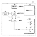
以下、本発明に係る表示装置及びバックライトの駆動方法を実施の形態を示す図面に基づいて説明する。図1は本実施の形態の表示装置100の構成の一例を示すブロック図である。表示装置100は、表示パネルとしての液晶表示パネル10、液晶表示パネル10の背面に配置されたバックライト20、ブライトネス設定部30、画像処理部40、PWM信号生成部50、ドライバ60などを備える。なお、表示パネルは液晶に限定されるものではなく、他の遮光部材から構成された表示パネルでもよい。
Hereinafter, a display device and a backlight driving method according to the present invention will be described with reference to the drawings illustrating embodiments. FIG. 1 is a block diagram showing an example of the configuration of the
バックライト20は、直列接続した複数のLED21、各LED21に流れる電流(駆動電流)をオン/オフするスイッチング素子としてのトランジスタ22、トランジスタ22のベースに流れる電流を適切な値に制限するためのバイアス抵抗23などを備える。なお、図1の例では、複数のLED21を直列接続した構成を示すが、LED21の個数、接続形態は図1の例に限定されるものではない。
The
画像処理部40は、例えば外部の装置から取得した画像データ、あるいは不図示の記憶装置に記憶した画像データを読み出し、1フレーム毎の画像信号を液晶表示パネル10へ出力する。本実施の形態では、画像信号は映像信号とも称する。1フレーム期間は、液晶表示パネル10が画面に表示する1フレームの画像を書き換える書き換え周期であり、液晶表示パネル10の垂直同期信号の間隔である。1フレーム期間、すなわち垂直同期信号の周期は、例えば、120Hzであるが、これに限定されるものではなく、60Hz、240Hzなどであってもよい。
The
液晶表示パネル10は、垂直同期信号をPWM信号生成部50へ出力する。なお、図1の例では、液晶表示パネル10が垂直同期信号を出力する構成を例示しているが、これに限定されるものではなく、液晶表示パネル10の表示制御を行う表示制御部(不図示)が液晶表示パネル10と別個に存在する場合には、当該表示制御部が垂直同期信号を出力するようにしてもよい。
The liquid
図2は本実施の形態の表示装置100のフレームの書き換えの一例を示す説明図である。図2の上段は、フレーム(1フレームの画像)の書き換えの様子を示し、下段は、垂直同期信号のタイミングを示す。図2に示すように、垂直同期信号は、所定の書き換え周期Tで繰り返し出力される。本実施の形態では、書き換え周期Tは、120Hzであり、1フレームの期間は、約8.3msである。なお、書き換え周期Tは、120Hzに限定されるものではなく、60Hz、240Hzなどであってもよい。
FIG. 2 is an explanatory diagram showing an example of frame rewriting of the
液晶表示パネル10は、書き換え周期Tの間に同じ画像のフレームを2回書込む。例えば、便宜上、図2に示すように、時系列的にフレーム1〜6があり、フレーム1が画像Aであるとする。液晶表示パネル10は、フレーム2、3とで同じ画像Bを書込む。
The liquid
フレーム2では、フレーム1で書込んだ画像Aが残存しているので、画像Aから画像Bに徐々に書き換えることになる。フレーム2の終了時点では、画像Bが書込まれている。そして、フレーム3では、再度画像Bを書込むので、画像Bだけが表示される。実際には、画像Bを画像Bで書き換える処理が行われる。
In
なお、フレーム3の画像Bの書込みが終了した時点と、垂直同期信号との間には、若干の時間差(時間のずれ)ΔTが存在する。この時間差ΔTは、内部処理による時間差であり、例えば、1ms程度である。また、垂直同期信号の周期Tは、120Hzであり、垂直同期信号間の時間は、約8.3msである。なお、液晶表示パネル10の内部では、2倍の周期である240Hzで書込みが実施されている。
Note that there is a slight time difference (time shift) ΔT between the time when the writing of the image B of the
同様に、フレーム4では、フレーム3で書込んだ画像Bが残存しているので、画像Bから画像Cに徐々に書き換えることになる。フレーム4の終了時点では、画像Cが書込まれている。そして、フレーム5では、再度画像Cを書込むので、画像Cだけが表示される。実際には、画像Cを画像Cで書き換える処理が行われる。
Similarly, since the image B written in the
また、フレーム6では、フレーム5で書込んだ画像Cが残存しているので、画像Cから画像Dに徐々に書き換えることになる。以下、同様である。
In
ブライトネス設定部30は、液晶表示パネル10の輝度を調整する機能を有し、例えば、ブライトネス調整値が0〜100%の範囲で液晶表示パネル10の画面の輝度を設定することができる。ブライトネス設定部30は、表示装置100に設けたボリューム(不図示)でもよく、あるいは画面に表示する設定画面でもよい。ユーザーによらず、表示装置100が自発的にこれを設定するようにしてもよい。あるいは、USBなどの通信インターフェースを介して、表示装置100の外部のコンピュータなどの情報機器から設定するようにしてもよい。ブライトネス設定部30は、設定された調整値としてのブライトネス調整値をPWM信号生成部50へ出力する。
The
PWM信号生成部50は、駆動制御手段としての機能を有し、液晶表示パネル10の書き換え周期Tに同期して、バックライト20を駆動する駆動期間及び駆動を休止する休止期間を交互に繰り返す駆動電流の当該駆動期間の長短を制御する。なお、図1の例において、PWM1信号が駆動電流に対応する。PWM信号生成部50は、PWM1信号をドライバ60へ出力する。
The PWM
PWM1信号の周期は、液晶表示パネル10の書き換え周期Tと同期する。本実施の形態では、PWM1信号の周期は、120Hzである。PWM1信号は、PWM制御されたパルス信号であり、駆動期間(オン期間)は、パルス信号のパルス幅に相当し、休止期間(オフ期間)は、隣り合うパルス信号の間の期間である。すなわち、駆動期間においては、バックライト20を点灯させ、休止期間においては、バックライト20を消灯させる。駆動期間の長短は、PWM1信号のパルス幅の長短であり、駆動期間を長短にすることは、PWM制御のデューティ比を大小とすることである。PWM1信号の駆動期間を長く(休止期間を短く)する(すなわち、PWM1信号のデューティ比を大きく)ことにより、バックライト20が発する光量が増加し、液晶表示パネル10の輝度は高くなる。
The period of the PWM1 signal is synchronized with the rewrite period T of the liquid
PWM信号生成部50は、駆動制御手段としての機能を有し、駆動期間(オン期間)にバックライト20へ供給する駆動電流の多少を制御する。例えば、PWM1信号を所定のデューティ比とした場合、駆動期間での駆動電流を多くする(増加させる)ことにより、バックライト20が発する光量が増加し、液晶表示パネル10の輝度を高くすることができる。また、駆動期間での駆動電流を少なくする(減少させる)ことにより、バックライト20が発する光量が減少し、液晶表示パネル10の輝度を低くすることができる。
The PWM
より具体的には、PWM信号生成部50は、駆動電流を増減させるためにPWM0信号をドライバ60へ出力する。PWM0信号は、例えば、周期が18kHz程度のPWM制御されたパルス信号であり、バックライト20へ供給する駆動電流を増加させる場合には、PWM0信号のデューティ比を大きくし、駆動電流を減少させる場合には、PWM0信号のデューティ比を小さくする。
More specifically, the PWM
ドライバ60は、いわゆる信号変換機能を有する。ドライバ60は、PWM信号生成部50が出力したPWM1信号をそのまま、あるいは増幅又はインピダンス変換等を行ってバックライト20のトランジスタ22のベースへ出力する。かかる構成により、PWM1信号の駆動期間(オン期間)では、トランジスタ22がオンし、LED21に電流(駆動電流)が流れ、バックライト20は点灯する。一方、PWM1信号の休止期間(オフ期間)では、トランジスタ22がオフとなり、LED21に電流(駆動電流)が流れないので、バックライト20は消灯する。
The
また、ドライバ60は、ローパスフィルタ、電源部などを備え、PWM信号生成部50が出力したPWM0信号をローパスフィルタで直流電圧に変換し、変換した直流電圧の高低に応じて、駆動電流の多少を制御してバックライト20へ出力する。すなわち、PWM0信号のデューティ比が大きいほど、ローパスフィルタで変換された直流電圧が高くなり、ドライバ60がバックライト20へ供給する駆動電流が多くなる。なお、後述するように、バックライトの光量は駆動電流の積分値で決まるから、必ずしも直流電圧にする必要はなく、PWM信号のままバックライト20を駆動するようにしてもよい。
The
図3は本実施の形態の表示装置100による駆動期間制御の一例を示すタイムチャートである。駆動期間制御とは、PWM1信号のデューティ比を変化させてバックライト20を駆動する制御である。図3Aは低輝度領域の場合を示し、図3Bは高輝度領域の場合を示す。低輝度領域とは、ブライトネス調整値が所定値より低い範囲をいい、高輝度領域とは、ブライトネス調整値が所定値より高い範囲をいう。所定値は、例えば、バックライト20へ供給する駆動電流の上限値に対応させて設定することができる。すなわち、低輝度領域とは、バックライト20へ供給する駆動電流が上限値よりも少ない領域であり、高輝度領域とは、バックライト20へ供給する駆動電流が上限値に達した領域である。
FIG. 3 is a time chart showing an example of drive period control by the
PWM1信号は、垂直同期信号の周期Tに同期している。PWM1信号を垂直同期信号と同期させる位相制御ポイントは、垂直同期信号から時間差ΔT(例えば、1ms程度)だけ早い時点であり、この時間差ΔTを維持したままデューティ比を変化させて位相制御(同期制御)を行う。 The PWM1 signal is synchronized with the period T of the vertical synchronization signal. The phase control point for synchronizing the PWM1 signal with the vertical synchronization signal is a time point earlier than the vertical synchronization signal by a time difference ΔT (for example, about 1 ms), and the phase control (synchronization control) is performed by changing the duty ratio while maintaining the time difference ΔT. )I do.
図3Aに示すように、PWM1信号の駆動期間(パルス幅、オン期間)をT1とすると、デューティ比α1は、α1=T1/Tで表すことができる。また、図3Bに示すように、高輝度領域では、PWM1信号の駆動期間(パルス幅、オン期間)をT2とすると、デューティ比α2は、α2=T2/T(α2>α1)で表すことができる。 As shown in FIG. 3A, when the drive period (pulse width, ON period) of the PWM1 signal is T1, the duty ratio α1 can be expressed as α1 = T1 / T. Further, as shown in FIG. 3B, in the high luminance region, when the drive period (pulse width, ON period) of the PWM1 signal is T2, the duty ratio α2 can be expressed as α2 = T2 / T (α2> α1). it can.
図3A、図3Bに示すように、PWM1信号は、位相制御ポイントを維持した状態でデューティ比を変化させる。そして、PWM1信号の駆動期間(オン期間)では、図2で示したように、フレームの画像は、同じ画像を2回目に書き換えるタイミングとなるので、異なる画像が1フレーム中に混在することがない。また、PWM1信号の休止期間(オフ期間)では、異なる画像が1フレーム中で混在する。逆に言えば、異なる画像が1フレーム中で混在するフレームは、PWM1信号の休止期間(オフ期間)中にあるので、バックライト20は消灯期間となり、異なる画像が混在する状態が視認されることがない。そして、バックライト20の点灯期間では、異なる画像が混在していないので、映像の重なり、ぼけ等がなくなり、動画の視認性を向上させることができる。前述では時間差ΔTを維持して駆動期間の同期制御を行うとしたが、これに限定されず、異なる画像が混在しない2回目の書き換え期間内であればよい。例えば、2回目の書き換え開始時点を基準に位相制御してもよいし、2回目の書き換え期間内にランダムあるいは規則的に位相を移動させるようにしてもよい。
As shown in FIGS. 3A and 3B, the PWM1 signal changes the duty ratio while maintaining the phase control point. In the drive period (ON period) of the PWM1 signal, as shown in FIG. 2, the image of the frame has a timing for rewriting the same image for the second time, so that different images are not mixed in one frame. . Further, different images are mixed in one frame in the pause period (off period) of the PWM1 signal. In other words, since a frame in which different images are mixed in one frame is in the pause period (off period) of the PWM1 signal, the
図4は本実施の形態の表示装置100による駆動電流制御の一例を示すタイムチャートである。駆動電流制御とは、PWM0信号のデューティ比を変化させてバックライト20へ供給する駆動電流を増減する制御である。図4Aは、PWM1信号を示し、図4Bは、駆動電流が比較的少ない場合を示し、図4Cは、駆動電流が比較的多い場合を示す。なお、図4において、電流波形は、簡便のため模式的に矩形状で示す。
FIG. 4 is a time chart showing an example of drive current control by the
図4Bに示すように、PWM1信号の駆動期間(オン期間)においてバックライト20へ供給する電流波形の波高値をI1とする。また、図4Cに示すように、PWM1信号の駆動期間(オン期間)においてバックライト20へ供給する電流波形の波高値をI2とする。電流波形の波高値を変化させることにより、駆動電流の多少を制御することができる。
As shown in FIG. 4B, the peak value of the current waveform supplied to the
輝度は、駆動のための電流波形の積分値で決まるから、駆動電流を一定の波高値に変化させるばかりでなく、駆動期間内で波高値を上下させるようにしてもよい。波高値の変化量や変化タイミングは、目視などで最適になるよう適宜設定すればよい。 Since the luminance is determined by the integrated value of the current waveform for driving, not only the driving current is changed to a constant peak value, but also the peak value may be raised or lowered within the driving period. What is necessary is just to set suitably the variation | change_quantity and change timing of a peak value so that it may become optimal visually.
次に、本実施の形態の表示装置100によるバックライト20の駆動方法について説明する。図5は本実施の形態の表示装置100によるバックライト20の駆動方法の第1例を示す説明図である。図5において、横軸はブライトネス設定部30で設定するブライトネス調整値を示す。左側の縦軸は割合(%)を示し、PWM1信号のデューティ比及びバックライト20へ供給する駆動電流の電流波形の波高値(駆動電流値)を%で示す。波高値の100%は回路的に流すことのできる上限(許容範囲)となる。また、右側の縦軸は液晶表示パネル10の輝度を示す。
Next, a method for driving the
図5に示すように、ブライトネス調整値が所定値より低い範囲(図5の例では、ブライトネス調整値が0〜B1%の範囲)では、PWM信号生成部50は、駆動期間(又は休止期間)を所定期間とする。すなわち、PWM信号生成部50は、デューティ比を所要の値(図5の例では、α1%)に固定する。なお、デューティ比は、目視により動画の視認性が最適となる値に設定され、パネルの特性や回路性能によって異なる。同時に、PWM信号生成部50は、ブライトネス調整値(図5の例では、0%以上B1%以下)に応じて、駆動電流の波高値を変化させて駆動電流を増減する(図5の例では、駆動電流値がI1〜I2%)。PWM1信号のデューティ比を所要の値に固定することにより、画面に動画を表示させた場合でも、動画の視認性を向上させ、フリッカなどの発生を抑制することができる。また、ブライトネスの高低に応じて、駆動電流を増減することにより、液晶表示パネル10の輝度を調整(調光)することができる。前述のとおり波高値にかぎらず、休止期間を利用した積分変化で駆動電流を調整してもよい。
As shown in FIG. 5, in the range where the brightness adjustment value is lower than the predetermined value (in the example of FIG. 5, the range where the brightness adjustment value is 0 to B1%), the PWM
また、ブライトネス調整値が所定値より高い範囲(図5の例では、ブライトネス調整値がB1%より大きく100%以下の範囲)では、駆動電流は上限の100%に達しているため駆動電流のみで光量を増加させることができないため、PWM信号生成部50は、駆動期間を所定期間より長くする(又は休止期間を所定期間より短くする)。すなわち、PWM信号生成部50は、PWM1信号のデューティ比を前述の所要の値(α1%)よりも大きくする。駆動期間を所定期間より長くすることにより、駆動電流を増加させることなく、駆動電流が流れる期間を長くして、バックライト20が発する光量を増加させ、液晶表示パネル10の輝度を高くすることができる。これにより、ブライトネス調整値が所定値より高い範囲で液晶表示パネル10の輝度をさらに高くすることができ、液晶表示パネル10の調光範囲を拡大することができる。
In the range where the brightness adjustment value is higher than the predetermined value (in the example of FIG. 5, the brightness adjustment value is in the range of more than B1% and 100% or less), the drive current has reached 100% of the upper limit, so only the drive current is used. Since the amount of light cannot be increased, the PWM
より具体的には、PWM信号生成部50は、ブライトネス調整値が所定値より高い範囲(図5の例では、ブライトネス調整値がB1%より大きく100%以下の範囲)では、ブライトネス調整値の高低に応じて、駆動期間を長短とする。図5の例では、ブライトネス調整値がB1%から100%に増えると、PWM1信号のデューティ比は、α1%からα2%に増加させている。
More specifically, the PWM
ブライトネス調整値が0%以上B1%の範囲において、PWM1信号のデューティ比をα1%に固定するとともに、駆動電流をI1%からI2%に増加させることにより、液晶表示パネル10の輝度は、L1[cd/m2 ]からL2[cd/m2 ]に増加する。また、ブライトネス調整値がB1〜100%の範囲において、駆動電流をI2%に固定したまま、PWM1信号のデューティ比をα1%からα2%にすることで、液晶表示パネル10の輝度は、L2[cd/m2 ]からL3[cd/m2 ]に増加する。
In the range where the brightness adjustment value is 0% or more and B1%, the duty ratio of the PWM1 signal is fixed to α1%, and the drive current is increased from I1% to I2%. cd / m 2 ] increases to L2 [cd / m 2 ]. Further, when the brightness adjustment value is in the range of B1 to 100%, the drive current is fixed at I2%, and the duty ratio of the PWM1 signal is changed from α1% to α2%, so that the luminance of the liquid
このように、PWM信号のデューティ比を固定し、駆動電流を増加させる構成の場合には、図5で例示するように、液晶表示パネル10の輝度の最大輝度は、L2[cd/m2 ]となり、それ以上の輝度は望めない。しかし、本実施の形態のように、駆動電流を100%に維持しつつ、PWM1信号のデューティ比を、ブライトネス調整値の高低に応じて長くすることにより、最大輝度をL3[cd/m2 ]まで増加させることができ、高輝度領域の調光範囲を拡大させることができる。発明者の実験によれば、本実施の形態により最大輝度を30%程度増加させることができた。
As described above, in the case of a configuration in which the duty ratio of the PWM signal is fixed and the drive current is increased, the maximum luminance of the liquid
また、図5から解るように、ブライトネス調整値が0%以上B1%以下の範囲と、ブライトネス調整値がB1%より大きく100%以下の範囲とにおいて、輝度の変化割合をリニアにすることができる。このように、ブライトネス調整値が所定値より低い範囲において、ブライトネスの高低に応じて、駆動電流を増減した場合の液晶表示パネル10の輝度の変化の割合と、ブライトネス調整値が所定値より高い範囲において、ブライトネス調整値の高低に応じて、駆動期間を長短とした場合の液晶表示パネル10の輝度の変化の割合とを同等にすることにより、ブライトネス調整値が所定値より高い範囲においても、ブライトネス調整値が所定値より低い範囲と同様(リニア)の調光を実現することができる。
Further, as can be seen from FIG. 5, the luminance change rate can be made linear in the range where the brightness adjustment value is 0% or more and B1% or less and in the range where the brightness adjustment value is greater than B1% and 100% or less. . As described above, in the range where the brightness adjustment value is lower than the predetermined value, the rate of change in the luminance of the liquid
また、PWM信号生成部50は、ブライトネス調整値がB1%より大きく100%以下の範囲では、駆動電流を一定(I2%)にする。すなわち、ブライトネス調整値が所定値より高い範囲では、ブライトネス調整値の高低に応じて、駆動電流の駆動期間を長短とするので、駆動電流を増加させることなく一定とすることができる。これにより、駆動電流が回路的な上限に達した場合であっても、液晶表示パネル10の輝度をさらに高くすることができ、液晶表示パネル10の調光範囲を拡大することができる。
Further, the PWM
また、画面の輝度を低輝度と高輝度との区分けする所定値(図5の例では、ブライトネス調整値がB1%)を、バックライト20へ供給する駆動電流の上限値に対応させて設定してある。これにより、駆動電流が上限値より少ない範囲(輝度が所定値より低い範囲)では、駆動信号の駆動期間を固定して、動画の視認性を向上し、フリッカ等の発生を抑制しつつ、駆動電流を増減することにより調光を可能とすることができる。また、駆動電流が上限値に達した範囲(輝度が所定値より高い範囲)では、駆動電流を上限値で一定とし、駆動信号の駆動期間を長くすることにより、動画の視認性を向上させつつ高輝度側での調光範囲を拡大することができる。本実施例では、ブライトネス調整値が0%以上B1%以下を低輝度、ブライトネス調整値がB1%より大きく100%以下を高輝度と区分けしたが、これに限定されず、ブライトネス調整値が0%以上B1%未満を低輝度、ブライトネス調整値がB1%以上100%以下を高輝度と区分けしてもよい。
In addition, a predetermined value (in the example of FIG. 5, the brightness adjustment value is B1%) for dividing the screen brightness into low brightness and high brightness is set in correspondence with the upper limit value of the drive current supplied to the
図6は本実施の形態の表示装置100によるバックライト20の駆動方法の第2例を示す説明図である。上述の図5の例では、調整値が所定値(ブライトネス調整値がB1%)より高い範囲では、駆動電流を一定とし、駆動期間をブライトネス調整値に応じて長短とするようにしたが、これに限定されるものではない。図6に示すように、調整値が所定値(ブライトネス調整値がB1%)より高い範囲において、駆動期間を一定(図6の例では、デューティ比がα2)とし、ブライトネス調整値に応じて駆動電流を多少するようにしてもよい(図6の例では、駆動電流をI3%〜I2%)。この場合、図5の場合と同様に、ブライトネス調整値は0%以上B1%以下の範囲では、輝度がL1からL2に増加し、ブライトネス調整値はB1%より大きく100%以下の範囲では、輝度がL2からL3に増加する。上記に限らず、ブライトネス調整値が0%以上B1%未満とブライトネス調整値がB1%以上100%以下との範囲で駆動方法をかえるようにしてもよい。
FIG. 6 is an explanatory diagram showing a second example of a method for driving the
図7は本実施の形態の表示装置100によるバックライト20の駆動方法の第3例を示す説明図である。図7の例は、駆動電流又は駆動期間のいずれか一方を一定とするのではなく、駆動電流及び駆動期間双方を変更して、所望の輝度を得るようするものである。図7に例示する第3例は、特にLED21の温度特性を考慮した駆動方法として有用である。LED21は、その周囲温度の上昇に伴い定格電流が低下することが知られている。高輝度において駆動期間を長くしていった場合、LED21の発熱量が増加し、その周囲温度が上昇する可能性がある。そこで、図7に示すように、想定される上昇温度見合った駆動電流I4に向かって電流を低下させる一方、輝度がリニアに増加するよう駆動期間をα3(>α2)に向かって長くするように駆動すればよい。
FIG. 7 is an explanatory diagram illustrating a third example of a method of driving the
上述の実施の形態において、ブライトネス調整値が0〜B1%の低輝度領域において、PWM1信号のデューティ比をα1%としたが、デューティ比はα1%に限定されるものではない。また、ブライトネス調整値がB1〜100%の高輝度領域において、PWM1信号のデューティ比をα1%〜α2%としたが、デューティ比はこれらに値に限定されるものではない。例えば、ブライトネス調整値が0〜B1%の低輝度領域において、デューティ比をα1%〜α2%とし、ブライトネス調整値がB1〜100%の高輝度領域において、デューティ比をα2%〜50%とすることもできる。デューティ比をα1%より小さくした場合には、フリッカ等のちらつきが目立つようになる。また、デューティ比が50%を超えると、異なる画像が混在するフレームの一部でバックライトが点灯することになり、動画の視認性が劣るからである。 In the above-described embodiment, the duty ratio of the PWM1 signal is α1% in the low luminance region where the brightness adjustment value is 0 to B1%, but the duty ratio is not limited to α1%. In the high luminance region where the brightness adjustment value is B1 to 100%, the duty ratio of the PWM1 signal is set to α1% to α2%. However, the duty ratio is not limited to these values. For example, in a low luminance region where the brightness adjustment value is 0 to B1%, the duty ratio is α1% to α2%, and in a high luminance region where the brightness adjustment value is B1 to 100%, the duty ratio is α2% to 50%. You can also When the duty ratio is smaller than α1%, flicker or the like flickers. Further, if the duty ratio exceeds 50%, the backlight is turned on in a part of the frame in which different images are mixed, and the visibility of the moving image is poor.
上述の実施の形態において、低輝度領域と高輝度領域とを区分けするブライトネスの所定値をB1%としたが、所定値はB1%に限定されるものではない。ブライトネスを0%から増加したときに、バックライト20を構成するLEDの順方向定格電流、ドライバ60の電源部の仕様等に応じて、駆動電流が上限値となるブライトネスの値を所定値とすることができる。
In the above-described embodiment, the predetermined value of brightness for dividing the low-luminance region and the high-luminance region is B1%. However, the predetermined value is not limited to B1%. When the brightness is increased from 0%, the brightness value at which the drive current becomes the upper limit value is set to a predetermined value in accordance with the forward rated current of the LEDs constituting the
10 液晶表示パネル
20 バックライト
30 ブライトネス設定部
40 画像処理部
50 PWM信号生成部
60 ドライバ
DESCRIPTION OF
Claims (8)
前記バックライトを駆動する駆動期間及び駆動を休止する休止期間を交互に前記所定の周期に同期して繰り返す駆動電流の該駆動期間の長短及び前記駆動期間に前記バックライトへ供給する駆動電流の多少を制御する駆動制御手段を備え、
前記書き換え手段は、前記所定の周期の間に同じ画像のフレームを2回書き込み、
前記駆動制御手段は、
異なる画像が1フレーム中で混在しない期間に前記駆動期間が含まれるようにし、かつ、異なる画像が1フレーム中で混在する期間が前記休止期間に含まれるようにし、
前記調整値が所定値より低い範囲では、前記休止期間を所定期間とし、前記調整値が前記所定値より高い範囲では、前記休止期間を前記所定期間より短くしてあり、
前記所定値を、前記バックライトへ供給する駆動電流の上限値に対応させて設定してあり、
前記調整値が前記所定値より高い範囲では、前記調整値が増加すると、前記駆動電流の積分値を増加するようにしてある
ことを特徴とする表示装置。 In a display device comprising: a display panel; a rewriting unit that rewrites an image displayed on the screen of the display panel at a predetermined period; and a backlight for the display panel that adjusts the brightness of the screen according to an arbitrary adjustment value. ,
The driving period for driving the backlight and the pause period for stopping driving are alternately repeated in synchronization with the predetermined period, and the length of the driving period and the amount of driving current supplied to the backlight during the driving period Drive control means for controlling
The rewriting means writes the same image frame twice during the predetermined period,
The drive control means includes
The drive period is included in a period in which different images are not mixed in one frame, and a period in which different images are mixed in one frame is included in the pause period.
In the range where the adjustment value is lower than a predetermined value, the pause period is set as a predetermined period, and in the range where the adjustment value is higher than the predetermined value, the pause period is shorter than the predetermined period,
The predetermined value is set in correspondence with an upper limit value of a drive current supplied to the backlight;
In the range in which the adjustment value is higher than the predetermined value, the integral value of the drive current is increased as the adjustment value increases.
前記駆動制御手段は、前記駆動電流に対応するPWM信号を前記垂直同期信号と同期させる位相制御ポイントを、前記垂直同期信号から所定の時間差だけ早い時点として、前記駆動期間及び前記休止期間を交互に前記所定の周期に同期して繰り返す前記駆動期間の長短及び前記駆動電流の多少を制御する、請求項1に記載の表示装置。 The predetermined period is a period of a vertical synchronization signal of the display panel,
The drive control means alternates the drive period and the rest period with a phase control point for synchronizing a PWM signal corresponding to the drive current with the vertical synchronization signal as a time point earlier than the vertical synchronization signal by a predetermined time difference. The display device according to claim 1, wherein the length of the driving period repeated in synchronization with the predetermined period and the amount of the driving current are controlled.
前記駆動制御手段は、前記駆動電流に対応するPWM信号を前記垂直同期信号と同期させる位相制御ポイントを、同じ画像のフレームの2回目の書き換え開始時点を基準にして定め、前記駆動期間及び前記休止期間を交互に前記所定の周期に同期して繰り返す前記駆動期間の長短及び前記駆動電流の多少を制御する、請求項1に記載の表示装置。 The predetermined period is a period of a vertical synchronization signal of the display panel,
The drive control means determines a phase control point for synchronizing a PWM signal corresponding to the drive current with the vertical synchronization signal with reference to a second rewrite start time of a frame of the same image, and the drive period and the pause The display device according to claim 1, wherein the length of the driving period and the amount of the driving current are controlled alternately and in synchronization with the predetermined period.
前記バックライトを駆動する駆動期間及び駆動を休止する休止期間を交互に前記所定の周期に同期して繰り返す駆動電流の該駆動期間の長短及び前記駆動期間に前記バックライトへ供給する駆動電流の多少を制御する制御ステップを含み、
前記表示パネルは、前記所定の周期の間に同じ画像のフレームを2回書き込み、
該制御ステップは、
異なる画像が1フレーム中で混在しない期間に前記駆動期間が含まれるようにし、かつ、異なる画像が1フレーム中で混在する期間が前記休止期間に含まれるようにし、
前記調整値が所定値より低い範囲では、前記休止期間を所定期間とし、前記調整値が所定値より高い範囲では、前記休止期間を前記所定期間より短くし、
前記所定値を、前記バックライトへ供給する駆動電流の上限値に対応させて設定してあり、
前記調整値が前記所定値より高い範囲では、前記調整値が増加すると、前記駆動電流の積分値を増加するようにしてあることを特徴とする駆動方法。 In the method of driving the backlight by a display device comprising: a display panel that rewrites an image to be displayed on a screen at a predetermined period; and a backlight for the display panel that adjusts the brightness of the screen according to an arbitrary adjustment value.
The driving period for driving the backlight and the pause period for stopping driving are alternately repeated in synchronization with the predetermined period, and the length of the driving period and the amount of driving current supplied to the backlight during the driving period Including control steps for controlling
The display panel writes the same image frame twice during the predetermined period,
The control step includes:
The drive period is included in a period in which different images are not mixed in one frame, and a period in which different images are mixed in one frame is included in the pause period.
In the range where the adjustment value is lower than the predetermined value, the pause period is set as the predetermined period, and in the range where the adjustment value is higher than the predetermined value, the pause period is shorter than the predetermined period,
The predetermined value is set in correspondence with an upper limit value of a drive current supplied to the backlight;
In the range where the adjustment value is higher than the predetermined value, when the adjustment value increases, the integral value of the drive current is increased.
Priority Applications (7)
| Application Number | Priority Date | Filing Date | Title |
|---|---|---|---|
| JP2013145521A JP6369929B2 (en) | 2013-07-11 | 2013-07-11 | Display device and driving method of backlight |
| EP14823497.4A EP3021312B1 (en) | 2013-07-11 | 2014-07-11 | Display device and drive method for backlight |
| CN201480039585.6A CN105556586A (en) | 2013-07-11 | 2014-07-11 | Display device and drive method for backlight |
| PCT/JP2014/068534 WO2015005465A1 (en) | 2013-07-11 | 2014-07-11 | Display device and drive method for backlight |
| AU2014288113A AU2014288113B2 (en) | 2013-07-11 | 2014-07-11 | Display device and drive method for backlight |
| RU2016103757A RU2627641C1 (en) | 2013-07-11 | 2014-07-11 | Display device and method for backlight control |
| US14/989,800 US9978316B2 (en) | 2013-07-11 | 2016-01-07 | Display apparatus and backlight drive method |
Applications Claiming Priority (1)
| Application Number | Priority Date | Filing Date | Title |
|---|---|---|---|
| JP2013145521A JP6369929B2 (en) | 2013-07-11 | 2013-07-11 | Display device and driving method of backlight |
Publications (3)
| Publication Number | Publication Date |
|---|---|
| JP2015018111A JP2015018111A (en) | 2015-01-29 |
| JP2015018111A5 JP2015018111A5 (en) | 2016-06-30 |
| JP6369929B2 true JP6369929B2 (en) | 2018-08-08 |
Family
ID=52280142
Family Applications (1)
| Application Number | Title | Priority Date | Filing Date |
|---|---|---|---|
| JP2013145521A Active JP6369929B2 (en) | 2013-07-11 | 2013-07-11 | Display device and driving method of backlight |
Country Status (7)
| Country | Link |
|---|---|
| US (1) | US9978316B2 (en) |
| EP (1) | EP3021312B1 (en) |
| JP (1) | JP6369929B2 (en) |
| CN (1) | CN105556586A (en) |
| AU (1) | AU2014288113B2 (en) |
| RU (1) | RU2627641C1 (en) |
| WO (1) | WO2015005465A1 (en) |
Families Citing this family (10)
| Publication number | Priority date | Publication date | Assignee | Title |
|---|---|---|---|---|
| CN104505055B (en) * | 2014-12-31 | 2017-02-22 | 深圳创维-Rgb电子有限公司 | Method and device for adjusting backlight brightness |
| JP6769154B2 (en) * | 2016-07-27 | 2020-10-14 | 日本精機株式会社 | Head-up display |
| JP2018060007A (en) * | 2016-10-04 | 2018-04-12 | 株式会社ジャパンディスプレイ | Display device and display control method |
| US10986707B2 (en) * | 2017-08-09 | 2021-04-20 | Innolux Corporation | Display device |
| CN107230456A (en) * | 2017-08-10 | 2017-10-03 | 京东方科技集团股份有限公司 | A kind of display device and brightness adjusting method |
| CN110189709B (en) * | 2018-02-23 | 2020-12-29 | 京东方科技集团股份有限公司 | Control circuit, backlight driving device and display device |
| CN108962150B (en) * | 2018-06-13 | 2020-06-09 | 深圳创维-Rgb电子有限公司 | Image quality optimization method, device and equipment based on regional dimming and storage medium |
| WO2020199007A1 (en) * | 2019-03-29 | 2020-10-08 | 京东方科技集团股份有限公司 | Display drive method, drive apparatus and display apparatus |
| CN112242125B (en) * | 2019-07-19 | 2023-08-18 | 深圳光峰科技股份有限公司 | Display apparatus |
| TWI735333B (en) * | 2020-09-09 | 2021-08-01 | 友達光電股份有限公司 | Display device and driving method thereof |
Family Cites Families (21)
| Publication number | Priority date | Publication date | Assignee | Title |
|---|---|---|---|---|
| JPH05303078A (en) | 1992-04-10 | 1993-11-16 | Oputonikusu Kk | Liquid crystal display device |
| JP2002056996A (en) * | 2000-08-11 | 2002-02-22 | Nippon Avionics Co Ltd | Liquid crystal back light control method |
| CN1993724B (en) * | 2004-07-29 | 2010-10-27 | 皇家飞利浦电子股份有限公司 | Driving a display with a polarity inversion pattern |
| US8593382B2 (en) * | 2006-09-26 | 2013-11-26 | Nlt Technologies, Ltd. | Liquid crystal display device |
| JP2008102442A (en) * | 2006-10-20 | 2008-05-01 | Olympus Corp | Image projector |
| WO2008062578A1 (en) * | 2006-11-24 | 2008-05-29 | Sharp Kabushiki Kaisha | Image display apparatus |
| EP2018052B1 (en) * | 2007-02-20 | 2014-12-10 | Sony Corporation | Image display device |
| JP4450019B2 (en) * | 2007-07-03 | 2010-04-14 | ソニー株式会社 | Control device and control method, and planar light source device and planar light source device control method |
| JP4858394B2 (en) | 2007-10-10 | 2012-01-18 | マツダ株式会社 | Exhaust gas component purification catalyst material and particulate filter with the catalyst material |
| US8345038B2 (en) * | 2007-10-30 | 2013-01-01 | Sharp Laboratories Of America, Inc. | Methods and systems for backlight modulation and brightness preservation |
| US8400391B2 (en) * | 2008-01-10 | 2013-03-19 | Honeywell International Inc. | Method and system for improving dimming performance in a field sequential color display device |
| KR101362771B1 (en) * | 2008-09-17 | 2014-02-14 | 삼성전자주식회사 | Apparatus and method for displaying stereoscopic image |
| JP5208035B2 (en) * | 2009-04-02 | 2013-06-12 | 三菱電機株式会社 | Liquid crystal display |
| JP4686644B2 (en) * | 2009-07-07 | 2011-05-25 | シャープ株式会社 | Liquid crystal display |
| KR101366964B1 (en) * | 2009-12-30 | 2014-02-24 | 엘지디스플레이 주식회사 | Liquid crystal display |
| JP5199327B2 (en) * | 2010-05-28 | 2013-05-15 | シャープ株式会社 | Display device and display method |
| CN102890917B (en) * | 2011-07-20 | 2015-09-02 | 乐金显示有限公司 | Backlight drive device and driving method, liquid crystal display and driving method thereof |
| KR101891971B1 (en) * | 2011-09-06 | 2018-10-01 | 삼성디스플레이 주식회사 | Display apparatus and driving method thereof |
| CN102708804B (en) * | 2011-10-21 | 2014-12-24 | 京东方科技集团股份有限公司 | Backlight dimming method and backlight driving circuit |
| KR101850817B1 (en) * | 2011-11-17 | 2018-04-23 | 삼성전자주식회사 | The method and apparatus for auto installing applications into different terminal |
| JP2014191111A (en) * | 2013-03-26 | 2014-10-06 | Funai Electric Co Ltd | Backlight driving circuit |
-
2013
- 2013-07-11 JP JP2013145521A patent/JP6369929B2/en active Active
-
2014
- 2014-07-11 CN CN201480039585.6A patent/CN105556586A/en active Pending
- 2014-07-11 RU RU2016103757A patent/RU2627641C1/en not_active IP Right Cessation
- 2014-07-11 WO PCT/JP2014/068534 patent/WO2015005465A1/en active Application Filing
- 2014-07-11 AU AU2014288113A patent/AU2014288113B2/en not_active Ceased
- 2014-07-11 EP EP14823497.4A patent/EP3021312B1/en active Active
-
2016
- 2016-01-07 US US14/989,800 patent/US9978316B2/en active Active
Also Published As
| Publication number | Publication date |
|---|---|
| RU2627641C1 (en) | 2017-08-10 |
| WO2015005465A1 (en) | 2015-01-15 |
| AU2014288113A1 (en) | 2016-02-11 |
| US20160117999A1 (en) | 2016-04-28 |
| JP2015018111A (en) | 2015-01-29 |
| EP3021312B1 (en) | 2023-04-05 |
| AU2014288113B2 (en) | 2016-10-20 |
| US9978316B2 (en) | 2018-05-22 |
| EP3021312A4 (en) | 2017-02-08 |
| EP3021312A1 (en) | 2016-05-18 |
| CN105556586A (en) | 2016-05-04 |
Similar Documents
| Publication | Publication Date | Title |
|---|---|---|
| JP6369929B2 (en) | Display device and driving method of backlight | |
| JP6207980B2 (en) | Display device and display method | |
| JP2016197507A (en) | Display device | |
| TWI475553B (en) | Backlight control module and backlight control method | |
| JP2014191111A (en) | Backlight driving circuit | |
| JP2007241286A (en) | Method and circuit for synchronous operation of display backlighting | |
| JP2015018111A5 (en) | ||
| US10665177B2 (en) | Circuit arrangement for controlling backlight source and operation method thereof | |
| JP6128741B2 (en) | Backlight device, control method for backlight device, and display device | |
| TWI441142B (en) | Liquid crystal display device capable of reducing ghost images and related method thereof | |
| JP2018105979A (en) | Illumination device, control method of the same, program thereof, and image display device | |
| JP2012519885A (en) | For example, anti-blurring (ANTI-BLUR) device for backlight of liquid crystal display | |
| JP6080430B2 (en) | LIGHTING DEVICE, ITS CONTROL METHOD, AND BACKLIGHT DEVICE | |
| JP6456197B2 (en) | Image display system and image display method | |
| JP6508244B2 (en) | Display device | |
| CN111540316B (en) | Circuit device for controlling backlight source and operation method thereof | |
| JP2019101368A (en) | Display device and method for controlling display device | |
| KR102115463B1 (en) | Liquid Crystal Display Device And Driving Method Thereof | |
| WO2014132422A1 (en) | Image display device and automatic power supply control method | |
| JP2010245942A (en) | Duty ratio control circuit, and method and program for controlling the same | |
| JP2015049436A (en) | Display device | |
| CN112530356B (en) | Driving method of display device | |
| JP2021162686A (en) | Video display device | |
| JP2012013787A (en) | Liquid crystal display device | |
| JP2012145778A (en) | Liquid crystal display device, liquid crystal television device provided with the same, and drive method for liquid crystal display device |
Legal Events
| Date | Code | Title | Description |
|---|---|---|---|
| A521 | Request for written amendment filed |
Free format text: JAPANESE INTERMEDIATE CODE: A523 Effective date: 20160512 |
|
| A621 | Written request for application examination |
Free format text: JAPANESE INTERMEDIATE CODE: A621 Effective date: 20160512 |
|
| A131 | Notification of reasons for refusal |
Free format text: JAPANESE INTERMEDIATE CODE: A131 Effective date: 20170425 |
|
| A521 | Request for written amendment filed |
Free format text: JAPANESE INTERMEDIATE CODE: A523 Effective date: 20170609 |
|
| A02 | Decision of refusal |
Free format text: JAPANESE INTERMEDIATE CODE: A02 Effective date: 20170704 |
|
| A521 | Request for written amendment filed |
Free format text: JAPANESE INTERMEDIATE CODE: A523 Effective date: 20170929 |
|
| RD05 | Notification of revocation of power of attorney |
Free format text: JAPANESE INTERMEDIATE CODE: A7425 Effective date: 20170929 |
|
| A911 | Transfer to examiner for re-examination before appeal (zenchi) |
Free format text: JAPANESE INTERMEDIATE CODE: A911 Effective date: 20171010 |
|
| A912 | Re-examination (zenchi) completed and case transferred to appeal board |
Free format text: JAPANESE INTERMEDIATE CODE: A912 Effective date: 20171102 |
|
| A61 | First payment of annual fees (during grant procedure) |
Free format text: JAPANESE INTERMEDIATE CODE: A61 Effective date: 20180706 |
|
| R150 | Certificate of patent or registration of utility model |
Ref document number: 6369929 Country of ref document: JP Free format text: JAPANESE INTERMEDIATE CODE: R150 |
|
| R250 | Receipt of annual fees |
Free format text: JAPANESE INTERMEDIATE CODE: R250 |
|
| R250 | Receipt of annual fees |
Free format text: JAPANESE INTERMEDIATE CODE: R250 |
|
| R250 | Receipt of annual fees |
Free format text: JAPANESE INTERMEDIATE CODE: R250 |