KR20090091295A - Vibratory gyroscope with parasitic mode damping - Google Patents
Vibratory gyroscope with parasitic mode damping Download PDFInfo
- Publication number
- KR20090091295A KR20090091295A KR1020097010024A KR20097010024A KR20090091295A KR 20090091295 A KR20090091295 A KR 20090091295A KR 1020097010024 A KR1020097010024 A KR 1020097010024A KR 20097010024 A KR20097010024 A KR 20097010024A KR 20090091295 A KR20090091295 A KR 20090091295A
- Authority
- KR
- South Korea
- Prior art keywords
- resonator
- sensing
- electrodes
- planar resonator
- planar
- Prior art date
Links
- 230000003071 parasitic effect Effects 0.000 title claims abstract description 70
- 238000013016 damping Methods 0.000 title abstract 3
- 238000000034 method Methods 0.000 claims description 29
- 239000003990 capacitor Substances 0.000 claims description 2
- 230000033001 locomotion Effects 0.000 description 17
- XUIMIQQOPSSXEZ-UHFFFAOYSA-N Silicon Chemical compound [Si] XUIMIQQOPSSXEZ-UHFFFAOYSA-N 0.000 description 14
- 229910052710 silicon Inorganic materials 0.000 description 13
- 239000010703 silicon Substances 0.000 description 13
- 230000005284 excitation Effects 0.000 description 9
- 238000002955 isolation Methods 0.000 description 7
- 230000002238 attenuated effect Effects 0.000 description 6
- 238000004519 manufacturing process Methods 0.000 description 6
- 230000010355 oscillation Effects 0.000 description 6
- 230000001133 acceleration Effects 0.000 description 4
- 239000000872 buffer Substances 0.000 description 4
- 238000010586 diagram Methods 0.000 description 4
- 238000003754 machining Methods 0.000 description 4
- VYPSYNLAJGMNEJ-UHFFFAOYSA-N silicon dioxide Inorganic materials O=[Si]=O VYPSYNLAJGMNEJ-UHFFFAOYSA-N 0.000 description 4
- 239000007787 solid Substances 0.000 description 4
- 235000012431 wafers Nutrition 0.000 description 4
- 230000008859 change Effects 0.000 description 3
- 239000002131 composite material Substances 0.000 description 3
- 238000001514 detection method Methods 0.000 description 3
- 238000005259 measurement Methods 0.000 description 3
- 230000004044 response Effects 0.000 description 3
- 238000004458 analytical method Methods 0.000 description 2
- 230000007423 decrease Effects 0.000 description 2
- 230000000694 effects Effects 0.000 description 2
- 230000008569 process Effects 0.000 description 2
- 239000010453 quartz Substances 0.000 description 2
- 238000009987 spinning Methods 0.000 description 2
- 230000009471 action Effects 0.000 description 1
- 238000005452 bending Methods 0.000 description 1
- 230000005540 biological transmission Effects 0.000 description 1
- 230000008878 coupling Effects 0.000 description 1
- 238000010168 coupling process Methods 0.000 description 1
- 238000005859 coupling reaction Methods 0.000 description 1
- 239000006185 dispersion Substances 0.000 description 1
- 238000005516 engineering process Methods 0.000 description 1
- 238000005530 etching Methods 0.000 description 1
- 230000002349 favourable effect Effects 0.000 description 1
- 239000000835 fiber Substances 0.000 description 1
- 238000001914 filtration Methods 0.000 description 1
- 230000010354 integration Effects 0.000 description 1
- 230000003993 interaction Effects 0.000 description 1
- 239000000463 material Substances 0.000 description 1
- 230000013011 mating Effects 0.000 description 1
- 238000012986 modification Methods 0.000 description 1
- 230000004048 modification Effects 0.000 description 1
- 230000003287 optical effect Effects 0.000 description 1
- 238000005457 optimization Methods 0.000 description 1
- 238000005192 partition Methods 0.000 description 1
- 238000000206 photolithography Methods 0.000 description 1
- 239000000377 silicon dioxide Substances 0.000 description 1
- 239000000725 suspension Substances 0.000 description 1
- 238000009966 trimming Methods 0.000 description 1
- 230000010356 wave oscillation Effects 0.000 description 1
Images


Classifications
-
- G—PHYSICS
- G01—MEASURING; TESTING
- G01C—MEASURING DISTANCES, LEVELS OR BEARINGS; SURVEYING; NAVIGATION; GYROSCOPIC INSTRUMENTS; PHOTOGRAMMETRY OR VIDEOGRAMMETRY
- G01C19/00—Gyroscopes; Turn-sensitive devices using vibrating masses; Turn-sensitive devices without moving masses; Measuring angular rate using gyroscopic effects
- G01C19/56—Turn-sensitive devices using vibrating masses, e.g. vibratory angular rate sensors based on Coriolis forces
- G01C19/567—Turn-sensitive devices using vibrating masses, e.g. vibratory angular rate sensors based on Coriolis forces using the phase shift of a vibration node or antinode
- G01C19/5677—Turn-sensitive devices using vibrating masses, e.g. vibratory angular rate sensors based on Coriolis forces using the phase shift of a vibration node or antinode of essentially two-dimensional vibrators, e.g. ring-shaped vibrators
- G01C19/5684—Turn-sensitive devices using vibrating masses, e.g. vibratory angular rate sensors based on Coriolis forces using the phase shift of a vibration node or antinode of essentially two-dimensional vibrators, e.g. ring-shaped vibrators the devices involving a micromechanical structure
-
- G01P9/04—
Landscapes
- Physics & Mathematics (AREA)
- Engineering & Computer Science (AREA)
- General Physics & Mathematics (AREA)
- Radar, Positioning & Navigation (AREA)
- Remote Sensing (AREA)
- Gyroscopes (AREA)
Abstract
Description
본 발명은 자이로스코프에 관한 것으로, 특히 기생모드 감쇠를 갖춘 진동식 자이로스코프에 관한 것이다.TECHNICAL FIELD The present invention relates to gyroscopes and, more particularly, to vibratory gyroscopes with parasitic mode attenuation.
기계식 자이로스코프(mechanical gyroscope)는 내부적으로 이동하는 프루프 질량체(proof mass)의 감지된 관성 반응에 기초해서 이동 플랫폼의 방향을 정하기 위해 사용된다. 전형적인 전자기계식 자이로스코프는 지지식 프루프 질량체(suspend proof mass), 자이로스코프 케이스, 픽오프(pickoff), 토커(torquer) 및 독출 전자기기(readout electronics)를 구비한다. 관성 프루프 질량체는 자이로스코프 케이스로부터 내부적으로 지지되고, 자이로스코프 케이스는 플랫폼에 단단하게 장착되어 플랫폼의 관성 이동을 전달하지만 그렇지 않은 경우는 프루프 질량체를 외란으로부터 격리한다. 프루프 질량체의 내부 이동을 감지하는 픽오프, 이 이동을 유지 또는 조절하는 토커, 및 프루프 질량체에 근접하지 않으면 안되는 독출 전자기기는, 플랫폼 전자기기 및 전원공급장치에 전기적인 관통형 접 속(feedthrough connection)을 제공하는 케이스에 내부적으로 장착되어 있다. 또한, 케이스는 자이로스코프를 이동체 플랫폼(vehicle platform)에 부착 및 정합시키기 위한 표준 기계 인터페이스도 제공한다. 각종 형태에 있어서, 자이로스코프는 항공기 및 우주선과 같은 이동체용의 임계 센서로서 종종 이용된다. 항법(navigation) 또는 자유 물체(free object)의 방향을 자율적으로 정하는 것이 필요한 경우는 언제든지 자이로스코프가 일반적으로 유용하다.A mechanical gyroscope is used to orient the moving platform based on the sensed inertial response of the proof mass moving internally. Typical electromechanical gyroscopes include a supported proof mass, a gyroscope case, a pickoff, a torquer, and readout electronics. The inertial proof mass is supported internally from the gyroscope case, and the gyroscope case is firmly mounted to the platform to transmit the inertial movement of the platform, but otherwise isolates the proof mass from disturbances. Pickoffs that sense internal movement of the proof mass, talkers that maintain or control this movement, and readout electronics that must be close to the proof mass, are electrically connected through the platform electronics and power supply. It is mounted internally in the case providing The case also provides a standard mechanical interface for attaching and mating the gyroscope to a vehicle platform. In various forms, gyroscopes are often used as threshold sensors for moving objects such as aircraft and spacecraft. Gyroscopes are generally useful whenever it is necessary to autonomously orientate navigation or free objects.
비교적 큰 스피닝 질량체(spinning mass)을 이용하는 보다 오래된 통상의 기계식 자이로스코프는, 현재의 기준으로는 아주 무거운 기구였다. 다수의 최신 기술에 의해, 레이저 자이로스코프 및 광섬유 자이로스코프 등과 같은 광학식 자이로스코프뿐만 아니라 기계식 진동식 자이로스코프를 포함하는 새로운 형태의 자이로스코프가 생겨나고 있다.Older conventional mechanical gyroscopes that use relatively large spinning masses were, by current standards, very heavy instruments. Many of the latest technologies are creating new types of gyroscopes, including mechanical gyroscopes as well as optical gyroscopes such as laser gyroscopes and fiber optic gyroscopes.
우주선은 일반적으로 자세 제어(attitude control)를 보충하기 위해 관성속도(inertial rate) 감지기기에 의존하고 있다. 현재, 이것은 고가의 통상의 스피닝 질량체 자이로(예컨대, 키어포트(Kearfott) 관성기준장치(inertial reference unit: IRU)) 또는 통상적으로 기계화된 진동식 자이로스코프(예컨대, 리톤 반구상(Litton hemispherical) 공진기 자이로스코프 관성기준장치)에 의해 종종 수행된다. 그렇지만, 이들 양자 모두 매우 고가이며 크고 또한 무겁다.Spacecraft generally rely on inertial rate detectors to compensate for attitude control. Currently, this is an expensive conventional spinning mass gyro (e.g., Kearfott inertial reference unit (IRU)) or a conventional mechanized vibratory gyroscope (e.g., Liton hemispherical resonator gyroscopes). Often by an inertial reference device). However, both of these are very expensive, large and heavy.
더욱이, 몇몇 종래의 대칭형 진동식 자이로스코프도 제작되었지만, 그들의 진동 운동량(vibratory momentum)은 케이스를 통해 이동체 플랫폼으로 직접 전송된다. 이러한 전송 또는 결합은, 관성속도 입력과 구별가능하지 않은 외란 및 에너 지 손실을 수용할 수 있고, 이로써 감지 에러 및 드리프트로 이어지게 된다. 이러한 진동식 자이로스코프의 일례는, 네 잎 클로버모양의 대칭형 진동식 자이로스코프 설계에 대해 기재하고 있는 탕(Tang) 등에 의한 미국 특허 제5,894,090에서 발견할 수 있다. 다른 평면 동조 포크(planar tuning fork) 자이로스코프는 베이스플레이트(baseplate: 기저판)로부터의 진동의 격리를 어느 정도 얻을 수 있지만, 이들 자이로스코프는 동조된 조작에 바람직한 진동 대칭을 필요로 한다.Moreover, some conventional symmetric vibratory gyroscopes have also been made, but their vibratory momentum is transmitted directly through the case to the mobile platform. This transmission or coupling can accommodate disturbances and energy losses that are indistinguishable from the inertial velocity input, leading to detection errors and drift. An example of such a vibratory gyroscope can be found in US Pat. No. 5,894,090 to Tang et al., Which describes a four-leaf clover-shaped symmetric vibratory gyroscope design. Other planar tuning fork gyroscopes can achieve some isolation of vibrations from the baseplate, but these gyroscopes require vibration symmetry that is desirable for tuned operation.
더욱이, 반구상 공진기 자이로스코프 및 진동하는 박형 링 자이로스코프 등과 같은 쉘 모드(shell mode) 자이로스코프는, 일부 소망하는 격리 및 진동 대칭 속성을 갖는 것이 알려져 있다. 그렇지만, 이들 설계는 얇은 평면 실리콘 미세제작에는 적합하지 않거나 미세제작에 상당한 제한을 갖는다. 반구상 공진기는 반구체의 광대한 원통 측면(extensive cylindrical side)을 고감도 정전 센서(sensitive electrostatic sensor) 및 유효 동작기(effective actuator)용으로 사용한다. 그렇지만, 그 높은 애스펙트비(aspect ratio: 종횡비) 및 3차원 만곡 외형(curved geometry)은 저가의 얇은 평면 실리콘 미세제작에는 적당하지 않다. 박형 링 자이로스코프(예컨대, 미국 특허 제6,282,958호)는 평면 실리콘 미세제작에 적합하지만, 장치의 광대한 평면 영역을 이용하는 정전 센서 및 동작기를 필요로 한다. 더욱이, 이 자이로스코프용의 케이스는 공진기 프루프 질량체와 같은 재료의 것이 아니므로, 공진기 프루프 질량체에 대한 픽오프 및 토커의 정렬이 온도와 함께 변화하고, 결과적으로 자이로스코프 드리프트를 일으킨다.Moreover, shell mode gyroscopes, such as hemispherical resonator gyroscopes and oscillating thin ring gyroscopes, are known to have some desired isolation and vibration symmetry properties. However, these designs are not suitable for thin planar silicon microfabrication or have significant limitations in microfabrication. Hemispherical resonators use the vastly cylindrical side of the hemisphere for sensitive electrostatic sensors and effective actuators. However, its high aspect ratio and three-dimensional curved geometry are not suitable for low cost thin planar silicon microfabrication. Thin ring gyroscopes (eg US Pat. No. 6,282,958) are suitable for planar silicon microfabrication but require electrostatic sensors and actuators that utilize the vast planar area of the device. Moreover, since the case for the gyroscope is not of the same material as the resonator proof mass, the pickoff and talker alignment with respect to the resonator proof mass change with temperature, resulting in gyroscope drift.
케이스 또는 케이스 내부의 공진기의 저주파 지진 지지체(low-frequency seismic support)를 이용한 진동 격리도 알려져 있다(예컨대, 미국 특허 제6,009,751호). 그렇지만, 이러한 격리의 증대는 비례해서 무거워지는 지진 중량체(seismic mass) 및/또는 보다 낮은 지지 주파수라고 하는 희생에 의해 성립하는 것이다. 이러한 효과는, 가속 조건 하의 프루프 질량체 정렬불량으로 인해 컴팩트한 전술적 IMU(inertial measurement unit: 관성 측정 장치) 응용에는 바람직하지 않다.Vibration isolation using low-frequency seismic support of the case or resonator inside the case is also known (eg US Pat. No. 6,009,751). However, this increase in isolation is at the expense of seismic mass and / or lower support frequency, which becomes proportionally heavy. This effect is undesirable for compact tactical inertial measurement unit (IMU) applications due to poor proof mass mass misalignment under accelerated conditions.
더욱이, 이전의 실리콘 마이크로자이로스코프(예컨대, 미국 특허 제5,894,090호)의 규모는 네비게이션 및 위치지시 성능을 위해 최적화될 수 없고, 그 결과 소망하는 것보다 노이즈 및 드리프트가 높아진다. 이러한 문제는, 0.1%의 두께 정밀도로 한정되는 임계 진동 주파수를 규정하는 얇은 에피택셜 성장 실리콘 만곡부의 면외 구부러짐(out of plane bending)으로의 의존(dependence)으로부터 생긴다. 그 결과, 장치 사이즈는 수 ㎜(millimeter)로 한정된다. 이러한 설계는, 진동 비대칭 또는 불평형에 의한 높은 드리프트와, 열적 기계 노이즈(thermal mechanical noise)를 증가시키는 보다 낮은 질량 및 센서 전자기기 노이즈에 의한 레이트 에러(rate error)를 증가시키는 보다 낮은 캐패시턴스 센서(capacitance sensor) 영역에 의한 높은 레이트의 노이즈를 나타낸다.Moreover, the scale of previous silicon microgyroscopes (eg US Pat. No. 5,894,090) cannot be optimized for navigation and position indication performance, resulting in higher noise and drift than desired. This problem arises from the dependence on out of plane bending of thin epitaxially grown silicon curves which define a critical oscillation frequency defined by a thickness accuracy of 0.1%. As a result, the device size is limited to a few millimeters. This design has a high drift due to vibration asymmetry or unbalance, a lower mass sensor that increases thermal mechanical noise and a lower capacitance sensor that increases rate error due to sensor electronics noise. high rate noise caused by the sensor region.
또한, 격리되지 않은 실리콘 마이크로자이로의 확대(scaling up)도, 외부 에너지 손실이 증대되는 한편으로, 공진기 Q가 향상되지 않고 또한 케이스 센시티브(case-sensitive) 드리프트가 감소하지 않기 때문에, 문제가 있다. 아주 낮은 노이즈의 위치지시 또는 네비게이션 성능을 위해서는, 3차원 제조 정밀도의 많은 단위의 크기만큼 향상된 격리형의 ㎝ 규모의 공진기가 필요하다.Scaling up to non-isolated silicon microgyres also suffers from increased external energy losses, while resonator Q does not improve and case-sensitive drift does not decrease. For very low noise positioning or navigation performance, an isolated cm scale resonator is improved by the size of many units of three-dimensional manufacturing precision.
통상적으로, 수정 반구상 또는 쉘 자이로 등과 같은 기계화된 네비게이션 그레이드 공진기는, 예컨대 30㎜라고 하는 큰 규모이고 최적의 노이즈 및 드리프트 성능과 3차원 제조 정밀도를 갖지만, 이러한 자이로는 고가이고 제조하는 것이 느리다. 미세 기계화된 실리콘 진동식 자이로스코프는, 보다 작은 규모이고 손실이 보다 작아지고 또한 드리프트 성능이 보다 양호하게 되지만, 규모가 작아지면 픽업 노이즈가 증가하고, 기계적인 정밀도가 낮아져서 통상의 실리콘 설계에서는 규모를 축소하는데 제한이 있다. 기계식 공진기의 통상의 레이저 트리밍(laser trimming)은 어느 정도 제조 정밀도를 더 향상시킬 수 있다. 그렇지만, 이 프로세스는 좁은 기계적 갭을 갖는 마이크로자이로에는 적당하지 않고, 제한된 분해능(resolution)을 갖기 때문에, 최종적인 동조 프로세스에서 보다 큰 정전 바이어스 조절이 필요하게 된다.Typically, mechanized navigation grade resonators, such as quartz hemispherical or shell gyros, etc., are large, for example 30 mm, with optimal noise and drift performance and three-dimensional manufacturing precision, but such gyros are expensive and slow to manufacture. Micromechanized silicon vibratory gyroscopes are smaller in size, have lower losses, and have better drift performance, but smaller scales increase pick-up noise and lower mechanical precision to scale down in conventional silicon designs. There is a limit. Conventional laser trimming of mechanical resonators can further improve manufacturing precision to some extent. However, this process is not suitable for microgyros with narrow mechanical gaps and has limited resolution, which requires greater electrostatic bias control in the final tuning process.
최근, 실질적으로 솔리드 평면 공진기(soild planar resonator)의 면내(in-plane) 진동모드의 여기 및 감지를 통해 동작하는 (디스크 공진기 자이로스코프와 같은) 몇몇 평면 공진기 자이로스코프 장치가 개발되었다. 이들 평면 공진기는, 보다 쉽게 제작되고 패키지되는 컴팩트한 패키지에 있어서 보다 큰 구동 및 감지 영역을 가능하게 함으로써 구상 또는 쉘 공진기와 같은 설계에 걸쳐 강화된 특성을 얻는다. 예컨대, 2005년 9월 20일 발행된 "INTEGRAL RESONATOR GYROSCOPE(일체식 공진기 자이로스코프)"라는 명칭이 붙여진 쉬체글로프(Shcheglov) 등에 의한 미국 특허 제6,944,931 및 2006년 5월 9일 발행된 "ISOLATED PLANAR GYROSCOPE WITH INTERNAL RADIAL SENSING AND ACTUATION(내부 반경방향의 감지 및 액츄에이션을 갖춘 분리형 공진기 자이로스코프)"라는 명칭이 붙여진 쉬체글로프 등에 의한 미국 특허 제7,040,163 참조.Recently, several planar resonator gyroscope devices (such as disc resonator gyroscopes) have been developed that operate substantially through excitation and detection of in-plane vibration modes of a solid planar resonator. These planar resonators allow for enhanced driving and sensing area in a compact package that is more easily manufactured and packaged, thereby gaining enhanced properties over designs such as spherical or shell resonators. See, for example, US Patent No. 6,944,931 issued by Shcheglov et al., Entitled "INTEGRAL RESONATOR GYROSCOPE," issued September 20, 2005, and "ISOLATED PLANAR, published May 9, 2006." See U.S. Pat.No. 7,040,163 by Szetzeglov, et al. Entitled GYROSCOPE WITH INTERNAL RADIAL SENSING AND ACTUATION. "Separate resonator gyroscope with internal radial sensing and actuation".
상술한 점을 고려하여, 네비게이션, 우주선 페이로드 포인팅(payload pointing) 및 다른 응용의 성능이 크게 향상된 소형이고 저가이며 보다 용이하게 제조되는 평면 자이로스코프에 대한 필요성이 이 기술분야에서 존재한다. 이 때문에, 그들의 성능을 개선시키도록 이러한 자이로스코프를 동작시키는 시스템 및 방법에 대한 필요성도 존재한다.In view of the foregoing, there is a need in the art for a planar gyroscope that is compact, inexpensive and easier to manufacture with greatly improved performance in navigation, spacecraft payload pointing and other applications. Because of this, there is also a need for a system and method of operating such gyroscopes to improve their performance.
향상된 성능을 얻기 위한 평면 자이로스코프의 동작이 기재되어 있다. 고품질 평면 공진기는, 격리된 축퇴(縮退) 진동모드쌍, 또는 관성속도 감지를 위해 이용되는 차동모드쌍 및 여기될 수도 있고 레이트 감지 에러를 생성하는 다른 기생 진동모드를 가진다. 용량전극(capacitive electrode)을 위한 것으로 광대한 수직 및 수평 표면이 있는 공진기를 갖는 디스크 공진기 자이로스코프와 같은 평면 공진기 자이로스코프는, 진동의 하나 이상의 면내(in-plane) 또는 면외(out-of-plane) 기생 모드를 능동적으로 감쇠시키도록 동작해도 좋다. 전극은 기생모드의 안티-노드에서 공진기에 인접한 구동 및 감지전극의 분명한 세트 내에 배열된다. 가장 낮은 주파수 면내 기생모드 또는 공통모드의 경우, 전극 세트는 공진기의 중앙 실장점의 반대측의 대향하는 쌍을 구비해도 좋다. 그 때문에, 그 쌍의 한 전극은 공통모드의 포지티브 안티-노드에 가깝다고 말하고, 반면에 그 쌍의 두번째 전극은 네가티브 안티-노드에 가깝다. 레이트 감지를 위해 이용되는 면내 차동모드는 각 전극에 인접한 안티-노드를 가질 수 있지만, 그들은 항상 같은 극성의 것이다. 구동용 차분신호는 구동전극의 대향하는 쌍에 인가되고, 감지용 차분신호는 감지전극의 대향하는 쌍 사이에서 결정된다. 따라서, 공통모드에 관한 차분신호를 기생 공통모드를 능동적으로 감쇠시키도록 자이로스코프를 동작시키기 위해 이용함으로써, 감지용 차분신호에 기초를 두고 있는 차분 구동전극의 세트에 인가되는 관성속도 감지 피드백 제어신호용으로 이용되는 진동의 2가지 차동모드의 감쇠나 장애가 일어나지 않도록 하는 것이 바람직하다. 따라서, 기생 면내 모드는 아날로그 차동 증폭기 및 디지탈 피드백을 통해 인가되는 능동 감쇠로 자이로스코프를 동작시킬 때에 감쇠되어도 좋다.Operation of planar gyroscopes to achieve improved performance is described. High quality planar resonators have isolated degenerate vibration mode pairs, or differential mode pairs used for inertial velocity sensing, and other parasitic vibration modes that may be excited and produce a rate sensing error. Planar resonator gyroscopes, such as disc resonator gyroscopes with resonators with vast vertical and horizontal surfaces for capacitive electrodes, have one or more in-plane or out-of-plane vibrations. May be operated to actively attenuate the parasitic mode. The electrodes are arranged in a distinct set of drive and sense electrodes adjacent to the resonator in the anti-node of the parasitic mode. In the case of the lowest frequency in-plane parasitic mode or common mode, the electrode set may have opposing pairs opposite the center mounting point of the resonator. As such, one electrode of the pair is said to be close to the positive anti-node of the common mode, while the second electrode of the pair is close to the negative anti-node. In-plane differential modes used for rate sensing can have anti-nodes adjacent to each electrode, but they are always of the same polarity. The driving differential signal is applied to opposing pairs of driving electrodes, and the sensing differential signal is determined between opposing pairs of sensing electrodes. Thus, by using the differential signal relating to the common mode to operate the gyroscope to actively attenuate the parasitic common mode, the inertial velocity sensing feedback control signal applied to the set of differential driving electrodes based on the differential signal for sensing It is desirable to prevent attenuation or disturbance of the two differential modes of vibration used in the system. Thus, the parasitic in-plane mode may be attenuated when operating the gyroscope with active attenuation applied through analog differential amplifiers and digital feedback.
본 발명의 전형적인 방법 실시예는, 평면 공진기의 기생 진동모드의 하나 이상의 안티-노드에 가깝게 배치된 평면 공진기에 인접한 복수의 용량전극의 하나 이상의 감지전극으로 평면 공진기의 기생 진동모드의 진폭을 감지하는 단계와, 기생 진동모드의 진폭에 비례하는 전압을 생성하는 단계 및, 평면 공진기의 기생 진동모드의 하나 이상의 안티-노드에 가깝게 배치된 평면 공진기에 인접한 복수의 용량전극의 적어도 하나 이상의 구동전극에 비례하는 전압으로부터 생성된 구동전압을 인가함으로써 기생모드를 감쇠시키는 단계를 포함하는 평면 공진기의 동작방법으로 이루어진다. 평면 공진기는 디스크 공진기로 이루어져도 좋다. 더욱이, 디스크 공진기는 중심에 실장되고 주변으로 배열(slot)되는 디스크를 갖추고, 복수의 용량전극은 디스크 공진기 내에 매립형 전극을 갖추어도 좋다. 하나 이상의 감지전극은 디스크 공진기 주위의 하나 이상의 구동전극 주변에 배치되어도 좋다. 전형적으로, 평면 공진기는 이 평면 공진기의 회전을 측정하기 위해 자이로스코프로서 동작한다. 공진기의 제어는 이날로그 또는 디지탈 제어회로의 어느 하나에 의해 생성되는 비례전압으로 발전(develop)되어도 좋다. 구동전압을 인가하는 것은, 광대역 DC 캐패시티브 센싱(capacitive sensing: 용량성 감지)을 이용해서 공통모드 위치 및 속도를 능동적으로 제어하는 것을 갖추어도 좋다.An exemplary method embodiment of the present invention is to detect the amplitude of the parasitic vibration mode of a planar resonator with one or more sensing electrodes of a plurality of capacitive electrodes adjacent to the planar resonator disposed close to one or more anti-nodes of the parasitic vibration mode of the planar resonator. Generating a voltage proportional to the amplitude of the parasitic vibration mode, and proportional to at least one drive electrode of the plurality of capacitive electrodes adjacent to the planar resonator disposed proximate to the one or more anti-nodes of the parasitic vibration mode of the planar resonator mode. And attenuating the parasitic mode by applying the driving voltage generated from the voltage. The planar resonator may be a disk resonator. Furthermore, the disk resonator may have a disk mounted in the center and slotted around, and the plurality of capacitive electrodes may have a buried electrode in the disk resonator. One or more sensing electrodes may be disposed around one or more drive electrodes around the disc resonator. Typically, a planar resonator acts as a gyroscope to measure the rotation of this planar resonator. The control of the resonator may be developed with a proportional voltage generated by either an analog or digital control circuit. Applying the drive voltage may comprise actively controlling common mode position and speed using broadband DC capacitive sensing.
일부 실시예에서는, 하나 이상의 감지전극이 기생 진동모드의 진폭을 감지하기 위한 차분 감지신호를 공급하도록 복수의 분할된 감지전극을 갖추어도 좋다. 이 경우, 평면 공진기는 중앙 실장점을 갖는 디스크 공진기를 구비해도 좋고, 기생 진동모드의 진폭을 감지하는 복수의 분할된 감지전극은 하나 이상의 인보드(inboard: 보드내) 감지전극과 하나 이상의 아웃보드(outboard: 보드외) 감지전극 사이에 분할되어 있다.In some embodiments, one or more sensing electrodes may be provided with a plurality of divided sensing electrodes to supply a differential sensing signal for sensing the amplitude of the parasitic vibration mode. In this case, the planar resonator may include a disk resonator having a central mounting point, and the plurality of divided sensing electrodes for detecting the amplitude of the parasitic vibration mode may include one or more inboard sensing electrodes and one or more outboards. It is split between the sensing electrodes (outboard).
마찬가지로, 본 발명의 센서 실시예는, 평면 공진기 및 이 평면 공진기에 인접하여 평면 공진기의 기생 진동모드의 하나 이상의 안티-노드 가까이에 배치된 복수의 용량전극을 구비해도 좋다. 복수의 용량전극은, 평면 공진기의 기생 진동모드의 진폭을 감지하기 위해 하나 이상의 감지전극을 포함해도 좋다. 감지회로는 비례전압을 기생 진동모드의 진폭으로 생성하기 위해 이용되고, 피드백 컨트롤러는 비례전압으로부터 생성된 구동전압을 평면 공진기의 기생 진동모드의 하나 이상의 안티-노드 가까이에 배치된 평면 공진기에 인접한 복수의 용량전극의 적어도 하나 이상의 구동전극에 인가함으로써 기생모드를 감쇠시키기 위해 이용된다. 본 발명의 센서 실시예는, 평면 공진기를 동작시키기 위해 여기에서 설명되는 방법 실시예에 맞추어 더 변형되어도 좋다.Similarly, sensor embodiments of the present invention may include a planar resonator and a plurality of capacitive electrodes disposed adjacent the planar resonator and near one or more anti-nodes of the parasitic vibration mode of the planar resonator. The plurality of capacitive electrodes may include one or more sensing electrodes for sensing the amplitude of the parasitic vibration mode of the planar resonator. The sensing circuit is used to generate the proportional voltage in the amplitude of the parasitic vibration mode, and the feedback controller generates a plurality of driving voltages generated from the proportional voltage adjacent to the plane resonator disposed near one or more anti-nodes of the parasitic vibration mode of the planar resonator. It is used to attenuate the parasitic mode by applying to at least one driving electrode of the capacitive electrode of. The sensor embodiment of the present invention may be further modified to conform to the method embodiment described herein for operating a planar resonator.
본 발명의 더욱 다른 실시예는, 적어도 한 세트의 구동전극을 평면 공진기의 중앙 실장점의 반대측의 대향하는 구동쌍으로 분할하는 단계와, 적어도 한 세트의 감지전극을 평면 공진기의 중앙 실장점의 반대측의 대향하는 감지쌍으로 분할하는 단계, 상기 구동전극의 대향하는 구동쌍 사이에서 구동 차분신호를 결정하는 단계, 상기 감지전극의 대향하는 감지쌍 사이에서 구동 차분신호를 결정하는 단계 및, 상기 구동 차분신호 및 상기 감지 차분신호에 기초해서 피드백 제어신호를 구동전극의 세트로 인가하는 단계를 포함하는 평면 공진기를 동작시키는 방법으로 이루어져도 좋다. 평면 공진기는 디스크 공진기여도 좋고, 평면 공진기의 회전을 측정하기 위해 자이로스코프로서 동작해도 좋다. 기생모드 감쇠를 위해 선택된 전극은, 레이트 감지를 위해 이용되는 차동 모드(differential mode) 또는 코리올리 모드(Coriolis mode)가 관측가능하지도 제어가능하지도 않도록 감지 및 구동신호를 산출하기 위해 결합되어도 좋다.Still another embodiment of the present invention provides a method comprising dividing at least one set of drive electrodes into opposing drive pairs opposite to the center mounting point of the planar resonator, and dividing at least one set of sensing electrodes opposite the center mount point of the planar resonator. Dividing into opposing sense pairs of the second electrode; determining a drive differential signal between opposing drive pairs of the drive electrode; determining a drive differential signal between opposing sense pairs of the sensing electrode; and the drive differential And a method of operating a planar resonator comprising applying a feedback control signal to a set of drive electrodes based on the signal and the sensed difference signal. The planar resonator may be a disk resonator or may operate as a gyroscope for measuring the rotation of the planar resonator. Electrodes selected for parasitic mode attenuation may be combined to yield sensing and drive signals such that the differential mode or Coriolis mode used for rate sensing is neither observable nor controllable.
피드백 제어신호를 구동전극의 세트로 인가하는 것은, 평면 공진기의 적어도 하나의 기생 진동모드를 능동적으로 감쇠시키는 것을 구비해도 좋다. 평면 공진기의 적어도 하나의 기생 진동모드를 능동적으로 감쇠시키는 것은, 감지 차분신호로 인가되는 비례 컨트롤러에 의해 적용되어도 좋다. 예컨대, 공진기 모션이 매립된 차분 감지전극에 접속된 한 쌍의 상호임피던스 증폭기(transimpedance amplifier)에 의해 감지되면, 그 때 출력전압 차분신호는 공진기 속도에 비례하고 고정된 네가티브 피드백 이득은 대응하는 차분 제어전극에 전압 구동을 형성하기 위해 이용된다. 비례 컨트롤러는 아날로그 또는 디지탈 제어회로로 실현해도 좋다.Applying the feedback control signal to the set of drive electrodes may comprise actively attenuating at least one parasitic vibration mode of the planar resonator. Actively attenuating at least one parasitic vibration mode of the planar resonator may be applied by a proportional controller applied as the sense differential signal. For example, if the resonator motion is detected by a pair of transimpedance amplifiers connected to the embedded differential sensing electrode, then the output voltage differential signal is proportional to the resonator speed and the fixed negative feedback gain corresponds to the corresponding differential control. It is used to form a voltage drive on the electrode. The proportional controller may be implemented with an analog or digital control circuit.
일부 실시예에서는, 구동전극의 제1 세트가 평면 공진기의 제1 진동모드의 제1 축을 따라 배치되고, 감지전극의 제1 세트가 제1 축에 대해 수직으로 배치되어도 좋다. 피드백 제어신호를 인가하는 것은, 제1 진동모드를 구동 및 감지하는 것을 구비해도 좋다. 더욱이, 구동전극의 제2 세트는 평면 공진기의 제2 진동모드의 제2 축을 따라 배치되고, 감지전극의 제2 세트는 제2 축에 대해 수직으로 배치되어도 좋다. 피드백 제어신호를 인가하는 것은, 제2 진동모드를 구동 및 감지하는 것을 구비해도 좋다.In some embodiments, the first set of drive electrodes may be disposed along the first axis of the first oscillation mode of the planar resonator and the first set of sensing electrodes may be disposed perpendicular to the first axis. Applying the feedback control signal may include driving and sensing the first vibration mode. Furthermore, the second set of drive electrodes may be disposed along a second axis of the second oscillation mode of the planar resonator, and the second set of sensing electrodes may be disposed perpendicular to the second axis. Applying the feedback control signal may include driving and sensing the second vibration mode.
일부 실시예에 있어서, 피드백 제어신호를 인가하는 것은 기생모드 모션에 민감한 차동 전극에서의 불평형(unbalance)으로 인해 레이트 감지를 위해 이용되는 코리올리 모드에 대한 임의의 장애를 방지하도록 기생모드 주파수 주위의 신호를 제1 협대역으로 필터링하는 것을 구비해도 좋다. 또한, 안티-노드 모션에 비례한 신호를 산출하기 위해 차동쌍을 형성하는 일없이 접속되어 있는 기생 진동모드의 안티-노드에서 평면 공진기에 인접한 하나 이상의 전극에는, 레이트 감지를 교란하는 일없이 기생모드를 능동적으로 감쇠시키기 위해 평면 공진기를 제어하기 위한 협대역 필터링이 행해져도 좋다.In some embodiments, applying the feedback control signal is a signal around the parasitic mode frequency to prevent any disturbance to the Coriolis mode used for rate sensing due to unbalance in the parasitic motion-sensitive differential electrode. May be provided to filter the first narrowband. Also, in the parasitic vibration mode anti-nodes connected without forming differential pairs to produce a signal proportional to the anti-node motion, at least one electrode adjacent to the planar resonator does not disturb the rate sensing in the parasitic mode. Narrowband filtering may be performed to control the planar resonator to actively attenuate the signal.
광대한 수직 및 수평 표면을 가진 디스크 공진기와 같은 평면 공진기는, 수많은 다른 전극 구성이 능동형 기생모드 감쇠를 위해 이용되는 것을 허용한다. 예컨대, 레이트 감지전극을 위해 수직 링 표면에 인접한 분리된 매립 전극은 면내 기생모드 감쇠를 위해 이용되어도 좋고, 베이스(base) 또는 캡 표면(cap surface)의 링 아래 또는 위에 위치된 전극은 디스크 공진기의 제1 축 모드 또는 2개의 제1 로킹 모드(rocking mode: 진동 모드)와 같은 면외 기생모드 감쇠를 위해 이용되어도 좋다.Planar resonators, such as disk resonators with extensive vertical and horizontal surfaces, allow many different electrode configurations to be used for active parasitic mode attenuation. For example, a separate buried electrode adjacent to the vertical ring surface for the rate sensing electrode may be used for in-plane parasitic mode attenuation, and an electrode located below or above the ring of the base or cap surface may be used for the disc resonator. It may be used for out-of-plane parasitic mode attenuation, such as a first axis mode or two first rocking modes.
마찬가지로, 본 발명의 다른 센서 실시예는, 평면 공진기의 중앙 실장점의 반대측의 대향하는 구동쌍으로 분할된 적어도 한 세트의 구동전극 및 평면 공진기의 중앙 실장점의 반대측의 대향하는 감지쌍으로 분할된 적어도 한 세트의 감지전극을 가진 평면 공진기와, 상기 구동전극의 대향하는 구동쌍 사이에서 구동 차분신호를 결정하고 상기 감지전극의 대향하는 감지쌍 사이에서 구동 차분신호를 결정하며 상기 구동 차분신호 및 상기 감지 차분신호에 기초해서 피드백 제어신호를 구동전극의 세트로 인가하기 위한 제어회로를 구비한다. 더욱이, 본 발명의 센서 실시예는 평면 공진기를 동작시키기 위해 여기에서 설명되는 방법 실시예에 맞추어 더 변형되어도 좋다.Similarly, another sensor embodiment of the present invention is divided into at least one set of drive electrodes divided into opposing drive pairs opposite the center mounting point of the planar resonator and opposing sense pairs opposite the center mounting point of the planar resonator. Determining a drive differential signal between a planar resonator having at least one set of sensing electrodes, an opposing drive pair of the drive electrodes, and determining a drive differential signal between opposing sense pairs of the sensing electrodes, the drive differential signal and the And a control circuit for applying the feedback control signal to the set of drive electrodes based on the sensed difference signal. Moreover, the sensor embodiments of the present invention may be further modified to conform to the method embodiments described herein for operating a planar resonator.
여기서 도면을 참조하지만, 동일한 참조부호는 전체를 통해 대응 부분을 나타내고 있다:Reference is made here, but like reference numerals designate corresponding parts throughout.
도 1a는 본 발명의 실시예에 따라 동작될 수 있는 자이로스코프 또는 관성 센서용의 격리된 공진기의 개략적인 평면도를 나타낸다.1A shows a schematic plan view of an isolated resonator for a gyroscope or inertial sensor that can be operated in accordance with an embodiment of the invention.
도 1b는 도 1a의 예시적인 평면 공진기 자이로스코프의 측면도를 나타낸다.FIG. 1B shows a side view of the exemplary planar resonator gyroscope of FIG. 1A.
도 1c는 본 발명의 실시예에 의해 동작가능한 예시적인 평면 공진기 구조에 대한 패턴을 도시한 도면이다.1C illustrates a pattern for an exemplary planar resonator structure operable by an embodiment of the present invention.
도 1d는 예시적인 공진기의 제1 차동모드에 대한 통상의 전극 동작을 도시한 도면이다.1D is a diagram illustrating typical electrode operation for a first differential mode of an exemplary resonator.
도 2a는 예시적인 디스크 공진기 자이로스코프의 동작의 원리를 도시한 도면이다.2A illustrates the principle of operation of an exemplary disc resonator gyroscope.
도 2b는 예시적인 디스크 공진기 자이로스코프의 제1 면내 차동 축퇴 진동모드를 도시한 도면이다.2B illustrates a first in-plane differential degenerate vibration mode of an exemplary disc resonator gyroscope.
도 3a 및 도 3b는 질량 모션의 중심이 있는 2개의 제1 면내 공통 축퇴 진동모드를 도시한 도면이다.3A and 3B show two first in-plane common degenerate vibration modes with the center of mass motion.
도 4a 및 도 4b는 질량 모션의 중심이 없는 2개의 제1 면내 공통 축퇴 진동모드를 도시한 도면이다.4A and 4B show two first in-plane common degenerate vibration modes without the center of mass motion.
도 5는 일반적인 차동모드 동작 하에 이용되는 감지 및 제어 전극을 갖춘 모델을 도시한 도면이다.5 illustrates a model with sense and control electrodes used under typical differential mode operation.
도 6a는 본 발명에 따른 동작 하에 이용되는 광대한 감지 및 제어 전극을 갖춘 예시적인 모델을 도시한 도면이다.FIG. 6A illustrates an exemplary model with extensive sensing and control electrodes used under operation in accordance with the present invention. FIG.
도 6b는 본 발명에 따른 동작 하에 이용되는 감지 및 제어 전극을 갖춘 제2의 예시적인 모델을 도시한 도면이다.6B shows a second exemplary model with sensing and control electrodes used under operation in accordance with the present invention.
도 6c는 본 발명의 실시예를 위한 예시적인 제어회로의 도면이다.6C is a diagram of an exemplary control circuit for an embodiment of the present invention.
도 7은 본 발명에 따른 평면 공진기를 동작시키는 예시적인 방법의 플로우차트이다.7 is a flowchart of an exemplary method of operating a planar resonator in accordance with the present invention.
1. 개요1. Overview
이하의 바람직한 실시예의 설명에서는, 발명의 일부를 형성하는 첨부의 도면을 참조하고, 본 발명을 실시할 수 있는 특정의 실시예를 예시적으로 나타낸다. 다른 실시예를 이용해도 좋고, 본 발명의 범위로부터 이탈하는 일없이 구조적인 변경을 행해도 좋음을 이해해야 한다.DESCRIPTION OF THE PREFERRED EMBODIMENTS In the following description of the preferred embodiments, specific embodiments in which the invention may be practiced are shown by way of example with reference to the accompanying drawings, which form part of the invention. It is to be understood that other embodiments may be used and structural changes may be made without departing from the scope of the present invention.
전술한 바와 같이, 본 발명의 실시예는, 바람직한 공진기 내부 모션의 측정을 위해 충분히 더 많은 감지의 통합을 허용하는 실질적으로 이용가능한 내부 공진기 체적(volume)을 갖는 짧은 솔리드 원통 공진기 또는 디스크를 이용함으로써 중심이 단단한 봉(central rigid stem) 상에 지지되면서 실질적으로 증가된 감지 용량을 갖는 평면 공진기에 적용될 수 있다. 쉘(shell)이나 링이 아니라 디스크와 같은 평면 소자의 이러한 이용은, 추가적인 센서를 실장하기 위한 실질적인 상부 및 하부 표면영역 및 커다란 내부 체적으로 연결된다. 디스크는 원통형 쉘과 같은 호의적인 방사방향 모드(radial mode: 경진동 모드)를 제공한다.As noted above, embodiments of the present invention can be achieved by using short solid cylindrical resonators or discs having substantially available internal resonator volumes that allow for the integration of sufficiently more sensing for the measurement of the desired resonator internal motion. It can be applied to planar resonators with a substantially increased sensing capacity while being supported on a central rigid stem. This use of planar elements, such as disks, not shells or rings, is connected to the substantial upper and lower surface areas and large internal volumes for mounting additional sensors. The disk provides a favorable radial mode (light vibration mode) like a cylindrical shell.
본 발명의 실시예는, 일반적으로 격리된 평면 공진기 자이로스코프를 기재한다. 일반적으로, 본 발명의 실시예는 매립된 감지 및 액츄에이션(actuation: 발동작용)을 이용해서, 단일의 중앙 노드 지지체(central nodal support)를 갖춘 소망 하는 축대칭 공진기, 통합형(및 분산형) 프루프 질량체, 총면적이 큰 굴곡 부유(flexural suspension) 및 광대한 용량전극을 갖는 미세 기계가공된 평면 실리콘 자이로스코프를 설치한다. 유리하게는, 본 발명의 공진기 전체, 매립 전극 및 통합 케이스 벽은 단일의 실리콘 웨이퍼로부터 제작할 수 있다.Embodiments of the present invention describe generally isolated planar resonator gyroscopes. In general, embodiments of the present invention utilize embedded buried sensing and actuation to provide desired axisymmetric resonators, integrated (and distributed) proofs with a single central nodal support. A micromachined planar silicon gyroscope with a mass, a large flexural suspension, and a large capacitive electrode is installed. Advantageously, the entire resonator, buried electrode and integrated case wall of the present invention can be fabricated from a single silicon wafer.
실리콘 링 공진기(예컨대, 미국특허 제6,282,958호)는, 대면적 내부 용량 센서 및 액츄에이터를 가지고 있지 않고 유연성 지지비임(flexible support beam)을 필요로 한다. 그 밖의 수정 반구상 공진기 자이로스코프는 입체적이므로, 그들을 미세 기계가공할 수 없고, 매립전극을 가지지 않는다. 포스트 질량체(post mass) 타입의 공진기 자이로스코프는 각도 이득(angular gain)이 높고, 대면적의 감지요소를 가지는 바, 따라서 다른 설계와 비교해서 우수한 노이즈 성능을 가지지만, 그들은 단일의 중앙 노드 지지체의 최적화 공진기 격리 특성을 가지고 있지 않고, 이산적으로 조립된 포스트 프루프 질량체를 종종 이용하고 있다. 더욱이, 보다 우수한 열 및 진동성능에 바람직한 본 발명과 같이 통합적으로 만들어지고 충분히 차동적인 매립전극은 이산 포스트 프루프 질량체 공진기 자이로스코프 또는 면외 자이로스코프로는 불가능하다.Silicon ring resonators (eg US Pat. No. 6,282,958) do not have large area internal capacitive sensors and actuators and require a flexible support beam. Since other quartz hemispherical resonator gyroscopes are three-dimensional, they cannot be micromachined and do not have embedded electrodes. Post mass type resonator gyroscopes have high angular gain and large sensing area, and thus have superior noise performance compared to other designs, but they do not have a single central node support. Post-proof masses that do not have optimized resonator isolation characteristics and are discretely assembled are often used. Moreover, integrally made and sufficiently differential embedded electrodes such as the present invention, which are preferred for better thermal and vibrational performance, are not possible with discrete post-proof mass resonator gyroscopes or out-of-plane gyroscopes.
링 자이로스코프에 관한 주된 문제는, 박형 링 둘레의 본질적으로 작은 센서 영역과, 지지비임의 유연성 또는 상호작용이다. 3차원 반구상 자이로스코프는 대면적 캐패시티브 센싱을 위해 보다 높은 측면을 갖지만, 감지 및 여기를 위한 이산 원주방향 전극 실린더 또는 컵의 어셈블리를 여전히 필요로 한다. 중앙 지지체 및 원주방향 전극을 갖춘 높이가 높은 실린더도 이 문제에 직면한다. 중앙 지지체 및 디스크의 위면 또는 아래면에 장착되는 압전 및/또는 전자기 와이어 센서 및 액츄에이터를 갖춘 짧은 솔리드 실린더 또는 디스크는 소면적의 비매립 센서의 문제를 해결한다. 그렇지만, 이 발명의 바람직한 실시예는, 후술하는 예시적인 실시예에서 도시되는 복수의 용량성 슬롯을 설치한 디스크 공진기이다.The main problem with ring gyroscopes is the essentially small sensor area around the thin ring, and the flexibility or interaction of the support beam. Three-dimensional hemispherical gyroscopes have a higher side for large area capacitive sensing, but still require an assembly of discrete circumferential electrode cylinders or cups for sensing and excitation. Tall cylinders with a central support and circumferential electrodes also face this problem. Short solid cylinders or discs with piezoelectric and / or electromagnetic wire sensors and actuators mounted on the top or bottom of the central support and disc solve the problem of small area non-embedded sensors. However, a preferred embodiment of this invention is a disc resonator provided with a plurality of capacitive slots shown in the exemplary embodiments described below.
2. 예시적인 평면 공진기 자이로스코프2. Example Planar Resonator Gyroscope
도 1a는 본 발명의 자이로스코프 또는 관성 센서 실시예를 위한 격리된 공진기의 개략적인 평면도이다. 자이로스코프는, 단단한 중앙 지지체(106)로 지지되고, 또한 면내 진동을 위해 설계된 유일한 평면 공진기(100)를 포함한다. 예시적인 실시예에 있어서, 공진기(100)는 동심 원주방향 세그먼트(concentric circumferential segment; 104A∼104E)로부터 형성되는 (일반적으로 116으로서 참조되는) 다수의 슬롯, 예컨대 116A∼116D를 포함하는 디스크를 구비한다. 동심 원주방향 세그먼트(104A∼104E)는 방사방향 세그먼트(radial segment 102A∼102E)로 지지된다. 공진기 전체의 직경은 성능 요건에 의존하여 달라질 수 있다. 예컨대, 직경이 16㎜의 공진기는 비교적 높은 기계가공 정밀도 및 낮은 노이즈를 부여할 수 있다. 공진기를 더 정련(refinement)시키면, 상당히 절감된 비용으로 공진기의 직경을 겨우 4㎜로 할 수 있다.1A is a schematic plan view of an isolated resonator for a gyroscope or inertial sensor embodiment of the present invention. The gyroscope includes a unique
도 1b는 베이스플레이트(112)에 조립된 본 발명의 예시적인 분리된 공진기(100)의 개략적인 측면도이다. 중앙 지지체(106)는 베이스플레이트(112) 상에 공진기(100)를 지지한다. 공진기(100) 내의 슬롯(116) 중 적어도 몇 개인가는 마찬가지로 베이스플레이트(112) 상의 기둥(114)에 지지되는 매립전극(108A∼108D)으 로의 액세스를 제공한다. 전극(108A∼108D)은 공진기(100)의 원주방향 세그먼트(104A∼104E) 중 적어도 몇 개와 더불어 용량성 갭(110A∼110H; 아웃보드 갭 110A, 110C, 110F, 110H, 및 인보드 갭 110B, 110D, 110E, 110G)을 형성한다. 이들 전극(108A∼108D)은 공진기(100)의 방사방향 여기와 공진기(100)의 감지 모션을 부여한다. 이것을 촉진시키기 위해, 전극(108A∼108D)의 각각은 공진기의 제어 및 감지를 향상시키도록 복수의 개별의 요소로 분할된다. 예컨대, 도시되는 환상 전극(108B)은 2개 이상의 요소로 분할될 수 있다. 즉, 아웃보드 갭(outboard gap; 110C)을 가로질러 작용하는 적어도 하나의 요소와, 인보드 갭(inboard gap; 110D)을 가로질러 작용하는 적어도 하나의 요소로 분할될 수 있다. 전극(108B) 위치에서 공진기(100)에 대해 바이어스된 반응을 발생하도록 요소를 별개로 여기함으로써, 공진기에 진동을 유도한다.1B is a schematic side view of an exemplary
일반적으로, 여기전극(108B, 108C)은 감지를 향상시키기 위해 전극(108A, 108D)(즉, 공진기(100)의 외측 슬롯 내)보다도 중앙 지지체(106)(즉, 공진기(100)의 내부 슬롯 내)에 보다 가깝게 배설된다. 그렇지만, 소망에 따라 여기 및 감지 전극(108A∼108D)의 배치 및 분산을 변경할 수 있다. 또 다른 실시예에서는, 부가적인 전극도 이용해서 정전 튜닝을 행하는 공진기(100)를 바이어스할 수 있다. 그러한 바이어스 전극은 여기 및 감지 전극으로서 복수의 개별의 요소를 포함할 수도 있다.In general, the
평면 공진기(100)에 인접해서 하나 이상의 추가 전극(140, 142)을 배치해도 좋다. 전극(140, 142)은 평면 공진기(100) 위 및 아래에 단일의 요소로서 나타내 고 있지만, 각 전극은 독립적으로 제어되어도 좋은 다수의 개별 요소를 구비할 수 있다. 상부 전극(140)은 공진기를 둘러싸는 하우징의 내부 표면에 배치되어도 좋은 반면, 하부 전극(142)은 베이스플레이트(112) 상에 배치되어도 좋다. 하부 전극(142)은 매립전극(108A∼108D)과 단단한 중앙 지지체(106) 사이의 이용가능한 영역에 한정되지 않는다. 추가 전극(140, 142)은 평면 공진기(100)의 제어를 향상시키기 위해 이용되어도 좋다. 이들 용량전극(140, 142)은, 디스크 공진기 자이로스코프의 축 및 로킹 모드의 능동 감쇠뿐만 아니라 축 또는 각 가속도 측정을 위해 이용되어도 좋다.One or more
예컨대 자이로스코프의 부품으로서의 평면 공진기(100)의 동작은, 이하의 섹션에서 설명하기로 한다. 일반적으로, 각종 전극(공진기 내에 매립되거나 공진기에 인접한 전극)은 공진기의 이동에 대한 그들 모드에서의 감지반응뿐만 아니라 평면 공진기의 진동모드를 각 전극에 결합된 제어회로(144)로 구동하기 위해 이용되고 있다. 제어회로(144)의 설계는 여기에서의 개시내용에 따라 이 기술분야에서 통상의 지식을 가진 자에 의해 용이하게 개발될 수도 있다.For example, the operation of the
도 1c는 이 발명의 예시적인 평면 공진기(100)의 패턴(120)을 도시한다. 이 패턴(120)은 다수의 동심 삽입형 원주방향 슬롯(concentric interleaved circumferential slot; 122)을 이용한다. 슬롯 중 몇 개, 예컨대 122A∼122E는 복수의 요소전극을 수용하기 위해 폭이 보다 넓게 되어 있다. 예컨대, 보다 폭이 넓은 슬롯(122A, 122B)의 외측 링 2개는 감지전극용이고, 보다 폭이 넓은 슬롯의 내측 링 3개는 구동전극용이다. 잔여의 슬롯(122)은 공진기(100)를 구조적으로 튜닝 하도록(예컨대 주파수를 낮추도록) 기능할 수 있고, 및/또는 동작 중에 공진기를 능동적으로 바이어스하는데 이용되는 바이어스 전극이 슬롯을 점해도 좋다. 공진기 및 모드 축(modal axes; 124)이 지시되는 바, 패턴(120)이 대칭이므로, 공진기의 동작이 그들을 식별한다.1C shows a
예시적인 공진기(100)는 디스크로서 나타내고 있지만, 내부 감지 및 액츄에이션을 이용하는 이 발명의 원칙이 적용되는 그 밖의 평면 외형도 가능하다. 게다가 더욱이, 공진기의 완전한 격리를 부여하는 단일의 중앙 지지체(106)가 바람직하지만, 하나 이상의 부가적인 또는 대체적인 장착 지지체를 이용하는 그 밖의 장착 구성도 가능하다.
상술한 공진기(100)에서 이용되는 바와 같이, 중앙에서 지지되는 솔리드 실린더 또는 디스크는 코리올리 감지에 적당한 2가지의 축퇴 면내 모드를 이용하지만, 주파수는 대단히 높고(100㎑보다도 큼), 방사방향 캐패시턴스 감지영역은 실린더의 높이 또는 디스크의 두께와 더불어 감소한다. 그렇지만, 도 1a 및 도 1b에 나타낸 복수의 슬롯을 설치한 디스크 공진기(100)는 이들 문제를 극복한다. 실린더 또는 디스크를 통해 복수의 환상 슬롯을 에칭함으로써, 2가지의 이점, 즉 저주파수(50㎑ 미만) 코리올리 감지에 적당한 2가지의 축퇴 모드와, 큰 감지, 바이어스 및 구동 캐패시턴스가 즉시 얻어진다. 저주파수는 슬롯에 의해 제공되는 증가된 방사방향 컴플라이언스(radial compliance)로부터 유도된다. 큰 감지, 바이어스 및 구동 캐패시턴스는 공진기 내에 기계가공 가능한 다수의 슬롯의 결과이다.As used in the
도 1d는 도 1c의 공진기의 제1 모드를 위한 전극동작을 도시한다. 패 턴(120)의 공진기(100)와 함께 동작하는 전극(124)이 좌측의 도면에 도시된다. 각각이 패턴의 원주 둘레에 90°의 간격을 이루는 전극(124)의 4개의 그룹이 이용된다. 여기전극의 쌍으로 된 요소인 정(正)의 여기요소(126) 및 부(負)의 여기요소(128)가 구동되어 공진기(100)를 여기한다. 이들 쌍으로 된 요소(126, 128)는 아웃보드 위치의 정의 요소(126) 및 인보드 위치의 부의 요소(128)와 슬롯을 공유한다. 도시된 바와 같이 쌍 중의 몇 개인가는 다른 개별 전극의 쌍과 공통의 슬롯을 공유하고, 따로따로 동작가능한 복수의 전극은 공통의 공진기 슬롯을 공유할 수 있는 것이 명백히 나타내어져 있음에도 유의해야 한다. 감지전극은 보다 크게 된 방사방향 위치(radial position)에 배설되고, 정의 감지요소(130) 및 부의 감지요소(132)를 포함한다. 이들은 함께 공진기(100)의 모션에 관한 출력을 부여한다.FIG. 1D shows the electrode operation for the first mode of the resonator of FIG. 1C. An electrode 124 operating with the
슬롯(116, 122) 사이의 균일한 방사방향 스페이싱(radial spacing)을 이용할 수 있지만, 코리올리 감지에 적당한 2가지의 축퇴 면내 모드를 유지하는 것이면 그 밖의 스페이싱을 이용해도 좋다. 게다가, 또 다른 실시예에서는, 단일의 비임 세그먼트가 복수의 평행한 세그먼트를 포함하는 복합 세크먼트로 더 분할되도록, 세그먼트(104A∼104E) 중 몇 개 또는 전부에 슬롯을 더 설치할 수 있다. 이러한 경우, 세그먼트의 선택적인 작용에 의해, 공진기의 주파수를 조절함과 더불어, 드리프트 성능에 대한 유해한 열탄성 효과를 배제할 수 있다고 하는 것도 공진기의 동작 중에 세그먼트에 응력이 가해지기 때문이다. 일반적으로, 슬롯을 추가해서 원주방향 복합 세그먼트를 형성하면 공진기 주파수가 내려간다. 복수의 슬롯에 의해 기계가공 에러도 완화된다. 그러한 복합 세그먼트는 바람직하게는 원주방향 세그 먼트(104A∼104E)에 적용되지만, 이 기술을 방사방향 세그먼트(102A∼102E) 또는 다른 공진기 패턴의 다른 세그먼트를 갖추는 다른 설계에 적용할 수도 있다.Uniform radial spacing between
설명된 면내 설계를 이용하면, 본 발명의 실시예는 그 밖의 면외 자이로스코프에 대해 많은 이점을 얻는다. 예컨대, 중앙 지지체 결합부(bond)에는 진동성의 부하가 걸리지 않으므로, 임의의 마찰가능성 또는 앵커 손실 변동가능성(anchor loss variability)도 배제된다. 더욱이, 슬롯을 매개로 공진기 및 전극의 포토리소그래피 기계가공이 달성된다. 더욱이, 직경방향의 전극 캐패시턴스를 가산해서 진동 정류를 배제할 수 있고, 축방향 진동은 캐패시턴스를 제1차로 변경하지 않는다. 모드의 대칭성(modal symmetry)도, 다른 설계의 경우와 같이 웨이퍼의 두께가 아니라 포토리소그래피의 대칭성에 의해 주로 결정된다. (예컨대 외측 슬롯으로부터의) 감지 캐패시턴스(sense capacitance) 및 (예컨대 내측 슬롯으로부터의) 구동 캐패시턴스(drive capacitance)의 격리 및 최적화가 달성된다. 이 발명의 실시예는, 보다 작은 또는 보다 큰 직경 및 보다 얇은 또는 보다 두꺼운 웨이퍼로의 외형적으로 확대축소 가능한 설계도 달성한다. 더욱이, 기계가공의 균일성 및 대칭성을 위해, 이 발명의 실시예를 같은 폭의 슬롯으로 전체적으로 규정할 수 있다. 이 발명의 실시예는, 주파수 스플릿(split)을 생성하는 실리콘 이방성도 허용할 수 있다. 예컨대, <111> 실리콘 웨이퍼 및/또는 다른 슬릿폭을 이용할 수 있다.Using the in-plane designs described, embodiments of the present invention gain many advantages over other out-of-plane gyroscopes. For example, since the central support bond is not subjected to a vibratory load, any frictional or anchor loss variability is also excluded. Moreover, photolithographic machining of the resonator and the electrodes is achieved via slots. Furthermore, vibration rectification can be eliminated by adding the electrode capacitance in the radial direction, and the axial vibration does not change the capacitance to the first order. Modal symmetry is also primarily determined by the symmetry of photolithography, not the thickness of the wafer, as in other designs. Isolation and optimization of sense capacitance (eg from the outer slot) and drive capacitance (eg from the inner slot) are achieved. Embodiments of this invention also achieve an apparently scalable design for smaller or larger diameter and thinner or thicker wafers. Moreover, for uniformity and symmetry of machining, embodiments of this invention can be defined entirely with slots of the same width. Embodiments of this invention may also allow for silicon anisotropy to generate frequency splits. For example, a <111> silicon wafer and / or other slit widths may be used.
상술한 바와 같이, 열완화 공진에 근접하는 진동 주파수로 인한 높은 열탄성 감쇠의 결과, 공진감쇠시간이 짧아지고, 자이로 드리프트가 높아질 수 있다. 그렇지만, 슬롯의 방사방향 스페이싱을 조절해서 최적의 비임폭(beam width)을 규정할 수 있고, 또한 진동하는 비임폭을 더 저감시키기 위해 전극갭을 규정하는 슬롯 사이에 다수의 슬롯을 더 에칭할 수 있다.As described above, as a result of the high thermoelastic attenuation due to the vibration frequency approaching the thermal relaxation resonance, the resonance attenuation time can be shortened and the gyro drift can be high. However, the radial spacing of the slots can be adjusted to define an optimal beam width, and further etch multiple slots between slots defining electrode gaps to further reduce oscillating beam width. have.
3.0 평면 공진기 자이로스코프의 동작3.0 Planar Resonator Gyroscope Operation
이 발명의 실시예는 향상된 성능을 얻기 위해 평면 공진기 자이로스코프를 동작시키기 위한 새로운 기술에 관한 것이다. 이 기술은 평면 공진기 자이로스코프를 동작시키기 위한 원래의 기술을 본 발명의 기술과 비교하는 것에 의해 설명되어도 좋다. 이후, 이 발명의 실시예는 디스크 공진기 자이로스코프에 관하여 설명된다. 그렇지만, 이 발명의 실시예는 디스크 공진기 자이로스코프에 한정되는 것은 아니다. 이 기술분야에서 통상의 지식을 가진 자라면, 이 발명의 실시예가 동일한 원리를 적용하는 다른 공진기 자이로스코프에 기초해서 자이로스코프의 동작에 마찬가지로 적용가능하다는 것을 인식할 것이다.Embodiments of this invention relate to new techniques for operating planar resonator gyroscopes to achieve improved performance. This technique may be explained by comparing the original technique for operating the planar resonator gyroscope with the technique of the present invention. An embodiment of this invention is described below with respect to a disc resonator gyroscope. However, embodiments of this invention are not limited to disc resonator gyroscopes. Those skilled in the art will recognize that embodiments of this invention are similarly applicable to the operation of gyroscopes based on other resonator gyroscopes applying the same principles.
도 2a는 동작의 원리를 도시하고, 도 2b는 (도 1a∼도 1c에 설명한 것과 같은) 예시적인 디스크 공진기 자이로스코프의 제1 면내 차동 축퇴 진동모드를 도시한다. 이 모드는 타원으로 형성되고 디스크 공진기(202)의 단단한 중앙 지지체에 관하여 무반응이다. 이 모드는 고정된 진동진폭에서 여기되고, 관성 회전이 도 2a에 나타낸 바와 같이 가해질 때 그 세차운동(precession: 歲差運動)은 디스크 공진기(202) 구조를 갖는 상호 접속된 링 내에 매립하거나 링에 인접하여 매립한 세그먼트화된 용량전극을 매개로 관측된다. 세차운동의 양은 관성 회전의 정확하게 기하학적으로 정의된 일부분(fraction)이다. 나타낸 예에 있어서, 정재파(standing wave) 진동패턴은 공진기(202)의 케이스가 회전되기 전 제1 위치(200A)에 나타내어 진다. 중앙에서 지지된 디스크 공진기(202)에 고정된 케이스가 표시된 바와 같이 90도 회전함에 따라, 세차운동은 정재파 진동패턴을 제2 위치(200B; 이 예에서는 시계방향으로 대략 36도)로 시프트시킨다. 도 2b의 예시적인 디스크 공진기 자이로스코프의 제1 면내 차동 축퇴 진동모드는 대략 k = 0.4의 코리올리 결합된 기계적 각도 이득을 나타낸다. 감지 및 제어를 위한 인접한 전극 세그먼트는 도 2b의 링 구조의 모델 상에 표시된다.FIG. 2A shows the principle of operation, and FIG. 2B shows the first in-plane differential degenerate vibration mode of the exemplary disc resonator gyroscope (such as described in FIGS. 1A-1C). This mode is elliptical and is non-responsive with respect to the rigid central support of the
일반적으로, 진동 자이로스코프는 일정한 진폭에서 진동하도록 적어도 하나의 진동 코리올리 모드를 능동적으로 제어한다. 제2의 가까운 출력 코리올리 모드는, 진동의 평면에 수직한 축을 따라 제1 모드 진동 및 입력 관성 속도의 조합에 의해 생성되는 코리올리의 힘을 감지하기 위해 능동적으로 제로 진폭으로 되도록 강요하거나 또는 자유로이 진동하도록 해도 좋다. 폐루프는 진폭을 제로로 재평형 상태로 되도록 강요하거나 또는 개루프 세차운동은 입력 관성 속도를 나타낸다.In general, a vibrating gyroscope actively controls at least one vibrating Coriolis mode to vibrate at a constant amplitude. The second near output Coriolis mode is to force or freely oscillate actively to zero amplitude to sense the force of Coriolis generated by the combination of the first mode oscillation and the input inertial velocity along an axis perpendicular to the plane of vibration. You may also The closed loop forces the amplitude to rebalance to zero or the open loop precession represents the input inertia velocity.
불균일성의 감쇠로 인한 잘못된 코리올리 속도 표시를 회피하기 위해 더 높은 품질 및/또는 더 부드럽게 감쇠된 진동을 구동하는 보다 높은 성능의 진동 자이로스코프에 대한 요구가 증대되고 있다. 대칭형으로 중앙이 지지된 디스크 공진기 자이로스코프는, 특별히 등온 만곡부(isothermal flexure)가 있는 ㎜ 스케일 실리콘 공진기 또는 단열 만곡부(adiabatic flexure)가 있는 ㎝ 스케일의 용융된 실리카 공진기에 대해 본래부터 고품질의 진동모드를 제공한다. 그렇지만, 보다 높은 기계적 품질에서의 진동동작의 현재의 방법이 갖는 어려움은, 진동의 기생모드도 보다 적게 감쇠되고 외부 진동 또는 가속으로 잠재적으로 강력하게 연결된다는 점 이다.There is an increasing need for higher performance vibration gyroscopes that drive higher quality and / or softer damped vibrations to avoid false Coriolis velocity indications due to non-uniform attenuation. Symmetrically centered disc resonator gyroscopes have inherently high quality vibration modes, especially for mm-scale silicon resonators with isothermal flexure or cm-scaled molten silica resonators with adiabatic flexure. to provide. However, the difficulty with current methods of vibratory operation at higher mechanical quality is that the parasitic modes of vibration are also less attenuated and potentially strongly coupled to external vibrations or accelerations.
도 3a 및 도 3b는 질량 모션의 중심이 있는 2개의 제1 면내 공통 축퇴 진동모드를 도시하고 있다. 이들은 예시적인 디스크 공진기의 공통모드이고 예시적인 기생모드쌍을 나타낸다. 원리적인 모드의 축은 대략 90도로 분리되어 있다. 케이스의 횡방향 가속(lateral acceleration)은 이들 모드를 직접 여기해도 좋다. 이들은 차동모드와 대비될 수 있다.3A and 3B show two first in-plane common degenerate vibration modes with the center of mass motion. These are common modes of exemplary disc resonators and represent exemplary parasitic mode pairs. The axes of the principle mode are separated by approximately 90 degrees. Lateral acceleration of the case may directly excite these modes. These can be contrasted with differential mode.
도 4a 및 도 4b는 질량 모션의 중심이 없는 2개의 제1 면내 공통 축퇴 진동모드를 도시하고 있다. 이들은 예시적인 디스크 공진기의 차동모드이고 축퇴모드쌍을 나타낸다. 이들 모드는 진동 자이로스코프 동작을 위해 공통으로 제어되고 감지되며 케이스 가속에 의해 여기될 수 없다. 원리적인 모드의 축은 대략 45도로 분리되어 있다.4A and 4B show two first in-plane common degenerate vibration modes without the center of mass motion. These are the differential modes of the exemplary disc resonators and represent the degenerate mode pairs. These modes are commonly controlled and sensed for oscillating gyroscope operation and cannot be excited by case acceleration. The axes of the principle mode are separated by approximately 45 degrees.
고성능의 자이로스코프의 경우는, 기생모드의 부드럽게 감쇠된 모션이 1차 코리올리 모드 판독 전자기기(readout electronics)에 의해 검출되어 증가된 속도 잡음 및 드리프트에 이르게 된다. 고성능의 진동 자이로스코프의 경우는, 이들 기생모드를 능동적으로 감쇠시키거나 제어하는 것이 바람직할 것이다. 이것은, 각 기생모드(예컨대, 도 3a 및 도 3b의 모드)의 안티-노드(anti-node)에 분리가능한 감지 및 제어전극이 존재하도록 예시적인 디스크 공진기 용량 구동 및 감지전극을 더 분할함으로써, 기생모드가 감쇠되거나 제어될 수 있다는 것을 나타낼 수 있다.In the case of high performance gyroscopes, the smoothly attenuated motion of the parasitic mode is detected by the primary Coriolis mode readout electronics leading to increased speed noise and drift. In the case of high performance oscillating gyroscopes, it may be desirable to actively attenuate or control these parasitic modes. This is achieved by further dividing the exemplary disc resonator capacitive drive and sense electrodes so that there is a separable sense and control electrode in the anti-node of each parasitic mode (e.g., the modes of FIGS. 3A and 3B). It can indicate that the mode can be attenuated or controlled.
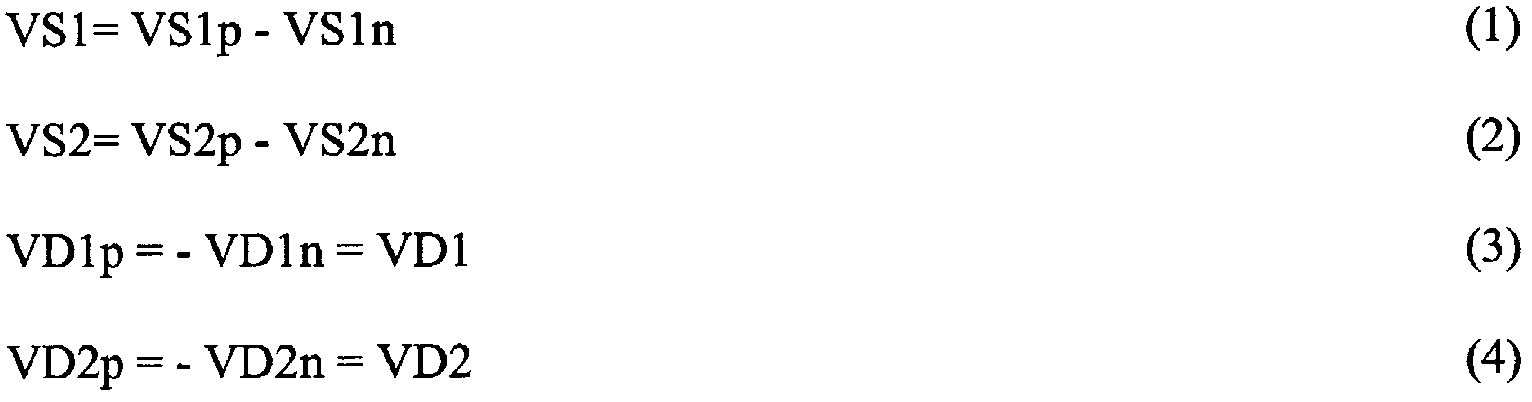
도 5는 전형적인 동작 하에 이용되는 감지 및 제어 전극을 갖춘 모델을 도시하고 있다. 유한요소 분석 모델(500)은 인접한 감지 또는 구동전극에 따라 표시된 세그먼트를 갖는 예시적인 디스크 공진기의 내부 링을 묘사하는 2440개의 노드를 구비한다. 도 5에 나타낸 8개의 캐패시턴스 감지전극 세그먼트 또는 세트는, 디스크 공진기 자이로스코프의 통상 동작에서 이용되는 바와 같은 4개의 캐패시턴스쌍, S1p, S1n, S2p, S2n으로 배선된다. 이 경우, 평면 공진기의 중앙 실장점의 반대측에 있는 전극의 각기 대향하는 감지쌍은 구별되지 않는 바, 전극쌍은 전기적으로 결합되어 있다. 마찬가지로, 제어전극 세그먼트 또는 세트는 4개의 캐패시턴스쌍, D1p, D1n, D2p, D2n으로 배선된다. 여기에서도, 평면 공진기의 중앙 실장점의 반대측에 있는 전극의 각기 대향하는 구동쌍은 구별되지 않는다. 전극은 (예컨대, 도 1b에 개략적으로 나타낸 바와 같은) 제어회로에 접속되어 있는 디스크 공진기를 지지하는 베이스플레이트 상에 배치된 전도성 패턴을 통해 배선되어도 좋음을 이해해야 한다. 공진기 모델의 개별 영역(distinct region)의 감지 및 구동전극은, "*" 또는 "+" 및 라벨링된 S1p, S1n, S2p, S2n, D1p, D1n, D2p 또는 D2n에 의해 표시되어 있다.5 shows a model with sensing and control electrodes used under typical operation. The finite
디스크 공진기 구조는 전압 VGB에 바이어스되어도 좋고, 그라운드로 언급되는 4개의 상호임피던스 캐패시턴스 감지버퍼는 출력전압 VS1p, VS1n, VS2p, VS2n을 산출하도록 전하를 측정하기 위해 이용되어도 좋다. 식별된 축 1 및 2에 관하여 첫번째 2개의 면내 차동모드의 감지 및 제어를 위해, 파라미터는 다음과 같이 정의되어도 좋다:The disc resonator structure may be biased to the voltage VGB, and four mutual impedance capacitance sense buffers referred to as ground may be used to measure the charge to yield the output voltages VS1p, VS1n, VS2p, VS2n. For the detection and control of the first two in-plane differential modes with respect to the identified
이 코리올리 센서 인터페이스는, 2002년 10월 22일 발행된 챌로너(Challoner) 등에 의한 미국 특허 제6,467,346호에 기재되어 있다. 대조적으로, 본 발명의 실시예는 기생모드를 감지 및 제어하고, 구동 및 감지전극쌍의 분할 및 후술하는 바와 같이 자이로스코프의 제어를 강화하고 성능을 향상시키기 위해 각 쌍 사이의 차분 신호를 사용하는 것 등을 이용해도 좋다.This Coriolis sensor interface is described in US Pat. No. 6,467,346 to Challoner et al. Issued October 22, 2002. In contrast, embodiments of the present invention utilize the differential signals between each pair to sense and control parasitic modes, to partition drive and sense electrode pairs, and to enhance the control and improve performance of the gyroscope as described below. You may use a thing.
도 6a는 본 발명에 따른 동작 하에 이용되는 광대한 감지 및 제어 전극을 갖춘 예시적인 모델(600)을 도시하고 있다. 유한요소 분석 모델(600)은 인접한 감지 또는 구동전극에 따라 표시된 세그먼트를 갖는 예시적인 디스크 공진기의 내부 링을 묘사하는 2056개의 노드를 구비한다. 여기에서, 전극쌍은 전기적으로 구별되고 있는 "a" 및 "b" 요소로 분할되어 있다. 첫번째 2개의 면내 공통모드를 능동적으로 감쇠시키도록 감지 및 제어하기 위해, 마스크 배선(mask wiring)은 모두 8개의 용량성 감지전극(4개의 대향하는 전극쌍) S1pa, S1pb, S1na, S1nb, S2pa, S2pb, S2na, S2nb에 대해 개별 액세스가 유지되도록 도 5의 마스크 배선 전체에 걸쳐 변경되어도 좋다. 마찬가지로, 모두 8개의 구동전극 D1pa, D1pb, D1na, D1nb, D2pa, D2pb, D2na, D2nb에 대해 개별 액세스도 유지된다.6A illustrates an
디스크 공진기 구조는 전압 VGB에 바이어스되어도 좋고, 그라운드로 언급되 는 4개의 상호임피던스 캐패시턴스 감지버퍼는 출력전압 VS1pa, VS1pb, VS1na, VS1nb, VS2pa, VS2pb, VS2na, VS2nb를 산출하도록 전하를 측정하기 위해 이용되어도 좋다. 8개의 상호임피던스 캐패시턴스 감지버퍼(상호임피던스 증폭기라고도 함)를 사용함으로써, 전극쌍 사이의 다음의 차분신호가 정의되어도 좋다. 미국 특허 제6,467,346호에 기재된 것과 마찬가지의 인터페이스를 한 예에 이용해도 좋다.The disc resonator structure may be biased to the voltage VGB, and four mutual impedance capacitance sensing buffers referred to as ground are used to measure the charge to yield the output voltages VS1pa, VS1pb, VS1na, VS1nb, VS2pa, VS2pb, VS2na, and VS2nb. It may be. By using eight mutual impedance capacitance sensing buffers (also called mutual impedance amplifiers), the following differential signal between the electrode pairs may be defined. An interface similar to that described in US Pat. No. 6,467,346 may be used in one example.

충분한 차동모드 관찰가능성(observability) 및 제어가 다음의 신호를 정의함으로써 유지될 수 있는 동안 충분한 공통모드 관찰가능성 및 제어를 제공한다.Provides sufficient common mode observability and control while sufficient differential mode observability and control can be maintained by defining the following signals.

능동 감쇠는, 기생 면내 공통모드의 각각의 감쇠를 제공하는 안티-노드 감지 및 제어 캐패시턴스 신호쌍, VS1', VD1' 및 VS2', VD2'로 실현되어도 좋다. 능동 감쇠는 간단히 다음의 예시적인 제어 법칙을 이용해서 아날로그 연산 증폭기 또는 디지탈 피드백으로 적용되어도 좋다.Active attenuation may be realized with anti-node sense and control capacitance signal pairs, VS1 ', VD1' and VS2 ', VD2' providing respective attenuation of the parasitic in-plane common mode. Active attenuation may simply be applied as an analog op amp or digital feedback using the following example control rule.

피드백 이득은 감쇠 시정수를 정의하도록 선택되어도 좋다. 상호임피던스 증폭기 신호가 모델의 속도에 비례하고, 그에 따라 이 간단한 비례하는 용량성 힘 피드백은 충분하다.The feedback gain may be chosen to define the attenuation time constant. The mutual impedance amplifier signal is proportional to the speed of the model, so this simple proportional capacitive force feedback is sufficient.
상호임피던스 증폭기 대신에 고임피턴스 전압 플로워(voltage follower) 또는 부트스트랩 버퍼(bootstrap buffer) 등과 같은 다른 용량 모션 센서를 이용해도 좋다. 또한, 기생 공통모드 감쇠를 제공하기 위해 이용되는 차동전극의 근소한 오정합(slight mismatch)으로 인한 차동모드 감지 주파수에서의 임의의 장애를 방지하기 위해, 기생모드 주파수에 중심을 둔 협대역 필터(narrow bandpass filter)를 피드백 이득 K와 연속해서 이용해도 좋다.Instead of a mutual impedance amplifier, other capacitive motion sensors, such as high impedance voltage followers or bootstrap buffers, may be used. In addition, a narrowband filter centered on the parasitic mode frequency is used to prevent any disturbance in the differential mode sense frequency due to the slight mismatch of the differential electrode used to provide parasitic common mode attenuation. bandpass filter) may be used in series with the feedback gain K.
또한, 예컨대 디스크 공진기 자이로스코프의 상호 접속된 링의 위 및/또는 아래의 평면 공진기에 인접한 캐패시턴스 전극을, 디스크 공진기 자이로스코프의 축 및 로킹 모드의 능동적인 감쇠를 위해 이용해도 좋다.Also, for example, capacitance electrodes adjacent to the planar resonators above and / or below the interconnected rings of the disc resonator gyroscope may be used for active attenuation of the axis and locking mode of the disc resonator gyroscope.
도 6b는 본 발명에 따른 동작 하에 이용되는 감지 및 제어 전극을 갖춘 제2의 예시적인 모델(620)을 도시하고 있다. 이 경우, 예시적인 8㎜ 직경의 디스크 공진기의 다수의 상호접속된 링이 모델(620) 내에 묘사되어 있다. 각종의 매립 전극은 명백하게 하기 위해 나타내고 있지 않으나, 결과로서 얻어진 감지 및 구동전극 캐패시턴스는 오히려 후술하는 각 8분 공간(octant)에 대해 지정된다.6B shows a second
DRG의 전형적인 세그먼트화된 전극(segmented electrode)은 도 1d에 묘시되 어 있는 바와 같고, 공진기 디스크의 다수의 상호접속된 링은 도 1c에 묘사된 바와 같다. 각 8분 공간의 감지 및 구동전극은 원주방향 슬롯 내에 매립되어 있고, 각 전극은 (도 1d에서 전술한 바와 같이) 인보드 및 아웃보드 세그먼트로 더 분할되어 있다. 매립 전극은 명백하게 하기 위해 도 6에는 나타내고 있지 않다. 인보드 및 아웃보드 전극은 각각 도 6b에서 그들의 인접한 링 세그먼트 상에 "+" 또는 "●"에 의해 표시되어 있다. 도 6b의 각 전극은 다음의 코딩에 의해 참조되어도 좋다. "s"는 감지전극을 가리키고, "d"는 구동전극을 가리킨다. 홀수, 1, 3, 5 및 7은 제1 축 및 그 직교에 관한 전극군을 식별한다. 마찬가지로, 짝수, 2, 4, 6 및 8은 제2 축 및 그 직교에 관한 전극군을 식별한다. 일례로서, 제1 축의 한 측면에 관한 감지전극은 아웃보드 감지전극(622)에 대해서는 "C1so"로서, 그리고 인보드 감지전극(624)에 대해서는 "C1si"로서 식별된다. 제1 축의 동일 측면에 관한 구동전극은 아웃보드 구동전극(626)에 대해서는 "C1do"이고, 인보드 구동전극에 대해서는 "C1di"이다. 각 8분 공간에서 각 전극은 마찬가지로 식별된다. ("C"는 모든 전극에 적용가능한 캐패시턴스를 가리킨다.) 각 8분 공간에 대한 인보드 및 아웃보드 전극은, 인보드 및 아웃보드 감지 및 구동 캐패시턴스를 생성하기 위해 전기적으로 접속되어 있다. 아웃보드 전극에 비례한 외측 링(outward ring) 모션은 보다 작게 생성되고, 이로써 아웃보드 캐패시턴스를 증가시킨다. 공진기의 주변 둘레의 감지전극이 2개의 슬롯에 설치되어 있음을 이해해야 한다. 이것은, 2개의 행이 특별한 감지전극마다 나타내어져 있음을 의미한다. 이 명명법(nomencalture)은 동작 설명 및 이후의 제어식에 적용가능하다.Typical segmented electrodes of the DRG are as depicted in FIG. 1D, and a number of interconnected rings of the resonator disk are depicted in FIG. 1C. The sensing and driving electrodes of each 8 minute space are embedded in the circumferential slots, and each electrode is further divided into inboard and outboard segments (as described above in FIG. 1D). The buried electrode is not shown in FIG. 6 for clarity. Inboard and outboard electrodes are indicated by "+" or "●" on their adjacent ring segments in FIG. 6B, respectively. Each electrode of FIG. 6B may be referred to by the following coding. "s" indicates a sensing electrode and "d" indicates a driving electrode. Odd, 1, 3, 5, and 7 identify the electrode group with respect to the first axis and its orthogonality. Similarly, the even numbers, 2, 4, 6 and 8 identify the electrode group with respect to the second axis and its orthogonality. As an example, the sensing electrode on one side of the first axis is identified as "C1so" for the
2가지의 축퇴 차동모드를 이용하는 자이로스코프로서의 동작을 위해, 2가지 모드에 대한 감지 및 구동 캐패시턴스는 다음 식에 의해 표시되는 바와 같이 전기적으로 접속되어도 좋다.For operation as a gyroscope using two degenerate differential modes, the sensing and driving capacitances for the two modes may be electrically connected as indicated by the following equation.

공진기 바이어스 전압(VGB) 및 피드백 저항(Rf)을 갖는 상호임피던스 증폭기를 이용하면, 감지 캐패시터와 연관된 출력 감지전압이 다음과 같이 주어져도 좋다.Using a mutual impedance amplifier having a resonator bias voltage VGB and a feedback resistor Rf, the output sense voltage associated with the sense capacitor may be given as follows.

이 때, 차동모드 감지신호(VS1, VS2)는 다음과 같이 출력 감지전압의 조합으로 정의된다.In this case, the differential mode sensing signals VS1 and VS2 are defined as a combination of output sensing voltages as follows.

2가지 차동모드를 제어하기 위해 전압 VD1 및 VD2에 비례하는 정전 구동력을 생성하기 위해, 구동 캐패시턴스에 인가되는 전압, CD1p, CD1n, CD2p, CD2n은 다음과 같이 주어진다.To generate an electrostatic driving force proportional to the voltages VD1 and VD2 for controlling the two differential modes, the voltages applied to the driving capacitances, CD1p, CD1n, CD2p, and CD2n, are given as follows.

이 원래의 캐패시턴스 상호접속은 기생 공통모드의 직접 관찰가능성을 방지한다.This original capacitance interconnect prevents direct observability of the parasitic common mode.
캐패시턴스 상호접속 배선에 대한 변화에 의해, 2가지 기생 공통모드의 안티-노드는 도 6b의 4개의 홀수 번호가 붙여진 8분 공간의 전극으로 충분히 감지되어 감쇠될 수 있다. 8개의 상호임피던스 증폭기를 이용함으로써, 8개의 감지 캐패시턴스가 공통모드와 제1 축을 따라 정렬된 차동모드의 독립된 관찰가능성을 다음과 같이 생성하기 위해 감지되어 결합될 수 있다.By varying the capacitance interconnect wiring, the anti-nodes of the two parasitic common modes can be sufficiently sensed and attenuated by the four odd-numbered eight-minute electrodes of FIG. 6B. By using eight mutual impedance amplifiers, eight sense capacitances can be sensed and combined to produce independent observability of the common mode and the differential mode aligned along the first axis as follows.

제1 축에 대한 차동모드 감지전압은 다음 식에 의해 형성된다.The differential mode sense voltage for the first axis is formed by the following equation.
![]()
![]()
제1 축 차동모드를 제어하기 위해 전압 VD1에 비례하는 정전 구동력을 생성하기 위해, 홀수 번호가 붙여진 구동 캐패시턴스에 인가되는 전압은 다음과 같이 주어진다.In order to generate an electrostatic drive force proportional to the voltage VD1 for controlling the first axis differential mode, the voltage applied to the odd numbered drive capacitance is given as follows.

제2 축 차동모드는 식 (15)∼(30)에서 설명한 원래의 구성에서와 마찬가지로 감지되어 구동되어도 좋다.The second axis differential mode may be sensed and driven as in the original configuration described in equations (15) to (30).
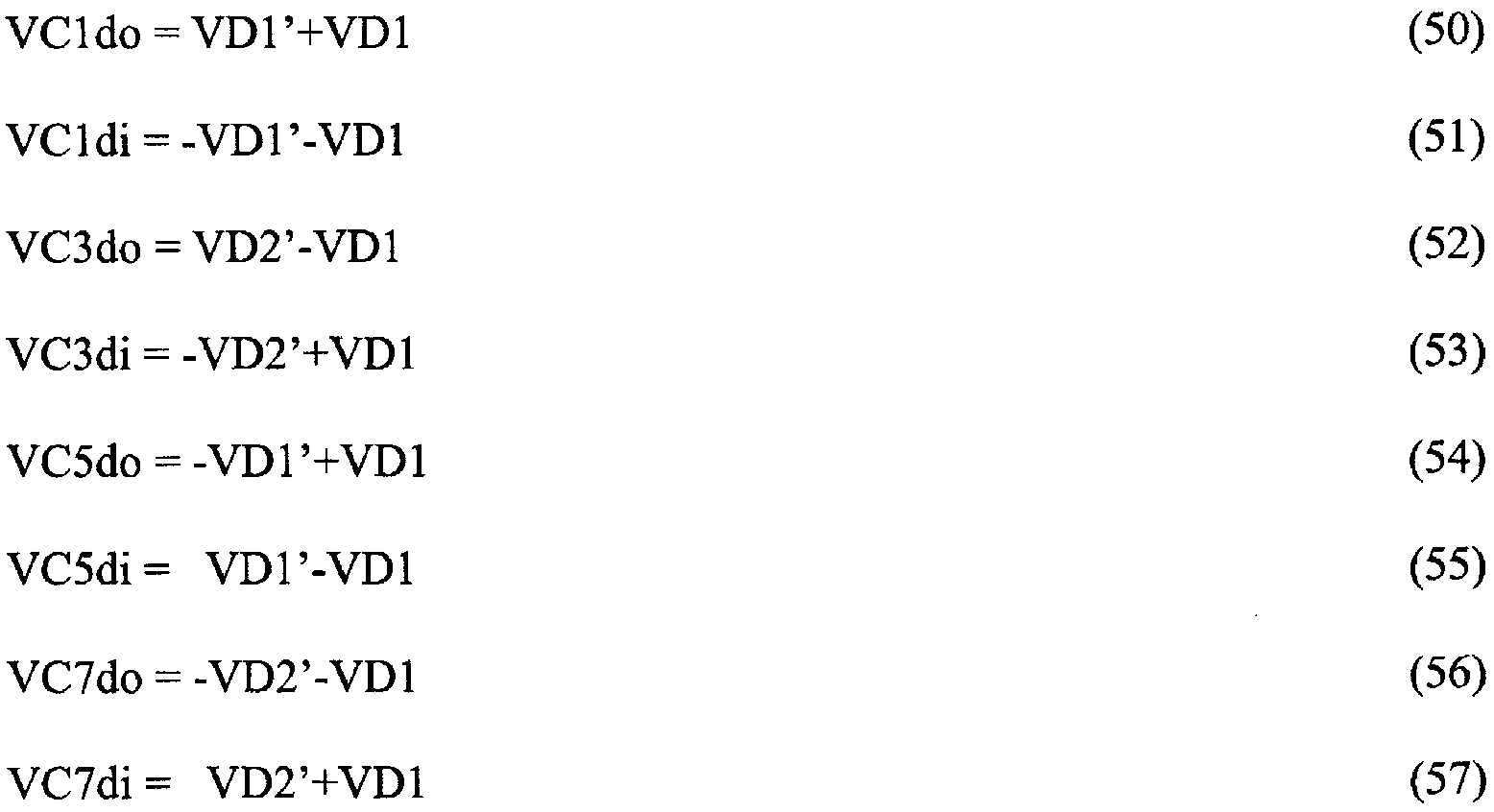
2가지 기생 공통모드를 감지하여 감쇠시킬 목적으로 다음의 신호가 생성된다.The following signals are generated for the purpose of sensing and attenuating the two parasitic common modes.

2가지 공통모드 감지전압은 다음 관계식에 의해 주어진다.The two common mode sense voltages are given by

2가지 차동모드를 제어하기 위해 전압 VD1' 및 VD2'에 비례하고 제1 축 차동모드를 제어하기 위해 VD1에 비례하는 정전 구동력을 생성하기 위해, 홀수 번호가 붙여진 구동 캐패시턴스에 인가되는 전압은 다음과 같이 주어진다.To generate an electrostatic drive force proportional to the voltages VD1 'and VD2' to control the two differential modes and to VD1 to control the first axis differential mode, the voltage applied to the odd-numbered drive capacitance is Is given together.
VS1' 및 VS2'가 캐패시턴스의 변화의 레이트 또는 공진기 속도에 비례하기 때문에, 2가지 기생 공통모드의 능동적인 감쇠가 비례 네가티브 피드백에 의해 간단하게 실현된다.Since VS1 'and VS2' are proportional to the rate of change of capacitance or resonator speed, active attenuation of the two parasitic common modes is simply realized by proportional negative feedback.

K는 고정 이득이고 F(s)는 차동모드 주파수에서 임의의 피드백을 방지하기 위해 이용될 수 있는 공통모드 주파수에 중심을 둔 원래의 협대역 필터이다.K is a fixed gain and F (s) is the original narrowband filter centered at the common mode frequency that can be used to prevent any feedback at the differential mode frequency.
도 6c는 도 6b에서 설명한 바와 같은 본 발명의 실시예를 위한 예시적인 제어회로(640)의 도면이다. 기생모드 감쇠를 위한 디스크 공진기(642), 전극(644, 646) 및 회로(640) 구성의 간단화된 도면에는, 디스크 공진기(642)의 2개의 공진기 링만이 기생모드 편차(parasitic mode deflection)를 따라 나타내어진 것이 도시되어 있다. 감지전극(646)의 하나의 아웃보드 감지 캐패시턴스(C1si) 및 구동전극(644)의 하나의 아웃보드 구동 캐패시턴스(C1di)만이 나타내어져 있다. 추가적인 감지 및 구동전극은, 예컨대 도 6b의 예에서 설명한 바와 같이 추가되어 전기적으로 접속되어도 좋다. 감지전극(646)은 중앙에 실장된 디스크 공진기(642) 상의 구동전극(644) 주변에 배치된다. 바이어스 전압(648; VGB)은 공진기(642)에 인가되고 있다. 감지전극(646)은 Rf 피드백 저항(652)을 통해 출력 감지전압(VS1')을 산출하는 상호임피던스 증폭기(650)에 결합되어 있다. 이 간단화된 경우에 있어서, 출력 감지전압(VS1')은 본질적으로 비례 네가티브 피드백을 갖는 구동전극(644)에 직접 인가되어도 좋다. 비례 네가티브 피드백을 제공하기 위해 고정이 득 증폭기(654)를 이용해도 좋다. 선택적으로, 차동모드 주파수에서 피드백을 최소화하기 위해 공통모드 주파수에 중심을 둔 협대역 필터(656)를 포함해도 좋다.6C is a diagram of an
더욱이, 이 기술분야에서 통상의 지식을 가진 자에 의해 이해되는 바와 같이 본 발명의 실시예에 마찬가지로 적용될 수 있는 디지탈 자이로 제어전극의 예는, 2005년 7월 5일 발행된 엠'클로스키(M'Closkey) 등에 의한 미국 특허 제6,915,215호에서 발견할 수 있다.Moreover, an example of a digital gyro control electrode that can be similarly applied to an embodiment of the present invention as understood by those skilled in the art is M'Kloski (M), issued July 5, 2005. US Pat. No. 6,915,215 to Closkey et al.
도 7은 본 발명에 따른 평면 공진기를 동작시키는 예시적인 방법의 플로우차트이다. 이 방법(700)은, 평면 공진기의 기생 진동모드의 하나 이상의 안티-노드 가까이에 배치된 평면 공진기에 인접한 복수의 용량전극의 하나 이상의 감지전극에 의해 평면 공진기의 기생 진동모드의 진폭을 감지하는 동작(702)으로 시작한다. 다음으로, 동작 704에서는, 기생 진동모드의 진폭에 비례하는 전압이 발생된다. 최후로, 동작 706에서는, 평면 공진기의 기생 진동모드의 하나 이상의 안티-노드 가까이에 배치된 평면 공진기에 인접한 복수의 용량전극의 적어도 하나 이상의 구동전극에 비례전압으로부터 발생한 구동전압을 인가함으로써, 기생모드가 감쇠된다. 이 기본적인 방법(700)은, 예컨대 능동적인 감쇠 및/또는 위치 피드백을 달성하기 위해 상술한 바와 같이 더 변형되어도 좋다.7 is a flowchart of an exemplary method of operating a planar resonator in accordance with the present invention. The
이 발명의 바람직한 실시예 이상의 설명은 도시 및 설명을 위해 이루어졌다. 망라적인 것 또는 개시된 바와 같은 형태에 이 발명을 한정하는 것을 의도하는 것은 아니다. 상기 개시내용에 비추어 다수의 변형례 및 수정례가 가능하다. 이 발명의 범위는 상세한 설명에 의해서가 아니라 이하의 청구의 범위에 의해 한정되는 것이 의도된다. 상기 명세서 및 데이터는 이 발명의 제조 및 사용의 완전한 설명을 제공한다. 이 발명의 범위로부터 이탈하는 일없이 이 발명의 다수의 실시예를 이룰 수 있으므로, 이 발명은 첨부의 청구의 범위에 속한다.Preferred Embodiments of the Invention The above description has been made for the purposes of illustration and description. It is not intended to be exhaustive or to limit the invention to the form as disclosed. Many modifications and variations are possible in light of the above disclosure. It is intended that the scope of the invention be limited not by this detailed description, but rather by the claims below. The above specification and data provide a complete description of the manufacture and use of this invention. Since many embodiments of the invention can be made without departing from the scope of the invention, the invention resides in the appended claims.
Claims (21)
Applications Claiming Priority (3)
| Application Number | Priority Date | Filing Date | Title |
|---|---|---|---|
| US11/615,872 | 2006-12-22 | ||
| US11/615,872 US7493814B2 (en) | 2006-12-22 | 2006-12-22 | Vibratory gyroscope with parasitic mode damping |
| PCT/US2007/088286 WO2008079930A1 (en) | 2006-12-22 | 2007-12-20 | Vibratory gyroscope with parasitic mode damping |
Publications (2)
| Publication Number | Publication Date |
|---|---|
| KR20090091295A true KR20090091295A (en) | 2009-08-27 |
| KR101412877B1 KR101412877B1 (en) | 2014-06-26 |
Family
ID=39345457
Family Applications (1)
| Application Number | Title | Priority Date | Filing Date |
|---|---|---|---|
| KR1020097010024A KR101412877B1 (en) | 2006-12-22 | 2007-12-20 | Vibratory gyroscope with parasitic mode damping |
Country Status (8)
| Country | Link |
|---|---|
| US (1) | US7493814B2 (en) |
| JP (1) | JP5389664B2 (en) |
| KR (1) | KR101412877B1 (en) |
| CN (1) | CN101542234B (en) |
| AU (1) | AU2007336930B2 (en) |
| CA (1) | CA2663520C (en) |
| GB (1) | GB2455455B (en) |
| WO (1) | WO2008079930A1 (en) |
Cited By (2)
| Publication number | Priority date | Publication date | Assignee | Title |
|---|---|---|---|---|
| KR101423528B1 (en) * | 2012-06-04 | 2014-08-13 | 한국항공우주연구원 | Anti-rolling gyroscope |
| RU2735490C1 (en) * | 2020-03-12 | 2020-11-03 | Акционерное общество "Научно-исследовательский институт "Полюс" им. М.Ф. Стельмаха" | Method of determining sensitivity coefficient of perimeter of resonator of zeeman ring laser to effect of linear accelerations |
Families Citing this family (50)
| Publication number | Priority date | Publication date | Assignee | Title |
|---|---|---|---|---|
| US8766745B1 (en) * | 2007-07-25 | 2014-07-01 | Hrl Laboratories, Llc | Quartz-based disk resonator gyro with ultra-thin conductive outer electrodes and method of making same |
| US7994877B1 (en) | 2008-11-10 | 2011-08-09 | Hrl Laboratories, Llc | MEMS-based quartz hybrid filters and a method of making the same |
| US7543496B2 (en) | 2006-03-27 | 2009-06-09 | Georgia Tech Research Corporation | Capacitive bulk acoustic wave disk gyroscopes |
| US7767484B2 (en) | 2006-05-31 | 2010-08-03 | Georgia Tech Research Corporation | Method for sealing and backside releasing of microelectromechanical systems |
| US7555824B2 (en) * | 2006-08-09 | 2009-07-07 | Hrl Laboratories, Llc | Method for large scale integration of quartz-based devices |
| US8061201B2 (en) | 2007-07-13 | 2011-11-22 | Georgia Tech Research Corporation | Readout method and electronic bandwidth control for a silicon in-plane tuning fork gyroscope |
| US10266398B1 (en) | 2007-07-25 | 2019-04-23 | Hrl Laboratories, Llc | ALD metal coatings for high Q MEMS structures |
| US7836765B2 (en) | 2007-07-31 | 2010-11-23 | The Boeing Company | Disc resonator integral inertial measurement unit |
| US8151640B1 (en) * | 2008-02-05 | 2012-04-10 | Hrl Laboratories, Llc | MEMS on-chip inertial navigation system with error correction |
| US7802356B1 (en) | 2008-02-21 | 2010-09-28 | Hrl Laboratories, Llc | Method of fabricating an ultra thin quartz resonator component |
| JP5587917B2 (en) * | 2009-03-13 | 2014-09-10 | カール・ツァイス・エスエムティー・ゲーエムベーハー | Microlithography projection exposure apparatus |
| US8393212B2 (en) * | 2009-04-01 | 2013-03-12 | The Boeing Company | Environmentally robust disc resonator gyroscope |
| US8418554B2 (en) * | 2009-06-01 | 2013-04-16 | The Boeing Company | Gyroscope packaging assembly |
| WO2011026100A1 (en) | 2009-08-31 | 2011-03-03 | Georgia Tech Research Corporation | Bulk acoustic wave gyroscope with spoked structure |
| US8176607B1 (en) | 2009-10-08 | 2012-05-15 | Hrl Laboratories, Llc | Method of fabricating quartz resonators |
| DE102010029707B4 (en) | 2010-06-04 | 2024-02-15 | Robert Bosch Gmbh | Energy-saving microsystem, method for controlling a microsystem and computer program product |
| US8912711B1 (en) | 2010-06-22 | 2014-12-16 | Hrl Laboratories, Llc | Thermal stress resistant resonator, and a method for fabricating same |
| KR101319712B1 (en) * | 2011-12-26 | 2013-10-17 | 삼성전기주식회사 | Gyro sensor drive circuit, gyro sensor system and method for driving gyro sensor |
| DE102011057169A1 (en) * | 2011-12-29 | 2013-07-04 | Maxim Integrated Products, Inc. | Microelectromechanical system |
| US8890446B2 (en) * | 2012-11-14 | 2014-11-18 | Northrop Grumman Systems Corporation | Amplitude control for vibrating resonant sensors |
| JP5988494B2 (en) * | 2013-02-04 | 2016-09-07 | 富士フイルム株式会社 | Angular velocity sensor and manufacturing method thereof |
| US9202351B2 (en) * | 2013-03-11 | 2015-12-01 | Immersion Corporation | Systems and methods for haptics in vibrating environments and devices |
| US9250074B1 (en) | 2013-04-12 | 2016-02-02 | Hrl Laboratories, Llc | Resonator assembly comprising a silicon resonator and a quartz resonator |
| US9599470B1 (en) | 2013-09-11 | 2017-03-21 | Hrl Laboratories, Llc | Dielectric high Q MEMS shell gyroscope structure |
| US20150168146A1 (en) * | 2013-12-13 | 2015-06-18 | Sensors In Motion | Planar accelerometer with internal radial sensing and actuation |
| US9977097B1 (en) | 2014-02-21 | 2018-05-22 | Hrl Laboratories, Llc | Micro-scale piezoelectric resonating magnetometer |
| US9523577B1 (en) | 2014-02-27 | 2016-12-20 | The United States Of America As Represented By The Administrator Of The National Aeronautics And Space Administration | Carbon nanotube tape vibrating gyroscope |
| US9991863B1 (en) | 2014-04-08 | 2018-06-05 | Hrl Laboratories, Llc | Rounded and curved integrated tethers for quartz resonators |
| US10308505B1 (en) | 2014-08-11 | 2019-06-04 | Hrl Laboratories, Llc | Method and apparatus for the monolithic encapsulation of a micro-scale inertial navigation sensor suite |
| US10031191B1 (en) | 2015-01-16 | 2018-07-24 | Hrl Laboratories, Llc | Piezoelectric magnetometer capable of sensing a magnetic field in multiple vectors |
| US10502568B2 (en) | 2015-04-29 | 2019-12-10 | General Electric Company | Inertial sensing systems and methods of manufacturing the same |
| CN104976996B (en) * | 2015-08-07 | 2017-11-21 | 中国人民解放军国防科学技术大学 | Nested ring type MEMS oscillation gyros with period profile lumped mass block |
| CN104976995B (en) * | 2015-08-07 | 2018-05-25 | 中国人民解放军国防科学技术大学 | Become the nested ring type MEMS oscillation gyros of resonant ring wall thickness |
| US10794700B1 (en) * | 2015-10-30 | 2020-10-06 | Garmin International, Inc. | Stress isolation of resonating gyroscopes |
| CN105371833B (en) * | 2015-11-19 | 2018-03-23 | 上海交通大学 | A kind of polycyclic outer S-shaped flexible beam resonant gyroscope of disk and preparation method thereof |
| CN105486297B (en) * | 2015-11-19 | 2018-05-29 | 上海交通大学 | A kind of polycyclic interior S-shaped flexible beam resonant gyroscope of disk and preparation method thereof |
| CN105371832B (en) * | 2015-11-19 | 2018-02-09 | 上海交通大学 | A kind of polycyclic interior twin beams of disk isolates annulus resonant gyroscope and preparation method thereof |
| US10877063B2 (en) * | 2015-12-10 | 2020-12-29 | Invensense, Inc. | MEMS sensor with compensation of residual voltage |
| US10110198B1 (en) | 2015-12-17 | 2018-10-23 | Hrl Laboratories, Llc | Integrated quartz MEMS tuning fork resonator/oscillator |
| US10175307B1 (en) | 2016-01-15 | 2019-01-08 | Hrl Laboratories, Llc | FM demodulation system for quartz MEMS magnetometer |
| US10527419B1 (en) * | 2016-02-17 | 2020-01-07 | Inertialwave | Baseband control electronics for inertial wave angle gyroscope |
| JP6571065B2 (en) | 2016-12-08 | 2019-09-04 | 株式会社東芝 | Vibration device |
| CN106629576A (en) * | 2016-12-29 | 2017-05-10 | 北京时代民芯科技有限公司 | Silicon-based MEMS dish top |
| CN110998231B (en) | 2017-08-08 | 2023-11-10 | Hrl实验室有限责任公司 | High-quality factor MEMS silicon life fancy vibration gyroscope |
| EP3679322B1 (en) * | 2017-09-07 | 2023-05-10 | HRL Laboratories, LLC | High quality factor mems silicon hinge and slot-cut resonator for a vibratory gyroscope |
| JP6759259B2 (en) | 2018-02-28 | 2020-09-23 | 株式会社東芝 | Vibration device |
| CN108613669B (en) * | 2018-06-27 | 2022-02-22 | 苏州文智芯微系统技术有限公司 | Regular polygon disc-shaped MEMS (micro-electromechanical systems) resonance gyroscope |
| CN109186577A (en) * | 2018-10-29 | 2019-01-11 | 西北工业大学 | A kind of novel positive twelve edge annular resonance declines mechanical gyro |
| CN109186576A (en) * | 2018-10-29 | 2019-01-11 | 西北工业大学 | A kind of novel positive eight sides annular resonant-type micro-mechanical optic fiber gyroscope |
| RU2704334C1 (en) * | 2019-04-02 | 2019-10-28 | Федеральное государственное бюджетное учреждение науки Институт проблем механики им. А.Ю. Ишлинского Российской академии наук | Method of reading and controlling oscillations of wave solid-state gyroscope |
Family Cites Families (15)
| Publication number | Priority date | Publication date | Assignee | Title |
|---|---|---|---|---|
| US5383362A (en) * | 1993-02-01 | 1995-01-24 | General Motors Corporation | Control for vibratory gyroscope |
| JPH08159776A (en) * | 1994-12-08 | 1996-06-21 | Nissan Motor Co Ltd | Angular velocity sensor |
| US5616864A (en) * | 1995-02-22 | 1997-04-01 | Delco Electronics Corp. | Method and apparatus for compensation of micromachined sensors |
| JP3409520B2 (en) * | 1995-08-01 | 2003-05-26 | 日産自動車株式会社 | Angular velocity sensor |
| DE19619585C2 (en) * | 1996-05-15 | 1999-11-11 | Bosch Gmbh Robert | Switchable planar high-frequency resonator and filter |
| GB2335273B (en) * | 1998-03-14 | 2002-02-27 | British Aerospace | A two axis gyroscope |
| GB0001294D0 (en) * | 2000-01-20 | 2000-03-08 | British Aerospace | Multi-axis sensing device |
| US6467346B1 (en) * | 2000-06-14 | 2002-10-22 | Hughes Electronics Corporation | Coriolis sensor interface |
| US20030033850A1 (en) * | 2001-08-09 | 2003-02-20 | Challoner A. Dorian | Cloverleaf microgyroscope with electrostatic alignment and tuning |
| US6675630B2 (en) * | 2001-08-17 | 2004-01-13 | The Boeing Company | Microgyroscope with electronic alignment and tuning |
| GB0206510D0 (en) * | 2002-03-20 | 2002-05-01 | Qinetiq Ltd | Micro-Electromechanical systems |
| US6944931B2 (en) | 2002-08-12 | 2005-09-20 | The Boeing Company | Method of producing an integral resonator sensor and case |
| US7040163B2 (en) | 2002-08-12 | 2006-05-09 | The Boeing Company | Isolated planar gyroscope with internal radial sensing and actuation |
| JP4698221B2 (en) * | 2002-08-12 | 2011-06-08 | ザ・ボーイング・カンパニー | Separate planar gyroscope with internal radial sensing and actuation |
| JP4556515B2 (en) * | 2004-07-02 | 2010-10-06 | 株式会社デンソー | Angular velocity sensor |
-
2006
- 2006-12-22 US US11/615,872 patent/US7493814B2/en active Active
-
2007
- 2007-12-20 AU AU2007336930A patent/AU2007336930B2/en active Active
- 2007-12-20 CA CA2663520A patent/CA2663520C/en active Active
- 2007-12-20 WO PCT/US2007/088286 patent/WO2008079930A1/en active Application Filing
- 2007-12-20 JP JP2009543208A patent/JP5389664B2/en active Active
- 2007-12-20 KR KR1020097010024A patent/KR101412877B1/en active IP Right Grant
- 2007-12-20 CN CN2007800420966A patent/CN101542234B/en active Active
- 2007-12-20 GB GB0904811A patent/GB2455455B/en active Active
Cited By (2)
| Publication number | Priority date | Publication date | Assignee | Title |
|---|---|---|---|---|
| KR101423528B1 (en) * | 2012-06-04 | 2014-08-13 | 한국항공우주연구원 | Anti-rolling gyroscope |
| RU2735490C1 (en) * | 2020-03-12 | 2020-11-03 | Акционерное общество "Научно-исследовательский институт "Полюс" им. М.Ф. Стельмаха" | Method of determining sensitivity coefficient of perimeter of resonator of zeeman ring laser to effect of linear accelerations |
Also Published As
| Publication number | Publication date |
|---|---|
| CA2663520A1 (en) | 2008-07-03 |
| CA2663520C (en) | 2016-04-19 |
| AU2007336930B2 (en) | 2013-08-22 |
| CN101542234A (en) | 2009-09-23 |
| GB2455455B (en) | 2011-06-29 |
| KR101412877B1 (en) | 2014-06-26 |
| CN101542234B (en) | 2011-12-07 |
| GB2455455A (en) | 2009-06-17 |
| US20080148846A1 (en) | 2008-06-26 |
| AU2007336930A1 (en) | 2008-07-03 |
| WO2008079930A1 (en) | 2008-07-03 |
| JP5389664B2 (en) | 2014-01-15 |
| JP2010515021A (en) | 2010-05-06 |
| US7493814B2 (en) | 2009-02-24 |
| GB0904811D0 (en) | 2009-05-06 |
Similar Documents
| Publication | Publication Date | Title |
|---|---|---|
| KR101412877B1 (en) | Vibratory gyroscope with parasitic mode damping | |
| CA2636682C (en) | Disc resonator integral inertial measurement unit | |
| EP1415127B1 (en) | Isolated resonator gyroscope | |
| US7093486B2 (en) | Isolated resonator gyroscope with a drive and sense plate | |
| EP0902875B1 (en) | Silicon macromachined symmetric vibratory gyroscope sensor | |
| US7793541B2 (en) | Planar resonator gyroscope central die attachment | |
| US8418554B2 (en) | Gyroscope packaging assembly | |
| JPH10160483A (en) | Rate sensor | |
| US6990863B2 (en) | Isolated resonator gyroscope with isolation trimming using a secondary element | |
| US6955084B2 (en) | Isolated resonator gyroscope with compact flexures | |
| Parajuli | A high-Q micromachined quatrefoil suspension gyroscope | |
| Sabageh | Design and modeling of decoupled and tunable bandwidth (40-330 Hz) MEMS vibratory gyroscopes | |
| EP1571416A2 (en) | Support of vibrating beam near nodal point | |
| US7322238B2 (en) | Support of vibrating beam near nodal point |
Legal Events
| Date | Code | Title | Description |
|---|---|---|---|
| A201 | Request for examination | ||
| E902 | Notification of reason for refusal | ||
| E701 | Decision to grant or registration of patent right | ||
| GRNT | Written decision to grant | ||
| FPAY | Annual fee payment |
Payment date: 20170612 Year of fee payment: 4 |
|
| FPAY | Annual fee payment |
Payment date: 20190612 Year of fee payment: 6 |