KR20090076216A - Mesh dipper courage and conductive board for induction range - Google Patents
Mesh dipper courage and conductive board for induction range Download PDFInfo
- Publication number
- KR20090076216A KR20090076216A KR1020080002026A KR20080002026A KR20090076216A KR 20090076216 A KR20090076216 A KR 20090076216A KR 1020080002026 A KR1020080002026 A KR 1020080002026A KR 20080002026 A KR20080002026 A KR 20080002026A KR 20090076216 A KR20090076216 A KR 20090076216A
- Authority
- KR
- South Korea
- Prior art keywords
- conductive plate
- cooking vessel
- rivet
- induction range
- conductive board
- Prior art date
Links
Images


Classifications
-
- A—HUMAN NECESSITIES
- A47—FURNITURE; DOMESTIC ARTICLES OR APPLIANCES; COFFEE MILLS; SPICE MILLS; SUCTION CLEANERS IN GENERAL
- A47J—KITCHEN EQUIPMENT; COFFEE MILLS; SPICE MILLS; APPARATUS FOR MAKING BEVERAGES
- A47J36/00—Parts, details or accessories of cooking-vessels
- A47J36/02—Selection of specific materials, e.g. heavy bottoms with copper inlay or with insulating inlay
Abstract
Description
도 1은 본 발명의 도전판재에 리벳을 제거한 사시도1 is a perspective view of removing the rivet on the conductive plate of the present invention
도 2는 도 1의 일부분을 확대한 단면도2 is an enlarged cross-sectional view of a portion of FIG. 1;
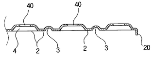
도 3은 본 발명에 의한 도전판재의 주요부를 보인 단면도Figure 3 is a cross-sectional view showing the main part of the conductive plate material according to the present invention
도 4는 도 3의 요부를 확대한 단면도4 is an enlarged cross-sectional view of the main portion of FIG.
도 5는 도전판재의 또 다른 구성의 요부를 보인 단면도5 is a cross-sectional view showing the main parts of still another configuration of the conductive plate material.
도 6은 금형에 본 발명에 의한 도전판재가 놓여진 상태를 보인 단면도6 is a cross-sectional view showing a state in which a conductive plate material according to the present invention is placed in a mold.
도 7은 도전판재와 조리용기가 일체로 성형된 상태를 보인 단면도7 is a cross-sectional view showing a state in which the conductive plate and the cooking vessel are integrally formed.
도 8은 본 발명에 의한 인덕션레인지용 조리용기의 부분 단면도8 is a partial cross-sectional view of the cooking container for induction range according to the present invention.
***도면의 주요부분에 대한 부호의 설명****** Explanation of symbols for main parts of drawing ***
1: 도전판재 1: conductive plate
2: 돌출부 2: protrusion
3: 보강홈 3: reinforcement groove
4: 리벳머리 안착홈 4: rivet head seating groove
5: 리벳 5: rivet
8: 조리용기 8: cooking vessel
40: 리벳구멍 40: rivet hole
50: 리벳몸체 확장부 50: rivet body extension
80: 조리용기 밑면 80: bottom of cooking vessel
500: 홈 500: home
본 발명은 인덕션레인지용 조리용기 및 도전판재에 관한 것으로서, 더욱 상세하게는 조리용기를 제조시 도전판재를 알루미늄 등 비도전성 재질을 몰드에 주입하여 조리용기의 밑면에 도전판재가 일체로 형성된 조리용기와, 상기와 같은 조리용기를 제공하기 위한 도전판재의 구성에 관한 것이다.The present invention relates to a cooking vessel and a conductive plate material for an induction range, and more particularly, to a cooking vessel in which a conductive plate material is integrally formed on the bottom surface of a cooking container by injecting a conductive plate material into a mold when the conductive plate material is manufactured. And, it relates to a configuration of a conductive plate for providing a cooking vessel as described above.
주지하는 바와 같이 인덕션레인지는 사용시 유해가스가 발생하지 않고 불꽃이 없어 화재의 위험이 없으며, 특히 실내공기를 쾌적하게 하는 장점으로 인하여 요식업계에서 많이 사용되고, 일반 가정에서도 안전성이 좋고, 친환경적인 인덕션레인지를 선호하고 사용함에 따라 그에 알맞은 인덕션레인지용 조리용기의 수요가 더욱 증가할 것으로 전망된다.As is well known, the induction range does not generate harmful gas and there is no spark and there is no danger of fire.In particular, the induction range is widely used in the food industry due to the advantages of making indoor air more comfortable. According to the preference and use of the induction range cooker is expected to further increase.
종래 상기와 같은 인덕션레인지에 사용할 수 있는 조리용기의 구조를 살펴보면, 조리용기의 경량화를 위하여 조리용기는 비교적 가벼운 비도전성 금속재질인 알루미늄으로 구성하면서 조리용기의 밑면에는 조리용기의 내용물을 가열하기 위하여 인덕션레인지로부터의 자장과 감응하는 도전성 금속재질인 철이나 합금 등으로 이루어지는 도전판재의 테두리가 조리용기의 밑면에 심어지는 형태로 부착되어 있는 것이 있다.Looking at the structure of the cooking vessel that can be used in the conventional induction range as described above, in order to reduce the weight of the cooking vessel, the cooking vessel is made of aluminum, which is a relatively light non-conductive metal material, and to heat the contents of the cooking vessel on the bottom of the cooking vessel. In some cases, the edge of the conductive plate made of iron or an alloy, which is a conductive metal material sensitive to the magnetic field from the induction range, is attached to the bottom of the cooking vessel.
그런데, 조리용기의 밑면에 일체로 형성되는 도전판재의 테두리만 심어지는 형태로 되어 있기 때문에 부착력이 부족하여 장기간 사용하다 보면 도전판재가 조리용기로부터 분리되는 문제가 있었고, 이로 인해 조리용기의 사용이 불가능하게 되는 단점이 있었다.However, since only the edge of the conductive plate formed integrally on the bottom of the cooking vessel is planted, there is a problem in that the conductive plate is separated from the cooking vessel when it is used for a long period of time due to insufficient adhesive force, which causes the use of the cooking vessel. There was a drawback to being impossible.
이러한 단점들을 해결하기 위하여 도전판재를 부분적으로 펀칭하여 돌출부를 만들어주고, 상기 돌출부가 조리용기에 밑면에 골고루 심어지게 하면서 도전판재의 일부분이 노출되어 조리용기의 일부분이 되도록 구성된 것이 있다.In order to solve these shortcomings, the conductive plate is partially punched to make a protrusion, and the protrusion is evenly planted on the bottom of the cooking vessel, so that a portion of the conductive plate is exposed to be part of the cooking vessel.
그러나, 이러한 경우에도 조리용기와 도전판재간에 서로 다른 열팽창계수에 의해서 조리용기와 도전판재의 돌출부간에 서서히 틈새가 발생하게 되고, 조리용기와 도전판재간이 분리될 수밖에 없어 결국 조리용기를 사용할 수 없게 되는 단점을 해결하지 못하였다.However, even in such a case, the gap between the cooking vessel and the conductive plate member is gradually generated by different thermal expansion coefficients between the cooking vessel and the conductive plate member, and the cooking vessel and the conductive plate member have to be separated. It did not solve the shortcomings.
이러한 단점들을 해결하기 위하여 본원의 출원인이 선출원한 조리용기의 도전판재를 이용한 조리용기가 있으나 도전판재가 평판으로 구성되었기 때문에 내구성이 부족하여 밴딩현상이 있고, 또 평판이기 때문에 디자인적으로 단순하여 상품적 가치가 떨어지는 단점이 있으며, 또한 조리용기의 밑면에 도전판재가 부착됨에 있어 철망에만 의존하는 관계로 견고한 결합상태를 유지하지 못하였고, 또 철망이 용접되는 부분이 변색되는 등의 단점이 있었다.In order to solve these shortcomings, the applicant of the present application is a cooking vessel using the conductive plate material of the cooking vessel, which is filed by the applicant of the present application, but since the conductive plate material is composed of a flat plate, there is a lack of durability and a flat design. There is a disadvantage in that the enemy value is lower, and also because the conductive plate is attached to the bottom of the cooking vessel because it depends only on the wire mesh, it could not maintain a firm coupling state, and there were disadvantages such as discoloration of the welded wire mesh.
상기한 문제점들을 해결하기 위한 본 발명은 인덕션레인지용 조리용기 및 도전판재는 도전판재가 조리용기의 밑면에 일체로 고정된 상태에서 조리용기를 가열시 조리용기와 도전판재가 서로 다른 팽창계수의 영향을 받는 경우에도 상호 부착된 상태에서 유격이 발생하지 않고 내구성이 향상되게 하며, 또 디자인적으로 매우 우수한 인덕션레인지용 조리용기를 제공할 수 있게 하며, 또한 상기와 같은 인덕션레인지용 조리용기를 제공할 수 있는 도전판재를 도전성 금속재질인 철이나 합금으로 간편하게 구성된 도전판재를 제공하는데 소기의 목적하는 바가 있다.According to the present invention for solving the above problems, the induction range cooking vessel and the conductive plate member has the influence of the expansion coefficient different from the cooking vessel and the conductive plate member when heating the cooking vessel in a state where the conductive plate is fixed to the bottom of the cooking vessel integrally Even when receiving, it is possible to improve the durability of the induction range cooking container without generating a gap in the state attached to each other, and also to provide the induction range cooking container as described above. The purpose of the present invention is to provide a conductive plate material which is simply composed of iron or an alloy that is a conductive metal material.
상기 목적을 달성하기 위한 본 발명의 인덕션레인지용 조리용기의 도전판재 는 내구성을 향상시키고, 디자인적으로 미려함을 주기 위하여 원형의 돌출부와 보강홈이 반복적으로 형성되도록 구성하고, 특히 조리용기의 밑면에 심어지도록 리벳들이 일체로 형성하여 구성된 도전판재와, 상기와 같이 구성된 도전판재를 조리용기의 밑면에 인서트식으로 부착하여 구성된 인덕션레인지용 조리용기를 특징으로 하며, 이하 첨부된 도면과 관련하여 상세하게 설명하면 다음과 같다.The conductive plate of the induction range cooking vessel of the present invention for achieving the above object is configured to be repeatedly formed of a circular protrusion and a reinforcement groove in order to improve durability and give a beautiful design, especially in the bottom of the cooking vessel A conductive plate material formed by integrally forming rivets to be planted, and an induction range cooking container configured by attaching the conductive plate material configured as described above to an underside of the cooking container, are described in detail with reference to the accompanying drawings. The explanation is as follows.
도 1은 본 발명의 도전판재에 리벳을 제거한 사시도, 도 2는 도 1의 일부분을 확대한 단면도, 도 3은 본 발명에 의한 도전판재의 주요부를 보인 단면도, 도 4는 도 3의 요부를 확대한 단면도, 도 5는 도전판재의 또 다른 구성의 요부를 보인 단면도, 도 6은 금형에 본 발명에 의한 도전판재가 놓여진 상태를 보인 단면도, 도 7은 도전판재와 조리용기가 일체로 성형된 상태를 보인 단면도, 도 8은 본 발명에 의한 인덕션레인지용 조리용기의 부분 단면도이다.1 is a perspective view of the conductive plate material of the present invention without the rivets, Figure 2 is an enlarged cross-sectional view of a portion of Figure 1, Figure 3 is a sectional view showing the main portion of the conductive plate material according to the present invention, Figure 4 is an enlarged main portion of Figure 3 5 is a cross-sectional view showing the main part of another configuration of the conductive plate material, Figure 6 is a cross-sectional view showing a state where the conductive plate material according to the present invention is placed in the mold, Figure 7 is a state in which the conductive plate material and the cooking vessel are integrally molded 8 is a partial cross-sectional view of the induction range cooking vessel according to the present invention.
본 발명의 인덕션레인지용 조리용기의 밑면에 부착되는 도전판재를 구성함에 있어서,In constructing a conductive plate attached to the bottom of the induction range cooking vessel of the present invention,
도전판재(1)는 내구성을 향상시키고, 디자인적으로 미려함을 주기 위하여 원형의 돌출부(2)와 보강홈(3)이 반복적으로 형성되게 구성하며,The
상기와 같이 구성된 도전판재(1)의 돌출부(2)에는 리벳구멍(40)이 형성된 리벳머리 안착홈(4)들을 소정의 간격으로 형성하여 리벳(5)을 결합하여 내측에 리벳몸체 확장부(50)를 형성하여 도전판재(1)를 구성하며,Rivet body seating portions (4) formed as described above are formed at predetermined intervals with the rivet head seating grooves (4) having the rivet holes (40) formed therebetween by combining the rivets (5). 50 to form a conductive plate (1),
본 발명의 또 다른 구성으로는 상기 도전판재(1)를 구성하는 리벳(5)들의 내측에 형성된 리벳몸체 확장부(50)에는 홈(500)들을 형성할 수 있다.In another configuration of the present invention,
이렇게 구성된 도전판재(1)는 다이케스팅 금형(7)에 넣고 알루미늄과 같은 재료를 주입하여 조리용기(8)를 성형시 조리용기의 밑면(80)에 상기 도전판재(1)가 일체로 부착성형되며,The
상기 도전판재(1)를 구성하는 리벳몸체 확장부(50)들이 조리용기(8)를 성형시 조리용기의 밑면(80)에 인서트되어 일체로 매립되어 구성된다.The rivet
도면의 미설명부호 20은 절곡부를 표시한 것이다.
이상과 같은 본 발명의 인덕션레인지용 조리용기에 관한 작용을 상세하게 설명하면 다음과 같다.Referring to the operation of the induction range cooking vessel of the present invention in detail as follows.
본 발명에 의하면, 우선 도전판재(1)를 구성하는 돌출부(2)와 보강홈(3)이 원형으로 반복 구성됨으로써, 조리용기의 밑면(80)을 구성시 디자인적으로 미려함을 줄 수 있게 되고, 동시에 도전판재(1)의 내구성을 향상시켜줌으로써, 도전판재가 밴딩되거나 부분적으로 눌려지는 것을 방지할 수 있는 작용을 한다.According to the present invention, first, since the
그리고, 도전판재(1)의 내면이 조리용기의 밑면에 부착되면, 도전판재(1)를 구성하는 리벳몸체 확장부(50)가 소정의 간격으로 조리용기의 밑면(80)에 골고루 매립됨으로써 도전판재가 견고하게 고정된다.When the inner surface of the
그렇기 때문에 조리용기의 재질과 도전판재의 재질적 차이에 의해 서로 열팽창계수가 달라지는 경우에도 조리용기의 밑면(80)이 리벳몸체 확장부(50)와 일체구성되고, 또 틈새가 발생하지 않고 견고한 부착상태를 유지할 수 있게 된다.Therefore, even when the thermal expansion coefficients are different from each other due to the material difference between the material of the cooking vessel and the conductive plate, the
또한, 상기 도전판재(1)를 구성하는 여러개의 보강홈(3)도 조리용기의 밑면(80)에 일체로 매립되는 구성으로 되었기 때문에 조리용기에 도전판재(1)가 견고한 부착상태를 유지하는데 도움을 주는 작용을 한다.In addition, since the plurality of reinforcing
그리고, 또 다른 구성으로는 도전판재(1)를 구성하는 리벳몸체 확장부(50)에 형성된 홈(500)들이 조리용기의 밑면(80)에 매립될 시 홈(500)의 걸림작용으로 조리용기의 밑면(80)에 더욱 견고하게 고정시키는 작용을 하게 되는 것이다.In addition, in another configuration, when the
이상과 같은 본 발명에 의한 인덕션레인지용 조리용기에 의하면, 조리용기를 구성하는 도전판재가 돌출부와 보강홈이 반복적으로 구성되어 있기 때문에 조리용기에 밑면을 구성시 디자인적으로 미려하고 내구성이 향상되는 효과가 있으며,According to the induction range cooking vessel according to the present invention as described above, since the conductive plate material constituting the cooking vessel is repeatedly configured with a protrusion and a reinforcement groove, when the bottom is formed in the cooking vessel, the design is beautiful and durability is improved. Works,
특히 도전판재에 결착된 리벳을 구성하는 리벳몸체 확장부에 의해서 도전판 재가 조리용기의 밑면에 매립되는 구성이기 때문에 도전판재가 매우 견고하게 부착된 조리용기를 제공할 수 있는 효과가 있다.In particular, since the conductive plate material is embedded in the bottom of the cooking vessel by the rivet body expansion unit constituting the rivet bonded to the conductive plate member, there is an effect that can provide a cooking vessel with a conductive plate attached very firmly.
Claims (3)
Priority Applications (1)
| Application Number | Priority Date | Filing Date | Title |
|---|---|---|---|
| KR1020080002026A KR20090076216A (en) | 2008-01-08 | 2008-01-08 | Mesh dipper courage and conductive board for induction range |
Applications Claiming Priority (1)
| Application Number | Priority Date | Filing Date | Title |
|---|---|---|---|
| KR1020080002026A KR20090076216A (en) | 2008-01-08 | 2008-01-08 | Mesh dipper courage and conductive board for induction range |
Publications (1)
| Publication Number | Publication Date |
|---|---|
| KR20090076216A true KR20090076216A (en) | 2009-07-13 |
Family
ID=41333352
Family Applications (1)
| Application Number | Title | Priority Date | Filing Date |
|---|---|---|---|
| KR1020080002026A KR20090076216A (en) | 2008-01-08 | 2008-01-08 | Mesh dipper courage and conductive board for induction range |
Country Status (1)
| Country | Link |
|---|---|
| KR (1) | KR20090076216A (en) |
Cited By (3)
| Publication number | Priority date | Publication date | Assignee | Title |
|---|---|---|---|---|
| KR100953370B1 (en) * | 2009-08-26 | 2010-04-20 | 임현우 | Mold apparatus for forming cooking vessel using for induction range and the cooking vessel |
| CN102772125A (en) * | 2012-08-23 | 2012-11-14 | 姚桂君 | Energy-saving heat-conduction copper pot and manufacturing process thereof |
| US11479294B2 (en) | 2018-12-07 | 2022-10-25 | Hyundai Motor Company | Steering system of vehicle |
-
2008
- 2008-01-08 KR KR1020080002026A patent/KR20090076216A/en active IP Right Grant
Cited By (5)
| Publication number | Priority date | Publication date | Assignee | Title |
|---|---|---|---|---|
| KR100953370B1 (en) * | 2009-08-26 | 2010-04-20 | 임현우 | Mold apparatus for forming cooking vessel using for induction range and the cooking vessel |
| WO2011025142A2 (en) * | 2009-08-26 | 2011-03-03 | Lim Hyun Woo | Casting apparatus for molding a cooking vessel for an induction range, and cooking vessel made with same |
| WO2011025142A3 (en) * | 2009-08-26 | 2011-04-21 | Lim Hyun Woo | Casting apparatus for molding a cooking vessel for an induction range, and cooking vessel made with same |
| CN102772125A (en) * | 2012-08-23 | 2012-11-14 | 姚桂君 | Energy-saving heat-conduction copper pot and manufacturing process thereof |
| US11479294B2 (en) | 2018-12-07 | 2022-10-25 | Hyundai Motor Company | Steering system of vehicle |
Similar Documents
| Publication | Publication Date | Title |
|---|---|---|
| CN101044959B (en) | Cookware handle | |
| JP6902844B2 (en) | Cooking container with sensor support | |
| KR20090076216A (en) | Mesh dipper courage and conductive board for induction range | |
| JP5134405B2 (en) | Microwave cooking container | |
| KR100903430B1 (en) | Cooker and making method thereof | |
| KR20100029792A (en) | Ware for microwave oven | |
| US20190049120A1 (en) | Accessory support part for a household cooking appliance | |
| KR101567570B1 (en) | Induction range heating vessels | |
| KR20080113847A (en) | Conductive board and mesh dipper courage of induction range mesh dipper courage | |
| JP3196620U (en) | Electromagnetic cooker | |
| KR200413993Y1 (en) | Induction stove cooking vessel | |
| KR20180046573A (en) | Mounting assembly for top plate of electric range | |
| KR101537102B1 (en) | Heating vessels used to induction range | |
| CN208755744U (en) | A kind of steam valve and cooking appliance of cooking appliance | |
| KR20120005362U (en) | Electric Plate for Induction Heating Cooker | |
| JP2010029526A (en) | Drawer handle for cabinet, and cabinet | |
| KR20120001158U (en) | Silicon cooker for microwave | |
| CN211502914U (en) | Shell assembly and cooking utensil | |
| CN205579666U (en) | Electromagnetism stove and coil panel | |
| CN209031980U (en) | Baking machine and its baking tray component | |
| CN215777484U (en) | Cooking utensil | |
| CN209031977U (en) | Fastening assembly and small kitchen appliance | |
| CN208909899U (en) | Baking machine and its baking tray component | |
| JP4687524B2 (en) | Hot plate | |
| KR200324772Y1 (en) | Heating Container with Induced Electricity |
Legal Events
| Date | Code | Title | Description |
|---|---|---|---|
| A201 | Request for examination | ||
| E902 | Notification of reason for refusal | ||
| E701 | Decision to grant or registration of patent right | ||
| NORF | Unpaid initial registration fee |