JP2010029526A - Drawer handle for cabinet, and cabinet - Google Patents
Drawer handle for cabinet, and cabinet Download PDFInfo
- Publication number
- JP2010029526A JP2010029526A JP2008196352A JP2008196352A JP2010029526A JP 2010029526 A JP2010029526 A JP 2010029526A JP 2008196352 A JP2008196352 A JP 2008196352A JP 2008196352 A JP2008196352 A JP 2008196352A JP 2010029526 A JP2010029526 A JP 2010029526A
- Authority
- JP
- Japan
- Prior art keywords
- handle
- drawer
- storage
- cabinet
- bent
- Prior art date
- Legal status (The legal status is an assumption and is not a legal conclusion. Google has not performed a legal analysis and makes no representation as to the accuracy of the status listed.)
- Granted
Links
Images


Abstract
Description
本発明は、収納庫用引出取手および収納庫に関するものである。 The present invention relates to a drawer drawer for storage and a storage.
従来から、シンクやコンロ、収納などの要素を組み合わせ、ワークトップ(天板)の下にまとめて構成したシステムキッチンが提供され、広く普及している。このようなシステムキッチンの上面には、シンク、コンロ、および作業スペースが設けられる。 2. Description of the Related Art Conventionally, a system kitchen that combines elements such as a sink, a stove, and a storage, and is configured under a worktop (top plate) has been provided and widely spread. A sink, a stove, and a work space are provided on the upper surface of such a system kitchen.
一方、システムキッチンの上面以外、例えばフロア付近には、収納スペースとして、引出式のコンテナが設けられる。引出には通常、引き出すための取手が設けられる。取手としては長いハンドル形状のものや、つまみ形状のものなど様々な構造や形状のものが提案されてきている。例えば特許文献1には、前板の上部に取り付けられる取手構造が記載されている。 On the other hand, other than the top surface of the system kitchen, for example, near the floor, a drawer-type container is provided as a storage space. The drawer is usually provided with a handle for pulling it out. As a handle, there have been proposed various handles and shapes such as a long handle shape and a knob shape. For example, Patent Document 1 describes a handle structure attached to an upper portion of a front plate.
かかる取手は、特許文献1に記載の取手の指掛部のように、水平な部分と、それが屈曲下降した垂直な部分とから成る、角ばった形状をしていることが多い。これは、屈曲下降させることで、取手をシステムキッチン前面と面一(キッチン前面を覆う板等と同一の高さとなること)にし、取手とその上の隙間が目立たないようにすることが求められていたためである。
しかしながら、近年のシステムキッチンでは、外観上の統一性や、美しさなどを設計段階から取り入れることが志向されている。機能性だけを重視していては、デザインの自由度が少なくなり、美観が犠牲になってしまうおそれがある。 However, in recent system kitchens, it is aimed to incorporate uniformity in appearance and beauty from the design stage. If only the functionality is emphasized, the degree of freedom in design is reduced, and the aesthetics may be sacrificed.
一方、美観を重視して取手をデザインすることも、製品の耐久性や取手の機能性が損なわれてしまうため、限界がある。また、コスト的な問題もあり、美観と機能性を両立させることができたとしても、商品として供給する際には大きな問題となってしまう。 On the other hand, designing the handle with an emphasis on aesthetics is also limited because the durability of the product and the functionality of the handle are impaired. In addition, there is a cost problem, and even if both aesthetics and functionality can be achieved, it becomes a big problem when supplying as a product.
ここで、上述のように、前板の上部に取手を設ける場合、隙間ができてしまうことを防止するためには、取手の形状は角張っていた方がよい(平面部分を備えていることが好ましい。)。しかし、デザインのコンセプトとして丸みを帯びた柔らかな印象を与えたい場合がある。かかる課題はキッチンに限らず、前板の上部に取手を有する引出を備えた収納庫に共通するものである。 Here, as described above, when the handle is provided on the upper portion of the front plate, the shape of the handle should be square in order to prevent a gap from being formed (the plane portion should be provided). preferable.). However, there are times when you want to give a soft, rounded impression as a design concept. Such a problem is not limited to the kitchen, but is common to storages having a drawer having a handle at the top of the front plate.
そこで本発明は、機能性を損なわずに優れた外観を有し、さらにコスト的にも有利な収納庫用引出取手および収納庫を提供することを目的とする。 SUMMARY OF THE INVENTION An object of the present invention is to provide a storage drawer drawer and storage that has an excellent appearance without impairing functionality and is advantageous in terms of cost.
上述の課題を解決するために、本発明によるキッチン収納庫用引出取手の代表的な構成は、キッチンに配置されるキッチン収納庫の引出に取り付けられた、引出が引き出される方向に平行な平板状の取手本体と、取手本体から連続し観者に角を向けて屈曲した屈曲部と、屈曲部から連続した平板状の把持部と、を含み、取手本体、屈曲部および把持部の観者側には、連続した平目ローレット加工が施されていて、平目ローレット加工のローレット幅は、屈曲部に近付くに従って狭くなることを特徴とする。 In order to solve the above-described problems, a typical structure of a drawer for a kitchen storage according to the present invention is a flat plate attached to a drawer of a kitchen storage arranged in a kitchen and parallel to the direction in which the drawer is pulled out. A handle main body, a bent portion continuous from the handle main body and bent toward the viewer, and a flat gripping portion continuous from the bent portion, and the handle main body, the bent portion and the grip portion on the viewer side Are subjected to continuous flat knurling, and the knurling width of the flat knurling becomes narrower as it approaches the bent portion.
かかる構成により、ローレット幅の広い部分は近く見え、幅の狭い部分は遠く見えるように、遠近感に錯覚を起こさせる。このため、実際には突出している屈曲部の角が遠く見えるため、突出の程度が緩和されて見えることとなり、擬似的に角度がゆるやかな曲面と認識することができる。すなわち、取手は実際には曲面を有してはいないものの、人間の視覚が曲面であるかの如き錯覚に至ることで、把持のし易さなどの機能面と、外観の柔らかさという、双方の要求を満たすことが可能となる。 With such a configuration, an illusion is given to the perspective so that the wide knurled portion can be seen close and the narrow portion can be seen far away. For this reason, since the angle of the protruding bent part actually appears far away, the degree of protrusion appears to be relaxed, and it can be recognized as a curved surface with a gradual loose angle. In other words, although the handle does not actually have a curved surface, both the functional aspect such as ease of gripping and the softness of the appearance by reaching the illusion that human vision is a curved surface Can be satisfied.
上述の屈曲部の角は、90°〜100°の鈍角を成していてもよい。かかる構成により、取手に要求されている、収納庫前板の前面を覆う板等とほぼ同一の高さ(面一)となり、引出が閉じているときは、取手を目立たないようにすることができる。そして、引出を開けたときには、上述のように、曲面と認識できる取手が出現する。 The angle of the above-described bent portion may form an obtuse angle of 90 ° to 100 °. With such a configuration, the height is almost the same as the plate covering the front surface of the front plate of the storage, which is required for the handle, so that the handle is not noticeable when the drawer is closed. it can. When the drawer is opened, a handle that can be recognized as a curved surface appears as described above.
当該キッチン収納庫用引出取手は、押出成形によって製造されていてもよい。これは、平目ローレット加工された取手の断面形状が一定であるために可能である。押出成形により、要求される条件を満たす取手を、廉価で大量に製造可能である。 The kitchen storage drawer handle may be manufactured by extrusion. This is possible because the cross-sectional shape of the handle knurled with a flat knurling is constant. By extrusion, it is possible to manufacture a large number of inexpensive handles that satisfy the required conditions.
上述の課題を解決するために、本発明による、キッチンに配置されるキッチン収納庫用引出の代表的な構成は、当該引出に取り付けられた、当該引出が引き出される方向に平行な平板状の取手本体と、取手本体から連続し観者に角を向けて屈曲した屈曲部と、屈曲部から連続した平板状の把持部とから成る取手を含み、取手本体、屈曲部および把持部の観者側には、連続した平目ローレット加工が施されていて、平目ローレット加工のローレット幅は、屈曲部に近付くに従って狭くなっていてもよい。 In order to solve the above-mentioned problem, a typical structure of a drawer for a kitchen storage according to the present invention is a flat handle attached to the drawer and parallel to the direction in which the drawer is pulled out. Including a handle composed of a main body, a bent portion continuous from the handle main body and bent toward the viewer, and a flat gripping portion continuous from the bent portion, and the handle main body, the bent portion and the grip portion on the viewer side May be subjected to continuous flat knurling, and the knurling width of the flat knurling may be narrowed toward the bent portion.
上述したキッチン収納庫用引出取手における技術的思想に対応する構成要素やその説明は、当該キッチン収納庫用引出にも適用可能である。 The component corresponding to the technical idea in the kitchen storage drawer handle described above and the description thereof can also be applied to the kitchen storage drawer.
以上のように、本発明によるキッチン収納庫用引出取手は、実際には曲面を有してはいないものの、人間の視覚が曲面であるかの如き錯覚に至ることで、把持のし易さなどの機能面と、外観の柔らかさという、双方の要求を満たすことが可能となる。 As described above, the drawer handle for kitchen storage according to the present invention does not actually have a curved surface, but the illusion that human vision is a curved surface leads to an illusion of ease of gripping, etc. It is possible to satisfy both requirements of the functional aspect and the softness of the appearance.
以下に添付図面を参照しながら、本発明の好適な実施の形態について詳細に説明する。なお、本明細書及び図面において、実質的に同一の機能構成を有する構成要素については、同一の符号を付することにより重複説明を省略する。なお、以下の実施形態に示す寸法、材料、その他具体的な数値などは、発明の理解を容易とするための例示に過ぎず、特に断る場合を除き、本発明を限定するものではない。 Exemplary embodiments of the present invention will be described below in detail with reference to the accompanying drawings. In addition, in this specification and drawing, about the component which has the substantially same function structure, duplication description is abbreviate | omitted by attaching | subjecting the same code | symbol. Note that dimensions, materials, and other specific numerical values shown in the following embodiments are merely examples for facilitating understanding of the invention, and do not limit the present invention unless otherwise specified.
本実施形態では、キッチン収納庫用引出取手をシステムキッチンに適用した例を示す。また、本実施形態の理解を容易にするため、最初にシステムキッチンの全体構成について説明し、その後、本実施形態である、キッチン収納庫用引出取手およびキッチン収納庫用引出について詳述する。 In this embodiment, the example which applied the drawer handle for kitchen storages to a system kitchen is shown. In order to facilitate understanding of the present embodiment, the overall configuration of the system kitchen will be described first, and then the kitchen storage drawer handle and the kitchen storage drawer, which are the present embodiment, will be described in detail.
(システムキッチン全体構成)
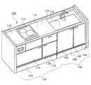
図1は、本実施形態にかかる収納庫用引出取手およびキッチン収納庫用引出が適用されるシステムキッチン100の全体構成を説明する図である。かかるシステムキッチン100は、壁付けのものでもよいし、いわゆる対面式のオープンシステムキッチンでもよい。システムキッチン100の天板110(ワークトップとも称される)は、ステンレス材を用いて形成され、システムキッチン100全体の上面を覆っている。なお、天板110は人工大理石(合成樹脂素材)で形成してもよい。
(System kitchen overall configuration)
FIG. 1 is a diagram illustrating the overall configuration of a
天板110には、組み込み式に取り付けられたIHクッキングヒーター112、調理スペース114、天板110に一体形成されたシンク116、および準備スペース118が設けられる。
The
天板110の下は、IHクッキングヒーター112本体が設置されているガスキャビネット120と、シンク116が設置されているシンクキャビネット140とに大別される。
Below the
ガスキャビネット120の中央部の下には幅の広い大きな収納庫124が配設され、鍋やボウルなどの比較的大きな調理器具を収納することが可能になっている。同様に、シンクキャビネット140には高い前板を備えた収納庫144が備え付けられている。収納庫144は内部が一つの空間となっていて、大容量の収納庫として使用できる。
Under the central portion of the
そして、収納庫124、144の下部の床近傍には、引出式の足元収納である床面すれすれの足下収納庫126、146が配設されている。足下収納庫126、146それぞれの前板の上部には、取手128、148が取り付けられている。
In the vicinity of the floor at the bottom of the
(キッチン収納庫用引出取手)
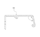
図2は取手128の拡大断面図である。取手128、148(図1参照)の断面形状は共通であるため、ここでは取手128を代表として説明する。取手128は、引出式の足下収納庫126(図1参照)が引き出される方向127に平行な平板状の取手本体200と、取手本体200から連続し観者に角202を向けて屈曲した屈曲部204と、屈曲部204から連続した平板状の把持部206と、を含む。
(Drawer handle for kitchen storage)
FIG. 2 is an enlarged cross-sectional view of the
取手本体200、屈曲部204および把持部206の観者側には、連続した平目ローレット加工が施されている。平目ローレット加工のローレット幅(ピッチ)は、図面からも明らかなように、一定ではなく、屈曲部204に近付くに従って狭くなる。
On the viewer side of the
観者にとって最も近いのは角202を有する屈曲部204であり、角202から離れるほど、観者からも遠くなる。しかし、ローレット幅の広い部分は近く見え、幅の狭い部分は遠く見えるように、遠近感に錯覚を起こさせる。このため、実際には突出している屈曲部204の角が遠く見えるため、突出の程度が緩和されて見えることとなり、擬似的に角度がゆるやかな曲面と認識することができる。
The closest part to the viewer is a
すなわち、取手128、148は実際には曲面を有してはいないものの、人間の視覚が曲面であるかの如き錯覚に至ることで、把持のし易さなどの機能面と、外観の柔らかさという、双方の要求を満たすことが可能となる。
That is, although the
屈曲部204の角202の角度θは、90°である。ただし、角度θは、90°〜105°の角度を成していることが好ましい。図3は他の取手の実施形態を示す図である。この取手328は、角度θを上記の範囲で鈍角にしたものである。角202における角度が大きくなりすぎると、取手128と収納庫124(図1参照)の間に隙間が形成されてしまうためである。一方、鋭角になると把持部206の前面が視界に入りにくくなり、本実施形態の目的である丸みをもった柔らかい外観の視覚効果が減退してしまうからである。
The angle θ of the
図2の取手本体200中心部にある断面が略円形の部位210と、取手本体200の屈曲部204にある断面が略円形の部位212と、把持部206の先端かつ最下端に位置する断面が略円形の部位214は、取手128を足下収納庫126(図1参照)に取り付けた後、取手128の長手方向両端にベースキャップ228(図3を参照)を取り付けるための部位である。
A
取手本体200の把持部206と反対側には、足下収納庫126の前板の背面に取手128を固定するための板状の取付部230およびネジ穴232が設けられている。すなわち取手128は、足下収納庫126の前板の背面から上部を回り込んで前面側に突出するように配置されている。
On the opposite side of the
図4は取手128の三面図であって図3(a)は平面図、図3(b)は側面図、図3(c)は正面図、図3(d)は図3(b)のベースキャップ228を取り外した状態を示す側面図である。図5は取手の端部の拡大斜視図である。至近距離から見ると、ローレット幅には差があり、取手本体200または把持部206から屈曲部204に近付くに従って、狭くなることが分かる。
FIG. 4 is a three-side view of the
図6は足下収納庫126、146の拡大斜視図である。足下収納庫126は開いた状態である。このように足下収納庫126が開かれると、取手128は前述の通り、ローレット幅が変化する平目ローレット加工の遠近法の視覚効果により、角ばった形状(端部にて顕著)でありながら、表面は丸みを感じさせる外観を有している。
FIG. 6 is an enlarged perspective view of the
一方、足下収納庫146は収納された状態であるので、丸みを感じさせる外観は出現していないが、閉じた状態において、取手148の把持部206は、収納庫144と面一になっていて、収まりのよいデザインになっている。
On the other hand, since the
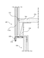
図6はガスキャビネット120の足下収納庫126付近の拡大断面図である。収納庫の前板124aは、収納庫124の前面に張られている板である。収納庫の前板124aは、パッキン252によって収納庫底板256との隙間を封止している。
FIG. 6 is an enlarged cross-sectional view of the vicinity of the
幕板258と収納庫の前板124aの間には若干のクリアランス264があり、ここに塵芥や害虫が入り込んでしまうことが多い。取手128は、上述のように、丸みを帯びた外観を有するが、取手本体200は、本来、平板状に伸びていて、しかも、屈曲部204(図2または図5参照)の曲率半径が小さく、急峻に屈曲しているために、このクリアランス264の下面を覆い、クリアランス264に塵芥等が入らない機能的な効果がある。このように、機能的な側面から、屈曲部204の曲率半径は、非常に小さいものであるが、既に説明したローレット加工の効果により、大きな曲率半径に見えるという視覚的な効果が得られている。
There is a
取手128、148は、押出成形によって製造可能である。これは、ローレット加工された断面形状が一様だからである。押出成形可能であるため、長尺で同一の断面形状を有する材料を加工する際、安価に製造することができる。
The
本実施形態では、取手128、148に使用されている材質は、アルミ合金であるが、他の金属を用いてもよい。
In this embodiment, the material used for the
本実施形態における取手128、148は、足下収納庫126、146に取り付けられたものであるが、他の収納庫に取り付けてもよい。また、設計上曲面が使えない箇所に本実施形態を応用してもよい。さらに、キッチンに限らず、前板の上部に取手を有する引出を備えた収納庫に本発明を適用することができる。
The
以上、添付図面を参照しながら本発明の好適な実施形態について説明したが、本発明は係る例に限定されないことは言うまでもない。当業者であれば、特許請求の範囲に記載された範疇内において、各種の変更例または修正例に想到し得ることは明らかであり、それらについても当然に本発明の技術的範囲に属するものと了解される。 As mentioned above, although preferred embodiment of this invention was described referring an accompanying drawing, it cannot be overemphasized that this invention is not limited to the example which concerns. It will be apparent to those skilled in the art that various changes and modifications can be made within the scope of the claims, and these are naturally within the technical scope of the present invention. Understood.
本発明は、収納庫用引出取手および収納庫に適用可能である。 The present invention is applicable to storage drawer drawers and storages.
100 …システムキッチン
120 …ガスキャビネット
124、144 …収納庫
126 …足下収納庫
128、148、328 …取手
146 …足下収納庫
200 …取手本体
202 …角
204 …屈曲部
206 …把持部
252 …パッキン
264 …クリアランス
DESCRIPTION OF
Claims (3)
前記取手本体から連続し観者に角を向けて屈曲した屈曲部と、
前記屈曲部から連続した平板状の把持部と、
を含み、
前記取手本体、屈曲部および把持部の観者側には、連続した平目ローレット加工が施されていて、
前記平目ローレット加工のローレット幅は、前記屈曲部に近付くに従って狭くなることを特徴とする収納庫用引出取手。 A plate-like handle body that is attached to the drawer of the storage and is parallel to the direction in which the drawer is pulled out;
A bent part that is continuous from the handle body and bent toward the viewer,
A flat plate-like gripping part continuous from the bent part;
Including
On the viewer side of the handle body, the bent part and the grip part, a continuous flat knurling process is applied,
The drawer handle for storage, wherein the knurl width of the flat knurling process becomes narrower as it approaches the bent portion.
当該引出に取り付けられた、当該引出が引き出される方向に平行な平板状の取手本体と、該取手本体から連続し観者に角を向けて屈曲した屈曲部と、該屈曲部から連続した平板状の把持部とから成る取手を含み、
前記取手本体、屈曲部および把持部の観者側には、連続した平目ローレット加工が施されていて、
前記平目ローレット加工のローレット幅は、前記屈曲部に近付くに従って狭くなることを特徴とする収納庫。 In the storage with drawers,
A flat handle body attached to the drawer that is parallel to the direction in which the drawer is pulled out, a bent portion that is continuous from the handle body and is bent toward the viewer, and a flat plate shape that is continuous from the bent portion Including a handle consisting of
On the viewer side of the handle body, the bent part and the grip part, a continuous flat knurling process is applied,
The knurl width of the flat knurling process is narrowed as it approaches the bent portion.
Priority Applications (1)
| Application Number | Priority Date | Filing Date | Title |
|---|---|---|---|
| JP2008196352A JP5366466B2 (en) | 2008-07-30 | 2008-07-30 | Storage drawer drawer and storage |
Applications Claiming Priority (1)
| Application Number | Priority Date | Filing Date | Title |
|---|---|---|---|
| JP2008196352A JP5366466B2 (en) | 2008-07-30 | 2008-07-30 | Storage drawer drawer and storage |
Publications (2)
| Publication Number | Publication Date |
|---|---|
| JP2010029526A true JP2010029526A (en) | 2010-02-12 |
| JP5366466B2 JP5366466B2 (en) | 2013-12-11 |
Family
ID=41734725
Family Applications (1)
| Application Number | Title | Priority Date | Filing Date |
|---|---|---|---|
| JP2008196352A Expired - Fee Related JP5366466B2 (en) | 2008-07-30 | 2008-07-30 | Storage drawer drawer and storage |
Country Status (1)
| Country | Link |
|---|---|
| JP (1) | JP5366466B2 (en) |
Cited By (3)
| Publication number | Priority date | Publication date | Assignee | Title |
|---|---|---|---|---|
| IT201600115551A1 (en) * | 2016-11-16 | 2018-05-16 | Faer Ambienti S P A | HANDLE FOR FURNITURE DOORS. |
| JP2020110357A (en) * | 2019-01-11 | 2020-07-27 | オムロンヘルスケア株式会社 | Biological sound measuring device |
| KR20210158312A (en) * | 2020-06-23 | 2021-12-30 | 주식회사 에스와이산업 | Non insert type knob for a furniture drawer |
Citations (4)
| Publication number | Priority date | Publication date | Assignee | Title |
|---|---|---|---|---|
| JP2002017490A (en) * | 2000-07-07 | 2002-01-22 | Nakabayashi Co Ltd | Index structure of drawer |
| JP2003321954A (en) * | 2002-04-30 | 2003-11-14 | Shimodaira:Kk | Pull |
| JP2004232284A (en) * | 2003-01-29 | 2004-08-19 | Yamaha Livingtec Corp | Door handle structure |
| JP2005076278A (en) * | 2003-08-29 | 2005-03-24 | Atom Livin Tech Co Ltd | Pull handle |
-
2008
- 2008-07-30 JP JP2008196352A patent/JP5366466B2/en not_active Expired - Fee Related
Patent Citations (4)
| Publication number | Priority date | Publication date | Assignee | Title |
|---|---|---|---|---|
| JP2002017490A (en) * | 2000-07-07 | 2002-01-22 | Nakabayashi Co Ltd | Index structure of drawer |
| JP2003321954A (en) * | 2002-04-30 | 2003-11-14 | Shimodaira:Kk | Pull |
| JP2004232284A (en) * | 2003-01-29 | 2004-08-19 | Yamaha Livingtec Corp | Door handle structure |
| JP2005076278A (en) * | 2003-08-29 | 2005-03-24 | Atom Livin Tech Co Ltd | Pull handle |
Cited By (6)
| Publication number | Priority date | Publication date | Assignee | Title |
|---|---|---|---|---|
| IT201600115551A1 (en) * | 2016-11-16 | 2018-05-16 | Faer Ambienti S P A | HANDLE FOR FURNITURE DOORS. |
| JP2020110357A (en) * | 2019-01-11 | 2020-07-27 | オムロンヘルスケア株式会社 | Biological sound measuring device |
| JP7230516B2 (en) | 2019-01-11 | 2023-03-01 | オムロンヘルスケア株式会社 | Body sound measuring device |
| US11751839B2 (en) | 2019-01-11 | 2023-09-12 | Omron Healthcare Co., Ltd. | Biological sound measurement device |
| KR20210158312A (en) * | 2020-06-23 | 2021-12-30 | 주식회사 에스와이산업 | Non insert type knob for a furniture drawer |
| KR102546411B1 (en) | 2020-06-23 | 2023-06-23 | (주)에스와이산업 | Non insert type knob for a furniture drawer |
Also Published As
| Publication number | Publication date |
|---|---|
| JP5366466B2 (en) | 2013-12-11 |
Similar Documents
| Publication | Publication Date | Title |
|---|---|---|
| USD913753S1 (en) | Spice rack | |
| USD556061S1 (en) | Thermostat with touch screen | |
| USD567060S1 (en) | Appliance knob | |
| USD582720S1 (en) | Knob for cooking utensil | |
| USD521286S1 (en) | Shelf with lighting grid | |
| USD577539S1 (en) | Steam knob for cooking utensil | |
| JP5366466B2 (en) | Storage drawer drawer and storage | |
| JP2006334240A (en) | Kitchen counter | |
| KR101886927B1 (en) | Shelf for hanging cabinet for kitchen cabinet drawer | |
| USD523689S1 (en) | Knob for cooking utensil | |
| JP2006341004A (en) | Drawer-type drying cabinet | |
| USD504585S1 (en) | Ceiling rack for pots, pans and utensils | |
| JP6426671B2 (en) | System kitchen | |
| JP2010148788A (en) | Frying pan rack | |
| USD513684S1 (en) | Backguard/control panel for a cooking appliance | |
| USD488342S1 (en) | Pancake and egg cooking appliance | |
| TWI619460B (en) | Removable device for holding a cooking utensil | |
| USD528874S1 (en) | Set of kitchen utensils on a support | |
| KR200392546Y1 (en) | door for kitchen furniture | |
| USD547603S1 (en) | Support for cooking utensil | |
| USD570183S1 (en) | Cabinet knob | |
| JP2007252700A (en) | Structure of front side of dishwasher | |
| JP3225175U (en) | Cookware set | |
| USD511935S1 (en) | Backguard/control panel for a cooking appliance | |
| KR200271107Y1 (en) | A metal appliance for knob of furniture |
Legal Events
| Date | Code | Title | Description |
|---|---|---|---|
| A621 | Written request for application examination |
Free format text: JAPANESE INTERMEDIATE CODE: A621 Effective date: 20110223 |
|
| A977 | Report on retrieval |
Free format text: JAPANESE INTERMEDIATE CODE: A971007 Effective date: 20121001 |
|
| A131 | Notification of reasons for refusal |
Free format text: JAPANESE INTERMEDIATE CODE: A131 Effective date: 20121106 |
|
| A521 | Written amendment |
Free format text: JAPANESE INTERMEDIATE CODE: A523 Effective date: 20121204 |
|
| TRDD | Decision of grant or rejection written | ||
| A01 | Written decision to grant a patent or to grant a registration (utility model) |
Free format text: JAPANESE INTERMEDIATE CODE: A01 Effective date: 20130910 |
|
| A61 | First payment of annual fees (during grant procedure) |
Free format text: JAPANESE INTERMEDIATE CODE: A61 Effective date: 20130910 |
|
| R150 | Certificate of patent or registration of utility model |
Free format text: JAPANESE INTERMEDIATE CODE: R150 |
|
| R250 | Receipt of annual fees |
Free format text: JAPANESE INTERMEDIATE CODE: R250 |
|
| R250 | Receipt of annual fees |
Free format text: JAPANESE INTERMEDIATE CODE: R250 |
|
| LAPS | Cancellation because of no payment of annual fees |