KR20080098602A - An internal combustion engine - Google Patents
An internal combustion engine Download PDFInfo
- Publication number
- KR20080098602A KR20080098602A KR1020087019091A KR20087019091A KR20080098602A KR 20080098602 A KR20080098602 A KR 20080098602A KR 1020087019091 A KR1020087019091 A KR 1020087019091A KR 20087019091 A KR20087019091 A KR 20087019091A KR 20080098602 A KR20080098602 A KR 20080098602A
- Authority
- KR
- South Korea
- Prior art keywords
- combustion chamber
- fuel
- internal combustion
- combustion engine
- engine according
- Prior art date
- Legal status (The legal status is an assumption and is not a legal conclusion. Google has not performed a legal analysis and makes no representation as to the accuracy of the status listed.)
- Withdrawn
Links
- 238000002485 combustion reaction Methods 0.000 title claims abstract description 110
- 238000000034 method Methods 0.000 claims abstract description 8
- 239000000446 fuel Substances 0.000 claims description 99
- 230000006835 compression Effects 0.000 claims description 25
- 238000007906 compression Methods 0.000 claims description 25
- 238000002347 injection Methods 0.000 claims description 16
- 239000007924 injection Substances 0.000 claims description 16
- 239000007789 gas Substances 0.000 description 8
- 239000010720 hydraulic oil Substances 0.000 description 3
- 239000000203 mixture Substances 0.000 description 2
- 238000007789 sealing Methods 0.000 description 2
- 239000007921 spray Substances 0.000 description 2
- 239000004215 Carbon black (E152) Substances 0.000 description 1
- 241001621399 Lampris Species 0.000 description 1
- QVGXLLKOCUKJST-UHFFFAOYSA-N atomic oxygen Chemical compound [O] QVGXLLKOCUKJST-UHFFFAOYSA-N 0.000 description 1
- 230000008020 evaporation Effects 0.000 description 1
- 238000001704 evaporation Methods 0.000 description 1
- 238000004880 explosion Methods 0.000 description 1
- 229930195733 hydrocarbon Natural products 0.000 description 1
- 150000002430 hydrocarbons Chemical class 0.000 description 1
- 239000003921 oil Substances 0.000 description 1
- 239000001301 oxygen Substances 0.000 description 1
- 229910052760 oxygen Inorganic materials 0.000 description 1
- 230000002093 peripheral effect Effects 0.000 description 1
- 238000002791 soaking Methods 0.000 description 1
- 238000003466 welding Methods 0.000 description 1
Images


Classifications
-
- F—MECHANICAL ENGINEERING; LIGHTING; HEATING; WEAPONS; BLASTING
- F02—COMBUSTION ENGINES; HOT-GAS OR COMBUSTION-PRODUCT ENGINE PLANTS
- F02B—INTERNAL-COMBUSTION PISTON ENGINES; COMBUSTION ENGINES IN GENERAL
- F02B19/00—Engines characterised by precombustion chambers
- F02B19/08—Engines characterised by precombustion chambers the chamber being of air-swirl type
-
- F—MECHANICAL ENGINEERING; LIGHTING; HEATING; WEAPONS; BLASTING
- F02—COMBUSTION ENGINES; HOT-GAS OR COMBUSTION-PRODUCT ENGINE PLANTS
- F02B—INTERNAL-COMBUSTION PISTON ENGINES; COMBUSTION ENGINES IN GENERAL
- F02B19/00—Engines characterised by precombustion chambers
- F02B19/10—Engines characterised by precombustion chambers with fuel introduced partly into pre-combustion chamber, and partly into cylinder
-
- F—MECHANICAL ENGINEERING; LIGHTING; HEATING; WEAPONS; BLASTING
- F02—COMBUSTION ENGINES; HOT-GAS OR COMBUSTION-PRODUCT ENGINE PLANTS
- F02M—SUPPLYING COMBUSTION ENGINES IN GENERAL WITH COMBUSTIBLE MIXTURES OR CONSTITUENTS THEREOF
- F02M41/00—Fuel-injection apparatus with two or more injectors fed from a common pressure-source sequentially by means of a distributor
-
- Y—GENERAL TAGGING OF NEW TECHNOLOGICAL DEVELOPMENTS; GENERAL TAGGING OF CROSS-SECTIONAL TECHNOLOGIES SPANNING OVER SEVERAL SECTIONS OF THE IPC; TECHNICAL SUBJECTS COVERED BY FORMER USPC CROSS-REFERENCE ART COLLECTIONS [XRACs] AND DIGESTS
- Y02—TECHNOLOGIES OR APPLICATIONS FOR MITIGATION OR ADAPTATION AGAINST CLIMATE CHANGE
- Y02T—CLIMATE CHANGE MITIGATION TECHNOLOGIES RELATED TO TRANSPORTATION
- Y02T10/00—Road transport of goods or passengers
- Y02T10/10—Internal combustion engine [ICE] based vehicles
- Y02T10/12—Improving ICE efficiencies
Landscapes
- Engineering & Computer Science (AREA)
- Chemical & Material Sciences (AREA)
- Combustion & Propulsion (AREA)
- Mechanical Engineering (AREA)
- General Engineering & Computer Science (AREA)
- Combustion Methods Of Internal-Combustion Engines (AREA)
- Fuel-Injection Apparatus (AREA)
Abstract
본 발명은 4행정이나 2행정 사이클로 작동하는 불꽃점화 왕복 내연기관에 관한 것으로, 구체적으로는 층상급기법(stratified charge method)을 이용한 린번 스파크점화엔진에 관한 것이다. The present invention relates to a spark-ignition reciprocating internal combustion engine operating in a four-stroke or two-stroke cycle, and more particularly, to a lean burn spark ignition engine using the stratified charge method.
Description
본 발명은 4행정이나 2행정 사이클로 작동하는 불꽃점화 왕복 내연기관에 관한 것으로, 구체적으로는 층상급기법(stratified charge method)을 이용한 린번 스파크점화엔진에 관한 것이다. The present invention relates to a spark-ignition reciprocating internal combustion engine operating in a four-stroke or two-stroke cycle, and more particularly, to a lean burn spark ignition engine using the stratified charge method.
이런 엔진은 부분부하 상태, 심지어는 부분부하 상태에서 열효율을 더 높이기 위해 공기흡입을 조절하지 않는 공회전 상태에서도 동작할 수 있다. These engines can operate at idle, even at partial loads, even when the air intake is not controlled to increase thermal efficiency.
본 발명은 자동차와 모터사이클에 사용할 수 있고, 연료를 크게 절감할 수 있다. 본 발명의 엔진은 압축비가 일정한 경우나 가변적인 경우에 적용할 수 있다. The present invention can be used in automobiles and motorcycles, and can greatly reduce fuel. The engine of the present invention can be applied to a case where the compression ratio is constant or variable.
본 발명은 특히 WO 2005/052335에 소개된 내연기관에 관련된다.The present invention relates in particular to the internal combustion engine introduced in WO 2005/052335.
따라서, 본 발명은 Therefore, the present invention
실린더; 실린더 안에서 왕복운동하는 피스톤; 실린더와 연결된 공기흡입수단; 실린더와 연결된 배기수단; 실린더와 연결되고, 피스톤에서 가까운 일단부와 피스톤에서 먼 타단부를 갖는 간접 연소실; 실린더와 연소실 일단부 사이에 위치하고, 피스톤의 압축행정동안 연소실 안으로 에어젯을 유도하는 급기공; 연소실의 원주방향의 접선 속도성분과 연소실 일단부에서 타단부를 향하는 축방향 속도성분을 갖는 나선형 공기 유동을 연소실 내부에 일으키는 수단; 연소실 안에 설치된 점화수단; 연소실과 연결되고, 상기 에어젯에 연료를 공급하여 점화수단에 도달했을 때 점화가 될 수 있는 혼합기를 형성하기 위한 연료분사수단; 및 연료분사과정과 점화과정을 조절하는 컨트롤러;를 포함하는 내연기관에 있어서:cylinder; A piston reciprocating in the cylinder; Air suction means connected to the cylinder; Exhaust means connected to the cylinder; An indirect combustion chamber connected to the cylinder and having one end close to the piston and the other end remote from the piston; An air supply hole positioned between the cylinder and one end of the combustion chamber and guiding an air jet into the combustion chamber during the compression stroke of the piston; Means for causing a helical air flow in the combustion chamber having a tangential velocity component in the circumferential direction of the combustion chamber and an axial velocity component from one end of the combustion chamber to the other end; Ignition means installed in the combustion chamber; Fuel injection means connected to a combustion chamber for supplying fuel to the air jet to form a mixer that can be ignited when reaching the ignition means; In the internal combustion engine comprising: a controller for controlling the fuel injection process and the ignition process:
상기 나선형 유동의 축방향 속도성분이 연소실의 내부표면에 의해 유도되는 것을 특징으로 하는 내연기관을 제공한다.An axial velocity component of the helical flow is provided by an internal surface of the combustion chamber.
WO2005/052335에 소개된 내연기관에서 연소실내 나선 유동을 일으키는데 필요한 나선 속도성분과 축방향 속도성분의 양쪽 성분을 조절하는 유일한 수단은 급기공(transfer orifice)이었다. 나선운동은 본 발명에 따른 층상운동을 일으키는데 필수적이다. 축방향 성분은 연소실의 축선에 대해 급기공의 축선을 90도까지 기울여 생겼다. 이송공의 접선위치는 원주방향인 선회 속도성분을 결정했다. 그러나, 이런 간단한 디자인에서도 기체 유동에 안정된 축방향 성분을 일으키려면 급기공의 길이가 비교적 길어야 했다. 길이가 지나치면 기체가 고속으로 급기공을 통과할 때 벽면에서 생기는 마찰과 열 손실이 증가하여 엔진의 열효율이 감소한다. 실린더 단부에서 급기공을 기울어지게 형성하면 기다란 타원형 구멍이 생겨 밸브에 사용할 면적이 줄어들고, 결국 엔진의 급기성능에 영향을 준다.In the internal combustion engine introduced in WO2005 / 052335, the only means of controlling both the helical velocity component and the axial velocity component necessary to generate the spiral flow in the combustion chamber was the transfer orifice. Spiral motion is essential to bring about stratified motion according to the invention. The axial component was created by tilting the axis of the air supply hole by 90 degrees with respect to the axis of the combustion chamber. The tangential position of the feed hole determined the rotational speed component in the circumferential direction. However, even in this simple design, the length of the air supply holes had to be relatively long to produce a stable axial component in the gas flow. Excessive lengths increase the friction and heat loss on the wall as the gas passes through the air supply at high speeds, reducing the engine's thermal efficiency. The inclined air supply at the end of the cylinder creates an elongated oval hole, which reduces the area used for the valve, which in turn affects the air supply performance of the engine.
본 발명은 연소실내의 축방향 속도성분을 높여 정확한 나선유동을 일으키는 수단을 제공한다. 이 수단은 앞에서 언급한 모든 단점을 제거한다. 본 발명은 연소실 내부표면을 적절히 구성하여 이를 달성한다. 급기공을 기울어지게 형성할 필요가 없고, 연소실의 일단부의 벽면을 날카롭게 하여 나선 램프를 형성하거나, 연소실의 벽면에 나사홈을 형성하거나, 이 2가지 방법을 병용한다. 어느 방법에서도 내부 표면을 경사지게 형성하여 축방향 속도성분을 일으킨다. 이런 내부표면을 만드는데 신중한 설계가 필요한데, 이는 안정된 연소에 필요한 나선유동의 축방향 속도성분과 접선방향 속도성분 사이의 비율이 중요할 수 있기 때문이다. The present invention provides a means for increasing the axial velocity component in the combustion chamber to produce accurate spiral flow. This means eliminates all the disadvantages mentioned above. The present invention achieves this by properly configuring the combustion chamber internal surface. It is not necessary to form the air supply inclined, and the wall surface of one end of the combustion chamber is sharpened to form a spiral lamp, a screw groove is formed on the wall surface of the combustion chamber, or both methods are used in combination. In either method, the inner surface is inclined to produce an axial velocity component. Careful design is necessary to make these internal surfaces, since the ratio between the axial velocity component and the tangential velocity component of the spiral flow required for stable combustion can be important.
나선 램프는 연소실의 축선 둘레에 비교적 짧은 거리에 걸쳐 형성된 쐐기 모양의 나사 형태를 갖는다. 이런 나선 램프는 축 둘레로 적절한 각도로 뻗되, 270도 이상 뻗는다. 이런 램프의 구조에 대해서는 뒤에 도면을 참조하여 자세히 설명한다.Spiral lamps have the shape of a wedge-shaped screw formed over a relatively short distance around the axis of the combustion chamber. Such spiral lamps extend at appropriate angles around the axis, extending over 270 degrees. The structure of such a lamp will be described in detail later with reference to the drawings.
도 2의 22로 표시한 것과 같이, 즉 나사산이 형성된 볼트와 맞물리는 너트의 암나사와 같은 나사산을 연소실의 벽면에 형성한다. 이런 나사산은 급기공이 연결되는 부근에서 시작해야 한다. 공기가 연소실의 벽면을 따라 선회하기 때문에, 공기의 일부는 이런 나사산을 따라가면서 연소실의 타단부쪽으로 흐른다. 나사산의 크기, 즉 깊이, 형상 및 피치는 설계자가 결정한다. 나사산의 구조는 당업자에게 자명하므로 더이상의 설명은 생략한다.As indicated by 22 in Fig. 2, that is, a thread such as a female thread of a nut engaged with a threaded bolt is formed on the wall surface of the combustion chamber. These threads should start in the vicinity of the supply holes. As the air swirls along the wall of the combustion chamber, part of the air follows this thread and flows to the other end of the combustion chamber. The size of the threads, ie depth, shape and pitch, is determined by the designer. Since the structure of the thread is apparent to those skilled in the art, further description thereof will be omitted.
압축행정동안 급기공을 통해 실린더에서 연소실로 들어가는 공기에 연료가 첨가된다. 단위시간당 공급되는 공기량은 압축행정 초기의 비교적 낮은 값에서 행정 끝의 높은 값까지 비선형적으로 증가하는데, 행정 끝에서 급기공내의 공기의 밀도와 속도는 급격히 상승한다. 그 결과, 압축행정 동안 연료분사수단에서 분사되는 연료량도 점점 증가해야 하는데, 이는 공기와 연료의 혼합기를 연소시키기 위해서이다. 이런 기능을 만족하는 연료분사기는 지금까지 알려진 것이 전혀 없다. 따라서, 본 발명에서는 연소실내 중요한 위치에 연료분사기를 2개 설치한다. 첫번째 연료분사기는 단위시간당 분사되는 연료량이 적은 것으로 연소실의 일단부에서 타단부쪽을 향해 설치하여 압축행정 초기에 연료를 분사하고, 두번째 연료분사기는 연료 분사량이 높은 것으로 급기공에서 나가는 에어젯을 향해 설치되고 압축행정 후반부의 높은 엔진부하에서 연료를 분사하며, 필요하다면 점화가 끝난 뒤에도 연료를 계속 분사한다.Fuel is added to the air entering the combustion chamber from the cylinder through the air supply during the compression stroke. The amount of air supplied per unit time increases nonlinearly from the relatively low value at the beginning of the compression stroke to the high value at the end of the stroke. As a result, the amount of fuel injected from the fuel injection means must also gradually increase during the compression stroke, in order to burn the mixture of air and fuel. No fuel injector that satisfies this feature has ever been known. Therefore, in the present invention, two fuel injectors are provided at important positions in the combustion chamber. The first fuel injector has a small amount of fuel injected per unit time and is installed from one end of the combustion chamber toward the other end to inject fuel at the beginning of the compression stroke. It is installed and injects fuel at the high engine load in the latter part of the compression stroke and, if necessary, continues to inject fuel after the ignition is complete.
본 발명은 또한 이동식 플런저로 연소실의 체적을 조절해 엔진이 작동하는 동안 압축비를 변화시키는 수단도 제공한다. 이런 수단때문에 공기-연료 비가 낮으니 상태에서도 압축비를 높여, 예비점화나 폭발의 위험 없이 부분부하에서 엔진의 열효율을 높일 수 있다. The present invention also provides a means for varying the compression ratio during engine operation by adjusting the volume of the combustion chamber with a movable plunger. This means that the air-fuel ratio is low, increasing the compression ratio even under conditions, increasing the thermal efficiency of the engine at partial load without the risk of pre-ignition or explosion.
여기서 사용된 공기나 기체란 말은 순수한 공기나 연소생성물과 같은 다른 기체, 심지어는 탄화수소 기체를 포함하는 개념이다. 혼합기는 점화를 위해 증발된 연료와 공기가 혼합된 것을 말한다. 희박 혼합기란 엔진에서 사용되는 점화수단으로 직접 점화되지 않는 혼합기를 말한다.The term air or gas as used herein is a concept that includes other gases, such as pure air or combustion products, even hydrocarbon gases. A mixer is a mixture of fuel and air evaporated for ignition. A lean mixer is a mixer that is not directly ignited by the ignition means used in the engine.
BMEP는 실린더에 생기는 실제평균유효압(brake mean effective pressure)을 말한다. 연소실은 간접 연소실로서, 바람직한 것은 중심축에 대해 대칭으로 원통형이나 원추형이 대부분이지만, 다른 형상을 취할 수도 있다. BMEP is the brake mean effective pressure in the cylinder. The combustion chamber is an indirect combustion chamber, most preferably cylindrical or conical in symmetry with respect to the central axis, but may take other shapes.
이하, 첨부 도면들을 참조하여 본 발명에 대해 자세히 설명한다.Hereinafter, the present invention will be described in detail with reference to the accompanying drawings.
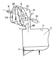
도 1은 WO 2005/052335에 소개된 도면;1 is a view introduced in WO 2005/052335;
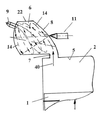
도 2는 에어젯의 축방향 속도성분을 향상시키기 위해 연소실 내부표면을 자세히 보여주는 단면도;2 is a cross-sectional view detailing the interior surface of the combustion chamber to improve the axial velocity component of the airjet;
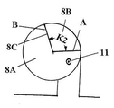
도 3은 연료분사기(11) 입구쪽의 연소실(6)의 일단부의 정면도;3 is a front view of one end of the
도 4는 도 3의 나선램프(8B)를 자세히 도시한 것으로, 스트림라인(14)이 램프를 타고 움직이는 것이 보인다.FIG. 4 shows the
도 5는 도 3~4와 비슷하되 나선 램프가 확장된 상태;5 is similar to FIGS. 3 to 4 but with the spiral lamp expanded;
도 6~7은 도 3과 비슷하되, 나선 램프가 변형된 상태;6 to 7 are similar to FIG. 3, with the spiral lamp deformed;
도 8은 연료분사기가 2개인 경우의 단면도;8 is a sectional view in the case of two fuel injectors;
도 9는 플런저의 유압 동작을 이용해 압축비를 가변적으로 하는 연소실의 단면도;9 is a cross-sectional view of the combustion chamber varying the compression ratio using hydraulic operation of the plunger;
도 10은 플런저의 전기기계식 동작을 이용해 압축비를 가변적으로 하는 연소실의 단면도.10 is a cross-sectional view of the combustion chamber of varying compression ratios using electromechanical operation of the plunger.
도 1의 종래의 구성에서, 연소실(6)의 축을 실린더(2)의 축에 대해 기울이고 또한 연소실(6)의 축에 대해 급기공(7)을 기울어지게 하면 나선운동에 필요한 축방향 속도성분이 유도된다. 본 발명에 의하면, 연소실의 축은 실린더 축에 거의 수직이고, 축방향 속도성분은 연소실 내부의 표면에 의해 유도된다. In the conventional configuration of FIG. 1, when the axis of the
도 1의 구성에서, 피스톤(1)은 압축행정동안 실린더(2)에서 위로 움직인다. 연소실(6)은 급기공(7)을 통해 실린더와 통한다. 하나의 연료분사기(11)에서 분사된 연료는 에어젯(40)을 가로질러 연소실의 타단부(10)에 이를 때에는 연소실의 전 체 직경까지 퍼지며, 타단부에 점화플러그(9)가 위치한다. 도면에서 연소실의 원주면(22)을 회전하는 스트림라인(14)은 나선형을 그린다. 실린더(2)는 기존의 방식대로 흡기밸브 및 배기밸브와 통하고, 연소실(6)은 원통형이며, 점화플러그(9)는 타단부에 위치한다. 급기공(7)은 연소실(6)의 축에 둔각으로 기울어져 연소실의 일단부(8)로 들어가는데, 이런 기울기는 축선방향과 접선방향의 양쪽 성분을 모두 갖는다. 엔진 컨트롤러(도시 안됨)는 연료를 분사할 시기와 기간, 연료의 압력, 점화시기를 결정하는데, 이런 모든 설명은 WO2005/52335에 기재되어 있다.In the configuration of FIG. 1, the
도 2의 구성요소는 많은 부분이 도 1의 구성요소와 같은 기능을 하고 동일한 번호를 부여했으며, 이에 대한 설명은 생략한다. 여기서는 에어젯(40)이 연소실(6)의 축선에 거의 직각으로 연소실에 들어가고 접선 속도성분은 있지만 축방향 속도성분은 없다. 축방향 속도성분은 연소실, 구체적으로는 일단부(8)의 단부벽 내벽면이 기울어진데서 생기고, 따라서 스트림라인(14)도 단부벽의 경사면을 따라간다.Many of the components of FIG. 2 function the same as the components of FIG. 1 and are given the same numbers, and description thereof will be omitted. Here, the
급기공쪽의 일단부의 벽면이 타단부를 향해 경사진 형태의 경우, 급기공(7)에서 가장 멀리 있는 내측면은 급기공보다 타단부에 더 가까울 수 있다. 일반적으로, 급기공쪽의 일단부의 벽면은 일단부 반대쪽을 향해 경사진다. When the wall surface of one end of the air supply side is inclined toward the other end, the inner side surface furthest from the
본 발명의 바람직한 형태에서, 급기공쪽의 일단부의 벽면 형상을 더 복잡하게 하여 나선 램프 형태로 하고, 나선 사이의 피치를 일정하게 하거나 가변적으로 할 수도 있는데, 바람직한 형태는 피치가 점점 증가하는 것이다.In a preferred embodiment of the present invention, the wall shape of one end of the air supply side can be made more complicated to form a spiral lamp, and the pitch between the spirals can be made constant or variable, and the preferred form is that the pitch gradually increases.
도 3~4는 이런 형태의 예를 보여준다. 도 3은 연료분사기(11) 입구쪽의 연소실(6)의 일단부의 정면도로서, 급기공(7)이 보이고, 연소실로 들어가는 에어젯(40) 의 속도벡터도 보인다. 또, 원주방향으로 회전하는 스트림라인(14)도 보인다. 반경선 A는 나선램프(8B)가 평탄 플랫폼(8A)을 출발해 상승하기 시작함을 보여주는데, 플랫폼(8A)은 원형 급기공(7)의 가장자리와 일치한다. 나선램프(8B)는 연소실을 거의 270도 차지하여 라인 B까지 차지하는데, 이 지점은 연소실의 축에 평행한 벽면(8B)이 끝나는 지점으로 나선램프(8B)의 끝 부분을 플랫폼(8A)에 연결하는 지점이다.3-4 show an example of this type. 3 is a front view of one end of the
본 실시예에서 90도로 뻗은 플랫폼(8A)은 다음의 3가지 중요한 기능을 한다. 급기공에서 들어오는 에어젯에 접근하는 것을 허용하여, 급기공 반대쪽에 위치한 두번째 연료분사기(도시 안됨)의 스프레이의 혼입과 첫번째 연료분사기의 출구 역할을 한다. 급기공을 통해 벽면(8C)과 연소실의 주변벽 사이로 들어오는 에어젯은 벽면(8C)에 부딪쳐 방향을 바꾸고, 또한 램프가 벽면(8C)까지 상승한다. In this embodiment, the
도 4는 도 3의 나선램프(8B)를 자세히 도시한 것으로, 스트림라인(14)이 램프를 타고 움직이는 것이 보인다. P는 나선의 피치의 절반으로, 피치는 나선운동의 축방향 성분의 강도를 결정한다. FIG. 4 shows the
도 6~7은 나선램프의 구조를 보여주는데, 각각의 나선램프가 이루는 원호각도는 각각 K1과 K2이다. 도 6의 나선램프(8B)는 B 라인에서 끝나고 그 뒤에 돌출 플랫폼(8E)이 이어진다. 플랫폼(8E)은 축방향 벽면(8C)까지 이어지고, 이 벽면에 플랫폼(8A)이 이어진다. 도 7의 더 짧은 나선램프는 B 라인에서 끝나는데, 그 뒤에는 돌출 플랫폼이 이어지지 않는다. B 라인도 벽면(8C)에 위치하는데, 이 벽면 뒤에는 플랫폼(8A)이 이어진다.6 to 7 show the structure of spiral lamps, and arc angles formed by each spiral lamp are K1 and K2, respectively. The
플랫폼(8A,8B)과 벽면(8C)의 원호 K, 형상 및 크기의 선택은 디자이너에게 달려있다.The choice of arc K, shape and size of the
또, 공기류를 접선방향으로 흐르게 하거나 이 흐름을 강화시키는데 급기공의 위치를 이용하지 않고 연소실의 내측면을 이용하는 것이 바람직할 수도 있다. 이런 구성이 도 5에 도시되었는데, 도 5는 도 2와 비슷하지만 나선램프(8B)가 연소실 둘레로 270도 이상, 거의 310도까지 뻗어 B 라인까지 이어진다.In addition, it may be desirable to use the inner surface of the combustion chamber without using the position of the air supply hole to allow the air flow to flow in a tangential direction or to enhance the flow. This configuration is shown in FIG. 5, which is similar to FIG. 2, but
본 실시예에서 벽면(8C)은 270도를 약간 지나서 위치하고, 나선램프(8B)의 나머지 부분 밑으로 공간(C)을 남겨둔다. 이런 공간의 천정은 나선램프의 밑면으로서 천이공(7)을 지나 연소실까지 이어진다. 이런 천정 밑에 있는 휘어진 벽면(8D)은 연소실의 중심축에 가까이 위치하면서 접선 방향의 에어젯을 연소실의 주변인 공간(8A)쪽으로 돌리는데 이용된다.In this embodiment the
첫번째 연료분사구(11)는 점화플러그가 위치한 연소실 단부에 분무연료가 도달할 수 있도록 플랫폼(8A)에 위치한다. 연료분사구로 들어온 연료는 휘어져, 나선램프(8B)가 시작하는 반경선 A를 지난다. 휘어진 벽면(8D)는 곡면형이거나 평면형이거나 곡면과 평면이 조합된 형태로서, 나선램프(8B)의 끝에서 천정을 지나거나, 나선램프가 끝나는 B 라인 지점에서 벽면(8D)이 끝날 수도 있다.The first
도 8은 피스톤(1)이 행정을 끝내기 전에 대략 30도의 크랭크 각도에 있을 때의 엔진을 보여주는 단면도이다. 연소실에는 2개의 연료분사기가 있는데, 이들 2개의 연료분사기가 연료를 분사한다. 첫번째 연료분사기(11)는 연소실의 타단부를 향하고 있으며, 급기공(7)을 나온 에어젯의 흐름을 가로질러 연료를 분사한다. 두번 째 연료분사기(111)는 급기공을 나온 에어젯의 반대 방향으로 연료를 분사한다. 도면에서 피스톤(1) 위에 남아있는 공간(V1)의 체적과 연소실의 내부공간(V6)의 체적이 같아서, 양쪽 공간에 들어있는 공기량은 거의 같다. 연료분사기(111)가 이때까지 동작하지 않으면, 피스톤 위의 공간(V1)에 아무런 연료가 없고 연소실 내부공간(V6)의 공기에는 연료가 들어있는데, 특히 이 연료는 나선형 기체운동에 의해 점화플러그 부근까지 도달한다. 이때 점화플러그가 작동하면 공간(V6)내 혼합기가 타오르되 실린더에 원래 들어있던 공기의 거의 절반은 연소과정에 사용된다.8 is a sectional view showing the engine when the
본 실시예에서, 첫번째 연료분사기(11)는 압축행정인 180도의 크랭크각도중에서 150도의 크랭크각도에 걸쳐 공기의 절반에 연료를 공급한다. 공기중의 모든 산소를 연소에 사용해야 한다면, 나머지 30도의 크랭크각도 동안에 두번째 연료분사기(111)는 동일한 양의 연료를 필요로 한다. 이런 크랭크각도에 걸쳐 단위시간당 배출되는 평균 연료량은 첫번째 연료분사기(11)가 배출하는 양의 5배 정도 되어야 한다. In this embodiment, the
첫번째 연료분사기(11)가 엔진 관리시스템의 제어하에 압축행정동안 연료량을 5배까지 증가시킬 수만 있으면, 두번째 연료분사기가 불필요하겠지만, 이렇게 반응할 수 있는 가변유량형 연료분사기는 현재 없는 것으로 알고 있다. As long as the
첫번째 연료분사기(11)가 엔진을 정지상태에서 중간 BMEP 상태로 작동시킬 수 있지만, 더 큰 출력을 내려면 두번째 연료분사기(111)가 동일 엔진사이클 동안에 연료를 공급해야 한다. 두번째 연료분사기에서 분사한 연료는 최고의 유량으로 연소실에 들어가는 공기와 섞이는데 이는 급기공내의 공기 속도와 밀도가 압축행정 의 끝에서 가장 높기 때문이다. 이렇게 되면 연료분사기(111)에 의해 공기중에 분사된 연료의 급속증발이 촉진된다. 이렇게 형성된 혼합기는 연료분사기(11)에서 공급된 혼합기내에서 점화플러그(9)의 불꽃에 의해 점화된다. The
2개의 연료분사기를 사용하는 것이 지나치다고 할 수 있지만, 개솔린기관의 열효율을 디젤기관급으로 올리는데는 아주 작은 비용이라 할 것이다.It can be said that using two fuel injectors is excessive, but it is a small cost to raise the gas efficiency of gasoline engine to diesel engine class.
디젤기관의 연소과정과 비슷하게 연료를 분사하자마자 연소시키도록 압축행정동안 연료를 분사하도록 두번째 연료분사기(111)를 제어할 수 있다.Similar to the combustion process of the diesel engine, the
또, 두번째 연료분사기(111)가 급기공 맞은편에 위치하기 때문에, 엔진의 작동상태에 따라서는 두번째 연료분사기(111)가 직접 실린더(2)의 급기공(7)에 연료를 분사하는 것이 유리할 수도 있다. 구체적으로는 흡입행정중이나 압축행정의 초기에 에어젯이 약할 때 하면 좋다. 이 경우, 압축행정동안 연소실로 들어간 에어젯에 연료가 혼합될 수 있다.In addition, since the
이제 엔진의 동작에 대해 설명한다. 공회전시 첫번째 연료분사기(11)는 미리 소량의 연료를 압축행정 동안 분사한 다음 정지한다. 이때의 에어젯의 속도는 낮으며, 연료는 타단부(10)에 도달해 모인다. 이 연료는 연소실의 타단부(10)에 도달한 공기와 섞여 혼합기로 되고, 공기의 나선 운동에 의해 혼합기는 계속 타단부(10) 부근에 머무른다. 혼합기를 점화시키면 타오르고 언쓰로틀드 공회전(unthrotled idling)이 가능하다Now describe the operation of the engine. At idle, the
공회전과 중간범위 사이의 BMEP를 위해 연료분사기(11)의 연료분사시간은 늘어나지만, 최적의 연소를 위해서 분사 개시와 정지 타이밍을 조절한다. 두번째 연 료분사기(111)는 그동안 정지상태를 유지한다.The fuel injection time of the
BMEP 출력을 높이기 위해, 첫번째 연료분사기(11)가 작동되고 나서 에어젯 속도와 기체밀도가 급격히 상승할 때 압축행정의 끝에 두번째 연료분사기(111)를 작동시킨다. 점화플러그(9)가 점화한 뒤 두번째 연료분사기(111)에서 연료를 분사하여 형성된 혼합기에 불꽃이 닿는데, 이런 두번째 연료분사에 의해 연료가 연료가 연소되는 동안 연료가 균일하게 분사된다. 설계사양에 따라서는 두번째 점화플러그(9B)를 연소실의 일단부(8) 부근에 설치하여 연료의 점화를 보조하기도 한다.In order to increase the BMEP output, the
연료분사기로 들어가는 배관의 연료 압력을 조절하여 엔진의 속도변화에 맞게 연료분사량을 조절할 수 있는데, 이는 당 분야의 일반적 관행이다.By adjusting the fuel pressure in the pipes entering the fuel injector, the fuel injection amount can be adjusted according to the engine speed change, which is a common practice in the art.
도 9~10은 본 발명의 가변형 압축특성을 보여준다. 전술한 바와 같이, 공기는 나선 형태로 연소실(6)에 들어간다.9 to 10 show the variable compression characteristics of the present invention. As described above, air enters the
가변형 압축비를 위해, 원통형 연소실(6)의 타단부쪽에 플런저(100) 형태로 이동식 벽면을 마련한다. 플런저의 원주에는 링 모양으로 고온에 견딜 수 있는 다중시일(101)을 설치한다. 연소실 외벽은 시일을 보호하기 위해 냉각할 수 있다. 도면에서 가장 안쪽으로 플런저가 들어가면 압축비가 최고로 높아지고, 돌기(102)에 의해 플런저(100)가 더이상 움직이지 못하는데, 이 돌기는 밀봉기능을 강화하기도 한다. For the variable compression ratio, a movable wall surface in the form of a
도 9에서 플런저(100) 뒷쪽의 공간(107)은 오일과 같은 유압유로 채워지는데, 이런 유압유는 파이프(115)를 통해 공급된다. 필요하다면 압축기체를 사용할 수 있고, 이 경우 적당한 압축기체원을 배치할 수 있다. 유압유는 펌프에 의해 실 린더 최고 압력을 넘는 압력까지 압축된다. In FIG. 9 the
도 9에서는 점화플러그(9)를 2군데 설치했다. 9A 위치의 점화플러그는 튜브(109)로 둘러싸이는데, 이 튜브는 용접과 같은 방식으로 플런저에 부착되는 한편 플런자와 함께 움직이기 위해 자체 시일(110)도 필요하다. In FIG. 9, two
9B 위치의 점화플러그는 플런저(100)가 가장 안쪽에 있을 때 플런저의 정면 부근에 배치하여, 희박연소상태에서도 점화가 가능하도록 한다. 공회전이나 저부하 상태에서 분사된 연료로 점화플러그가 적셔지는 것을 최소화하기 위해 양쪽 점화플러그 모두 작은 구멍을 통해 연소실과 통하는 점화공간 안에 배치했지만, 점화플러그에 의한 점화만 보장된다면 이런 배치가 필수적인 것은 아니다.The spark plug in the 9B position is disposed near the front of the plunger when the
도 9의 플런저 위치는 시동상태나 저부하 상태를 위해 고압 위치에 있는 것이지만, 연료공급이 증가하면 유압유를 공간(107)에서 배출하여 최고점 실린더 압력에 의해 플런저를 저압위치로 이동시킬 수 있다. 이런 배출작용은 실린더의 최고점 압력을 원하는 값으로 제한하는 감압밸브에 의해 조절된다.Although the plunger position of FIG. 9 is in the high pressure position for the starting state or the low load state, when the fuel supply is increased, the hydraulic oil can be discharged from the
도 10은 플런저(100)의 위치를 조절하는 기계적 수단을 보여준다. 플런저는 축(108)에 고정되고, 축(108)은 나사로 고정되며, 너트(111)가 케이스에 설치되는데, 너트는 회전하면서 플런저의 직선운동을 일으킨다. 이런 회전은 워엄(113)과 기어(112)의 구성에 의해 이루어지는데, 워엄은 스테핑모터와 같은 전동기로 회전된다. 이런 방법으로 플런저의 위치를 보다 정확히 제어할 수 있지만, 다기통기관의 유압장치와 비교해 하드웨어가 더 필요할 수도 있다.10 shows the mechanical means for adjusting the position of the
변동 압축비 기능은 4행정 기관과 2행정 기관 모두에 이용될 수 있고, 높은 BMEP 동작에서 최고점 실린더 압력을 완화시킨다.The variable compression ratio function can be used for both four-stroke engines and two-stroke engines, relieving peak cylinder pressure at high BMEP operation.
Claims (13)
Applications Claiming Priority (6)
| Application Number | Priority Date | Filing Date | Title |
|---|---|---|---|
| GBGB0600301.6A GB0600301D0 (en) | 2006-01-09 | 2006-01-09 | Internal combustion engine |
| GB0600301.6 | 2006-01-09 | ||
| GB0600843.7 | 2006-01-16 | ||
| GB0600843A GB0600843D0 (en) | 2006-01-16 | 2006-01-16 | Internal combustion engine |
| GB0609721A GB0609721D0 (en) | 2006-05-17 | 2006-05-17 | Internal combustion engine |
| GB0609721.6 | 2006-05-17 |
Publications (1)
| Publication Number | Publication Date |
|---|---|
| KR20080098602A true KR20080098602A (en) | 2008-11-11 |
Family
ID=37944991
Family Applications (1)
| Application Number | Title | Priority Date | Filing Date |
|---|---|---|---|
| KR1020087019091A Withdrawn KR20080098602A (en) | 2006-01-09 | 2006-12-21 | An internal combustion engine |
Country Status (6)
| Country | Link |
|---|---|
| EP (1) | EP1971760B1 (en) |
| JP (1) | JP2009522500A (en) |
| KR (1) | KR20080098602A (en) |
| BR (1) | BRPI0620970A2 (en) |
| CA (1) | CA2636485A1 (en) |
| WO (1) | WO2007080366A1 (en) |
Families Citing this family (3)
| Publication number | Priority date | Publication date | Assignee | Title |
|---|---|---|---|---|
| WO2011027140A1 (en) | 2009-09-02 | 2011-03-10 | Dan Merritt | Internal combustion engine |
| GB201520221D0 (en) * | 2015-11-17 | 2015-12-30 | Merritt Dan | Internal combustion engine |
| CN110234854A (en) * | 2016-10-04 | 2019-09-13 | 莫托丹有限公司 | Spark-ignited internal combustion engine |
Family Cites Families (12)
| Publication number | Priority date | Publication date | Assignee | Title |
|---|---|---|---|---|
| GB421275A (en) * | 1933-05-15 | 1934-12-17 | Harry R Ricardo | Improvements in or relating to internal combustion engines of the liquid fuel injection type |
| GB479861A (en) * | 1935-08-12 | 1938-02-14 | Walter Boxan | Improvements in and relating to compression ignition oil engines |
| US2855907A (en) * | 1954-03-20 | 1958-10-14 | Maschf Augsburg Nuernberg Ag | Internal combustion engine system |
| JPS57131821A (en) * | 1981-02-09 | 1982-08-14 | Daihatsu Motor Co Ltd | Vortex chamber type diesel engine |
| JPS5923030A (en) * | 1982-07-28 | 1984-02-06 | Fuji Heavy Ind Ltd | Structure of combustion chamber of internal combustion engine |
| JPH03294620A (en) * | 1990-04-09 | 1991-12-25 | Kubota Corp | Diesel engine swirl combustion chamber |
| JPH0913971A (en) * | 1995-06-26 | 1997-01-14 | Nissan Diesel Motor Co Ltd | Structure for nozzle hole of combustion chamber of swirl chamber type diesel engine |
| WO1999042718A1 (en) * | 1998-02-23 | 1999-08-26 | Cummins Engine Company, Inc. | Premixed charge compression ignition engine with optimal combustion control |
| KR100899557B1 (en) * | 2000-03-09 | 2009-05-27 | 마이클 패트릭 딕손 | An autoignition engine |
| US20040112329A1 (en) * | 2002-12-17 | 2004-06-17 | Coleman Gerald N. | Low emissions compression ignited engine technology |
| EP1692376B8 (en) * | 2003-11-19 | 2008-07-16 | Musi Engines Limited | Internal combustion engine |
| JP2005256734A (en) * | 2004-03-11 | 2005-09-22 | Fuji Heavy Ind Ltd | In-cylinder injection engine |
-
2006
- 2006-12-21 CA CA002636485A patent/CA2636485A1/en not_active Abandoned
- 2006-12-21 BR BRPI0620970-0A patent/BRPI0620970A2/en not_active IP Right Cessation
- 2006-12-21 KR KR1020087019091A patent/KR20080098602A/en not_active Withdrawn
- 2006-12-21 JP JP2008549053A patent/JP2009522500A/en active Pending
- 2006-12-21 EP EP06820609.3A patent/EP1971760B1/en not_active Not-in-force
- 2006-12-21 WO PCT/GB2006/004840 patent/WO2007080366A1/en not_active Ceased
Also Published As
| Publication number | Publication date |
|---|---|
| EP1971760A1 (en) | 2008-09-24 |
| WO2007080366A1 (en) | 2007-07-19 |
| JP2009522500A (en) | 2009-06-11 |
| EP1971760B1 (en) | 2013-07-10 |
| BRPI0620970A2 (en) | 2011-11-29 |
| CA2636485A1 (en) | 2007-07-19 |
Similar Documents
| Publication | Publication Date | Title |
|---|---|---|
| RU2719254C2 (en) | Ignition system with prechamber for engine (versions) and method of engine operation | |
| RU2136918C1 (en) | Internal combustion engine and method of its operation | |
| EP3232040B1 (en) | Control system of internal combustion engine | |
| JP4100401B2 (en) | Internal combustion engine | |
| US6619254B2 (en) | Method for operating an internal combustion engine operated with a self-ignitable fuel | |
| US5373820A (en) | Cylinder fuel injection type two-cycle engine | |
| CN1101518C (en) | Combined cycle engine | |
| US9194288B2 (en) | High swirl engine | |
| US5009207A (en) | Internal combustion engine | |
| US7387103B2 (en) | Internal combustion engine | |
| JP2007511707A (en) | Internal combustion engine | |
| JP4238682B2 (en) | A two-cycle internal combustion engine capable of self-ignition operation in which air-fuel mixture is compressed and self-ignited | |
| KR20080098602A (en) | An internal combustion engine | |
| RU2468220C2 (en) | Internal combustion engine | |
| GB2218153A (en) | Internal combustion engine | |
| CN101346536B (en) | Internal combustion engine | |
| RU2344299C1 (en) | Two-stroke gasoline engine with direct injection of fuel and electronic control system | |
| KR20180092992A (en) | Internal combustion engine | |
| WO2003008776A2 (en) | Dual fuel source diesel engine | |
| RU2403412C2 (en) | Internal combustion engine | |
| JP2008546953A (en) | Combustion engine | |
| RU2406852C2 (en) | Ice cylinder head | |
| WO2021136987A1 (en) | Rotational fuel injector | |
| US20070204599A1 (en) | Disi injection timing strategy | |
| KR20170035333A (en) | 2 Stroke 1 Cycle Engine with External Compressed Air Supplying System |
Legal Events
| Date | Code | Title | Description |
|---|---|---|---|
| PA0105 | International application |
Patent event date: 20080804 Patent event code: PA01051R01D Comment text: International Patent Application |
|
| PG1501 | Laying open of application | ||
| PC1203 | Withdrawal of no request for examination | ||
| WITN | Application deemed withdrawn, e.g. because no request for examination was filed or no examination fee was paid |