KR20080098380A - Hybrid drive having a separating clutch which assists a direct start - Google Patents
Hybrid drive having a separating clutch which assists a direct start Download PDFInfo
- Publication number
- KR20080098380A KR20080098380A KR1020087020638A KR20087020638A KR20080098380A KR 20080098380 A KR20080098380 A KR 20080098380A KR 1020087020638 A KR1020087020638 A KR 1020087020638A KR 20087020638 A KR20087020638 A KR 20087020638A KR 20080098380 A KR20080098380 A KR 20080098380A
- Authority
- KR
- South Korea
- Prior art keywords
- internal combustion
- combustion engine
- driver
- hybrid
- torque
- Prior art date
- Legal status (The legal status is an assumption and is not a legal conclusion. Google has not performed a legal analysis and makes no representation as to the accuracy of the status listed.)
- Granted
Links
Images


Classifications
-
- B—PERFORMING OPERATIONS; TRANSPORTING
- B60—VEHICLES IN GENERAL
- B60W—CONJOINT CONTROL OF VEHICLE SUB-UNITS OF DIFFERENT TYPE OR DIFFERENT FUNCTION; CONTROL SYSTEMS SPECIALLY ADAPTED FOR HYBRID VEHICLES; ROAD VEHICLE DRIVE CONTROL SYSTEMS FOR PURPOSES NOT RELATED TO THE CONTROL OF A PARTICULAR SUB-UNIT
- B60W20/00—Control systems specially adapted for hybrid vehicles
- B60W20/40—Controlling the engagement or disengagement of prime movers, e.g. for transition between prime movers
-
- B—PERFORMING OPERATIONS; TRANSPORTING
- B60—VEHICLES IN GENERAL
- B60K—ARRANGEMENT OR MOUNTING OF PROPULSION UNITS OR OF TRANSMISSIONS IN VEHICLES; ARRANGEMENT OR MOUNTING OF PLURAL DIVERSE PRIME-MOVERS IN VEHICLES; AUXILIARY DRIVES FOR VEHICLES; INSTRUMENTATION OR DASHBOARDS FOR VEHICLES; ARRANGEMENTS IN CONNECTION WITH COOLING, AIR INTAKE, GAS EXHAUST OR FUEL SUPPLY OF PROPULSION UNITS IN VEHICLES
- B60K6/00—Arrangement or mounting of plural diverse prime-movers for mutual or common propulsion, e.g. hybrid propulsion systems comprising electric motors and internal combustion engines
- B60K6/20—Arrangement or mounting of plural diverse prime-movers for mutual or common propulsion, e.g. hybrid propulsion systems comprising electric motors and internal combustion engines the prime-movers consisting of electric motors and internal combustion engines, e.g. HEVs
- B60K6/42—Arrangement or mounting of plural diverse prime-movers for mutual or common propulsion, e.g. hybrid propulsion systems comprising electric motors and internal combustion engines the prime-movers consisting of electric motors and internal combustion engines, e.g. HEVs characterised by the architecture of the hybrid electric vehicle
- B60K6/48—Parallel type
-
- B—PERFORMING OPERATIONS; TRANSPORTING
- B60—VEHICLES IN GENERAL
- B60K—ARRANGEMENT OR MOUNTING OF PROPULSION UNITS OR OF TRANSMISSIONS IN VEHICLES; ARRANGEMENT OR MOUNTING OF PLURAL DIVERSE PRIME-MOVERS IN VEHICLES; AUXILIARY DRIVES FOR VEHICLES; INSTRUMENTATION OR DASHBOARDS FOR VEHICLES; ARRANGEMENTS IN CONNECTION WITH COOLING, AIR INTAKE, GAS EXHAUST OR FUEL SUPPLY OF PROPULSION UNITS IN VEHICLES
- B60K6/00—Arrangement or mounting of plural diverse prime-movers for mutual or common propulsion, e.g. hybrid propulsion systems comprising electric motors and internal combustion engines
- B60K6/20—Arrangement or mounting of plural diverse prime-movers for mutual or common propulsion, e.g. hybrid propulsion systems comprising electric motors and internal combustion engines the prime-movers consisting of electric motors and internal combustion engines, e.g. HEVs
- B60K6/22—Arrangement or mounting of plural diverse prime-movers for mutual or common propulsion, e.g. hybrid propulsion systems comprising electric motors and internal combustion engines the prime-movers consisting of electric motors and internal combustion engines, e.g. HEVs characterised by apparatus, components or means specially adapted for HEVs
- B60K6/24—Arrangement or mounting of plural diverse prime-movers for mutual or common propulsion, e.g. hybrid propulsion systems comprising electric motors and internal combustion engines the prime-movers consisting of electric motors and internal combustion engines, e.g. HEVs characterised by apparatus, components or means specially adapted for HEVs characterised by the combustion engines
-
- B—PERFORMING OPERATIONS; TRANSPORTING
- B60—VEHICLES IN GENERAL
- B60L—PROPULSION OF ELECTRICALLY-PROPELLED VEHICLES; SUPPLYING ELECTRIC POWER FOR AUXILIARY EQUIPMENT OF ELECTRICALLY-PROPELLED VEHICLES; ELECTRODYNAMIC BRAKE SYSTEMS FOR VEHICLES IN GENERAL; MAGNETIC SUSPENSION OR LEVITATION FOR VEHICLES; MONITORING OPERATING VARIABLES OF ELECTRICALLY-PROPELLED VEHICLES; ELECTRIC SAFETY DEVICES FOR ELECTRICALLY-PROPELLED VEHICLES
- B60L50/00—Electric propulsion with power supplied within the vehicle
- B60L50/10—Electric propulsion with power supplied within the vehicle using propulsion power supplied by engine-driven generators, e.g. generators driven by combustion engines
- B60L50/16—Electric propulsion with power supplied within the vehicle using propulsion power supplied by engine-driven generators, e.g. generators driven by combustion engines with provision for separate direct mechanical propulsion
-
- B—PERFORMING OPERATIONS; TRANSPORTING
- B60—VEHICLES IN GENERAL
- B60W—CONJOINT CONTROL OF VEHICLE SUB-UNITS OF DIFFERENT TYPE OR DIFFERENT FUNCTION; CONTROL SYSTEMS SPECIALLY ADAPTED FOR HYBRID VEHICLES; ROAD VEHICLE DRIVE CONTROL SYSTEMS FOR PURPOSES NOT RELATED TO THE CONTROL OF A PARTICULAR SUB-UNIT
- B60W10/00—Conjoint control of vehicle sub-units of different type or different function
- B60W10/02—Conjoint control of vehicle sub-units of different type or different function including control of driveline clutches
-
- B—PERFORMING OPERATIONS; TRANSPORTING
- B60—VEHICLES IN GENERAL
- B60W—CONJOINT CONTROL OF VEHICLE SUB-UNITS OF DIFFERENT TYPE OR DIFFERENT FUNCTION; CONTROL SYSTEMS SPECIALLY ADAPTED FOR HYBRID VEHICLES; ROAD VEHICLE DRIVE CONTROL SYSTEMS FOR PURPOSES NOT RELATED TO THE CONTROL OF A PARTICULAR SUB-UNIT
- B60W10/00—Conjoint control of vehicle sub-units of different type or different function
- B60W10/04—Conjoint control of vehicle sub-units of different type or different function including control of propulsion units
- B60W10/06—Conjoint control of vehicle sub-units of different type or different function including control of propulsion units including control of combustion engines
-
- B—PERFORMING OPERATIONS; TRANSPORTING
- B60—VEHICLES IN GENERAL
- B60W—CONJOINT CONTROL OF VEHICLE SUB-UNITS OF DIFFERENT TYPE OR DIFFERENT FUNCTION; CONTROL SYSTEMS SPECIALLY ADAPTED FOR HYBRID VEHICLES; ROAD VEHICLE DRIVE CONTROL SYSTEMS FOR PURPOSES NOT RELATED TO THE CONTROL OF A PARTICULAR SUB-UNIT
- B60W10/00—Conjoint control of vehicle sub-units of different type or different function
- B60W10/04—Conjoint control of vehicle sub-units of different type or different function including control of propulsion units
- B60W10/08—Conjoint control of vehicle sub-units of different type or different function including control of propulsion units including control of electric propulsion units, e.g. motors or generators
-
- F—MECHANICAL ENGINEERING; LIGHTING; HEATING; WEAPONS; BLASTING
- F02—COMBUSTION ENGINES; HOT-GAS OR COMBUSTION-PRODUCT ENGINE PLANTS
- F02N—STARTING OF COMBUSTION ENGINES; STARTING AIDS FOR SUCH ENGINES, NOT OTHERWISE PROVIDED FOR
- F02N15/00—Other power-operated starting apparatus; Component parts, details, or accessories, not provided for in, or of interest apart from groups F02N5/00 - F02N13/00
- F02N15/02—Gearing between starting-engines and started engines; Engagement or disengagement thereof
- F02N15/022—Gearing between starting-engines and started engines; Engagement or disengagement thereof the starter comprising an intermediate clutch
-
- F—MECHANICAL ENGINEERING; LIGHTING; HEATING; WEAPONS; BLASTING
- F02—COMBUSTION ENGINES; HOT-GAS OR COMBUSTION-PRODUCT ENGINE PLANTS
- F02N—STARTING OF COMBUSTION ENGINES; STARTING AIDS FOR SUCH ENGINES, NOT OTHERWISE PROVIDED FOR
- F02N99/00—Subject matter not provided for in the other groups of this subclass
- F02N99/002—Starting combustion engines by ignition means
- F02N99/006—Providing a combustible mixture inside the cylinder
-
- B—PERFORMING OPERATIONS; TRANSPORTING
- B60—VEHICLES IN GENERAL
- B60K—ARRANGEMENT OR MOUNTING OF PROPULSION UNITS OR OF TRANSMISSIONS IN VEHICLES; ARRANGEMENT OR MOUNTING OF PLURAL DIVERSE PRIME-MOVERS IN VEHICLES; AUXILIARY DRIVES FOR VEHICLES; INSTRUMENTATION OR DASHBOARDS FOR VEHICLES; ARRANGEMENTS IN CONNECTION WITH COOLING, AIR INTAKE, GAS EXHAUST OR FUEL SUPPLY OF PROPULSION UNITS IN VEHICLES
- B60K6/00—Arrangement or mounting of plural diverse prime-movers for mutual or common propulsion, e.g. hybrid propulsion systems comprising electric motors and internal combustion engines
- B60K6/20—Arrangement or mounting of plural diverse prime-movers for mutual or common propulsion, e.g. hybrid propulsion systems comprising electric motors and internal combustion engines the prime-movers consisting of electric motors and internal combustion engines, e.g. HEVs
- B60K6/22—Arrangement or mounting of plural diverse prime-movers for mutual or common propulsion, e.g. hybrid propulsion systems comprising electric motors and internal combustion engines the prime-movers consisting of electric motors and internal combustion engines, e.g. HEVs characterised by apparatus, components or means specially adapted for HEVs
- B60K6/26—Arrangement or mounting of plural diverse prime-movers for mutual or common propulsion, e.g. hybrid propulsion systems comprising electric motors and internal combustion engines the prime-movers consisting of electric motors and internal combustion engines, e.g. HEVs characterised by apparatus, components or means specially adapted for HEVs characterised by the motors or the generators
- B60K2006/268—Electric drive motor starts the engine, i.e. used as starter motor
-
- B—PERFORMING OPERATIONS; TRANSPORTING
- B60—VEHICLES IN GENERAL
- B60W—CONJOINT CONTROL OF VEHICLE SUB-UNITS OF DIFFERENT TYPE OR DIFFERENT FUNCTION; CONTROL SYSTEMS SPECIALLY ADAPTED FOR HYBRID VEHICLES; ROAD VEHICLE DRIVE CONTROL SYSTEMS FOR PURPOSES NOT RELATED TO THE CONTROL OF A PARTICULAR SUB-UNIT
- B60W2510/00—Input parameters relating to a particular sub-units
- B60W2510/02—Clutches
- B60W2510/0241—Clutch slip, i.e. difference between input and output speeds
-
- B—PERFORMING OPERATIONS; TRANSPORTING
- B60—VEHICLES IN GENERAL
- B60W—CONJOINT CONTROL OF VEHICLE SUB-UNITS OF DIFFERENT TYPE OR DIFFERENT FUNCTION; CONTROL SYSTEMS SPECIALLY ADAPTED FOR HYBRID VEHICLES; ROAD VEHICLE DRIVE CONTROL SYSTEMS FOR PURPOSES NOT RELATED TO THE CONTROL OF A PARTICULAR SUB-UNIT
- B60W2510/00—Input parameters relating to a particular sub-units
- B60W2510/06—Combustion engines, Gas turbines
- B60W2510/0685—Engine crank angle
-
- F—MECHANICAL ENGINEERING; LIGHTING; HEATING; WEAPONS; BLASTING
- F02—COMBUSTION ENGINES; HOT-GAS OR COMBUSTION-PRODUCT ENGINE PLANTS
- F02N—STARTING OF COMBUSTION ENGINES; STARTING AIDS FOR SUCH ENGINES, NOT OTHERWISE PROVIDED FOR
- F02N19/00—Starting aids for combustion engines, not otherwise provided for
-
- Y—GENERAL TAGGING OF NEW TECHNOLOGICAL DEVELOPMENTS; GENERAL TAGGING OF CROSS-SECTIONAL TECHNOLOGIES SPANNING OVER SEVERAL SECTIONS OF THE IPC; TECHNICAL SUBJECTS COVERED BY FORMER USPC CROSS-REFERENCE ART COLLECTIONS [XRACs] AND DIGESTS
- Y02—TECHNOLOGIES OR APPLICATIONS FOR MITIGATION OR ADAPTATION AGAINST CLIMATE CHANGE
- Y02T—CLIMATE CHANGE MITIGATION TECHNOLOGIES RELATED TO TRANSPORTATION
- Y02T10/00—Road transport of goods or passengers
- Y02T10/60—Other road transportation technologies with climate change mitigation effect
- Y02T10/62—Hybrid vehicles
-
- Y—GENERAL TAGGING OF NEW TECHNOLOGICAL DEVELOPMENTS; GENERAL TAGGING OF CROSS-SECTIONAL TECHNOLOGIES SPANNING OVER SEVERAL SECTIONS OF THE IPC; TECHNICAL SUBJECTS COVERED BY FORMER USPC CROSS-REFERENCE ART COLLECTIONS [XRACs] AND DIGESTS
- Y02—TECHNOLOGIES OR APPLICATIONS FOR MITIGATION OR ADAPTATION AGAINST CLIMATE CHANGE
- Y02T—CLIMATE CHANGE MITIGATION TECHNOLOGIES RELATED TO TRANSPORTATION
- Y02T10/00—Road transport of goods or passengers
- Y02T10/60—Other road transportation technologies with climate change mitigation effect
- Y02T10/70—Energy storage systems for electromobility, e.g. batteries
-
- Y—GENERAL TAGGING OF NEW TECHNOLOGICAL DEVELOPMENTS; GENERAL TAGGING OF CROSS-SECTIONAL TECHNOLOGIES SPANNING OVER SEVERAL SECTIONS OF THE IPC; TECHNICAL SUBJECTS COVERED BY FORMER USPC CROSS-REFERENCE ART COLLECTIONS [XRACs] AND DIGESTS
- Y02—TECHNOLOGIES OR APPLICATIONS FOR MITIGATION OR ADAPTATION AGAINST CLIMATE CHANGE
- Y02T—CLIMATE CHANGE MITIGATION TECHNOLOGIES RELATED TO TRANSPORTATION
- Y02T10/00—Road transport of goods or passengers
- Y02T10/60—Other road transportation technologies with climate change mitigation effect
- Y02T10/7072—Electromobility specific charging systems or methods for batteries, ultracapacitors, supercapacitors or double-layer capacitors
Landscapes
- Engineering & Computer Science (AREA)
- Chemical & Material Sciences (AREA)
- Combustion & Propulsion (AREA)
- Mechanical Engineering (AREA)
- Transportation (AREA)
- General Engineering & Computer Science (AREA)
- Automation & Control Theory (AREA)
- Power Engineering (AREA)
- Hybrid Electric Vehicles (AREA)
- Control Of Driving Devices And Active Controlling Of Vehicle (AREA)
Abstract
본 발명은 적어도 하나의 트랙션 배터리(28)가 할당된 적어도 하나의 전기 구동기(18)와 내연 기관(14)을 갖는 차량의 하이브리드 구동기(10)를 작동하기 위한 방법 및, 하이브리드 구동기(10), 특히 병렬 하이브리드 구동기에 관한 것이다. 내연 기관(14)은 스타터 없이 실행된 직접 시동에 의해 하이브리드 구동기(10)의 작동 모드인 "전기적 구동만에 의한 작동"(120)으로부터 시동될 수 있다.
전기 구동기, 내연 기관, 트랙션 배터리, 분리 클러치, 하이브리드 구동기
The present invention provides a method for operating a hybrid driver 10 of a vehicle having at least one electric driver 18 and an internal combustion engine 14 assigned with at least one traction battery 28, a hybrid driver 10, In particular it relates to a parallel hybrid driver. The internal combustion engine 14 can be started from the "operation by electric drive only" 120, which is the operating mode of the hybrid drive 10 by direct start performed without a starter.
Electric Driver, Internal Combustion Engine, Traction Battery, Separation Clutch, Hybrid Driver
Description
본 발명은 청구 범위 제1항에 따른 차량의 하이브리드 구동기 작동 방법 및, 제9항에 따른 하이브리드 구동기에 관한 것이다.The present invention relates to a method for operating a hybrid driver of a vehicle according to claim 1 and a hybrid driver according to claim 9.
DE 103 56 384 C1호에는 엔진을 위한 펄스 시동 방법과 펄스 시동 장치가 공지되어 있다. DE 103 56 384 C1호에 공지된 펄스 시동 방법에 따라, 준비 단계 중 플라이휠 매스(flywheel mass)는 회전 구동식으로 가속화된 다음, 회전하는 플라이휠 매스는 클러치 단계 중 토크 전달을 위해, 회전 가능하게 지지된 샤프트, 바람직하게 내연 기관의 크랭크 샤프트에 결합된다. 준비 단계 및/또는 클러치 단계 중, 플라이휠 매스의 회전수 곡선이 평가되며, 이러한 평가로부터는 엔진의 성공적인 시동이 가능한지가 도출된다. 엔진의 성공적인 시동이 기대되지 않으면, 엔진은 샤프트에 의해서 추후의 제2 시동 시도를 위해 적절한 작동 위치로 온다. DE 103 56 384 C1호에 공지된 펄스 시동 방법에 따라, 준비 단계 중 플라이휠 매스의 회전수 곡선의 증감이 평가를 위해 사용되고, 증감이 매우 낮은 경우 클러치 단계가 시작된다. 차량용 하이브리드 구동기는 일반적으로 하나의 내연 기관과 적어도 하나의 추가의 구동기, 예컨대 적어도 하나의 전기 구동기를 포함한다. 하이브리 드 구동기가 장착된 차량에 의해, 전기적 구동만에 의한 작동이 구현될 수 있다. 하이브리드 구동기의 트랙션 네트워크에 포함된 배터리의 전기 에너지 또는 출력이 그 한계에 인접할 때, 내연 기관은 접속된다. 이를 위해 내연 기관은 시동되어야 하며, 적어도 하나의 전기 구동기로부터 내연 기관을 분리하고 있던 분리 클러치는 폐쇄된다. 종래 기술에 공지된 방법의 경우, 내연 기관은 클러치의 폐쇄에 의해 시동이 걸린다. 종종 이러한 목적을 위해, 상응하게 높은 에너지 적용을 위해 설계된 특수한 클러치가 사용된다. 하이브리드 구동기의 내연 기관 시동을 위해 요구되는 에너지는 연소 엔진 드래그 토크(drag torque)의 크기와, 정지해 있는 내연 기관과 회전하는 적어도 하나의 전기 구동기 사이의 회전수 차이와, 엔진의 시동을 위한 시동 과정의 지속 시간으로부터 제시된다. 앞서 언급한 클러치에 의한 내연 기관의 시동은, 연소 엔진의 시동을 위해 필요한 출력이 추진력을 필요로 하기 때문에, 일반적으로 인장력, 즉 차량의 추진력에 부정적인 영향을 미친다. 또한 하이브리드 구동기를 갖는 차량의 구동 트레인 내의 토크 경로는, 이러한 과정 중, 즉 전기적 구동만에 의한 작동으로부터의 내연 기관의 직접 시동 중, 진동 또는 과도한 토크로 인해서 방해 받을 수 있다. 이러한 장애는 부분적으로 전혀 보상될 수 없거나, 보상에 극히 큰 비용이 들며, 특히 토크 컨버터를 갖는 전형적인 자동 변속기와 같은 구동 휠에 대해 영구적으로 마찰 결합된 변속기 유형과 관련해서는 쾌적함이 상실된다.In DE 103 56 384 C1 a pulse start method and a pulse start device for an engine are known. According to the pulse starting method known from
별도의 스타터를 구비한 하이브리드 구동기의 내연 기관의 시동은 해결 가능성을 제시한다. 이러한 해결 가능성에 수반되는 단점은 스타터에 대한 높은 비용 및, 스타터의 싱글 트랙과 제1 연소 행정 전의 엔진 압축으로부터 유발되는 외부 시동 중의 통상적인 소음이다. Starting up the internal combustion engine of a hybrid drive with a separate starter presents a solution. Disadvantages associated with this solution are the high cost for the starter and the normal noise during external starting resulting from the single track of the starter and the engine compression before the first combustion stroke.
하이브리드 구동식 차량의 경우, 전기적 구동만에 의한 작동으로부터 하이브리드 작동으로의, 소음이 없는 전환에 대한 요구가 특히 높은데, 이는 전기적 구동만에 의한 작동이 실질적으로 소음 없이 진행되며 하이브리드 구동기를 갖는 대량 생산 차량에 의한 범위가 매우 높게 세팅되기 때문이다. In the case of hybrid driven vehicles, there is a particularly high demand for a noise-free transition from electrical drive alone to hybrid operation, which is driven by electrical drive only and is substantially silent and mass production with hybrid drives. This is because the range by the vehicle is set very high.
본 발명에 따라, 특히 연료 직접 분사부를 갖는 내연 기관 및, 내연 기관과 적어도 하나의 전기 구동기 사이의 분리 클러치가 그 구동 트레인 내에 통합된 차량용 하이브리드 구동기, 특히 병렬 하이브리드 구동기가 제시된다. 또한 본 발명에 따라 제시된 병렬 하이브리드 구동기용 구동 트레인은 차량 변속기 및, 고전압 배터리와 같은 전기 트랙션 저장기를 포함한다.According to the invention, in particular an internal combustion engine with a fuel direct injection and a vehicle hybrid driver, in particular a parallel hybrid driver, in which a separation clutch between the internal combustion engine and the at least one electric driver are integrated in its drive train are presented. The drive train for a parallel hybrid driver also presented in accordance with the invention comprises a vehicle transmission and an electric traction reservoir such as a high voltage battery.
바람직하게, 제시된 구동 트레인은 적어도 하나의 전기 구동기와 병렬 하이브리드 구동기의 내연 기관 사이의 분리 클러치가 개방된 차량의 전기적 구동만에 의한 작동을 위해서 사용될 수 있다. 전기 트랙션 저장기와 적어도 하나의 전기 구동기를 포함하는 전기 트랙션 분기의 출력이 추진을 위해 더 이상 충분하지 않으면, 내연 기관은 직접 시동에 의해서 회전한다. 직접 시동은 예컨대 가솔린 직접 분사부를 갖는 오토 엔진과 같이, 연료 직접 분사부를 갖는 내연 기관의 특징이다. 직접 시동은 다른 장치의 도움 없이 연소 엔진의 기능에 의해서만 실행된다. Preferably, the drive train presented can be used for operation by electrical drive only of a vehicle in which a separation clutch between the at least one electric driver and the internal combustion engine of the parallel hybrid driver is opened. If the output of the electric traction branch comprising an electric traction reservoir and at least one electric driver is no longer sufficient for propulsion, the internal combustion engine rotates by direct starting. Direct start is a feature of an internal combustion engine with a fuel direct injection, such as an Otto engine with a gasoline direct injection. Direct start is performed only by the function of the combustion engine without the aid of other devices.
가솔린 직접 분사부를 갖는 오토 엔진과 같은, 연료 직접 분사 내연 기관을 병렬 하이브리드 구동 트레인 내에 사용하는 것은 한편으로, 통상적인 스타터에 의한 내연 기관의 시동과 비교해서 소음 배출이 적은 장점이 있다. 또한 가솔린 직접 분사 오토 엔진과 같은 직접 분사식 내연 기관을 병렬 하이브리드 구동 트레인 내에 사용할 경우, 스타터가 생략될 수 있으므로, 구성 공간이 주어진다. 또한 본 발명에 따라 제시된 방법에 의해, 구동된 휠에 대해 경우에 따라 마찰 결합이 있는 경우 내연 기관의 인장력 상쇄 시동 및 매우 짧은 시동 시간이 주어진다.The use of a fuel direct injection internal combustion engine, such as an auto engine with a gasoline direct injection, in a parallel hybrid drive train, on the other hand, has the advantage of lower noise emissions compared to the start of an internal combustion engine by a conventional starter. In addition, when a direct injection internal combustion engine, such as a gasoline direct injection auto engine, is used in a parallel hybrid drive train, the starter can be omitted, thus providing a construction space. The method presented according to the invention also gives a pull-off offset start and very short start-up time of the internal combustion engine in the case of frictional coupling, if any, to the driven wheel.
가솔린 직접 분사부를 갖는 오토 엔진에서와 같이, 연료 직접 분사 내연 기관의 경우, 작동 행정 위치에 있는 실린더의 연소실로 연료가 분사되고 점화된다. 연료 직접 분사 내연 기관의 성공적인 시동을 위한 전제 조건은 상사점 이후 100°와 120°사이에 있는 크랭크 샤프트 위치이다. 또한 해당 실린더 내에는 잔여 가스가 아예 없거나 적은 양만 있어야 한다. 내연 기관이 정지하면, "선회 영역" 내에서 내연 기관은 크랭크 샤프트가 상기 영역 내의 위치에서 정지할 때까지 선회한다. 내연 기관이 정확히 목표 정지 영역, 즉 성공적인 시동을 가능하게 하는, 상사점 이후 100°와 120°사이에 있는 크랭크 샤프트 위치에 있는지가 확실하지 않기 때문에, 동역학적인 직접 시동이 사용된다. 내연 기관은 동역학적 직접 시동의 경우 외부 힘에 의해서, 병렬 하이브리드 구동기를 사용하는 경우 슬립 토크가 조절된 분리 클러치에 의해서 이동한다.In the case of a fuel direct injection internal combustion engine, as in an auto engine with a gasoline direct injection, fuel is injected and ignited into the combustion chamber of the cylinder in the operating stroke position. The prerequisite for the successful start of the fuel direct injection internal combustion engine is the crankshaft position between 100 ° and 120 ° after top dead center. In addition, there should be no residual gas or only a small amount in the cylinder. When the internal combustion engine stops, within the " swing region " the internal combustion engine pivots until the crankshaft stops at a position within the region. Dynamic start is used since it is not certain whether the internal combustion engine is exactly at the target stop area, i.e. the crankshaft position between 100 ° and 120 ° after top dead center, which allows for a successful start. The internal combustion engine is moved by an external force in the case of dynamic direct start, or by a separate clutch with controlled slip torque when using a parallel hybrid drive.
직접 시동과 특히 동역학적 직접 시동이 실행될 수 있는 가솔린 직접 분사부를 갖는 오토 엔진과 같이, 연료 직접 분사부를 갖는 내연 기관은 하이브리드 구동 트레인, 특히 병렬 하이브리드 구동 트레인 내에 새로운 가능성을 제시한다. 차량의 전기 주행 작동으로부터 연료 직접 분사 내연 기관을 시동시키기 위해, 직접 시동 또는 동역학적 직접 시동이 사용될 수 있다.Internal engines with fuel direct injection offer new possibilities in hybrid drive trains, especially parallel hybrid drive trains, such as an Otto engine with direct start and in particular a gasoline direct injection in which kinetic direct start can be carried out. Direct start or kinetic direct start can be used to start the fuel direct injection internal combustion engine from the electric running operation of the vehicle.
차량의 통상적인 구동 트레인과 반대로, 연료 직접 분사 내연 기관을 이동시키기 위해 분리 클러치가 사용될 수 있다. 이는 스타터가 사용되어야 하는 방법과 비교할 때, 소음과 관련해서, 또는 수명에 걸쳐서 생기는 부품들의 마모와 관련해서 최적이다.In contrast to the conventional drive train of the vehicle, a separation clutch can be used to move the fuel direct injection internal combustion engine. This is optimal when it comes to noise, or wear of parts over their lifetime, compared to how the starter should be used.
사용된 클러치는 바람직하게 슬립 토크가 조절된 클러치이다. 병렬 하이브리드 구동기의 부품, 즉 연료 직접 분사 내연 기관인, 적어도 하나의 전기 구동기와 바람직하게 슬립 조절된 분리 클러치의 상호 작용을 제어하기 위한 시스템 구조 내에서, 전체 시스템의 제어(하이브리드 제어)와, 내연 기관의 제어(엔진 제어) 및 적어도 하나의 전기 구동기의 제어(I 드라이브 제어)와, 분리 클러치의 제어(클러치 제어)가 실행되며, 이러한 시스템 구조는 하나 또는 복수의 제어 장치에 배분될 수 있다. 본 발명에 따라 제시된 병렬 하이브리드 구동기를 갖는 차량의 운전자는 구동된 휠에 송출된 구동 토크에 대한 그 요구를 가속 페달의 위치를 통해서 조정한다. 이러한 사전 설정은 부품인 가속 페달에 의해서 요구 토크로서 이해된다. 전체 시스템(하이브리드 제어)의 제어는 운전자의 토크 요구의 이러한 사전 설정을 우선은 적어도 하나의 전기 구동기에 의해서 순수하게 전기식으로 변환하며, 처음에 내연 기관은 작동되지 않는다.The clutch used is preferably a clutch in which slip torque is adjusted. The control of the entire system (hybrid control) and the internal combustion engine in a system structure for controlling the interaction of the components of the parallel hybrid driver, namely the fuel direct injection internal combustion engine, with at least one electric actuator and preferably a slip regulated separation clutch. Control (engine control) and control of at least one electric driver (I drive control), and control of the separation clutch (clutch control) are executed, and such a system structure can be distributed to one or a plurality of control devices. The driver of the vehicle having the parallel hybrid drive presented in accordance with the present invention adjusts its demand for the drive torque transmitted to the driven wheel through the position of the accelerator pedal. This preset is understood as the required torque by the component accelerator pedal. Control of the entire system (hybrid control) converts this preset of the driver's torque demands purely electrical first by means of at least one electric driver, initially the internal combustion engine is not operated.
이하에서는 도면에 의해 본 발명이 상세하게 설명된다. Hereinafter, the present invention will be described in detail with reference to the drawings.
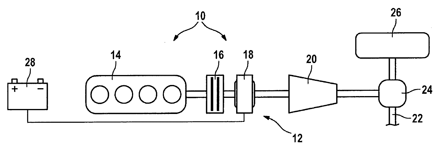
도1은 병렬 하이브리드 구동기의 구동 트레인의 구조가 도시된 도면이다.1 is a diagram showing the structure of a drive train of a parallel hybrid driver.
도2는 내연 기관, 특히 가솔린 직접 분사 오토 엔진의 선회각 및 목표 정지 영역이 도시된 도면이다.Figure 2 shows the turning angle and target stop area of an internal combustion engine, in particular a gasoline direct injection auto engine.
도3은 도1에 도시된 병렬 하이브리드 구동기의 부품들, 즉 적어도 하나의 전기 구동기의 내연 기관과 분리 클러치의 상호 작용을 제어하기 위한 시스템 구조가 도시된 도면이다.FIG. 3 shows a system structure for controlling the interaction of components of the parallel hybrid driver shown in FIG. 1, namely the internal combustion engine of the at least one electric driver and the separation clutch.
도4는 전기적 구동만에 의한 직접 시동에 의해, 연료 직접 분사 내연 기관을 시동하기 위한 알고리즘이 도시된 도면이다.4 is a diagram showing an algorithm for starting a fuel direct injection internal combustion engine by direct starting only by electric driving.
도5는 전기적 구동만에 의한, 그리고 내연 기관이 정지한 후 추후의 직접 시동 중의, 내연 기관의 조정이 도시된 도면이다.FIG. 5 shows the adjustment of the internal combustion engine only by electrical drive and during subsequent direct start after the internal combustion engine has stopped.
도6은 도5에 도시된 연료 직접 분사 내연 기관의 조정을 중단하며, 연료 직접 분사 내연 기관의 동역학적 직접 시동을 일으키는 시동 요구가 도시된 도면이다. FIG. 6 is a diagram illustrating a start up request to stop the adjustment of the fuel direct injection internal combustion engine shown in FIG. 5 and to cause a dynamic direct start of the fuel direct injection internal combustion engine.
도1에 따른 도면에서는 병렬 하이브리드로서 설계된 하이브리드 구동기가 제시된다.In the figure according to Figure 1 a hybrid driver designed as a parallel hybrid is presented.
도1에 도시된 하이브리드 구동기(10)는 병렬 하이브리드로서 설계되며, 내연 기관(14)이 수용된 구동 트레인(12)을 포함한다. 바람직하게 내연 기관(14)은 예컨대 가솔린 직접 분사부를 갖는 오토 엔진과 같은 연료 직접 분사 내연 기관이다. 또한 도1에 도시된 하이브리드 구동기(10)는 분리 클러치(16)와 적어도 하나의 전 기 구동기(18)를 포함한다. 분리 클러치(16)는 바람직하게 연료 직접 분사 내연 기관으로서 실시된 내연 기관(14)과 적어도 하나의 전기 구동기(18) 사이에 위치한다. 도1에 도시된 하이브리드 구동기(10)의 구동 트레인(12)은 구동축(22)의 축 변속기(24)에 작용하는 차량 변속기(20)를 포함한다. 구동축(22)에 수용된, 구동된 휠은 도면 부호 26으로 도시된다. 또한 도1에 도시된 하이브리드 구동기(10)는, 일반적으로 고전압 배터리로서 실시되며 적어도 하나의 전기 구동기(18)에 전류를 공급하는 트랙션 배터리(28)를 포함한다.The
구동 트레인(12)의 특수한 특징은 분리 클러치(16)가 개방되어 유지되는 전기적 구동만에 의한 작동을 위해서 사용될 수 있는 점이다. 트랙션 배터리(28)와 적어도 하나의 전기 구동기를 포함하는 전기 트랙션 분기의 출력이 차량의 추진을 위해서 더 이상 충분하지 않으면, 예컨대 직접 분사부를 갖는 오토 엔진일 수 있는 내연 기관(14)은 직접 시동에 의해 회전한다. 가솔린 직접 분사부를 갖는 오토 엔진과 같은 연료 직접 분사 내연 기관(14)의 사용은, 통상적인 스타터를 이용한 내연 기관(14)의 시동과 비교할 때, 소음 배출이 적게 발생하며, 그 외에도 필요한 스타터가 완전히 생략될 수 있는 장점을 제공하므로, 엔진 컴파트먼트 내에 추가의 구성 공간이 생기고, 구동된 휠에 대한 마찰 결합시 인장력을 무효화하는 시동이 실행될 수 있다. 또한 도1에 도시된 구동 트레인(12)은 하이브리드 구동기(10)에 의해, 짧은 시동 시간에 도달할 수 있는 특징을 갖는다.A special feature of the
도2의 도면에는, 연료 직접 분사부를 갖는 도1에 도시된 내연 기관의 실린더가 예시적으로 도시된다.In the figure of FIG. 2, the cylinder of the internal combustion engine shown in FIG. 1 with fuel direct injection is shown by way of example.
절반 단면도로 도시된 도2의 도면에서, 내연 기관(14)은 가솔린 직접 분사부를 갖는 오토 엔진과 같은 직접 분사 내연 기관이다. 바람직하게 가솔린 직접 분사부를 갖는 오토 엔진으로서 실시된 내연 기관(14)은 직접 시동에 의해서 시동될 수 있다. 연료는 그 피스톤(32)이 작동 행정 위치에 있는 실린더(30)의 연소실로 분사된다. 성공적인 시동을 위한 전제 조건은 상사점 이후 크랭크 샤프트(36)의 위치가 100°와 120°사이에 있는 것이다. 이러한 유형으로 구성된 내연 기관(14)의 직접 시동은 실린더(30) 내에 적은 량의 잔여 가스만 남아 있거나 잔여 가스가 남아 있지 않음으로써 바람직하다. 내연 기관(14)의 선행된 작동 주기 후 내연 기관은 정지하며, 내연 기관의 적어도 하나의 실린더는 도2에 도시된 선회각 영역(38) 내에 있다. 연료 직접 분사 내연 기관(14)의 실린더(30)의 피스톤(32)이 바람직하게 도달해야 하는 목표 정지 영역은 도2에서 도면 부호 40으로 도시된다. 그러나 내연 기관(14)이 정확히 목표 정지 영역(40) 내에 정지하는지가 확실하지 않기 때문에, 동역학적 직접 시동이 실행될 수 있다. 바람직하게 연료 직접 분사 내연 기관으로서 구현된 내연 기관(14)의 크랭크 샤프트(36)는 동역학적 직접 시동 내에서, 슬립 토크가 조절된 분리 클러치(16)에 의해서 제공된 외부 힘을 통해 이동한다. 내연 기관(14)에 할당된 엔진 제어부는 직접 시동에 적합한 위치를 인식하면 분사 및 점화될 수 있다.In the diagram of FIG. 2, shown in half section, the
도3에는 도1에 도시된 병렬 하이브리드 구동기의 부품인 내연 기관과, 전기 구동기와, 분리 클러치의 상호 작용을 제어하기 위한 시스템 구조가 도시된다.FIG. 3 shows a system structure for controlling the interaction of the internal combustion engine, the electric driver, and the separation clutch, which are parts of the parallel hybrid driver shown in FIG.
도3에 따른 도면에서, 시스템 구조는 차량의 운전자가 작동할 수 있는 가속 페달(50)을 포함한다. 가속 페달(50)에 의해서 운전자의 토크 요구가 변환된다. 운전자(MFahrer)의 토크 요구는 가속 페달(50)로부터 전체 시스템(하이브리드 제어)의 제어부(52)에 전달된다. 전체 시스템인 하이브리드 구동기의 제어 챔버(52)에는 내연 기관(14)을 위한 제어부(56)와, 적어도 하나의 전기 구동기(18)를 위한 제어부(58) 와, 도1의 도면에 따른 하이브리드 구동기(10)의 분리 클러치(16)를 조절하기 위한 제어부(60)가 부속된다.In the diagram according to FIG. 3, the system structure comprises an
제어부(52, 56, 58 및 60) 사이의 개별 인터페이스는 다음과 같다:The individual interfaces between the
내연 기관(14)의 제어부(56)로부터는, 내연 기관(14)의 회전수 정보(N_ENG)와, 내연 기관(14)의 직접 시동 준비를 나타내기 위한 상태 신호인 플래그(B_DST)와,내연 기관(14)의 드래그 토크에 대한 정보인 플래그(M_SCHLEPP)와, 경우에 따라 내연 기관(14)의 시동 과정의 종료를 나타내기 위한 정보인 플래그(B_ENG START)가 전체 시스템의 제어부(52)에 전달된다. 경우에 따라 상기 제어부는 내연 기관의 시동을 위한 정보인 플래그(B_START)를 내연 기관(14)의 제어부(56)에 다시 전송한다. 또한 운전자의 토크 요구(MFahrer)에 따라 내연 기관(14)을 통해 발생될 설정 토크에 대한 정보(M_ENGSOLL)가 내연 기관(14)의 제어부(56)에 전달된다. 마지막으로, 내연 기관(14)의 제어부(56)는 내연 기관(14)의 실제 회전수에 대한 회전수 정보(N_ENG)를 전체 시스템의 제어부(52)에 되돌려 보낸다.From the
전체 시스템의 제어부(52)는 적어도 하나의 전기 구동기(18)에 의해서 발생될 설정 토크(M_ELMSOLL)에 대한 정보를 적어도 하나의 전기 구동기(18)의 제어 부(58)에 출력하며, 제어부(58)로부터는 적어도 하나의 전기 구동기(18)의 최대로 변환 가능한 토크(M_ELMMAX)와, 적어도 하나의 전기 구동기(18)의 실제 회전수(N_ELM)에 대한 정보가 제공된다.The
하이브리드 구동기(10)의 분리 클러치(16)의 제어부(60)는 분리 클러치(16)의 실제 슬립 토크에 대한 정보(M_KUPPLIST)를 전체 시스템의 제어부(52)에 제공하며, 운전자 요구에 상응하게 분리 클러치(16)를 작동시키는, 사전 설정된 설정 슬립 토크(M_KUPPLSOLL)에 대한 정보를 상기 제어부(52)로부터 수신한다.The
도4에 따른 실시예에는, 도3에 도시된 시스템 구조 내에서의 상기 시스템 구조의 개별 부품들 사이의 정보 흐름이 도시된다.In the embodiment according to Fig. 4, the flow of information between the individual components of the system structure within the system structure shown in Fig. 3 is shown.
제1 단계(101)에서는 우선, 운전자의 토크 요구(MFahrer)가 적어도 하나의 전기 구동기(18)를 통해서만 충족될 수 있는지가 조회된다. 제1 단계(101) 내에서, 운전자의 토크 요구(MFahrer)는 적어도 하나의 전기 구동기(18)의 설정 토크(M_ELMSOLL)에서 공차(TOLERANZ)를 뺀 것보다 상기 토크 요구가 더 큰지에 대해 조회된다. 값(TOLERANZ)은, 내연 기관(14)의 시동에 필수적으로 연관되는 적어도 하나의 전기 구동기(18)의 회전수 감소를 보상하기 위해 내연 기관(14)의 시동시 사용되는 동역학적 예비분을 나타낸다. 제2 단계(102)에서는, 내연 기관(14)에 직접 시동 준비가 제공되는지가 조회되며, 즉 플래그(B_DST)가 세팅되는지 아닌지, 상기 플래그의 상태가 조회된다. 플래그(B_DST)가 세팅되면, 이는 내연 기관(14)이 직 접 시동 모드를 위해 위치 설정되고 직접 시동이 가능한 것을 의미한다. 그러나 내연 기관(14)을 시동시키기 위한 명령은 단계(108 또는 113)에서야 비로소 실행된다.In the
플래그(B_DST)가 세팅되지 않으면, 제3 단계(103)로 전환되며 분리 클러치(16)는 내연 기관(14)의 드래그 토크(M_SCHLEPP)로 조절된다. 이로써 내연 기관(14)은 회전한다. 적어도 하나의 전기 구동기(18)는 실제로 조정된 슬립 토크(M_KUPPLIST), 즉 분리 클러치의 실제 드래그 토크를 보상한다. 앞서 0으로 세팅된 타이머가 시작된다. 제3 단계(103)는 시구간(DELAY)이 경과될 때까지 실행된다. 제3 단계(103)에서, 설정 토크(M_KUPPLSOLL)는 내연 기관(14)의 드래그 토크(M_SCHLEPP)로 세팅되며, 적어도 하나의 전기 구동기(18)의 설정 토크(M_ELMSOLL)는 분리 클러치(16)의 M_KUPPLIST에 토크 요구(MFahrer)를 더한 값의 총합 토크로 세팅된다.If the flag B_DST is not set, it is switched to the
제4 방법 단계(104)에서는, 토크 요구(MFahrer)가 내연 기관(14)의 접속을 필요로 하는지가 다시 조사된다. 그렇다면, 제3 방법 단계(103)가 중단되어야 하며, 내연 기관(14)은 이 경우 분기되는 제8 단계(108)에서 실행되는 동역학적 시동에 의해서 시동되어야 한다.In a
제4 단계(104)의 결과가 부정적일 때, 연결되는 제5 단계(105)에서는, DELAY를 통해서 사전 설정된 시구간이 경과되는지가 조사된다. 그렇다면, 분리 클러 치(16)를 개방하는 제6 단계(106)로 분기되므로, 운전자의 토크 요구(MFahrer)는 적어도 하나의 전기 구동기(18)에 의해서만 변환된다. 이는 도면 부호 120으로 도시된, 전기적 구동만에 의한 작동을 특성화한다.When the result of the
제5 단계(105)의 결과가 부정적인 경우, 즉 시구간(DELAY)이 아직 경과되지 않을 때, 다시 제3 단계(103)로 분기되며 상기 단계가 새롭게 실행된다.If the result of the
제6 단계에 따라 실행되는, 전기적 구동만에 의한 작동(120)이 접속되면, 내연 기관(14)은 선회하며, 바람직하게는 도2에 도시된 시동 위치, 즉 목표 정지 영역(40)을 취한다. 또한 플래그(B_DST)의 질의를 통한 직접 시동 준비가 새롭게 조사된다.When the
토크 요구(MFahrer)가 전기 구동기(18)에 의해서만 충족될 수 있는지가 조사되는 제1 단계(101) 후, 제2 단계(102)와 동시에 제7 단계가 실행된다. 여기서 플래그(B_DST)의 상태가 조회된다.After the
적어도 하나의 전기 구동기(18)에 의해서 토크 요구(MFahrer)가 충족될 수 없고, 직접 시동 준비가 제공되지 않으면, 즉 플래그(B_DST)가 세팅되지 않으면, 제8 단계가 실행되며 동역학적 직접 시동이 시작된다. 이 경우, 플래그(B_START)는 값(TRUE)으로 세팅되고, 설정 토크(M_KUPPLSOLL)는 엔진 드래그 토크(M_SCHLEPP)로 세팅되며, 적어도 하나의 전기 구동기(18)의 설정 토크(M_ELMSOLL)는 분리 클러치(16)의 실제 토크(M_KUPPLIST)에 토크 요구(MFahrer)를 더한 총합으로부터 제시된 값 으로 세팅된다. 내연 기관(14)은 제어부(56)를 통해서 시동 명령을 받으며, 이와 동시에 내연 기관은 분리 클러치(16)의 시동을 통해서 회전한다. 이 경우 분리 클러치(16)는 앞서 언급한 바와 같이, 적어도 하나의 전기 구동기(18)에 의해서 보상되는 드래그 토크(M_SCHLEPP)로 조절된다.If the torque demand M Fahrer cannot be satisfied by at least one
제8 단계(108)에 연결되는 제9 단계(109)에서, 플래그(B_ENG START ENT)는, 상기 플래그가 세팅되는지 또는 변환되는지, 즉 내연 기관(14)이 시동되는지의 여부에 대해 조사된다.In a
내연 기관(14)이 시동되면, 제10 단계(110)에서 내연 기관(14)에 대한 시동 명령은 다시 철회되며, 즉 플래그(B_START)는 다시 값(FALSE)으로 세팅된다. 설정 슬립 토크(M_KUPPLSOLL)는 0으로 세팅되고, 적어도 하나의 전기 구동기(18)의 설정 토크(M_ELMSOLL)는 토크 요구(MFahrer)로 세팅되며, 내연 기관(14)의 설정 토크(M_ENGSOLL)는 값(MSTART)으로 세팅된다. 값(M_ENGSOLL)은 회전수에 따르는 설정 토크를 내연 기관(14)에 사전 설정하는 특성 곡선으로부터 나온다.When the
그 후, 제10 단계(110)에서는 적어도 하나의 전기 구동기(18)의 실제 회전수(NELM)에 의한 내연 기관의 동기화 중 상기 내연 기관(14)이 방해받지 않도록, 분리 클러치(16)가 개방된다.Then, in the
제10 단계(110)에 이어진 제11 단계(111)에서는, 내연 기관(14)의 회전수(N_ENG)가 적어도 하나의 전기 구동기(18)의 실제 회전수(N_ELM)와 동일한지가 조사된다. 그렇지 않다면, 다시 제10 단계(110)로 되돌아 분기된다. 그러하다면, 제12 단계(112)로 분기되며, 분리 클러치(16)의 설정 토크(M_KUPPLSOLL)는 최대로 전달될 수 있는 토크값(M_KUPPLMAX)으로 세팅된다. 제12 단계(112)의 실행 후, 하이브리드 구동기(130)가 제공되며, 즉 차량은 내연 기관(14)과 적어도 하나의 전기 구동기(18)에 의해서 동시에 구동된다.In the
제2 또는 제7 단계(102, 107)에 따라, 플래그(B_DST)가 값(TRUE)을 취하는 경우, 내연 기관(14)의 직접 시동 준비가 제공되며, 제8 단계(108)가 아니라, 제13 단계(113)로 분기되므로, 적어도 하나의 전기 구동기(18)에 의해서만 제시되지는 않는 운전자의 토크 요구(MFahrer)는 내연 기관(14)의 접속에 의해서 충족된다. 플래그(B_DST)가 세팅되기 때문에, 내연 기관(14)의 직접 시동 준비가 제공되고 내연 기관은 분리 클러치(16)의 폐쇄 과정을 통해서 이동하지 않고서도 시동될 수 있다. 이러한 바람직한 특성은, 가솔린 직접 분사부를 갖는 오토 엔진과 같은, 연료 직접 분사 내연 기관(14)과 연관되어 바람직하게 사용된다.According to the second or
제13 단계(113)의 실행 후, 내연 기관(14)이 시동되는지, 즉 플래그(B_ENG START END)의 상태가 값(TRUE 또는 FALSE)인지가 조회된 다음, 앞서 이미 설명한 제10 단계(110)로 분기된다.After execution of the
도5에 따른 도면에는, 전기 주행 모드 중 내연 기관의 조정과, 이로부터 실행된, 정지한 내연 기관의 추후의 직접 시동이 제시된다.In the diagram according to FIG. 5, the adjustment of the internal combustion engine during the electric running mode and the subsequent direct start of the stationary internal combustion engine executed therefrom are presented.
내연 기관(14)은 도5의 도면에 따라, 전기적 구동만에 의한 작동(120) 중 조정된다. 도5에서 DELAY로 표현된 2개의 시구간 중, 전체 시스템의 제어부(52)는 내연 기관에 의한 직접 시동 준비가 나타날 때까지, 즉 플래그(B_DST)가 값(TRUE)을 취할 때까지, 2회의 시동 시도를 실행한다. 이는 도5에서 플래그(B_DST)의 상태를 재현하는 신호 곡선(140)으로부터 제시된다. 적어도 하나의 전기 구동기에 의한 토크 요구(MFahrer)가 더 이상 충족될 수 없는 시점, 즉 최대로 조정될 적어도 하나의 전기 구동기의 토크(M_ELMMAX)에서 공차(TOLERANZ)를 뺀 값보다 토크 요구(MFahrer)가 큰 시점일 때, 내연 기관(14)은 시동되며, 즉 플래그(B_START)(도5의 신호 곡선(141) 참조)는 값(TRUE)으로 세팅된다. 도5에는 내연 기관(14)의 회전수(N_ENG)의 심한 회전수 증가에 의한 성공적인 시동이 도시된다. 내연 기관의 회전수(M_ENG)와 전기 구동기의 회전수가 서로 동기화되면, 분리 클러치(16)는 폐쇄된다. 분리 클러치(16)의 폐쇄를 위해, 최대 설정 토크가 사전 설정되므로, 분리 클러치(16)는 완전히 폐쇄된다.The
도4와 연관해서 설명된 신호 흐름도에 따라, 방법 단계는 이하의 순서: 102, 103, 104, 106, 102, 103, 104, 106, 101, 113, 114, 110, 111 및 112로 실행된다.In accordance with the signal flow diagram described in connection with FIG. 4, the method steps are executed in the following order: 102, 103, 104, 106, 102, 103, 104, 106, 101, 113, 114, 110, 111, and 112.
도6에 따른 도면에는, 도5에 도시된 조정이 중단되고 동역학적 직접 시동이 요구되는 내연 기관에 대한 시동 요구 조건이 제시된다.In the diagram according to FIG. 6, the starting requirements for the internal combustion engine, in which the adjustment shown in FIG. 5 is interrupted and dynamic direct start is required, are presented.
도6에 도시된 경우, 조정은 구동기에 대해서 더 증가된 토크 요구(MFahrer)에 의해서 중단되며, 이는 수직으로 도시된 점선으로 도시된다. 이 경우, 토크 요구(MFahrer)는 적어도 하나의 전기 구동기(18)에 의해서 조정 가능한 최대 토 크(M_ELMMAX)에서 공차(TOLERANZ)를 뺀 값을 초과한다. 이 경우 도4의 도면에 따른 제8 방법 단계(108)는 동역학적 직접 시동의 실행을 위해 실행된다. 플래그(B_START)의 상태의 곡선(141)에 따라, 플래그는 값(TRUE)으로 세팅되며, 내연 기관의 직접 시동 준비를 나타내기 위한 플래그(B_DST)는 TRUE로 세팅되고, 내연 기관은 분리 클러치(16)의 폐쇄에 의해서 회전한다. 이러한 과정의 경우, 분리 클러치(16)는 내연 기관(14)의 드래그 토크(M_SCHLEPP)로 조절된다. 분리 클러치(16)와 내연 기관(14)을 통해서 전달된 드래그 토크(M_SCHLEPP)는, 그 회전수가 감소하는 적어도 하나의 전기 구동기(18)에 의해서 보상되어야 한다. 도6의 도면에 따르면, 도4의 흐름도에 따라 후속 단계: 102, 103, 104, 102, 103, 104, 108, 109, 108, 109, 110, 111 및 112가 실행된다.In the case shown in Fig. 6, the adjustment is interrupted by an increased torque demand M Fahrer for the driver, which is shown by the dashed line shown vertically. In this case, the torque demand M Fahrer exceeds the maximum torque M_ELM MAX which is adjustable by the at least one
Claims (11)
Applications Claiming Priority (2)
| Application Number | Priority Date | Filing Date | Title |
|---|---|---|---|
| DE102006008640A DE102006008640A1 (en) | 2006-02-24 | 2006-02-24 | Hybrid drive method with direct starting supporting decoupler e.g. for internal combustion engines, involves having hybrid drive of vehicle with internal combustion engine and electric drive which has assigned traction battery |
| DE102006008640.6 | 2006-02-24 |
Publications (2)
| Publication Number | Publication Date |
|---|---|
| KR20080098380A true KR20080098380A (en) | 2008-11-07 |
| KR101092679B1 KR101092679B1 (en) | 2011-12-09 |
Family
ID=38000817
Family Applications (1)
| Application Number | Title | Priority Date | Filing Date |
|---|---|---|---|
| KR1020087020638A Expired - Fee Related KR101092679B1 (en) | 2006-02-24 | 2007-01-30 | Hybrid drive having a separating clutch which assists a direct start and method for operating thereof |
Country Status (7)
| Country | Link |
|---|---|
| US (1) | US8480536B2 (en) |
| EP (1) | EP1991454B1 (en) |
| JP (1) | JP4638946B2 (en) |
| KR (1) | KR101092679B1 (en) |
| CN (1) | CN101389519B (en) |
| DE (1) | DE102006008640A1 (en) |
| WO (1) | WO2007099003A1 (en) |
Cited By (1)
| Publication number | Priority date | Publication date | Assignee | Title |
|---|---|---|---|---|
| WO2014104676A1 (en) * | 2012-12-24 | 2014-07-03 | 두산인프라코어 주식회사 | Power supply device for hybrid construction machinery, and method therefor |
Families Citing this family (37)
| Publication number | Priority date | Publication date | Assignee | Title |
|---|---|---|---|---|
| KR101517260B1 (en) * | 2007-12-20 | 2015-05-04 | 폭스바겐 악티엔 게젤샤프트 | Method and device for operating a hybrid vehicle |
| DE102007062796A1 (en) * | 2007-12-27 | 2009-07-02 | Robert Bosch Gmbh | Method for operating a hybrid drive device |
| DE102008002666B4 (en) | 2008-06-26 | 2017-08-31 | Robert Bosch Gmbh | Method and device for starting an internal combustion engine of a hybrid drive train |
| DE102008042685A1 (en) * | 2008-10-08 | 2010-04-15 | Robert Bosch Gmbh | Method for adapting a separating clutch in a drive train arrangement of a vehicle and drive train arrangement |
| DE102008043945A1 (en) * | 2008-11-20 | 2010-05-27 | Robert Bosch Gmbh | Method and device for operating a hybrid drive for a vehicle |
| DE102008044016B4 (en) * | 2008-11-24 | 2025-07-31 | Robert Bosch Gmbh | Method for detecting an emerging torque for a hybrid drive |
| US20100276218A1 (en) * | 2009-04-29 | 2010-11-04 | Ford Global Technologies, Llc | Hybrid electric vehicle powertrain having high vehicle speed engine starts |
| DE102009002991A1 (en) * | 2009-05-11 | 2010-11-18 | Robert Bosch Gmbh | Control unit, in particular for a hybrid vehicle with an electric drive and an internal combustion engine, and method for operating a hybrid vehicle |
| DE102009027001A1 (en) | 2009-06-17 | 2010-12-23 | Robert Bosch Gmbh | Method and device for determining the beginning of a starting phase of an internal combustion engine in a hybrid vehicle |
| DE102009027642A1 (en) * | 2009-07-13 | 2011-01-20 | Robert Bosch Gmbh | Method for operating a hybrid vehicle and corresponding drive device |
| DE102010008680A1 (en) * | 2010-02-19 | 2011-08-25 | Dr. Ing. h.c. F. Porsche Aktiengesellschaft, 70435 | Method for controlling a drive train in a motor vehicle, drive train control for a motor vehicle, control unit for a conveyor for providing oil pressure in a motor vehicle, method for fault detection in a hydraulic system for a motor vehicle and hydraulic system for a motor vehicle |
| JP5617301B2 (en) * | 2010-03-25 | 2014-11-05 | マツダ株式会社 | Vehicle drive control device |
| JP5545018B2 (en) * | 2010-05-12 | 2014-07-09 | マツダ株式会社 | Vehicle drive control device |
| JP5545017B2 (en) * | 2010-05-12 | 2014-07-09 | マツダ株式会社 | Vehicle drive control device |
| US10479184B2 (en) * | 2010-09-30 | 2019-11-19 | Evaos, Inc. | Auxiliary electric drive system and vehicle using same |
| WO2013014797A1 (en) | 2011-07-28 | 2013-01-31 | トヨタ自動車株式会社 | Engine stop control device for hybrid vehicle |
| WO2013030986A1 (en) * | 2011-08-31 | 2013-03-07 | トヨタ自動車株式会社 | Engine stop control device for hybrid vehicle |
| WO2013030987A1 (en) * | 2011-08-31 | 2013-03-07 | トヨタ自動車株式会社 | Engine startup control device for hybrid vehicle |
| JP5804068B2 (en) * | 2011-08-31 | 2015-11-04 | トヨタ自動車株式会社 | Engine start control device for hybrid vehicle |
| JP5729477B2 (en) * | 2011-09-06 | 2015-06-03 | トヨタ自動車株式会社 | Control device for hybrid vehicle |
| DE112011105712T5 (en) * | 2011-10-06 | 2014-08-07 | Toyota Jidosha Kabushiki Kaisha | Maschinenstartsytem |
| EP2769893A4 (en) * | 2011-10-20 | 2016-08-24 | Toyota Motor Co Ltd | ENGINE START CONTROL DEVICE FOR HYBRID VEHICLE |
| JP5761365B2 (en) * | 2011-10-27 | 2015-08-12 | トヨタ自動車株式会社 | Control device for hybrid vehicle |
| JP5927626B2 (en) * | 2011-10-28 | 2016-06-01 | ダイハツ工業株式会社 | Clutch timing control device |
| DE102012204849A1 (en) | 2012-03-27 | 2013-10-02 | Robert Bosch Gmbh | Method and control device for controlling a hybrid drive of a hybrid electric motor vehicle |
| DE102012206157A1 (en) * | 2012-04-16 | 2013-10-17 | Zf Friedrichshafen Ag | Control device of a hybrid vehicle and method for operating the same |
| CN104684778B (en) * | 2012-09-18 | 2017-05-17 | 丰田自动车株式会社 | Control device for vehicle drive device |
| JP5724975B2 (en) | 2012-09-18 | 2015-05-27 | トヨタ自動車株式会社 | Control device for vehicle |
| DE112013006898T5 (en) * | 2013-04-01 | 2015-12-31 | Toyota Jidosha Kabushiki Kaisha | Stop control device for an internal combustion engine |
| US10006430B2 (en) | 2013-04-16 | 2018-06-26 | Toyota Jidosha Kabushiki Kaisha | Vehicle control device |
| JP2015017543A (en) * | 2013-07-10 | 2015-01-29 | トヨタ自動車株式会社 | Vehicle control device |
| DE102013225150A1 (en) * | 2013-12-06 | 2015-06-11 | Volkswagen Aktiengesellschaft | Method for starting an internal combustion engine of a motor vehicle and motor vehicle |
| US9481256B2 (en) * | 2014-01-30 | 2016-11-01 | Amp Electric Vehicles Inc. | Onboard generator drive system for electric vehicles |
| CN104842997A (en) * | 2014-07-04 | 2015-08-19 | 北汽福田汽车股份有限公司 | Engine starting method of hybrid power vehicle power system |
| DE102017200982B4 (en) | 2017-01-23 | 2021-09-16 | Audi Ag | Method for operating a drive device for a motor vehicle and a corresponding drive device |
| US10543739B1 (en) | 2018-07-25 | 2020-01-28 | Fca Us Llc | Mode transition control techniques for an electrically all-wheel drive hybrid vehicle |
| DE102021107414A1 (en) | 2021-03-24 | 2022-09-29 | Bayerische Motoren Werke Aktiengesellschaft | Drive device and method for controlling drive device |
Family Cites Families (34)
| Publication number | Priority date | Publication date | Assignee | Title |
|---|---|---|---|---|
| JP3870505B2 (en) | 1997-08-29 | 2007-01-17 | アイシン・エィ・ダブリュ株式会社 | Hybrid drive device for vehicle |
| DE10006861A1 (en) | 1999-05-10 | 2000-11-30 | Bosch Gmbh Robert | Drive train arrangement for motor vehicle has dual coupling plate associated with both couplings to enable selective setting of relevant coupling status |
| DE10025853A1 (en) | 1999-06-02 | 2001-04-19 | Luk Lamellen & Kupplungsbau | Drive train for automotive vehicle includes coupling members having their coupling states established independently from coupling state of other coupling members |
| JP2001055941A (en) * | 1999-08-16 | 2001-02-27 | Honda Motor Co Ltd | Engine automatic start / stop control device |
| IT1319883B1 (en) * | 2000-02-04 | 2003-11-12 | Fiat Ricerche | PROCEDURE AND CONTROL SYSTEM FOR THE PROPULSION OF A VEHICLE |
| US7407026B2 (en) * | 2000-10-11 | 2008-08-05 | Ford Global Technologies, Llc | Control system for a hybrid electric vehicle to anticipate the need for a mode change |
| JP3454245B2 (en) * | 2000-10-26 | 2003-10-06 | トヨタ自動車株式会社 | Vehicle start control device |
| US6543565B1 (en) * | 2000-11-10 | 2003-04-08 | Ford Motor Company | Method and system for collecting regenerative braking energy in a parallel hybrid electric vehicle |
| JP3593983B2 (en) * | 2001-01-16 | 2004-11-24 | 日産自動車株式会社 | Vehicle driving force control device |
| WO2003049969A2 (en) * | 2001-12-13 | 2003-06-19 | Siemens Aktiengesellschaft | Drivetrain on a motor vehicle and method for controlling a drivetrain |
| EP1497151B1 (en) * | 2002-04-10 | 2009-04-08 | LuK Lamellen und Kupplungsbau Beteiligungs KG | Method for operating a motor vehicle |
| JP3809824B2 (en) * | 2002-09-10 | 2006-08-16 | トヨタ自動車株式会社 | Hybrid car |
| DE10303822A1 (en) | 2003-01-31 | 2004-08-12 | Volkswagen Ag | Drive arrangement for motor vehicle enables direct start to be carried out with combustion engine so that engine can be started without interrupting traction force when driving vehicle with starter |
| JP3815441B2 (en) * | 2003-02-04 | 2006-08-30 | トヨタ自動車株式会社 | Internal combustion engine stop / start control device |
| JP3941705B2 (en) | 2003-02-13 | 2007-07-04 | トヨタ自動車株式会社 | Internal combustion engine stop / start control device |
| JP2004346811A (en) * | 2003-05-21 | 2004-12-09 | Toyota Motor Corp | Hybrid vehicle and method of starting internal combustion engine mounted on hybrid vehicle |
| US7216729B2 (en) * | 2003-09-19 | 2007-05-15 | Ford Global Technologies, Llc | Method and system of requesting engine on/off state in a hybrid electric vehicle |
| DE10356384A1 (en) | 2003-12-03 | 2005-06-30 | E. Zoller GmbH & Co. KG Einstell- und Messgeräte | Lighting system of light emitting diodes is used to illuminate tip of cutting tool in measuring system |
| JP3912368B2 (en) * | 2003-12-05 | 2007-05-09 | 日産自動車株式会社 | Engine start-up method for vehicles with hybrid transmission |
| US7082899B2 (en) | 2004-03-26 | 2006-08-01 | Bose Corporation | Controlled starting and braking of an internal combustion engine |
| JP4412025B2 (en) | 2004-03-29 | 2010-02-10 | マツダ株式会社 | Engine starter |
| US7013213B2 (en) * | 2004-05-12 | 2006-03-14 | Ford Global Technologies, Llc | Method for controlling starting of an engine in a hybrid electric vehicle powertrain |
| DE102004023673B4 (en) | 2004-05-13 | 2017-12-14 | Volkswagen Ag | Method for controlling the drive train of a hybrid vehicle |
| US7214156B2 (en) * | 2004-06-18 | 2007-05-08 | Eaton Corporation | Start and operation sequences for hybrid motor vehicles |
| US7350602B2 (en) * | 2004-07-19 | 2008-04-01 | Ford Global Technologies, Llc | System and method for engine start detection for hybrid vehicles |
| US7085631B2 (en) * | 2004-07-29 | 2006-08-01 | Ford Global Technologies, Llc | Vehicle and method for operating an engine in a vehicle |
| US7370715B2 (en) * | 2004-12-28 | 2008-05-13 | Ford Global Technologies, Llc | Vehicle and method for controlling engine start in a vehicle |
| US7469667B2 (en) * | 2005-07-07 | 2008-12-30 | Ford Global Technologies, Llc | Method for controlling a variable event valvetrain |
| JP2007040279A (en) * | 2005-08-05 | 2007-02-15 | Toyota Motor Corp | Control device for internal combustion engine |
| JP4341610B2 (en) * | 2005-11-09 | 2009-10-07 | 日産自動車株式会社 | Engine restart control device for hybrid vehicle |
| US7546821B2 (en) * | 2006-03-02 | 2009-06-16 | Ford Global Technologies, Llc | Hydraulic actuation system for improved engine start |
| JP4749988B2 (en) * | 2006-10-23 | 2011-08-17 | 日立オートモティブシステムズ株式会社 | Start control device for internal combustion engine |
| US7552705B2 (en) * | 2007-03-07 | 2009-06-30 | The Gates Corporation | Vehicle stop/start system with regenerative braking |
| JP4535135B2 (en) * | 2008-01-17 | 2010-09-01 | トヨタ自動車株式会社 | Start control device |
-
2006
- 2006-02-24 DE DE102006008640A patent/DE102006008640A1/en not_active Withdrawn
-
2007
- 2007-01-30 JP JP2008555728A patent/JP4638946B2/en not_active Expired - Fee Related
- 2007-01-30 WO PCT/EP2007/050867 patent/WO2007099003A1/en not_active Ceased
- 2007-01-30 KR KR1020087020638A patent/KR101092679B1/en not_active Expired - Fee Related
- 2007-01-30 CN CN2007800065983A patent/CN101389519B/en active Active
- 2007-01-30 US US12/162,819 patent/US8480536B2/en not_active Expired - Fee Related
- 2007-01-30 EP EP07704220.8A patent/EP1991454B1/en not_active Not-in-force
Cited By (2)
| Publication number | Priority date | Publication date | Assignee | Title |
|---|---|---|---|---|
| WO2014104676A1 (en) * | 2012-12-24 | 2014-07-03 | 두산인프라코어 주식회사 | Power supply device for hybrid construction machinery, and method therefor |
| US9783066B2 (en) | 2012-12-24 | 2017-10-10 | Doosan Infracore Co., Ltd. | Power supply device for hybrid construction machinery, and method therefor |
Also Published As
| Publication number | Publication date |
|---|---|
| CN101389519B (en) | 2012-12-05 |
| CN101389519A (en) | 2009-03-18 |
| US20090105038A1 (en) | 2009-04-23 |
| US8480536B2 (en) | 2013-07-09 |
| KR101092679B1 (en) | 2011-12-09 |
| DE102006008640A1 (en) | 2007-08-30 |
| EP1991454A1 (en) | 2008-11-19 |
| JP4638946B2 (en) | 2011-02-23 |
| EP1991454B1 (en) | 2013-10-09 |
| WO2007099003A1 (en) | 2007-09-07 |
| JP2009527411A (en) | 2009-07-30 |
Similar Documents
| Publication | Publication Date | Title |
|---|---|---|
| KR101092679B1 (en) | Hybrid drive having a separating clutch which assists a direct start and method for operating thereof | |
| US6524223B2 (en) | Drive train for a motor vehicle | |
| JP3775012B2 (en) | Hybrid drive device for vehicle | |
| KR101632453B1 (en) | Method and device for starting an internal combustion engine of a hybrid drive train | |
| US7610891B2 (en) | Method for controlling the start-up phase of a motor vehicle | |
| KR101722869B1 (en) | Hybrid electric vehicle control system and method | |
| US11136011B2 (en) | Method and system for vehicle control | |
| US8360929B2 (en) | Method and control device for operating a hybrid drive | |
| US6418899B1 (en) | Electric drive arrangement for internal combustion engines in motor vehicles | |
| CN105365807A (en) | Methods and systems for starting an engine | |
| US20090063029A1 (en) | Method for starting an internal combustion engine | |
| CN106460687A (en) | Implementing skip fire with start/stop feature | |
| US10189460B2 (en) | Methods and system for operating a vehicle transmission | |
| RU2692862C2 (en) | Regulation of charging from generator taking into account of additional fuel consumption | |
| JP2003515051A (en) | Impulse start method and apparatus for an internal combustion engine | |
| CA2626605C (en) | Method and system for shutting down an engine in a hybrid vehicle | |
| CN104228825A (en) | method for operating a vehicle | |
| CN110466496A (en) | System and method for a hybrid vehicle with a manual shift transmission | |
| CN114165340A (en) | Belt-driven starter-generator assisted engine shutdown | |
| CN104010857B (en) | The control device of hybrid vehicle and the method run for it | |
| US11519498B2 (en) | Methods and system for engine control during gear shifting in a hybrid electric vehicle | |
| US20130298875A1 (en) | Method for operating a motor vehicle | |
| JP5617301B2 (en) | Vehicle drive control device | |
| US20070277773A1 (en) | Method And Device For Stopping And Starting The Engine Of Hybrid Vehicles | |
| EP2301817B1 (en) | Electric power generation control system for internal combustion engine |
Legal Events
| Date | Code | Title | Description |
|---|---|---|---|
| PA0105 | International application |
St.27 status event code: A-0-1-A10-A15-nap-PA0105 |
|
| PG1501 | Laying open of application |
St.27 status event code: A-1-1-Q10-Q12-nap-PG1501 |
|
| A201 | Request for examination | ||
| PA0201 | Request for examination |
St.27 status event code: A-1-2-D10-D11-exm-PA0201 |
|
| P11-X000 | Amendment of application requested |
St.27 status event code: A-2-2-P10-P11-nap-X000 |
|
| P13-X000 | Application amended |
St.27 status event code: A-2-2-P10-P13-nap-X000 |
|
| E902 | Notification of reason for refusal | ||
| PE0902 | Notice of grounds for rejection |
St.27 status event code: A-1-2-D10-D21-exm-PE0902 |
|
| T11-X000 | Administrative time limit extension requested |
St.27 status event code: U-3-3-T10-T11-oth-X000 |
|
| P11-X000 | Amendment of application requested |
St.27 status event code: A-2-2-P10-P11-nap-X000 |
|
| P13-X000 | Application amended |
St.27 status event code: A-2-2-P10-P13-nap-X000 |
|
| E701 | Decision to grant or registration of patent right | ||
| PE0701 | Decision of registration |
St.27 status event code: A-1-2-D10-D22-exm-PE0701 |
|
| GRNT | Written decision to grant | ||
| PR0701 | Registration of establishment |
St.27 status event code: A-2-4-F10-F11-exm-PR0701 |
|
| PR1002 | Payment of registration fee |
St.27 status event code: A-2-2-U10-U12-oth-PR1002 Fee payment year number: 1 |
|
| PG1601 | Publication of registration |
St.27 status event code: A-4-4-Q10-Q13-nap-PG1601 |
|
| FPAY | Annual fee payment |
Payment date: 20141204 Year of fee payment: 4 |
|
| PR1001 | Payment of annual fee |
St.27 status event code: A-4-4-U10-U11-oth-PR1001 Fee payment year number: 4 |
|
| PR1001 | Payment of annual fee |
St.27 status event code: A-4-4-U10-U11-oth-PR1001 Fee payment year number: 5 |
|
| FPAY | Annual fee payment |
Payment date: 20161201 Year of fee payment: 6 |
|
| PR1001 | Payment of annual fee |
St.27 status event code: A-4-4-U10-U11-oth-PR1001 Fee payment year number: 6 |
|
| FPAY | Annual fee payment |
Payment date: 20171129 Year of fee payment: 7 |
|
| PR1001 | Payment of annual fee |
St.27 status event code: A-4-4-U10-U11-oth-PR1001 Fee payment year number: 7 |
|
| FPAY | Annual fee payment |
Payment date: 20181127 Year of fee payment: 8 |
|
| PR1001 | Payment of annual fee |
St.27 status event code: A-4-4-U10-U11-oth-PR1001 Fee payment year number: 8 |
|
| R17-X000 | Change to representative recorded |
St.27 status event code: A-5-5-R10-R17-oth-X000 |
|
| R18-X000 | Changes to party contact information recorded |
St.27 status event code: A-5-5-R10-R18-oth-X000 |
|
| R18-X000 | Changes to party contact information recorded |
St.27 status event code: A-5-5-R10-R18-oth-X000 |
|
| FPAY | Annual fee payment |
Payment date: 20191126 Year of fee payment: 9 |
|
| PR1001 | Payment of annual fee |
St.27 status event code: A-4-4-U10-U11-oth-PR1001 Fee payment year number: 9 |
|
| PR1001 | Payment of annual fee |
St.27 status event code: A-4-4-U10-U11-oth-PR1001 Fee payment year number: 10 |
|
| PR1001 | Payment of annual fee |
St.27 status event code: A-4-4-U10-U11-oth-PR1001 Fee payment year number: 11 |
|
| PR1001 | Payment of annual fee |
St.27 status event code: A-4-4-U10-U11-oth-PR1001 Fee payment year number: 12 |
|
| PR1001 | Payment of annual fee |
St.27 status event code: A-4-4-U10-U11-oth-PR1001 Fee payment year number: 13 |
|
| PC1903 | Unpaid annual fee |
St.27 status event code: A-4-4-U10-U13-oth-PC1903 Not in force date: 20241206 Payment event data comment text: Termination Category : DEFAULT_OF_REGISTRATION_FEE |
|
| H13 | Ip right lapsed |
Free format text: ST27 STATUS EVENT CODE: N-4-6-H10-H13-OTH-PC1903 (AS PROVIDED BY THE NATIONAL OFFICE); TERMINATION CATEGORY : DEFAULT_OF_REGISTRATION_FEE Effective date: 20241206 |
|
| PC1903 | Unpaid annual fee |
St.27 status event code: N-4-6-H10-H13-oth-PC1903 Ip right cessation event data comment text: Termination Category : DEFAULT_OF_REGISTRATION_FEE Not in force date: 20241206 |