KR20080098351A - Disc gripping device - Google Patents
Disc gripping device Download PDFInfo
- Publication number
- KR20080098351A KR20080098351A KR1020080104627A KR20080104627A KR20080098351A KR 20080098351 A KR20080098351 A KR 20080098351A KR 1020080104627 A KR1020080104627 A KR 1020080104627A KR 20080104627 A KR20080104627 A KR 20080104627A KR 20080098351 A KR20080098351 A KR 20080098351A
- Authority
- KR
- South Korea
- Prior art keywords
- disk
- disc
- gripping
- arm
- center hole
- Prior art date
- Legal status (The legal status is an assumption and is not a legal conclusion. Google has not performed a legal analysis and makes no representation as to the accuracy of the status listed.)
- Granted
Links
Images


Classifications
-
- G—PHYSICS
- G11—INFORMATION STORAGE
- G11B—INFORMATION STORAGE BASED ON RELATIVE MOVEMENT BETWEEN RECORD CARRIER AND TRANSDUCER
- G11B23/00—Record carriers not specific to the method of recording or reproducing; Accessories, e.g. containers, specially adapted for co-operation with the recording or reproducing apparatus ; Intermediate mediums; Apparatus or processes specially adapted for their manufacture
-
- G—PHYSICS
- G11—INFORMATION STORAGE
- G11B—INFORMATION STORAGE BASED ON RELATIVE MOVEMENT BETWEEN RECORD CARRIER AND TRANSDUCER
- G11B7/00—Recording or reproducing by optical means, e.g. recording using a thermal beam of optical radiation by modifying optical properties or the physical structure, reproducing using an optical beam at lower power by sensing optical properties; Record carriers therefor
- G11B7/24—Record carriers characterised by shape, structure or physical properties, or by the selection of the material
- G11B7/26—Apparatus or processes specially adapted for the manufacture of record carriers
-
- B—PERFORMING OPERATIONS; TRANSPORTING
- B25—HAND TOOLS; PORTABLE POWER-DRIVEN TOOLS; MANIPULATORS
- B25J—MANIPULATORS; CHAMBERS PROVIDED WITH MANIPULATION DEVICES
- B25J15/00—Gripping heads and other end effectors
- B25J15/08—Gripping heads and other end effectors having finger members
- B25J15/10—Gripping heads and other end effectors having finger members with three or more finger members
-
- G—PHYSICS
- G11—INFORMATION STORAGE
- G11B—INFORMATION STORAGE BASED ON RELATIVE MOVEMENT BETWEEN RECORD CARRIER AND TRANSDUCER
- G11B17/00—Guiding record carriers not specifically of filamentary or web form, or of supports therefor
- G11B17/02—Details
- G11B17/022—Positioning or locking of single discs
- G11B17/028—Positioning or locking of single discs of discs rotating during transducing operation
-
- G—PHYSICS
- G11—INFORMATION STORAGE
- G11B—INFORMATION STORAGE BASED ON RELATIVE MOVEMENT BETWEEN RECORD CARRIER AND TRANSDUCER
- G11B17/00—Guiding record carriers not specifically of filamentary or web form, or of supports therefor
- G11B17/02—Details
- G11B17/04—Feeding or guiding single record carrier to or from transducer unit
-
- G—PHYSICS
- G11—INFORMATION STORAGE
- G11B—INFORMATION STORAGE BASED ON RELATIVE MOVEMENT BETWEEN RECORD CARRIER AND TRANSDUCER
- G11B17/00—Guiding record carriers not specifically of filamentary or web form, or of supports therefor
- G11B17/08—Guiding record carriers not specifically of filamentary or web form, or of supports therefor from consecutive-access magazine of disc records
-
- G—PHYSICS
- G11—INFORMATION STORAGE
- G11B—INFORMATION STORAGE BASED ON RELATIVE MOVEMENT BETWEEN RECORD CARRIER AND TRANSDUCER
- G11B17/00—Guiding record carriers not specifically of filamentary or web form, or of supports therefor
- G11B17/22—Guiding record carriers not specifically of filamentary or web form, or of supports therefor from random access magazine of disc records
-
- G—PHYSICS
- G11—INFORMATION STORAGE
- G11B—INFORMATION STORAGE BASED ON RELATIVE MOVEMENT BETWEEN RECORD CARRIER AND TRANSDUCER
- G11B23/00—Record carriers not specific to the method of recording or reproducing; Accessories, e.g. containers, specially adapted for co-operation with the recording or reproducing apparatus ; Intermediate mediums; Apparatus or processes specially adapted for their manufacture
- G11B23/02—Containers; Storing means both adapted to cooperate with the recording or reproducing means
- G11B23/03—Containers for flat record carriers
-
- G—PHYSICS
- G11—INFORMATION STORAGE
- G11B—INFORMATION STORAGE BASED ON RELATIVE MOVEMENT BETWEEN RECORD CARRIER AND TRANSDUCER
- G11B23/00—Record carriers not specific to the method of recording or reproducing; Accessories, e.g. containers, specially adapted for co-operation with the recording or reproducing apparatus ; Intermediate mediums; Apparatus or processes specially adapted for their manufacture
- G11B23/38—Visual features other than those contained in record tracks or represented by sprocket holes the visual signals being auxiliary signals
- G11B23/40—Identifying or analogous means applied to or incorporated in the record carrier and not intended for visual display simultaneously with the playing-back of the record carrier, e.g. label, leader, photograph
-
- Y—GENERAL TAGGING OF NEW TECHNOLOGICAL DEVELOPMENTS; GENERAL TAGGING OF CROSS-SECTIONAL TECHNOLOGIES SPANNING OVER SEVERAL SECTIONS OF THE IPC; TECHNICAL SUBJECTS COVERED BY FORMER USPC CROSS-REFERENCE ART COLLECTIONS [XRACs] AND DIGESTS
- Y10—TECHNICAL SUBJECTS COVERED BY FORMER USPC
- Y10S—TECHNICAL SUBJECTS COVERED BY FORMER USPC CROSS-REFERENCE ART COLLECTIONS [XRACs] AND DIGESTS
- Y10S294/00—Handling: hand and hoist-line implements
- Y10S294/902—Gripping element
Landscapes
- Engineering & Computer Science (AREA)
- Robotics (AREA)
- Mechanical Engineering (AREA)
- Manufacturing & Machinery (AREA)
- Holding Or Fastening Of Disk On Rotational Shaft (AREA)
- Automatic Disk Changers (AREA)
- Manufacturing Optical Record Carriers (AREA)
- Manufacturing Of Magnetic Record Carriers (AREA)
- Manipulator (AREA)
Abstract
3개 이상의 그립핑 부재를 디스크의 중심 구멍에 삽입하고, 하나 이상의 그립핑 부재를 반경 방향으로 확장하여 상기 중심 구멍의 내주면을 푸싱함으로써 디스크를 그립핑하는 디스크 그립핑 장치가 구성된다. 3개 이상의 그립핑 부재는 상기 중심 구멍의 내주면과 접촉하는 디스크 접촉면을 구비하고 디스크 접촉면의 길이가 상기 중심 구멍의 내주면 두께보다 큰 제 1 그립핑 부재; 상기 중심 구멍의 내주면과 접촉하는 디스크 접촉면을 구비하고, 디스크 접촉면의 길이가 상기 중심 구멍의 내주면의 두께 이하인 제 2 그립핑 부재; 및 상기 중심 구멍의 내주면과 접촉하는 디스크 접촉면을 구비한 제 3 그립핑 부재를 포함한다. A disk gripping device is constructed that inserts three or more gripping members into a central hole of a disc and grips the disc by pushing one or more gripping members radially to push the inner circumferential surface of the central hole. At least three gripping members having a disk contact surface in contact with an inner circumferential surface of the center hole and having a length of the disk contact surface greater than a thickness of the inner circumferential surface of the center hole; A second gripping member having a disk contact surface in contact with the inner circumferential surface of the center hole, wherein the length of the disk contact surface is equal to or less than the thickness of the inner circumferential surface of the center hole; And a third gripping member having a disk contact surface in contact with the inner circumferential surface of the center hole.
Description
본 발명은 디스크 더빙 장치 및 CD/DVD 퍼블리셔와 같은 장치의 스태커(stacker)에 로딩되는 디스크를 하나씩 그립핑하기 위해 사용되기 적합한 디스크 그립핑 장치에 관한 것이다.The present invention relates to a disc gripping device suitable for use for gripping a disc loaded one at a time on a stacker of a device such as a disc dubbing device and a CD / DVD publisher.
블랭크 CD(blank CD) 등의 멀티플 디스크(multiple disc)에 데이터를 기록하는 디스크 더빙 장치, 데이터를 기록하고 라벨을 인쇄함으로써 생성된 디스크를 사용하여 디스크를 퍼블리싱(publishing)할 수 있는 CD/DVD 퍼블리셔 등의 디스크 처리 장치에 있어서, 통상적으로, 멀티플 블랭크 디스크 또는 레코딩된 디스크를 스태커 내에 로딩하여 두께 방향으로 디스크를 적재한다. 스태커에 로딩된 디스크를 그립핑하는 그립핑 장치가 일본 특허 공개 2003-257084호 공보(특허문헌 1)와 미국 특허 6,802,070호 공보(특허문헌 2)에 공지되어 있다.Disc dubbing device that records data on multiple discs, such as blank CDs, CD / DVD publishers that can publish discs using discs created by recording data and printing labels In a disc processing apparatus such as the above, typically, a multiple blank disc or a recorded disc is loaded into a stacker to load a disc in the thickness direction. A gripping device for gripping a disk loaded on a stacker is known from Japanese Patent Laid-Open No. 2003-257084 (Patent Document 1) and US Patent No. 6,802,070 (Patent Document 2).
특허문헌 1에는 광학 디스크 클램핑 장치가 개시되어 있다. 광학 디스크 클램핑 장치에 있어서, 동일 원내에서 동일한 각거리로 분리된 스틸 볼(steel ball)은 탄성력에 의해 반경 방향 외측으로 밀린다. 스틸 볼은 디스크의 전방측으로부터 중심 구멍으로 삽입되어 디스크의 후방측 밖으로 밀린다. 중심 구멍의 디스크 오프 내주면 후방측으로 스틸 볼이 밀리면 스틸 볼이 탄성력에 따라 반경 반향 외측으로 확장되고, 디스크가 스틸 볼에 의해 그립핑된다.
특허문헌 2에는 CD 반송 장치가 개시되어 있다. 이 CD 반송 장치에 있어서, 두께 방향으로 적재된 CD 중에서 최상 위치에 배치된 하나의 CD를 확실하게 그립핑하는 그립핑 부재의 그립핑부(gripping part)에 CD 분리 돌출이 형성된다. 이 CD 반송 장치에 있어서, 상기 CD의 중심 구멍에 삽입된 3개의 그립핑부를 밀고, 상기 CD와 그 하측에 적재된 CD 사이의 갭 내에 상기 돌출을 삽입함으로써 최상 CD만이 그립핑되어 리프팅된다.In
특허문헌 1에 개시된 광학 디스크 클램핑 장치에 있어서, 탄성력에 의해 밀린 스틸 볼은 디스크의 후방측으로 리프팅될 디스크의 중심 구멍으로 강제로 삽입된다. 따라서, 디스크 중심 구멍의 날이 있는 단부 또는 내주면 부분이 스틸 볼에 의해 손상될 가능성이 있다. 또한, 디스크가 적재되는 경우에 있어서 스틸 볼이 최상 디스크의 후방측으로 이동하면 스틸 볼은 하부 디스크 중심 구멍의 내주면과 접촉한다. 따라서, 상부 디스크와 하부 디스크가 탄성력 등에 의해 서로 밀착되어 있는 경우에는 스틸 볼이 반경 방향의 내측으로 이동할 수 없고, 상부 디스크만이 그립핑되지 않을 가능성이 있다.In the optical disk clamping device disclosed in
특허문헌 2에 개시된 CD 반송 장치에 있어서, 그립핑부상에 형성된 돌출에 의해 상부 디스크와 하부 디스크가 분리됨에 따라 상부 디스크만이 그립핑되어 리프팅된다. 그러나, CD와 같은 디스크의 깊이는 디스크 제작자마다 상이하다. 또한, CD와 DVD 사이에서와 같은 상이한 디스크 사이에는 두께차가 존재한다. 따라서, 그 립핑부의 돌출 위치가 상부 디스크와 하부 디스크 사이에서 결정될 수 없어서 상부 디스크만이 그립핑 및 리프팅될 수 없는 상황이 발생할 수 있다.In the CD conveying apparatus disclosed in
본 발명에 의한 일부 실시형태의 이점은 적재된 디스크 중에서 디스크를 하나씩 확실하게 그립핑 및 리프팅할 수 있는 디스크 그립핑 장치를 제공하는 것이다.An advantage of some embodiments according to the present invention is to provide a disc gripping device capable of reliably gripping and lifting discs one by one among stacked discs.
또한, 본 발명에 의한 다른 실시형태의 이점은 디스크를 손상시키지 않고 확실하게 그립핑 및 리프팅할 수 있는 디스크 그립핑 장치를 제공하는 것이다.In addition, an advantage of another embodiment according to the present invention is to provide a disk gripping apparatus which can be reliably gripped and lifted without damaging the disk.
후술하는 실시형태 중 하나 이상의 실시형태에 의해 상기 이점이 달성될 수 있다.The above advantages can be achieved by one or more of the embodiments described below.
본 발명의 제 1 실시형태는 3개 이상의 그립핑 부재를 디스크의 중심 구멍에 삽입하고, 하나 이상의 그립핑 부재를 반경 방향으로 확장하여 상기 중심 구멍의 내주면과 계합(係合)함으로써 디스크를 그립핑하는 디스크 그립핑 장치로서: 상기 3개 이상의 그립핑 부재는, 상기 중심 구멍의 내주면과 접촉하는 제 1 디스크 접촉면을 구비하는 제 1 그립핑 부재로서, 상기 제 1 디스크 접촉면의 길이가 상기 중심 구멍의 내주면의 두께보다 큰 제 1 그립핑 부재; 상기 중심 구멍의 내주면과 접촉하는 제 2 디스크 접촉면을 구비하는 제 2 그립핑 부재로서, 상기 제 2 디스크 접촉면의 길이가 상기 중심 구멍의 내주면의 두께 이하인 제 2 그립핑 부재; 및 상기 중심 구멍의 내주면과 접촉하는 제 3 디스크 접촉면을 구비한 제 3 그립핑 부재를 포함하는 것을 특징으로 하는 디스크 그립핑 장치를 제공한다.The first embodiment of the present invention inserts three or more gripping members into the center hole of the disc, and grips the disc by engaging one or more gripping members in radial direction to engage the inner circumferential surface of the center hole. A disc gripping device comprising: the three or more gripping members are first gripping members having a first disc contact surface in contact with an inner circumferential surface of the center hole, the length of the first disc contact surface being the length of the center hole. A first gripping member larger than the thickness of the inner circumferential surface; A second gripping member having a second disc contact surface in contact with an inner circumferential surface of the center hole, the second gripping member having a length of the second disc contact surface being equal to or less than a thickness of the inner circumferential surface of the center hole; And a third gripping member having a third disc contact surface in contact with the inner circumferential surface of the center hole.
본 발명의 예시적 실시형태에 의한 그립핑 장치를 사용하면 두께 방향으로 적재된 디스크를 상측으로부터 하나씩 확실하게 그립핑 및 리프팅할 수 있다. 즉, 그립핑 부재를 적재된 디스크 중 최상 디스크의 중심 구멍에 삽입하고, 하나 이상의 그립핑 부재를 반경 방향으로 밀면 3개 이상의 그립핑 부재의 디스크 접촉면이 디스크 중심 구멍의 내주면과 계합하게 된다.Using the gripping apparatus according to the exemplary embodiment of the present invention, it is possible to reliably grip and lift disks loaded in the thickness direction one by one from the upper side. That is, when the gripping member is inserted into the center hole of the uppermost disk of the loaded disks, and the one or more gripping members are radially pushed, the disc contact surfaces of the three or more gripping members engage with the inner circumferential surface of the disc center hole.
이때, 그립핑 부재의 디스크 접촉면이 중심 구멍을 통과하고, 3개 이상의 그립이 부재가 최상 디스크를 확실하게 그립핑하게 된다. 예컨대, 긴 그립핑 부재가 2개 이상인 경우에는 긴 그립핑 부재가 중심 구멍의 직경을 포함하지 않는 내주면의 영역에 배치되고, 긴 그립핑 부재의 디스크 접촉면 사이의 거리는 중심 구멍의 직경보다 작으며, 짧은 그립핑 부재가 상부 디스크의 후방측으로 돌출되지 않고, 하부 디스크가 리프팅되지 않는다.At this time, the disk contact surface of the gripping member passes through the center hole, and three or more grips allow the member to reliably grip the top disc. For example, when there are two or more long gripping members, the long gripping members are disposed in an area of the inner circumferential surface not including the diameter of the center hole, and the distance between the disk contact surfaces of the long gripping members is smaller than the diameter of the center hole, The short gripping member does not protrude to the rear side of the upper disk and the lower disk does not lift.
제 1 그립핑 부재의 제 1 디스크 접촉면은 탄성 부재로 바람직하게 형성될 수 있고, 중심 구멍으로부터 디스크 접촉면의 후면으로 돌출된 부분은 탄력적으로 변형되지 않고 디스크의 후방측으로 향한다. 즉, 상기 부분은 그립핑될 상부 디스크의 후방측과 하부 디스크의 전방측 사이의 갭으로 향한다. 짧은 그립핑 부재의 디스크 접촉면은 최상 디스크 중심 구멍의 내주면으로만 밀린다. 상기한 바와 같이, 제 1 그립핑 부재의 디스크 접촉면의 탄력적인 변형으로 인해 디스크가 확실하게 그립핑되어 디스크가 그립핑 부재로부터 디스크 두께 방향으로 이탈되지도 않는다. 한편, 제 1 그립핑 부재의 디스크 접촉면의 일부만이 하부 디스크와 접촉한다. 따라서, 그립핑 부재가 리프팅되면 최상 디스크만이 확실하게 리프팅될 수 있다.The first disk contact surface of the first gripping member may be preferably formed of an elastic member, and the portion projecting from the center hole to the rear surface of the disk contact surface is directed toward the rear side of the disk without elastically deforming. That is, the portion is directed to the gap between the rear side of the upper disk to be gripped and the front side of the lower disk. The disc contact surface of the short gripping member is pushed only to the inner circumferential surface of the top disc center hole. As described above, the disc is reliably gripped due to the elastic deformation of the disc contact surface of the first gripping member so that the disc does not deviate from the gripping member in the disc thickness direction. On the other hand, only a part of the disk contact surface of the first gripping member contacts the lower disk. Therefore, only the top disc can be reliably lifted when the gripping member is lifted.
제 3 그립핑 부재가 긴 그립핑 부재인 경우에 있어서, 제 3 그립핑 부재의 디스크 접촉면은 제 1 그립핑 부재와 마찬가지로 탄성 부재로 바람직하게 형성될 수 있다.In the case where the third gripping member is an elongated gripping member, the disk contact surface of the third gripping member may be preferably formed of an elastic member like the first gripping member.
또한, 디스크를 그립핑할 때 디스크의 손상을 방지하기 위해 제 2 그립핑 부재의 디스크 접촉면을 탄성 부재로 바람직하게 형성할 수 있다.Further, the disk contact surface of the second gripping member may be preferably formed of an elastic member to prevent damage of the disk when gripping the disk.
통상적으로, 그립핑 부재는 3개이다. 이러한 경우에 있어서, 3개의 그립핑 부재 중 2개는 긴 그립핑 부재(제 1 및 제 3 그립핑 부재)가 될 수 있고, 나머지 하나는 짧은 그립핑 부재(제 2 그립핑 부재)가 될 수 있다.Typically, there are three gripping members. In this case, two of the three gripping members can be long gripping members (first and third gripping members) and the other one can be short gripping members (second gripping members). have.
그립핑 부재를 반경 방향으로 밀면 디스크 평면 방향에 있어서의 상부 디스크의 위치는 3개의 그립핑 부재에 의해 고정되지만, 하부 디스크는 긴 그립핑 부재에 의해 디스크 평면 방향으로 밀린다. 따라서, 하부 디스크는 상부 디스크에 대하여 약간 슬라이딩된다. 상부 및 하부 디스크가 밀착된 경우에도 하부 디스크가 슬라이딩되어 상부 디스크와 하부 디스크 사이에 공기가 들어갈 수 있게 됨에 따라 밀착이 완화 또는 해제된다. 따라서, 상부 디스크만이 확실하게 리프팅될 수 있다.When the gripping member is pushed in the radial direction, the position of the upper disk in the disk plane direction is fixed by the three gripping members, while the lower disk is pushed in the disk plane direction by the long gripping member. Thus, the lower disk slides slightly relative to the upper disk. Even when the upper and lower disks are in close contact, the lower disk is slid so that air can enter between the upper and lower disks, thereby reducing or releasing the contact. Thus, only the upper disk can be reliably lifted.
또한, 제 1 내지 제 3 그립핑 부재 모두 반경 방향으로의 이동이 가능하게 구성되기 때문에 그립핑 부재의 외접원의 사이즈가 감소될 수 있고, 이에 따라, 그립핑 부재를 디스크의 표면에 접촉하지 않고 중심 구멍에 삽입하는 것이 용이하게 된다. 따라서, 삽입 가이드가 불필요하게 된다.In addition, since the first to third gripping members are all configured to be movable in the radial direction, the size of the circumferential circle of the gripping member can be reduced, so that the gripping member can be centered without contacting the surface of the disc. It is easy to insert into the hole. Therefore, the insertion guide is unnecessary.
또한, 디스크 접촉면이 탄성 부재로 형성된 그립핑 부재는 축부재 및 이 축부재의 외주면을 커버링하는 탄성 부재를 포함하는 탄성 실린더를 구비할 수 있다.In addition, the gripping member in which the disk contact surface is formed of the elastic member may include an elastic cylinder including the shaft member and an elastic member covering the outer circumferential surface of the shaft member.
본 발명의 예시적 실시형태에 의한 디스크 그립핑 장치는 디스크가 두께 방향으로 적재되는 CD와 DVD를 포함하는 디스크를 저장하기 위한 디스크 스토리지를 구비한 디스크 처리 장치, CD 더빙기 또는 CD 퍼블리셔용으로 사용될 수 있다.A disc gripping apparatus according to an exemplary embodiment of the present invention is to be used for a disc processing apparatus, a CD dubbing machine or a CD publisher having disc storage for storing a disc including a CD and a DVD on which a disc is loaded in the thickness direction. Can be.
본 발명의 예시적 실시형태에 의한 디스크 그립핑 장치는 내주면과 접촉하는 디스크 접촉면의 길이가 중심 구멍의 내주면의 두께보다 큰 제 1 그립핑 부재, 내주면과 접촉하는 디스크 접촉면의 길이가 상기 중심 구멍의 내주면의 두께 이하인 제 2 그립핑 부재, 및 중심 구멍의 내주면과 접촉하는 디스크 접촉면을 구비한 제 3 그립핑 부재를 갖는다. 적절한 수의 긴 그립핑 부재와 짧은 그립핑 부재에 의해 그립핑 부재를 적재된 디스크 중 최상 디스크에 삽입하여 반경 방향으로 밀 때 최상 디스크를 확실하게 그립핑할 수 있다. 즉, 불균일한 두께를 고려하여 디스크의 두께보다 제 1 그립핑 부재의 디스크 접촉면의 길이가 항상 크게 구성되면 디스크의 불균일한 두께와 상관없이 언제나 최상 디스크만을 그립핑 및 리프팅할 수 있다.A disc gripping device according to an exemplary embodiment of the present invention is a disc gripping member having a length of a disc contacting surface in contact with an inner circumferential surface greater than a thickness of an inner circumferential surface of a central hole, and a length of a disc contacting surface in contact with an inner circumferential surface of the disc hole. And a second gripping member having a thickness less than or equal to the inner circumferential surface, and a third gripping member having a disk contact surface in contact with the inner circumferential surface of the central hole. By means of an appropriate number of long and short gripping members, the gripping member can be inserted into the top disc of the loaded disc to reliably grip the top disc when it is pushed in the radial direction. That is, if the length of the disc contact surface of the first gripping member is always larger than the thickness of the disc in consideration of the non-uniform thickness, only the top disc can be gripped and lifted at any time regardless of the non-uniform thickness of the disc.
제 1 그립핑 부재의 디스크 접촉면이 하부 디스크 중심 구멍의 내주면과도 접촉하는 경우에 있어서, 그립핑 부재를 밀면 하부 디스크가 제 1 그립핑 부재에 의해 약간 슬라이딩되어 상부 디스크와의 밀착이 완화 또는 해제된다. 따라서, 상부 디스크만을 확실하게 그립핑 및 리프팅할 수 있다.In the case where the disk contact surface of the first gripping member also comes in contact with the inner circumferential surface of the lower disk center hole, pushing the gripping member causes the lower disk to slide slightly by the first gripping member, thereby alleviating or releasing the close contact with the upper disk. do. Thus, only the upper disk can be reliably gripped and lifted.
제 1 ~ 제 3 그립핑 부재의 디스크 접촉면 모두를 탄성 부재로 형성한 경우에는 그립핑 부재를 밀 때 그립핑 부재에 의해 디스크가 손상되지 않는 장점이 있다.In the case where all of the disc contact surfaces of the first to third gripping members are formed of elastic members, the disc is not damaged by the gripping members when the gripping members are pushed.
본 발명의 다른 예시적 실시형태에 있어서, 두개 이상의 디스크의 스택(stack)으로부터 탑 디스크를 그립핑하는 디스크 그립핑 장치는 디스크 중심 구멍의 내주면과 접촉하는 디스크 접촉면을 각각 구비한 복수의 그립핑 부재를 포함하고, 상기 그립핑 부재는 후퇴 위치와 계합 위치 사이에서 반경 방향으로 이동가능하며, 각 디스크 접촉면의 길이는 중심 구멍의 내주면의 두께보다 긴 제 1 길이 또는 중심 구멍의 내주면 두께 이하인 제 2 길이가 되고, 그립핑 부재의 길이는 제 2 길이보다는 제 1 길이가 된다.In another exemplary embodiment of the present invention, a disk gripping device for gripping a top disk from a stack of two or more disks includes a plurality of gripping members each having a disk contact surface in contact with an inner circumferential surface of the disk center hole. Wherein the gripping member is movable radially between the retracted position and the engaging position, the length of each disc contact surface being a first length longer than the thickness of the inner circumferential surface of the center hole or a second length less than or equal to the inner circumferential surface thickness of the center hole. And the length of the gripping member is the first length rather than the second length.
본 발명의 디스크 그립핑 장치에 의하면, 적재된 디스크 중에서 디스크를 하나씩 확실하게 그립핑 및 리프팅할 수 있다.According to the disk gripping device of the present invention, it is possible to reliably grip and lift disks one by one from stacked disks.
본 발명의 디스크 그립핑 장치에 의하면, 디스크를 손상시키지 않고 확실하게 그립핑 및 리프팅할 수 있다.According to the disk gripping device of the present invention, it is possible to reliably grip and lift without damaging the disk.
본 명세서는 그 전체 내용이 여기에 참조로서 명백히 포함된 2006년 5월 16일에 출원된 일본 특허 출원 2006-136170호 공보에 포함된 대상과 관련된다.This specification relates to a subject contained in Japanese Patent Application No. 2006-136170 filed on May 16, 2006, the entire contents of which are expressly incorporated herein by reference.
이하, 첨부 도면을 참조하여 본 발명을 상세히 설명하며, 유사 도면부호는 유사한 요소를 나타낸다.Hereinafter, the present invention will be described in detail with reference to the accompanying drawings, wherein like reference numerals denote like elements.
이하, 본 발명의 예시적 실시형태에 의한 디스크 그립핑 장치를 포함하는 디스크 처리 장치의 실시예를 첨부 도면을 참조하여 상세히 설명한다.DESCRIPTION OF THE EMBODIMENTS An example of a disk processing apparatus including a disk gripping apparatus according to an exemplary embodiment of the present invention will now be described in detail with reference to the accompanying drawings.
(전체 구조)(Whole structure)
도 1은 본 발명의 예시적 실시형태에 의한 CD 퍼블리셔의 구조를 나타낸 개략도이다. 본 실시예에 있어서의 CD 퍼블리셔(1)는 CD나 DVD와 같은 디스크(2)[블랭크 디스크(2A)와 기록된 디스크(2B)]를 저장하는 디스크 스토리지(3), 디스크(2)에 데이터를 기록하고 디스크(2)로부터 데이터를 검색하는 디스크 드라이브(4), 기록된 데이터를 나타내는 타이틀, 데이터가 기록된 연/월/일 등을 포함하는 라벨을 데이터가 기록되는 디스크(2)의 라벨측(2a)상에 인쇄하는 라벨 인쇄기(5), 디스크(2)를 반송하는 디스크 이송 유닛(6), 및 다른 유닛을 제어하는 제어 유닛(7)을 포함한다. 제어 유닛(7)은 LAN을 포함하는 통신선을 통해 콘트롤 서버 또는 퍼스널 컴퓨터와 같은 상위 랭크 장치(8)에 접속되어 있다. 디스크 제작 요청(데이터 기록 요청이나 데이터 재기록 요청), 디스크 퍼블리싱 요청 등이 상위 랭크 장치(8)로부터 제어 유닛(7)으로 입력된다.1 is a schematic diagram illustrating a structure of a CD publisher according to an exemplary embodiment of the present invention. In this embodiment, the
디스크(2)는 디스크 드라이브(4)의 디스크 트레이(71)가 디스크 교체 위치(71A)로 인출되면 디스크 이송 유닛(6)에 의해 로딩 또는 언로딩된다. 디스크 트레이(71)가 디스크 드라이브(4)에 삽입되는 처리 위치(71B)에 있어서 디스크 트레이(71)로 가이딩되는 디스크(2)상에서 데이터의 기록 및 검색이 수행된다.The
라벨 인쇄기(5)는 디스크 드라이브(4) 하방에 배치되고, 디스크(2)를 반송하는 인쇄기 트레이(81)를 포함한다. 인쇄기 트레이(81)는 인쇄 위치(81B)와 디스크 교체 위치(81A) 사이에서 왕복운동한다. 디스크(2)는 디스크 이송 유닛(6)에 의해 디스크 교체 위치(81A)에 로딩 또는 언로딩된다. 본 실시예에 있어서, 인쇄기 트레이(81)의 디스크 교체 위치(81A)는 디스크 드라이브(4)에 있어서의 디스크 트레 이(71)의 디스크 교체 위치(71A)의 바로 아래에 있다.The
디스크 스토리지(3)는 두께 방향으로 적재된 디스크(2)를 저장하는 제 1 및 제 2 스태커(11, 12)를 포함한다. 본 실시예에 있어서, 제 1 스태커(11)와 제 2 스태커(12)는 동축상에 수직으로 배치된다. 통상적으로, 제 1 스태커(11)는 블랭크 디스크(2A)를 저장하는 블랭크 디스크 스태커로서 기능하고, 제 2 스태커(12)는 기록된 디스크(2B)를 저장하는 기록된 디스크 스태커로서 기능한다.The
이하, 디스크를 기록하는 CD 퍼블리셔(1)의 통상적인 조작을 설명한다. 상위 랭크 장치(8)로부터 데이터 기록 요청을 수신하면, CD 퍼블리셔(1)는 디스크 스토리지(3)의 제 1 스태커(11)로부터 블랭크 디스크(2A)를 반출하여 디스크 드라이브(4)에 블랭크 디스크(2A)를 세팅하고, 데이터 기록 요청과 함께 공급된 기록 데이터를 기록한다. 이어서, CD 퍼블리셔(1)는 기록된 디스크(2)를 라벨 인쇄기(5)로 반송하고, 데이터 기록 요청과 함께 공급된 라벨 인쇄 데이터를 디스크(2)의 라벨측(2a)에 인쇄한다. CD 퍼블리셔(1)는 인쇄 처리 이후에 기록된 디스크(2)를 디스크 스토리지(3)의 제 2 스태커(12)에 저장한다. 디스크 퍼블리싱 요청(disc publishing request)이 있으면, 대응하는 기록된 디스크(2B)를 디스크 이송 유닛(6)에 의해 제 2 스태커(12)로부터 반출하여 디스크 배출 포트(13)(도 2)로 배출한다. 따라서, 기록된 디스크(2B)를 CD 퍼블리셔(1)로부터 반출할 수 있다.Hereinafter, the normal operation of the
(CD 퍼블리셔의 상세한 구성예)(Detailed configuration example of CD publisher)
이어서, 본 발명의 예시적 실시형태에 의한 CD 퍼블리셔(1)의 상세한 구성예를 도 2 ~ 도 11을 참조하여 상세히 설명한다.Next, a detailed configuration example of the
도 2는 CD 퍼블리셔(1)의 외관을 나타낸 사시도이다. CD 퍼블리셔(1)는 케이스(3)의 전면에 부착된 좌우측으로 개폐될 수 있는 도어(32, 33)를 가진 케이스(31)를 포함한다. 디스플레이 램프, 조작 버튼 등이 배치된 조작면(34)이 도어(32, 33) 아래에 형성되고, 디스크 배출 포트(13)는 조작면(34) 옆으로 개방된다.2 is a perspective view showing the appearance of the
도 3은 도어(32, 33)가 개방된 상태의 CD 퍼블리셔(1)의 사시도이다. 우측의 도어(32)는 폐쇄되어 잠겨있고, 예컨대, 핑거프린트 센서 등의 개인 인증 기구가 조작면(34)에 배치되어 인증된 사람에 의해서만 도어(32)가 개방되도록 구성된다. 대안으로서, 상위 랭크 장치(8)로부터의 지시에 따라 도어(32)의 개방 및 폐쇄가 가능하도록 구성될 수 있다. 한편, 좌측의 도어(33)는 라벨 인쇄기(5)의 잉크 카트리지가 교체될 때 개방 또는 폐쇄된다. 도어(33)가 개방되면 카트리지 장착 유닛(36)이 노출된다. 본 실시예에 있어서, 카트리지 장착 유닛(36)은 두개의 상부 및 하부 레벨을 포함한다.3 is a perspective view of the
도 4는 도어(32, 33)와 케이스(31) 부분이 제거된 상태의 CD 퍼블리셔(1)의 사시도이다. 도 3 및 도 4를 참조하면, CD 퍼블리셔(1)의 케이스(31) 내부에는 좌측 부분에 블랭크 디스크 스태커(11)와 기록된 디스크 스태커(12)가 동축상에 수직으로 배치되어 있다. 블랭크 디스크 스태커(11)는 전방에 있어서 수평으로 인출될 수 있는 슬라이드 플레이트(41) 및 이 슬라이드 플레이트(41)에 수직으로 배치된 원형 아크 형상의 한쌍의 좌우측 케이싱 보드(42, 43)를 포함한다. 상측으로부터 디스크(2A)를 수용하고, 두께 방향으로 적재된 디스크(2A)를 저장할 수 있는 스태 커는 슬라이드 플레이트(41)와 케이싱 보드(42, 43)에 의해 형성된다. 블랭크 디스크 스태커(11)에 디스크(2A)를 저장하거나 추가하는 작업은 도어(32)를 개방하고, 전방으로 슬라이드 플레이트(41)를 인출함으로써 간단히 수행될 수 있다.4 is a perspective view of the
하측의 기록된 디스크 스태커(12)는 동일한 구조를 갖는다. 기록된 디스크 스태커(12)는 전방에 있어서 수평으로 인출될 수 있는 슬라이드 플레이트(slide plate)(41) 및 이 슬라이드 플레이트(41)에 수직으로 배치된 원형 아크 형상의 한쌍의 좌우측 케이싱 보드(45, 46)를 포함한다. 상측으로부터 디스크(2B)를 수용하고, 동축상에 적재된 디스크(2B)를 저장할 수 있는 스태커는 슬라이드 플레이트(41)와 케이싱 보드(42, 43)에 의해 형성된다.The recorded
디스크 이송 유닛(6)은 블랭크 디스크 스태커(11)와 기록된 디스크 스태커(12)의 후면에 배치되어 있다. 디스크 이송 유닛(6)은 케이스(31)에 수직으로 부착된 섀시(51), 섀시(51)의 상부 및 하부에 배치된 수평 지지 플레이트부(52, 53) 사이에서 수직으로 연장된 수직 가이드 축(54), 및 수직 가이드 축(54)에 부착된 반송암(55)을 포함한다. 반송암(55)은 수직 가이드 축(54)을 따라 리프팅될 수 있고, 수직 가이드 축(54) 상에서 좌우측으로 회전할 수 있다.The
디스크 이송 유닛(6) 후방측 부에 있어서, 디스크 드라이브(4)는 상측에 배치되고, 라벨 인쇄기(5)는 하측에 배치된다. 도 3 및 도 4에 있어서, 상측에 있어서의 디스크 드라이브(4)의 디스크 트레이(71)는 이 디스크 트레이(71)가 전방으로 인출된 디스크 교체 위치(71A)에 있고, 하측에 있어서의 라벨 인쇄기(5)의 인쇄기 트레이(81)는 전방측에 있어서의 디스크 교체 위치(81A)에 있다. 라벨 인쇄기(5)는 바람직하게는 잉크젯 프린터이고, 각 컬러용 잉크 카트리지(82)는 잉크 공급원으로서 사용된다. 잉크 카트리지(82)는 전방측으로부터 카트리지 장착 유닛(36)에 장착된다.In the rear portion of the
여기서, 블랭크 디스크 스태커(11)와 기록된 디스크 스태커(12)의 한쌍의 좌우측 케이싱 보드(42, 43, 45, 46) 사이에는 디스크 이송 유닛(6)의 반송암(55)이 리프팅될 수 있는 갭이 형성된다. 또한, 갭은 상측과 하측에 각각 배치된 스태커(11)와 스태커(12) 사이에 형성되어 반송암(55)이 수평으로 회전할 수 있고, 스태커(11, 12) 바로 위에 위치될 수 있다. 상측에 있어서의 디스크 트레이(71)가 밀려서 디스크 드라이브(4)에 삽입될 때, 디스크 이송 유닛(6)의 반송암(55)은 하강하여 디스크 교체 위치에 있는 인쇄기 트레이(81)가 반송암(55)에 의해 억세스될 수 있다. 따라서, 반송암(55)의 좌우측으로의 회전과 리프팅을 조합한 동작을 수행함으로써 디스크(2)를 각 부로 반송할 수 있다.Here, the
(디스크 이송 유닛)(Disc transfer unit)
도 5는 디스크 이송 유닛(6)의 사시도이다. 상기한 바와 같이, 디스크 이송 유닛(6)은 케이스(31)에 수직으로 부착된 섀시(51)를 포함하고, 섀시(51)의 상부와 하부에 각각 배치된 수평 지지 플레이트부(52, 53) 사이에 수직 가이드 축(54)이 부착된다. 반송암(55)은 수직 가이드 축(54)에 의해 지지되어 리프팅 및 회전이 가능하게 된다.5 is a perspective view of the
반송암(55)의 리프팅 기구는 구동원인 리프트용 모터(56)를 포함한다. 모터(56)의 회전은 모터의 출력축에 부착된 피니언, 믹싱된 전송 기어(58), 및 전송 기어(59)를 포함하는 감속 기어 어레이를 통해 드라이빙 사이드 풀리(driving side pulley)(61)로 전달되도록 구성된다. 드라이빙 사이드 풀리(61)는 섀시(51)의 상부 주위의 위치에서 지지되어 수평 회전축(도시 생략)상에서 회전 가능하게 된다. 섀시(51)의 하부 주위의 위치에서 드리븐 사이드 풀리(driven side pulley)(63)가 지지되어 드라이빙 사이드 풀리(61)와 마찬가지로 수평 회전축(62)상에서 회전 가능하게 되고, 타이밍 벨트(64)는 드라이빙 사이드 풀리(61)와 드리븐 사이드 풀리(63) 사이로 연장된다. 반송암(55)의 후단은 타이밍 벨트(64)의 좌우측 벨트부 중 한쪽에 접속된다(접속부의 구조는 도 10 및 다른 도면을 참조하여 후술됨). 따라서, 모터(56)가 구동되면 타이밍 벨트(64)가 상하로 이동됨에 따라 거기에 부착된 반송암(55)은 수직 가이드 축(54)을 따라 리프팅된다.The lifting mechanism of the
반송암(55)의 회전 기기는 구동원인 회전을 위한 모터(65)를 포함하고, 피니언(도시 생략)은 모터(65)의 출력축에 부착된다. 피니언의 회전은 두개의 믹싱된 전송 기어(66, 67)를 구비한 감속 기어 어레이를 통해 팬 형상의 최종 스테이지 기어(final-stage gear)(69)로 전달되도록 구성된다. 팬 형상의 최종 스테이지 기어(69)는 수직 가이드 축(54) 주위의 좌우측으로 회전할 수 있다. 또한, 반송암(55)의 리프팅 기구의 구성 요소가 부착된 섀시(51)는 최종 스테이지 기어(69)상에 장착된다. 모터(65)가 구동되면 팬 형상의 최종 스테이지 기어(69)는 좌/우측으로 회전하기 때문에 여기에 장착된 섀시(51)는 하나의 구조물로서 수직 가이드 축(54) 주위의 좌/우측으로 회전한다. 따라서, 섀시(51)상에 장착된 리프팅 기구에 의해 유지된 반송암(55)은 수직 가이드 축(54)상의 좌/우측으로 회전한다.The rotating device of the
(반송암 및 그립핑 장치)(Carrierstone and gripping device)
도 6은 반송암(55)의 요부를 나타낸 분해 사시도이고, 도 7은 반송암(55)의 내부 구조를 나타낸 측면도이고, 도 8은 반송암(55)의 내부 구조를 나타낸 평면도이다.6 is an exploded perspective view showing the main portion of the
반송암(55)은 전단부가 반원 형상인 가늘고 긴 암 베이스(arm base)(55a), 및 암 베이스(55a)를 커버링하는 동일 윤곽 형상의 암 케이스(arm case)(55b)를 포함한다. 디스크(2)를 그립핑하는 그립핑 장치(100)는 암 베이스(55a)에 장착되고, 도시되진 않았지만 암 케이스(55b)로 커버링되어 있다. 암 베이스(55a)와 암 케이스(55b)는 수지 성형 처리에 의해 바람직하게 형성된다.The
그립핑 장치(100)는 동일한 원에서 동일한 각도 간격으로 배치된 실린더 형상의 3개의 그립핑 클로(101~103)를 포함한다. 그립핑 클로(101~103)는 암 베이스(55a)의 전단부에 형성된 원형 구멍(55c)을 통해 수직으로 하방을 향하여 돌출되어 있다. 3개의 그립핑 클로(101~103)를 디스크(2)의 중심 구멍(2c)에 삽입하고 반경 방향 외측으로 밀어서 디스크(2)를 그립핑할 수 있다.The
그립핑 클로(101~103)보다 직경이 큰 지지핀(111~113)의 아래에 그립핑 클로(101~103)를 형성한다. 지지핀(111~113)은 암 베이스(55a)의 원형 구멍(55c)을 통해 상방으로 연장된다. 지지핀(111~113)은 암 베이스(55a)의 상면에 배치된 3개의 회전 플레이트(121~123)에 각각 배치된다. 회전 중심축(131~133)은 원형 구멍(55c)을 둘러싼 상태에서 동일 원에 있어서 동일 각도 간격으로 암 베이스(55a)에 수직으로 장착된다. 회전 플레이트(121~123)는 개별적으로 회전 중심 축(131~133) 상에서 회전 가능하게 지지된다. 후술될 실린더 형상의 핀(101a~103a)은 회전 플레이트(121~123)와 동일한 바디로 POM 등의 수지로 각각 바람직하게 형성된다.The gripping
로테이션 플레이트(121~123)는 원형 구멍(55c)의 거의 외주 방향으로 암 베이스(55a)를 따라 연장된 전방 및 후방 암부(121a, 121b, 122a, 122b, 123a, 123b) 및 회전 중심으로부터 원형 구멍(55c)의 내측을 향하여 돌출되어 있는 지지암(121c~123c)을 포함한다. 지지암(121c~123c)에 있어서의 전단부의 후방측상에는 지지핀(111~113)이 각각 수직으로 고정되어 있다.The
회전 플레이트(122)의 후방 암부(122b)의 후단은 회전 플레이트(121)의 전방 암부(121a)의 전단면과 접촉하여 슬라이딩 가능하게 된다. 마찬가지로, 회전 플레이트(123)의 후방 암부(123b)의 후단은 회전 플레이트(122)의 전방 암부(122a)의 전단면과 접촉하여 슬라이딩 가능하게 된다. 회전 플레이트(121)의 후방 암부(121b)의 후단은 회전 플레이트(123)의 전방 암부(123a)의 전단면과 접촉하여 슬라이딩 가능하게 된다. 여기서, 회전 플레이트(121~123)는 전방 암부(121a~123a)의 전단면의 경사각을 적절히 설정함으로써 동일 방향으로 회전하도록 구성된다.The rear end of the
나선 연장 스프링(124)은 회전 플레이트(121)의 전방 암부(121a)와 회전 플레이트(122)의 전방 암부(122a) 사이로 연장된다. 나선 연장 스프링(124)의 장력에 의해 회전 플레이트(121~123)가 덜거덕거리지 않고 접촉 상태로 유지되고, 회전 플레이트(121)에 도 8에 도시된 화살표(R1)으로 표시된 방향[그립핑 클로(101~103)의 폭이 넓어지는 방향]으로 바이어싱 포오스(biasing force)가 인가된다.The
이 상태에서, 회전 플레이트(121~123)의 지지암(121c~123c)의 전단부에 각각 부착된 그립핑 클로(101~103)의 외접원은 디스크(2)의 중심 구멍(2c)의 내경보다 큰 직경을 갖는다. 이 상태에서, 하나의 회전 플레이트, 예컨대, 회전 플레이트(121)가 화살표(R2)로 표시된 방향으로 회전하면 다른 두개의 회전 플레이트(122, 123)는 회전 플레이트(121)의 회전과 함께 동일 방향으로 동일 각도까지 회전한다. 따라서, 회전 플레이트(121~123)의 지지암(121c~123c)은 원형 구멍(55c)의 중심을 향해 이동하고, 그 전단부에 부착된 그립핑 클로(101~103)가 모여서 디스크(2)의 중심 구멍(2c)에 삽입된다. 이 상태에서, 그립핑 클로(101~103)를 디스크(2)의 중심 구멍(2c)에 삽입하면 회전 플레이트(121~123)는 반대 방향(R1)으로 회전되고, 그립핑 클로(101~103)를 반경 방향 외측으로 밀 수 있다. 따라서, 그립핑 클로를 디스크의 중심 구멍(2c)의 내주(2d)로 밀어서 디스크(2)를 그립핑한다.In this state, the circumscribed circle of the gripping
본 실시예의 그립핑 장치(100)에는 회전 플레이트(121~123)의 회전을 위해 하기의 기구들이 포함된다. 지지암(121c)의 반대측으로 연장된 작동암(121d)은 회전 플레이트(121) 내에 형성된다. 암부(125a)의 전단부가 자유롭게 회전되면 L자형 링크(125)의 일측에 있어서의 암부(125a)의 전단부는 작동암(121d)의 전단부에 연결된다. L자형 링크(125)는 벤트부(bent part) 주위로 회전될 수 있고, 반대측에 있는 암부(125b)의 전단부는 전자 솔레노이드(126)의 작동 로드(126a)에 연결되어 있다. 전자 솔레노이드(126)가 "오프" 상태에 있으면 작동 로드(126a)는 도 8에 도시된 바와 같이 연장된다. 전자 솔레노이드(126)가 "온" 상태로 시프팅되면 작동 로드(126a)는 내장형 스프링의 스프링력에 대항하여 당겨져서 L자형 링크(125)를 회전시킨다. L자형 링크(125)의 회전은 회전 플레이트(121)로 전달되어 회전 플레이트(121)가 R2 방향으로 회전하고, 다른 2개의 회전 플레이트(122, 123)는 회전 플레이트의 회전과 동기하여 동일 방향, 동일 각도로 회전된다. 따라서, 그립핑 클로(101~103)의 분리가 줄어들 수 있다.The
상기한 바와 같이, 본 실시예에 의한 그립핑 장치(100)에 있어서, 그립핑 클로가 디스크(2)의 중심 구멍(2c)에 삽입될 수 있는 디스크 개방 위치(후퇴 위치)와, 그립핑 클로가 디스크 중심 구멍(2c)의 내주면으로 밀리는 디스크 그립핑 위치(계합 위치)가 될 반경 방향으로 3개의 그립핑 클로(101~103)가 이동한다. 그립핑 클로(101~103)의 스트로크량을 충분히 얻음으로써 그립핑 클로(101~103)는 디스크 표면과 접촉하지 않고 디스크의 중심 구멍(2c)으로 삽입될 수 있다. 따라서, 디스크(2)를 가이딩하기 위해 그립핑 클로(101~103)의 전단부에 있어서 긴 경사면을 수직으로 형성할 필요가 없고, 그립핑 클로(101~103)의 길이는 디스크(2)의 두께와 거의 동일하게 되도록 단축될 수 있다.As described above, in the
또한, 평면 방향으로 배치된 회전 플레이트(121~123)는 서로 접촉되도록 유지될 수 있고, 회전 플레이트(121)가 회전하면 다른 2개의 회전 플레이트(122, 123)는 회전 플레이트(121)의 회전과 동기하여 동일 방향, 동일 각도로 회전하도록 구성된다. 따라서, 회전 플레이트(121~123)의 회전 기구가 평평하게 될 수 있다. 즉, 그립핑 클로(101~103)를 이동시키는 기구는 편평한 구조로 형성될 수 있다.In addition, the rotating
상기한 바와 같이, 본 실시예에 있어서, 그립핑 클로(101~103)의 길이가 단 축되어 그립핑 클로(101~103)를 이동시키는 기구가 편평한 구조로 형성될 수 있기 때문에 그립핑 장치를 얇게 제조할 수 있다. 또한, 회전 플레이트(122, 123)의 형상이 동일하기 때문에 부품을 공동으로 사용할 수 있다. 따라서, 제조 비용이 저감될 수 있는 장점이 있다.As described above, in the present embodiment, since the length of the gripping
(그립핑 클로)(Gripping claw)
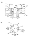
이어서, 본 실시예에 있어서의 그립핑 클로(101~103)를 도 9를 참조하여 설명한다. 도 9(a)는 그립핑 클로(101~103)의 단면도이고, 도 9(b)는 그립핑 클로(101~103)의 평면도이다. 그립핑 클로(101~103)는 지지핀(111~113)의 하단면(111a~113a)로부터 하방으로 돌출된 실린더 형상의 핀(101a~103a)과, 이 핀(101a~103a)을 동축상으로 둘러싸는 고무 등으로 형성된 탄성 실린더(101b~103b)를 포함한다. 핀(101a~103a)의 하단부 아래에는 이탈을 방지하기 위해 직경이 큰 헤드(101c~103c)가 형성되어 있다.Next, the gripping
그립핑 클로(101~103)의 탄성 실린더(101b~103b)에 있어서의 원형 외주면은 디스크(2)의 중심 구멍(2c)의 내주면(2d)에 접촉될 수 있는 디스크 접촉면이다. 그립핑 클로(101)(제 1 그립핑 클로)와 그립핑 클로(102)(제 2 그립핑 클로)의 축 길이는 그립핑 클로(103)(제 3 그립핑 클로)의 축 길이보다 길고, 그립핑될 디스크(2)의 내주면(2d)의 두께 이상이 되도록 구성된다. 본 실시예에 있어서, 그립핑 클로(101, 102)의 탄성 실린더(101b, 102b)의 길이는, 도 9(a)에 도시된 바와 같이, 적재된 상부 디스크(2(1))의 전체 내주면과 하부 디스크(2(2))의 내주면(2d)의 적어도 상부를 연장시킨 길이가 되도록 구성된다. 반대로, 그립핑 클로(103)의 탄 성 실린더(103b)의 길이는 그립핑될 디스크(2)의 내주면(2d)의 두께 이하가 되도록 구성되고, 본 실시예에 있어서는 상기 내주면(2d)의 두께보다 약간 작게 구성된다.The circular outer circumferential surface in the
도 9에 도시된 바와 같이, 그립핑 클로(101~103)는 두께 방향으로 적재되고, 반경 방향 외측으로 밀린 디스크 중에서 최상 디스크(2(1))의 중심 구멍(2c)에 삽입된다. 즉, 긴 그립핑 클로(101, 102)의 탄성 부재(101b, 102b)로 형성된 디스크 접촉면은 디스크 중심 구멍(2c)의 내주면으로 밀림으로써 유연하게 변형된다. 그러나, 디스크 접촉면에 있어서 디스크 중심 구멍(2c)으로부터 반대측으로 돌출된 부분(101e, 102e)[(101e)만 도시됨]은 유연하게 변형되지 않고, 디스크(2(1))의 후측을 통과하게 된다. 즉, 상기 부분(101e, 102e)은 그립핑될 상부 디스크(2(1))의 후측과 하부 디스크(2(2))의 전방측 사이의 갭을 통과한다. 또한, 탄성 실린더(101b, 102b)의 하단부(101f, 102f)[(101f)만 도시됨]는 하부 디스크(2(2))의 중심 구멍(2c)에 있어서의 내주면(2d)의 상측으로 밀린다. 한편, 짧은 그립핑 클로(103)의 디스크 접촉면은 최상 디스크(2(1))의 중심 구멍의 내주면으로만 밀린다.As shown in Fig. 9, the gripping
상부 디스크(2(1))는 3개의 그립핑 클로(101~103)에 의해 확실하게 그립핑된다. 또한, 상부 디스크(2(1))는 2개의 그립핑 클로(101, 102)에 있어서의 디스크 접촉면의 탄성 변형에 의해 확실하게 그립핑되어 상부 디스크(2(1))는 그립핑 클로(101, 102)로부터 디스크 두께 방향으로 이탈되지도 않는다. 2개의 긴 그립핑 클로(101, 102)의 디스크 접촉면에 있어서의 일부만이 하부 디스크(2(2))와 접촉하고, 하단부(101f, 102f)의 외측면의 폭은 중심 구멍(2c) 내경의 약 87%가 된다. 따라서, 그립핑 클로(101~103)가 리프팅되면 상부 디스크(2(1))만이 리프팅된다.The upper disk 2 (1) is reliably gripped by three gripping claws 101-103. Further, the upper disk 2 (1) is reliably gripped by the elastic deformation of the disk contact surfaces in the two
그립핑 클로(101~103)를 반경 방향으로 밀면 디스크 평면 방향에 있어서의 상부 디스크(2(1))의 위치는 3개의 그립핑 클로에 의해 고정되지만 하부 디스크(2(2))가 2개의 그립핑 클로(101, 102)에 접촉하기 때문에 하부 디스크(2(2))는 그립핑 클로(101, 102)에 의해 디스크 평면 방향으로 밀린다. 따라서, 하부 디스크(2(2))는 상부 디스크(2(1))에 대하여 비교적 약간 수평 방향으로 슬라이딩된다. 상부 디스크(2(1)) 및 하부 디스크(2(2))가 밀착되는 경우에도 하부 디스크(2(2))가 슬라이딩되어 상부 디스크(2(1))와 하부 디스크(2(2)) 사이의 에어를 통과함에 따라 밀착이 완화 또는 해제된다. 따라서, 상부 디스크(2(1))만을 확실하게 리프팅할 수 있다.When the gripping
또한, 3개의 그립핑 클로(101~103)의 디스크 접촉면은 탄성 실린더(101b~103b)로 형성되기 때문에 디스크(2)가 그립핑될 때 디스크(2)가 손상되지 않는다는 장점이 있다.In addition, since the disk contact surfaces of the three
통상적으로, 그립핑 클로의 수는 3개이지만, 그립핑 클로의 수는 4개 이상이 될 수 있다. 그립핑 클로의 수가 4개 이상이면 긴 그립핑 클로와 짧은 그립핑 클로의 수와 배치는 예컨대, 중심 구멍 등의 직경을 포함하지 않는 내주면의 1/2배 이하로 긴 그립핑 클로를 배치함으로써 적절하게 설정된다. 즉, 긴 그립핑 클로 사이의 거리가 중심 구멍의 직경보다 작게 되도록 긴 그립핑 클로를 배치한다.Typically, the number of gripping claws is three, but the number of gripping claws may be four or more. If the number of gripping claws is four or more, the number and arrangement of the long gripping claws and the short gripping claws may be appropriate, for example, by arranging the long gripping claws to be 1/2 or less of the inner circumferential surface not including the diameter of the center hole or the like. Is set to. That is, the long gripping claws are arranged such that the distance between the long gripping claws is smaller than the diameter of the center hole.
(디스크 검출 기구)(Disk detection mechanism)
그립핑 장치(100)는 그립핑 클로(101~103)가 디스크(2)의 중심 구멍(2c)에 삽입될 때의 정지 위치(삽입량)를 제어하기 위한 디스크 검출 기구를 포함한다. 도 6 ~ 도 9를 참조하면, 본 실시예에 있어서의 디스크 검출 기구(140)는 포토 커플러(photo coupler)를 포함하는 디스크 검출기(142)와 디스크 검출 레버(141)를 구비하고 있다. 디스크 검출 레버(141)는 직선형의 메인부(141a)와 이 메인부(141)의 전단부로부터 하방을 향해 직각으로 벤딩된 전단부(141b)를 포함하는 L자형 레버이다. 메인부(141a)의 후단은 이 메인부(141a)의 후단이 상방/하방으로 자유롭게 회전될 수 있는 암 베이스(55a)의 상측에 부착된다. 디스크 검출 레버(141)의 메인부(141a)는 암 베이스(55a)의 상측에 배치되고, 메인부(141a)의 전단부(141b)는 암 베이스(55a) 상에 형성된 개구부(55d)를 통해 개구부(55d)의 후측으로부터 하방으로 돌출되어 있다. 메인부(141a)의 측면에는 수평으로 돌출된 검출 플레이트(141c)가 형성되어 있다. 디스크 검출기(142)의 검출 영역(142a)은 디스크 검출 레버(141)의 상방/하방 이동을 수반하는 검출 플레이트(141c)의 이동 궤적 상에 배치된다.The
디스크(2)가 그립핑되지 않으면 디스크 검출 레버(141)는 암 베이스(55a) 상에 수평으로 유지된다. 본 실시예에 있어서, 검출 플레이트(141c)는 디스크 검출기(142)의 검출 영역(142a) 내에 배치되고, 검출 영역(142a)을 통과하는 검출광이 차단된 "오프" 상태가 된다. 반송암(55)을 하강시킴으로써 디스크(2)의 중심 구멍(2c)에 그립핑 클로(101~103)가 삽입됨에 따라 디스크 검출 레버(141)의 전단부(141b)는 디스크(2)의 표면과 접촉하게 되고, 디스크 검출 레버(141)는 그립핑 클로(101~103)의 삽입에 따라 리프팅된다.If the
도 7 및 도 9(a)에 도시된 바와 같이, 그립핑 클로(101~103)를 디스크(2)의 중심 구멍(2c)에 완전히 삽입한 후, 그립핑 클로(101~103)를 지지하는 지지판(111~113)의 하단면(111a~113a)이 디스크(2)와 접촉하기 직전에 검출 플레이트(141c)는 검출 영역(142)으로부터 이탈되고, 디스크 검출기(142)는 "온" 위치로 시프팅된다. 따라서, 그립핑 클로(101~103)가 디스크(2)의 중심 구멍(2c)에 삽입되는 것이 검출된다.As shown in Figs. 7 and 9 (a), the gripping
(반송암과 타이밍 벨트의 연결 기구)(Connecting mechanism of carrier arm and timing belt)
도 7 및 도 9(a)에 도시된 바와 같이, 그립핑 클로(101~103)의 삽입 위치가 검출 기구(140)를 사용하여 제어되면 디스크 검출 레버(141)의 제조 에러, 디스크 검출 레버(141)의 부착 에러, 디스크 검출기(142)의 부착 에러, 및 디스크 검출기(142)의 검출 에러 등에 의해 그립핑 클로(101~103)가 디스크(2)의 중심 구멍(2c)에 완전히 삽입될 때 그립핑 클로(101~103)가 정밀하게 정지될 수 없는 경우가 있다. 삽입이 충분하지 않은 경우에 디스크(2)는 그립핑 클로(101~103)에 의해 그립핑될 수 없기 때문에 그립핑 결함이 발생할 가능성이 있다. 한편, 그립핑 클로(101~103)가 과도하게 삽입되면 그립핑 클로(101~103)가 부착되는 지지핀(111~113)의 하단면(111a~113a) 등이 디스크(2)의 표면과 접촉하게 되어 디스크(2)를 손상시켜서 어떤 경우에는 디스크가 파손될 가능성이 있다. 이러한 단점을 방지하지 위해, 본 실시예에서는 탄성 부재를 통한 리프팅 기구인 타이밍 벨트(64)와 반송암(55)이 연결되는 구조의 연결 기구가 사용된다.As shown in Figs. 7 and 9 (a), when the insertion position of the gripping
도 10(a)는 연결 기구부를 나타내는 부분 사시도이고, 도 10(b)는 연결 기구부의 분해 사시도이다. 도 7과 도 10을 참조하면, 스프링 부재(151)를 통해 타이밍 벨트(64)에 고정된 벨트 클립(152)에 반송암(55)이 연결된다. 하방을 대향하는 상면(153) 및 이 상면(153)으로부터 하방을 향해 수직으로 연장되는 실린더 형상의 그라운드 축(154)은 반송암(55)의 암 베이스(55a)의 후단에 형성된다. 벨트 클립(152)은 하측으로부터 암 베이스측의 상면(153)에 접촉될 수 없는 상단면(152a), 벨트 클립(152)을 통해 상단면(152a)으로부터 연장되는 축 구멍(152b), 및 타이밍 벨트(64)에 고정적으로 연결된 고정부(152c)를 포함한다.Fig. 10 (a) is a partial perspective view showing the coupling mechanism part, and Fig. 10 (b) is an exploded perspective view of the coupling mechanism part. 7 and 10, the
그라운드 축(154)이 벨트 클립(152)의 축 구멍(152b)을 통과하는 암 베이스(55a)의 후단에 벨트 클립(152)이 부착되고, 벨트 클립(152)의 상단면(152a)은 하측으로부터 상면(153)과 접촉한다. 따라서, 반송암(55)은 그라운드 축(154), 축 구멍(152b), 상면(153), 및 상단면(152a)을 포함하는 지지부를 통해 타이밍 벨트(64)에 고정된 벨트 클립에 대하여 상방으로 이동될 수 있다. 즉, 반송암(55)은 그립핑 클로(101~103)가 디스크(2)의 중심 구멍(2c)으로부터 당겨지는 방향으로 이동될 수 있다.The
하측으로부터 스프링 부재(151)를 수납하는 홈(152d)은 벨트 클립(152)의 하면상에 축 구멍(152b)로부터 전방에 배치된 파트내에 형성된다. 스프링 부재(151)는 암 베이스(55a)의 후단에 형성된 스프링 행어(spring hanger)(155)에 부착되어 벨트 클립(152)을 항상 상방으로 바이어싱한다. 따라서, 스프링 부재(151)에 의해 벨트 클립(152)으로 암 베이스(55a)를 밀어서 암 베이스(55a)의 상방으로의 이동이 차단된다.The
타이밍 벨트(64)가 리프팅 모터(56)에 의해 구동(도 5 참조)되면 타이밍 벨 트(64)에 고정된 벨트 클립(152)은 일체로 리프팅된다. 과도한 부하가 인가되지 않으면 암 베이스(55a)는 스프링 부재(151)의 스프링력에 의해 타이밍 벨트(64)에 고정된 벨트 클립(152)과 함께 일체로 수직 가이드 축(54)을 따라 리프팅된다.When the
여기서, 반송암(55)이 하강되어 그립핑 클로(101~103)의 전단에 배치된 그립핑 클로(101~103)가 디스크(2)의 중심 구멍(2c)에 삽입되면 그립핑 클로(101~103)를 지지하는 지지판(111~113)의 하단면(111a~113a)은 디스크(2)가 상기 디스크 검출 기구(140)에 의해 검출되기 전에 디스크(2)의 표면과 충돌하는 것으로 추측된다.Here, the
이 경우에는 과도한 부하가 반송암(55)에 일시적으로 인가되어 스프링 부재(151)가 탄성적으로 변형되어 상/하 방향으로 밀린다. 따라서, 충돌력은 스프링 부재(151)의 탄성 변형에 의해 완화된다. 그 이후에, 벨트 클립(152)이 하강되면 반송암(55)은 스프링 부재(151)가 탄성적으로 변형되기 때문에 하강되지 않고 그 위치가 유지된다. 따라서, 디스크(2)가 과도하게 밀려서 파손되는 등의 단점이 방지될 수 있다.In this case, an excessive load is temporarily applied to the
디스크의 중심 구멍으로의 그립핑 클로(101~103)의 삽입량은 예컨대, 제조 에러, 구성 요소의 제조 에러, 부착 에러 등에 의해 야기된 디스크 검출 기구(140)의 검출 에러[그립핑 클로(101~103)의 정지 위치의 어긋남]를 고려하여 약간 충분하게 되도록 구성된다. 따라서, 그립핑 클로(101~103)의 디스크 그립핑 결함을 방지할 수 있다. 또한, 그립핑 클로(101~103)가 부착된 지지핀(111~113)(그립핑 부재)이 그립핑 클로(101~103)를 삽입하는 디스크의 표면(2b)과 접촉하면 탄성 부재 인 스프링 부재(151)가 탄성적으로 변형됨에 따라 디스크(2)에 인가된 충돌력이 완화된다. 또한, 지지핀(111~113)이 디스크(2)와 접촉된 후, 스프링 부재(151)는 탄성적으로 변형되어 상/하 방향으로 밀림에 따라 반송암(55)은 삽입 방향으로 더 이동되지 않는다. 따라서, 디스크(2)는 지지판(111~113)에 의해 손상되지 않는다.The insertion amount of the gripping
또한, 본 실시예에서는 그립핑 클로(101~103)를 지지하는 반송암(55)은 리프팅 기구인 타이밍 벨트(64)에 대하여 이동이 가능하게 연결되고, 항상 스프링 부재(151)에 의해 이동이 차단된다. 대안으로서, 예컨대, 그립핑 클로(101~103)의 지지핀(111~113)이 형성된 회전 플레이트(121~123)가 회전 중심축(131~133)에 대하여 상/하 방향으로 이동 가능하게 부착되어 있고, 헬리컬 압축 스프링(helical compressive spring) 등의 탄성 부재에 의해 상측으로부터 회전 플레이트(121~123)의 이동이 차단되면, 반송암(55)이 삽입 방향으로 이동되더라도 지지핀(111~113)이 디스크(2)와 접촉한 후 탄성 부재가 상/하 방향으로 탄성적으로 변형됨에 따라 지지핀(111~113)은 삽입 방향으로 더 이동되지 않는다. 다른 예시적 실시형태에 의하면, 지지핀(111~113)은 회전 플레이트(121~123)로부터 분리된 구성요소가 되도록 구성되고, 지지핀(111~113)은 스프링 부재를 통해 회전 플레이트(121~123)에 부착될 수 있다.In addition, in this embodiment, the
(디스크 그립핑 동작)(Disk Gripping Action)
도 11은 상기 구조를 갖는 디스크 이송 유닛(6)에 의해 수행되는 디스크 그립핑 동작을 나타낸 개략 플로우챠트이다.Fig. 11 is a schematic flowchart showing the disc gripping operation performed by the
예컨대, 블랭크 디스크 스태커(11)에 저장된 블랭크 디스크(2A)가 다른 부로 반송되도록 그립핑되고 리프팅되는 경우를 설명할 것이다. 이 경우에 있어서, 반송암(55)의 위치는 제어 유닛(7)의 제어하에 블랭크 디스크 스태커(11) 바로 위의 소정 위치가 되도록 결정된다.For example, a case will be described in which the
반송암(55) 내에 설치된 그립핑 장치(100)의 전자 솔레노이드(126)가 온이 된다(스텝 ST1). 전자 솔레노이드가 "온"으로 시프팅되고, 그 작동 로드(126a)가 당겨지면, 작동 로드(126a)의 이동은 L자형 링크를 통해 회전 플레이트(121)로 전달됨에 따라 회전 플레이트(121)는 도 8에 도시된 화살표(R2) 방향으로 소정 각도로 회전된다. 나머지 회전 플레이트(122, 123)가 동일 방향, 동일 각도로 회전되면 3개의 회전 플레이트(121~123)의 지지암(121c~123c)의 전단부에 부착된 그립핑 클로(101~103)가 각각 서로 접근하는 방향으로 이동함에 따라 디스크(2A)의 중심 구멍(2c)에 삽입되도록 그립핑 클로가 집중된다.The
그 이후에, 반송암을 리프팅하는 모터(56)가 구동되어 반송암(55)의 하강 동작이 개시된다(스텝 ST2). 반송암(55)이 하강되어 최상 블랭크 디스크(2A)에 접근하게 되면 반송암(55)에 내장된 디스크 검출 기구(140)의 검출 레버(141)는 블랭크 디스크(2A)의 표면과 접촉된다. 이어서, 검출 레버(141)는 반송암(55)의 하강과 함께 상방으로 각각 이동하고, 검출 레버(141)의 검출 플레이트(141c)가 디스크 검출기(142)의 검출 영역(142a)으로부터 이탈됨에 따라 디스크 검출기(142)는 "온"으로 시프팅된다(스텝 ST3). 반송암(55)이 소정 거리만큼 하강하여 정지되고, 반송암(55) 내에 배치된 그립핑 장치(100)의 그립핑 클로(101~103)가 블랭크 디스크(2A)의 중심 구멍(2c)에 삽입된다(스텝 ST4). 반송암을 리프팅하기 위한 모 터(56)로서 스텝핑 모터가 사용되면 예컨대, 반송암(55)의 위치는 스텝핑 모터의 스텝수에 의해 결정된다.After that, the
3개의 그립핑 클로(101~103)가 블랭크 디스크(2A)의 중심 구멍(2c)에 삽입되어 그립핑이 완료되는 상기 삽입 처리 이후에 중심 구멍(2c)에 삽입된 그립핑 클로(101~103)는 중심 구멍(2c)의 직경 방향 외측으로 밀려서 중심 구멍(2c)의 내주면(2d)으로 밀린다. 즉, 전자 솔레노이드(126)가 오프로 되어 작동 로드(126a)가 돌출 위치로 리턴된다(스텝 ST5). 따라서, L자형 링크를 통해 작동 로드(126a)에 연결된 회전 플레이트(121)는 헬리컬 확장 스프링(helical extension spring)(124)의 스프링력에 의해 도 8에 도시된 화살표(R1) 방향으로 회전되어 원래 위치로 리턴된다. 회전 플레이트(121)의 이동의 링키지(linkage)에 있어서, 나머지 2개의 회전 플레이트(122, 123)가 동일 방향, 동일 각도로 회전되어 원래 위치로 리턴된다. 따라서, 회전 플레이트(121~123)에 부착된 그립핑 클로(101~103)가 중심 구멍의 직경 방향 외측 및 블랭크 디스크(2A)의 중심 구멍의 내주면으로 밀리는 디스크 그립핑 상태가 된다.Three
상기 디스크 그립핑 처리가 완료된 후 그립핑 클로(101~103)를 통해 반송암(55)을 리프팅함으로써 그립핑된 블랭크 디스크(2a)가 리프팅되는 디스크 리프팅 처리가 수행된다(스텝 ST11~ST15).After the disc gripping process is completed, the disc lifting process in which the gripped
본 실시예의 디스크 리프팅 처리에 있어서, 반송암(55)이 소정 거리만큼 리프팅될 때까지, 즉, 그립핑 클로(101~103)가 삽입 방향의 반대 방향으로 소정 거리만큼 이동될 때까지 반송암(55)이 간헐적으로 리프팅된다. 즉, 소정 속도로 소정 거리만큼 반송암(55)을 리피팅하는 리프팅 동작과 소정 시간동안 반송암(55)을 정지시키는 정지 동작이 소정 회수로 반복된다(스텝 ST11~ST13). 반송암을 리프팅하는 모터(56)가 스텝핑 모터인 경우에 리프팅 거리는 스텝핑 모터의 스텝수에 의해 조종될 수 있다.In the disc lifting process of this embodiment, the
간헐적인 이동 처리가 수행된 후 블랭크 디스크(2A)가 디스크 검출 기구(140)의 출력에 의거하여 그립핑 클로(101~103)에 의해 그립핑되고 리프팅되었는지의 여부가 검출된다(스텝 ST14). 블랭크 디스크(2A)가 리프팅되면 디스크 검출 기구(140)의 검출 레버(141)는 이 검출 레버(141)가 리프팅된 블랭크 디스크(2A)에 의해 상방으로 이동하고, 디스크 검출기(142)가 "온" 상태가 된다. 따라서, 블랭크 디스크(2A)가 디스크 검출 기구(140)의 출력에 의거하여 그립핑 클로(101~103)에 의해 확실하게 그립핑되고 리프팅되었는지의 여부를 검출할 수 있다.After the intermittent movement processing is performed, it is detected whether or not the
블랭크 디스크(2A)가 리프팅되지 않으면 상기 처리는 스텝(ST1)으로 다시 리턴되고, 블랭크 디스크(2A)의 그립핑 및 리프팅 동작이 처음부터 다시 수행된다. 블랭크 디스크(2A)가 리프팅되면 간헐적인 이동 처리에 있어서의 반송암의 리프팅 속도보다 빠른 속도로 반송암(55)이 소정 높이의 위치로 연속적으로 리프팅되는 고속 연속 이동 처리가 수행된다(스텝 ST15).If the
본 실시예에서는 우선, 반송암(55)이 저속으로 간헐적으로 리프팅된다. 상기한 바와 같이, 반송암(55)은 스프링 부재(151)를 통해 리프팅 기구의 구동 부재인 타이밍 벨트(64)에 연결되어 있다. 디스크 검출 기구(140)의 동작에 의해 결정되는 그립핑 클로(101~103)의 삽입 정지 위치에 어긋남이 존재하면, 그립핑 클 로(101~103)는 스프링 부재(151)의 탄성 변형으로 인하여 디스크(2A)를 손상시키지 않고 디스크의 중심 구멍(2c)에 삽입되고, 그립핑 클로(101~103)가 부착된 지지핀(111~113)의 하단면(111a~113a)이 디스크의 표면과 접촉된다.In the present embodiment, first, the
반송암(55)은 스프링 부재(151)의 스프링력에 의해 디스크의 전방으로 밀린다. 즉, 블랭크 디스크(2A)는 상측으로부터 스프링 부재(151)의 스프링력에 의해 하측에 있는 블랭크 디스크(2A)로 밀린다. 이러한 방식으로 그립핑 클로(101~103)가 밀리는 경우에 상부 블랭크 디스크(2A)와 하부 블랭크 디스크(2A) 사이의 마찰력이 그립핑 클로(101~103)의 미는 힘보다 크면 블랭크 디스크(2A)는 수평 방향으로 이동될 수 없다. 따라서, 블랭크 디스크의 중심 구멍(2c)의 내주면(2d)이 3개의 그립핑 클로(101~103)에 의해 내측으로부터 확실하게 그립핑되지 않을 가능성이 있다.The
특히, 본 실시예에서는, 도 9에 도시된 바와 같이, 긴 그립핑 클로(101, 102)가 두 디스크의 내주면으로 연장되어 디스크가 상측으로부터 밀리면 디스크의 수평 방향으로의 밈에 의해 그립핑 클로(101, 102)가 개방되지 않을 가능성이 있다.In particular, in the present embodiment, as shown in Fig. 9, when the long
이러한 단점을 방지하기 위해 본 실시예의 그립핑 동작에 있어서 반송암(55)이 리프팅되는 경우에 우선, 간헐적인 리프팅 동작을 반복한다. 반송암(55)의 약간의 리프팅 및 정지 동작을 반복함으로써 블랭크 디스크(2A)의 미는 힘이 서서히 완화된다. 블랭크 디스크(2A)에 인가된 미는 힘은 어느 정도 또는 미는 힘이 소멸될 정도로 완화되면 그립핑 클로(101~103)에 의해 블랭크 디스크(2A)를 수평 방향으로 밀 수 있게 된다. 따라서, 도 9를 참조하여 상기한 바와 같이, 상부 블랭크 디스크(2A)와 하부 블랭크 디스크(2A)가 그립핑 클로(101~103)에 의해 각각 슬라이딩됨에 따라 상부 블랭크 디스크(2A)만이 그립핑된다. 이러한 간헐적인 이동 처리에 의해 블랭크 디스크(2A)가 확실하게 그립핑되기 때문에 블랭크 디스크(2A)가 리프팅되는 동안 블랭크 디스크(2A)가 이탈하는 등의 단점이 방지될 수 있다.In order to prevent this disadvantage, in the gripping operation of the present embodiment, first, the intermittent lifting operation is repeated when the
(라벨 인쇄기의 상세한 실시예)(Detailed Example of Label Printing Machine)
도 12 및 도 13은 각각 라벨 인쇄기(5)의 상세한 실시예를 나타낸 사시도 및 라벨 인쇄기의 인쇄기 트레이(81)를 나타낸 평면도이다. 이하, 라벨 인쇄기(5)의 구조를 도면을 참조하여 상세히 설명한다.12 and 13 are a perspective view showing a detailed embodiment of the
라벨 인쇄기(5)는 섀시(83) 및 이 섀시(83)의 후측에 있어서 좌우측 플레이트부 사이에서 수평으로 연장된 카트리지 가이드 축(84)을 포함하고, 잉크젯 헤드(도시 생략)가 내장된 헤드 카트리지(85)가 카트리지 가이드 축(84)을 따라 좌/우측 방향으로 왕복 운동할 수 있다. 카트리지 구동 기구는 좌/우측 방향으로 수평으로 연장된 타이밍 벨트(86) 및 이 타이밍 벨트(86)를 구동하는데 사용되는 카트리지 모터(87)를 포함한다.The
헤드 카트리지(85)에 내장된 잉크젯 헤드는 하방으로 배치된 노즐을 구비하고, 인쇄기 트레이(81)는 전/후 방향에 있어서 수평으로 잉크젯 헤드의 후면 위치를 왕복 운동할 수 있다. 인쇄기 트레이(81)는 전/후 방향에 있어서 수평으로 연장된 가이드 축(88)에 의해 지지되는 우측단, 및 전/후 방향에 있어서 수평으로 연장된 가이드 레일(89)에 의해 지지되는 좌측단을 구비하고, 가이드 레일(89)은 슬라 이딩 가능하다. 인쇄기 트레이(81)의 구동 기구는 전/후 방향에 있어서 수평으로 연장된 타이밍 벨트(90)와 이 타이밍 벨트(90)를 구동하는데 사용되는 트레이 모터(91)를 포함하는 구조를 갖는다.The inkjet head embedded in the
인쇄기 트레이(81)는 직사각형 플레이트의 전면에 디스크(2)를 로딩하는데 사용되는 섈로우 디프레션부(shallow depression part)(81a)를 포함한다. 상기 디프레션부(81a)의 중심부는 동일원에 내에서 60° 간격으로 배치된 수직 클로(92~94)를 포함한다. 하나의 수직 클로(94)는 반경 방향으로 이동 가능하고, 나머지 2개의 수직 클로(92, 93)는 고정 위치에 배치된다. 하나의 수직 클로(94)는 도시되지 않은 전자 솔레노이드 등의 구동 기구에 의해 이동되도록 구성된다.The
도 13에 도시된 바와 같이, 디스크(2)가 라벨측(2a)을 위로하여 상측으로부터 디프레션부(81a)로 떨어지면 3개의 수직 클로(92~94)가 디스크(2)의 중심 구멍(2c)에 삽입된다. 그 이후에, 수직 클로(94)가 반경 방향 외측으로 약간 이동되면 3개의 수직 클로(92~94)는 내측으로부터 디스크(2)의 중심 구멍(2c)의 내주면으로 밀린다. 따라서, 디스크(2)는 인쇄기 트레이(81) 내에 유지된다. 인쇄기 트레이는 트레이 모터(91)를 구동함으로써 잉크젯 헤드의 인쇄 영역으로 이동되어 가이드 축(88)을 따라 후면으로 인쇄기 트레이(81)가 이동될 수 있다. 그 이후에, 잉크젯 헤드에 의해 디스크(2)의 인쇄측상에 인쇄가 수행될 수 있다.As shown in Fig. 13, when the
본 발명은 상기 실시형태에 한정되지 않고, 다양한 수정이 이루어질 수 있다. 예컨대, 실린더형의 핀(101a~103a)과 이 핀(101a~103a)을 집중적으로 둘러싸는 고무로 이루어진 탄성 실린더(101b~103b) 등이 사용되는 경우가 본 발명의 예시적 인 실시형태에 개시되어 있지만, 최상 디스크만을 리프팅할 수 있다면 핀이 탄성 실린더(101b~103b) 없이 디스크를 직접 그립핑하는 기구가 사용될 수 있다. 그러나, 실리콘 고무 등의 탄성 부재가 사용되면 디스크의 그립핑 또는 반송에 있어서 그립핑이 향상될 수 있다.The present invention is not limited to the above embodiment, and various modifications can be made. For example, a case in which
또한, 상기 실시형태에 있어서, 모든 그립핑 클로(101~103)가 중심측으로 이동되는 경우가 제시되어 있지만, 특허문헌 2에서와 마찬가지로, 항상 최상 디스크를 그립핑 및 리프팅할 수 있다면 오직 하나의 그립핑 클로가 중심측으로 이동될 수 있다.Further, in the above embodiment, the case where all the
도 1은 본 발명의 예시적 실시형태에 의한 CD 퍼블리셔(CD publisher)의 구조를 나타낸 개략도이다.1 is a schematic diagram illustrating a structure of a CD publisher according to an exemplary embodiment of the present invention.
도 2는 CD 퍼블리셔의 외관의 상세한 실시예를 나타낸 사시도이다.2 is a perspective view showing a detailed embodiment of the appearance of the CD publisher.
도 3은 도어가 개방된 상태에 있는 CD 퍼블리셔의 사시도이다.3 is a perspective view of the CD publisher with the door open.
도 4는 CD 퍼블리셔의 내부 구조를 나타낸 사시도이다.4 is a perspective view showing the internal structure of a CD publisher.
도 5는 CD 퍼블리셔의 디스크 이송 유닛을 나타낸 사시도이다.5 is a perspective view showing the disc transfer unit of the CD publisher.
도 6은 디스크 이송 유닛의 반송암의 분해 사시도이다.6 is an exploded perspective view of the transfer arm of the disc transfer unit.
도 7은 디스크 이송 유닛의 그립핑 장치를 나타낸 측면도이다.7 is a side view showing the gripping device of the disc transfer unit.
도 8은 그립핑 장치의 평면도이다.8 is a plan view of the gripping device.
도 9는 그립핑 장치의 그립핑 클로(gripping claw)의 단면도와 평면도이다.9 is a cross-sectional view and a plan view of a gripping claw of the gripping device.
도 10은 반송암과 타이밍 벨트의 연결 기구를 나타낸 사시도와 분해 사시도이다.10 is a perspective view and an exploded perspective view showing a coupling mechanism between the carrier arm and the timing belt.
도 11은 디스크 이송 유닛의 디스크 그립핑 동작을 나타낸 개략 플로우챠트이다.11 is a schematic flowchart showing a disc gripping operation of the disc transfer unit.
도 12는 CD 퍼블리셔의 인쇄기를 나타낸 사시도이다.12 is a perspective view showing a printing press of the CD publisher.
도 13은 인쇄기의 인쇄기 트레이를 나타낸 평면도이다.Fig. 13 is a plan view showing a printer tray of the printer.
Claims (7)
Applications Claiming Priority (2)
| Application Number | Priority Date | Filing Date | Title |
|---|---|---|---|
| JP2006136170A JP2007310920A (en) | 2006-05-16 | 2006-05-16 | Disc gripping mechanism |
| JPJP-P-2006-136170 | 2006-05-16 |
Related Parent Applications (1)
| Application Number | Title | Priority Date | Filing Date |
|---|---|---|---|
| KR1020070047813A Division KR20070111387A (en) | 2006-05-16 | 2007-05-16 | Disc gripping device |
Publications (2)
| Publication Number | Publication Date |
|---|---|
| KR20080098351A true KR20080098351A (en) | 2008-11-07 |
| KR100946687B1 KR100946687B1 (en) | 2010-03-12 |
Family
ID=38328454
Family Applications (2)
| Application Number | Title | Priority Date | Filing Date |
|---|---|---|---|
| KR1020070047813A Ceased KR20070111387A (en) | 2006-05-16 | 2007-05-16 | Disc gripping device |
| KR1020080104627A Expired - Fee Related KR100946687B1 (en) | 2006-05-16 | 2008-10-24 | Disc gripping device |
Family Applications Before (1)
| Application Number | Title | Priority Date | Filing Date |
|---|---|---|---|
| KR1020070047813A Ceased KR20070111387A (en) | 2006-05-16 | 2007-05-16 | Disc gripping device |
Country Status (6)
| Country | Link |
|---|---|
| US (1) | US7789442B2 (en) |
| EP (3) | EP1858013B1 (en) |
| JP (1) | JP2007310920A (en) |
| KR (2) | KR20070111387A (en) |
| CN (1) | CN101075451B (en) |
| DE (1) | DE602007008316D1 (en) |
Families Citing this family (23)
| Publication number | Priority date | Publication date | Assignee | Title |
|---|---|---|---|---|
| JP4375425B2 (en) * | 2007-04-05 | 2009-12-02 | セイコーエプソン株式会社 | Media transport mechanism, media processing apparatus including the same, and media transport method |
| US20100199293A1 (en) * | 2008-01-07 | 2010-08-05 | Hung-Jui Lin | Inclinable pick-and-place head of disc pick-and-place device |
| JP2009277340A (en) * | 2008-04-18 | 2009-11-26 | Seiko Epson Corp | Disk conveyance mechanism of disk processing apparatus, and disk processing apparatus |
| JP5309678B2 (en) * | 2008-05-07 | 2013-10-09 | セイコーエプソン株式会社 | Disk processing apparatus and disk processing apparatus control method |
| JP5329854B2 (en) * | 2008-06-25 | 2013-10-30 | ティアック株式会社 | Optical disc apparatus and optical disc processing system having the same |
| JP5329853B2 (en) * | 2008-06-25 | 2013-10-30 | ティアック株式会社 | Optical disc apparatus and optical disc processing system having the same |
| JP2010123184A (en) * | 2008-11-19 | 2010-06-03 | Teac Corp | Disk holding device and disk processing device |
| JP5196164B2 (en) | 2008-11-19 | 2013-05-15 | ティアック株式会社 | Disc gripping device and disc processing device |
| US8607259B2 (en) | 2010-05-14 | 2013-12-10 | Ricoh Company, Ltd. | Disk laminate, disk cartridge, disk loading/unloading mechanism, disk conveying device, disk conveying mechanism, and thin disk driving system |
| US9090421B2 (en) | 2010-10-28 | 2015-07-28 | Panasonic Intellectual Property Management Co., Ltd. | Optical disk retrieval device and method |
| US8585115B2 (en) * | 2011-10-07 | 2013-11-19 | Varian Semiconductor Equipment Associates, Inc. | Method and apparatus for lifting a horizontally-oriented substrate from a cassette |
| JP5874294B2 (en) * | 2011-10-13 | 2016-03-02 | セイコーエプソン株式会社 | Media transport mechanism, control method of media transport mechanism, and media processing apparatus |
| JP5967582B2 (en) * | 2012-06-04 | 2016-08-10 | パナソニックIpマネジメント株式会社 | Disk unit |
| JP5927537B2 (en) | 2012-06-04 | 2016-06-01 | パナソニックIpマネジメント株式会社 | Disk unit |
| JP5909701B2 (en) * | 2012-06-15 | 2016-04-27 | パナソニックIpマネジメント株式会社 | Disk unit |
| JP5942201B2 (en) * | 2012-06-22 | 2016-06-29 | パナソニックIpマネジメント株式会社 | Disk unit |
| JP2014002831A (en) * | 2013-09-04 | 2014-01-09 | Teac Corp | Disk holding device and disk processing device |
| JP5866626B1 (en) * | 2014-08-05 | 2016-02-17 | パナソニックIpマネジメント株式会社 | Disk device and disk separation method |
| JP5920425B2 (en) * | 2014-09-01 | 2016-05-18 | セイコーエプソン株式会社 | Media transport mechanism and media processing apparatus provided with the same |
| US9799367B1 (en) * | 2016-09-23 | 2017-10-24 | Futurewei Technologies, Inc. | Multiple disk loader apparatus |
| CN114283855B (en) * | 2020-09-27 | 2024-06-07 | 上海强然数码科技有限公司 | Storage system |
| CN113618713B (en) * | 2021-07-29 | 2024-05-17 | 武汉光忆科技有限公司 | Disk taking device capable of selectively grabbing multiple optical disks, disk taking device and disk taking method |
| CN116061028B (en) * | 2023-03-02 | 2023-06-13 | 湖南金岭机床科技集团有限公司 | Carrier plate positioning device of multi-column high-precision polishing machine |
Family Cites Families (26)
| Publication number | Priority date | Publication date | Assignee | Title |
|---|---|---|---|---|
| US3416805A (en) * | 1965-10-20 | 1968-12-17 | James L.D. Morrison | Record changer spindle |
| JP3384002B2 (en) * | 1992-01-24 | 2003-03-10 | ソニー株式会社 | Disc table and recording and / or reproducing apparatus |
| US5485436A (en) * | 1993-05-24 | 1996-01-16 | National Film Board Of Canada | System and method for accessing information on stored optical discs |
| JPH09320158A (en) | 1996-05-27 | 1997-12-12 | Pioneer Electron Corp | Disk-chucking mechanism |
| DE19623125A1 (en) * | 1996-06-10 | 1997-12-11 | Eastman Kodak Co | Device for removing a plate-shaped object from a plate holder |
| US5873692A (en) * | 1996-11-15 | 1999-02-23 | Costas; Dan N. | CD picker |
| JP3690027B2 (en) | 1997-01-10 | 2005-08-31 | ソニー株式会社 | Disk drive device and disk holding mechanism |
| JPH11296942A (en) * | 1998-04-09 | 1999-10-29 | Sony Corp | Disk chuck device |
| JP2000117206A (en) | 1998-10-12 | 2000-04-25 | Shimada Phys & Chem Ind Co Ltd | Donut type substrate cleaning equipment |
| JP2000317873A (en) | 1999-05-07 | 2000-11-21 | Sony Corp | Handling apparatus and handling method for polymer material disk substrate |
| US6802070B2 (en) | 2000-06-09 | 2004-10-05 | Primera Technology, Inc. | Compact disc transporter |
| JP4450955B2 (en) * | 2000-06-26 | 2010-04-14 | オリンパス株式会社 | Optical disk carrier |
| JP3672097B2 (en) | 2000-09-21 | 2005-07-13 | 松下電器産業株式会社 | Disk unit |
| US6697321B2 (en) | 2000-09-21 | 2004-02-24 | Matsushita Electric Industrial Co., Ltd | Disc apparatus |
| JP2003257084A (en) | 2002-02-28 | 2003-09-12 | Teac Corp | Optical disk clamp mechanism and optical disk dubbing system |
| JP3852367B2 (en) * | 2002-05-14 | 2006-11-29 | ティアック株式会社 | Disk unit |
| US6760052B2 (en) * | 2002-06-03 | 2004-07-06 | Primera Technology, Inc. | CD recorder and printer |
| DE10313552A1 (en) | 2003-03-26 | 2004-11-18 | Dr. Schenk Gmbh Industriemesstechnik | Rotary carrier used for automatic handling of e.g. digital versatile disc, has turntable component with penetrating hole for centering body |
| JP4240374B2 (en) * | 2003-07-04 | 2009-03-18 | 株式会社データンク | Disc transfer apparatus and method, and multi-disc processing apparatus using the same |
| JP3849874B2 (en) * | 2003-10-08 | 2006-11-22 | ソニー株式会社 | Chucking mechanism for disk recording medium and disk drive apparatus using the mechanism |
| KR100580637B1 (en) * | 2003-10-18 | 2006-05-16 | (주)나노스토리지 | Disk I / O Device with Stacked Optical Disk Array Structure |
| JP2005228374A (en) | 2004-02-10 | 2005-08-25 | Sony Corp | Disc chuck device |
| US7360812B2 (en) * | 2004-03-27 | 2008-04-22 | Anton Vasile Ionescu | Automatic device, equipment and methods for handling objects |
| DE102005049843A1 (en) | 2004-10-18 | 2006-04-20 | Adr Ag | Lifting device for disk like CD or DVD, comprising lifting element and holding element |
| JP4085334B2 (en) | 2004-11-09 | 2008-05-14 | 株式会社デンソー | Dual power supply type vehicle power supply |
| US7540237B2 (en) * | 2005-01-19 | 2009-06-02 | Kubin Dale K | Printer |
-
2006
- 2006-05-16 JP JP2006136170A patent/JP2007310920A/en not_active Withdrawn
-
2007
- 2007-04-27 US US11/790,778 patent/US7789442B2/en not_active Expired - Fee Related
- 2007-05-10 EP EP07009387A patent/EP1858013B1/en not_active Ceased
- 2007-05-10 EP EP11151580A patent/EP2317512B1/en not_active Ceased
- 2007-05-10 DE DE602007008316T patent/DE602007008316D1/en active Active
- 2007-05-10 EP EP08022208A patent/EP2034478B1/en not_active Ceased
- 2007-05-16 KR KR1020070047813A patent/KR20070111387A/en not_active Ceased
- 2007-05-16 CN CN2007101041193A patent/CN101075451B/en not_active Expired - Fee Related
-
2008
- 2008-10-24 KR KR1020080104627A patent/KR100946687B1/en not_active Expired - Fee Related
Also Published As
| Publication number | Publication date |
|---|---|
| EP2317512A1 (en) | 2011-05-04 |
| EP2034478A2 (en) | 2009-03-11 |
| CN101075451A (en) | 2007-11-21 |
| EP1858013A2 (en) | 2007-11-21 |
| EP1858013A3 (en) | 2008-07-02 |
| EP2317512B1 (en) | 2012-05-09 |
| US7789442B2 (en) | 2010-09-07 |
| JP2007310920A (en) | 2007-11-29 |
| EP2034478B1 (en) | 2011-08-24 |
| EP1858013B1 (en) | 2010-08-11 |
| EP2034478A3 (en) | 2009-03-18 |
| KR100946687B1 (en) | 2010-03-12 |
| DE602007008316D1 (en) | 2010-09-23 |
| CN101075451B (en) | 2010-09-01 |
| KR20070111387A (en) | 2007-11-21 |
| US20070267881A1 (en) | 2007-11-22 |
Similar Documents
| Publication | Publication Date | Title |
|---|---|---|
| KR100946687B1 (en) | Disc gripping device | |
| US7878565B2 (en) | Disc picking device and disc processing apparatus having the same | |
| US8245247B2 (en) | Medium transporting unit and medium processing apparatus | |
| US9449639B2 (en) | Medium transporting unit and medium processing apparatus | |
| US8954999B2 (en) | Adjustable medium holding unit and medium processing apparatus | |
| JP4918888B2 (en) | Media processing apparatus and control method thereof | |
| US7887282B2 (en) | Media transportation mechanism and media processing device having the media transportation mechanism | |
| JP5234137B2 (en) | Disk transport device and control method thereof | |
| JP2007310923A (en) | Disc gripping method | |
| JP2007310922A (en) | Disc gripping mechanism | |
| JP4930221B2 (en) | Control method of media transport mechanism and media processing apparatus | |
| JPH05189855A (en) | Disk drive device |
Legal Events
| Date | Code | Title | Description |
|---|---|---|---|
| A107 | Divisional application of patent | ||
| A201 | Request for examination | ||
| PA0107 | Divisional application |
St.27 status event code: A-0-1-A10-A16-div-PA0107 St.27 status event code: A-0-1-A10-A18-div-PA0107 |
|
| PA0201 | Request for examination |
St.27 status event code: A-1-2-D10-D11-exm-PA0201 |
|
| PG1501 | Laying open of application |
St.27 status event code: A-1-1-Q10-Q12-nap-PG1501 |
|
| E902 | Notification of reason for refusal | ||
| PE0902 | Notice of grounds for rejection |
St.27 status event code: A-1-2-D10-D21-exm-PE0902 |
|
| T11-X000 | Administrative time limit extension requested |
St.27 status event code: U-3-3-T10-T11-oth-X000 |
|
| E601 | Decision to refuse application | ||
| PE0601 | Decision on rejection of patent |
St.27 status event code: N-2-6-B10-B15-exm-PE0601 |
|
| T11-X000 | Administrative time limit extension requested |
St.27 status event code: U-3-3-T10-T11-oth-X000 |
|
| J201 | Request for trial against refusal decision | ||
| PJ0201 | Trial against decision of rejection |
St.27 status event code: A-3-3-V10-V11-apl-PJ0201 |
|
| AMND | Amendment | ||
| P11-X000 | Amendment of application requested |
St.27 status event code: A-2-2-P10-P11-nap-X000 |
|
| P13-X000 | Application amended |
St.27 status event code: A-2-2-P10-P13-nap-X000 |
|
| PB0901 | Examination by re-examination before a trial |
St.27 status event code: A-6-3-E10-E12-rex-PB0901 |
|
| B701 | Decision to grant | ||
| PB0701 | Decision of registration after re-examination before a trial |
St.27 status event code: A-3-4-F10-F13-rex-PB0701 |
|
| GRNT | Written decision to grant | ||
| PR0701 | Registration of establishment |
St.27 status event code: A-2-4-F10-F11-exm-PR0701 |
|
| PR1002 | Payment of registration fee |
Fee payment year number: 1 St.27 status event code: A-2-2-U10-U11-oth-PR1002 |
|
| PG1601 | Publication of registration |
St.27 status event code: A-4-4-Q10-Q13-nap-PG1601 |
|
| FPAY | Annual fee payment |
Payment date: 20130227 Year of fee payment: 4 |
|
| PR1001 | Payment of annual fee |
Fee payment year number: 4 St.27 status event code: A-4-4-U10-U11-oth-PR1001 |
|
| FPAY | Annual fee payment |
Payment date: 20140220 Year of fee payment: 5 |
|
| PR1001 | Payment of annual fee |
Fee payment year number: 5 St.27 status event code: A-4-4-U10-U11-oth-PR1001 |
|
| FPAY | Annual fee payment |
Payment date: 20150224 Year of fee payment: 6 |
|
| PR1001 | Payment of annual fee |
Fee payment year number: 6 St.27 status event code: A-4-4-U10-U11-oth-PR1001 |
|
| FPAY | Annual fee payment |
Payment date: 20160219 Year of fee payment: 7 |
|
| PR1001 | Payment of annual fee |
Fee payment year number: 7 St.27 status event code: A-4-4-U10-U11-oth-PR1001 |
|
| R18-X000 | Changes to party contact information recorded |
St.27 status event code: A-5-5-R10-R18-oth-X000 |
|
| FPAY | Annual fee payment |
Payment date: 20170221 Year of fee payment: 8 |
|
| PR1001 | Payment of annual fee |
Fee payment year number: 8 St.27 status event code: A-4-4-U10-U11-oth-PR1001 |
|
| FPAY | Annual fee payment |
Payment date: 20180220 Year of fee payment: 9 |
|
| PR1001 | Payment of annual fee |
Fee payment year number: 9 St.27 status event code: A-4-4-U10-U11-oth-PR1001 |
|
| FPAY | Annual fee payment |
Payment date: 20190219 Year of fee payment: 10 |
|
| PR1001 | Payment of annual fee |
Fee payment year number: 10 St.27 status event code: A-4-4-U10-U11-oth-PR1001 |
|
| FPAY | Annual fee payment |
Payment date: 20200219 Year of fee payment: 11 |
|
| PR1001 | Payment of annual fee |
Fee payment year number: 11 St.27 status event code: A-4-4-U10-U11-oth-PR1001 |
|
| PC1903 | Unpaid annual fee |
Not in force date: 20210304 Payment event data comment text: Termination Category : DEFAULT_OF_REGISTRATION_FEE St.27 status event code: A-4-4-U10-U13-oth-PC1903 |
|
| PC1903 | Unpaid annual fee |
Ip right cessation event data comment text: Termination Category : DEFAULT_OF_REGISTRATION_FEE Not in force date: 20210304 St.27 status event code: N-4-6-H10-H13-oth-PC1903 |