JP5874294B2 - Media transport mechanism, control method of media transport mechanism, and media processing apparatus - Google Patents
Media transport mechanism, control method of media transport mechanism, and media processing apparatus Download PDFInfo
- Publication number
- JP5874294B2 JP5874294B2 JP2011225607A JP2011225607A JP5874294B2 JP 5874294 B2 JP5874294 B2 JP 5874294B2 JP 2011225607 A JP2011225607 A JP 2011225607A JP 2011225607 A JP2011225607 A JP 2011225607A JP 5874294 B2 JP5874294 B2 JP 5874294B2
- Authority
- JP
- Japan
- Prior art keywords
- media
- speed
- medium
- arm
- transport
- Prior art date
- Legal status (The legal status is an assumption and is not a legal conclusion. Google has not performed a legal analysis and makes no representation as to the accuracy of the status listed.)
- Expired - Fee Related
Links
- 230000007723 transport mechanism Effects 0.000 title claims description 58
- 238000000034 method Methods 0.000 title claims description 10
- 238000000926 separation method Methods 0.000 claims description 41
- 230000001174 ascending effect Effects 0.000 claims description 23
- 238000001514 detection method Methods 0.000 claims description 23
- 238000010030 laminating Methods 0.000 claims 2
- 239000002609 medium Substances 0.000 description 190
- 230000032258 transport Effects 0.000 description 119
- 230000007246 mechanism Effects 0.000 description 30
- 210000000078 claw Anatomy 0.000 description 19
- 238000001179 sorption measurement Methods 0.000 description 16
- 239000002131 composite material Substances 0.000 description 12
- 230000005540 biological transmission Effects 0.000 description 11
- 230000002093 peripheral effect Effects 0.000 description 7
- 238000010586 diagram Methods 0.000 description 5
- 230000007423 decrease Effects 0.000 description 4
- 230000004308 accommodation Effects 0.000 description 3
- 150000001875 compounds Chemical class 0.000 description 3
- 230000003247 decreasing effect Effects 0.000 description 2
- 238000013459 approach Methods 0.000 description 1
- 230000000903 blocking effect Effects 0.000 description 1
- 230000000694 effects Effects 0.000 description 1
- 238000003475 lamination Methods 0.000 description 1
- 230000003287 optical effect Effects 0.000 description 1
- 230000000630 rising effect Effects 0.000 description 1
- 239000006163 transport media Substances 0.000 description 1
Images


Classifications
-
- G—PHYSICS
- G11—INFORMATION STORAGE
- G11B—INFORMATION STORAGE BASED ON RELATIVE MOVEMENT BETWEEN RECORD CARRIER AND TRANSDUCER
- G11B17/00—Guiding record carriers not specifically of filamentary or web form, or of supports therefor
- G11B17/08—Guiding record carriers not specifically of filamentary or web form, or of supports therefor from consecutive-access magazine of disc records
- G11B17/10—Guiding record carriers not specifically of filamentary or web form, or of supports therefor from consecutive-access magazine of disc records with horizontal transfer to the turntable from a stack arranged with a vertical axis
-
- G—PHYSICS
- G11—INFORMATION STORAGE
- G11B—INFORMATION STORAGE BASED ON RELATIVE MOVEMENT BETWEEN RECORD CARRIER AND TRANSDUCER
- G11B23/00—Record carriers not specific to the method of recording or reproducing; Accessories, e.g. containers, specially adapted for co-operation with the recording or reproducing apparatus ; Intermediate mediums; Apparatus or processes specially adapted for their manufacture
- G11B23/38—Visual features other than those contained in record tracks or represented by sprocket holes the visual signals being auxiliary signals
- G11B23/40—Identifying or analogous means applied to or incorporated in the record carrier and not intended for visual display simultaneously with the playing-back of the record carrier, e.g. label, leader, photograph
Description
本発明は、CD(Compact Disc)、DVD(Digital Versatile Disc)またはBD(Blu−ray Disc)等のメディアを搬送するメディア搬送機構、このメディア搬送機構の制御方法、および、このメディア搬送機構を有するメディア処理装置に関する。 The present invention has a media transport mechanism for transporting media such as a CD (Compact Disc), a DVD (Digital Versatile Disc), or a BD (Blu-ray Disc), a control method for the media transport mechanism, and the media transport mechanism. The present invention relates to a media processing device.
従来、CDやDVD等のメディアに対してデータの書き込みとレーベル印刷とを行って、メディアを発行するCD/DVDパブリッシャー等のメディア処理装置が知られている(たとえば、特許文献1参照)。特許文献1に記載のメディア処理装置は、データ書き込み等の処理が行われていない未使用のメディアが積層されて収容されるブランクメディアスタッカーと、処理済みのメディアが積層されて収容される作成済みメディアスタッカーと、メディアを把持して搬送するメディア搬送機構とを備えている。 2. Description of the Related Art Conventionally, media processing apparatuses such as CD / DVD publishers that perform data writing and label printing on media such as CDs and DVDs and issue media are known (see, for example, Patent Document 1). The media processing apparatus described in Patent Document 1 is a blank media stacker that stores unused media that are not subjected to processing such as data writing, and a created media that stores processed media that are stacked. A media stacker and a media transport mechanism for gripping and transporting the media are provided.
メディア搬送機構は、昇降可能な搬送アームを備えており、搬送アームは、メディアの中心孔に挿入されるガイド部と、メディアの中心孔の側面に当接してメディアを把持する把持機構とを備えている。ガイド部は、円柱状に形成される基端部と、下側へ向かって次第に径が小さくなる円錐台状のガイド面部とから構成されており、基端部の下端にガイド面部が繋がっている。把持機構は、メディアの中心孔の側面に当接してメディアを把持する3個の把持爪を備えている。なお、CDおよびDVDの記録面側の中心孔の周辺には、記録面を保護するためのスタックリングと呼ばれる円形状の突起が形成されている。 The media transport mechanism includes a transport arm that can be moved up and down, and the transport arm includes a guide portion that is inserted into the center hole of the media, and a gripping mechanism that grips the media by contacting the side surface of the center hole of the media. ing. The guide portion is composed of a base end portion formed in a columnar shape and a truncated conical guide surface portion whose diameter gradually decreases toward the lower side, and the guide surface portion is connected to the lower end of the base end portion. . The gripping mechanism includes three gripping claws that touch the side surface of the center hole of the media to grip the media. A circular projection called a stack ring for protecting the recording surface is formed around the central hole on the recording surface side of the CD and DVD.
特許文献1に記載のメディア処理装置では、処理前のメディアが記録面を下側に向けた状態でブランクメディアスタッカーに積層されて収容されている。そのため、スタッカーの内部において、上側に配置されるメディアのスタックリングと、下側に配置されるメディアの記録面の反対側の面となる印刷面とが密着して、メディア間に吸着力が生じる場合がある。この場合、ブランクメディアスタッカーに積層されたメディアのうちの一番上の1枚のメディア(最上部のメディア)を搬送アームで持ち上げようとしたときに、直下のメディア(すなわち、上から2番目のメディア)が最上部のメディアとともに持ち上げられるおそれがある。2枚のメディアが吸着された状態で、搬送アームによってメディアが搬送されると、搬送先で不具合が生じる。そこで、特許文献1に記載のメディア処理装置では、搬送アームは、最上部のメディアに対して直下のメディアを移動させて最上部のメディアから分離するキックレバーを備えている。そのため、このメディア処理装置では、ブランクメディアスタッカーから最上部のメディア1枚のみを持ち上げて搬送することが可能である。 In the media processing device described in Patent Document 1, media before processing are stacked and accommodated on a blank media stacker with the recording surface facing downward. Therefore, inside the stacker, the stack ring of the media arranged on the upper side and the printing surface, which is the surface opposite to the recording surface of the media arranged on the lower side, are in close contact with each other, and an adsorption force is generated between the media. There is a case. In this case, when the uppermost one of the media stacked on the blank media stacker (the uppermost media) is lifted by the transport arm, the media immediately below (ie, the second media from the top) Media) may be lifted along with the top media. If the media is transported by the transport arm while the two media are adsorbed, a problem occurs at the transport destination. Therefore, in the media processing device described in Patent Document 1, the transport arm includes a kick lever that moves the media immediately below the top media to separate the media from the top media. Therefore, in this media processing apparatus, it is possible to lift and convey only one uppermost medium from the blank media stacker.
近年、メディアとして、CDやDVDに加え、BDが広く利用されるようになっている。BDの場合、記録面側の中心孔の周辺にスタックリングが形成されていないか、あるいは、スタックリングが形成されていても、その高さはCDやDVDのスタックリングの高さよりも低い。そのため、ブランクメディアスタッカーにBDが積層されて収容される場合、上側に配置されるBDの記録面と下側に配置されるBDの印刷面とが密着しやすくなる。上下に配置されるBDの記録面と印刷面とが密着すると、記録面と印刷面との間に空気が入りにくくなるため、ブランクメディアスタッカー内でBD間に生じる吸着力はCDやDVD間に生じる吸着力よりも大きくなる。 In recent years, BD has been widely used as a medium in addition to CD and DVD. In the case of BD, the stack ring is not formed around the central hole on the recording surface side, or the height of the stack ring is lower than the height of the stack ring of CD or DVD. For this reason, when the BDs are stacked and accommodated in the blank media stacker, the recording surface of the BD disposed on the upper side and the printing surface of the BD disposed on the lower side are easily adhered to each other. When the recording surface and the printing surface of the BD arranged above and below are in close contact with each other, it becomes difficult for air to enter between the recording surface and the printing surface, so the adsorption force generated between the BDs in the blank media stacker is between CD and DVD. It is greater than the resulting attractive force.
上述のように、特許文献1に記載のメディア処理装置では、搬送アームがキックレバーを備えているため、ブランクメディアスタッカー内に積層されて収容されるメディアがCDやDVDであれば、ブランクメディアスタッカー内でメディア間に吸着力が発生しても、最上部のメディアから直下のメディアを分離して落下させ、ブランクメディアスタッカーから最上部のメディア1枚のみを持ち上げて搬送することが可能である。しかしながら、ブランクメディアスタッカー内に積層されて収容されるメディアがBDである場合、BD間の吸着力は、CDやDVD間の吸着力よりも大きくなる。そのため、ブランクメディアスタッカー内に積層されて収容されるメディアがBDである場合にブランクメディアスタッカー内でメディア間に吸着力が生じると、最上部のメディアから直下のメディアをキックレバーで分離する際に、最上部のメディアが直下のメディアと一緒に搬送アームから落下するといった現象が起こることが本願発明者の検討によって明らかになった。 As described above, in the media processing apparatus described in Patent Document 1, since the transport arm includes the kick lever, if the media stacked and accommodated in the blank media stacker is a CD or DVD, the blank media stacker Even if an attracting force is generated between the media, it is possible to separate and drop the media directly below the top media and lift and transport only the top media from the blank media stacker. However, when the media stacked and accommodated in the blank media stacker is a BD, the adsorption force between BDs is larger than the adsorption force between CDs and DVDs. Therefore, when the media stacked and accommodated in the blank media stacker is a BD, if an adsorption force is generated between the media in the blank media stacker, when the media immediately below is separated from the top media by the kick lever It has been clarified by the inventor of the present application that a phenomenon occurs in which the uppermost medium falls from the transport arm together with the media immediately below.
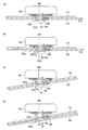
具体的には、本願発明者の検討によって、以下の現象が発生することが明らかになった。すなわち、図12(A)に示すように、把持爪108が最上部のメディア101を把持して持ち上げようとしたとき、最上部のメディア101に直下のメディア102が吸着されて、最上部のメディア101と一緒に直下のメディア102が搬送アーム105で持ち上げられた場合に、最上部のメディア101から直下のメディア102を分離するため、キックレバー106が直下のメディア102を蹴り出すと、直下のメディア102には、キックレバー106の蹴り出し方向に力F10が作用して、直下のメディア102は、キックレバー106の蹴り出し方向へ移動する。すると、図12(B)に示すように、直下のメディア102の中心孔102aの側面がガイド部107のガイド面部107aに接触して、ガイド面部107aに沿った力F20が直下のメディア102に作用する。すると、直下のメディア102を吸着している最上部のメディア101にもガイド面部107aに沿った力F20が作用する。すると、図12(C)に示すように、最上部のメディア101と把持爪108との接触点を支点としたモーメントM10が2枚のメディア101、102に生じて、最上部のメディア101が把持爪108から外れ、2枚のメディア101、102が回転する。すると、図12(D)に示すように、最上部のメディア101が直下のメディア102と一緒に搬送アーム105から落下する。なお、最上部のメディア101が把持爪108から外れても最上部のメディア101がキックレバー106に引っ掛かって落下しない場合もあるが、この場合には、最上部のメディア101の搬送先で不具合が生じる。
Specifically, it has been clarified by the inventors that the following phenomenon occurs. That is, as shown in FIG. 12A, when the
そこで、本発明の課題は、メディアに形成されるスタックリングの高さが低く、または、メディアにスタックリングが形成されておらず、積層されたメディア間に生じる吸着力が大きい場合であっても、メディアを1枚のみ確実に搬送することが可能なメディア搬送機構、および、メディア搬送機構の制御方法を提案することにある。また、本発明の課題は、かかるメディア搬送機構、または、かかるメディア搬送機構の制御方法で制御されるメディア搬送機構を有するメディア処理装置を提案することにある。 Therefore, the problem of the present invention is that even when the stack ring formed on the medium is low in height, or the stack ring is not formed on the medium and the adsorption force generated between the stacked media is large. An object of the present invention is to propose a media transport mechanism capable of transporting only one medium reliably and a control method for the media transport mechanism. Another object of the present invention is to propose a media processing apparatus having such a media transport mechanism or a media transport mechanism controlled by a control method of the media transport mechanism.
上記の課題を解決するため、本発明のメディア搬送機構は、昇降可能な搬送アームを有し、積層されたメディアのうちの一番上の前記メディアである最上部メディアを前記搬送アームで把持して搬送するメディア搬送機構であって、前記搬送アームに搭載され、前記最上部メディアの中心孔の側面に当接して前記最上部メディアを把持する把持部材と、前記搬送アームに搭載され、前記把持部材によって把持される前記最上部メディアに吸着された前記最上部メディアの直下の前記メディアである直下メディアを前記最上部メディアに対して移動させて前記最上部メディアから分離する分離部材と、前記メディア搬送機構を制御する制御部と、を有し、前記搬送アームの上昇速度は、第1の速度と、前記第1の速度よりも遅い第2の速度とに切替可能となっており、前記直下メディアを前記最上部メディアから分離する方向へ移動するときの前記分離部材の移動速度は、第3の速度と、前記第3の速度よりも遅い第4の速度とに切替可能となっており、前記制御部は、特定条件下において、前記搬送アームの上昇速度を前記第1の速度から前記第2の速度に切り替えること、および、前記分離部材の移動速度を前記第3の速度から前記第4の速度に切り替えること、の少なくともいずれか一方を行うことを特徴とする。 In order to solve the above problems, the media transport mechanism of the present invention has a transport arm that can be moved up and down, and grips the uppermost medium, which is the top medium among the stacked media, with the transport arm. A medium conveying mechanism that conveys the uppermost medium, and that is mounted on the conveying arm and that is mounted on the conveying arm. A separation member that moves the lower medium, which is the medium immediately below the uppermost medium held by the uppermost medium held by a member, to the uppermost medium and separates it from the uppermost medium; and the medium A control unit that controls the transfer mechanism, and the ascending speed of the transfer arm is set to a first speed and a second speed that is slower than the first speed. The moving speed of the separating member when moving the direct medium in the direction separating the uppermost medium from the uppermost medium is a third speed and a fourth speed that is slower than the third speed. And the control unit switches the ascending speed of the transfer arm from the first speed to the second speed under a specific condition, and the moving speed of the separation member. At least one of switching from the third speed to the fourth speed is performed.
また、上記の課題を解決するため、本発明のメディア搬送機構の制御方法は、昇降可能な搬送アームを有し、積層されたメディアのうちの一番上の前記メディアである最上部メディアを前記搬送アームで把持して搬送するメディア搬送機構の制御方法であって、前記メディア搬送機構は、前記搬送アームに搭載され、前記最上部メディアの中心孔の側面に当接して前記最上部メディアを把持する把持部材と、前記搬送アームに搭載され、前記把持部材によって把持される前記最上部メディアに吸着された前記最上部メディアの直下の前記メディアである直下メディアを前記最上部メディアに対して移動させて前記最上部メディアから分離する分離部材と、を有し、前記搬送アームの上昇速度は、第1の速度と、前記第1の速度よりも遅い第2の速度とに切替可能となっており、前記直下メディアを前記最上部メディアから分離する方向へ移動するときの前記分離部材の移動速度は、第3の速度と、前記第3の速度よりも遅い第4の速度とに切替可能となっており、特定条件下において、前記搬送アームの上昇速度を前記第1の速度から前記第2の速度に切り替えること、および、前記分離部材の移動速度を前記第3の速度から前記第4の速度に切り替えること、の少なくともいずれか一方を行うことを特徴とする。 In order to solve the above-described problem, a control method for a media transport mechanism according to the present invention includes a transport arm that can be moved up and down, and the top media that is the top media among the stacked media is the top media. A method of controlling a media transport mechanism that grips and transports a transport arm, the media transport mechanism being mounted on the transport arm and gripping the top media by contacting a side surface of a central hole of the top media A gripping member that is mounted on the transfer arm, and a media immediately below the top media attracted by the top media that is gripped by the gripping member is moved relative to the top media. A separating member that separates from the uppermost medium, and the ascending speed of the transfer arm is a first speed and a second speed that is lower than the first speed. The moving speed of the separating member when moving the immediately lower medium in the direction of separating from the uppermost medium is a third speed and a third speed that is lower than the third speed. 4 can be switched to a speed of 4, and under a specific condition, the lifting speed of the transfer arm is switched from the first speed to the second speed, and the moving speed of the separating member is changed to the first speed. Switching from the speed of 3 to the fourth speed is performed.
本発明では、特定条件下において、搬送アームの上昇速度を第1の速度から第1の速度よりも遅い第2の速度に切り替えること、および、分離部材の移動速度を第3の速度から第3の速度よりも遅い第4の速度に切り替えること、の少なくともいずれか一方を行っている。最上部メディアに直下メディアが吸着されて、最上部メディアと一緒に直下メディアが搬送アームで持ち上げられた場合、最上部メディアと直下メディアとが一緒に持ち上げられてからの時間の経過に伴って、直下メディアに作用する自重の影響で、最上部メディアと直下メディアとの間に空気が入り込みやすくなり、最上部メディアと直下メディアとの吸着力が低下していく。 In the present invention, under a specific condition, the ascending speed of the transfer arm is switched from the first speed to the second speed that is slower than the first speed, and the moving speed of the separation member is changed from the third speed to the third speed. At least one of switching to a fourth speed that is slower than the first speed is performed. When the media directly below is picked up by the top media and the media directly lifted together with the media at the top, with the passage of time since the media top and media directly lifted together, Under the influence of the dead weight acting on the media directly below, air easily enters between the top media and the media directly below, and the adsorption force between the media on the top and the media directly below decreases.
そのため、本発明では、最上部メディアに直下メディアが吸着されて、最上部メディアと一緒に直下メディアが搬送アームで持ち上げられた場合や、最上部メディアと一緒に直下メディアが搬送アームで持ち上げられると想定される場合等の特定条件下において、搬送アームの上昇速度を第1の速度から第2の速度に切り替えたり、分離部材の移動速度を第3の速度から第4の速度に切り替えれば、最上部メディアを把持した搬送アームの上昇開始から分離部材による直下メディアの分離動作が行われるまでの時間を長くすることが可能になり、分離動作が行われるときの最上部メディアと直下メディアとの吸着力を低下させることが可能になる。したがって、たとえば、搬送アームが所定の高さまで上昇したときに分離部材による分離動作が行われる場合、分離動作が行われる前に、最上部メディアに吸着された直下メディアを落下させることが可能になり、また、分離動作が行われる前に最上部メディアに吸着された直下メディアを落下させることができなくても、分離部材による分離動作によって、最上部メディアに吸着された直下メディアを最上部メディアから分離して落下させることが可能になる。その結果、メディアに形成されるスタックリングの高さが低くて、または、メディアにスタックリングが形成されていなくて、積層されたメディア間に生じる吸着力が大きい場合であっても、最上部メディアと一緒に直下メディアが搬送アームで持ち上げられたときに、把持部材によって最上部メディアを把持しつつ、最上部メディアから直下メディアを分離することが可能になる。そのため、本発明では、積層されたメディア間に生じる吸着力が大きい場合であっても、メディアを1枚のみ確実に搬送することが可能になる。 Therefore, in the present invention, when the directly below medium is adsorbed to the uppermost medium and the immediately lower medium is lifted by the transport arm together with the uppermost medium, or when the immediately lower medium is lifted by the transport arm together with the uppermost medium. Under certain conditions such as assumed cases, if the ascending speed of the transfer arm is switched from the first speed to the second speed, or the moving speed of the separation member is switched from the third speed to the fourth speed, the maximum It is possible to lengthen the time from when the transport arm that holds the upper media starts to rise until the separation media is separated by the separation member, and the uppermost media and the immediate lower media are attracted when the separation operation is performed. The power can be reduced. Therefore, for example, when the separation operation is performed by the separation member when the transport arm is raised to a predetermined height, it becomes possible to drop the media directly below the uppermost medium before the separation operation is performed. In addition, even if it is not possible to drop the media directly below the top media before the separation operation is performed, the media directly adsorbed to the top media is removed from the top media by the separation operation by the separation member. It can be separated and dropped. As a result, even if the stack ring formed on the media is low or the stack ring is not formed on the media and the adsorption force generated between the stacked media is large, the top media When the media immediately below is lifted by the transport arm, it is possible to separate the media directly below the top media while gripping the media top by the gripping member. Therefore, in the present invention, even if the suction force generated between the stacked media is large, it is possible to reliably transport only one media.
本発明において、前記搬送アームの昇降と、前記分離部材の移動とが連動しており、前記搬送アームの上昇速度が前記第1の速度から前記第2の速度に切り替わると、前記分離部材の移動速度が前記第3の速度から前記第4の速度に切り替わることが好ましい。このように構成すると、搬送アームの上昇速度および分離部材の移動速度が遅くなるため、たとえば、搬送アームが所定の高さまで上昇したときに分離部材による分離動作が行われる場合、搬送アームの上昇開始から分離部材による分離動作が行われるまでの時間をより長くすることが可能になる。したがって、分離動作が行われるときの最上部メディアと直下メディアとの吸着力をより低下させることが可能になり、最上部メディアと一緒に直下メディアが搬送アームで持ち上げられたときに、最上部メディアから直下メディアをより確実に分離することが可能になる。 In the present invention, the lifting and lowering of the transfer arm is interlocked with the movement of the separation member, and when the lifting speed of the transfer arm is switched from the first speed to the second speed, the movement of the separation member is performed. It is preferable that the speed is switched from the third speed to the fourth speed. With this configuration, the ascending speed of the transport arm and the moving speed of the separating member are slowed. For example, when the separating operation by the separating member is performed when the transport arm is raised to a predetermined height, the transport arm starts to rise. It is possible to make the time from when the separating member performs the separating operation to longer. Therefore, it becomes possible to further reduce the suction force between the uppermost medium and the immediate lower medium when the separation operation is performed, and when the lowermost medium is lifted by the transport arm together with the uppermost medium, It is possible to more reliably separate the media directly from the media.
本発明において、前記特定条件は、たとえば、搬送前の前記メディアが積層されて収容される収容部内の前記メディアの枚数が2枚となっている場合である。収容部内のメディアの枚数が3枚以上であり、メディア間に吸着力が生じている場合、搬送アームで最上部メディアを持ち上げる際には、収容部に収容される最上部メディアと直下メディアとの間に直下メディアよりも下の3枚目以降のメディアの重量が作用するため、搬送アームで最上部メディアを持ち上げる際に最上部メディアから直下メディアが分離しやすい。これに対して、収容部内のメディアの枚数が2枚である場合、搬送アームで最上部メディアを持ち上げる際に、この2枚のメディアである最上部メディアと直下メディアとの間に作用するのは直下メディアの自重のみであるため、最上部メディアと一緒に直下メディアが搬送アームで持ち上げられやすくなるが、収容部内のメディアの枚数が2枚となっている場合を特定条件として、この条件下で、搬送アームの上昇速度や分離部材の移動速度を遅くすれば、最上部メディアと一緒に直下メディアが搬送アームで持ち上げられたときに、最上部メディアから直下メディアを分離することが可能になる。 In the present invention, the specific condition is, for example, a case where the number of media in the storage unit in which the media before transporting are stacked and stored is two. When the number of media in the storage unit is 3 or more and an attractive force is generated between the media, when the top media is lifted by the transfer arm, the top media and the media directly below are stored in the storage unit. Since the weight of the third and subsequent media below the media directly below acts in between, the media immediately below is easily separated from the media on the top when the top media is lifted by the transport arm. On the other hand, when the number of media in the storage unit is two, when the uppermost media is lifted by the transfer arm, it acts between the uppermost media, which are the two media, and the media directly below. Because the weight of the media directly underneath is only the same as the media at the top, it is easy for the media directly below the media to be lifted by the transfer arm. However, under this condition, if the number of media in the housing is 2 If the ascending speed of the transport arm and the moving speed of the separating member are slowed, it is possible to separate the media directly under the top media when the media directly under the top media is lifted by the transport arm.
本発明において、メディア搬送機構は、前記搬送アームを昇降させるステッピングモーターと、前記搬送アームに搭載され、前記収容部に収容された前記最上部メディアと前記搬送アームとの距離が所定の距離まで近づいたことを検出するためのメディア検出器と、を有し、前記制御部は、前記メディア検出器の検出結果と、前記ステッピングモーターのステップ数とに基づいて、前記収容部に収容される前記メディアの枚数が2枚となっているか否かを検出することが好ましい。このように構成すると、メディア検出器の検出結果とステッピングモーターのステップ数とに基づいて、搬送アームの上昇速度や分離部材の移動速度を自動的に切り替えることが可能になる。 In the present invention, the media transport mechanism includes a stepping motor that raises and lowers the transport arm, and the transport arm mounted on the transport arm, and the distance between the uppermost medium stored in the storage unit and the transport arm approaches a predetermined distance. A medium detector for detecting that the medium is accommodated in the accommodation unit based on a detection result of the media detector and the number of steps of the stepping motor. It is preferable to detect whether or not the number of sheets is two. If comprised in this way, based on the detection result of a media detector, and the step number of a stepping motor, it will become possible to switch automatically the raising speed of a conveyance arm, and the moving speed of a separation member.
本発明において、前記特定条件は、たとえば、前記搬送アームによって持ち上げられる前記メディアの重さが2枚以上の前記メディアの重さとなっている場合である。この場合には、搬送アームによって、最上部メディアと一緒に直下メディアが持ち上げられているが、搬送アームの上昇速度や分離部材の移動速度を遅くして、最上部メディアから直下メディアを分離することが可能になる。 In the present invention, the specific condition is, for example, a case where the weight of the medium lifted by the transport arm is the weight of two or more media. In this case, the media directly under the uppermost media is lifted by the transport arm, but the transport media can be separated from the media at the top by slowing the ascending speed of the transport arm and the moving speed of the separating member. Is possible.
本発明において、メディア搬送機構は、前記搬送アームを昇降させるモーターを有し、前記制御部は、前記モーターの電流値に基づいて、前記搬送アームによって持ち上げられる前記メディアの重さが2枚以上の前記メディアの重さとなっているか否かを検出することが好ましい。このように構成すると、モーターの電流値に基づいて、搬送アームの上昇速度や分離部材の移動速度を自動的に切り替えることが可能になる。 In the present invention, the media transport mechanism includes a motor that raises and lowers the transport arm, and the control unit has a weight of the media lifted by the transport arm of two or more based on a current value of the motor. It is preferable to detect whether the weight of the medium is reached. If comprised in this way, based on the electric current value of a motor, it will become possible to switch automatically the raising speed of a conveyance arm, and the moving speed of a separation member.
本発明において、前記メディアには、前記メディアの記録面を保護するための円形状の突起である第1のスタックリングが前記記録面側に形成される第1のメディアと、前記第1のスタックリングよりも低い円形状の突起である第2のスタックリングが前記記録面側に形成される、または、円形状の突起が形成されずに前記記録面側が平面状となっている第2のメディアとがあり、前記メディアが収容される収容部には、前記記録面が下側を向いた状態で、前記メディアが積層され、前記特定条件は、たとえば、前記収容部に収容される前記最上部メディアが前記第2のメディアとなっており、前記直下メディアが前記第1のメディアとなっている場合である。収容部内のメディアの枚数が3枚以上であっても、収容部に収容される最上部メディアが第2のメディアであり、直下メディアが第1のメディアである場合には、直下メディアである第1のメディアとその下のメディアとの間の隙間が大きくなるため、直下メディアである第1のメディアとその下のメディアとの間の吸着力が弱くなり、この2枚のメディアは分離しやすくなる。したがって、この場合には、収容部内のメディアの枚数が3枚以上であっても、最上部メディアである第2のメディアと一緒に直下メディアである第1のメディアが搬送アームで持ち上げられやすくなるが、収容部に収容される最上部メディアが第2のメディアであり、直下メディアが第1のメディアである場合を特定条件として、この条件下で、搬送アームの上昇速度や分離部材の移動速度を遅くすれば、最上部メディアである第2のメディアと一緒に直下メディアである第1のメディアが搬送アームで持ち上げられたときに、第2のメディアから第1のメディアを分離することが可能になる。 In the present invention, the medium includes a first medium in which a first stack ring, which is a circular protrusion for protecting the recording surface of the medium, is formed on the recording surface side, and the first stack. A second stack ring, which is a circular protrusion lower than the ring, is formed on the recording surface side, or a second medium in which the recording surface side is flat without forming a circular protrusion. The medium is stacked in the storage unit in which the medium is stored, with the recording surface facing downward, and the specific condition is, for example, the uppermost part stored in the storage unit This is a case where the medium is the second medium, and the immediately lower medium is the first medium. Even if the number of media in the accommodation unit is three or more, when the uppermost media accommodated in the accommodation unit is the second media and the immediately lower media is the first media, Since the gap between the first medium and the medium below it becomes large, the adsorbing force between the first medium and the medium below it becomes weak, and the two media are easy to separate. Become. Therefore, in this case, even if the number of media in the accommodating portion is three or more, the first media that is directly below the second media that is the top media is easily lifted by the transport arm. However, with the specific condition that the uppermost medium accommodated in the accommodating part is the second medium and the immediately lower medium is the first medium, the ascending speed of the transport arm and the moving speed of the separating member under these conditions By slowing down, it is possible to separate the first media from the second media when the first media, which is the media directly below, is lifted by the transport arm together with the second media, which is the top media. become.
本発明において、前記特定条件は、たとえば、前記メディア搬送機構が夜間に運転されている場合、または、前記メディア搬送機構が無人で運転されている場合である。メディア搬送機構が夜間に運転される場合には、メディア搬送機構のオペレーターがメディア搬送機構の近くにいない可能性が高い。また、メディア搬送機構が無人で運転される場合には、オペレーターがメディア搬送機構の近くにいない。そのため、これらの場合に、最上部メディアから直下メディアを分離できずに、最上部メディアが直下メディアと一緒に搬送アームから落下すると、メディア搬送機構の運転がそのまま停止してしまったり、メディア搬送機構を損傷させたりするおそれがあるが、メディア搬送機構が夜間に運転されている場合や、メディア搬送機構が無人で運転されている場合を特定条件として、この条件下で、搬送アームの上昇速度や分離部材の移動速度を遅くすれば、最上部メディアと一緒に直下メディアが搬送アームで持ち上げられたときに、最上部メディアから直下メディアを分離することが可能になり、その結果、これらの不具合を解消することが可能になる。 In the present invention, the specific condition is, for example, when the media transport mechanism is operated at night or when the media transport mechanism is operated unattended. When the media transport mechanism is operated at night, there is a high possibility that the operator of the media transport mechanism is not near the media transport mechanism. Further, when the media transport mechanism is operated unattended, the operator is not near the media transport mechanism. Therefore, in these cases, the media directly below the top media cannot be separated, and if the top media falls along with the media directly from the transport arm, the operation of the media transport mechanism stops or the media transport mechanism However, if the media transport mechanism is operated at night or if the media transport mechanism is operated unattended, the lifting speed of the transport arm and the If the moving speed of the separating member is slowed, it becomes possible to separate the media immediately below from the top media when the media directly below the top media is lifted by the transfer arm. It becomes possible to eliminate.
本発明のメディア搬送機構、または、本発明のメディア搬送機構の制御方法によって制御されるメディア搬送機構は、メディア処理装置に用いることができる。このメディア処理装置では、メディアに形成されるスタックリングの高さが低くて、または、メディアにスタックリングが形成されていなくて、積層されたメディア間に生じる吸着力が大きい場合であっても、メディアを1枚のみ確実に搬送することが可能になる。 The media transport mechanism of the present invention or the media transport mechanism controlled by the control method of the media transport mechanism of the present invention can be used for a media processing apparatus. In this media processing apparatus, even if the stack ring height formed on the media is low or the stack ring is not formed on the media and the adsorption force generated between the stacked media is large, Only one medium can be reliably conveyed.
以下、図面を参照しながら、本発明を適用したメディア搬送機構、メディア搬送機構の制御方法およびメディア処理装置を説明する。 Hereinafter, a media transport mechanism, a media transport mechanism control method, and a media processing apparatus to which the present invention is applied will be described with reference to the drawings.
(メディア処理装置の全体構成)
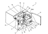
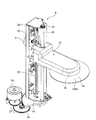
図1は、本発明の実施の形態にかかるメディア処理装置1の外観斜視図である。図2は、図1のメディア処理装置1の内部構造が分かるように、筺体2の上板部分の一部を取り外すとともに、左右の開閉扉11、12を開いた状態を示す斜視図である。図3は、メディア搬送機構8の斜視図である。
(Overall configuration of media processing device)
FIG. 1 is an external perspective view of a media processing apparatus 1 according to an embodiment of the present invention. FIG. 2 is a perspective view showing a state in which a part of the upper plate portion of the housing 2 is removed and the left and right open /
本形態のメディア処理装置1は、CD、DVDまたはBD等の円板状のメディア3に対してデータの書き込みとレーベル印刷とを行って、メディア3を発行するパブリッシャーである。このメディア処理装置1は、その筐体2内に、未使用のブランクメディア等の書き込み可能なメディア3が積層されて収容されるメディア供給用スタッカー(収容部)4と、メディア3へのデータの書き込みおよびメディア3からのデータの読み出しを行うメディアドライブ5と、データが書き込まれたメディア3のレーベル面3aに、書き込みデータの内容を表すタイトル等を含むレーベルを印刷するレーベルプリンター6と、データの書き込みやレーベルの印刷等が行われた排出前のメディア3が積層されて収容されるメディア排出用スタッカー7と、メディア3を搬送するメディア搬送機構8とを有している。
The media processing apparatus 1 of this embodiment is a publisher that issues
筺体2は、略直方体状に形成されている。筐体2の前面には、左右に開閉可能な開閉扉11、12が取り付けられている。開閉扉11の下方には、表示ランプおよび操作ボタン等が配列された操作パネル13が形成されている。操作パネル13の側方には、メディア排出口14が形成されている。
The housing 2 is formed in a substantially rectangular parallelepiped shape. Opening
開閉扉11、12を開けると、図2に示すように、メディア処理装置1の筐体2内の右側の部位に、メディア供給用スタッカー4とメディア排出用スタッカー7とが同軸状態で上下に配置されている。メディア供給用スタッカー4およびメディア排出用スタッカー7の後側の部位には、メディア搬送機構8が配置されている。メディア供給用スタッカー4、メディア排出用スタッカー7およびメディア搬送機構8の側方の部位には、上側にメディアドライブ5が配置され、下側にレーベルプリンター6が配置されている。図2では、メディアドライブ5およびレーベルプリンター6のメディアトレイ5a、6aはそれぞれ手前に引き出されたメディア受け渡し位置にある。メディアドライブ5およびレーベルプリンター6の側方の部位には、レーベルプリンター6へインクを供給するためのインクカートリッジを装着するためのカートリッジ装着部15が設けられている。
When the open /
メディア供給用スタッカー4には、メディア3が、レーベル面3aを上にした状態で厚さ方向に積層されて収容されている。メディア供給用スタッカー4は、前方へ水平に引き出し可能なスライド板4aと、このスライド板4aの上に垂直に配置されている左右一対の円弧状の枠板4b、4cとを備えている。メディア供給用スタッカー4にブランクメディア等の書き込み可能なメディア3を収容あるいは補充する場合には、開閉扉12を開けてスライド板4aを手前に引き出し、メディア3を枠板4b、4cの間に上方から挿入する。枠板4b、4cの間にメディア3が挿入されると、メディア3は、同軸状態で積層されてメディア供給用スタッカー4に収容される。この状態で、スライド板4aを筐体2内へ戻すと、メディア3の収容や補充が完了する。
The media supply stacker 4 accommodates the
メディア排出用スタッカー7は、メディア供給用スタッカー4と同様に、前方に水平に引き出し可能なスライド板7aと、このスライド板7aの上面に垂直に配置されている左右一対の円弧状の枠板7b、7cとを備えている。データ書き込み済みのメディア3やレーベル印刷済みのメディア3はメディア搬送機構8によって円弧状の枠板7b、7cの間に上方から挿入され、同軸状態に積層されてメディア排出用スタッカー7に保管される。開閉扉12を開けてスライド板7aを手前に引き出すことにより、メディア排出用スタッカー7に保管されているメディア3を一括して取り出すことができる。
Similar to the media supply stacker 4, the media discharge stacker 7 includes a
メディア搬送機構8は、メディア3を1枚ずつ筐体2内の各部分に搬送するものであり、メディア3のレーベル面3aの一部分を外周側から中心に延びる帯状に覆った状態で、このメディア3の中心部分を把持する搬送アーム18を備えている。搬送アーム18は、たとえば、メディア供給用スタッカー4に積層されて収容されるメディア3のうちの一番上のメディア3である最上部メディア3Aを順次、把持して取り出し、所定の位置へ搬送する。また、メディア搬送機構8は、シャーシ19と、シャーシ19の上下の水平支持板部分の間に垂直に架け渡されている垂直ガイド軸20とを備えている。搬送アーム18は、垂直ガイド軸20に取り付けられており、垂直ガイド軸20に沿って昇降可能であるとともに、垂直ガイド軸20を中心に左右へ旋回可能となっている。
The
図3に示すように、メディア搬送機構8は、搬送アーム18を昇降させるためのモーター21を備えている。モーター21は、ステッピングモーターである。モーター21の回転は、歯車列22を介してシャーシ19の上端近傍位置に配置されている駆動側プーリー23に伝達される。シャーシ19の下端近傍位置には、従動側プーリー24が配置されており、駆動側プーリー23と従動側プーリー24との間にはタイミングベルト25が架け渡されている。タイミングベルト25の左右のベルト部分の一方には、搬送アーム18の後端部分が固定されている。したがって、モーター21を駆動すると、タイミングベルト25が上下方向に移動し、タイミングベルト25に取り付けられている搬送アーム18が垂直ガイド軸20に沿って昇降する。
As shown in FIG. 3, the
また、メディア搬送機構8は、搬送アーム18を旋回させるためのモーター26を備えており、モーター26の回転は、歯車列27を介して扇形の最終段歯車28に伝達される。扇形の最終段歯車28は、垂直ガイド軸20を中心として左右に旋回可能である。最終段歯車28には、搬送アーム18の昇降機構の構成部品が組み付けられているシャーシ19が搭載されている。モーター26を駆動すると、最終段歯車28が左右に旋回するので、最終段歯車28に搭載されているシャーシ19が最終段歯車28と一体となって垂直ガイド軸20を中心として左右に旋回する。その結果、シャーシ19に搭載されている昇降機構によって保持されている搬送アーム18が垂直ガイド軸20を中心として左右に旋回する。
In addition, the
図2に示すように、メディア供給用スタッカー4およびメディア排出用スタッカー7の一対の枠板4b、4cおよび枠板7b、7cの間には、搬送アーム18が昇降可能な隙間が形成されている。また、上下方向において、メディア供給用スタッカー4とメディア排出用スタッカー7との間には、搬送アーム18が水平に旋回して、メディア排出用スタッカー7の真上まで移動できるように、空間が形成されている。さらに、メディア供給用スタッカー4の上方から搬送アーム18を水平に旋回させると、メディア受け渡し位置にあるメディアドライブ5のメディアトレイ5aに搬送アーム18がアクセス可能となっている。また、上側のメディアトレイ5aをメディアドライブ5に押し込んだ後に搬送アーム18を下降させると、メディア受け渡し位置にあるレーベルプリンター6のメディアトレイ6aに搬送アーム18がアクセス可能となっている。さらに、上下のメディアトレイ5a、6aをメディアドライブ5およびレーベルプリンター6に押し込んだ後に搬送アーム18を下降させると、メディア排出口14に搬送アーム18がアクセス可能となっている。このように、搬送アーム18の昇降および左右への旋回の組み合わせ動作によって、メディア3を各部分に搬送することが可能である。
As shown in FIG. 2, a gap is formed between the pair of
(搬送アームの構成)
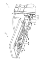
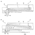
図4は、搬送アーム18を下側から示す斜視図である。図5は、分離機構32を上側から示す斜視図である。図6は、キックレバー39の動作の説明図である。図7は、メディア検出機構34の平面図である。図8は、メディア検出機構34の断面図であり、(A)はメディア3を検出していない状態を示す図、(B)はメディア3を検出している状態を示す図である。図9は、搬送アーム18によって最上部メディア3Aと一緒に直下メディア3Bが持ち上げられたときの状態を示す図である。図10は、メディア搬送機構8の制御部50の、メディア3の搬送制御に関連する構成およびその周辺機器を示すブロック図である。
(Configuration of transfer arm)
FIG. 4 is a perspective view showing the
搬送アーム18には、メディア3の中心孔3bに挿入されるメディアガイド30と、メディア3を把持する把持機構31とが搭載されている。上述のように、搬送アーム18は、メディア供給用スタッカー4に積層されて収容されるメディア3のうちの一番上のメディア3である最上部メディア3Aを順次、把持して取り出し、所定の位置へ搬送する。そのため、搬送アーム18には、最上部メディア3Aに吸着された最上部メディア3Aの直下のメディア3である直下メディア3B(図9参照)を最上部メディア3Aから分離する分離機構32が搭載されている。また、搬送アーム18には、メディア供給用スタッカー4に収容された最上部メディア3Aと搬送アーム18の先端側とが上下方向において所定の距離まで近づいたことを検出するためのメディア検出機構34が搭載されている。把持機構31、分離機構32およびメディア検出機構34の一部は、扁平な略直方体状に形成されるケース体33の中に収容されている。
A media guide 30 that is inserted into the
メディアガイド30は、搬送アーム18の先端側に配置されている。また、メディアガイド30は、搬送アーム18の下面側に配置されている。メディアガイド30の中心部分は、メディア3の調心機能を有するガイド部35となっている。ガイド部35は、下方向に向かうにしたがって外径が小さくなる略円錐台状に形成されている。ガイド部35の外周側には、3個の突起36が同一円上に等角度ピッチで配置されている。3個の突起36の外接円の径は、メディア3の中心孔3bの内径よりもわずかに小さくなっている。把持機構31によってメディア3が把持される際には、ガイド部35によって、メディア3の中心孔3bが3個の突起36の外周側へ案内される。
The media guide 30 is disposed on the front end side of the
把持機構31は、メディア3の中心孔3bの側面に当接してメディア3を把持する円柱状の3個の把持爪(把持部材)38を備えている。3個の把持爪38は、ガイド部35に形成される切欠き部の中に配置されるとともに、同一円上に等角度ピッチで配置されている。3個の把持爪38は、ソレノイド等の駆動源を有する把持爪38の駆動機構に連結されており、連動して径方向へ移動可能となっている。メディア3の中心孔3bが突起36の外周側に配置されている状態で、3個の把持爪38が径方向外側へ移動すると、メディア3の中心孔3bの側面に把持爪38が当接して、メディア3が把持爪38に把持される。また、把持爪38がメディア3を把持している状態で、把持爪38が径方向内側へ移動すると、メディア3が把持爪38から外れる。把持爪38は、メディア3を把持するときに、図9に示すように、直下メディア3Bが吸着された最上部メディア3Aの中心孔3bの側面には当接するが、直下メディア3Bの中心孔3bの側面には当接しないように形成され、配置されている。
The gripping
分離機構32は、中間部39aがケース体33に回動可能に支持されるキックレバー(分離部材)39を備えている。キックレバー39の先端側は、下方に屈曲された後に側方に屈曲された作用片39bとなっている。作用片39bは、ガイド部35に形成される切欠き部の中に配置されている。キックレバー39の基端側には、揺動機構40が設けられている。揺動機構40は、図5に示すように、複合クラッチ歯車41と、鉛直複合伝達歯車42と、水平複合伝達歯車43と、ラック44とを備えている。複合クラッチ歯車41および鉛直複合伝達歯車42は、上下方向を軸方向とする回転が可能となるようにケース体33に支持されている。水平複合伝達歯車43は、水平方向を軸方向とする回転が可能となるようにケース体33に支持されている。ラック44は、シャーシ19に、垂直ガイド軸20と平行に支持されている。
The
ラック44には、水平複合伝達歯車43のピニオン43aが噛み合っている。水平複合伝達歯車43には、ねじ歯車43bが設けられている。ねじ歯車43bは、鉛直複合伝達歯車42のねじ歯車42aに噛み合っている。鉛直複合伝達歯車42には、平歯車42bが設けられている。平歯車42bは、複合クラッチ歯車41の平歯車41aに噛み合っている。複合クラッチ歯車41には、平歯車41aに対して相対回転可能な間欠歯車41bが設けられている。間欠歯車41bは、周面の一部に複数の歯からなる歯列41cを備えている。歯列41cは、鉛直複合伝達歯車42の平歯車42bと噛み合い可能となっている。また、間欠歯車41bの上面には、カム穴41dが形成されている。カム穴41dには、キックレバー39の基端近傍で下方へ突出するカムピン(図示省略)が摺動可能に配置されている。平歯車41aと間欠歯車41bとの間には、クラッチ機構が設けられており、複合クラッチ歯車41の回転範囲内の所定の範囲では、平歯車41aと間欠歯車41bとが供回りし、その他の範囲では、平歯車41aに対して間欠歯車41bが空回りする。
The
メディア供給用スタッカー4に収容された最上部メディア3Aを搬送アーム18が把持して持ち上げる前には、図6(A)に示すように、キックレバー39の作用片39bは、メディア3の中心孔3bの側面よりも径方向内側に配置されている。この状態で、搬送アーム18が上昇を開始すると、複合クラッチ歯車41の平歯車41aとともに間欠歯車41bが回転を開始する。間欠歯車41bが平歯車41aと一緒に回転すると、キックレバー39が中間部39aを中心に回動して、作用片39bが矢印Vの方向へ移動する。搬送アーム18が所定量上昇して、間欠歯車41bが所定量回転すると、図6(B)に示すように、作用片39bの先端部分が、把持爪38によって把持されているメディア3の中心孔3bの側面よりも径方向外側に移動する。また、この状態で、搬送アーム18が下降すると、平歯車41aとともに間欠歯車41bが回転する。搬送アーム18が所定量下降して、間欠歯車41bが所定量回転すると、キックレバー39が中間部39aを中心に回動して、図6(A)に示すように、作用片39bの先端部分がメディア3の中心孔3bの側面よりも径方向内側に移動する。
Before the
このように、搬送アーム18の昇降に連動して、キックレバー39が中間部39aを中心に回動し、キックレバー39の作用片39bがメディア3の径方向へ移動する。なお、搬送アーム18が上昇する際には、作用片39bの先端部分がメディア3の径方向外側に向かって所定量移動すると、その後、平歯車41aに対して間欠歯車41bが空回りして、キックレバー39への動力の伝達が遮断される。また、搬送アーム18が下降する際には、作用片39bの先端部分がメディア3の径方向内側に向かって所定量移動すると、その後、平歯車41aに対して間欠歯車41bが空回りして、キックレバー39への動力の伝達が遮断される。
Thus, in conjunction with the raising and lowering of the
作用片39bは、図9に示すように、最上部メディア3Aの中心孔3bの側面には当接しないが、最上部メディア3Aに吸着された直下メディア3Bの中心孔3bの側面に当接する位置に配置されている。そのため、把持爪38が把持する最上部メディア3Aに直下メディア3Bが吸着された状態で、搬送アーム18が上昇し、作用片39bがV方向へ移動すると、図6(B)に示すように、作用片39bが直下メディア3Bの中心孔3bの側面に当接して、最上部メディア3Aに対して直下メディア3Bを矢印Vの方向へ移動させる。直下メディア3Bが矢印Vの方向へ移動すると、最上部メディア3Aに吸着された直下メディア3Bは、最上部メディア3Aから分離して、落下する。
As shown in FIG. 9, the
メディア検出機構34は、図7、図8に示すように、検出器(メディア検出器)46と、検出レバー47とを備えている。検出器46は、たとえば、所定の隙間を介して対向配置される発光素子と受光素子とを備える光学式のセンサである。検出レバー47の基端側は、水平方向を軸方向とする回動が可能となるようにケース体33に支持されている。検出レバー47の先端部47aは、下方に屈曲しており、図4に示すように、ケース体33の底面に形成される開口部33aからケース体33の下面側へ突出している。検出レバー47の側面には、図7に示すように、検出器46の発光素子と受光素子との間を遮る遮光部47bが形成されている。
The
メディア検出機構34では、搬送アーム18の下側の所定の範囲内にメディア3がないときには、図8(A)に示すように、検出レバー47の先端部47aがケース体33の下面側へ大きく突出している。また、このときには、検出器46の発光素子と受光素子との間を遮光部47bが遮っている。一方、搬送アーム18が下降して、メディア供給用スタッカー4に収容される最上部メディア3Aに検出レバー47の先端部47aの先端が当接すると、図8(B)に示すように、検出レバー47がその基端側を中心に回動して、検出器46の発光素子と受光素子との間から遮光部47bが外れる。このように、検出器46の発光素子と受光素子との間から遮光部47bが外れることで、メディア供給用スタッカー4に収容された最上部メディア3Aと搬送アーム18の先端側とが上下方向において所定の距離まで近づいたことが検出される。また、搬送アーム18に最上部メディア3Aが把持されている間は、検出器46の発光素子と受光素子との間から遮光部47bが外れているため、メディア検出機構34によって、搬送アーム18に最上部メディア3Aが把持されていることも検出される。
In the
なお、図10に示すように、メディア搬送機構8の制御部50は、モーター21を制御するモーター制御部51を備えており、検出器46は、モーター制御部51に接続されている。
As shown in FIG. 10, the
(メディア搬送機構の制御)
図11は、メディア3の積層状態を説明するための説明図である。上述のように、搬送アーム18には、分離機構32が搭載されているため、搬送アーム18に把持されて持ち上げられる最上部メディア3Aに吸着された直下メディア3Bを最上部メディア3Aから分離して落下させることが可能である。ここで、メディア3がCDやDVD(第1のメディア)である場合には、図11(A)に示すように、メディア3のレーベル面3aの反対側となる記録面側の中心孔3bの周りに、記録面を保護するための円環状の突起であるスタックリング3cが形成されている。一方、メディア3がBD(第2のメディア)である場合には、図11(B)に示すように、メディア3の記録面側にスタックリングが形成されておらず、メディア3の記録面側は平面状になっている。あるいは、メディア3がBDである場合には、メディア3の記録面側に、スタックリング3cよりも低いスタックリングが形成されている。そのため、メディア供給用スタッカー4にメディア3としてBDが積層されて収容されている場合、BDとその直下のメディア3との間に生じる吸着力が大きくなる。
(Control of media transport mechanism)
FIG. 11 is an explanatory diagram for explaining the stacked state of the
本形態のメディア搬送機構8では、メディア3間の吸着力が大きい場合であっても、最上部メディア3Aに直下メディア3Bが吸着されて、最上部メディア3Aと一緒に直下メディア3Bが搬送アーム18で持ち上げられたときに、最上部メディア3Aから直下メディア3Bを分離することができるように、モーター制御部51が、モーター21の回転速度を制御して、搬送アーム18の上昇速度とキックレバー39の作用片39bの移動速度とを制御する。具体的には、以下のように、モーター制御部51が搬送アーム18の上昇速度とキックレバー39の作用片39bの移動速度とを制御する。
In the
まず、最上部メディア3AがBDであって、最上部メディア3Aに直下メディア3Bが吸着されて、最上部メディア3Aと一緒に直下メディア3Bが搬送アーム18で持ち上げられたとしても、最上部メディア3Aと直下メディア3Bとが一緒に持ち上げられてからの時間の経過に伴って、直下メディア3Bに作用する自重の影響で、最上部メディア3Aと直下メディア3Bとの間に空気が入り込みやすくなり、最上部メディア3Aと直下メディア3Bとの吸着力が低下していく。そこで、本形態では、特定条件下において、モーター21の回転速度を下げ、搬送アーム18の上昇速度と作用片39bの移動速度とを遅くして、最上部メディア3Aを把持した搬送アーム18の上昇開始からキックレバー39による直下メディア3Bの分離動作が行われるまでの時間を長くすることで、分離動作が行われる際の最上部メディア3Aと直下メディア3Bとの吸着力を低下させて、最上部メディア3Aから直下メディア3Bを分離している。
First, even if the
具体的には、モーター21の回転速度は、2段階に切替可能となっており、モーター制御部51は、特定条件以外の条件下でモーター21が通常の回転速度で回転し、かつ、特定条件下でモーター21が通常の回転速度よりも遅い回転速度で回転するように、モーター21の回転速度を切り替えて、搬送アーム18の上昇速度および作用片39bの移動速度を切り替える。すなわち、特定条件以外の条件下での搬送アーム18の上昇速度を第1の速度とし、特定条件以外の条件下での作用片39bの移動速度を第3の速度とすると、モーター制御部51は、特定条件下で、モーター21の回転速度を切り替えて、搬送アーム18の上昇速度を第1の速度から第1の速度よりも遅い第2の速度に切り替えるとともに、作用片39bの移動速度を第3の速度から第3の速度よりも遅い第4の速度に切り替える。
Specifically, the rotation speed of the
特定条件は、たとえば、メディア供給用スタッカー4に収容される全てのメディア3がBDであって、かつ、メディア供給用スタッカー4に収容されるメディア3の枚数が2枚となっている場合である。メディア供給用スタッカー4に収容される全てのメディア3がBDであって、かつ、メディア供給用スタッカー4に収容されるメディア3の枚数が3枚以上である場合、メディア3間に吸着力が生じると、搬送アーム18で最上部メディア3Aを持ち上げる際には、メディア供給用スタッカー4に収容される最上部メディア3Aと直下メディア3Bとの間に直下メディア3Bよりも下の3枚目以降のメディア3の重量が作用するため、搬送アーム18で最上部メディア3Aを持ち上げる際に最上部メディア3Aから直下メディア3Bが分離しやすい。これに対して、メディア供給用スタッカー4に収容されるメディア3の枚数が2枚である場合、搬送アーム18で最上部メディア3Aを持ち上げる際に、この2枚のメディア3である最上部メディア3Aと直下メディア3Bとの間に作用するのは直下メディア3Bの自重のみであるため、最上部メディア3Aと一緒に直下メディア3Bが搬送アーム18によって持ち上げられやすくなり、また、2枚のメディア3が搬送アーム18によって持ち上げられると、最上部メディア3Aから直下メディア3Bが分離しにくい。したがって、最上部メディア3Aから直下メディア3Bを分離しやすくするため、この条件下において、モーター制御部51は、モーター21の回転速度を切り替えて、搬送アーム18の上昇速度および作用片39bの移動速度を遅くする。
The specific condition is, for example, a case where all the
なお、メディア供給用スタッカー4に収容されるメディア3の枚数が2枚となっているか否かは、検出器46での検出結果と、ステッピングモーターであるモーター21のステップ数とに基づいて、たとえば、モーター制御部51が検出する。すなわち、検出器46の発光素子と受光素子との間から検出レバー47の遮光部47bが外れたときの、モーター21の、所定の基準位置からステップ数に基づいて、メディア供給用スタッカー4に収容されるメディア3の枚数が2枚となっているか否かが検出される。また、メディア供給用スタッカー4に収容されるメディア3の枚数が2枚となっていることが検出されると、モーター制御部51は、モーター21の回転速度を自動で切り替える。
Whether or not the number of
また、特定条件は、たとえば、メディア供給用スタッカー4に収容されるメディア3の中にCDやDVDとBDとが混在している場合であって、かつ、図11(C)に示すように、メディア供給用スタッカー4に収容される最上部メディア3AがBDとなっており、また、直下メディア3BがCDまたはDVDとなっている場合である。メディア供給用スタッカー4に収容されるメディアの枚数が3枚以上であっても、この場合には、上から2枚目の直下メディア3Bとその下(上から3枚目)のメディア3との間の隙間が大きくなるため、直下メディア3Bとその下のメディア3との間の吸着力が弱くなり、搬送アーム18で最上部メディア3Aを持ち上げる際に、この2枚のメディア3は分離しやすくなる。一方で、最上部メディア3Aと直下メディア3Bとは密着して、その間に生じる吸着力が大きくなる。そのため、この場合には、メディア供給用スタッカー4に収容されるメディアの枚数が3枚以上であっても、搬送アーム18で最上部メディア3Aを持ち上げる際に、最上部メディア3Aと一緒に直下メディア3Bが搬送アーム18で持ち上げられやすくなり、また、2枚のメディア3が搬送アーム18によって持ち上げられると、最上部メディア3Aから直下メディア3Bが分離しにくい。したがって、最上部メディア3Aから直下メディア3Bを分離しやすくするため、この条件下において、モーター制御部51は、モーター21の回転速度を切り替えて、搬送アーム18の上昇速度および作用片39bの移動速度を遅くする。
Further, the specific condition is, for example, a case where CD, DVD, and BD are mixed in the
なお、メディア供給用スタッカー4に収容される最上部メディア3AがBDとなっており、かつ、直下メディア3BがCDまたはDVDとなっているか否かは、たとえば、メディア処理装置1のオペレーターによって確認される。また、オペレーターによって入力された情報に基づいて、モーター制御部51は、モーター21の回転速度を切り替える。
Whether the
(本実施の形態の主な効果)
以上説明したように、本形態では、最上部メディア3Aから直下メディア3Bが分離しにくい特定条件下において、モーター制御部51は、モーター21の回転速度を下げ、搬送アーム18の上昇速度と作用片39bの移動速度とを遅くして、最上部メディア3Aを把持した搬送アーム18の上昇開始からキックレバー39による直下メディア3Bの分離動作が行われるまでの時間を長くしている。そのため、最上部メディア3Aと一緒に直下メディア3Bが搬送アーム18で持ち上げられた場合であっても、キックレバー39による分離動作が行われる際の最上部メディア3Aと直下メディア3Bとの吸着力を低下させることができる。
(Main effects of this embodiment)
As described above, in this embodiment, the
したがって、キックレバー39による分離動作が行われる前に、最上部メディア3Aに吸着された直下メディア3Bを落下させることが可能になり、また、キックレバー39による分離動作が行われる前に最上部メディア3Aに吸着された直下メディア3Bを落下させることができなくても、キックレバー39による分離動作によって、最上部メディア3Aに吸着された直下メディア3Bを最上部メディア3Aから分離して落下させることが可能になる。その結果、最上部メディア3Aにスタックリングが形成されていなくて、あるいは、最上部メディア3Aに形成されるスタックリングの高さが低くて、積層されたメディア3間に生じる吸着力が大きい場合であっても、最上部メディア3Aと一緒に直下メディア3Bが搬送アーム18で持ち上げられたときに、把持爪38によって最上部メディア3Aを把持しつつ、最上部メディア3Aから直下メディア3Bを分離することが可能になる。そのため、本形態では、積層されたメディア3間に生じる吸着力が大きい場合であっても、メディア3を1枚のみ確実に搬送することが可能になる。
Therefore, it is possible to drop the
(他の実施の形態)
上述した形態では、モーター21の回転速度が切り替えられる特定条件は、メディア供給用スタッカー4に収容されるメディア3の枚数が2枚となっている場合や、メディア供給用スタッカー4に収容される最上部メディア3AがBDとなっており、かつ、直下メディア3BがCDまたはDVDとなっている場合であるが、モーター21の回転速度が切り替えられる特定条件は、たとえば、搬送アーム18によって持ち上げられるメディア3の重さが2枚以上のメディア3の重さとなっている場合であっても良い。この場合には、搬送アーム18によって、最上部メディア3Aと一緒に直下メディア3Bが持ち上げられているが、搬送アーム18の上昇速度およびキックレバー39の作用片39bの移動速度を遅くして、最上部メディア3Aから直下メディア3Bを分離することが可能になる。
(Other embodiments)
In the embodiment described above, the specific condition for switching the rotation speed of the
なお、この場合には、搬送アーム18によって持ち上げられるメディア3の重さが2枚以上のメディア3の重さとなっているか否かは、モーター21の電流値に基づいて、たとえば、モーター制御部51が検出する。また、搬送アーム18によって持ち上げられるメディア3の重さが2枚以上のメディア3の重さとなっていることが検出されると、モーター制御部51は、モーター21の回転数を自動で切り替える。
In this case, whether or not the weight of the
また、モーター21の回転速度が切り替えられる特定条件は、たとえば、メディア処理装置1が夜間に運転されている場合であっても良いし、メディア処理装置1が無人で運転されている場合であっても良い。メディア処理装置1が夜間に運転される場合には、メディア処理装置1のオペレーターがメディア搬送機構8の近くにいない可能性が高い。また、メディア処理装置1が無人で運転される場合には、オペレーターはメディア搬送機構8の近くにいない。そのため、これらの場合には、最上部メディア3Aと直下メディア3Bとの間の吸着力が大きくて、最上部メディア3Aから直下メディア3Bを分離できずに最上部メディア3Aが直下メディア3Bと一緒に搬送アーム18から落下すると、メディア搬送機構8の運転がそのまま停止してしまったり、メディア搬送機構8を損傷させたりするおそれがあるが、メディア処理装置1が夜間に運転されている場合や無人で運転されている場合を特定条件として、この条件下で、モーター21の回転速度を切り替えれば、最上部メディア3Aと直下メディア3Bとの間の吸着力が大きい場合であっても、最上部メディア3Aと一緒に直下メディア3Bが搬送アーム18で持ち上げられたときに、最上部メディア3Aから直下メディア3Bを分離することが可能になり、その結果、これらの不具合を解消することが可能になる。なお、メディア処理装置1の夜間運転時や無人運転時には、オペレーターの入力操作に基づいて、モーター制御部51は、モーター21の回転速度を切り替える。
The specific condition for switching the rotation speed of the
上述した形態では、モーター21が回転すると、搬送アーム18が昇降するとともに、作用片39bが移動するが、搬送アーム18を上昇させる駆動源と、作用片39bを移動させる駆動源とが別個に設けられても良い。この場合には、特定条件下で、搬送アーム18の上昇速度を変えずに、作用片39bの移動速度を遅くしても良い。また、この場合には、搬送アーム18が所定の高さまで上昇したときにキックレバー39による分離動作が行われるように構成されているのであれば、特定条件下で、作用片39bの移動速度を変えずに、搬送アーム18の上昇速度を遅くしても良い。また、この場合には、特定条件下で、搬送アーム18の上昇速度を遅くするとともに、作用片39bの移動速度を遅くしても良い。このようにしても、最上部メディア3Aを把持した搬送アーム18の上昇開始からキックレバー39による直下メディア3Bの分離動作が行われるまでの時間を長くすることが可能になる。
In the above-described form, when the
1・・・メディア処理装置、3・・・メディア、3A・・・最上部メディア、3B・・・直下メディア、3b・・・中心孔、3c・・・スタックリング(第1のスタックリング)、4・・・メディア供給用スタッカー(収容部)、8・・・メディア搬送機構、18・・・搬送アーム、21・・・モーター(ステッピングモーター)、38・・・把持爪(把持部材)、39・・・キックレバー(分離部材)、46・・・検出器(メディア検出器)、50・・・制御部 DESCRIPTION OF SYMBOLS 1 ... Media processing apparatus, 3 ... Media, 3A ... Uppermost media, 3B ... Directly below media, 3b ... Center hole, 3c ... Stack ring (1st stack ring), 4... Media supply stacker (accommodating portion), 8... Media transport mechanism, 18... Transport arm, 21... Motor (stepping motor), 38. ... Kick lever (separating member), 46 ... Detector (media detector), 50 ... Control unit
Claims (7)
前記収容部に収容された前記メディアを把持する把持部材、及び前記メディアの内孔か
ら前記メディアの径方向に移動する分離部材を有し、鉛直方向に移動する搬送アームと、
前記把持部材で前記メディアを把持して前記搬送アームを鉛直方向の上方へ移動させる
ときの前記搬送アームの上昇速度を第1の速度、もしくは第1の速度よりも遅い第2の速
度で移動させる搬送アーム駆動部材と、
前記搬送アーム駆動部材で前記搬送アームを移動させるときの上昇速度を切り替える制
御部と、
前記収容部に収容される前記メディアの枚数を検知するメディア検知部を有し、
前記制御部は、前記メディア検知部で検知された前記メディアの枚数が2枚のとき、前
記搬送アームの上昇速度を前記第1の速度から前記第2の速度に切り替えることを特徴とするメディア搬送機構。 An accommodating portion for laminating and accommodating disk-shaped media having inner holes;
A holding member that holds the medium accommodated in the accommodating portion, and a separation member that moves in a radial direction of the medium from an inner hole of the medium, and a transfer arm that moves in a vertical direction;
When the medium is gripped by the gripping member and the transport arm is moved upward in the vertical direction, the ascending speed of the transport arm is moved at the first speed or a second speed that is slower than the first speed. A transfer arm driving member;
A control for switching the ascending speed when the transfer arm is moved by the transfer arm driving member.
Mibe and
A media detection unit that detects the number of media stored in the storage unit;
When the number of the media detected by the media detection unit is two, the control unit
A media transport mechanism that switches the ascending speed of the transport arm from the first speed to the second speed.
くは前記第3の速度よりも遅い第4の速度で移動させる分離部材駆動部材を有する請求項
1に記載のメディア搬送機構。 2. The separation member drive member according to claim 1, wherein the separation member driving member moves the movement speed when moving the separation member in the radial direction of the medium at a third speed or a fourth speed that is slower than the third speed. Media transport mechanism.
前記搬送アーム駆動部材が前記搬送アームを前記第1の速度で移動させるとき、前記分
離部材駆動部材は、前記分離部材を前記第3の速度で移動させる請求項2に記載のメディ
ア搬送機構。 The transfer arm driving member and the separating member driving member are interlocked,
The media transport mechanism according to claim 2, wherein when the transport arm driving member moves the transport arm at the first speed, the separation member driving member moves the separation member at the third speed.
た収容部へ下降させ、
前記収容部に収容された前記メディアの枚数を検出し、
検出された前記収容部に収容された前記メディアの枚数が3枚以上のときには前記搬送
アームの前記把持部材で前記メディアを把持した後、第1の速度で前記搬送アームを鉛直
方向の上方に移動させ、
検出された前記収容部に収容された前記メディアの枚数が2枚のときには前記搬送アー
ムの前記把持部材で把持した後、前記第1の速度よりも遅い第2の速度で前記搬送アーム
を鉛直方向の上方に移動させることを特徴とするメディア搬送機構の制御方法。 Lowering the transport arm having the gripping member to the storage portion in which the disk-shaped media having the inner holes are stacked and stored,
Detecting the number of media stored in the storage unit;
When the detected number of media accommodated in the accommodating portion is three or more, the media is gripped by the gripping member of the transport arm, and then the transport arm is moved upward in the vertical direction at a first speed. Let
When the detected number of media stored in the storage unit is two, the medium is gripped by the gripping member of the transport arm, and then the transport arm is moved in the vertical direction at a second speed that is slower than the first speed. A method for controlling a media transport mechanism, wherein the media transport mechanism is moved upward.
送アームを前記第1の速度で移動させた後、前記搬送アームに配設された分離部材を第3
の速度で前記メディアの径方向に移動させ、
検出された前記収容部に収容された前記メディアの枚数が2枚のときには前記搬送アー
ムを前記第2の速度で移動させた後、前記分離部材を前記第3の速度よりも遅い第4の速
度で移動させる請求項4に記載のメディア搬送機構の制御方法。 When the detected number of the media stored in the storage unit is three or more, the transport arm is moved at the first speed, and then the separation member disposed on the transport arm is moved to the third position.
Moved in the radial direction of the medium at a speed of
When the detected number of the media stored in the storage unit is 2, the transfer arm is moved at the second speed, and then the separation member is moved at a fourth speed lower than the third speed. The method for controlling a media transport mechanism according to claim 4, wherein
前記収容部に収容された前記メディアを把持する把持部材、及び前記メディアの内孔か
ら前記メディアの径方向に移動する分離部材を有して鉛直方向に移動するとともに軸を中
心に回転する搬送アームと、
前記把持部材で前記メディアを把持して前記搬送アームを鉛直方向の上方へ移動させる
ときの前記搬送アームの上昇速度を第1の速度、もしくは第1の速度よりも遅い第2の速
度で移動させる搬送アーム駆動部材と、
前記搬送アームで搬送された前記メディアにデータを記録する記録部と、
前記搬送アーム駆動部材で前記搬送アームを移動させるときの上昇速度を切り替える制
御部と、
前記収容部に収容される前記メディアの枚数を検知するメディア検知部を有し、
前記制御部は、前記メディア検知部で検知された前記メディアの枚数が2枚のとき、前
記搬送アームの上昇速度を前記第1の速度から前記第2の速度に切り替えることを特徴とするメディア処理装置。 An accommodating portion for laminating and accommodating disk-shaped media having inner holes;
A conveyance arm that has a gripping member that grips the medium housed in the housing portion and a separation member that moves in the radial direction of the medium from an inner hole of the medium and moves in the vertical direction and rotates about an axis When,
When the medium is gripped by the gripping member and the transport arm is moved upward in the vertical direction, the ascending speed of the transport arm is moved at the first speed or a second speed that is slower than the first speed. A transfer arm driving member;
A recording unit for recording data on the medium transported by the transport arm;
A control for switching the ascending speed when the transfer arm is moved by the transfer arm driving member.
Mibe and
A media detection unit that detects the number of media stored in the storage unit;
When the number of the media detected by the media detection unit is two, the control unit
A media processing apparatus, wherein the ascending speed of the transfer arm is switched from the first speed to the second speed.
くは前記第3の速度よりも遅い第4の速度で移動させる分離部材駆動部材を有する請求項
6に記載のメディア処理装置。
Claim having a third velocity, or separating member drive member that moves at the slower than the third speed fourth speed movement speed when moving the separating member in a radial direction of the medium
6. The media processing device according to 6.
Priority Applications (4)
| Application Number | Priority Date | Filing Date | Title |
|---|---|---|---|
| JP2011225607A JP5874294B2 (en) | 2011-10-13 | 2011-10-13 | Media transport mechanism, control method of media transport mechanism, and media processing apparatus |
| CN201210369670.1A CN103050137B (en) | 2011-10-13 | 2012-09-27 | The control method of media carrying mechanism, media carrying mechanism and media processor |
| EP12187731.0A EP2581907A2 (en) | 2011-10-13 | 2012-10-09 | Media transportation mechanism, method of controlling a media transportation mechanism, and media processing device |
| US13/650,423 US8695025B2 (en) | 2011-10-13 | 2012-10-12 | Media transportation mechanism, method of controlling a media transportation mechanism, and media processing device |
Applications Claiming Priority (1)
| Application Number | Priority Date | Filing Date | Title |
|---|---|---|---|
| JP2011225607A JP5874294B2 (en) | 2011-10-13 | 2011-10-13 | Media transport mechanism, control method of media transport mechanism, and media processing apparatus |
Publications (3)
| Publication Number | Publication Date |
|---|---|
| JP2013089259A JP2013089259A (en) | 2013-05-13 |
| JP2013089259A5 JP2013089259A5 (en) | 2014-11-06 |
| JP5874294B2 true JP5874294B2 (en) | 2016-03-02 |
Family
ID=47358338
Family Applications (1)
| Application Number | Title | Priority Date | Filing Date |
|---|---|---|---|
| JP2011225607A Expired - Fee Related JP5874294B2 (en) | 2011-10-13 | 2011-10-13 | Media transport mechanism, control method of media transport mechanism, and media processing apparatus |
Country Status (4)
| Country | Link |
|---|---|
| US (1) | US8695025B2 (en) |
| EP (1) | EP2581907A2 (en) |
| JP (1) | JP5874294B2 (en) |
| CN (1) | CN103050137B (en) |
Families Citing this family (5)
| Publication number | Priority date | Publication date | Assignee | Title |
|---|---|---|---|---|
| JP4375425B2 (en) * | 2007-04-05 | 2009-12-02 | セイコーエプソン株式会社 | Media transport mechanism, media processing apparatus including the same, and media transport method |
| CN109285566A (en) * | 2017-07-20 | 2019-01-29 | 光宝科技股份有限公司 | Disk fetching device and its operating method |
| CN111717672A (en) * | 2019-03-22 | 2020-09-29 | 光宝电子(广州)有限公司 | Slicing device |
| CN112270939A (en) * | 2020-10-29 | 2021-01-26 | 义乌贰亿电子商务有限公司 | Automatic CD replacing device for desk computer |
| CN116994613B (en) * | 2023-07-31 | 2024-02-13 | 平东凡星(东莞)云科技有限公司 | Device for reading record and migration of optical storage medium |
Family Cites Families (12)
| Publication number | Priority date | Publication date | Assignee | Title |
|---|---|---|---|---|
| JP3852367B2 (en) * | 2002-05-14 | 2006-11-29 | ティアック株式会社 | Disk unit |
| JP4839621B2 (en) * | 2005-01-19 | 2011-12-21 | ティアック株式会社 | Disk processing unit |
| JP2007310920A (en) * | 2006-05-16 | 2007-11-29 | Seiko Epson Corp | Gripping mechanism of disk |
| JP4835363B2 (en) * | 2006-10-04 | 2011-12-14 | セイコーエプソン株式会社 | Media processing apparatus and method for controlling media processing apparatus |
| JP5056127B2 (en) * | 2007-04-05 | 2012-10-24 | セイコーエプソン株式会社 | Media transport mechanism and media processing apparatus provided with the same |
| JP4375425B2 (en) | 2007-04-05 | 2009-12-02 | セイコーエプソン株式会社 | Media transport mechanism, media processing apparatus including the same, and media transport method |
| JP4882864B2 (en) * | 2007-05-18 | 2012-02-22 | セイコーエプソン株式会社 | Media transport mechanism and media processing apparatus provided with the same |
| JP4877091B2 (en) * | 2007-06-19 | 2012-02-15 | セイコーエプソン株式会社 | Control method of media transport mechanism and media processing apparatus |
| JP4918888B2 (en) * | 2007-06-19 | 2012-04-18 | セイコーエプソン株式会社 | Media processing apparatus and control method thereof |
| JP5205890B2 (en) * | 2007-09-18 | 2013-06-05 | セイコーエプソン株式会社 | Media processing apparatus and method for controlling media processing apparatus |
| JP5176815B2 (en) * | 2008-09-24 | 2013-04-03 | セイコーエプソン株式会社 | Media processing apparatus, method for controlling media processing apparatus, and control program therefor |
| JP5146233B2 (en) | 2008-09-30 | 2013-02-20 | セイコーエプソン株式会社 | Media transport mechanism and media processing apparatus provided with the same |
-
2011
- 2011-10-13 JP JP2011225607A patent/JP5874294B2/en not_active Expired - Fee Related
-
2012
- 2012-09-27 CN CN201210369670.1A patent/CN103050137B/en not_active Expired - Fee Related
- 2012-10-09 EP EP12187731.0A patent/EP2581907A2/en not_active Withdrawn
- 2012-10-12 US US13/650,423 patent/US8695025B2/en active Active
Also Published As
| Publication number | Publication date |
|---|---|
| CN103050137B (en) | 2016-03-09 |
| JP2013089259A (en) | 2013-05-13 |
| CN103050137A (en) | 2013-04-17 |
| US8695025B2 (en) | 2014-04-08 |
| EP2581907A2 (en) | 2013-04-17 |
| US20130094336A1 (en) | 2013-04-18 |
Similar Documents
| Publication | Publication Date | Title |
|---|---|---|
| JP5874294B2 (en) | Media transport mechanism, control method of media transport mechanism, and media processing apparatus | |
| JP4839621B2 (en) | Disk processing unit | |
| JP5927537B2 (en) | Disk unit | |
| US8132506B2 (en) | Media processing device and control method for a media processing device | |
| JP5176815B2 (en) | Media processing apparatus, method for controlling media processing apparatus, and control program therefor | |
| US7448051B2 (en) | Printer tray picker | |
| US8413179B2 (en) | Disk holding device and disk processor for a disk having a center hole | |
| JP5205890B2 (en) | Media processing apparatus and method for controlling media processing apparatus | |
| JP2007314330A (en) | Tray separation unit, tray separation device with tray separation unit and tray separation method | |
| US8352974B2 (en) | Disk holding device and disk processor for a disk having a center hole | |
| JP5182510B2 (en) | Disc sorter and disc processing apparatus | |
| JP2013008417A (en) | Medium conveyance mechanism and medium processor | |
| JP5187516B2 (en) | Disk storage amount detection apparatus and disk processing apparatus | |
| US20090193446A1 (en) | Apparatuses for Transportation of Disc in Connection with Recording Data and Apparatus for Such Recording | |
| JP2721800B2 (en) | Disc changer | |
| JP5196165B2 (en) | Disc sorter and disc processing apparatus | |
| JP2014002805A (en) | Disc device | |
| JP3441290B2 (en) | Disk autochanger device | |
| JP2538656Y2 (en) | Disk mis-insertion prevention device | |
| JP2014002831A (en) | Disk holding device and disk processing device | |
| JP5500228B2 (en) | Media processing apparatus and method for controlling media processing apparatus | |
| JP2007035223A (en) | Disk device | |
| JP2006114153A (en) | Disk drive unit and disk cartridge | |
| JP2011123933A (en) | Disk chucking mechanism and disk drive device | |
| JPH10255374A (en) | Discoid recording medium housing device |
Legal Events
| Date | Code | Title | Description |
|---|---|---|---|
| A521 | Request for written amendment filed |
Free format text: JAPANESE INTERMEDIATE CODE: A523 Effective date: 20140918 |
|
| A621 | Written request for application examination |
Free format text: JAPANESE INTERMEDIATE CODE: A621 Effective date: 20140918 |
|
| RD04 | Notification of resignation of power of attorney |
Free format text: JAPANESE INTERMEDIATE CODE: A7424 Effective date: 20150107 |
|
| A977 | Report on retrieval |
Free format text: JAPANESE INTERMEDIATE CODE: A971007 Effective date: 20150702 |
|
| A131 | Notification of reasons for refusal |
Free format text: JAPANESE INTERMEDIATE CODE: A131 Effective date: 20150825 |
|
| A521 | Request for written amendment filed |
Free format text: JAPANESE INTERMEDIATE CODE: A523 Effective date: 20151021 |
|
| TRDD | Decision of grant or rejection written | ||
| A01 | Written decision to grant a patent or to grant a registration (utility model) |
Free format text: JAPANESE INTERMEDIATE CODE: A01 Effective date: 20151222 |
|
| A61 | First payment of annual fees (during grant procedure) |
Free format text: JAPANESE INTERMEDIATE CODE: A61 Effective date: 20160104 |
|
| R150 | Certificate of patent or registration of utility model |
Ref document number: 5874294 Country of ref document: JP Free format text: JAPANESE INTERMEDIATE CODE: R150 |
|
| S531 | Written request for registration of change of domicile |
Free format text: JAPANESE INTERMEDIATE CODE: R313531 |
|
| R350 | Written notification of registration of transfer |
Free format text: JAPANESE INTERMEDIATE CODE: R350 |
|
| LAPS | Cancellation because of no payment of annual fees |