KR20080003437A - Masking article and method of masking a substrate to be coated - Google Patents
Masking article and method of masking a substrate to be coated Download PDFInfo
- Publication number
- KR20080003437A KR20080003437A KR1020077027056A KR20077027056A KR20080003437A KR 20080003437 A KR20080003437 A KR 20080003437A KR 1020077027056 A KR1020077027056 A KR 1020077027056A KR 20077027056 A KR20077027056 A KR 20077027056A KR 20080003437 A KR20080003437 A KR 20080003437A
- Authority
- KR
- South Korea
- Prior art keywords
- masking
- body portion
- adhesive
- masking article
- article
- Prior art date
Links
Images


Classifications
-
- B—PERFORMING OPERATIONS; TRANSPORTING
- B05—SPRAYING OR ATOMISING IN GENERAL; APPLYING FLUENT MATERIALS TO SURFACES, IN GENERAL
- B05B—SPRAYING APPARATUS; ATOMISING APPARATUS; NOZZLES
- B05B12/00—Arrangements for controlling delivery; Arrangements for controlling the spray area
- B05B12/16—Arrangements for controlling delivery; Arrangements for controlling the spray area for controlling the spray area
- B05B12/20—Masking elements, i.e. elements defining uncoated areas on an object to be coated
- B05B12/26—Masking elements, i.e. elements defining uncoated areas on an object to be coated for masking cavities
- B05B12/265—Masking elements, i.e. elements defining uncoated areas on an object to be coated for masking cavities between a door and a post, e.g. foam strips
-
- B—PERFORMING OPERATIONS; TRANSPORTING
- B05—SPRAYING OR ATOMISING IN GENERAL; APPLYING FLUENT MATERIALS TO SURFACES, IN GENERAL
- B05B—SPRAYING APPARATUS; ATOMISING APPARATUS; NOZZLES
- B05B12/00—Arrangements for controlling delivery; Arrangements for controlling the spray area
- B05B12/16—Arrangements for controlling delivery; Arrangements for controlling the spray area for controlling the spray area
- B05B12/20—Masking elements, i.e. elements defining uncoated areas on an object to be coated
- B05B12/24—Masking elements, i.e. elements defining uncoated areas on an object to be coated made at least partly of flexible material, e.g. sheets of paper or fabric
-
- B—PERFORMING OPERATIONS; TRANSPORTING
- B05—SPRAYING OR ATOMISING IN GENERAL; APPLYING FLUENT MATERIALS TO SURFACES, IN GENERAL
- B05D—PROCESSES FOR APPLYING FLUENT MATERIALS TO SURFACES, IN GENERAL
- B05D1/00—Processes for applying liquids or other fluent materials
- B05D1/32—Processes for applying liquids or other fluent materials using means for protecting parts of a surface not to be coated, e.g. using stencils, resists
-
- C—CHEMISTRY; METALLURGY
- C09—DYES; PAINTS; POLISHES; NATURAL RESINS; ADHESIVES; COMPOSITIONS NOT OTHERWISE PROVIDED FOR; APPLICATIONS OF MATERIALS NOT OTHERWISE PROVIDED FOR
- C09J—ADHESIVES; NON-MECHANICAL ASPECTS OF ADHESIVE PROCESSES IN GENERAL; ADHESIVE PROCESSES NOT PROVIDED FOR ELSEWHERE; USE OF MATERIALS AS ADHESIVES
- C09J7/00—Adhesives in the form of films or foils
- C09J7/20—Adhesives in the form of films or foils characterised by their carriers
- C09J7/28—Metal sheet
-
- Y—GENERAL TAGGING OF NEW TECHNOLOGICAL DEVELOPMENTS; GENERAL TAGGING OF CROSS-SECTIONAL TECHNOLOGIES SPANNING OVER SEVERAL SECTIONS OF THE IPC; TECHNICAL SUBJECTS COVERED BY FORMER USPC CROSS-REFERENCE ART COLLECTIONS [XRACs] AND DIGESTS
- Y10—TECHNICAL SUBJECTS COVERED BY FORMER USPC
- Y10T—TECHNICAL SUBJECTS COVERED BY FORMER US CLASSIFICATION
- Y10T428/00—Stock material or miscellaneous articles
- Y10T428/24—Structurally defined web or sheet [e.g., overall dimension, etc.]
- Y10T428/24777—Edge feature
Abstract
Description
본 발명은 일반적으로는 마스킹 (masking) 물품 및 기판의 마스킹 방법에 관한 것이다. 본 발명은 구체적으로는 자동차 용도에 있어서의 마스킹 물품 및 기판의 마스킹 방법에 관한 것이다.The present invention relates generally to methods of masking masking articles and substrates. TECHNICAL FIELD This invention relates to the masking article and the method of masking a board | substrate specifically for automotive use.
자동차 도장 작업 동안 표면을 마스킹하거나 피복하기 위해 사용되는 각종 마스킹재가 공지되어 있다. 예를 들어, 통상의 마스킹 테이프 또는 접착성 발포체가 인접 부위에 도료를 도포시 부위를 마스킹하기 위하여 사용될 수 있다.Various masking materials are known which are used to mask or coat surfaces during automotive painting operations. For example, conventional masking tape or adhesive foam can be used to mask the site when applying the paint to adjacent sites.
[발명의 요약][Summary of invention]
전형적인 자동차 재-도장 작업시에, 보수된 차량의 표면을 마감하기 위하여 도료 및 기타 재료의 다중 코팅이 종종 사용된다. 예를 들어, 차량 마감에 사용되는 통상의 처리는 실러 (sealer) (또는 프라이머 (primer)) 재료의 초벌 코팅, 이어서 칼라 코팅을 포함하는 제2 재료층의 코팅, 이어서 투명 코트를 포함하는 제3 재료층의 코팅을 포함한다. 프라이머 또는 실러 재료를 포함하는 초벌 코팅 층은 최종 도장된 표면에서 재료의 흐리고 변색된 재료 밴드의 외관을 방지하기 위해서 다음에 이어지는 코팅에 의해 완전히 피복되는 것이 종종 바람직하다. 상기 결점 을 갖는 도장된 표면은 샌딩되고/되거나 스팟 (spot) 도장되어야 하며, 이는 보수 작업에 시간 및 비용을 추가하는 것이다. In typical automotive repainting operations, multiple coatings of paint and other materials are often used to finish the surface of a repaired vehicle. For example, conventional treatments used for vehicle finishing include a primary coating of sealer (or primer) material followed by a coating of a second layer of material including a color coating followed by a third transparent coating. Coating of the material layer. It is often desirable that the primary coating layer comprising the primer or sealer material be completely covered by a subsequent coating to prevent the appearance of a blurred and discolored material band of material at the final painted surface. Painted surfaces with these drawbacks must be sanded and / or spot painted, which adds time and money to the repair work.
본 개시내용은 도장 부위와 비도장 부위 사이에 페더 (feathered) 에지 또는 부드러운 에지 (edge)를 제공하는, 프로파일형 (profiled) 마스킹 물품 및 처리되거나 도장될 기판의 마스킹 방법에 관한 것이다. 본원에 기재된 마스킹 물품은 단일 스트립 (strip)으로서, 또는 상이한 유형의 처리 사이에 스트립이 제거되는 병렬 배치 다중 스트립으로서 사용될 수 있다. 이는 다음에 이어지는 처리 층이 이전의 층을 완전히 피복하여, 노출된 재료층으로 인해 발생하는 결점을 피한다.The present disclosure is directed to a method of masking a profiled masking article and a substrate to be treated or painted, which provides a feathered or smooth edge between the painted and unpainted sites. The masking articles described herein can be used as single strips or as parallel batch multiple strips in which strips are removed between different types of treatment. This allows the next treatment layer to completely cover the previous layer, avoiding the drawbacks caused by the exposed material layer.
하나의 실시양태에서, 본 개시내용은 적어도 일부가 접착 재료를 포함하며, 상부 표면, 하부 표면 및 2개 이상의 측부 표면을 갖는 하나 이상의 기다란 본체부 (elongate body); 및 하나 이상의 표면을 따라 상기 본체부에 연결되고 미세구조 표면을 갖는 일반적으로 평탄한 정상부In one embodiment, the present disclosure includes at least one elongate body, at least in part comprising an adhesive material, having an upper surface, a lower surface, and at least two side surfaces; And a generally flat top having a microstructured surface connected to the body portion along at least one surface.
를 포함하는 마스킹 물품에 관한 것이다.It relates to a masking article comprising a.
또다른 실시양태에서, 본 개시내용은 적어도 일부가 캐스팅 공정에 의해 형성된 접착 재료를 포함하며, 상부 표면, 하부 표면 및 2개 이상의 측부 표면을 갖는 기다란 본체부; 및 하나 이상의 표면을 따라 상기 본체부에 연결된 정상부를 포함하는 마스킹 물품에 관한 것이다.In another embodiment, the present disclosure includes an elongated body portion, at least in part comprising an adhesive material formed by a casting process, having an upper surface, a lower surface, and two or more side surfaces; And a top connected to the body portion along at least one surface.
더욱 또다른 실시양태에서, 본 개시내용은 상부 표면, 하부 표면 및 2개 이상의 측부 표면을 갖고, 접착제를 더 포함하는 기다란 본체부, 및 하나 이상의 표면을 따라 상기 본체부에 연결된 일반적으로 평탄한 정상부를 포함하는 하나 이상 의 마스킹 물품을 기판에 적용하는 단계, 제 1 재료 코팅을 기판에 도포하는 단계; 상기 하나 이상의 마스킹 물품을 기판으로부터 제거하는 단계; 및 제 2 재료 코팅을 기판에 도포하는 단계를 포함하는, 마스킹될 표면 및 처리될 표면을 갖는 기판의 마스킹 방법에 관한 것이다.In yet another embodiment, the present disclosure has an elongated body portion having a top surface, a bottom surface and at least two side surfaces, further comprising an adhesive, and a generally flat top connected to the body portion along at least one surface. Applying one or more masking articles to the substrate, the method comprising: applying a first material coating to the substrate; Removing the one or more masking articles from the substrate; And a method of masking a substrate having a surface to be masked and a surface to be treated, comprising applying a second material coating to the substrate.
또다른 실시양태에서, 본 개시내용은 (a) 접착 재료를 캐스팅 도구의 공동에 적용하는 단계; (b) 시트재를 상기 접착 재료 상에 적용하는 단계; 및 (c) 상기 접착 재료를 상기 시트재와 함께 캐스팅 도구로부터 제거하여, 시트재에 부착된 접착 재료의 하나 이상의 단편을 갖는 마스킹재를 형성하는 단계를 포함하는, 마스킹 물품의 제조 방법에 관한 것이다.In another embodiment, the present disclosure is directed to a method for producing an adhesive, comprising: (a) applying an adhesive material to a cavity of a casting tool; (b) applying a sheet material onto the adhesive material; And (c) removing the adhesive material together with the sheet material from a casting tool to form a masking material having at least one piece of adhesive material attached to the sheet material. .
본원에서 사용시, "감압성 접착제 (PSA)"는 강력하고 영구적으로 점착성이 있으며 단지 접촉만으로 손가락 또는 손의 압력 이상을 필요로 하지 않고 각종 상이한 표면에 단단히 접착되는 접착제이다. PSA는 종이, 유리, 플라스틱, 목재, 시멘트 및 금속과 같은 재료에 대한 강한 접착 유지력을 부여하기 위하여 물, 용매, 또는 열에 의한 활성화를 필요로 하지 않는다.As used herein, a "pressure sensitive adhesive" (PSA) is an adhesive that is strong and permanently tacky and firmly adheres to a variety of different surfaces without requiring more than finger or hand pressure beyond just contact. PSA does not require activation by water, solvents, or heat to give strong adhesion retention to materials such as paper, glass, plastic, wood, cement, and metals.
PSA는 전형적으로 본래 점착성이 있거나 점착성 부여 수지의 첨가에 의해 점착성이 부여되는 재료 (예를 들어, 엘라스토머)를 포함한다. 이들은 사용 온도에서 문헌 [Handbook of Pressure Sensitive Adhesive Technology, D. Satas, 2nd ed., page 172 (1989)]에 기술된 Dahlquist 기준에 의해 정의될 수 있다. 상기 기준은 우수한 PSA를 1 x 10⁻⁶ ㎠/다인 초과의 1초 크리프 컴플라이언스 (creep compliance)를 갖는 것으로서 정의한다. 대안으로, 모듈러스는 1차 근사법으로, 컴플라이언스의 역수이므로, PSA는 1 x 10⁶ 다인/㎠ 미만의 모듈러스를 갖는 접착제로서 정의될 수 있다.PSAs typically comprise materials (eg, elastomers) that are inherently tacky or imparted tacky by the addition of a tackifying resin. These are used in the temperature literature [Handbook of Pressure Sensitive Adhesive Technology, D. Satas, 2 nd ed., Page 172 (1989)] may be defined by a Dahlquist criteria described. The criterion defines good PSA as having one second creep compliance of greater than 1 × 10 −6 cm 2 / dyne. Alternatively, since modulus is a first-order approximation, the inverse of compliance, PSA can be defined as an adhesive with a modulus of less than 1 × 10 6 dynes / cm 2.
PSA에 대한 또다른 적절한 정의는 25℃에서 진동수 대 모듈러스의 그래프 상에 플롯팅된 하기 지점으로 정의된 영역 내의 실온 저장 모듈러스: 대략 0.1 라디안/초 (0.017 Hz)의 진동수에서 대략 2 x 10⁵ ∼ 4 x 10⁵ 다인/㎠의 모듈러스, 및 대략 100 라디안/초 (17 Hz)의 진동수에서 2 x 10⁶ ∼ 8 x 10⁶ 다인/㎠의 모듈러스 (예를 들어, 문헌 [Handbook of Pressure Sensitive Adhesive Technology, D. Satas, 2nd ed., (1989)]의 173 쪽, 도 8 ∼ 16 참고)를 갖는 접착제이다.Another suitable definition for PSA is room temperature storage modulus in the region defined by the following point plotted on a graph of frequency versus modulus at 25 ° C .: approximately 2 × 10 5- at a frequency of approximately 0.1 radians / sec (0.017 Hz). A modulus of 4 x 10 5 dynes / cm 2, and a modulus of 2 x 10 6 to 8 x 10 6 dynes / cm 2 at a frequency of approximately 100 radians / sec (17 Hz) (eg, Handbook of Pressure Sensitive Adhesive Technology). , D. Satas, 2 nd ed., (1989), an adhesive having 8-16 Note 173 side, also in).
감압성 접착제를 식별하는 기타 방법도 공지되어 있다. 감압성 접착제를 식별하는 이들 방법 중 임의의 것을 사용하여 본 개시내용에 적절한 감압성 접착제를 식별할 수 있다.Other methods of identifying pressure sensitive adhesives are also known. Any of these methods of identifying pressure sensitive adhesives can be used to identify pressure sensitive adhesives suitable for the present disclosure.
도 1a는 종래 기술의 마스킹재의 측면도이다;1A is a side view of a masking material of the prior art;
도 1b는 종래 기술의 마스킹재의 측면도이다;1B is a side view of a masking material of the prior art;
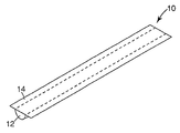
도 2는 본 개시내용의 마스킹 물품의 사시도이다;2 is a perspective view of a masking article of the present disclosure;
도 3a는 본 개시내용의 마스킹 물품의 사시도이다;3A is a perspective view of a masking article of the present disclosure;
도 3b는 본 개시내용의 마스킹 물품의 사시도이다;3B is a perspective view of a masking article of the present disclosure;
도 3c는 본 개시내용의 마스킹 물품의 사시도이다;3C is a perspective view of a masking article of the present disclosure;
도 4는 본 개시내용의 수 개의 마스킹 물품의 사시도이다;4 is a perspective view of several masking articles of the present disclosure;
도 5 ∼ 10은 기판을 마스킹하는 각종 마스킹 물품을 도시한다;5-10 illustrate various masking articles for masking substrates;
도 11은 본 개시내용의 수 개의 마스킹 물품의 측면도이다.11 is a side view of several masking articles of the present disclosure.
본 개시내용은 도장 부위와 비도장 부위 사이에 페더 에지 또는 부드러운 에지를 제공하는, 프로파일형 마스킹 물품 및 처리되거나 도장될 기판의 마스킹 방법에 관한 것이다. 본원에 기재된 마스킹 물품은 단일 스트립으로서, 또는 상이한 유형의 처리 사이에 스트립이 제거되는, 병렬 배치 다중 스트립으로서 사용될 수 있다. 이로서 다음에 이어지는 처리 층이 이전의 층을 완전히 피복한다.The present disclosure relates to a profiled masking article and a method of masking a substrate to be treated or painted, which provides a feather edge or a smooth edge between the painted and unpainted sites. The masking articles described herein can be used as single strips or as parallel batch multiple strips in which strips are removed between different types of treatment. This allows the next treatment layer to completely cover the previous layer.
본원에 기재된 마스킹 물품은 임의의 마스킹 작업에 사용될 수 있는 반면, 본 마스킹 물품은 자동차의 인접한 패널, 예컨대 도어 잼 (door jamb)의 틈을 마스킹하는 데 특히 더 할 나위 없이 적절하다.The masking articles described herein can be used for any masking operation, while the masking articles are particularly suitable for masking gaps in adjacent panels of automobiles, such as door jambs.
부분 도장될 차량의 표면과 같은 기판을 처리하기 위한 자동차 보수 작업에 사용되는 전형적인 절차는 기판에 프라이머/실러의 초벌 코팅, 이어서 칼라 코팅 (또는 도료 층), 이어서 투명 코트 층을 도포하는 것을 포함한다. 이제 도 1a를 살펴보면, 종래 기술의 마스킹 방법이 도시되어 있으며, 여기서 기판 (28)을 마스킹하기 위해 사용되는 마스킹재 (17)의 단일 단편의 사용으로 제 1 프라이머/실러 층 (22)이 마스킹재를 향해 가장 안쪽으로 침투하고, 후속으로 적용된 각 층 (24 및 26)은 더 적은 정도로 침투한다. 이는 프라이머/실러 층 (21)의 말단 에지가 후속 처리 층으로 피복되지 않은채 남아있게 하여, 흐리고, 흠이 있는 외관을 초래한다. 부드럽게 마감된 에지 또는 "페더 (feather)" 에지를 얻기 위하여, 표면은 샌딩되고/되거나 재도장되어야 하고, 이는 실질적으로 보수 시간 및 노동력을 추가하는 것이다.Typical procedures used in automotive repair operations to treat substrates, such as the surface of a vehicle to be partially painted, include applying a primer / sealer first coating followed by a color coating (or paint layer) followed by a transparent coat layer. . Referring now to FIG. 1A, a masking method of the prior art is shown wherein the first primer /
도 1b는 통상의 마스킹 테이프 (19)로 마스킹될 경우, 프라이머/실러층 (22), 칼라 코트층 (24), 및 투명 코트층 (26)을, 도장될 기판 (28)에 도포하는 경우에 수득된 코팅 프로파일을 예시한다. 통상의 마스킹 테이프 (19)의 사용은 높은 에지 프로파일 또는 메니스커스 (18)를 초래하는데, 이는 부드러운 마감을 달성하기 위하여 전형적으로 샌딩되고 재도장되어야 한다.1B shows that when masked with a
이제 도 2를 살펴보면, 본 개시내용의 하나의 실시양태에 따른 마스킹 물품의 사시도가 도시되어 있다. 마스킹 물품 (10)은 일반적으로 기다란 본체부 (12) 및 상기 본체부 (12)의 표면에 부착된 정상부 (14)를 갖는다.Referring now to FIG. 2, there is shown a perspective view of a masking article in accordance with one embodiment of the present disclosure. Masking
하나의 실시양태에서, 마스킹 물품의 본체부 (12)는, 적어도 부분적으로, 접착 재료로 이루어진다. 또다른 실시양태에서, 본체부 (12)는 전적으로 접착 재료로 이루어지고, 캐스팅 공정, 핫 멜트 (hot melt) 공정 등을 비롯한 많은 적절한 공정에 의해 형성된다.In one embodiment, the
당업자가 인지할 수 있는 바와 같이, 마스킹 물품의 본체부는 정사각형, 직사각형, 삼각형, 및 오각형과 같은 다각형 형태를 포함하지만 이에 국한되지 않는 다양한 적절한 형태를 취할 수 있다. 적절한 형태로서 또한 원형, 달갈형, 및 타원형을 포함하지만 이에 국한되지 않는 곡선형 또는 아치형 표면을 갖는 형태도 들 수 있다. 적절한 형태로서 추가로 아치형 부분 및 비-아치형 부분 모두를 갖는 형태, 예컨대, 비제한적인 예로서, 포물선형, 또는 늘려진 원형 (obround) 형태를 들 수 있다.As will be appreciated by those skilled in the art, the body portion of the masking article may take a variety of suitable forms, including but not limited to polygonal shapes such as squares, rectangles, triangles, and pentagons. Suitable forms also include forms having a curved or arcuate surface, including but not limited to round, dalgal, and oval. Suitable forms may additionally include forms having both arcuate and non-arched portions, such as, but not limited to, parabolic or elongated round shapes.
이제 도 3을 살펴보면, 마스킹 물품의 대안적 실시양태가 도시되어 있다. 도 3a는 정사각형 단면을 갖는 본체부 (42)를 갖는 마스킹 물품 (30)을 도시한다. 사다리꼴 단면을 갖는 본체부 (44)를 갖는 마스킹 물품 (32)이 도 3b에 도시되어 있다. 도 3c는 포물선형 단면 형태를 갖는 본체부 (46)를 갖고, 정상부를 갖지 않는 마스킹 물품 (34)을 도시한다. 기다란 마스킹 물품의 단면 형태는 이의 길이를 따라 하나 초과의 단면 형태를 가질 수 있음이 더 이해되어야 한다.Referring now to FIG. 3, an alternative embodiment of a masking article is shown. 3A shows a masking
하나의 실시양태에서, 마스킹 물품의 정상부 (14)는 일반적으로 평면하나, 정상부는 많은 적절한 형태의 형상을 취할 수 있으며, 예를 들어, 정상부는 본체부의 윤곽을 따르도록 형성될 수 있거나, 또는 임의의 적절한 형태, 비제한적인 예로서, 오목하거나, 볼록하거나, 또는 주름진 형상을 취할 수 있음이 이해되어야 한다.In one embodiment, the
정상부는 임의의 적절한 재료로 이루어질 수 있다. 하나의 실시양태에서, 정상부 (14)는 열가소성 재료로 이루어지며, 적층되거나, 본체부 (12)와 일체형 단편으로 형성된다. 일부 실시양태에서, 정상부 (14)는 미세구조 표면을 갖는다. 대안으로, 마스킹 물품은 정상부 없는 구성일 수 있다 (도 3c 참고). 상기 구성에서, 본체부의 표면은 사용자가 물품을 처리될 표면에 접착시킬 수 있도록 접착제 없이 제공될 것이다.The top can be made of any suitable material. In one embodiment, the
미세구조 표면을 갖는 정상부 (14)를 포함하는 하나의 실시양태에서, 미세구조 표면의 존재는 마스킹 물품이 저장 및 수송 동안 이형 라이너의 사용 없이 그 자체에 직접 감길 수 있게 할 수 있다.In one embodiment that includes a top 14 with a microstructured surface, the presence of the microstructured surface may allow the masking article to be wound directly onto itself without the use of a release liner during storage and transportation.
본원에서 사용시, 미세구조 표면은 3차원적 표면 특징부를 갖는 표면으로서 정의된다. 본원에서 사용시, 미세복제 (microreplicated) 표면은 네가티브 미세복제 패턴 자국을 갖는 도구 표면을 사용하여 표면 특징부를 색인 또는 캐스팅함으로써 형성된 미세구조 표면 유형으로서 정의된다. 미세구조 표면은 미국 특허 제 6,824,378호 (King 등)에 의해 기재된 바와 같은 도구에 의해 제조될 수 있다. 미세구조 표면 유형의 비제한적인 예로서 피라미드, 홈 (groove), 원뿔, 각기둥, 구, 및 타원체를 들 수 있다. 각종 미세구조 표면이 미국 특허 제 6,315,851호 (Mazurek 등)에 기재되어 있다. 하나의 실시양태에서, 마스킹 물품의 상부 표면은 홈의 그물 모양 (cross-hatched) 패턴을 포함한다.As used herein, microstructured surfaces are defined as surfaces with three-dimensional surface features. As used herein, microreplicated surfaces are defined as microstructured surface types formed by indexing or casting surface features using a tool surface with negative microreplicated pattern marks. Microstructured surfaces can be prepared by tools as described by US Pat. No. 6,824,378 (King et al.). Non-limiting examples of microstructured surface types include pyramids, grooves, cones, prisms, spheres, and ellipsoids. Various microstructured surfaces are described in US Pat. No. 6,315,851 to Mazurek et al. In one embodiment, the top surface of the masking article includes a cross-hatched pattern of grooves.
마스킹 물품의 정상부의 제조에 적절한 재료로서 광범위한 천연 및 합성 재료를 들 수 있다. 상기 재료의 비제한적인 예로서 폴리올레핀, 예컨대 폴리에틸렌, 폴리프로필렌, 폴리부텐, 또는 폴리펜텐; 폴리에스테르, 예컨대 폴리에틸렌 테레프탈레이트, 폴리부틸렌 테레프탈레이트, 또는 폴리에틸렌 나프탈레이트; 폴리아미드, 폴리티오에테르, 폴리술폰, 폴리우레탄, 폴리에테르술폰, 폴리이미드, 폴리비닐알콜, 폴리비닐클로라이드, 및 이의 조합물을 들 수 있다.Suitable materials for the manufacture of the tops of masking articles include a wide variety of natural and synthetic materials. Non-limiting examples of such materials include polyolefins such as polyethylene, polypropylene, polybutene, or polypentene; Polyesters such as polyethylene terephthalate, polybutylene terephthalate, or polyethylene naphthalate; Polyamides, polythioethers, polysulfones, polyurethanes, polyethersulfones, polyimides, polyvinylalcohols, polyvinylchlorides, and combinations thereof.
하나의 실시양태에서, 마스킹 물품의 치수는 너비 약 3/16 인치 (4.76 mm) x 두께 약 25 밀 (0.64 mm)이다. 물품의 길이는 용도에 따라 다를 것이며, 취약선 (line of weakness), 천공선, 또는 기타 적절한 수단에 의해 분리가능한 예비 절단된 단편으로 제공될 수 있다.In one embodiment, the dimensions of the masking article are about 3/16 inches (4.76 mm) wide by about 25 mils (0.64 mm) thick. The length of the article will vary depending on the application and may be provided in precut pieces that are separable by line of weakness, perforation lines, or other suitable means.
본원에 기재된 마스킹 물품의 본체부의 제조에 적절한 재료로서 광범위한 천연 및 합성 재료를 들 수 있다. 일부 실시양태에서, 마스킹재의 본체부는 전적으로 감압성 접착 재료로 이루어진다. 기타 실시양태에서, 본체부는 비접착성 재료를 주성분으로 하며, 물품을 기판에 접착시키는 PSA 재료의 층을 갖는다. 적절한 감압성 접착 재료의 비제한적인 예로서 폴리올레핀, 아크릴레이트 중합체, 천연 및 합성 고무, 실리콘 중합체, 폴리우레탄, 폴리 (비닐 에테르), 및 스티렌 블록 공중합체를 들 수 있다. PSA 재료는 본래 점착성이 있거나, 또는 점착성 부여제를 베이스 재료에 첨가하여 PSA를 형성한다. 유용한 점착성 부여제의 예로서 로진 에스테르 수지, 방향족 탄화수소 수지, 지방족 탄화수소 수지 및 테르펜 수지를 들 수 있다. 기타 재료, 예를 들어, 오일, 가소제, 산화방지제, 자외선 ("UV") 안정제, 수소첨가된 부틸 고무, 안료, 및 경화제를 특정 목적을 위해 첨가할 수 있다. 유용한 PSA에 대한 추가의 개시내용은 WO 2003017899 A 및 미국 특허 제 5,654,387호에서 찾을 수 있으며, 그 전문은 본원에서 참고로 인용한다.A wide range of natural and synthetic materials can be cited as materials suitable for the manufacture of the body portion of the masking article described herein. In some embodiments, the body portion of the masking material consists entirely of pressure sensitive adhesive material. In other embodiments, the body portion is based primarily on the non-adhesive material and has a layer of PSA material that adheres the article to the substrate. Non-limiting examples of suitable pressure-sensitive adhesive materials include polyolefins, acrylate polymers, natural and synthetic rubbers, silicone polymers, polyurethanes, poly (vinyl ethers), and styrene block copolymers. The PSA material is inherently tacky, or a tackifier is added to the base material to form the PSA. Examples of useful tackifiers include rosin ester resins, aromatic hydrocarbon resins, aliphatic hydrocarbon resins and terpene resins. Other materials such as oils, plasticizers, antioxidants, ultraviolet ("UV") stabilizers, hydrogenated butyl rubbers, pigments, and curing agents may be added for specific purposes. Further disclosures for useful PSAs can be found in WO 2003017899 A and US Pat. No. 5,654,387, which is incorporated herein by reference in its entirety.
PSA 재료는 WO 00/06637에 기재된 것과 같은 탄성 또는 강성 미소 구체를 더 함유할 수 있다.The PSA material may further contain elastic or rigid microspheres such as those described in WO 00/06637.
다양한 PSA 재료가 본 발명에 사용하기에 적절할 수 있지만, 사용되는 PSA 재료는, 기판에 도포된 후, 승온에 노출된 후에 조차도, 최소한의 접착력을 제공하는 것이 바람직하다. 사용되는 접착 재료는 기판의 층 박리를 야기하거나 접착제의 잔사를 남기지 않고 기판으로부터 깨끗하게 벗겨지는 것이 바람직하다. 또한, 상기 특성은 이형 라이너에 대한 필요성 없이 마스킹재가 그 자체에 감기는 능력을 보조한다. 상기 접착제를 제조하는 한가지 방법은 그의 사용 전에 접착 재료를 경화하거나 가교하는 것이며, 이는 하기에 더 설명된다. 기타 방법은 미국 특허 제 4,599,265호에 기재되어 있으며, 그 전문은 본원에서 참고로 인용한다.Although various PSA materials may be suitable for use in the present invention, it is desirable that the PSA materials used provide minimal adhesion even after they have been applied to the substrate and even after being exposed to elevated temperatures. The adhesive material used is preferably peeled cleanly from the substrate without causing layer peeling of the substrate or leaving residue of the adhesive. This property also aids the ability of the masking material to wind around itself without the need for a release liner. One method of making the adhesive is to cure or crosslink the adhesive material prior to its use, which is further described below. Other methods are described in US Pat. No. 4,599,265, which is incorporated herein by reference in its entirety.
본원에 기재된 마스킹 물품은 많은 공정, 예컨대 압출, 사출 성형, 다이캐스팅 또는 물품을 성형하기 위한 기타 적절한 공정에 의해 제조될 수 있다. 하나의 실시양태에서, 본원에 기재된 마스킹 물품은, 마스킹 물품의 정상부를 형성하는 재료웹 상에 본체부를 압출함으로써 제조된다. 상기 실시양태에서, 수 개의 본체부가 재료웹 상에 병렬로 압출될 것이며, 이어서 개별 물품은, 예를 들어, 롤 전환 공정 (roll converting process)에 의해 더 큰 웹으로부터 절단된다. 대안으로, 마스킹 물품의 정상부 및 본체부 모두가 압출 또는 공압출 공정에 의해 동시에 성형될 수 있다. 추가의 실시양태에서, 마스킹 물품의 정상부는 마스킹 물품의 압출된 본체부 상에 적층될 수 있다.The masking articles described herein can be made by a number of processes, such as extrusion, injection molding, die casting or other suitable process for molding the article. In one embodiment, the masking article described herein is made by extruding the body portion onto a material web that forms the top of the masking article. In this embodiment, several body parts will be extruded in parallel on the material web, and the individual articles are then cut from the larger web, for example by a roll converting process. Alternatively, both the top and body portions of the masking article may be molded simultaneously by an extrusion or coextrusion process. In further embodiments, the top of the masking article may be laminated on the extruded body portion of the masking article.
하나의 실시양태에서, 마스킹 물품의 본체부는, 본원에서 전문을 참고로 인용하는 미국 특허 공보 제 2003/0194526호에 기재된 바와 같은 캐스팅 공정에 의해 제조된다. 상기 공정은 점탄성 물품, 예컨대 감압성 접착제의 연속 제법을 제공하며, 여기서 점탄성 재료로 경화가능한 조성물이 제조 도구의 제 1 이형 표면 상에 코팅되고, 여기서 상기 제 1 이형 표면은 재사용될 수 있고 재료의 연속적 제조를 가능하게 하도록 구성된다. 제 2 이형 표면을 포함하는 기판은, 제 1 이형 표면 상에 코팅된 점탄성 재료와 접촉된다. 상기 점탄성 재료는 제 1 및 제 2 이형 표면과 접촉되어 있는 동안 부분적으로 또는 완전히 경화될 수 있다. 하나의 실시양태에서, 제 2 이형 표면은 마스킹 물품의 정상부를 이루는 시트재이다.In one embodiment, the body portion of the masking article is manufactured by a casting process as described in US Patent Publication No. 2003/0194526, which is incorporated herein by reference in its entirety. The process provides a continuous preparation of a viscoelastic article, such as a pressure sensitive adhesive, wherein a composition curable with a viscoelastic material is coated onto a first release surface of a manufacturing tool, where the first release surface can be reused and the It is configured to enable continuous manufacturing. The substrate comprising the second release surface is in contact with the viscoelastic material coated on the first release surface. The viscoelastic material may be partially or fully cured while in contact with the first and second release surfaces. In one embodiment, the second release surface is a sheet material that forms the top of the masking article.
제조 도구의 적절한 구조로는, 예를 들어, 벨트, 드럼 또는 롤러를 들 수 있다. 제조 도구는, 그것이 재료를 도구로부터 이형시키는 것을 촉진할 수 있기에 충분한 이형 특성을 제공하기 위하여 이형 재료로 구축될 수 있다. 적절한 이형 재료의 비제한적인 예로서 실리콘 및 플루오르화탄소 중합체를 들 수 있다. 대안으로, 도구는 임의의 적절한 지지 재료로 구축될 수 있으며, 제 1 이형 표면을 제공하기 위하여 이후 이형 코팅제로 코팅된다. 적절한 이형 코팅제의 비제한적인 예로서 실리콘 및 플루오르화탄소 중합체를 들 수 있다.As a suitable structure of a manufacturing tool, a belt, a drum, or a roller is mentioned, for example. The manufacturing tool may be constructed of a release material to provide sufficient release properties so that it may facilitate releasing the material from the tool. Non-limiting examples of suitable release materials include silicone and fluorocarbon polymers. Alternatively, the tool may be constructed of any suitable support material and then coated with a release coating to provide a first release surface. Non-limiting examples of suitable release coatings include silicone and fluorocarbon polymers.
제조 도구의 이형 표면은 매끈하거나 또는 미세 복제되거나 거시적 복제된 (macro-replicated) 패턴과 같은 구조화 표면을 포함할 수 있다. 상기 표면은 패턴화되거나 패턴화되지 않은 임의의 적절한 구조화 표면을 포함할 수 있다. 적절한 구조화 표면의 비제한적인 예로서 웰 (well), 포켓 (pocket), 릿지 (ridge), 채널 (channel) 등을 들 수 있다. 표면의 임의의 구조는 물품에 대한 목적하는 구조화 표면의 반대 이미지일 것이다. 예를 들어, 재사용가능한 표면 상의 릿지는 물품의 표면에 채널로서 나타날 것이다.The release surface of the manufacturing tool may include a structured surface, such as a smooth or micro-replicated or macro-replicated pattern. The surface can include any suitable structured surface that is patterned or unpatterned. Non-limiting examples of suitable structured surfaces include wells, pockets, ridges, channels, and the like. Any structure of the surface will be an opposite image of the desired structured surface for the article. For example, ridges on reusable surfaces will appear as channels on the surface of the article.
또다른 적절한 제조 공정은 다공성 주형이 생성되는 것이다. 주형은 유리 비드 및 분말 에폭시 수지의 혼합물로부터 생성된다. 유리 비드 및 에폭시는 함께 혼합하여 수형 (male) 도구 상에 위치시킨다. 열 및 압력을 가하여 에폭시 수지를 유동시키며 이를 경화시킨다. 에폭시 대 유리 비드의 비율은 생성되는 주형이 치수 안정성이면서 다공성이도록 선택한다. 이형 필름을 주형의 표면에 (임의로 열을 가하면서) 도포하고, 주형을 통해 진공을 가하여, 이형 시트를 주형의 공동에 합치되게 한다. 이형 시트는 실리콘과 같은 이형 층으로 코팅된 성형가능한 시트일 수 있다. PSA 조성물을 주형에서 성형된 이형 시트에 도포한다. 마스킹 물품의 정상부를 PSA에 적용하며, PSA는 열 처리를 통해 또는 화학선 복사에 의해 경화된다. Another suitable manufacturing process is the creation of a porous template. The mold is produced from a mixture of glass beads and powder epoxy resin. The glass beads and the epoxy are mixed together and placed on a male tool. Heat and pressure are applied to flow the epoxy resin and cure it. The ratio of epoxy to glass beads is chosen such that the resulting mold is both dimensionally stable and porous. The release film is applied to the surface of the mold (optionally applying heat) and vacuum is applied through the mold to bring the release sheet into conformity to the cavity of the mold. The release sheet may be a moldable sheet coated with a release layer such as silicone. The PSA composition is applied to a release sheet molded in a mold. The top of the masking article is applied to the PSA, which is cured through heat treatment or by actinic radiation.
하나의 실시양태에서, 마스킹 물품의 본체부를 이루는 점탄성 재료는 제 1 이형 표면과 접촉되어 있는 동안 부분적으로 경화되며, 이어서 마스킹 물품의 정상부를 이루는 시트재와 접촉된다. 그 후, 본체부는 완전히 경화된다. 접착 재료의 경화를 용이하게 하기 위하여, 시트재는 투명 또는 반투명일 수 있다. 상기 조립 방법은 유리한데, 왜냐하면 부분 경화된 재료는 점착성이 있어서 점탄성 재료와 마스킹 물품의 정상부를 이루는 시트재 사이의 접착을 촉진하기 때문이다. 이러한 방식으로, 마스킹 물품의 정상부를 이루는 시트재를 본체부에 접착시키기 위하여 추가의 접착제를 사용할 필요가 없다.In one embodiment, the viscoelastic material constituting the body portion of the masking article is partially cured while in contact with the first release surface and then contacted with the sheet material constituting the top of the masking article. Thereafter, the body portion is completely cured. To facilitate curing of the adhesive material, the sheet material may be transparent or translucent. The assembly method is advantageous because the partially cured material is tacky to promote adhesion between the viscoelastic material and the sheet material forming the top of the masking article. In this way, there is no need to use an additional adhesive to adhere the sheet material forming the top of the masking article to the body portion.
상기 실시양태에서, 마스킹 물품의 정상부를 이루는 시트재는 제 2 이형 표면으로서 작용한다. 본체부가 마스킹 물품의 정상부를 이루는 재료로 성공적으로 전달되는 것을 보장하기 위하여, 제 1 이형 표면 (또는 제조 도구)은 제 2 이형 표면의 표면 에너지보다 낮은 표면 에너지를 갖는다. 따라서, 경화된 조성물은 시트재가 제 1 이형 표면으로부터 분리되는 경우 시트재에 우선적으로 접착될 것이다. In this embodiment, the sheet material forming the top of the masking article acts as the second release surface. In order to ensure that the body portion is successfully delivered to the material making up the top of the masking article, the first release surface (or manufacturing tool) has a surface energy lower than the surface energy of the second release surface. Thus, the cured composition will preferentially adhere to the sheet material when the sheet material is separated from the first release surface.
경화성 조성물은 열, 적외선, 자외선, 가시광선 또는 전자빔 복사를 포함하지만 이에 국한되지 않는 임의의 적절한 경화 수단을 이용하는 에너지원에 의해 경화될 수 있다. 본원에서 사용시, 적외선 복사는 약 800 나노미터 ∼ 약 3 밀리미터 범위 이내의 파장을 갖는 비-입자성 복사를 말한다. 본원에서 사용시, 자외선 복사는 약 200 ∼ 약 400 나노미터 범위 이내의 파장을 갖는 비-입자성 복사를 말한다. 본원에서 사용시, 가시광선 복사는 약 400 ∼ 약 800 나노미터 범위 이내의 파장을 갖는 비-입자성 복사를 말한다. 전자빔 복사는 약 0.1 ∼ 약 10 Mrad 범위 이내의 조사량을 갖는다.The curable composition may be cured by an energy source using any suitable curing means, including but not limited to heat, infrared, ultraviolet, visible or electron beam radiation. As used herein, infrared radiation refers to non-particulate radiation having a wavelength within the range of about 800 nanometers to about 3 millimeters. As used herein, ultraviolet radiation refers to non-particulate radiation having a wavelength within the range of about 200 to about 400 nanometers. As used herein, visible light radiation refers to non-particulate radiation having a wavelength within the range of about 400 to about 800 nanometers. Electron beam radiation has a dosage in the range of about 0.1 to about 10 Mrad.
주어진 복사 수준에서의 경화 속도는 밀도, 온도, 및 경화성 조성물의 특성뿐만 아니라 마스킹 물품의 정상부를 이루는 재료의 투과 특성에 따라 다를 것이다. 마스킹 물품의 정상부를 이루는 재료와 접촉되어 있는 경화성 조성물의 표면이 제조 도구와 접촉되어 있는 경화성 조성물보다 더 높은 정도로 경화되도록 경화를 조절하는 것이 가능할 것이다. 상기 경화의 조절은 경화되는 조성물에 특정 용도에 바람직한 이형 특성을 제공할 수 있는데, 왜냐하면, 일반적으로, 부분 경화된 조성물은 완전 경화된 조성물보다 이형 표면으로부터 더 용이하게 제거될 수 있기 때문이다.The rate of cure at a given radiation level will depend on the density, temperature, and properties of the curable composition as well as the permeation properties of the material that forms the top of the masking article. It will be possible to adjust the cure so that the surface of the curable composition in contact with the material making up the top of the masking article is cured to a higher degree than the curable composition in contact with the manufacturing tool. Control of such curing can provide the composition to be cured with desirable release properties for a particular use, because in general, the partially cured composition can be more easily removed from the release surface than the fully cured composition.
이제 도 4를 살펴보면, 제조 도구의 제 1 이형 표면으로부터 나올 수 있는 수 개의 마스킹 물품 (20)이 사시도로 도시되어 있고, 이때 각 물품의 인접한 정상부 (14)는 천공선 (16)을 통해 또는 종래 기술에 공지된 기타 수단에 의해 부착되어 있다. 사용시, 마스킹재의 하나 이상의 스트립은, 마스킹될 물품 상의 적절한 정렬을 보장하기 위하여, 천공선 (16) 또는 기타 수단을 통해 함께 유지될 수 있다.Referring now to FIG. 4, there are shown in perspective view several masking
대안으로, 마스킹 물품은 도 11에 도시된 바와 같이 개별 마스킹 물품 (10)이 예비-마스크 테이프 (52)에 의해 함께 유지되도록 제공될 수 있다. 예비-마스크 테이프는, 마스킹 물품의 본체부가 기판에 접착되는 경우 상기 예비-마스크 테이프가 용이하게 제거되도록, 매우 낮은 접착력을 갖는 재료이다.Alternatively, the masking article may be provided such that the
하나의 실시앙태에서, 시트재 (15)는 본체부 (12)를 이루는 재료의 단편의 표면 상에 적층된다. 이상적으로는 본체부 (12)를 이루는 재료의 단편은 이들이 시트재 (15)와 접촉되는 경우 부분적으로 경화된다. 일단 시트재 (15)가 마스킹 물품의 본체부 (12)를 이루는 재료의 단편 상에 적층되면, 본체부는 완전히 경화된다. 경화시, 마스킹 물품의 본체부 (12)는 시트재 (15)에 접착된다. 이 시점에서, 라인 (16)을 따라 시트재 (15)를 절단하거나 금을 그어 정상부 (14) 및 본체부 (12)를 갖는 개별 마스킹 물품 (10)을 제조한다. 대안으로, 시트재는 2개 이상의 본체부 (12)가 함께 유지되도록 절단될 수 있다.In one embodiment, the
본 개시내용은 또한 마스킹될 표면 및 처리되거나 도장될 표면을 갖는 기판의 마스킹 방법에 관한 것이다. 이제 도 5를 살펴보면, 마스킹될 표면 (27) 및 처리될 표면 (29)을 갖는 기판 (28)이 도시되어 있다. 본체부 (12)가 마스킹될 기판의 표면 (27)에 접착된 상태의 수 개의 마스킹 물품 (10a, 10b, 및 10c)이 측면도로 도시되어 있다. 마스킹 물품 (10a, 10b, 및 10c)의 정상부 (14)는 천공선 (16), 취약선 또는 종래 기술에 공지된 기타 적절한 수단을 통해 함께 유지된다. 제 1 도료 또는 기타 처리층 (22)이 처리될 기판의 표면 (29)에 도포된다. 하나의 실시양태에서, 제 1 처리층은 프라이머 또는 실란트 재료이다. 도포시, 제 1 처리 층 (22)은 제 1 마스킹 물품 (10a)의 본체부 (12)의 선단 에지로 침투한다. 제 1 처리 층 (22) 및 후속 처리 층 (24, 26)은 적절하게는 다음 층의 도포 전에 건조될 수 있다.The present disclosure also relates to a method of masking a substrate having a surface to be masked and a surface to be treated or painted. Referring now to FIG. 5, a
제 1 처리 층 (22)이 도포된 후, 제 1 마스킹 물품 (10a)은, 마스킹 물품 (10a 및 10b)을 연결시키는 제 1 천공선 (16) (또는 취약선)을 따라 제거된다. 그 후, 제 2 처리 층 (24)이 기판 (28)의 제 1 처리 층 (22) 상에 도포된다. 제 2 처리 층 (24)은 제 2 마스킹 물품 (10b)의 본체부 (12)의 선단 에지로 침투하여, 이에 따라 제 1 처리 층 (22)을 완전히 피복한다. 하나의 실시양태에서, 제 2 처리 층 (24)은 도료 재료이다. After the
제 2 처리 층 (24)이 도포된 후, 제 2 마스킹 물품 (10b)은, 마스킹 물품 (10b 및 10c)을 연결시키는 제 2 천공선 (16) (또는 취약선)을 따라 제거된다. 그 후, 제 3 처리 층 (26)이 기판의 제 2 처리 층 (24) 상에 도포된다. 제 3 처리 층 (26)은 제 2 마스킹 물품 (10c)의 본체부 (12)의 선단 에지로 침투하여, 이에 따라 제 2 처리 층 (24)을 완전히 피복한다. 하나의 실시양태에서, 제 3 처리 층 (24)은 투명 코트 재료이다.After the
당업자가 인지할 수 있는 바와 같이, 각 처리 층이 도포된 후에 순차적으로 제거되는, 하나 이상의 병렬 배치 마스킹 물품을 사용하여, 다수의 처리 층을 본원에 기재된 방법에 따라 기판에 도포할 수 있다. As will be appreciated by those skilled in the art, multiple treatment layers may be applied to a substrate according to the methods described herein using one or more parallel batch masking articles, which are sequentially removed after each treatment layer has been applied.
도 8 및 9는, 기판 (28)에 적용된, 부착되지 않은 정상부 (14)가 제공된 개별 마스킹 물품 (10e 및 10d)을 도시한다. 이렇게 제공된 마스킹 물품은 취약선 또는 천공선을 통해 연결된 물품과 동일한 방식으로 사용될 수 있다. 대안으로, 마스킹 물품은 도 11에 도시된 바와 같이, 사용자가 마스킹 물품을 기판에 위치시키게 할 수 있는 예비-마스크 테이프에 의해 수 개의 마스킹 물품 (10)이 함께 유지되도록 제공될 수 있다. 일단 예비-마스크가 제거되면, 개별 마스킹 물품은 기판으로부터 용이하게 제거될 수 있다.8 and 9 show
당업자가 인식할 수 있는 바와 같이, 본 개시내용의 마스킹 물품 (10)은, 도 10에 도시되어 있는 바와 같이, 기타 마스킹 물품과 함께 사용될 수 있다. 도 10은 추가의 마스킹 물품 (35)과 함께 기판 (28)에 적용된 마스킹 물품 (10)을 도시한다. 추가의 마스킹 물품 (35)은 도료 또는 기타 처리가 처리될 부위를 넘어서 기판을 코팅하는 것을 방지하도록 돕는다.As will be appreciated by those skilled in the art, the masking
달리 명시하지 않는 한, 하기 실시예에 기록된 모든 부, 백분율, 및 비율은 중량 기준이며, 실시예에 사용된 모든 시약은 미주리주, 세인트 루이스 소재의 Sigma-Aldrich Chemical Company와 같은 일반 화학 물질 공급업체로부터 입수했거나 이로부터 이용가능하며, 또는 통상의 기술에 의해 합성될 수 있다.Unless otherwise specified, all parts, percentages, and ratios reported in the examples below are by weight, and all reagents used in the examples are supplied by general chemicals such as Sigma-Aldrich Chemical Company, St. Louis, Missouri Obtained from or available from a vendor, or can be synthesized by conventional techniques.
하기 약어가 하기 실시예에 사용된다:The following abbreviations are used in the following examples:
"PEF1": 한 면이, 높이가 대략 2 밀 (51 마이크로미터)이고, 8 밀 (203 마이크로미터) 간격으로 떨어져 있으며, 높이가 3 밀 (76 마이크로미터)인, 미세복제된 그물 모양 패턴의 릿지를 갖는, 캐스팅된 5 밀 (127 마이크로미터)의 저 밀도 폴리에틸렌 필름;"PEF1": One side of a microreplicated reticulated pattern, approximately 2 mils (51 micrometers) high, 8 mils (203 micrometers) apart, and 3 mils (76 micrometers) high Cast 5 mil (127 micron) low density polyethylene film with ridges;
"PEM1": 조지아주, 둘루스 소재의 Expancel, Inc.로부터 상표명 "Expancel DE 091"로 시판되는 예비 팽창된 미소 구체;"PEM1": pre-expanded microspheres sold under the trade name "Expancel DE 091" from Expancel, Inc., Duluth, GA;
"PPF1": PEF1과 동일한 미세복제 표면을 갖는, 캐스팅된 5 밀 (127 마이크로미터)의 폴리프로필렌 필름;"PPF1": cast 5 mil (127 micron) polypropylene film having the same microreplicated surface as PEF1;
"PI1": 뉴욕주, 호손 소재의 Ciba Specialty Chemicals로부터 상표명 "Irgacure 651"로 시판되는 2,2-디메톡시-2-페닐아세토페논;"PI1": 2,2-dimethoxy-2-phenylacetophenone, sold under the trade name "Irgacure 651" from Ciba Specialty Chemicals, Hawthorne, NY;
"PI2": 2,6-비스(트리클로로메틸)-6-(4-메톡시페닐)-1,3,5-트리아진, CAS No. 3584-23-4;"PI2": 2,6-bis (trichloromethyl) -6- (4-methoxyphenyl) -1,3,5-triazine, CAS No. 3584-23-4;
"SIL1": 미시간주, 미들랜드 소재의 Dow Chemical Company로부터 상표명 "Silastic J"로 시판되는 2-성분 실리콘 수지;"SIL1": two-component silicone resin sold under the trade designation "Silastic J" from Dow Chemical Company, Midland, Michigan;
"MON1": 이소옥틸 알콜과 아크릴산과의 에스테르화로부터 제조되는 이소옥틸아크릴레이트 단량체;"MON1": isooctylacrylate monomer prepared from esterification of isooctyl alcohol with acrylic acid;
"MON2": Sigma-Aldrich Company로부터 시판되는 아크릴산;"MON2": acrylic acid sold by Sigma-Aldrich Company;
"SIL2": Dow Chemical Company로부터 상표명 "Syloff 292"로 시판되는 용제형, 주석 촉매의 실리콘."SIL2": Silicone of a solvent type, tin catalyst sold under the trade name "Syloff 292" from Dow Chemical Company.
실시예Example 1 One
실리콘 캐스팅 도구를 하기와 같이 제조하였다. 너비 1/8 인치 (3.2 mm)에 깊이 25 밀 (0.64 mm)인, 중앙-내지-중앙의 간격이 3/16 인치 (4.8 mm)인, 측벽이 15°의 각도로 바깥쪽으로 가늘어지는, 평행 사다리꼴의 홈을 하부 웹 방향으로 갖는, 6 인치 x 12 인치 (15.2 x 30.5 ㎝)의 플렉소 인쇄판을 지지 유리판에 붙였다. SIL1을 20℃에서 인쇄판에 도포하고, 주걱을 사용하여 평탄하게 하며, 상기 어셈블리를 진공 챔버 내에 10분 동안 두어 탈기시켰다. SIL1이 인쇄판을 넘어 측면으로 흐르는 것을 방지하기 위하여 에지 댐 (edge dam)을 사용하였다. 그 후, 어셈블리를 진공 챔버로부터 제거하고 실리콘이 20℃에서 24시간 동안 경화되게 하였다. 생성되는 실리콘 캐스팅 도구를 인쇄판으로부터 제거하고, SIL2의 이형 코팅제 내에 침지시키며, 과량의 이형 코팅제를 떨어내고, 그 후 캐스팅 도구를 250℉ (121℃)로 설정된 오븐 내에서 3분 동안 건조시켰다. Silicone casting tools were prepared as follows. Parallel, sidewalls tapered outward at an angle of 15 °, center-to-center spacing 3/16 inches (4.8 mm), 25 mils (0.64 mm) deep by 1/8 inch (3.2 mm) wide A 6 inch by 12 inch (15.2 x 30.5 cm) flexographic printing plate with a trapezoidal groove in the lower web direction was attached to the supporting glass plate. SIL1 was applied to the printing plate at 20 ° C., flattened with a spatula and degassed by placing the assembly in a vacuum chamber for 10 minutes. An edge dam was used to prevent SIL1 from flowing sideways beyond the plate. The assembly was then removed from the vacuum chamber and the silicone was allowed to cure at 20 ° C. for 24 hours. The resulting silicone casting tool was removed from the printing plate, immersed in the release coating of SIL2, the excess release coating was dropped, and the casting tool was then dried for 3 minutes in an oven set at 250 ° F. (121 ° C.).
0.04 중량%의 PI1을 함유하는, MON1/MON2의 96/4 중량비의 혼합물을 질소 스트림으로 탈기시킨 후, 매사추세츠주, 댄버 소재의 Osram Sylvania Company로부터 입수한, 비가시광선, 유형 "F20T8 350 BLB"를 사용하여 20℃에서 4100 cps (4.1 파스칼.초)의 점도까지 부분 경화시켰다. 추가의 0.16 중량%의 PI1 및 0.15 중량%의 PI2를 첨가하고, 균질해질 때까지 손으로 혼합하며, 부분 경화된 조성물을 실리콘 캐스팅 도구의 표면에 도포하였다. 그 후, PPF1의 시트를, 부드러운 면을 아래쪽으로 하여, 부분 경화된 조성물 상에 놓았다. 고무 롤러를 필름 상에 대어서 부분 경화된 조성물을 펴고, 기포를 제거하며, 부분 경화된 조성물을 실리콘 캐스팅 도구 내로 밀어 넣었다. 그 후, 5 mm 두께의 석영 유리판을 PPF1 상에 위치시키고, 조성물을 20분 동안 5 ㎝의 거리에서, 켄터키주, 루이스빌 소재의 General Electric Company로부터의 2개의 비가시광선, 유형 "F15T8BL"에 노출시켰다. 생성 되는 겔화 접착제를 지지 필름과 함께 실리콘 캐스팅 도구로부터 제거하고, 접착제 면을 위로 하여, 질소 세정된 챔버 내에서, 동일한 비가시광선 조건 하에 노출시킴으로써 더 경화하였다. 생성되는 캐스팅된 접착제를 접착제 띠 사이에서 개별 긴 스트립으로 가늘게 쪼갠 후, 스트립을 서로 꼬아서 3 인치 (7.6 ㎝) 코어에 롤로 감았다. 이에 따라 지지 폴리프로필렌 필름의 미세복제 표면은 이형 표면으로서 기능하였다.A 96/4 weight ratio mixture of MON1 / MON2, containing 0.04% by weight of PI1, was degassed with a stream of nitrogen and then invisible, type “F20T8 350 BLB”, obtained from Osram Sylvania Company, Danver, Massachusetts. Was partially cured at 20 ° C. up to a viscosity of 4100 cps (4.1 Pascal.sec). Additional 0.16% by weight of PI1 and 0.15% by weight of PI2 were added, mixed by hand until homogeneous, and the partially cured composition was applied to the surface of the silicone casting tool. The sheet of PPF1 was then placed on the partially cured composition with the soft side down. The rubber roller was applied on the film to straighten the partially cured composition, remove bubbles, and push the partially cured composition into the silicone casting tool. Subsequently, a 5 mm thick quartz glass plate was placed on PPF1 and the composition was placed on two invisible rays, type “F15T8BL” from General Electric Company, Louisville, KY, at a distance of 5 cm for 20 minutes. Exposed. The resulting gelling adhesive was removed from the silicone casting tool along with the supporting film and further cured by exposing the adhesive side up, in a nitrogen cleaned chamber, under the same invisible light conditions. The resulting cast adhesive was finely divided into individual long strips between the strips of adhesive, then the strips were twisted together and rolled into a 3 inch (7.6 cm) core. Thus, the microreplicated surface of the supporting polypropylene film functioned as a release surface.
실시예Example 2 2
캐스팅된 접착제의 시트를 실시예 1에 기재된 방법에 따라 제조하나, 단 꼬기 전에, 미네소타주, 세인트 폴 소재의 3M Company로부터 상표명 "SCPA Premasking Tape"로 시판되는 예비 마스크 테이프를 캐스팅된 접착제의 가늘게 쪼개진 스트립의 후부에 적층하였다. 여전히 접합되어 있는 동안, 예비 마스크 테이프를 그 후 하부의 캐스팅된 접착제의 매 3개의 스트립 사이에서 가늘게 쪼개었다. 3개-스트립의 마스킹재를, 미시간주, 힐스데일 소재의 ACT Laboratories로부터 입수한, 수직으로 세워진 차가운 감겨진 강철 문설주 시험 패널의 내부에 적용하고, 예비 마스크 테이프를 제거하였다. 펜실베니아주, 피츠버그 소재의 PPG Industries로부터 입수한 실러, "Deltron NCS 2004 Gray Sealer"를 문설주 시험 패널에 분무하고, 30분 동안 건조되게 하였다. 제 1의 긴 스트립을 제거하고, PPG Industries로부터 입수한 2층의 베이스코트, "Deltron DBU Pewter Basecoat"를 10분 있다가 문설주 패널에 분무하고, 15분 동안 건조되게 하였다. 역시 PPG Industries로부터 입수한 투명 코트, "Concept DCU 2021 Clearcoat"를 그 후 문설 주 패널에 분무하고, 15분 동안 건조되게 하였다. 제 2의 긴 스트립을 제거하고, 투명 코트의 제 2 층을 문설주 패널에 분무하였다. 상기 패널이 2시간 동안 건조되게 한 후, 제 3의 긴 스트립을 제거하여 부드러운, 페더의, 도장된 문설주를 드러내었다. A sheet of casted adhesive is prepared according to the method described in Example 1, but prior to twisting, a preliminary split of preformed mask tape, commercially available under the trade name "SCPA Premasking Tape" from 3M Company, St. Paul, Minn. Laminated to the back of the strip. While still bonded, the preliminary mask tape was then thinly split between every three strips of underlying casted adhesive. The three-strip masking material was applied to the interior of a vertically wound cold wound steel scaffold test panel obtained from ACT Laboratories, Hillsdale, Michigan, and the preliminary mask tape was removed. A sealer, "Deltron NCS 2004 Gray Sealer", obtained from PPG Industries, Pittsburgh, Pennsylvania, was sprayed onto the scaffold test panel and allowed to dry for 30 minutes. The first long strip was removed and a two-layer basecoat, “Deltron DBU Pewter Basecoat,” obtained from PPG Industries, was sprayed onto the scaffold panels for 10 minutes and allowed to dry for 15 minutes. A clear coat, also from PPG Industries, "Concept DCU 2021 Clearcoat" was then sprayed onto the Munsul main panel and allowed to dry for 15 minutes. The second long strip was removed and a second layer of clear coat was sprayed onto the scaffold panel. After allowing the panel to dry for 2 hours, the third long strip was removed to reveal a smooth, feathered, painted doorpost.
실시예Example 3 3
캐스팅된 접착제의 롤을 실시예 1에 기재된 방법에 따라 제조하나, 단 지지 필름 PPF1을 PEF1으로 대체하였다.A roll of casted adhesive was prepared according to the method described in Example 1 except the support film PPF1 was replaced with PEF1.
실시예Example 4 4
캐스팅된 접착제의 롤을 실시예 1에 기재된 방법에 따라 제조하나, 단 플렉소 인쇄판의 사다리꼴 프로파일을, 반경이 1/16 인치 (1.6 mm)이고, 3/16 인치 중앙에서 원기둥의 가장자리로부터의 현이 40 밀 (1.02 mm)로 정의된 원기둥 단면의 홈을 갖도록 기계로 제조된 알루미늄 판으로 대체하였다. 캐스팅된 우레탄 (테네시주, 차타누가 소재의 Synair로부터의 Durothane S-800)을 사용한 중간 반복 단계가 실리콘 캐스팅 도구 상의 적절한 표면 지형도를 얻기 위해 필요하다. 상기 재료의 3개의 스트립을 실시예 2에 기재된 방법에 따라 마스킹 테이프로서 사용하여, 부드러운, 페더의, 도장된 문설주를 생성하였다.A roll of casted adhesive was prepared according to the method described in Example 1 except that the trapezoidal profile of the flexographic printing plate was 1/16 inch (1.6 mm) in radius and the string from the edge of the cylinder at the center of 3/16 inch. It was replaced by an aluminum plate machined to have a groove with a cylindrical cross section defined by 40 mils (1.02 mm). An intermediate repeating step with cast urethane (Durothane S-800 from Synair, Chattanooga, Tennessee) is necessary to obtain the appropriate surface topography on the silicon casting tool. Three strips of the material were used as masking tape according to the method described in Example 2 to produce a smooth, feathered, painted scaffold.
실시예Example 5 5
캐스팅된 접착제의 롤을 실시예 4에 기재된 방법에 따라 제조하나, 단 원기둥의 단면은 반경이 1/8 인치 (3.2 mm)이고 구획 (현) 사이에 랜드 영역 (land area)이 존재하지 않는다. 상기 재료의 3개의 스트립을 실시예 2에 기재된 방법에 따라 마스킹 테이프로서 사용하여, 부드러운, 페더의, 도장된 문설주를 생성하였다.A roll of cast adhesive is prepared according to the method described in Example 4 except that the cross section of the cylinder is 1/8 inch (3.2 mm) in radius and there is no land area between the compartments (strings). Three strips of the material were used as masking tape according to the method described in Example 2 to produce a smooth, feathered, painted scaffold.
실시예Example 6 6
캐스팅된 접착제의 롤을 실시예 1에 기재된 방법에 따라 제조하나, 단 시어 블레이드 (shear blade) 유형의 혼합기를 사용하여, 0.5 중량%의 PEM1을 부분 경화된 조성물에 분산시킨 후, 상기 조성물을 실리콘 캐스팅 도구에 도포하였다. 부분 경화된 조성물에 데시케이터 내에서 진공을 가하여 비말 동반된 공기를 제거한 후 이를 실리콘 캐스팅 도구에 도포하였다.A roll of casted adhesive is prepared according to the method described in Example 1, except that 0.5% by weight of PEM1 is dispersed in the partially cured composition using a shear blade type mixer, and then the composition is It was applied to a casting tool. The partially cured composition was vacuumed in a desiccator to remove the entrained air and then applied to a silicone casting tool.
실시예Example 7 7
캐스팅된 접착제의 시트를 실시예 1에 기재된 방법에 따라 제조하나, 단 폴리프로필렌 필름의 후부를 위스콘신주, 메노모니 폴 소재의 Enercon Industries Corporation으로부터의 소형 막대 (wand), 모델 "Dyna-A-Mite"를 사용하여 코로나 처리하였다. 캐스팅된 접착제 스트립의 2개의 시트를 2개의 평평한 판 사이에 쌓고, 20℃에서 4주 동안 50 그램/㎠으로 측량하였다. 상기 모의 저장 방법 이후에, 캐스팅된 접착제의 2개 층은 쉽게 벗겨 떨어진다.A sheet of cast adhesive was prepared according to the method described in Example 1 except that the back of the polypropylene film was a small wand from Enercon Industries Corporation, Menomonial, Wisconsin, Model "Dyna-A-Mite Corona treatment. Two sheets of cast adhesive strip were stacked between two flat plates and weighed at 50 grams / cm 2 for 4 weeks at 20 ° C. After the mock storage method, the two layers of cast adhesive easily peel off.
Claims (39)
Applications Claiming Priority (2)
| Application Number | Priority Date | Filing Date | Title |
|---|---|---|---|
| US67383005P | 2005-04-22 | 2005-04-22 | |
| US60/673,830 | 2005-04-22 |
Publications (1)
| Publication Number | Publication Date |
|---|---|
| KR20080003437A true KR20080003437A (en) | 2008-01-07 |
Family
ID=36717179
Family Applications (1)
| Application Number | Title | Priority Date | Filing Date |
|---|---|---|---|
| KR1020077027056A KR20080003437A (en) | 2005-04-22 | 2006-04-17 | Masking article and method of masking a substrate to be coated |
Country Status (12)
| Country | Link |
|---|---|
| US (1) | US8399058B2 (en) |
| EP (1) | EP1871541B1 (en) |
| JP (1) | JP2008538590A (en) |
| KR (1) | KR20080003437A (en) |
| CN (1) | CN101198414A (en) |
| AT (1) | ATE510629T1 (en) |
| AU (1) | AU2006240222A1 (en) |
| BR (1) | BRPI0609989A2 (en) |
| CA (1) | CA2605519A1 (en) |
| ES (1) | ES2366803T3 (en) |
| PL (1) | PL1871541T3 (en) |
| WO (1) | WO2006115900A1 (en) |
Families Citing this family (10)
| Publication number | Priority date | Publication date | Assignee | Title |
|---|---|---|---|---|
| GB0622340D0 (en) * | 2006-11-09 | 2006-12-20 | 3M Innovative Properties Co | Masking article |
| GB0711109D0 (en) * | 2007-06-11 | 2007-07-18 | 3M Innovative Properties Co | Masking article comprising skinned foam |
| USD751358S1 (en) | 2007-11-09 | 2016-03-15 | 3M Innovative Properties Company | Masking article |
| GB0812838D0 (en) * | 2008-07-14 | 2008-08-20 | Western Donald M | Method and means for masking automotive refinishing |
| RU2527727C1 (en) * | 2010-11-18 | 2014-09-10 | 3М Инновейтив Пропертиз Компани | Methods of image application on surface and devices for their use |
| GB2486736A (en) * | 2010-12-24 | 2012-06-27 | 3M Innovative Properties Co | A masking strip having a backing and a gap filler |
| US8530021B2 (en) * | 2011-03-08 | 2013-09-10 | 3M Innovative Properties Company | Microstructured tape |
| US20140378026A1 (en) * | 2013-06-19 | 2014-12-25 | Hasbro, Inc. | Apparatus and method for shaping and extruding formable material |
| US10953424B2 (en) * | 2019-01-03 | 2021-03-23 | The Boeing Company | Flexible three-dimensional maskants |
| US10717105B1 (en) * | 2019-08-15 | 2020-07-21 | Tns Solutions | Masking strip for use in painting vehicles |
Family Cites Families (35)
| Publication number | Priority date | Publication date | Assignee | Title |
|---|---|---|---|---|
| JPS55127745U (en) * | 1979-03-07 | 1980-09-09 | ||
| JPS55127745A (en) | 1979-03-26 | 1980-10-02 | Hitachi Denshi Ltd | Bit buffer system |
| JPS58101848A (en) | 1981-12-10 | 1983-06-17 | Kasai Kogyo Co Ltd | Insulator for car |
| JPS58101849A (en) | 1981-12-14 | 1983-06-17 | Nippon Tokushu Toryo Kk | Fixing hole part for molded sound-insulating material |
| JPS58101849U (en) * | 1981-12-28 | 1983-07-11 | 柴田 良次 | glass protection version |
| JPS58101848U (en) * | 1981-12-28 | 1983-07-11 | 柴田 良次 | glass protection version |
| DE3200890A1 (en) | 1982-01-14 | 1983-07-21 | Heinz 8000 München Mack | ADDITIONAL DEVICE FOR A DENTAL ARTICULATOR FOR THE THREE-DIMENSIONAL DETERMINATION OF THE DIFFERENCES OF THE JOINT POSITIONS BETWEEN THE CENTRAL OCCLUSION AND THE CENTRAL RELATION |
| JPS58124444U (en) * | 1982-02-18 | 1983-08-24 | 日立化成工業株式会社 | conductive adhesive tape |
| US4599265A (en) | 1982-11-04 | 1986-07-08 | Minnesota Mining And Manufacturing Company | Removable pressure-sensitive adhesive tape |
| DE3313650A1 (en) * | 1983-04-15 | 1984-10-18 | Reich Spezialmaschinen GmbH, 7440 Nürtingen | DEVICE FOR PRODUCING A GRINDING BODY |
| JPS60122346A (en) | 1983-12-07 | 1985-06-29 | Hitachi Ltd | Capsule type acoustic wave generator |
| JPS60122346U (en) * | 1984-01-28 | 1985-08-17 | 大日本印刷株式会社 | adhesive sheet |
| GB8800377D0 (en) * | 1988-01-08 | 1988-02-10 | Autotype Int Ltd | Masking films |
| US4996092A (en) | 1989-02-20 | 1991-02-26 | Minnesota Mining And Manufacturing Company | Shaped foam |
| JPH0318148A (en) | 1989-06-15 | 1991-01-25 | Mitsutoyo Corp | Data transmission network system |
| US5141790A (en) * | 1989-11-20 | 1992-08-25 | Minnesota Mining And Manufacturing Company | Repositionable pressure-sensitive adhesive tape |
| JPH04370180A (en) * | 1991-06-18 | 1992-12-22 | Sekisui Chem Co Ltd | Cardlike tacky tape |
| WO1995011945A1 (en) * | 1993-10-29 | 1995-05-04 | Minnesota Mining And Manufacturing Company | Pressure-sensitive adhesives having microstructured surfaces |
| US5654387A (en) * | 1993-11-10 | 1997-08-05 | Minnesota Mining And Manufacturing Company | Pressure sensitive adhesives |
| US5658632A (en) * | 1995-05-23 | 1997-08-19 | Geocel Corporation | Masking device |
| JP3670343B2 (en) * | 1995-06-16 | 2005-07-13 | ミネソタ マイニング アンド マニュファクチャリング カンパニー | Retroreflective structure and manufacturing method thereof |
| DE29601846U1 (en) | 1996-02-03 | 1996-03-14 | Future Product Entwicklungs Un | Masking profile for painting work, especially for car bodies |
| DE29608636U1 (en) | 1996-05-11 | 1997-09-11 | Voss Chemie | Foam strips |
| GB9804967D0 (en) * | 1998-03-09 | 1998-05-06 | Minnesota Mining & Mfg | Masking materials and method of use |
| US6103152A (en) | 1998-07-31 | 2000-08-15 | 3M Innovative Properties Co. | Articles that include a polymer foam and method for preparing same |
| DE19917366A1 (en) * | 1999-04-16 | 2000-10-19 | Inst Neue Mat Gemein Gmbh | Substrate surface, useful for the production of easy clean systems, comprises a hydrolyzable compound condensate having a microstructure such that the contact angle with water or oil is increased. |
| US7078582B2 (en) | 2001-01-17 | 2006-07-18 | 3M Innovative Properties Company | Stretch removable adhesive articles and methods |
| WO2002068556A2 (en) * | 2001-02-24 | 2002-09-06 | Jevtec Limited | Foam masking tape |
| GB0109176D0 (en) | 2001-04-12 | 2001-05-30 | 3M Innovative Properties Co | Masking material and a method of masking using same |
| EP1425106A2 (en) * | 2001-08-28 | 2004-06-09 | Cardinal Ig Company | Removable protective covering |
| JP2003107224A (en) * | 2001-09-27 | 2003-04-09 | Nippon Carbide Ind Co Inc | Retroreflection sheet having swell resistance |
| US6960275B2 (en) * | 2002-04-12 | 2005-11-01 | 3M Innovative Properties Company | Method of making a viscoelastic article by coating and curing on a reusable surface |
| US6828008B2 (en) * | 2002-05-03 | 2004-12-07 | George Gruber | Adhesive tape for masking |
| US6824378B2 (en) * | 2002-05-31 | 2004-11-30 | 3M Innovative Properties Company | Microreplication tool with gas release features |
| GB0622340D0 (en) | 2006-11-09 | 2006-12-20 | 3M Innovative Properties Co | Masking article |
-
2006
- 2006-04-17 AT AT06750543T patent/ATE510629T1/en not_active IP Right Cessation
- 2006-04-17 PL PL06750543T patent/PL1871541T3/en unknown
- 2006-04-17 JP JP2008507800A patent/JP2008538590A/en active Pending
- 2006-04-17 CA CA002605519A patent/CA2605519A1/en not_active Abandoned
- 2006-04-17 AU AU2006240222A patent/AU2006240222A1/en not_active Abandoned
- 2006-04-17 KR KR1020077027056A patent/KR20080003437A/en not_active Application Discontinuation
- 2006-04-17 EP EP06750543A patent/EP1871541B1/en active Active
- 2006-04-17 US US11/912,252 patent/US8399058B2/en active Active
- 2006-04-17 ES ES06750543T patent/ES2366803T3/en active Active
- 2006-04-17 WO PCT/US2006/014536 patent/WO2006115900A1/en active Application Filing
- 2006-04-17 CN CNA2006800213552A patent/CN101198414A/en active Pending
- 2006-04-17 BR BRPI0609989-0A patent/BRPI0609989A2/en not_active IP Right Cessation
Also Published As
| Publication number | Publication date |
|---|---|
| ES2366803T3 (en) | 2011-10-25 |
| EP1871541A1 (en) | 2008-01-02 |
| ATE510629T1 (en) | 2011-06-15 |
| CN101198414A (en) | 2008-06-11 |
| EP1871541B1 (en) | 2011-05-25 |
| WO2006115900A1 (en) | 2006-11-02 |
| BRPI0609989A2 (en) | 2011-10-18 |
| US8399058B2 (en) | 2013-03-19 |
| US20080248203A1 (en) | 2008-10-09 |
| AU2006240222A1 (en) | 2006-11-02 |
| CA2605519A1 (en) | 2006-11-02 |
| PL1871541T3 (en) | 2011-09-30 |
| JP2008538590A (en) | 2008-10-30 |
Similar Documents
| Publication | Publication Date | Title |
|---|---|---|
| KR20080003437A (en) | Masking article and method of masking a substrate to be coated | |
| JP4459148B2 (en) | Release liner with fine embossed pattern | |
| AU2001227295B2 (en) | Structured release liners with improved adhesion of adhesive articles | |
| US3301741A (en) | Adhesive sheet and method of making | |
| US4986496A (en) | Drag reduction article | |
| EP1619228B1 (en) | Pressure-sensitive adhesive tape | |
| US20090053449A1 (en) | Adhesive article having improved application properties | |
| CN101522393B (en) | Method of manufacturing structured release liner | |
| JP2006070273A5 (en) | ||
| JP6581080B2 (en) | System and method for producing a textured film | |
| AU2001227295A1 (en) | Structured release liners with improved adhesion of adhesive articles | |
| EP1719807A1 (en) | Pressure-sensitive adhesive sheet | |
| JP2008138066A (en) | Removable pressure-sensitive adhesive sheet | |
| WO2004026985A1 (en) | Conformable, thick edge adhesive tape for rough surface applications | |
| KR101523321B1 (en) | Pressure-sensitive adhesive sheet with air-eliminable channels | |
| US20070246155A1 (en) | Embossed Masking Sheet With Pressure Sensitive Adhesive Regions | |
| JP2007106001A (en) | Decorative sheet having adhesive layer | |
| WO2019181216A1 (en) | Snow slip film or sheet | |
| JP4863895B2 (en) | Stain-resistant adhesive film and stain-resistant structure | |
| CA1292931C (en) | Patterned, conformable sheet material for drag reduction |
Legal Events
| Date | Code | Title | Description |
|---|---|---|---|
| WITN | Application deemed withdrawn, e.g. because no request for examination was filed or no examination fee was paid |