KR20060055152A - Multi air conditioning system - Google Patents
Multi air conditioning system Download PDFInfo
- Publication number
- KR20060055152A KR20060055152A KR1020040094621A KR20040094621A KR20060055152A KR 20060055152 A KR20060055152 A KR 20060055152A KR 1020040094621 A KR1020040094621 A KR 1020040094621A KR 20040094621 A KR20040094621 A KR 20040094621A KR 20060055152 A KR20060055152 A KR 20060055152A
- Authority
- KR
- South Korea
- Prior art keywords
- compressor
- refrigerant
- air conditioning
- conditioning system
- accumulator
- Prior art date
- Legal status (The legal status is an assumption and is not a legal conclusion. Google has not performed a legal analysis and makes no representation as to the accuracy of the status listed.)
- Ceased
Links
Images


Classifications
-
- F—MECHANICAL ENGINEERING; LIGHTING; HEATING; WEAPONS; BLASTING
- F25—REFRIGERATION OR COOLING; COMBINED HEATING AND REFRIGERATION SYSTEMS; HEAT PUMP SYSTEMS; MANUFACTURE OR STORAGE OF ICE; LIQUEFACTION SOLIDIFICATION OF GASES
- F25B—REFRIGERATION MACHINES, PLANTS OR SYSTEMS; COMBINED HEATING AND REFRIGERATION SYSTEMS; HEAT PUMP SYSTEMS
- F25B41/00—Fluid-circulation arrangements
- F25B41/40—Fluid line arrangements
-
- F—MECHANICAL ENGINEERING; LIGHTING; HEATING; WEAPONS; BLASTING
- F25—REFRIGERATION OR COOLING; COMBINED HEATING AND REFRIGERATION SYSTEMS; HEAT PUMP SYSTEMS; MANUFACTURE OR STORAGE OF ICE; LIQUEFACTION SOLIDIFICATION OF GASES
- F25B—REFRIGERATION MACHINES, PLANTS OR SYSTEMS; COMBINED HEATING AND REFRIGERATION SYSTEMS; HEAT PUMP SYSTEMS
- F25B41/00—Fluid-circulation arrangements
- F25B41/20—Disposition of valves, e.g. of on-off valves or flow control valves
-
- F—MECHANICAL ENGINEERING; LIGHTING; HEATING; WEAPONS; BLASTING
- F25—REFRIGERATION OR COOLING; COMBINED HEATING AND REFRIGERATION SYSTEMS; HEAT PUMP SYSTEMS; MANUFACTURE OR STORAGE OF ICE; LIQUEFACTION SOLIDIFICATION OF GASES
- F25B—REFRIGERATION MACHINES, PLANTS OR SYSTEMS; COMBINED HEATING AND REFRIGERATION SYSTEMS; HEAT PUMP SYSTEMS
- F25B41/00—Fluid-circulation arrangements
- F25B41/30—Expansion means; Dispositions thereof
- F25B41/37—Capillary tubes
-
- F—MECHANICAL ENGINEERING; LIGHTING; HEATING; WEAPONS; BLASTING
- F25—REFRIGERATION OR COOLING; COMBINED HEATING AND REFRIGERATION SYSTEMS; HEAT PUMP SYSTEMS; MANUFACTURE OR STORAGE OF ICE; LIQUEFACTION SOLIDIFICATION OF GASES
- F25B—REFRIGERATION MACHINES, PLANTS OR SYSTEMS; COMBINED HEATING AND REFRIGERATION SYSTEMS; HEAT PUMP SYSTEMS
- F25B2400/00—General features or devices for refrigeration machines, plants or systems, combined heating and refrigeration systems or heat-pump systems, i.e. not limited to a particular subgroup of F25B
- F25B2400/04—Refrigeration circuit bypassing means
- F25B2400/0401—Refrigeration circuit bypassing means for the compressor
-
- F—MECHANICAL ENGINEERING; LIGHTING; HEATING; WEAPONS; BLASTING
- F25—REFRIGERATION OR COOLING; COMBINED HEATING AND REFRIGERATION SYSTEMS; HEAT PUMP SYSTEMS; MANUFACTURE OR STORAGE OF ICE; LIQUEFACTION SOLIDIFICATION OF GASES
- F25B—REFRIGERATION MACHINES, PLANTS OR SYSTEMS; COMBINED HEATING AND REFRIGERATION SYSTEMS; HEAT PUMP SYSTEMS
- F25B2500/00—Problems to be solved
- F25B2500/28—Means for preventing liquid refrigerant entering into the compressor
-
- F—MECHANICAL ENGINEERING; LIGHTING; HEATING; WEAPONS; BLASTING
- F25—REFRIGERATION OR COOLING; COMBINED HEATING AND REFRIGERATION SYSTEMS; HEAT PUMP SYSTEMS; MANUFACTURE OR STORAGE OF ICE; LIQUEFACTION SOLIDIFICATION OF GASES
- F25B—REFRIGERATION MACHINES, PLANTS OR SYSTEMS; COMBINED HEATING AND REFRIGERATION SYSTEMS; HEAT PUMP SYSTEMS
- F25B2600/00—Control issues
- F25B2600/25—Control of valves
- F25B2600/2501—Bypass valves
Landscapes
- Engineering & Computer Science (AREA)
- Physics & Mathematics (AREA)
- Mechanical Engineering (AREA)
- Thermal Sciences (AREA)
- General Engineering & Computer Science (AREA)
- Air Conditioning Control Device (AREA)
- Compression-Type Refrigeration Machines With Reversible Cycles (AREA)
Abstract
본 발명은 멀티 공기조화 시스템에 관한 것으로, 특히 응축기와 압축기의 사이에서 바이패스된 고온, 고압 상태의 냉매가 그대로 압축기로 들어가는 것을 방지하여 압축기의 손상을 방지하고, 시스템의 신뢰성을 확보하여 안정적인 운영이 가능하도록 한 멀티 공기조화 시스템에 관한 것이다.The present invention relates to a multi-air conditioning system, and in particular, to prevent the damage of the compressor by preventing the refrigerant of the high temperature and high pressure state bypassed between the condenser and the compressor as it enters the compressor as it is, to ensure the reliability of the system stable operation This relates to a multi-air conditioning system that makes this possible.
이를 위하여, 하나의 실외기에 다수의 실내기가 연결된 멀티 공기조화 시스템에 있어서, 상기 멀티 공기조화 시스템의 압축기와 응축기 사이의 배관과 증발기와 어큐뮬레이터 사이의 배관을 연결하는 바이패스관이 구비된 것을 특징으로 하는 멀티 공기조화 시스템이 제공된다.To this end, in a multi air conditioning system in which a plurality of indoor units are connected to one outdoor unit, a bypass pipe connecting a pipe between a compressor and a condenser and a pipe between an evaporator and an accumulator of the multi air conditioning system is provided. A multi air conditioning system is provided.
멀티 공기조화, 바이패스, 압축기, 어큐뮬레이터, 신뢰성Multi Air Conditioning, Bypass, Compressor, Accumulator, Reliability
Description
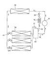
도 1은 종래 멀티 공기조화 시스템이 냉방운전 되는 상태를 나타낸 도면1 is a view showing a state in which a conventional multi-air conditioning system cooling operation
도 2는 도 1에 나타낸 어큐뮬레이터에 흡입관 및 토출관이 연결된 상태를 나타낸 단면도2 is a cross-sectional view showing a state in which a suction pipe and a discharge pipe are connected to the accumulator shown in FIG.
도 3은 본 발명의 실시예에 따른 멀티 공기조화 시스템이 냉방운전 되는 상태를 나타낸 도면3 is a view showing a state in which the multi-air conditioning system in accordance with an embodiment of the present invention the cooling operation
도 4는 도 3에 나타낸 어큐뮬레이터에 흡입관 및 토출관이 연결된 상태를 나타낸 단면도4 is a cross-sectional view showing a state in which a suction pipe and a discharge pipe are connected to the accumulator shown in FIG.
도 5는 본 발명의 다른 실시예에 따른 멀티 공기조화 시스템이 냉방운전 되는 상태를 나타낸 도면5 is a view showing a state in which the multi-air conditioning system according to another embodiment of the present invention the cooling operation
도 6은 도 5에 나타낸 어큐뮬레이터에 흡입관 및 토출관이 연결된 상태를 나타낸 단면도6 is a cross-sectional view showing a state in which a suction pipe and a discharge pipe are connected to the accumulator shown in FIG.
도면의 주요 부분에 대한 부호의 설명Explanation of symbols for the main parts of the drawings
10 : 압축기 20 : 바이패스 밸브10
30 : 응축기 40 : 팽창밸브30: condenser 40: expansion valve
50 : 증발기 60 : 어큐뮬레이터50: evaporator 60: accumulator
61 : 흡입관 62 : 토출관61
63 : 바이패스관 70 : 모세관63: bypass tube 70: capillary tube
본 발명은 멀티 공기조화 시스템에 관한 것으로, 보다 상세하게는 응축기와 압축기의 사이에서 바이패스된 고온, 고압 상태의 냉매가 그대로 압축기로 들어가는 것을 방지하여 압축기의 손상을 방지하고, 시스템의 신뢰성을 확보하여 안정적인 운영이 가능하도록 한 멀티 공기조화 시스템에 관한 것이다.The present invention relates to a multi-air conditioning system, and more particularly, to prevent damage of the compressor by preventing the refrigerant of the high temperature and high pressure state bypassed between the condenser and the compressor as it enters the compressor as it is, to ensure the reliability of the system The present invention relates to a multi-air conditioning system that enables stable operation.
일반적으로 공기조화 시스템은 1개의 실외기에 1개의 실내기가 연결되는 일반적인 공기조화 시스템과, 1개의 실외기에 다수의 실외기가 연결되는 멀티 공기조화 시스템으로 구분된다.In general, an air conditioning system is classified into a general air conditioning system in which one indoor unit is connected to one outdoor unit, and a multi air conditioning system in which a plurality of outdoor units are connected to one outdoor unit.
이하, 첨부된 도 1 및 도 2를 참조하여 종래 멀티 공기조화 시스템을 설명하면 다음과 같다.Hereinafter, a conventional multi-air conditioning system will be described with reference to FIGS. 1 and 2.
첨부된 도 1은 종래 멀티 공기조화 시스템이 냉방운전 되는 상태를 나타낸 도면이다.1 is a view illustrating a state in which a conventional multi-air conditioning system is cooled in operation.
도시된 바와 같이 종래 멀티 공기조화 시스템은 압축기(1), 응축기(3), 그리고 어큐뮬레이터(6)로 이루어진 1개의 실외기에 팽창밸브(4) 및 증발기(5)로 이루어진 다수의 실외기가 연결된다.As shown, a conventional multi-air conditioning system is connected to a plurality of outdoor units composed of an
먼저, 압축기(1)는 냉매를 흡입하여 응축압력 이상으로 압축함으로써, 고온, 고압의 기체 상태로 토출하며, 상기 압축기(1)에서 토출된 냉매의 양이 필요 이상 으로 많을 경우 냉매의 일부는 바이패스 밸브(2)를 통해 바이패스되어, 이 냉매는 다시 압축기(1)로 흡입된다.First, the compressor 1 sucks the refrigerant and compresses it to a condensation pressure or higher, thereby discharging it in a gaseous state of high temperature and high pressure. When the amount of the refrigerant discharged from the compressor 1 is more than necessary, part of the refrigerant is Bypassed through the
또한, 응축기(3)는 상기 압축기(1)에서 토출된 고온, 고압의 냉매를 흡입하여 액화시켜 토출하며, 상기 응축기(3)에서 토출된 냉매는 팽창밸브(4)를 지나면서 팽창되어 압력과 온도가 모두 떨어짐과 동시에 일부가 증발된다.In addition, the
또한, 증발기(5)는 상기 팽창밸브(4)에서 토출된 냉매를 흡입하여 주위로부터 증발에 필요한 잠열을 흡수해 이 냉매를 저온, 저압의 상태로 토출시키며, 상기 증발기(5)에서 토출된 냉매는 증발에 의해 기체와 액체가 혼합된 2상 상태이다.In addition, the
이 때, 멀티 공기조화 시스템에는 다수 개의 팽창밸브(4) 및 증발기(5)가 구비되어 전체가 동시에 작동하는 경우도 있고, 일부의 팽창밸브(4)와 증발기(5)만 작동하는 경우도 있다.In this case, the multi-air conditioning system may include a plurality of
또한, 상기 증발기(5)에서 토출된 저온, 저압의 냉매는 어큐뮬레이터(6)를 거쳐 기체와 액체를 분리시킨다.In addition, the low temperature and low pressure refrigerant discharged from the
첨부된 도 2는 도 1에 나타낸 어큐뮬레이터에 흡입관 및 토출관이 연결된 상태를 나타낸 단면도이다.2 is a cross-sectional view illustrating a state in which a suction pipe and a discharge pipe are connected to the accumulator shown in FIG. 1.
도시된 바와 같이, 상기 어큐뮬레이터(6)는 흡입관(6a)을 통해 상기 증발기(5)에서 토출된 2상 상태의 냉매를 흡입하여 하부에는 액체 상태의 냉매가 모이게 되고 상부에는 기체 상태의 냉매가 모이게 된다.As shown, the
또한, 상기 압축기(1)로 연결되는 토출관(6b)의 입구는 액체 상태인 냉매의 수면보다 높이 위치되어 기체 상태의 냉매만을 압축기(1)로 토출함으로써, 액체 상 태의 냉매가 압축기(1)로 흡입되지 않도록 하여 상기 압축기(1)가 액체 상태의 냉매에 의해 손상되는 것을 방지한다.In addition, the inlet of the
이 때, 상기 바이패스 밸브(2)에 의해 바이패스된 냉매는 바이패스관(6c)을 통해 어큐뮬레이터(6)의 토출관(6b)에 연결되어 어큐뮬레이터(6)에서 토출된 기체 상태의 냉매와 함께 압축기(1)로 흡입된다.At this time, the refrigerant bypassed by the
이와 같이 구성된 종래 멀티 공기조화 시스템은 시스템을 순환하는 냉매가 압축 및 팽창을 반복하며 증발기(5)를 통해 흡수한 열을 응축기(3)를 통해 방출하여 실내의 온도를 조절하게 된다.In the conventional multi-air conditioning system configured as described above, the refrigerant circulating in the system repeats compression and expansion, and releases the heat absorbed through the
그러나, 종래 멀티 공기조화 시스템은 일부의 팽창밸브(4) 및 증발기(5)만이 작동하는 경우에, 필요 이상의 냉매가 공급되는 것을 방지하기 위하여 일부의 냉매가 바이패스되어 상기 어큐뮬레이터(6)에서 토출된 냉매와 함께 다시 압축기(1)로 흡입되는데, 이 과정에서 다음과 같은 문제점을 가진다.However, in the conventional multi-air conditioning system, when only a part of the
상기 바이패스 밸브(2)를 통해 바이패스된 냉매는 고온, 고압의 기체 상태이고, 상기 어큐뮬레이터(6)에서 토출된 냉매는 저온, 저압의 기체 상태이고 바이패스된 냉매는 고온, 고압의 기체 상태이다.The refrigerant bypassed through the
이처럼 고온, 고압의 기체 상태인 냉매와 저온, 저압의 기체 상태인 냉매가 혼합되어 바로 상기 압축기(1)로 흡입되면 고압의 기체와 저압의 기체가 섞이는 과정에서 냉매의 온도와 압력이 급격히 상승하여 불안정한 상태로 압축기(1)에 흡입되며, 이에 따라 불안정한 고온, 고압 상태의 기체가 흡입됨에 따라 상기 압축기(1)가 손상되는 문제점을 가지는 것이다.In this way, when the refrigerant of the high-temperature, high-pressure gas state and the refrigerant of the low-temperature, low pressure gas is mixed and sucked directly into the compressor 1, the temperature and pressure of the refrigerant rises rapidly during the process of mixing the high-pressure gas and the low-pressure gas. It is sucked into the compressor 1 in an unstable state, and thus, the compressor 1 is damaged as the gas of unstable high temperature and high pressure is sucked in.
또한, 고온, 고압의 기체 상태인 냉매와 저온, 저압의 기체 상태인 냉매가 혼합되어 바로 상기 압축기(1)로 흡입되는 경우, 흡입압력 및 온도의 급격한 상승에 의해 상기 압축기(1)에서 토출되는 냉매의 압력 및 온도가 영향을 받게 되므로, 시스템의 안정적인 운영이 어려워 신뢰성이 저하되는 문제점을 가지게 된다.In addition, when the refrigerant in the gaseous state of high temperature and high pressure and the refrigerant in the gaseous state of low temperature and low pressure are mixed and sucked directly into the compressor 1, the refrigerant is discharged from the compressor 1 by a sudden rise in suction pressure and temperature. Since the pressure and temperature of the refrigerant are affected, it is difficult to operate the system stably, which causes a problem in that reliability is lowered.
이 때, 상기 바이패스 밸브(2)와 어큐뮬레이터(6)의 토출관(6b) 사이에는 바이패스된 냉매의 온도와 압력을 하강시키기 위한 모세관(7)이 설치되어 있으나, 이 모세관(7)만으로는 바이패스된 냉매의 온도와 압력을 충분히 하강시키는 것이 불가능하다.At this time, a capillary tube 7 is provided between the
이와 같은 문제점을 해결하기 위하여 상기 압축기(1)에서 토출되는 냉매의 온도가 과도하게 상승할 경우 응축기(3)에서 토출된 액체 상태의 냉매를 압축기(1) 또는 압축기(1)의 흡입관에 인젝션 하여, 액체 상태의 냉매의 증발에 따른 흡입 냉매의 온도를 하강시키는 등의 방법을 사용되기도 한다.In order to solve such a problem, when the temperature of the refrigerant discharged from the compressor 1 rises excessively, the liquid refrigerant discharged from the
그러나, 이 경우 압축기(1)에 액체 상태의 냉매가 공급되어 압축기(1)가 손상될 뿐만 아니라, 응축기(3)에서 토출된 냉매를 인젝션하는 횟수가 많아질수록 시스템의 안정적인 운영이 어려워지는 문제점을 가진다.However, in this case, the liquid refrigerant is supplied to the compressor 1, which not only damages the compressor 1, but also increases the number of injections of the refrigerant discharged from the
상기한 문제점을 해결하기 위하여, 본 발명의 목적은 압축기에서 토출된 냉매의 일부를 바이패스하여 압축기로 돌려보내더라도, 압축기가 손상되는 것을 방지할 수 있고 시스템의 안정적인 운영이 가능한 멀티 공기조화 시스템을 제공하는 것이다.In order to solve the above problems, an object of the present invention is to provide a multi-air conditioning system that can prevent the compressor from being damaged even when bypassing some of the refrigerant discharged from the compressor and returning it to the compressor. To provide.
상기의 목적을 달성하기 위하여, 본 발명은 하나의 실외기에 다수의 실내기가 연결된 멀티 공기조화 시스템에 있어서, 상기 멀티 공기조화 시스템의 압축기와 응축기 사이의 배관과 증발기와 어큐뮬레이터 사이의 배관을 연결하는 바이패스관이 구비된 것을 특징으로 하는 멀티 공기조화 시스템이 제공된다.In order to achieve the above object, the present invention provides a multi-air conditioning system in which a plurality of indoor units are connected to one outdoor unit, which connects a pipe between a compressor and a condenser and a pipe between an evaporator and an accumulator. Provided is a multi-air conditioning system, characterized in that a pass pipe is provided.
또한, 하나의 실외기에 다수의 실내기가 연결된 멀티 공기조화 시스템에 있어서, 상기 멀티 공기조화 시스템의 압축기와 응축기 사이의 배관과 어큐뮬레이터를 연결하는 바이패스관이 구비된 것을 특징으로 하는 멀티 공기조화 시스템이 제공된다.In addition, in a multi air conditioning system in which a plurality of indoor units are connected to one outdoor unit, a multi air conditioning system is provided with a bypass pipe connecting the accumulator and the pipe between the compressor and the condenser of the multi air conditioning system. Is provided.
또한, 상기 바이패스관에는 바이패스 밸브 및 모세관이 설치된다.In addition, the bypass tube is provided with a bypass valve and a capillary tube.
이하, 본 발명의 바람직한 실시예를 첨부된 도 3 내지 도 6을 참조하여 상세히 설명하면 다음과 같다.Hereinafter, preferred embodiments of the present invention will be described in detail with reference to FIGS. 3 to 6.
첨부된 도 3은 본 발명의 실시예에 따른 멀티 공기조화 시스템이 냉방운전 되는 상태를 나타낸 도면이다.3 is a view showing a state in which the multi-air conditioning system according to the embodiment of the present invention in the cooling operation.
도시된 바와 같이, 본 발명의 실시예에 따른 멀티 공기조화 시스템은 1개의 실외기에 다수의 실내기가 연결된 것으로, 압축기(10), 바이패스 밸브(20), 응축기(30), 다수의 팽창밸브(40) 및 증발기(50), 어큐뮬레이터(60), 그리고 모세관(70)을 포함하여 이루어진다.As shown, a multi-air conditioning system according to an embodiment of the present invention is a plurality of indoor units connected to one outdoor unit, the
먼저, 본 발명이 적용되는 멀티 공기조화 시스템의 압축기(10), 응축기(30), 팽창밸브(40), 그리고 증발기(50)의 기본적인 구성과 기능은 종래와 동일하며, 이 에 대한 설명은 생략하도록 한다.First, the basic configurations and functions of the
본 발명은 압축기(10)에서 토출된 냉매의 일부를 바이패스하여 압축기(10)로 돌려보내더라도 상기 압축기(10)에 흡입되는 냉매의 온도와 압력의 변화가 급격하지 않고 그 변화폭이 적게 하는 것으로서, 바이패스 밸브(20)에서 바이패스된 냉매가 압축기(10)에 바로 흡입되는 것이 아니라 어큐뮬레이터(60)를 거쳐 압축기(10)로 흡입되도록 한 것이다.According to the present invention, even if a part of the refrigerant discharged from the
첨부된 도 4는 도 3에 나타낸 어큐뮬레이터에 흡입관 및 토출관이 연결된 상태를 나타낸 단면도이다.4 is a cross-sectional view illustrating a state in which a suction pipe and a discharge pipe are connected to the accumulator shown in FIG. 3.
도시된 바와 같이, 어큐뮬레이터(60)에는 증발기(50)에서 토출된 2상 상태(기체와 액체가 혼합된 상태)의 냉매를 흡입하여 상부에는 기체 상태의 냉매가 모이게 되고, 하부에는 액체 상태의 냉매가 모이게 된다.As shown, the
또한, 어큐뮬레이터(60)의 몸체 상부에는 증발기(50)기에서 토출된 냉매를 흡입하는 흡입관(61)이 연결되고, 하부에는 냉매를 토출하여 압축기(10)로 전달하는 토출관(62)이 연결된다.In addition, a
상기 흡입관(61)에는 일부의 팽창밸브(40) 및 증발기(50)만이 사용될 경우 바이패스 밸브(20)에서 바이패스된 냉매가 흡입되는 바이패스관(63)이 연결되어, 증발기(50)에서 토출된 냉매와 바이패스된 냉매가 어큐뮬레이터(60)의 내부로 함께 흡입된다.When only a part of the
또한, 상기 토출관(62)의 입구는 어큐뮬레이터(60)의 하부에 모인 액체 상태의 냉매의 수면보다 높이 위치되어 기체 상태의 냉매만을 압축기(10)로 토출할 수 있다.In addition, the inlet of the
이와 같은 구성에 의해 바이패스 밸브(20)를 통해 바이패스된 고온, 고압 상태의 냉매는 어큐뮬레이터(60) 내부에서 증발기(50)에서 토출된 냉매와 충분히 혼합된 후, 압축기(10)로 흡입된다.The high temperature and high pressure refrigerant bypassed through the
본 발명에 따르면, 바이패스 밸브(20)를 통해 바이패스된 고온, 고압 상태의 냉매가 종래와 달리 어큐뮬레이터(60)의 흡입관(61)에 연결되어 어큐뮬레이터(60) 내부에서 증발기(50)에서 토출된 냉매와 충분히 혼합된 후 압축기(10)로 흡입되므로, 종래에 비해 압축기(10)에 흡입되는 냉매의 온도 및 압력이 낮고 상태가 안정된 상태로 흡입되도록 하여, 일부의 팽창밸브(400) 및 증발기(50)만을 사용하는 경우에 바이패스된 고온, 고압의 냉매가 의해 압축기(10)를 손상시키는 것을 방지할 수 있다.According to the present invention, the refrigerant of the high temperature and high pressure state bypassed through the
그리고, 도 5는 본 발명의 다른 실시예에 따른 멀티 공기조화 시스템이 냉방운전 되는 상태를 나타낸 도면이고, 도 6은 도 5에 나타낸 어큐뮬레이터에 흡입관 및 토출관이 연결된 상태를 나타낸 단면도로서, 바이패스관(63)이 어큐뮬레이터(60)에 직접 연결되도록 한 것이다.5 is a view illustrating a state in which a multi-air conditioning system according to another embodiment of the present invention is cooled and operated. FIG. 6 is a cross-sectional view illustrating a state in which a suction pipe and a discharge pipe are connected to the accumulator shown in FIG. 5. The
이 경우에도 첨부된 도 3 및 도 4와 마찬가지로, 바이패스 밸브(20)를 통해 바이패스된 고온, 고압 상태의 냉매는 압축기(10)로 흡입되기 전에 어큐뮬레이터(60)를 거쳐 증발기(50)에서 토출된 냉매와 충분히 혼합된다.3 and 4, the high temperature and high pressure refrigerant, which is bypassed through the
이상에서 상세히 설명한 바와 같이, 본 발명의 멀티 공기조화 시스템은 바이 패스 밸브에서 바이패스된 냉매가 어큐뮬레이터를 거쳐 압축기로 흡입되도록 하였기 때문에, 압축기에 흡입되는 냉매의 온도와 압력이 급격히 변하지 않고 변화폭도 적은 상태로 원활하게 흡입되어 압축기가 손상되는 것이 방지되어 시스템의 안정적인 운영이 가능하여 신뢰성이 향상되는 효과를 가진다.As described above in detail, the multi-air conditioning system of the present invention allows the refrigerant bypassed in the bypass valve to be sucked into the compressor through the accumulator, so that the temperature and pressure of the refrigerant sucked into the compressor do not change rapidly, and the variation is small. The suction is smoothly prevented and the compressor is prevented from being damaged, so that stable operation of the system is possible, thereby improving reliability.
Claims (4)
Priority Applications (1)
| Application Number | Priority Date | Filing Date | Title |
|---|---|---|---|
| KR1020040094621A KR20060055152A (en) | 2004-11-18 | 2004-11-18 | Multi air conditioning system |
Applications Claiming Priority (1)
| Application Number | Priority Date | Filing Date | Title |
|---|---|---|---|
| KR1020040094621A KR20060055152A (en) | 2004-11-18 | 2004-11-18 | Multi air conditioning system |
Publications (1)
| Publication Number | Publication Date |
|---|---|
| KR20060055152A true KR20060055152A (en) | 2006-05-23 |
Family
ID=37151364
Family Applications (1)
| Application Number | Title | Priority Date | Filing Date |
|---|---|---|---|
| KR1020040094621A Ceased KR20060055152A (en) | 2004-11-18 | 2004-11-18 | Multi air conditioning system |
Country Status (1)
| Country | Link |
|---|---|
| KR (1) | KR20060055152A (en) |
Cited By (3)
| Publication number | Priority date | Publication date | Assignee | Title |
|---|---|---|---|---|
| KR101372146B1 (en) * | 2007-08-27 | 2014-03-07 | (주)귀뚜라미 | Multi air conditioner improved air heating efficiency |
| WO2021100409A1 (en) * | 2019-11-22 | 2021-05-27 | 株式会社デンソー | Refrigeration cycle device |
| JP2021156567A (en) * | 2019-11-22 | 2021-10-07 | 株式会社デンソー | Refrigeration cycle device |
Citations (5)
| Publication number | Priority date | Publication date | Assignee | Title |
|---|---|---|---|---|
| JPH01314856A (en) * | 1988-06-15 | 1989-12-20 | Sanyo Electric Co Ltd | Separate type refrigerator |
| JPH03158656A (en) * | 1989-11-15 | 1991-07-08 | Toshiba Corp | Controlling method for capacity of two-cylinder compressor |
| JPH0428955A (en) * | 1990-05-25 | 1992-01-31 | Hitachi Ltd | air conditioner |
| JPH074766A (en) * | 1993-06-17 | 1995-01-10 | Mitsubishi Heavy Ind Ltd | Air-conditioning device |
| KR20040021470A (en) * | 2002-09-04 | 2004-03-10 | 위니아만도 주식회사 | Cooling system |
-
2004
- 2004-11-18 KR KR1020040094621A patent/KR20060055152A/en not_active Ceased
Patent Citations (5)
| Publication number | Priority date | Publication date | Assignee | Title |
|---|---|---|---|---|
| JPH01314856A (en) * | 1988-06-15 | 1989-12-20 | Sanyo Electric Co Ltd | Separate type refrigerator |
| JPH03158656A (en) * | 1989-11-15 | 1991-07-08 | Toshiba Corp | Controlling method for capacity of two-cylinder compressor |
| JPH0428955A (en) * | 1990-05-25 | 1992-01-31 | Hitachi Ltd | air conditioner |
| JPH074766A (en) * | 1993-06-17 | 1995-01-10 | Mitsubishi Heavy Ind Ltd | Air-conditioning device |
| KR20040021470A (en) * | 2002-09-04 | 2004-03-10 | 위니아만도 주식회사 | Cooling system |
Cited By (6)
| Publication number | Priority date | Publication date | Assignee | Title |
|---|---|---|---|---|
| KR101372146B1 (en) * | 2007-08-27 | 2014-03-07 | (주)귀뚜라미 | Multi air conditioner improved air heating efficiency |
| WO2021100409A1 (en) * | 2019-11-22 | 2021-05-27 | 株式会社デンソー | Refrigeration cycle device |
| JP2021156567A (en) * | 2019-11-22 | 2021-10-07 | 株式会社デンソー | Refrigeration cycle device |
| CN114761738A (en) * | 2019-11-22 | 2022-07-15 | 株式会社电装 | Refrigeration cycle device |
| CN114761738B (en) * | 2019-11-22 | 2024-04-09 | 株式会社电装 | Refrigeration cycle device |
| US12215900B2 (en) | 2019-11-22 | 2025-02-04 | Denso Corporation | Refrigeration cycle device |
Similar Documents
| Publication | Publication Date | Title |
|---|---|---|
| US8109111B2 (en) | Refrigerating apparatus having an intermediate-pressure refrigerant gas-liquid separator for performing refrigeration cycle | |
| JP4459776B2 (en) | Heat pump device and outdoor unit of heat pump device | |
| US8899058B2 (en) | Air conditioner heat pump with injection circuit and automatic control thereof | |
| US20100146994A1 (en) | Refrigeration apparatus and method for controlling the same | |
| US7320228B2 (en) | Refrigerant cycle apparatus | |
| US20100192607A1 (en) | Air conditioner/heat pump with injection circuit and automatic control thereof | |
| JP2002181397A (en) | refrigerator | |
| JP4550153B2 (en) | Heat pump device and outdoor unit of heat pump device | |
| EP1628088A2 (en) | Refrigerant cycle apparatus | |
| JP4704167B2 (en) | Refrigeration cycle equipment | |
| JP2016205729A (en) | Refrigeration cycle device | |
| JP2009243880A (en) | Heat pump device and outdoor unit of heat pump device | |
| KR20060055152A (en) | Multi air conditioning system | |
| JP2000346474A (en) | Refrigeration equipment | |
| KR20140123819A (en) | Air Conditioner | |
| KR100764707B1 (en) | Heat pump air conditioner and its defrost mode control method | |
| KR101397661B1 (en) | Air conditioning system | |
| KR20090069923A (en) | Air conditioning system | |
| CN108870788A (en) | Refrigerating circulatory device and liquid circulating apparatus with the refrigerating circulatory device | |
| JP2508811B2 (en) | Air conditioner | |
| CN100585285C (en) | air conditioner | |
| KR101069229B1 (en) | Refrigerant device with stabilized refrigerant circuit | |
| KR20240138139A (en) | Refrigerant circulation device and refrigerant circulation method for lowering the receiver temperature of the refrigeration cycle system | |
| KR101356348B1 (en) | Seperation-type multi air conditioner with condensor for controlling amount of refrigerants | |
| KR20040091190A (en) | Air conditioner having bypass valve |
Legal Events
| Date | Code | Title | Description |
|---|---|---|---|
| A201 | Request for examination | ||
| PA0109 | Patent application |
Patent event code: PA01091R01D Comment text: Patent Application Patent event date: 20041118 |
|
| PA0201 | Request for examination | ||
| E902 | Notification of reason for refusal | ||
| PE0902 | Notice of grounds for rejection |
Comment text: Notification of reason for refusal Patent event date: 20060428 Patent event code: PE09021S01D |
|
| PG1501 | Laying open of application | ||
| E90F | Notification of reason for final refusal | ||
| PE0902 | Notice of grounds for rejection |
Comment text: Final Notice of Reason for Refusal Patent event date: 20061026 Patent event code: PE09021S02D |
|
| E601 | Decision to refuse application | ||
| PE0601 | Decision on rejection of patent |
Patent event date: 20070212 Comment text: Decision to Refuse Application Patent event code: PE06012S01D Patent event date: 20061026 Comment text: Final Notice of Reason for Refusal Patent event code: PE06011S02I Patent event date: 20060428 Comment text: Notification of reason for refusal Patent event code: PE06011S01I |