KR20060044896A - Pressure sensor - Google Patents
Pressure sensor Download PDFInfo
- Publication number
- KR20060044896A KR20060044896A KR1020050025821A KR20050025821A KR20060044896A KR 20060044896 A KR20060044896 A KR 20060044896A KR 1020050025821 A KR1020050025821 A KR 1020050025821A KR 20050025821 A KR20050025821 A KR 20050025821A KR 20060044896 A KR20060044896 A KR 20060044896A
- Authority
- KR
- South Korea
- Prior art keywords
- diaphragm
- sensor
- pressure
- displacement
- light
- Prior art date
Links
Images


Classifications
-
- G—PHYSICS
- G01—MEASURING; TESTING
- G01L—MEASURING FORCE, STRESS, TORQUE, WORK, MECHANICAL POWER, MECHANICAL EFFICIENCY, OR FLUID PRESSURE
- G01L11/00—Measuring steady or quasi-steady pressure of a fluid or a fluent solid material by means not provided for in group G01L7/00 or G01L9/00
- G01L11/02—Measuring steady or quasi-steady pressure of a fluid or a fluent solid material by means not provided for in group G01L7/00 or G01L9/00 by optical means
-
- G—PHYSICS
- G01—MEASURING; TESTING
- G01L—MEASURING FORCE, STRESS, TORQUE, WORK, MECHANICAL POWER, MECHANICAL EFFICIENCY, OR FLUID PRESSURE
- G01L9/00—Measuring steady of quasi-steady pressure of fluid or fluent solid material by electric or magnetic pressure-sensitive elements; Transmitting or indicating the displacement of mechanical pressure-sensitive elements, used to measure the steady or quasi-steady pressure of a fluid or fluent solid material, by electric or magnetic means
- G01L9/0041—Transmitting or indicating the displacement of flexible diaphragms
- G01L9/0072—Transmitting or indicating the displacement of flexible diaphragms using variations in capacitance
-
- G—PHYSICS
- G01—MEASURING; TESTING
- G01L—MEASURING FORCE, STRESS, TORQUE, WORK, MECHANICAL POWER, MECHANICAL EFFICIENCY, OR FLUID PRESSURE
- G01L9/00—Measuring steady of quasi-steady pressure of fluid or fluent solid material by electric or magnetic pressure-sensitive elements; Transmitting or indicating the displacement of mechanical pressure-sensitive elements, used to measure the steady or quasi-steady pressure of a fluid or fluent solid material, by electric or magnetic means
- G01L9/0041—Transmitting or indicating the displacement of flexible diaphragms
- G01L9/0076—Transmitting or indicating the displacement of flexible diaphragms using photoelectric means
- G01L9/0077—Transmitting or indicating the displacement of flexible diaphragms using photoelectric means for measuring reflected light
Abstract
상당히 단단한 외측부 및 변위가능한 내측부를 포함하는 격막- 상기 내측부는 상기 격막의 제1 부분과 제2 부분 사이의 압력 차분에 응답하여 변위함 -을 포함하는 압력 게이지가 개시된다. 이러한 압력 게이지는 또한 격막에 근접하여 배치되고, 격막 내측부의 변위를 감지하는 센서를 포함한다. 이러한 압력 게이지는 또한 센서에 연결(유선 또는 무선)되고, 격막의 변위로부터 압력 차분을 결정하는 모니터/제어 시스템을 포함한다. 센서, 모니터 및 제어 시스템은 하나 이상의 광 감지 설계, 용량성 감지 설계, 또는 서브-마이크론 변위를 측정하는데 사용하는 기타 디바이스 등에 의해 구현될 수 있다. 리소그래피 애플리케이션 등 저압 애플리케이션에 대해서, 격막은 대략 0.1 내지 0.5 인치의 수압 범위의 압력 변화에 감응한다. 격막 및 센서는 비교적 높은 대역폭을 작고, 따라서 비교적 고속 애플리케이션으로 구현될 수 있다. 본 발명은 예를 들어 리소그래피 근접 감지 설비 및 리소그래피 토포그래피컬 맵핑 설비에 구현될 수 있다.A pressure gauge is disclosed that includes a diaphragm comprising a fairly rigid outer portion and a displaceable inner portion, the inner portion displacing in response to a pressure differential between the first and second portions of the diaphragm. This pressure gauge is also disposed proximate to the diaphragm and includes a sensor for sensing the displacement of the inside of the diaphragm. This pressure gauge also includes a monitor / control system that is connected (wired or wireless) to the sensor and determines the pressure differential from the displacement of the diaphragm. Sensors, monitors, and control systems can be implemented by one or more light sensing designs, capacitive sensing designs, or other devices used to measure sub-micron displacements. For low pressure applications, such as lithography applications, the diaphragm is sensitive to pressure changes in the hydraulic pressure range of approximately 0.1 to 0.5 inches. Diaphragms and sensors are relatively small in high bandwidth and thus can be implemented in relatively high speed applications. The invention can be implemented, for example, in lithographic proximity sensing equipment and lithographic topographical mapping equipment.
압력 게이지, 외측부, 내측부, 격막, 압력 차분, 센서, 모니터/제어 시스템 Pressure Gauge, Outer, Inner, Diaphragm, Pressure Differential, Sensor, Monitor / Control System
Description
도 1은 격막(102) 및 센서(104)를 포함하는 압력 센서(100)의 측면도이다.1 is a side view of a
도 2의 (a)는 격막(102)의 전면도, (b)는 격막(102)의 상당히 단단한 외측부(202)의 측면도, (c)는 상당히 단단한 외측부(202), 내측부(204) 및 근접 센서 표면(206)을 포함하는 격막(102)이 차동 압력(differential pressure) 조건 하에서 팽창된 것을 나타내는 측면도이다.(A) is a front view of the
도 3은 센서(104) 및 모니터/제어 시스템(106)이 백색광 간섭계로 구현되는 압력 센서(100)의 측면 사시도이다.3 is a side perspective view of
도 4는 센서(104) 및 모니터/제어 시스템(106)이 광 지표각 센서(optical grazing angle sensor)로 구현되는 압력 센서(100)의 측면도이다.4 is a side view of the
도 5는 센서(104)가 용량성 센서(502)를 포함하고, 근접 표면(206)이 접지 플레이트(504)를 포함하는 압력 센서(100)의 측면도이다.5 is a side view of the
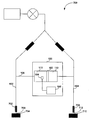
도 6은 제1 레그(602)와 제2 레그(604) 및 이들 사이의 브릿지에 배치된 압력 센서(100)를 포함하는 에어 시스템(600)의 측면도이다.FIG. 6 is a side view of an
도 7은 예를 들어 리소그래피에 사용되는 근접 센서(700)에 구현되는 압력 센서(100)의 측면도이다.7 is a side view of a
도 8은 근접 센서(800)에 구현되는 압력 센서(100)의 측면도이다.8 is a side view of the
<도면의 주요 부분에 대한 부호의 설명><Explanation of symbols for the main parts of the drawings>
100 : 압력 센서100: pressure sensor
102 : 격막102: diaphragm
104 : 센서104: sensor
106 : 모니터/제어 시스템106: Monitor / Control System
202 : 외측부202: outer part
204 : 내측부204: inner part
206 : 근접 센서 표면206: proximity sensor surface
본 발명은 고 감도, 고 대역폭, 저압 센서들에 관한 것으로, 보다 구체적으로는, 이들 디바이스를 예를 들어 리소그래피 디바이스용 에어 게이지에 적용하는 것에 관한 것이다.FIELD OF THE INVENTION The present invention relates to high sensitivity, high bandwidth, low pressure sensors, and more particularly to the application of these devices to air gauges, for example for lithographic devices.
종래의 저압 에어 게이지는 비교적 응답 시간이 적거나, 또는 대역폭이 낮은, 즉 통상적으로 수 십 ㎐ 범위의 질량 유량 센서(mass flow sensor)를 사용한다. 비교적 낮은 대역폭은 예를 들어 리소그래피 스캐닝 애플리케이션 등 고속 동작에 적합하지 않다.Conventional low pressure air gauges use a relatively low response time, or low bandwidth, mass flow sensor, typically in the tens of microseconds range. The relatively low bandwidth is not suitable for high speed operation, for example in lithographic scanning applications.
따라서, 현재 사용가능한 대역폭보다 높은 대역폭을 갖는 고 감도, 저압 에어 게이지가 요구된다.Accordingly, there is a need for a high sensitivity, low pressure air gauge with a bandwidth higher than the currently available bandwidth.
본 발명은 현재 사용가능한 대역폭보다 높은 대역폭을 갖는 고 감도, 저압 에어 게이지에 관한 것이다.The present invention relates to a high sensitivity, low pressure air gauge having a bandwidth higher than currently available bandwidth.
본 발명에 따른 압력 센서는 상당히 단단한 외측부 및 대체가능한 내측부를 갖는 격막을 포함하고, 변위가능한 내측부는 격막의 제1 부분 및 제2 부분 사이의 압력차에 응답하여 변위한다. 압력 게이지는 격막 근처에 배치되어 격막 내측부의 변위를 감지하는 센서를 더 포함한다. 압력 게이지는 센서에 연결되어(유선 또는 무선) 격막의 변위로부터 압력차를 결정하는 모니터/제어 시스템을 더 포함한다.The pressure sensor according to the invention comprises a diaphragm having a fairly rigid outer part and a replaceable inner part, the displaceable inner part displacing in response to the pressure difference between the first and second parts of the diaphragm. The pressure gauge further includes a sensor disposed near the diaphragm to sense a displacement inside the diaphragm. The pressure gauge further includes a monitor / control system connected to the sensor (wired or wireless) to determine the pressure difference from the displacement of the diaphragm.
본 발명은 광 감지 설계 및 용량성 감지 설계를 포함하는 다양한 광 감지 설계를 제공하지만 이에 제한되는 것은 아니다.The present invention provides a variety of light sensing designs, including but not limited to light sensing designs and capacitive sensing designs.
리소그래피 애플리케이션에 사용되는 나노미터 근접 센서 등 저압 애플리케이션에 대해, 센서의 동작 압력 범위는 대략 0.1 내지 0.5 인치의 수압이다. 게이지 압력 센서의 분해능은 대략 ~ 0.001 Pa로서, 이는 대략 ~ 4 x 10⁻⁵ 인치의 수압이다. 이는 게이지가 몇몇 나노미터를 분석할 수 있게 한다. 1 인치의 수압은 254 파스칼이라는 점을 참고하자.For low pressure applications, such as nanometer proximity sensors used in lithographic applications, the sensor's operating pressure range is approximately 0.1 to 0.5 inches of water pressure. The resolution of the gauge pressure sensor is approximately ˜0.001 Pa, which is approximately 4 × 10 −5 inches of water pressure. This allows the gauge to analyze several nanometers. Note that one inch of water pressure is 254 Pascals.
격막 및 센서는 비교적 높은 대역폭을 갖고, 따라서 비교적 고속 애플리케이션에 구현될 수 있다. 본 발명은 예를 들어 리소그래피 근접 감지 설비 및 리소그래피 토포그래피컬 맵핑 설비 등에 구현될 수 있다.Diaphragms and sensors have a relatively high bandwidth and can therefore be implemented in relatively high speed applications. The invention may be implemented, for example, in lithographic proximity sensing equipment and lithographic topographical mapping equipment.
이하의 설명에서 본 발명의 추가적인 특징들 및 이점들이 개시될 것이다. 본 명세서에 개시된 설명에 기초하여 당업자에게는 또 다른 특징들 및 이점들이 자명하거나 또는 본 발명의 실시에 의해 학습될 수 있을 것이다. 본 발명의 이점들은 이하 개시되는 설명 및 특허청구범위와 첨부 도면에 구체적으로 드러나는 구조에 의해 구현되고 취득될 것이다.In the following description further features and advantages of the invention will be disclosed. Other features and advantages will be apparent to one skilled in the art based on the description herein or may be learned by practice of the invention. The advantages of the invention will be realized and attained by the structure particularly pointed out in the written description and claims hereof and in the accompanying drawings.
전술한 내용 및 이하의 상세한 설명 모두는 예시적인 것이고 설명을 위한 것으로서 청구되는 본 발명에 대한 설명을 위한 것이라는 점이 이해되어야 한다.It is to be understood that both the foregoing description and the following detailed description are exemplary and illustrative of the invention as claimed for the purpose of description.
동일 참조 부호는 동일하거나 또는 기능적으로 유사한 구성요소를 지칭하는 첨주 도면을 참조하여 본 발명이 설명될 것이다. 또한, 참조 부호의 가장 좌측의 숫자는 관련 구성요소가 최초로 소개되는 도면을 나타낸다.BRIEF DESCRIPTION OF THE DRAWINGS The present invention will be described with reference to the accompanying drawings, in which like reference characters designate the same or functionally similar components. Further, the leftmost digits of the reference numerals represent the drawings in which the relevant components are first introduced.
Ⅰ. 도 입(Introduction)I. Introduction
본 발명은 현재 사용가능한 것 보다 높은 대역폭을 갖는 저압 에어 게이지에 관한 것이다. 본 발명은 예를 들어 리소그래피 근접 감지 및 리소그래피 토포그래피컬 맵핑에 사용될 수 있지만 이에 제한되는 것은 아니다.The present invention relates to a low pressure air gauge having a higher bandwidth than currently available. The invention may be used, for example, in, but not limited to, lithographic proximity sensing and lithographic topographical mapping.
Ⅱ. 고 대역폭, 저 차동 압력 감지(High Bandwidth, Low Differential Pressure Sensing)II. High Bandwidth, Low Differential Pressure Sensing
도 1은 플렉싱 플레이트 또는 격막(102), 격막(102)에 근접하여 배치되는 격막 변위 센서(104)[이하, "센서(104)"라 함], 및 센서(104)에 전기적으로 연결되는(유선 또는 무선) 모니터/제어 시스템(106)을 포함하는 압력 센서(100)의 측면도이다. 센서(104)는 격막에 근접하지만, 반드시 격막과 물리적으로 접촉하여야 하는 것은 아니다.1 is electrically connected to a flexing plate or
격막(102) 및 센서(104)는 몸체부(108) 내에서 제1 영역(110)과 제2 영역(112) 사이에 배치된다. 압력 센서(100)는 제1 영역(110)과 제2 영역(112) 사이의 압력 차분을 결정한다.The
도 2의 (a)는 격막(102)의 전면도이다. 격막(102)은 격막(102)을 몸체부(108)의 내측 벽(114)에 결합하기 위한(도 1 참조) 상당히 단단한 외측부(202)를 포함한다. 도 2의 (b)는 상당히 단단한 외측부(202)의 측면도이다. 상당히 단단한 외측부(202)는 금속, 플라스틱 또는 기타 적합한 상당히 단단한 재료나, 또는 이들의 조합으로 이루어진다.2A is a front view of the
다시 도 2의 (a)를 참조하면, 격막(102)은 제1 영역(110)과 제2 영역(112) 사이의 압력 차분에 응답하여 변위하는(도 1 참조) 변위가능한 내측부(204)를 더 포함한다.Referring again to FIG. 2A, the
내측부(204)는 예를 들어, 이에 제한되지는 않지만, 마일러(mylar), 캡톤(kapton), 러버(rubber) 및/또는 이들의 조합으로 구성되는 반-탄성(semi-elastic) 재료로 구성되는 플렉싱-플레이트, 멤브레인-기반(membrane-based) 부분이다. 내측부(204)는 저압 방향으로 팽창한다. 내측부(204)는 예를 들어, 이에 제한되지는 않지만, 대략 0.1 내지 0.5 인치의 수압 범위에 있는 매우 낮은 차동 압력에 응답하도록 설계된다. 대안적으로, 내측부(204)는 다른 압력 차분 범위에 응답하도록 설계된다.The
내측부(204)는 이에 제한되는 것은 아니지만, 접착제, 내부 형성, 열 밀봉, 화학적 접합 등을 포함하는 다양한 방식들 중 하나 이상의 방식으로 상당히 단단한 외측부(202)에 부착된다.The
내측부(204)는 근접 센서 표면(206)을 옵션으로 포함하고, 센서(104)(도 1 참조)는 근접 센서 표면(206)의 이동에 감응한다. 근접 센서 표면(206)은 내측부(204) 자체 또는 이것의 코팅물이나 주입물(impregnation)일 수 있다. 코팅물과 주입물의 예는 이하 섹션에 개시된다.The
도 2의 (c)는 상당히 단단한 외측부(202), 내측부(204) 및 근접 센서 표면(206)을 포함하는 격막(102)이 차동 압력 조건 하에서 팽창된 것을 나타내는 측면도이다.FIG. 2C is a side view showing the
도 1 및 도 2의 (a)의 예에서, 몸체부(108)는 원통 형상을 갖고, 따라서 외측부(202)는 상보형 원통 형상을 갖는다. 그러나, 본 발명이 이와 같은 원통 형상의 예로 제한되는 것은 아니다. 당업자라면 계란형, 타원형 및 다각형 등을 포함하는 기타 형태가 제한없이 이용될 수 있다는 것을 이해할 것이다.In the example of FIGS. 1 and 2 (a), the
센서(104) 및 근접 센서 표면(206)은 하나 이상의 다양한 기술로 구현될 수 있다. 센서(104) 및 근접 센서 표면(206)의 실시예들을 이하에 개시된다. 그러나, 본 발명이 이들 실시예에 제한되는 것은 아니다. 본 명세서의 교시 내용에 기초하여, 당업자라면 센서(104) 및 근접 센서 표면(206)이 본 발명의 사상 내에서 기타 기술들로 구현될 수 있다는 것을 이해할 것이다.
압력 센서(100)는 비교적 고 대역폭 디바이스이다. 채택되는 물질과 회로에 의존하여, 압력 센서는 수 천 ㎐의 대역폭을 가질 수 있다. 따라서, 본 발명은 예 를 들어, 리소그래피 근접 감지 등 비교적 저속 애플리케이션과, 예를 들어, 리소그래피 토포그래피 맵핑 등 비교적 고속 애플리케이션 양자 모두에 유용하다.
Ⅲ. 간섭계 기반 근접 감지(Interferometer Based Proximity Sensing)III. Interferometer Based Proximity Sensing
도 3은 센서(104) 및 모니터/제어 시스템(106)이 간섭계로 구현되는 압력 센서(100)의 측면 사시도이다. 간섭계는 근접 표면(206)을 반사 타겟으로 사용한다. 근접 표면(206)의 편향 변화는 센서(104)에 의해 수신되는 반사광 패턴에 대응 변화를 초래한다. 모니터/제어 시스템(106) 내의 디코더는 근접 표면(206)의 상대적 편향을 결정한다. 그리고, 모니터/제어 시스템(106)은 근접 표면(206)의 편향 측정을 제1 영역(110)과 제2 영역(112) 사이의 압력 차분으로 변환한다.3 is a side perspective view of
간섭계는 이에 제한되는 것은 아니지만 백색광 간섭계를 포함하는 기성품(off-the-shelf) 간섭계로 구현될 수 있다.The interferometer may be implemented as an off-the-shelf interferometer including, but not limited to, a white light interferometer.
Ⅳ. 광 지표각 근접 감지(Optical Grazing Angle Proximity Sensing)Ⅳ. Optical Grazing Angle Proximity Sensing
도 4는 센서(104) 및 모니터/제어 시스템(106)이 예를 들어, 본 명세서에 그 내용이 참조되는 T. Qui의 2000년 MIT 보고서 "Fiber Optics Focus Sensors: Theoretical Model"에 교시된 바와 같은 광 지표각 센서로 구현되는 압력 센서(100)의 측면도이다.4 shows that the
동작시, 제1 광 경로(402) 및 제2 광 경로(404)는 각각 송신 파이버(406)와 수신 파이버(408) 사이에 형성된다. 제1 광 경로(402)는 송신 파이버(406)와 수신 파이버(408) 사이에 있다. 제2 광 경로(404)는 송신 파이버(406)로부터 출력되고, 수신 파이버(408)에 의해 수신되기 이전에 근접 표면(206)에서 반사된다. 송신 파 이버(406)로부터 송신되어 제1 광 경로(402)를 통해 수신 파이버(408)에 의해 수신되는 제1 빔, 및 송신 파이버(406)로부터 송신되어 제2 광 경로(404)를 통해 수신 파이버(408)에 의해 수신되는 제2 빔은 공간 회절 패턴(spatial diffraction pattern)을 형성한다. 이러한 패턴은 근접 표면(206)의 상대적 위치의 함수이다.In operation, first
근접 표면(206)이 도 4에 "격막 편향(diaphragm deflection)"(410)으로 도시된 바와 같이 편향될 때, 수신 파이버(408)는 강도-변조된 광을 제2 경로(404)로부터 수신한다. 모니터/제어 시스템(106)의 디코더는 변조를 디코드하고, 근접 표면(206)의 상대적 편향을 결정한다. 그리고, 모니터/제어 시스템(106)은 근접 표면(206)의 편향 측정[즉, "격막 편향"(410)]을 제1 영역(110)과 제2 영역(112) 사이의 압력 차분으로 변환한다.When the
도 4의 예에서, 송신 파이버(406)는 광원으로부터의 광을 제1 경로(402) 및 제2 경로(404)로 분광하는 분광기를 포함한다. 대안적으로는, 파장이 음향 시프트된 2개의 송신 파이버가 사용된다. 수신 파이버(408)에서의 궁극적인 간섭 패턴은 일정하게 시프트하거나 이동한다. 근접 표면(206)이 이동하지 않을 때, 간섭 패턴은 일정한 속도로 이동한다. 근접 표면(206)이 이동할 때, 대응 시프팅 간섭 패턴의 속도가 변화한다. 모니터/제어 시스템(106)의 카운터는 패턴 변화에 기초하여 격막의 상대적 편향을 디코드한다. 그리고, 모니터/제어 시스템(106)은 근접 표면(206)의 편향 측정을 제1 영역(110)과 제2 영역(112) 사이의 압력 차분으로 변환한다.In the example of FIG. 4, the
Ⅴ. 용량성 근접 감지(Capacitive Proximity Sensing)Ⅴ. Capacitive Proximity Sensing
도 5는 센서(104)가 용량성 센서(502)를 포함하고, 근접 표면(206)이 접지 플레이트(504)를 포함하는 압력 센서(100)의 측면도이다. 접지 플레이트(504)가 적어도 부분적으로는 금속 등의 도전성 재료로 이루어진다. 용량성 센서(502)는 접지 플레이트(504)로부터 대략 300 내지 500 마이크로미터에 선택적으로 위치된다. 공기 등의 가스는 용량성 센서(502)와 접지 플레이트(504) 사이에서 유전체로서 기능하여 커패시터를 형성한다. 커패시턴스는 용량성 센서(502)로부터 접지 플레이트(504)까지의 거리의 함수이다. 모니터/제어 시스템(106)은 예를 들어, 용량성 변화에 대응하는 발진 또는 변조를 생성하는 탱크 회로 등의 회로를 포함한다. 그리고, 발진 또는 변조는 접지 플레이트(504)에 대한 상대적 편향 측정으로 변환된다. 그리고, 모니터/제어 시스템(106)은 접지 플레이트(504)의 편향 측정을 제1 영역(110)과 제2 영역(112) 사이의 압력 차분으로 변환한다.5 is a side view of the
용량성 센서는 공지된 것이고 압력 센서와 관련하여 통상적으로 사용될 수 있는 것이다.Capacitive sensors are known and can be used commonly in connection with pressure sensors.
Ⅵ. 에어 게이지로서의 압력 게이지(The Pressure Gauge as an Air Gauge)Ⅵ. The pressure gauge as an air gauge
압력 센서(100)가 선택적으로는 에어 흐름에 의해 야기되는 압력 변화를 측정하는 에어 게이지로서 구현된다. 이러한 에어 게이지는 예를 들어 이에 제한되는 것은 아니지만 리소그래피용 근접 센서들 및 리소그래피용 토포그래피컬 맵핑에 유용하다.The
도 6은 제1 레그(602)와 제2 레그(604) 및 이들 사이의 브릿지에 배치된 압력 센서(100)를 포함하는 에어 시스템(600)의 측면도이다. 압력 센서(100)는 제1 레그(602)와 제2 레그(604) 사이에 브릿지를 형성하는 몸체부(108)에 배치된다. 브릿지(108)는 각각 T-접속에 의해 제1 및 제2 레그와 연결된다.FIG. 6 is a side view of an
도 6에서, T-접속은 본질적으로 직각 T-접속이다. 그러나, 본 발명이 직각 T-접속에 제한되는 것은 아니다. 본 명세서에 기초하여, 당업자라면 다른 각도의 접속이 사용될 수 있다는 것을 이해할 것이다.In FIG. 6, the T-connection is essentially a right-angle T-connection. However, the present invention is not limited to the right angle T-connection. Based on this specification, those skilled in the art will understand that other angles of connection may be used.
제1 레그(602)와 제2 레그(604)를 통한 에어 흐름은 화살표로 도시되었다. 에어 흐름은 결국 영역(110)과 영역(112)에서 감압된다. 레그(602)에서의 에어 흐름이 레그(604)에서의 에어 흐름과 다른 경우, 영역(110)과 영역(112) 사이의 궁극적인 압력 차분은 격막(102)이 저압 영역 쪽으로 편향하게 한다. 초기 교정에 기초하여, 모니터/제어 시스템(106)은 제1 레그(602)와 제2 레그(604) 사이의 에어 흐름의 상대적 차분을 결정한다. 에어 흐름의 상대적 차분은 예를 들어 이하 설명되는 바와 같이 리소그래피 근접 감지에 사용될 수 있다.The air flow through the
Ⅶ. 리소그래피 근접 감지(Lithography Proximity Sensing)Iii. Lithography Proximity Sensing
도 7은 예를 들어 리소그래피에 사용되는 근접 센서(700)의 정면도이다. 리소그래피 근접 센서는 예를 들어 2002년 12월 19일자 출원되고 그 내용이 본 명세서에 참조되는 "High-Resoulution Gas Gauge Proximity Sensor"라는 제목의 미국 특허출원 제10/322,768호에 개시되어 있다. 또한, 에어 게이지 센서는 그 내용이 본 명세서에서 참조되며 Barda에게 1990년 9월 4일자로 허여된 "Air Gauge Sensor"라는 제목의 미국 특허 제4,953,388호에 개시되어 있다.7 is a front view of a
도 7에서, 근접 센서(700)는 제1 레그(602) 및 제2 레그(604)를 포함한다. 제1 레그(602)는 측정 프로브(702)에 연결된다. 제2 레그(604)는 기준 프로브(708)에 연결된다. 제1 레그(602)는 측정 레그이고, 제2 레그(604)는 기준 레그이다. 측정 프로브는 측정 갭(706)을 두고 웨이퍼 또는 기타 대상물(work) 표면(704)에 인접한다. 기준 프로브는 기준 갭(712)을 두고 기준 표면(710)에 인접한다.In FIG. 7,
제1 레그(602)와 제2 레그(604)의 에어 흐름이 초기에는 밸런스되어, 영역(110)과 영역(112) 사이에 에어 압력 차분을 제거한다. 측정 갭(706)이 기준 갭(712)에 비하여 변화하는 경우, 제1 레그(602)에서의 에어 흐름은 제2 레그(604)에서의 에어 흐름에 비하여 변화하여, 영역(112)에 대한 영역(110)에서의 대응 압력 변화를 초래한다. 위 섹션들에서 설명된 바와 같이 압력 변화는 압력 센서(100)에 의해 감지된다.The air flow of the
대안적으로, 기준 레그(604) 및 기준 프로브(708)는 기준 압력으로 대체된다. 예를 들어, 도 8은 근접 센서(800)의 측면도로서, 기준 레그(604)가 기준 압력(802)로 대체된다. 기준 압력(802)는 대기압 또는 제어된 압력일 수 있다.Alternatively,
Ⅶ. 결론(Conclusion)Iii. Conclusion
본 발명은 특정 기능들 및 이들의 관계를 나타내는 기능 구축 블럭들로 설명되었다. 이들 기능 구축 블럭들의 경계는 설명의 편의상 임의로 규정된다. 특정된 기능들 및 이들의 관계가 적절히 수행되기만 한다면 대안적인 경계들이 규정될 수 있다. 이러한 대안적인 경계는 따라서 본 발명의 범위 및 사상에 포함되는 것이다. 당업자라면 이들 기능 구축 블럭들이 이산 소자들, 애플리케이션 특정 집적 회로들, 적절한 소프트웨어 등을 실행하는 프로세서들 및 이들의 조합에 의해 구현될 수 있다는 것을 인식할 것이다.The present invention has been described with function building blocks that represent specific functions and their relationships. The boundaries of these functional building blocks are arbitrarily defined for convenience of description. Alternative boundaries may be defined as long as the specified functions and their relationships are properly performed. Such alternative boundaries are therefore included within the scope and spirit of the invention. Those skilled in the art will appreciate that these functional building blocks may be implemented by discrete components, application specific integrated circuits, processors executing appropriate software, and the like, and combinations thereof.
본 발명의 다양한 실시예가 설명되었으나, 이들은 오로지 예시적인 것일 뿐 제한적인 것으로 표현된 것은 아니라는 점을 이해하여야 할 것이다. 따라서, 본 발명의 폭 및 범위는 상술된 예시적인 실시예 중 어느 것에 의해서도 제한되어서는 안될 것이며, 이하의 청구범위 및 그 등가물에 따라서만 제한되어야 할 것이다.While various embodiments of the invention have been described, it will be understood that they are illustrative only and not intended to be limiting. Accordingly, the breadth and scope of the present invention should not be limited by any of the above-described exemplary embodiments, but should be limited only in accordance with the following claims and their equivalents.
본 발명에 따르면 현재 사용가능한 대역폭보다 높은 대역폭을 갖는 고 감도, 저압 에어 게이지, 리소그래피용 근접 센서 및 리소그래피 토포그래피 맵핑 디바이스 등을 제공할 수 있다.According to the present invention, it is possible to provide a high sensitivity, low pressure air gauge, a proximity sensor for lithography, a lithography topography mapping device, and the like, having a bandwidth higher than currently available bandwidth.
Claims (13)
Applications Claiming Priority (2)
| Application Number | Priority Date | Filing Date | Title |
|---|---|---|---|
| US10/812,098 | 2004-03-30 | ||
| US10/812,098 US7272976B2 (en) | 2004-03-30 | 2004-03-30 | Pressure sensor |
Related Child Applications (1)
| Application Number | Title | Priority Date | Filing Date |
|---|---|---|---|
| KR1020080063725A Division KR20080077057A (en) | 2004-03-30 | 2008-07-02 | Pressure sensor |
Publications (1)
| Publication Number | Publication Date |
|---|---|
| KR20060044896A true KR20060044896A (en) | 2006-05-16 |
Family
ID=34887676
Family Applications (2)
| Application Number | Title | Priority Date | Filing Date |
|---|---|---|---|
| KR1020050025821A KR20060044896A (en) | 2004-03-30 | 2005-03-29 | Pressure sensor |
| KR1020080063725A KR20080077057A (en) | 2004-03-30 | 2008-07-02 | Pressure sensor |
Family Applications After (1)
| Application Number | Title | Priority Date | Filing Date |
|---|---|---|---|
| KR1020080063725A KR20080077057A (en) | 2004-03-30 | 2008-07-02 | Pressure sensor |
Country Status (7)
| Country | Link |
|---|---|
| US (2) | US7272976B2 (en) |
| EP (1) | EP1582852A3 (en) |
| JP (2) | JP2005283588A (en) |
| KR (2) | KR20060044896A (en) |
| CN (2) | CN101398336A (en) |
| SG (2) | SG115819A1 (en) |
| TW (1) | TWI276791B (en) |
Cited By (1)
| Publication number | Priority date | Publication date | Assignee | Title |
|---|---|---|---|---|
| KR101045006B1 (en) * | 2009-09-17 | 2011-06-29 | 군산대학교산학협력단 | Calibration system and calibration method of multi-hole pressure probe |
Families Citing this family (21)
| Publication number | Priority date | Publication date | Assignee | Title |
|---|---|---|---|---|
| US7272976B2 (en) * | 2004-03-30 | 2007-09-25 | Asml Holdings N.V. | Pressure sensor |
| US7134321B2 (en) | 2004-07-20 | 2006-11-14 | Asml Holding N.V. | Fluid gauge proximity sensor and method of operating same using a modulated fluid flow |
| US7437938B2 (en) * | 2007-03-21 | 2008-10-21 | Rosemount Inc. | Sensor with composite diaphragm containing carbon nanotubes or semiconducting nanowires |
| US7775118B2 (en) * | 2008-04-24 | 2010-08-17 | Custom Sensors & Technologies, Inc. | Sensor element assembly and method |
| NL2003266A1 (en) * | 2008-08-11 | 2010-02-15 | Asml Holding Nv | Multi nozzle proximity sensor employing common sensing and nozzle shaping. |
| JP5349997B2 (en) * | 2009-02-10 | 2013-11-20 | 株式会社ケネック | Optical displacement meter |
| JP5669841B2 (en) * | 2009-07-31 | 2015-02-18 | エーエスエムエル ホールディング エヌ.ブイ. | Detection apparatus and method, and lithography system |
| US20110069291A1 (en) * | 2009-09-11 | 2011-03-24 | Sogard Michael R | Physical sensor for autofocus system |
| CN102062665A (en) * | 2009-11-17 | 2011-05-18 | 刘保龙 | Mirror reflection type vacuum measurement device |
| CN102824274A (en) * | 2012-08-30 | 2012-12-19 | 谭和平 | Automatic drinking bottle |
| EP2901121B1 (en) * | 2012-09-28 | 2017-03-29 | BioFluidix GmbH | Capacitive pressure sensor |
| EP2931334B1 (en) * | 2012-12-14 | 2017-08-09 | Gambro Lundia AB | Diaphragm repositioning for pressure pod using position sensing |
| NO20130884A1 (en) | 2013-06-21 | 2014-12-22 | Sinvent As | Optical offset sensor element |
| CN105092110A (en) * | 2014-05-06 | 2015-11-25 | 无锡华润上华半导体有限公司 | Pressure sensor and manufacturing method thereof |
| AU2017319613A1 (en) * | 2016-09-01 | 2019-01-17 | Alcon Inc. | Systems and methods for non-invasive measurement of cassette pressure |
| CN109414200B (en) * | 2017-12-25 | 2019-12-24 | 深圳市得道健康管理有限公司 | Surface strain detection device and surface strain sensor thereof |
| KR102039426B1 (en) * | 2018-06-22 | 2019-11-27 | 한국표준과학연구원 | Air Floating Thin Film Thickness Measuring Apparatus |
| CN108663157A (en) * | 2018-08-01 | 2018-10-16 | 桂林电子科技大学 | Michelson white light interference optical fibers hydrostatic sensor and measuring system |
| WO2020190635A1 (en) | 2019-03-15 | 2020-09-24 | Nxstage Medical, Inc. | Pressure measurement devices, methods, and systems |
| CN110082026B (en) * | 2019-03-26 | 2021-01-01 | 中山大学 | Air pressure detection device, manufacturing method thereof and air pressure detection method |
| DE102021212018B3 (en) | 2021-10-25 | 2022-11-10 | Carl Zeiss Smt Gmbh | Projection exposure system, method for operating the projection exposure system |
Family Cites Families (43)
| Publication number | Priority date | Publication date | Assignee | Title |
|---|---|---|---|---|
| DE1129317B (en) | 1960-10-14 | 1962-05-10 | Schenck Gmbh Carl | Load cell |
| FR87526E (en) * | 1964-03-06 | 1966-06-24 | Onera (Off Nat Aerospatiale) | Subminiature pressure sensor |
| FR1551179A (en) * | 1967-11-15 | 1968-12-27 | ||
| US3625616A (en) * | 1969-06-25 | 1971-12-07 | Bendix Corp | Interferometric pressure sensor |
| GB1374775A (en) | 1971-10-11 | 1974-11-20 | Bowles Fluidics Corp | Fluidic porximity sensor |
| JPS4911356A (en) * | 1972-05-31 | 1974-01-31 | ||
| US4158310A (en) * | 1978-01-30 | 1979-06-19 | University Of Southern California | Optical pressure transducer of randomly distributed fiber optics |
| DE2937485A1 (en) * | 1979-09-17 | 1981-06-19 | Siemens AG, 1000 Berlin und 8000 München | OPTICAL DEVICE FOR MEASURING LOW PRESSURE DIFFERENCES BY MEANS OF LIGHT INTENSITY CHANGE |
| US4270560A (en) * | 1979-11-19 | 1981-06-02 | Kearney John G | Photo-electric burst disc indicator |
| DE3142164A1 (en) * | 1980-10-27 | 1982-06-16 | Rosemount Engineering Co. Ltd., Bognor Regis, Sussex | DEVICE FOR MEASURING PRESSURE DIFFERENCES |
| US4521683A (en) * | 1981-03-20 | 1985-06-04 | The Boeing Company | Pressure-actuated optical switch |
| GB2102941A (en) * | 1981-06-09 | 1983-02-09 | Rosemount Eng Co Ltd | Differential pressure sensing |
| DE3206720A1 (en) * | 1982-02-25 | 1983-09-01 | Philips Patentverwaltung Gmbh, 2000 Hamburg | OPTICAL SENSOR |
| US4550592A (en) * | 1984-05-07 | 1985-11-05 | Dechape Michel L | Pneumatic gauging circuit |
| US4648082A (en) * | 1985-03-04 | 1987-03-03 | Western Geophysical Company Of America | Marine acoustic gradient sensor |
| US4665747A (en) * | 1985-04-19 | 1987-05-19 | Muscatell Ralph P | Flight instrument using light interference for pressure sensing |
| US4655086A (en) * | 1985-04-30 | 1987-04-07 | Iowa State University Research Foundation, Inc. | Method and means for measuring sound intensity |
| US4933545A (en) * | 1985-12-30 | 1990-06-12 | Metricor, Inc. | Optical pressure-sensing system using optical resonator cavity |
| JPS62168415U (en) * | 1986-04-17 | 1987-10-26 | ||
| JPS639805A (en) * | 1986-06-30 | 1988-01-16 | Hitachi Electronics Eng Co Ltd | Positioning device by liquid injection |
| JPS6421330A (en) * | 1987-07-16 | 1989-01-24 | Teijin Ltd | Pressure detector |
| US4869282A (en) * | 1988-12-09 | 1989-09-26 | Rosemount Inc. | Micromachined valve with polyimide film diaphragm |
| US4953388A (en) * | 1989-01-25 | 1990-09-04 | The Perkin-Elmer Corporation | Air gauge sensor |
| US5252826A (en) * | 1991-12-30 | 1993-10-12 | Honeywell Inc. | Differential pressure utilizing opto-reflective sensor |
| US5281782A (en) * | 1992-04-28 | 1994-01-25 | Campbell Hausfeld | Diaphragm pressure switch |
| CA2078727A1 (en) * | 1992-09-21 | 1994-03-22 | Karoly G. Nemeth | Method and apparatus for detecting thickness variations in sheet material |
| US6052613A (en) * | 1993-06-18 | 2000-04-18 | Terumo Cardiovascular Systems Corporation | Blood pressure transducer |
| US5570428A (en) * | 1994-09-27 | 1996-10-29 | Tibbetts Industries, Inc. | Transducer assembly |
| US5880841A (en) * | 1997-09-08 | 1999-03-09 | Erim International, Inc. | Method and apparatus for three-dimensional imaging using laser illumination interferometry |
| US6014239C1 (en) * | 1997-12-12 | 2002-04-09 | Brookhaven Science Ass Llc | Optical microphone |
| JP2000121323A (en) * | 1998-10-14 | 2000-04-28 | Hitachi Ltd | Inspection method for surface height and inspection device therefor, and color filter substrate and inspection method therefor and manufacturing thereof |
| US6105436A (en) * | 1999-07-23 | 2000-08-22 | Mks Instruments, Inc. | Capacitive pressure transducer with improved electrode support |
| US6496265B1 (en) * | 2000-02-16 | 2002-12-17 | Airak, Inc. | Fiber optic sensors and methods therefor |
| JP2001255225A (en) * | 2000-03-10 | 2001-09-21 | Anelva Corp | Static capacitance type vacuum sensor |
| US6738145B2 (en) * | 2000-04-14 | 2004-05-18 | Shipley Company, L.L.C. | Micromachined, etalon-based optical fiber pressure sensor |
| CN2475015Y (en) * | 2001-03-02 | 2002-01-30 | 段祥照 | Capacitance differential pressure/pressure sensor |
| AU2002256193A1 (en) * | 2001-04-11 | 2002-10-28 | Modern Optical Technologies Llc. | Method and apparatus for measuring pressure |
| US6892583B2 (en) * | 2001-10-31 | 2005-05-17 | Rheosense, Inc. | Pressure sensing device for rheometers |
| CN2537970Y (en) * | 2002-05-09 | 2003-02-26 | 奥诚喜 | Optical fibre pressure sensor |
| US20040099060A1 (en) * | 2002-11-23 | 2004-05-27 | Johan Kijlstra | Device and method for characterizing a capillary system |
| US7010958B2 (en) * | 2002-12-19 | 2006-03-14 | Asml Holding N.V. | High-resolution gas gauge proximity sensor |
| US7272976B2 (en) * | 2004-03-30 | 2007-09-25 | Asml Holdings N.V. | Pressure sensor |
| ITMI20061000A1 (en) * | 2006-05-22 | 2007-11-23 | Milano Politecnico | ELASTIC COUPLING WITH SPHERICAL HINGE TRANSLATOR AND SENSOR OF FORCES AND MOMENTS PERFECTED WITH THIS JOINT |
-
2004
- 2004-03-30 US US10/812,098 patent/US7272976B2/en not_active Expired - Fee Related
-
2005
- 2005-03-23 EP EP05006428A patent/EP1582852A3/en not_active Withdrawn
- 2005-03-28 TW TW094109658A patent/TWI276791B/en not_active IP Right Cessation
- 2005-03-29 KR KR1020050025821A patent/KR20060044896A/en not_active Application Discontinuation
- 2005-03-30 SG SG200501991A patent/SG115819A1/en unknown
- 2005-03-30 CN CNA2008101609721A patent/CN101398336A/en active Pending
- 2005-03-30 JP JP2005099342A patent/JP2005283588A/en active Pending
- 2005-03-30 SG SG200806575-7A patent/SG146616A1/en unknown
- 2005-03-30 CN CNB2005100627663A patent/CN100430707C/en not_active Expired - Fee Related
-
2007
- 2007-09-24 US US11/860,289 patent/US20080087094A1/en not_active Abandoned
-
2008
- 2008-07-02 KR KR1020080063725A patent/KR20080077057A/en not_active Application Discontinuation
- 2008-12-10 JP JP2008314267A patent/JP5033780B2/en not_active Expired - Fee Related
Cited By (1)
| Publication number | Priority date | Publication date | Assignee | Title |
|---|---|---|---|---|
| KR101045006B1 (en) * | 2009-09-17 | 2011-06-29 | 군산대학교산학협력단 | Calibration system and calibration method of multi-hole pressure probe |
Also Published As
| Publication number | Publication date |
|---|---|
| SG115819A1 (en) | 2005-10-28 |
| CN100430707C (en) | 2008-11-05 |
| CN101398336A (en) | 2009-04-01 |
| CN1680794A (en) | 2005-10-12 |
| JP2009085968A (en) | 2009-04-23 |
| EP1582852A2 (en) | 2005-10-05 |
| EP1582852A3 (en) | 2008-02-27 |
| KR20080077057A (en) | 2008-08-21 |
| TWI276791B (en) | 2007-03-21 |
| JP5033780B2 (en) | 2012-09-26 |
| US20080087094A1 (en) | 2008-04-17 |
| JP2005283588A (en) | 2005-10-13 |
| SG146616A1 (en) | 2008-10-30 |
| US7272976B2 (en) | 2007-09-25 |
| TW200535406A (en) | 2005-11-01 |
| US20050217384A1 (en) | 2005-10-06 |
Similar Documents
| Publication | Publication Date | Title |
|---|---|---|
| KR20060044896A (en) | Pressure sensor | |
| US4942767A (en) | Pressure transducer apparatus | |
| JP3150958B2 (en) | Eddy current sensor | |
| US5052228A (en) | Shear stress measuring device | |
| US7440117B2 (en) | Highly-sensitive displacement-measuring optical device | |
| US5280341A (en) | Feedback controlled differential fiber interferometer | |
| US5771091A (en) | Sensor and a method for measuring distances to, and/or physical properties of, a medium | |
| US7164479B2 (en) | Optical displacement sensor | |
| US6713743B2 (en) | Fabry-perot resonator and system for measuring and calibrating displacement of a cantilever tip using the same in atomic force microscope | |
| US20060192976A1 (en) | Highly-sensitive displacement-measuring optical device | |
| JP2009085968A5 (en) | ||
| US20020039463A1 (en) | Optical displacement sensor | |
| US20040130728A1 (en) | Highly-sensitive displacement-measuring optical device | |
| US20080186478A1 (en) | Pressure transmitter for detection of a variable relative to a process fluid | |
| US20030231319A1 (en) | Frequency splitting laser micrometer | |
| WO2005055245A1 (en) | High sensitivity scanning probe system | |
| US7096737B2 (en) | Pressure sensing apparatus | |
| US6341526B1 (en) | Micromachined diffractive pressure sensor system | |
| US7280220B2 (en) | Physical quantity measuring method and device therefor | |
| US4070902A (en) | Attachment for air gauging apparatus | |
| US5521884A (en) | Vibrating element transducer | |
| US5311014A (en) | Optical transducer for measuring pressure | |
| Chernov et al. | Analytical model of photoelectric pressure sensor | |
| RU2589946C1 (en) | Amplitude fibre-optic pressure sensor | |
| SU1296869A1 (en) | Device for dynamic testing of plain bearings |
Legal Events
| Date | Code | Title | Description |
|---|---|---|---|
| A201 | Request for examination | ||
| E902 | Notification of reason for refusal | ||
| AMND | Amendment | ||
| E601 | Decision to refuse application | ||
| J201 | Request for trial against refusal decision | ||
| AMND | Amendment | ||
| E902 | Notification of reason for refusal | ||
| E902 | Notification of reason for refusal | ||
| A107 | Divisional application of patent | ||
| E90F | Notification of reason for final refusal | ||
| E801 | Decision on dismissal of amendment | ||
| B601 | Maintenance of original decision after re-examination before a trial | ||
| J301 | Trial decision |
Free format text: TRIAL DECISION FOR APPEAL AGAINST DECISION TO DECLINE REFUSAL REQUESTED 20070425 Effective date: 20100722 |