KR200440244Y1 - Continue Type Automatic Expeller - Google Patents
Continue Type Automatic Expeller Download PDFInfo
- Publication number
- KR200440244Y1 KR200440244Y1 KR2020070005074U KR20070005074U KR200440244Y1 KR 200440244 Y1 KR200440244 Y1 KR 200440244Y1 KR 2020070005074 U KR2020070005074 U KR 2020070005074U KR 20070005074 U KR20070005074 U KR 20070005074U KR 200440244 Y1 KR200440244 Y1 KR 200440244Y1
- Authority
- KR
- South Korea
- Prior art keywords
- milking
- screw
- unit
- hopper
- assembly
- Prior art date
Links
Images


Classifications
-
- A—HUMAN NECESSITIES
- A23—FOODS OR FOODSTUFFS; TREATMENT THEREOF, NOT COVERED BY OTHER CLASSES
- A23D—EDIBLE OILS OR FATS, e.g. MARGARINES, SHORTENINGS, COOKING OILS
- A23D9/00—Other edible oils or fats, e.g. shortenings, cooking oils
- A23D9/02—Other edible oils or fats, e.g. shortenings, cooking oils characterised by the production or working-up
Landscapes
- Chemical & Material Sciences (AREA)
- Oil, Petroleum & Natural Gas (AREA)
- Life Sciences & Earth Sciences (AREA)
- Engineering & Computer Science (AREA)
- Food Science & Technology (AREA)
- Polymers & Plastics (AREA)
- Drying Of Solid Materials (AREA)
Abstract
본 고안은 깨분용 연속식 자동 착유기에 관한 것으로, 본 고안은 동력을 전달하는 구동부(40)와, 이 구동부(40)의 일측에 부착되는 제어부(60)를 갖추고, 착유물을 집어넣는 호퍼(31)가 구비되어 있는 호퍼조립체(30)와, 상기 호퍼조립체(30)에 연계하여 수평하게 배치되는 착유기본체(1)를 갖추며, 상기 착유기본체(1) 내에 구동부(40)로부터 전달되는 동력에 의해서 회전되는 구동축(50)과, 상기 구동축(50)의 외주면에 장착되는 이송스크류(51) 및 착유스크류(52)를 갖춤으로써, 착유물을 스크류 이송 방식을 통해 연속적으로 스크류 압착하여 착유하도록 된 착유기에 있어서, 상기 착유기본체(1)가 이송스크류(51)가 배치되는 건조부(10)와 착유스크류(52)가 배치되는 착유부(20)로 구분되어 상기 구동부(40)와 호퍼조립체(30)에 장축(25)을 매개로 연결배치되되; 상기 건조부(10)는 원통형의 히팅체(11)가 수평 길이방향으로 상기 호퍼 조립체(30)로부터 순차적으로 복수개 배치된 구조를 갖고, 각각의 히팅체(11) 사이에는 히팅체(11)를 상호 긴밀하게 고정시켜 되는 고정체(12)가 매개되어 장착되며; 상기 착유부(20)는 착유스크류(52)에 의해 착유된 기름을 배출하기 위한 원통형의 격자조립체(22)가 구비되고, 상기 격자조립체(22)의 외주면에는 히팅체(21)가 장착되는 구조를 갖는 것을 특징으로 한다.The present invention relates to a continuous automatic milking machine for sesame powder, the present invention has a drive unit 40 for transmitting power, and a control unit 60 attached to one side of the drive unit 40, the hopper for putting the milk ( 31 is provided with a hopper assembly (30), and the milking base member (1) which is arranged horizontally in connection with the hopper assembly (30), and the power transmitted from the drive unit 40 in the milking base body (1) By having a drive shaft (50) rotated by, and a feed screw (51) and a milking screw (52) mounted on the outer circumferential surface of the drive shaft (50), milking the milked product by continuous screw compression through a screw feed method In the milking machine, the milking base 1 is divided into a drying unit 10 in which the transfer screw 51 is disposed and an milking unit 20 in which the milking screw 52 is disposed, and thus the driving unit 40 and the hopper assembly ( 30) connected via the long axis (25) as a medium; The drying unit 10 has a structure in which a plurality of cylindrical heating bodies 11 are sequentially arranged from the hopper assembly 30 in a horizontal length direction, and a heating body 11 is disposed between the heating bodies 11. A fixed body 12 which is tightly fixed to each other is mediated and mounted; The milking portion 20 is provided with a cylindrical grid assembly 22 for discharging oil milked by the milking screw 52, the heating body 21 is mounted on the outer peripheral surface of the grid assembly 22 Characterized in having a.
착유기, 깨분, 이송스크류, 착유스크류, 착유부, 건조부, 히팅체 Milking machine, sesame powder, transfer screw, milking screw, milking part, drying part, heating body
Description
도 1은 종래 기술에 따른 스크류 압착 방식을 갖는 착유기를 보여주는 사시도,1 is a perspective view showing a milking machine having a screw compression method according to the prior art,
도 2는 종래 기술에 따른 도 1에 도시된 착유기의 주요부분을 분해하여 보여주는 분해 사시도, Figure 2 is an exploded perspective view showing an exploded main part of the milking machine shown in Figure 1 according to the prior art,
도 3은 종래기술에 따른 도 1에 도시된 착유기의 조립상태를 보여주는 도면,Figure 3 is a view showing the assembled state of the milking machine shown in Figure 1 according to the prior art,
도 4는 본 고안에 따른 깨분용 연속식 자동 착유기를 보여주는 사시도,Figure 4 is a perspective view showing a continuous automatic milking machine for powder according to the present invention,
도 5는 본 고안에 따른 깨분용 연속식 자동 착유기의 구성을 개략적으로 보여주는 정면도,5 is a front view schematically showing the configuration of the continuous automatic milking machine for sesame powder according to the present invention,
도 6은 본 고안에 따른 깨분용 연속식 자동 착유기의 요부인 착유기본체를 보여주는 사시도,Figure 6 is a perspective view showing the main milking main body of the continuous automatic milking machine for sesame powder according to the present invention,
도 7은 본 고안에 따른 도 6에 도시된 착유기본체를 정면에서 바라본 정면도,7 is a front view as seen from the front of the milking base shown in FIG. 6 according to the present invention;
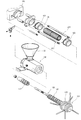
도 8은 본 고안에 따른 착유기본체에 장착되는 이송스크류 및 착유스크류가 구비된 구동축을 보여주는 도면.8 is a view showing a drive shaft provided with a transfer screw and a milking screw mounted to the milking base according to the present invention.
* 도면의 주요부분에 대한 부호의 설명 *Explanation of symbols on the main parts of the drawings
1 : 착유기본체 10 : 건조부1
11,21 : 히팅체 20 : 착유부11,21: heating body 20: milking part
22 : 격자조립체 25 : 장축22: lattice assembly 25: long axis
30 : 호퍼조립체 31 : 호퍼30: Hopper assembly 31: Hopper
40 : 구동부 50 : 구동축40: drive unit 50: drive shaft
51 : 이송스크류 52 : 착유스크류51: transfer screw 52: milking screw
60 : 제어부 70 : 기름통 60: control unit 70: oil drum
본 고안은 깨분용 연속식 자동 착유기에 관한 것으로, 보다 상세하게는 스크류 압착 방식을 갖는 착유기본체에서 건조부와 착유부를 구분하여 순차적으로 배치함으로써, 깨분과 같은 착유물에서 착유하고자 할 때, 착유기본체의 건조부에서 깨분을 먼저 건조(혹은 볶음)한 다음, 스크류 이송 방식을 통해 연속적으로 스크류 압착하여 착유부에서 착유함에 따라 호퍼 내에 공급되는 깨분을 별도의 볶음기를 통해 다시 볶지 않고 투입하더라도 종래 압착식 착유기에 비해 상대적으로 착유 효율을 향상시킬 수 있음은 물론, 별도의 건조부를 갖는 착유기 자체의 구조를 간소화 시킬 수 있고, 착유기의 조작이 용이하여 깨분 형태의 곡물을 착유하는 데 있어 인력과 시간을 절약할 수 있는 깨분용 연속식 자동 착유기에 관한 것이다.The present invention relates to a continuous automatic milking machine for sesame powder, and more specifically, to milk in a milking material, such as sesame powder by sequentially arranging the milking part and the drying part in the milking base body having a screw crimping method. Drying (or roasting) the sesame powder in the drying part of the first, and then screw-squeezed continuously through the screw feed method, so that the milk powder supplied in the hopper is fed into the hopper without being roasted again through a separate roaster as it is milked in the milking part. Compared to the milking machine, the milking efficiency can be improved, and the structure of the milking machine itself having a separate drying unit can be simplified, and the milking machine can be easily operated, which saves manpower and time in milking grain-shaped grains. The present invention relates to a continuous automatic milking machine for grinding.
주지하는 바와 같이 착유기는 참깨, 들깨 등과 같은 각종 곡물과 그 곡물의 가루분들을 압착하여 식용 기름을 짜내는 것으로서, 종래 유압을 이용한 압착방식 의 착유기가 널리 이용되고 있었다.As is well known, the milking machine is to squeeze edible oil by squeezing various grains such as sesame and perilla and powdered powder of the grains, and a conventional milking machine using a hydraulic method has been widely used.
즉, 상기 압착식 착유기는 기본적으로 본체 상판에 곡물을 투입되는 호퍼가 구비되고, 그 저면에는 가압판이 구비되며, 본체 하판에는 곡물의 기름을 배출하는 착유통과, 상기 착유통 내의 하부에 실린더가 구비되는 것을 기본 구조로 가지고 있고, 이와 같은 구조에서 상기 착유통 내에 곡물을 넣고 그 하부의 실린더가 가압판으로 강하게 승강되면서 그 압박력에 의해 기름이 짜여지도록 되어 있다.That is, the pressurized milking machine is basically provided with a hopper for introducing grain into the upper body plate, the bottom surface is provided with a pressure plate, the lower body of the main body is provided with a milking barrel for discharging the oil of the grain, the cylinder in the lower portion of the milking container It has a basic structure, and in such a structure, the grain is put into the milk container and the lower cylinder is raised and lowered strongly by the pressure plate, so that the oil is squeezed by the pressing force.
이때, 투입되는 곡물들은 기름이 잘 짜여지도록 별도의 볶음기를 통해 일정시간 볶아서 투입하게 되며, 착유 시에는 곡물의 열이 식기 전에 빠르게 곡물을 압박하여 기름을 착유하도록 되어 있었다.At this time, the input grains are roasted for a predetermined time through a separate stir fryer so that the oil is well woven, and during milking, the grains were milked by pressing the grains quickly before the heat was cooled.
따라서, 종래의 압착식 착유기는 단순히 가압력만으로 기름을 착유하기 때문에 곡물의 열이 식기 전에 빠르게 작업을 수행해야 하며, 한편 시간을 지체하여 곡물이 식어버리게 되면 딱딱해져서 기름이 잘 짜여지지 않는 문제점이 있었다.Therefore, the conventional pressurized milking machine needs to perform the operation quickly before the heat of the grains cools down because the milking machine simply milks the pressing force. On the other hand, when the grains cool down due to a delay, the oil becomes hard to squeeze well. .
이에 따라 최근에 기계의 자동화와 착유율을 향상시키기 위하여 상기 유압을 이용한 압착방식이 아닌 스크류 가압 방식을 통해 이송 압착하여 착유하는 착유기가 개발 제시되었다.Accordingly, in recent years, in order to improve the automation and milking rate of the machine, a milking machine for feeding and compressing milking through a screw pressurization method, rather than the crimping method using the hydraulic pressure, has been developed.
즉, 근래 출원되어 특허 등록된 등록특허 제0173548호(1998. 10.30. 등록) 및 등록실용신안 제0183012호 (2000.3.11. 등록)에 각각 개시된 "착유기"는 통상의 동력절단부에서 발생하는 동력을 착유부본체에 전달하여 이송스크류 및 착유스크류를 가동시킴으로써, 착유가 이루어지도록 하는 스크류 가압 방식을 적용한 것이다.That is, the "milking machine" disclosed in recently registered patent application No. 0173548 (registered on Oct. 30, 1998) and Utility Model No. 0183012 (registered on March 31, 2000), respectively, is used to generate power generated by a normal power cutting unit. By applying a screw pressurizing method so that milking is achieved by transferring the milking unit to the milking unit and operating the feeding screw and the milking screw.
여기서, 상기 등록특허 제0173548호에 개시된 착유기는 모터의 회전력이 구 동축을 통해 이송 스크류와 착유 스크류로 전달되는 과정에서 발생되는 구동축의 비틀림 및 진동을 최소화하여 결합강도를 증대시킴과 동시에, 청소 및 부품의 교체시에 이송 스크류와 착유 스크류를 착유부본체로부터 용이하게 분해 결합할 수 있도록 함과 동시에, 미세한 기름배출로가 형성된 격자체를 제공하여 유박입자의 혼입을 막고 기름만 배출되도록 하여 청결한 기름을 얻을 수 있는 구조를 지닌다.Here, the milking machine disclosed in Korean Patent No. 0173548 minimizes the torsion and vibration of the drive shaft generated in the process in which the rotational force of the motor is transmitted to the feed screw and the milking screw through the drive shaft, thereby increasing the coupling strength, and cleaning and When replacing parts, the feed screw and the milking screw can be easily disassembled and combined from the milking unit body, while providing a lattice with a fine oil drainage path to prevent the mixing of oil particles and to discharge only the oil. It has a structure that can be obtained.
그리고, 상기 등록실용신안 제0183012호에 개시된 스크류 가압 방식의 착유기는, 도 1 내지 도 3에 도시된 바와 같이, 상부의 각종 기구들을 지지하는 본체(100)와, 본체(100)의 일측에 부착되며 모터 및 각종 구동기어가 내장되어 있는 구동부(120)와, 이 구동부(120)의 일측에 부착되는 제어부(140)와, 상기 구동부(120)로부터 전달되는 동력에 의해서 회전되는 샤프트 바(150)와, 상기 샤프트 바(150)의 외주면에 장착되는 이송 스크류(160) 및 착유 스크류(170)와, 장축(230)을 개재하여 상기 구동부(120)에 고정되면서 참깨나 들깨 등의 착유물을 집어넣는 호퍼(132)가 구비되어 있는 호퍼 조립체(130)와, 내부에 회전 가능하게 장착되어 있는 상기 착유스크류(170)에 의해 만들어진 기름을 배출하기 위한 격자 조립체(180)와, 상기 격자 조립체(180)의 외주부에 장착되는 히터(190)와, 상기 격자 조립체(120)로부터 배출된 기름을 분기관을 개재하여 2개의 기름통(110)으로 안내하는 기름 안내레일(220) 및 호퍼 조립체(130)의 일측에 체결되어 있는 제 1 및 제 2핸들 조립체(200, 210)로 이루어져 있다. And, the screw pressurized milking machine disclosed in the Utility Model No. 0183012, as shown in Figures 1 to 3, the
그리고, 상기 격자 조립체(120)로부터 길이 방향을 따라 이송된 깻묵을 절개하여 분쇄되도록 하는 깻묵 분쇄수단과, 모터를 역회전시켜 상기 호퍼 조립체(130) 내에 들어있는 이물질을 배출시키기 위한 이물질 배출수단을 포함하고 있다.And, by cutting the ink conveyed in the longitudinal direction from the
이와 같은 구성을 갖는 상기한 등록실용신안 제0183012호에 개시된 스크류 가압 방식의 착유기는, 통깨와 같은 곡물을 별도의 볶음기를 통해 1차적으로 볶은 다음, 상기 호퍼 조립체(130) 상의 호퍼(132) 내에 넣은 후, 제어부(140) 조작을 통해 상기 구동부(120)를 구동시킴으로써, 상기 구동부(120)에 연결된 샤프트 바(150)의 회전에 따라 이송 스크류(160) 및 착유 스크류(170)의 이송 및 압착 작용이 일어나 격자 조립체(180) 내부에서 착유가 이루어지게 되고, 기름은 격자 조립체(180)에 형성된 기름 배출로를 통해서 기름 안내레일(220)로 배출되는 것이다.The screw pressurized milking machine disclosed in the above-described utility model No. 0183012, which has such a configuration, first roasts grains such as sesame seeds through a separate roaster, and then hoppers 132 on the
이때, 상기 격자 조립체(180)의 외주부에 장착된 히터(190)는 1차적으로 볶아서 공급되는 착유물이 착유과정에서 식지않도록 일정한 온도로 가열하는 기능을 수행하게 되는 것이다.At this time, the
그러나, 상기와 같은 등록실용신안 제0183012호에 개시된 스크류 가압 방식의 착유기는, 주로 통깨와 같은 곡물을 별도의 볶음기를 통해 1차적으로 볶아서 공급하는 구조를 가지고 있어 별도의 볶음기를 필요로 할 뿐만 아니라 별도의 볶음 작업 공정을 거쳐야 하기 때문에 작업의 번거로움이 있었다.However, the screw pressurized milking machine disclosed in the above-mentioned Utility Model No. 0183012 has a structure in which the grains such as sesame seeds are primarily roasted and supplied through a separate roaster, and thus, a separate roaster is required. The work was cumbersome because it had to go through a separate roasting process.
그런데, 최근에 참깨나 들깨와 같은 착유물을 착유하는 과정에서 통깨 형태로 착유하는 것이 아니라 통깨를 갈아서 볶은 깨분 형태로 착유해야만 하는 경우가 발생하고 있다.However, recently, in the process of milking a milking material such as sesame or perilla, it is necessary to milk the sesame powder in the form of roasted sesame powder instead of milking in the form of sesame seeds.
즉, 최근 중국이나 인도와 같은 외국에서 참깨, 들깨와 같은 곡물을 수입해 오는 과정에서 통관상의 절차나 곡물의 부피와 같은 기타 이유로 인해 통깨를 갈아 서 볶은 깨분 형태로 수입되고 있어 깨분 형태로 착유해야만 하는 실정인 것이다.In other words, in the process of importing grains such as sesame and perilla from foreign countries such as China and India, they are imported in the form of roasted sesame powder, ground for sesame powder due to customs procedures or other reasons such as grain volume. It is the situation.
이에 따라, 상기 등록실용신안 제0183012호에 개시된 스크류 가압 방식의 착유기의 경우에는 깨분 형태의 착유물을 착유하는 데 구조적으로 어려움이 있었다.Accordingly, in the case of the screw pressurized milking machine disclosed in the Utility Model No. 0183012, there is a structural difficulty in milking the milk powder in the form of powder.
즉, 상기 깨분의 경우, 1차적으로 통깨를 갈아서 볶은 상태로 수입되고 있기 때문에 착유을 위해 별도의 볶음기를 통해 다시 한번 볶을 경우에는 기름의 산화나 이물질 혼입에 따라 착유된 기름의 품질에 문제가 발생할 수 있었다.That is, in the case of the sesame powder, since the sesame seeds are first imported in a state of roasting, when roasted once again through a separate stir for milking, a problem may occur in the quality of the milked milk due to the oxidation of the oil or the mixing of foreign substances. there was.
그럼으로, 별도의 볶음 과정없이 착유과정에서 열을 가해 건조(볶음)과정을 거친 후 착유하는 것이 바람직하나, 상기한 등록특허 제0173548호 및 등록실용신안 제0183012호 등에 개시된 착유기는 별도로 깨분을 건조할 수 있는 구조를 갖추고 있지 않기 때문에 깨분 형태의 착유물을 착유하는 데 어려움이 있는 것이다.Therefore, it is preferable to milk after the drying (roasting) process by applying heat in the milking process without a separate roasting process, but the milking machine disclosed in the above-described Patent Registration No. 0173548 and Utility Model No. 0183012 separately dry the sesame powder. It does not have the structure to do so it is difficult to milk powder in the form of powder.
물론, 등록특허 제0173548호 및 등록실용신안 제0183012호 등에 개시된 착유기에도 착유 과정에서 열을 가하기 위한 히터가 상기 격자 조립체의 외주부에 마련되어 있으나, 상기 히터의 경우에는 별도의 건조(볶음)기능을 수행하기 보다는 실질적으로 1차적으로 볶아서 공급되는 통깨 형태의 착유물이 착유과정에서 식지 않도록 하여 착유율이 향상되도록 하는 데 불과한 것이다.Of course, a heater for applying heat in the milking process is also provided on the outer periphery of the lattice assembly in the milking machine disclosed in Korean Patent No. 0173548 and Utility Model No. 0183012, but the heater performs a separate drying (roasting) function. Rather, it is only to improve the milking rate by preventing the milking in the form of sesame, which is supplied by roasting substantially in the milking process.
즉, 상기한 착유기는 건조과정과 착유과정이 분리된 것이 아니라 착유가 이루어지면서 단순히 히터에 의해 열이 가해지는 것에 불과하기 때문에 깨분과 같이 이미 1차적으로 볶아져서 수입되는 곡물을 상기한 착유기를 통해 착유하는 것은 바람직하지 못하다는 문제점이 있었다.In other words, the milking machine is not separated from the drying process and the milking process, but simply because heat is applied by the heater as milking takes place, such as sesame powder, which is already primarily roasted and imported through the milking machine. There was a problem that milking is undesirable.
이에 본 고안은 상기와 같은 종래 개시된 스크류 압착 방식을 갖는 착유기가 깨분 형태의 곡물을 착유하는 데 어려움이 있다는 점을 감안하여 깨분 형태의 착유물을 보다 효율적으로 착유할 수 있는 새로운 타입의 깨분 전용 착유기를 제공하고자 안출된 것이다.The present invention is a new type of milk powder dedicated milking machine which can milk the powdered milk powder in a more efficient manner in view of the difficulty in milking the powder of the cereal powder in the milking machine having the conventional screw compression method as described above. It is intended to provide.
즉, 본 고안의 목적은 스크류 압착 방식을 갖는 착유기본체에서 건조부와 착유부를 구분하여 순차적으로 배치함으로써, 깨분과 같은 착유물에서 착유하고자 할 때, 착유기본체의 건조부에서 깨분을 먼저 건조(혹은 볶음)한 다음, 스크류 이송 방식을 통해 연속적으로 스크류 압착하여 착유부에서 착유함에 따라 호퍼 내에 공급되는 깨분을 별도의 볶음기를 통해 다시 볶지 않고 투입하더라도 종래 압착식 착유기에 비해 상대적으로 착유 효율을 향상시킬 수 있음은 물론, 별도의 건조부를 갖는 착유기 자체의 구조를 간소화 시킬 수 있고, 착유기의 조작이 용이하여 깨분 형태의 곡물을 착유하는 데 있어 인력과 시간을 절약할 수 있는 깨분용 연속식 자동 착유기를 제공하는 데 있다.That is, an object of the present invention is to dry the sesame powder first in the drying part of the milking body when milking from the milking material such as sesame powder by sequentially placing the drying part and the milking part in the milking base body having a screw crimping method. Roasting), and then screwed continuously through the screw feed method to improve the milking efficiency relative to the conventional pressurized milking machine even if the sesame powder supplied into the hopper without being roasted again through a separate roaster as milking in the milking unit Of course, it is possible to simplify the structure of the milking machine itself having a separate drying unit, and the continuous automatic milking machine for sesame powder that can save manpower and time in milking the grain-type grains easy to operate the milking machine To provide.
상기와 같은 목적을 달성하기 위한 본 고안은 동력을 전달하는 구동부와, 이 구동부의 일측에 부착되는 제어부를 갖추고, 착유물을 집어넣는 호퍼가 구비되어 있는 호퍼조립체와, 상기 호퍼조립체에 연계하여 수평하게 배치되는 착유기본체를 갖추며, 상기 착유기본체 내에 구동부로부터 전달되는 동력에 의해서 회전되는 구동축과, 상기 구동축의 외주면에 장착되는 이송스크류 및 착유스크류를 갖춤으로써, 착유물을 스크류 이송 방식을 통해 연속적으로 스크류 압착하여 착유하도록 된 착유기에 있어서, 상기 착유기본체가 이송스크류가 배치되는 건조부와 착유스크류가 배치되는 착유부로 구분되어 상기 구동부와 호퍼조립체에 장축을 매개로 연결배치되되; 상기 건조부는 원통형의 히팅체가 수평 길이방향으로 상기 호퍼조립체로부터 순차적으로 복수개 배치된 구조를 갖고, 각각의 히팅체 사이에는 히팅체를 상호 긴밀하게 고정시켜 되는 고정체가 매개되어 장착되는 구조를 갖고; 상기 착유부는 착유스크류에 의해 착유된 기름을 배출하기 위한 원통형의 격자조립체가 구비되고, 상기 격자조립체의 외주면에 히팅체가 장착되는 구조를 갖는 것을 특징으로 하는 깨분용 연속식 자동 착유기를 제공함으로써 달성된다.The present invention for achieving the above object is a hopper assembly having a drive unit for transmitting power, and a control unit attached to one side of the drive unit, the hopper assembly is provided with a hopper to put the milking object, and horizontally connected to the hopper assembly It is equipped with a milking main body is arranged to be, and the drive shaft rotated by the power transmitted from the driving unit in the milking base body, and a feed screw and a milking screw mounted on the outer peripheral surface of the drive shaft, the milking material continuously through a screw feed method In the milking machine to be screwed and milked, the milking main body is divided into a drying unit in which the transfer screw is disposed and the milking unit in which the milking screw is arranged is connected to the drive unit and the hopper assembly via a long axis; The drying unit has a structure in which a plurality of cylindrical heating bodies are sequentially arranged from the hopper assembly in a horizontal length direction, and each of the heating bodies has a structure in which a fixing body for tightly fixing the heating bodies is mediated therebetween. The milking unit is achieved by providing a cylindrical grid assembly for discharging oil milked by the milking screw, and having a structure in which a heating body is mounted on the outer circumferential surface of the grid assembly. .
이때, 상기 구동축 상에 구비된 상기 이송스크류와 착유스크류에 각각 연속적으로 형성된 스크류의 리이드 길이가 상기 건조부의 초기 시점인 이송스크류의 최초 리이드 길이로부터 착유스크류가 끝나는 최끝단 리이드 길이로 갈수록 점점 줄어드는 가변형 리이드 길이로 제작되는 것이 바람직하다.At this time, the lead length of the screw continuously formed on the transfer screw and the milking screw provided on the drive shaft is gradually reduced from the initial lead length of the transfer screw, which is the initial time of the drying unit, to the end length of the end of the milking screw. It is preferred to be produced with a lead length.
이하 상기와 같은 본 고안의 바람직한 실시예를 첨부도면에 의거하여 상세히 설명하면 다음과 같다.Hereinafter, a preferred embodiment of the present invention as described above in detail based on the accompanying drawings.
도 4는 본 고안에 따른 깨분용 연속식 자동 착유기를 보여주는 사시도이고, 도 5는 본 고안에 따른 깨분용 연속식 자동 착유기의 구성을 개략적으로 보여주는 정면도이며, 도 6은 본 고안에 따른 깨분용 연속식 자동 착유기의 요부인 착유기본체를 보여주는 사시도 이고, 도 7은 본 고안에 따른 도 6에 도시된 착유기본체를 정면에서 바라본 정면도이며, 도 8은 본 고안에 따른 착유기본체에 장착되는 이송 스크류 및 착유스크류가 구비된 구동축을 보여주는 도면이다.Figure 4 is a perspective view showing a continuous automatic milking machine for sesame powder according to the present invention, Figure 5 is a front view schematically showing the configuration of the continuous automatic milking machine for sesame powder according to the present invention, Figure 6 is a continuous powder for sesame powder according to the present invention Figure 7 is a perspective view showing a milking main body which is a main part of an automatic milking machine, and FIG. 7 is a front view of the milking main body shown in FIG. 6 according to the present invention, and FIG. 8 is a feed screw and milking mounted on the milking base according to the present invention. The figure shows a drive shaft with a screw.
도 4 및 도 5에 도시된 바와 같이, 본 고안에 따른 착유기는 상부의 각종 기구들을 지지하는 지지체(90)와, 상기 지지체(90)의 일측에 부착되며 모터 및 각종 구동기어가 내장되어 있는 구동부(40)와, 이 구동부(40)의 일측에 부착되는 제어부(60)를 갖추고 있다.As shown in Figures 4 and 5, the milking machine according to the present invention is a
상기 제어부(60)는 구동부(40)에 마련된 구동모터(도시안됨)의 회전속도 조절에 따른 후술하는 이송 및 착유스크류(51,52)의 회전속도를 조절하여 착유물의 종류(주로 깨분)에 따라 적절한 착유가 이루어질 수 있도록 함은 물론, 후술하는 각 히팅체(11,21)의 온도조절과, 구동모터의 온/오프(on/off)스위치, 착유기의 정상 작동유무를 확인할 수 있는 램프 등이 설치되어 있어 착유기의 각종 기능을 작업자가 제어할 수 있도록 되어 있다.The
그리고, 본 고안의 착유기에는 참깨나 들깨 등을 갈아서 볶은 깨분 형태의 착유물을 집어넣는 호퍼(31)가 구비되어 있는 호퍼 조립체(30)와, 상기 호퍼 조립체(30)에 연계하여 수평하게 배치되는 착유기본체(1)를 갖추고 있다.In addition, the milking machine of the present invention is provided with a
여기서, 상기 착유기본체(1)는, 도 6 및 도 7에 도시된 바와 같이, 상기 호퍼(31)를 통해 공급되는 착유물을 스크류 방식으로 이송하면서 압착하여 착유하는 기능을 수행하는 부분으로써, 본 고안은 상기 착유기본체(1)가 건조부(10)와 착유부(20)로 구분 배치되어 있다는 데 그 특징을 갖는다..Here, the milking
즉, 상기 건조부(10)는 깨분을 건조시키는 역할을 하는 곳으로, 원통형의 히팅체(11)가 수평 길이방향으로 상기 호퍼 조립체(30)로부터 순차적으로 복수개 배 치된 구조를 갖으며, 각각의 히팅체(11) 사이에는 히팅체(11)를 상호 긴밀하게 고정시켜 되는 원통형의 고정체(12)가 매개되어 장착되어 있다.That is, the drying
이때, 상기 건조부(10)의 히팅체(11)는 깨분 형태의 착유물을 건조(혹은 볶음)하기 위해 250℃ 이상의 고열을 발생할 수 있다.In this case, the
그리고, 상기 건조부(10)의 후방에는 착유부(20)가 연속적으로 연결 배치되어 있는 바, 상기 착유부(20)는 건조부(10)를 통해 건조되어 이송된 깨분 형태의 착유물을 점진적으로 압착하여 착유하는 부위로써, 상기 착유부(20)에는 후술하는 착유스크류(52)에 의해 착유된 기름을 배출하기 위한 원통형의 격자 조립체(22)가 구비되어 있고, 상기 격자 조립체(22)의 외주면에는 상기 건조부의 히팅체(11)와 유사한 별도의 히팅체(21)가 장착되어 있다.In addition, the milking
여기서, 상기 기름을 배출하는 통로 역할을 하는 격자조립체(22)는 구체적으로 도시되지 않았지만, 등록특허 제0173548호 등에 이미 개시된 바와 같이 사각형의 격자와 육각형의 격자를 순차적으로 배치시켜 긴밀한 지지력을 갖도록 한 구조를 갖는 것으로 여기서는 그 구체적인 구조에 대해서는 생략하도록 한다.Here, although the
다만, 상기 격자조립체(22)를 구성하는 사각형의 격자와 육각형의 격자가 접촉되는 후방부의 접촉면에는 미세한 홈을 가공하여 기름 배출로(도시안됨)가 형성되어 있고, 사각형의 격자와 육각형의 격자가 접촉하는 접촉부의 내면에 상기 기름배출로와 동일 작용을 하게 되는 기름유도로를 형성되어 있다.However, an oil discharge path (not shown) is formed on the contact surface of the rear portion where the rectangular grid and the hexagonal grid, which form the
그리고, 상기 착유부(20)의 히팅체(21)는 착유과정에서 건조부(10)에서 고열을 받은 착유물이 일정 정도 식지않도록 하여 착유율을 높이고자 하는 목적을 가지 고 있는 것으로, 건조부(10)의 히팅체(11)에 비해 상대적으로 낮은 열을 제공해도 무방하다.In addition, the
또한, 상기 건조부(10)의 히팅체(11) 및 착유부(20)의 히팅체(21)는 각각의 전열선(26)이 제어부(60)에 연결되어 있기 때문에 제어부(60)를 통해 선택적으로 온도를 조절 제어할 수 있다.In addition, the
한편, 상기와 같이 건조부(10)와 착유부(20)로 구분된 착유기본체(1)의 장착과정을 보다 상세하게 살펴보면, 상기 건조부(10)와 착유부(20)가 구분 배치되어 있는 상기 착유기본체(1)는 상기 구동부(40)의 선단부와 호퍼조립체(30)의 플랜지부(33) 사이에 2개의 장축(25)을 이용하여 설치되게 된다.On the other hand, look at the mounting process of the milking base (1) divided into the drying
즉, 상기 착유기본체(1)의 일측을 담당하는 상기 착유부(20)는 상기 구동부(40)의 선단부 쪽에 근접하여 배치되고, 그 반대쪽인 건조부(10)는 상기 호퍼조립체(30)에 연결 배치된다.That is, the milking
이때, 상기 착유부(20)는 구동부(40)의 선단부 쪽에 부싱을 이용하여 상기 격자조립체(22)를 지지하기 위한 격자체설치구(23)를 통해 지지 고정되어 있고, 상기 건조부(10)와 착유부(20) 사이에도 착유부(20)의 격자조립체(22)와 건조부(10)의 히팅체(11)을 상호 연결 지지함과 동시에 상기 구동부(40)의 선단부와 호퍼조립체(30)의 플랜지부(33) 사이에 설치된 장축(25)을 지지할 수 있는 격자체설치구(24)가 마련되어 있으며, 상기 건조부(10)의 일단은 호퍼 조립체(30)에 연결됨으로써 착유기본체(1)가 착유기에 장착되게 된다.In this case, the milking
이렇게 장착된 본 고안에 따른 착유기본체(1)는 착유 후 착유기본체(1)를 분해하고자 할 때, 전후방에 위치되어 고정 설치된 장축(25)의 선단부 즉, 호퍼조립체(30)의 플랜지부(33)의 구동부(40) 후방부와 너트에 의해서 고정 설치된 것을 풀고 장축(25)를 양측으로 벌리면, 착유기본체(1)는 자동으로 분리되게 되고, 그 후 착유기본체(1)의 각 구성품들을 순차적으로 분리하면 된다.When the milking
한편, 상기 착유기본체(1)에는 도 8에 도시된 바와 같은 상기 구동부(40)로부터 전달되는 동력에 의해서 회전되는 구동축(50)이 관통 배치되고, 상기 구동축(50)의 외주면에는 착유물을 이송 및 압착하는 이송 스크류(51) 및 착유 스크류(52)가 장착되며, 상기 구동축(50)의 일단에는 구동축(50)의 길이방향 이동을 통해 유격을 조절 및 고정할 수 있는 제 1 및 제 2핸들 조립체(53,54)가 조립되어 있다.On the other hand, the milking
즉, 상기 호퍼조립체(30)의 중앙에는 이송스크류(51)가 수용되도록 관통공이 형성되어 있고, 이 관통공에는 이송스크류(51)를 긴밀히 삽입하여 위치시킴과 동시에 구동축(50)와 일단에 일체로 형성된 제 1 및 제 2핸들 조립체(53,54)가 조립되도록 되어 있다.That is, a through hole is formed in the center of the
그리고, 상기 제 1 및 제 2핸들 조립체(53,54)에는 전후방에 각각의 구체적으로 도시되지 않은 조임구를 구비시켜 구동축(50) 및 이송스크류(51)를 호퍼조립체(30)의 선단부에 견고히 고정시키도록 되어 있다.In addition, the first and
이때, 상기 이송스크류(51)와 착유스크류(52)의 구분은 상기 건조부(10)와 착유부(20)의 구분에 따라 임의로 구분하고 있는 것으로, 구동축(50) 상에 서로 연속적인 리이드를 갖는 스크류 형태로 제작되게 된다.At this time, the
즉, 상기 이송 스크류(51)는 호퍼(31)를 통해 깨분 형태의 착유물이 공급될 때 이를 건조부(10)에서 건조시키면서 후방으로 압착 이송시키는 역할을 하는 부위이고, 상기 착유스크류(52)는 착유부(20) 내의 스크류를 일컫는 것으로써, 이송스크류(51)를 통해 이송된 착유물을 압착하여 착유하는 역할을 수행하는 스크류 부위이다.That is, the conveying
특히, 본 고안에 따른 상기 이송스크류(51)와 착유스크류(52)는 점진적으로 스크류의 리이드 길이가 짧아지는 가변 리이드를 갖도록 제작되어 있다.In particular, the
즉, 상기 건조부(10)의 초기시점인 이송스크류(51)의 최초 리이드 길이(L1)로부터 착유스크류(52)가 끝나는 최끝단 리이드 길이(L2)로 갈수록 스크류의 리이드 길이가 점점 줄어드는 가변형 리이드를 갖도록 스크류가 제작되어 있다.That is, the variable lead of the lead length of the screw gradually decreases from the initial lead length L1 of the
이처럼 가변형 리이드를 갖도록 이송스크류(51)와 착유스크류(52)를 제작하는 이유는 이송스크류(51)에서는 충분한 리이드 길이를 확보하여 원활한 이송이 이루어짐과 동시에 충분한 건조가 일어날 수 있도록 착유스크류(52) 쪽에 비해 상대적으로 리이드 길이를 길게 형성한 것이고, 착유스크류(52) 쪽으로 갈수록 점차적으로 리이드 길이를 짧게 하여 착유물이 이송 압착되는 과정에서 좀 더 착유물의 압착밀도를 높혀 줌으로써, 착유율을 향상시키고자 함이다.The reason for manufacturing the
이때, 상기 이송스크류(51) 및 착유스크류(52)에서 가변되는 각각의 스크류의 리이드 길이는 몇 개의 스크류를 하나의 단위로 묶어서 묶여진 스크류 단위별로 리이드 길이를 가변시킬 수 도 있는 바, 이때에도 역시 이송스크류(51)쪽에서 착유스크류(52)쪽으로 점진적으로 줄어드는 리이드 길이를 부여하게 됨은 당연하다.At this time, the lead length of each screw that is variable in the conveying
이와 같은 이유에서 도 8에 도시된 바와 같이 전체적으로 건조부(10)의 길이가 착유부(20)의 길이보다 상대적으로 길게 형성 배치하는 것이 바람직하다.For this reason, as shown in FIG. 8, it is preferable that the length of the drying
또한, 도면에 자세히 도시하지는 않았지만 상기한 이송스크류(51)의 선단부에는 이송스크류(51) 방향과 동일한 방향으로 회전하는 강질의 착유스크류(52)를 부분적으로 이송스크류(51)가 설치된 구동축(50) 상에 분리 삽입하고 후단부를 너트로 긴밀히 고정시키는 구조를 취하고 있다.In addition, although not shown in detail in the drawing, the
이처럼 상기 이송스크류(51)와 착유스크류(52)의 일부를 분리할 수 있도록 한 이유는 착유스크류(52)측에 부하가 많이 발생함은 물론 그에 따른 마모가 심하여 착유 스크류(52)의 훼손이 쉽게 이루어짐으로 훼손된 착유스크류(52)만 용이하게 교체 사용할 수 있도록 하기 위함으로, 이러한 기술 역시 공지된 선행기술임을 밝힌다.As such, the reason why the part of the
한편, 상기 착유기본체(1)의 하부에는 상기 착유부(20)의 격자 조립체(22)로부터 배출된 기름을 받아내기 위해 넓은 판상의 기름받이판(80)와 기름받이판을 따라 흘러내린 기름을 2개의 기름통(70)으로 안내하는 기름 안내레일(81) 구비되어 있다.On the other hand, the lower portion of the milking base (1) is the oil flowing down along the wide plate of the
이상과 같은 구성적 특징을 갖는 본 고안에 따른 착유기의 작용효과를 상세히 설명하면 다음과 같다.Referring to the effect of the milking machine according to the present invention having the above configuration features in detail as follows.
본 고안에 따른 착유기를 통해 깨분 형태의 착유물에서 착유하고자 할 경우에는, 먼저 호퍼(31)에 착유하고자 하는 목적물 즉, 깨분 형태의 착유물을 별도의 볶음기를 통해 볶지 않은 상태로 그대로 투입한 후 구동부(40)내에 설치된 구동모 터를 작동시키면, 도시되지 않은 구동모터는 착유스크류(52)와 이송스크류(51)가 삽입 설치된 구동축(50)를 회전시키게 되는 것이다.In the case of milking in the form of sesame powder through the milking machine according to the present invention, the first object to be milked in the
이와 같이 하여 구동축(50)이 회전을 하게 되면 상기 착유스크류(52)와 이송스크류(51)가 동시에 회전을 하면서 호퍼(31)에 장입된 착유물을 순차적으로 이송스크류(51)에서 착유스크류(52) 쪽으로 이송을 시키게 된다.When the
이때, 상기 건조부(10)의 히팅체(11)가 작동하여 이송스크류(51)를 통해 건조부(10)를 거쳐 이송되는 착유물이 건조됨과 동시에 점진적으로 가변되는 스크류의 리이드 길이 변화에 맞춰 착유물의 압착정도 강화되면서 착유물의 밀도가 높아지면서 착유스크류(52) 쪽으로 이송되게 된다.At this time, the
상기와 같이 하여 착유물이 착유스크류(52)로 이송되게 되면, 착유스크류(52)는에서 더욱더 착유물의 밀도를 높여 줌으로써, 격자조립체(22)내에서 착유물에 강한 압착력을 가하여 착유를 하게 되는 것이다.When the milking material is transferred to the milking
한편, 착유된 기름은 격자조립체(22)에 구비된 기름유도로를 따라 후방 즉, 착유스크류(52)의 진행방향에 따라 진행하면서 기름 배출로로 배출되어 기름받이판(80) 및 기름 안내레일(81)를 통해 기름통(70)로 수용되게 되는 것이다.On the other hand, the milked oil is discharged to the oil discharge path while traveling along the oil flow path provided in the
그리고, 착유가 되고 남은 유박은 착유스크류(52)의 후방을 통해 착유기본체(1)로부터 외부로 배출되거나 착유기본체(1) 내에 남은 유박은 별도의 청소 작업을 통해 제거되게 되는 것이다.Then, the milk foil remaining after milking is discharged from the milking
이처럼, 본 고안은 착유기본체(1) 상에 건조부(10)와 착유부(20)를 각각 구분하여 배치하고, 상기 건조부(10)를 착유부(20)와 달리 격자조립체(22)를 갖지않 으면서 히팅체로만 이루어진 별도의 구조로 구성함으로써, 보다 효율적으로 깨분 형태의 착유물을 건조시킬 수 있도록 하고 있으며, 특히 깨분을 별도의 볶음기로 다시 한번 볶지 않은 상태에서 호퍼(31)에 투입하여도 건조부(10)의 히팅체(11)에서 발생하는 열에 의하여 건조과정을 거칠 수 있는 것이다.As such, the present invention separates and arranges the drying
또한, 착유과정에서도 착유부(20)의 격자조립체(22) 외주면에 설치되는 또 다른 히팅체(21)를 통해 열을 가해 건조부(10)에서 열을 받아 건조된 착유물이 식지않도록 함으로써, 공지된 종래의 기술과 마찬가지로 착유율을 높일 수 있는 장점을 갖는 것이다.In addition, in the milking process, by applying heat through another
이상에서 살펴본 바와 같이 본 고안에 따르면, 스크류 압착 방식을 갖는 착유기본체에서 건조부와 착유부를 구분하여 순차적으로 배치함으로써, 깨분과 같은 착유물에서 착유하고자 할 때, 착유기본체의 건조부에서 깨분을 먼저 건조(혹은 볶음)한 다음, 스크류 이송 방식을 통해 연속적으로 스크류 압착하여 착유부에서 착유함에 따라 호퍼 내에 공급되는 깨분을 별도의 볶음기를 통해 다시 볶지 않고 투입하더라도 종래 압착식 착유기에 비해 상대적으로 착유 효율을 향상시킬 수 있는 효과가 있다.As described above, according to the present invention, when the milking body having a screw crimping method is arranged in a sequential manner by separately separating the drying part and the milking part, when milking from an milking material such as sesame powder, the powdered flour in the drying part of the milking body first Drying (or roasting), and then screwed continuously through the screw transfer method to milk in the milking unit, even if the sesame powder supplied in the hopper is not roasted again through a separate roaster, the milking efficiency is relatively higher than that of the conventional crimping machine. There is an effect to improve.
또한 본 고안은 별도의 건조부를 갖는 착유기 자체의 구조를 간소화 시킬 수 있고, 착유기의 조작이 용이하여 깨분 형태의 곡물을 착유하는 데 있어 인력과 시간을 절약할 수 있는 깨분용 연속식 자동 착유기를 제공할 수 있다.In addition, the present invention can simplify the structure of the milking machine itself having a separate drying unit, it is easy to operate the milking machine to provide a continuous automatic milking machine for sesame powder that can save manpower and time in milking the grain-shaped grain can do.
Claims (2)
Priority Applications (1)
| Application Number | Priority Date | Filing Date | Title |
|---|---|---|---|
| KR2020070005074U KR200440244Y1 (en) | 2007-03-28 | 2007-03-28 | Continue Type Automatic Expeller |
Applications Claiming Priority (1)
| Application Number | Priority Date | Filing Date | Title |
|---|---|---|---|
| KR2020070005074U KR200440244Y1 (en) | 2007-03-28 | 2007-03-28 | Continue Type Automatic Expeller |
Publications (1)
| Publication Number | Publication Date |
|---|---|
| KR200440244Y1 true KR200440244Y1 (en) | 2008-06-02 |
Family
ID=41639077
Family Applications (1)
| Application Number | Title | Priority Date | Filing Date |
|---|---|---|---|
| KR2020070005074U KR200440244Y1 (en) | 2007-03-28 | 2007-03-28 | Continue Type Automatic Expeller |
Country Status (1)
| Country | Link |
|---|---|
| KR (1) | KR200440244Y1 (en) |
Cited By (4)
| Publication number | Priority date | Publication date | Assignee | Title |
|---|---|---|---|---|
| KR101510097B1 (en) | 2014-10-20 | 2015-04-08 | 내쇼날이엔지 주식회사 | Pressing pipe type oil press |
| KR101833689B1 (en) * | 2017-11-06 | 2018-02-28 | 이도재 | Multi-screw type oil press |
| KR102449471B1 (en) * | 2022-05-30 | 2022-09-30 | 내쇼날엔지니어링(주) | Cold oil press |
| KR20230016964A (en) | 2021-07-27 | 2023-02-03 | 이영진 | Automatic cleaning device of expeller press |
-
2007
- 2007-03-28 KR KR2020070005074U patent/KR200440244Y1/en not_active IP Right Cessation
Cited By (4)
| Publication number | Priority date | Publication date | Assignee | Title |
|---|---|---|---|---|
| KR101510097B1 (en) | 2014-10-20 | 2015-04-08 | 내쇼날이엔지 주식회사 | Pressing pipe type oil press |
| KR101833689B1 (en) * | 2017-11-06 | 2018-02-28 | 이도재 | Multi-screw type oil press |
| KR20230016964A (en) | 2021-07-27 | 2023-02-03 | 이영진 | Automatic cleaning device of expeller press |
| KR102449471B1 (en) * | 2022-05-30 | 2022-09-30 | 내쇼날엔지니어링(주) | Cold oil press |
Similar Documents
| Publication | Publication Date | Title |
|---|---|---|
| KR200440244Y1 (en) | Continue Type Automatic Expeller | |
| CN113731601A (en) | Efficient preparation device and use method of chicken powder for feed | |
| KR20120119409A (en) | Processing apparatus of brown rice | |
| CN112452386B (en) | Rice processing technology | |
| CN207478643U (en) | One kind stays embryo loss prevention ground rice machine | |
| CN104705768A (en) | Nut huller | |
| CN107736450A (en) | A kind of Drum-type Tea Rolling Machine | |
| CN211211350U (en) | Peeling machine for peanut processing | |
| CN107824248B (en) | A kind of feed production of raw material for use pulverizer | |
| KR101809027B1 (en) | Oil press | |
| CN115560549B (en) | Low-temperature drying device for solid beverage raw materials | |
| CN209134881U (en) | A kind of straw baler | |
| CN108065422A (en) | A kind of pulley type groundnut sheller | |
| CN207371823U (en) | A kind of feed separator | |
| CN207524090U (en) | A kind of pellet filling apparatus with functions/drying | |
| CN112156830B (en) | Bean feed production and processing equipment | |
| NL2017324B1 (en) | Shaking feeding method for dry filling in food | |
| CN211552372U (en) | High-efficient vegetables vibration dehydrator is used in hot pot seasoning production | |
| CN208860051U (en) | A kind of feeding device of spray dryer | |
| CN210226768U (en) | Continuous type tealeaves drying device | |
| CN100375882C (en) | Rubber plug dryer | |
| CN207370054U (en) | A kind of beanpod removing device | |
| CN112570247A (en) | A sieving mechanism for sesame powder processing | |
| CN113509977B (en) | Deep processing device for soybean edible oil raw material | |
| CN216432419U (en) | Special desiccator of cyperus esculentus |
Legal Events
| Date | Code | Title | Description |
|---|---|---|---|
| A201 | Request for examination | ||
| E902 | Notification of reason for refusal | ||
| E701 | Decision to grant or registration of patent right | ||
| REGI | Registration of establishment | ||
| FPAY | Annual fee payment |
Payment date: 20130325 Year of fee payment: 6 |
|
| FPAY | Annual fee payment |
Payment date: 20140325 Year of fee payment: 7 |
|
| FPAY | Annual fee payment |
Payment date: 20160328 Year of fee payment: 9 |
|
| EXPY | Expiration of term |